thesis report final - simple search825049/fulltext01.pdf · v!...
TRANSCRIPT

Object Oriented-‐Failure Mode & Effect Analysis (OO-‐FMEA) Analysis of Cooling system in Hybrid Vehicles
Objektorienterade FMEA
Anique Ur Rehman
Faculty of Health, Science and Technology
Master’s Program in Electrical Engineering
Degree Project of 30 credit points
Handledarens namn: Jorge Solis (KAU), Chowa Choo (Volvo Cars Corporation), Khosro Zabihi (VCC)
Examinatorns namn: Magnus Mossberg (KAU)
Date: June 22, 2015
Löpnummer: 19870213-‐T437

I
Preface
This work is done under Research and Development (R&D), Electrical Electronics System Engineering Department (EESE) at Volvo Cars Corporation (VCC), Sweden and Department of Electrical Engineering at Karlstad University, Sweden. I would like to thank my external supervisors Mr. Chowa Choo, Khosro Zaibihi and Climate Department Team at VCC, who made this research possible. Their ardour and novel ideas encouraged me to bring new trend for analysing products in development phase, which enhances reliability and efficiency in early phase of system designing.
I would also like to thank my examiner at Karlstad University, Mr Magnus Mossberg for providing valuable guidelines to complete my work.

II
Abstract
Development of fault free systems and their risk assessment, in early phase of development were set in 1950s, which later on used as standardise techniques for safety and reliability issues in products. Failure Modes and Effect Analysis (FMEA) introduced as one of them and still considers a much reliable technique to identify and mitigate risks in early phase of system designing even though systems become complex now days.
This report presents an extension to Failure Mode and Effect Analysis (FMEA), in such a way that it can be applied for safety analysis of complex systems; both for hardware and software development using object oriented approach. A systematic approach for validation and identification of failure modes were used in this method using system architecture; a complete boundary diagram with the behaviour of the system in logical, physical and attribute objects. Behaviour of selected objects were analysed using FMEA methodology with the help of system designing team, where validation and verification processes highlights possibility of redesigning or modifying component. Cabin cooling system for hybrid vehicle is used as a case study for this purpose.

III
Symbols and Abbreviations
AC Air Condition/Conditioning ACCM Air Conditioning Control Module AQS Air Quality Sensor AWD All-‐Wheel Drive BCU Battery Control Unit BECM Battery Energy Control Module CAN Controller Area Network CCM Climate Control Module CCSM Central Console Switch Module CEM Central Electronic Module CISG Crank Integrator Starter Generator CPM Combustion Preheater Module CPSR Charge Power Sustain Relay DIM Driver Information Module ECM Engine Control Module ECU Electronic Control Unit FMEA Failure Modes and Effects Analysis FOH Fuel Operated Heater HBMF/R HVAC Blower Module Front/Rear HMI Human Machine Interface HS CAN High Speed Controller Area Network HUS Humidity Sensor HVAC Heat Ventilation and Air Conditioning HVCH High Voltage Coolant Heater IHU Infotainment Head Unit LIN Local Interconnect Network OO-‐FMEA Object Oriented Failure Modes and Effects Analysis PT Power Train PTC Positive Temperature Coefficient RPN Risk Priority Number SHML/R/FL/FR Seat Heating Module Left/Right/Front Left/Front Right SPA Scalable Product Architecture SUS Sun Sensor TEM Telematics Module TPS Transaction Processing System TXV Thermal expansion Valve VDDM Vehicle Dynamics Domain Master Vlv. Valve VMM Vehicle Modes Management

IV
List of Figures
Figure 1-‐1: Ariel View of Volvo Cars Torslanda Plant, Gothenburg ................................................. 3
Figure 1-‐2: Defining Complex Systems ............................................................................................... 4
Figure 2-‐1: Difference between FMEA and Physical Testing ............................................................ 8
Figure 2-‐2: V Diagram of process development ................................................................................. 9
Figure 2-‐3: Scope of FMEA ................................................................................................................... 9
Figure 2-‐4: FMEA implementation on WT system [11] ................................................................... 11
Figure 2-‐5: Decomposition of Software-‐based System by Haapanen & Helminen. ....................... 12
Figure 3-‐1: Air conditioning comfort in the vehicle ......................................................................... 15
Figure 3-‐2: High Voltage electrical components in Hybrid Vehicles .............................................. 18
Figure 3-‐3: Hierarchy of Thermal Management System at VCC ..................................................... 19
Figure 3-‐4: Diagram of Coolant flow in Engine ................................................................................ 20
Figure 3-‐5: Diagram of ERAD Coolant flow ...................................................................................... 20
Figure 3-‐6: Diagram of Battery Coolant flow ................................................................................... 21
Figure 3-‐7: Air Conditioning system ................................................................................................. 22
Figure 3-‐8: Cooling system for battery and Passenger compartment in Hybrid Vehicles ............ 23
Figure 3-‐9: Working of cooling system for hybrid vehicles ............................................................ 23
Figure 3-‐10: Thermal Expansion Valve ............................................................................................ 25
Figure 3-‐11: Orifice tube .................................................................................................................... 26
Figure 4-‐1: Iterative loop of Object Oriented Failure Mode and Effect Analysis ........................... 27
Figure 4-‐2: Flow Chart of Object Oriented Failure Mode and Effect Analysis ............................... 28
Figure 4-‐3: Difference Between Interaction and Interfacing in OO-‐FMEA .................................... 29
Figure 4-‐4: Physical (Blue), Logical (Red) and Attribute (Green) Objects in OO-‐FMEA ............... 29
Figure 4-‐5: Generation of Failure Modes in terms of Negation & Deviation .................................. 31
Figure 4-‐6: OO-‐FMEA Template ........................................................................................................ 31
Figure 4-‐7: FMEA methodology used in OO-‐FMEA template .......................................................... 32

V
Figure 4-‐8: Identifying potential failure modes using OO-‐FMEA ................................................... 33
Figure 4-‐9: Meaning of design Prevention and design detection in OO-‐FMEA .............................. 33
Figure 5-‐1: System Boundary of the cooling system ....................................................................... 35
Figure 5-‐2: Network topology mostly used by automation industry ............................................. 36
Figure 5-‐3: Compressor Speed with fixed fan speed while vehicle is in Steady State ................... 41
Figure 5-‐4: Evaporator temperature with fixed fan speed while vehicle is in Steady State ......... 41
Figure 5-‐5: Measured evaporator temperature with fixed fan speed while vehicle is moving. ... 43
Figure 5-‐6: Compressor Speed while fixed fan speed while vehicle is moving. ............................ 43
Figure 5-‐7: Evaporator temperatures measured at auto fan & climate setting ............................. 44
Figure 5-‐8: Compressor speed measured with auto fan & climate setting .................................... 44
Figure 5-‐9: FMEA methodology on compressor control logical objects ........................................ 45
Figure 5-‐10: Distribution of risk priority numbers for cooling system ......................................... 45
Figure 6-‐1: Evaporator temperature and Set point temperature ................................................... 46
Figure 6-‐2: System Architecture cooling system ............................................................................. 47
Figure 6-‐3: Overview of Inputs, Output and Control system from cooling system ............................. 48
Figure 6-‐4: Decomposition of Thermal Management Climate System before and after OO-‐FMEA Implementation ........................................................................................................................... 48
Figure 6-‐5: Pie chart showing engineers response on OO-‐FMEA under a survey ......................... 49
Figure 6-‐6: Pie charts showing OO-‐FMEA Usability, Time Efficiency and Handling complex system ......................................................................................................................................... 50

a
Contents Preface .................................................................................................................................................... I
Abstract ................................................................................................................................................. II
Symbols and Abbreviations ................................................................................................................... III
List of Figures ........................................................................................................................................ IV
1 Introduction .................................................................................................................................... 3
1.1 Motivation ................................................................................................................................ 3
1.2 Problem Definition ................................................................................................................... 4
1.3 Aims and Objective ................................................................................................................... 5
1.4 Outline ...................................................................................................................................... 5
2 Failure Mode and Effect Analysis .................................................................................................... 7
2.1 FMEA by Defination .................................................................................................................. 7
2.2 Literature Review (Traditional FMEA) .................................................................................... 10
2.2.1 The Flame System: .......................................................................................................... 10
2.2.2 FMEA on Wind Turbines (WT) ......................................................................................... 11
2.2.3 FMEA for Software Based Automation System: .............................................................. 12
2.2.4 FMEA based on Unified Modelling Language (UML) ....................................................... 13
3 System Overview ........................................................................................................................... 14
3.1 Introduction ........................................................................................................................... 14
3.2 Climate Comfort in Conventional Vehicles: ............................................................................ 15
3.3 Climate Comfort in Hybrid Vehicles ....................................................................................... 16
3.3.1 Micro & Mild Hybrid Vehicles: ......................................................................................... 16
3.3.2 Full Hybrid Vehicles: ........................................................................................................ 16
3.4 Electrical Components for Climate comfort ........................................................................... 17
3.4.1 Storage Evaporator ......................................................................................................... 17
3.4.2 High Voltage PTC ............................................................................................................. 17
3.4.3 Silent HVAC Module: ....................................................................................................... 17
3.4.4 Silent Blower: .................................................................................................................. 17
3.5 Electrical Architecture Hybrid Vehicles at Volvo .................................................................... 17
3.6 System Overview .................................................................................................................... 18
3.6.1 Thermal Management Powertrain .................................................................................. 19
3.6.2 Thermal management climate ........................................................................................ 21
4 Methodology ................................................................................................................................. 27

b
4.1 Identifying Structure .............................................................................................................. 28
4.2 Identify the Behaviour. ........................................................................................................... 29
4.3 Priorities the object and enter the information. .................................................................... 30
4.4 Generate failure modes. ........................................................................................................ 30
4.5 Completion of FMEA .............................................................................................................. 32
5 Implementation ............................................................................................................................. 35
5.1 Structure ................................................................................................................................. 35
5.1.1 CAN (Controlled Area Network) ...................................................................................... 36
5.1.2 LIN (local Interconnected Network) ................................................................................ 37
5.1.3 FLEXRAY ........................................................................................................................... 37
5.1.4 MOST (Media Oriented Systems Transport) ................................................................... 37
5.2 Behaviour ............................................................................................................................... 37
5.2.1 Logical Objects ................................................................................................................. 37
5.2.2 Physical Object ................................................................................................................ 39
5.2.3 Attribute Object .............................................................................................................. 39
5.3 Prioritization ........................................................................................................................... 39
5.4 Failure Modes ......................................................................................................................... 40
5.5 FMEA Methodology ................................................................................................................ 40
6 Results and Recommendations ..................................................................................................... 46
6.1 Comparison between traditional FMEA & OO-‐FMEA ............................................................. 47
7 Conclusion and Future Work ......................................................................................................... 51
7.1 Future Work ........................................................................................................................... 51
8 Glossary ......................................................................................................................................... 53
9 Bibliography ..................................................................................................................................... I
Appendix A ............................................................................................................................................ III

Object Oriented FMEA: Climate Cooling System
3
Chapter 1
1 Introduction Volvo Car Group (VCG) is one of the most well-‐known and respected car brands with sales in more than 100 countries. The first car from VCG was produced in 1927 at Gothenburg, since then they have delivered several reliable cars equipped with the world-‐leading innovations. Today they have produced some premium cars as well, with different body types: Sedans, Estates/Sports wagons, Cross Country vehicles, SUVs, Convertibles etc. [1] and still committed to bring top level satisfaction to customers with premium products and services, containing high quality standards. In 2012, Volvo Cars sold a total of 421,951 cars. Relative to the strength of the brand, Volvo Cars is a small producer, with a global market share of 1–2 percent. The largest market, the United States, represented some 16 per cent of the total sales volume in 2012, followed by Sweden (12%), China (10%), Germany (7.5%) and the UK (7.5%).
Figure 1-‐1: Ariel View of Volvo Cars Torslanda Plant, Gothenburg
Quality was of paramount importance to the men who founded Volvo. This basic concept, which was formulated back in 1926, still applies to Volvo's way of making cars.
1.1 Motivation Today, demand of reliable and high quality vehicles from the customers are one of the biggest challenges car industries are facing, because of rise in capabilities and functionality of modern vehicles. They somehow, directly or indirectly affects their quality and reliability standards. Conventionally, reliability has been accomplished through widespread testing and applies of method such as probabilistic reliability modelling [2] but the problem with these techniques is that they are performed in the delayed phase of improvement. The challenge is to devise in

Object Oriented FMEA: Climate Cooling System
4
quality and reliability early in expansion phase, where it is simpler to acquire actions, which overcome these matters with the help of improved consistency in design methods. Failure mode and effect analysis (FMEA) plays an important role here; it evaluates the possible reliability troubles (failures) in the early hours of the progress cycle. Steady use of this technique in design process let the engineer to drawing out the failures in manufacture dependable, protected, and customer satisfying goods. It also carries the chronological information, which can be used in upcoming product development [3].
1.2 Problem Definition Modern automotive sub-‐systems are basically built within an extensive electrical architecture, where linked components interact and share abundant software and hardware resources. In a sub-‐system, the elements or components perform their tasks by interacting with each other and sharing information with other sub-‐systems in the distributed environment which results interdependencies and as a result of these interdependencies between multiple sub-‐systems, emergence will occurs.
Performing failure mode analysis of these systems becomes a tedious task. The individual sub-‐systems have overlaps and their boundaries are often unclear. So the transmission and computations of information between different components are very extensive as show from the figure 1.2.
Figure 1-‐2: Defining Complex Systems
Object Oriented approach in Failure Mode and Effect Analysis (OO-‐FMEA) resolve these issues by first identifying the system structure; and then decomposes its functions and behaviours into separable information packages called physical, logical and attribute object, which consists of different design intents. Special attention is given to these design intents of every object, in order to enhance failure mode identification later on. Objects are then theoretically assessed, according to the logical reasoning of the FMEA methodology.
A B
C External Shared Resources
Overlaps System Boundary
Communication Network

Object Oriented FMEA: Climate Cooling System
5
1.3 Aims and Objective The electrical architecture of Thermal management-‐climate system is very extensive and complex. In this thesis work we will analyse the current system of thermal management-‐climate using OO-‐FMEA methodology, which will help in decomposing the current system into sub-‐systems with a well-‐defined system boundary and different logical, physical and attributes objects which states the design intents for the system. Later on we will identify the failure modes and theoretically assess the derived objects with the help of logical reasoning of FMEA methodology.
The purpose of this master thesis is to study how this new approach of Object Oriented FMEA is useful enough in terms of effectiveness and reliability as compared to traditional approaches while analysing complex system designs in early phase of product development and present the following assessments while analysing Thermal Management climate System at VCC:
• The advantages and disadvantages of using OO-‐FMEA instead of the traditional approach.
• The capability of the approach to handle failure mode analysis for complex systems.
• The capability of the approach to identify incomplete design, ambiguous requirements, unmotivated complex solutions, external sub-‐system interactions and interfaces.
• Ease of reuse and update. • Reduction of engineering time waste.
“Thermal management climate system (for hybrid vehicles)” is considered as an example that consists of cooling and heating system, used for maintaining climate comfort in passenger compartment.
1.4 Outline This thesis report is consist of 7 chapters, overview from each chapter is provided below
Chapter 2 gives introduction to FMEA and its traditional approach for different systems.
Chapter 3 describes the overview of thermal management system and the electrical architecture of SPA hybrid vehicles. The components involved in maintaining the cooling and heating comfort level in the hybrid vehicles are also described here; it also includes the additional features for user comfort like seat heating, parking climate etc.
Chapter 4 describes the methodology of Object Oriented Failure Mode and Effect Analysis (OO-‐FMEA), which includes the basic five steps involved in completion of this analysis.
Chapter 5 states the implementation of OO-‐FMEA on the given system and gives a complete system boundary and behaviour of thermal management cooling system consist of logical, physical and attribute objects. It also describes prioritize objects through which failure modes are generated.

Object Oriented FMEA: Climate Cooling System
6
Chapter 6 discusses the generated results and recommended actions highlighted after doing analysis on the current cooling system design for SPA hybrid vehicles and a small comparison between OO-‐FMEA and traditional approach of FMEA conducted through a survey.
Chapter 7 describes the final conclusion from the system analysis and future work.

Object Oriented FMEA: Climate Cooling System
7
Chapter 2
2 Failure Mode and Effect Analysis FMEA is an offshoot of Military Procedure MIL-‐P-‐1629, titled Procedures for Performing a Failure Mode, Effects and Analysis, dated November 9, 1949. It was originally used as a reliability technique to determine the effect of system and equipment failures. FMEA was further developed and applied by NASA in 1960's to improve and verify reliability of space program hardware [4]. The procedures called out in MIL-‐STD-‐1629A are probably the most widely accepted methods throughout the military and commercial industry, although SAE J1739 is a very prevalent FMEA standard used in the automotive industry. Today, FMEA is universally used by many different industries. It is a classical system safety analysis technique which is currently widely used in the automotive, aerospace and other safety critical industries. In the process of an FMEA, analysts compile lists of component failure modes and try to infer the effects of those failure modes on the system [5].
Following are standards used usually when FMEA is carried out. MIL-‐STD-‐1629 is the most adopted/proposed standard by Automotive Industry Action Group (AIAG) for risk assessment.
GPR 7120.4A Risk Management
MIL-‐STD-‐1629 Procedures for Performing a Failure Modes, Effects, and Criticality Analysis
SAE J1739 Potential Failure Mode and Effects Analysis in Design (Design FMEA), Potential Failure Mode and Effects Analysis in Manufacturing and Assembly Processes (Process FMEA), and Potential Failure Mode and Effects Analysis for Machinery (Machinery FMEA)
P-‐302-‐720 Performing a Failure Mode and Effects Analysis
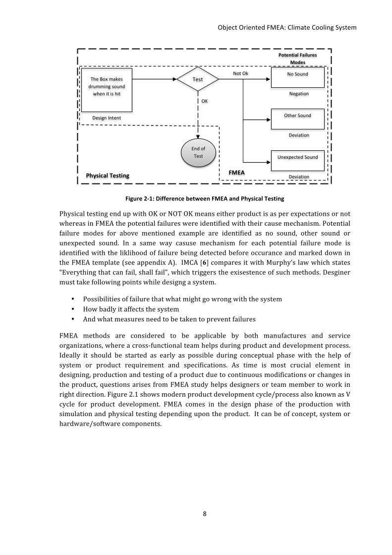
2.1 FMEA by Defination According to AIAG, FMEA is considered as an analytical methodology, which ensures the consideration and results of the potential problems during the product or process development. It is stated as an effective tool, where risks can easily be analysed, prioritise, mitigate or eliminate by the users. In general FMEA helps in anticipating the possible failure from a product or system before its implementation. In addition to just anticipating possible failure, FMEA also records the cause and effect of that failure in a spreads-‐sheet with the likelihood of failures being detected before occurrence. It is known to be theoretical testing method. Figure 2.1 shows the difference between physical testing and simple FMEA where a box is making a drumming sound when the user hits it.
Object Oriented FMEA: Climate Cooling System
8
Figure 2-‐1: Difference between FMEA and Physical Testing
Physical testing end up with OK or NOT OK means either product is as per expectations or not whereas in FMEA the potential failures were identified with their cause mechanism. Potential failure modes for above mentioned example are identified as no sound, other sound or unexpected sound. In a same way casuse mechanism for each potential failure mode is identified with the liklihood of failure being detected before occurance and marked down in the FMEA template (see appendix A). IMCA [6] compares it with Murphy’s law which states “Everything that can fail, shall fail”, which triggers the exisestence of such methods. Desginer must take following points while designg a system.
• Possibilities of failure that what might go wrong with the system • How badly it affects the system • And what measures need to be taken to prevent failures
FMEA methods are considered to be applicable by both manufactures and service organizations, where a cross-‐functional team helps during product and development process. Ideally it should be started as early as possible during conceptual phase with the help of system or product requirement and specifications. As time is most crucial element in designing, production and testing of a product due to continuous modifications or changes in the product, questions arises from FMEA study helps designers or team member to work in right direction. Figure 2.1 shows modern product development cycle/process also known as V cycle for product development. FMEA comes in the design phase of the production with simulation and physical testing depending upon the product. It can be of concept, system or hardware/software components.
No Sound
Other Sound
Unexpected Sound
Deviation
Deviation
Negation
Design Intent
The Box makes drumming sound when it is hit
Test
OK
Not Ok
Potential Failures Modes
End of Test
FMEA Physical Testing

Object Oriented FMEA: Climate Cooling System
9
Figure 2-‐2: V Diagram of process development
It also facilitates the identification of potential problems in a design or process by analyzing the effect of lower level of failures. Recommendations are then made to reduce the likelihood of the problem facing and mitigate the risk, if it still occurs. FMEAs are categorized in design, process and conceptual or functional FMEAs, during design FMEA the analysis will look at a combination of functions and hardware. Sometimes it will include just hardware, and sometimes the analyst will take a detailed look at the system down to a piece-‐part level, especially when critical functions or hardware are involved [7].
Figure 2-‐3: Scope of FMEA
Figure 2.2 shows the recommended areas to focus in FMEA. Design engineers generally start working between the defined phases, in which they adapt the scope for analysis to reality like, if FMEA is started between the concept and system phase, focus will be given to design
Concept
Function and Architecture
Sub-‐System
Vehicle Testing & Validation
Implementation
HW and SW Components
Unit Testing & Verification
Integration Verification & Validation
Sub-‐System Verification & Validation
Too Slow
DESIGN VERIFICATION
Project Time line
Level of A
bstractio
n
Simulation
FMEA
Physical
Component Design
Concept Design
System Design
Legal requirement
High Level attributes
Technology Use cases Functions
Scope of a concept FMEA (Add quality history, system overlaps and cost)
Functional Design
Software design
Electrical + I/O design
Assembly design
Mechanical Design
Robustness Design
Scope of a Component Design FMEA
Software functions
Hardware functions
System attributes
ECU I/O interfaces
Communication
Scope of a system FMEA Input/Outputs Signal Logics

Object Oriented FMEA: Climate Cooling System
10
including functions, use cases and the legal requirements from the concept phase. Use cases, including the behaviour of all users can never be neglected [8]. It is very dificult to implement a highly manual FMEA (i.e. a report that is keyed in manually on to paper or into a spread sheet). A manual method is hardly found to be user friendly and hard to understand with also very limited access. Many companies use FMEA merely to satisfy the contractual requirements of their customers [9], some how users may find FMEA a tedious and time-‐consuming activity. It is often carried out early in the design cycle of a product. As after a prototype has been built, changes made in later stages will be very costly. Hence, there is considerable research that attempts to improve FMEA usage in the earlier stages of the design process, such as the conceptual design stage, which can be confirmed with the information available online but most of which are untested concepts.
Generally FMEA requires the identification of the followings from the system and is properly documented.
• Item(s)/Component(s) • Function(s) • Failure(s) • Effect(s) of Failure • Cause(s) of Failure • Current Control(s) • Recommended Action(s) • Plus other relevant details
All this information is carried out with the help of expert engineers from the system. In other words this method of theoretical testing focuses on generated potential failures and then provide their solution as recommended actions.
A typical FMEA incorporates some methods, to evaluate the risks associated with the potential problems identified through the analysis. The two most common methods, Risk Priority Numbers (RPN) and Criticality Analysis (CA). RPN is a decision factor based on the product of three ratings: occurrence, severity and detection. These ratings are scaled with numbers between 1 and 10 (see Appendix A). Failure modes with high RPN values are selected. The corresponding current controls (i.e. the solutions) will be implemented on the basis of the selected failures [10].
2.2 Literature Review (Traditional FMEA)
2.2.1 The Flame System: Price, Pugh, Wilson and Snooke [11] discussed an automated FMEA for electrical design circuits for which they took automobile wash-‐wipe system as an example. They described automated FMEA in three different steps, model building, FMEA generation and Interactive FMEA examination.
Model building is considered as the key element for automated FMEA, it includes two basic levels: functional level; that includes the purpose and behaviour of the system, structural level; which consists of electrical circuit and their descriptions. According to the authors/researchers Flame system describes a system in four categories system

Object Oriented FMEA: Climate Cooling System
11
decomposition, electrical circuit definitions, input devices and functional descriptions and is being implemented on wash-‐wipe system in section 3 of this research work. Now together all this information is used in step 2 for FMEA generation. It includes the effect generation and then assessment of occurrence, detection and severity numbers using FMEA standards. The effect generation part includes the identification of states/levels in which a system operates for example in wash-‐wipe case; turn intermittent wipe ON, turn slow wipe ON etc are the operational states, and then comes the comparison part where the result of each applied failure mode on a system is compared with the correct working of system. This gives the effect of failure mode on system, described in terms of
• State: that is different, • Function: which fails to operate and • Component within a circuit: which is in different state then expected.
These short descriptions will help then in assigning RPN numbers using FMEA Standards. Flame system experts suggests two ways of assigning RPNs in this paper either by taking help from the past retrieval cases means if an FMEA exists for a same system but of different model or year, possibility of same effect can be found therefore same values for severity, detection and occurrence can be used there. Or the RPNs are extracted from the component databases if a past case doesn’t exist. Then comes the analysing part, which gives engineers an opportunity to review results, order them according to RPNs, alter them and publish them as an FMEA report.
2.2.2 FMEA on Wind Turbines (WT) Hoseynabadi, Oraee and Tavner in [12] studied the existing design of 2 MW wind turbine incorporating with Doubly Fed Induction Generator (DFIG) and compare it with Brushless Doubly Fed Generator (BDFG) (commonly knows as R80 in RELIAWIND) of same rating using FMEA. This analysis was done for reliability purpose, using Relax reliability studio 2007 V2 as a software tool. In this research paper they categorized WT system in four different levels for starting FMEA, by keeping in mind that it wouldn’t be complex. Following figure shows its division.
Figure 2-‐4: FMEA implementation on WT system [12]
They considered 11 assemblies, consist of 40 sub-‐assemblies and 107 parts through whose failure modes are generated and then categorized them in three different states e.g. Mechanical, electrical and Material. Further on they relate a failure mode with their root causes categorized in structural, wear and electrical issues and calculate RPNs accordingly. Now in section eight of [12], they compare FMEA RPN results of 11 assemblies with their field failure rates extracted from available reliability data of recent years. They find some similarities and it was concluded that product of occurrence & detection and Failure rates
Level 1
Level 2
Level 3
Level 4
Wind Turbine
Assembly
Sub-‐assembly
Part

Object Oriented FMEA: Climate Cooling System
12
data gives such a close comparison that one can use FMEA for predicting failure rates for new turbines. However FMEA analysis on new wind turbines (BDFG R80*) was also done, to extract the RPN and failure rate and it was it was concluded that R80* WT are more reliable due to reliable generator and gearbox assemblies. They stated FMEA as a potential reliability tool for WT systems.
2.2.3 FMEA for Software Based Automation System: Haapanen and Helminen [13] apply FMEA on software based automation system they found FMEA on electrical & mechanical systems more state forward compared to software-‐based systems. As mechanical & electrical components are mostly supposed to fail, whose reasons or consequences are known easily or studied. While failure modes on software-‐based system are generally unknown as they displays result, which might be correct or incorrect you don’t know. They followed initial steps from IEC 60812 standard, which defines the followings while handling software-‐based systems.
• System boundary for analysis • Understanding function and system requirement • Criteria for failure/success • Elements by breaking down a system • Failure mode and cause effects of each element
They insist of identifying the correct level of analysis by decomposing the software-‐based systems and start the analysis from bottom level, as FMEA in general is a bottom-‐up method for conducting any system analysis. Figure shows their way of software-‐based system decomposition.
Figure 2-‐5: Decomposition of Software-‐based System by Haapanen & Helminen.
However after decomposing the system, they find it little hard to start with the functional level as in most cases they say it leads to rather extensive or complicated analyses and also due to the unknown failure modes of functional block this procedure seems unfeasible.
They concluded an FMEA is only applicable to some extent for software-‐based systems but a total verification and validation process of software-‐based safety critical application includes software FMEA of the system at proper level. It also gives the guidance for other validation and verification efforts by revealing the possible weak points which helps in creating the test cases for system testing. They also proposed combination of FMEA with fault tree analysis of
Software-‐Based System
System Software Application Software
System Services Software-‐Based System
Application Function
System Kernel

Object Oriented FMEA: Climate Cooling System
13
Maskunitty & Pulkkinen [14] similar to Bi-‐directional analysis (BDA) method. Using this fault tree method before applying, FMEA helps in determining most significant failure modes for system reliability.
2.2.4 FMEA based on Unified Modelling Language (UML) Hou and Wang [15] in 2011 presented their assessment by using unified modelling language (UML) for software interface FMEA. They stated it an effective approach for quality engineers to understand software design complexity like in flight control system of aircraft. They highlighted following six basic steps to construct UML based FMEA.
• Choice of software interface needs to analyse. • Determining analysis grade and assumptive conditions. • Possible failure modes. • Analysis of failure reason and effects. • Severity of failure. • Filling of FMEA table.
Whereas Herbert, Xuegao and Myron [16] highlighted some important features of UML for conducting software FMEA on the UML based system. They took an example of use case diagram for active/standby role in a plant communication system, which operates when components automatically switched from active to standby status. After specifying the control system, program, external events, specific methods for which failure modes are identified and their flow in use case diagram, they extract the potential failures and their causes from the system. All this information is carried out in FMEA worksheet of MIL-‐STD-‐1629 standard, from where designers or decision makers concentrate on failure modes with highest importance. Severity, detection method and remarks column helps in this regard and considered to be the output from the FMEA. They consider following four important features of UML for this process
• Requirement formats in every phases • Verity of automatically generated development products, • Allowed actions based on class specifications and the • Ability to highlight product assessment for FMEA.
The procedure applied in [11] [12] for hardware and [13] for software have one thing in common, all of them talked about breaking down the complete system in different levels to start FMEA from bottom to up. Where as Haapanen and Helminen [13] didn’t find FMEA alone enough for software based automation, they emphasis to use some other technique with FMEA for critical analysis of a system as they used fault tree analysis (FTA) technique with FMEA. Where as Price, Pugh, Wilson and Snooke [11] talked about generation of failure modes with building system models and then emphasis more on assigning the risk priority numbers (RPN) and similarly in [15] [16] authors talked about the system developed in UML with tools like Rational Rose and Rhapsody. They have their own working environment such as “use case diagram”, which is applicable to those who had knowledge. It’s quite ok for small systems or components but for complex systems it seems to be a tedious task to identified the flow of a system with just use case diagrams. On the other hand every one talked about system analysis but didn’t mentioned about defining the system boundary. We are presenting to solve these issues with Object Oriented approach in FMEA analysis.

Object Oriented FMEA: Climate Cooling System
14
Chapter 3
3 System Overview
3.1 Introduction A vibrant trend towards making smaller and fuel-‐efficient vehicles is functioned now days, where special efforts are also made to reduce carbon di oxide emission. This leads to upgrade the internal combustion engines for low consumption vehicles, which brings a new era in car industry by introducing electrical and Hybrid vehicles. Although the first hybrid car was supposed to be built in 1899 by Ferdinand Porsche known as System Lohner-‐Porsche Mixte and later on Henry Ford also establish first automobile assembly line in 1904. But at that time due to less power and high prices, compared to gasoline vehicles they unable to attract customers. Then in 1960, United States took initiative and encouraged use of electric vehicles to curb air pollution and over the next 25 years, spent billions of dollars in research and development. While modern automotive hybrid technology was then well spread in late 1990s, when first mass-‐produced hybrid vehicle Toyota-‐Prius was launched in Japan (1997). Later on in 1999 Honda Insight also releases its first hybrid electric vehicles in United States but with release of Toyota-‐Prius in United States (2000), this hybrid technology was given recognition and acceptance from the users [17].
Right from the early days, when combustion engines were introduced methods for controlling the heat transfer through different metals was taken into consideration; special measures were also taken to avoid excessive metal temperature. Liquid cooling was one of them used in automotive applications, however different solutions were presented over the years for cooling. In early days water was used as the standard cooling fluid in automobiles due to its low cost, ease availability and good thermo-‐physical properties but later on due to relatively high freezing and boiling point, which results in engine/radiator block, a percentage of ethylene glycol was mixed with water, which bring the freezing point form 0 degree to -‐37 degree [18]. This cooling fluid was then pumped in the engine and later on passed through the heat exchanger, which transfers the engine heat to atmosphere. In modern vehicles the concept remain almost same for managing engine heat, while little improvements have been made in design and efficiency of the system/components (like radiators, pumps, Fans etc).
In hybrid vehicles, waste heat generated from electric powertrain system is very small and are better controlled through thermal management system. Coolant flow and energy from exhaust gas are used as an additional source of power for hybrid vehicles. It then leads improved designs for air conditioning systems, which also guarantees good level of cabin comfort without affecting the vehicle driving capability/range [18].

Object Oriented FMEA: Climate Cooling System
15
Figure 3-‐1: Air conditioning comfort in the vehicle [18]
Climate comfort level due to air conditioning system are of great concerned and more challenging in modern vehicle designs like variable air flows, thermal satisfaction, multiple climate zones, pleasant odours etc as shown in figure 3.1.
If you have experience, A/C comfort directly affects the potential range in electrical vehicles; energy must be saved for auxiliary equipment during air conditioning through new designs, efficient systems and special additional function like pre and post air conditioning etc. Similarly cooling and heating (at low temperature) systems are required for maintaining the performance and life span of lithium-‐ion batteries in hybrid vehicles.
3.2 Climate Comfort in Conventional Vehicles: Strict requirement are placed on air-‐conditioning acoustics in conventional vehicles with combustion engines and to some extent they were masked by the noise of internal combustion engine. Recently in past few years several improvements have been made, like use of silent HVAC (Heating, Ventilation, Air-‐Conditioning) modules and low noise blowers etc. But the basic principle was to reduce increased fuel consumption caused by air conditioning system. ECO-‐A/C and ECO-‐Heat systems were then introduced for this purpose with conventional refrigerant based air conditioning system. ECO-‐A/C makes it an efficient system with introduction of highly efficient internal heat exchangers within refrigerant circuit with an addition of energy saving adjustment by refrigerant expansion valve at evaporator unit. Similarly in ECO-‐Heat, highly efficient internal heat exchangers within refrigerant circuit were used and partial recirculated air mode was introduced for eliminating risk of window misting. Heat from exhaust gas was recovered for cabin heating or engine warm up, which reduces the functionality of air conditioning system and fuel consumption in hybrid vehicles [19].
Draft-‐free Ventilation
Zone Based air conditioning
Acoustics
Stratification
Cool Head
Warm feet

Object Oriented FMEA: Climate Cooling System
16
3.3 Climate Comfort in Hybrid Vehicles Hybrid vehicles were further consists of two main types: Full and Micro Mild Hybrid Vehicles.
3.3.1 Micro & Mild Hybrid Vehicles: Micro hybrids are built with conventional combustion engines having extra feature of start/stop automation, where as Mild hybrids were equipped with a small electric engine with powerful battery unit. Electric engine drive in mild hybrid is used for fast acceleration when required and recovering their brake energy helps in charging the battery.
Heating and Cooling: Air conditioning system is power by the belt-‐driven compressor just like conventional combustion engines vehicles, which stops the compressor when engine is idle. A cold storage device called storage evaporator is used for providing cooling in summer when the engine is briefly stops at traffic lights etc. where as engine waste heat with residual heat during brief stop and/or electric heater is used for maintaining climate comfort in cold climate.
A/C system acoustics: Noise of A/C is easily heard when engine is idle therefore improvements are required in system acoustic here. It is considered to be the weak system so far for micro & mild hybrid vehicles.
Fuel Saving via Start/Stop: In urban traffic environment with the used of storage evaporator functionality fuel consumption is cut down up to 8 approximately. As without storage evaporator for cooling battery, engine must be re-‐engaged way before the end of the period of inactivity, therefore start/stop fuel saving potential cut by half roughly [19].
3.3.2 Full Hybrid Vehicles: These vehicles are not only capable of boosting but in-‐fact they can cover some serious distance using electricity as a sole energy source. Hybrid vehicles are equipped with complete electric powertrain with a powerful battery system. Currently lithium-‐ion batteries are used for this purpose, which are completely/partially recharged while the vehicle is in motion by converting brake energy into electric power.
Cooling: Electric compressors are used here to cool down the passenger cabin, either driving with combustion engine or electric drive mode. Even though if engine is idle or during the necessary vehicle stop. Additional features like pre cooling (cooling passenger cabin through remote like before entering etc) is also possible in full hybrids, which certainly enhances the comfort level, as temperature normally rises above 50 C to 60 C during heating, which discomfort passengers in the cabin. But cooling through engine-‐independent system is dependent upon the available battery capacity.
Heating: Internal combustion engine are one of the source for heating in full hybrids on the other hand high voltage PTC (Positive Temperature Coefficient) heaters are also used, when internal combustion engine fails to deliver the required amount of heat.
Acoustics: Due to the long inactivity of the internal combustion engine, air conditioning system acoustics are important part to address therefore improved silent HVAC and silent blower are used in full hybrid vehicles.

Object Oriented FMEA: Climate Cooling System
17
Battery Cooling: Temperature regulation for lithium-‐ion batteries must be done in hybrid vehicles as they operated in a narrow temperature range. Battery is cooled by the refrigerant cooling circuit, where battery itself and on-‐board comfort compete for energy. Therefore a choice/priority must be set between cooling passenger cabin and electric drive unit.
Battery charging is done using external electric outlets in plug-‐in hybrids, which helps in full electric drive. Additional functionalities of pre-‐heating or pre-‐cooling cabins are also available in these vehicles, which over come the use of energy-‐intensive heating or cooling [19].
3.4 Electrical Components for Climate comfort
3.4.1 Storage Evaporator It’s basically consists of two cores: one known as main evaporator core and the other storage evaporator core. Cooling refrigerant is passed in parallel through both these cores during air conditioning. A latent medium inside storage core is cooled to freeze and helps it in becoming cold storage. This latent medium now starts melting once the A/C system in inactive for instance like during vehicle stop at traffics signals etc. Vehicle cabin airflow through battery cooling unit draws an amount of thermal energy, which helps the storage core to do.
3.4.2 High Voltage PTC These heaters were installed as insufficient waste heat is produced for heating purpose during electric drive in full or plug-‐in hybrids. PTC technology [20] helps in ensuring on-‐board comfort level; they are high voltage auxiliary heater integrated in HVAC module, which also saves the crucial packaging space for hybrid vehicles. PTC semiconductor is used as the heating element in these heaters, which gives significant increase to their electrical resistance, having temperatures above threshold and maintain a constant heating temperatures to its element during change in supply voltages or loads.
3.4.3 Silent HVAC Module: Using new soundproof/transparent material like resonance/interference sound absorbers airflow noises are optimises through air ducts.
3.4.4 Silent Blower: Blower motor with improved decupling arrangements acoustically enhanced; therefore low noise blowers are made to over come the noise of blowers.
3.5 Electrical Architecture Hybrid Vehicles at Volvo Electrical architecture of the V60 plug-‐in Hybrid vehicle is divided in high voltage and 12 volts system. 12V section is more likely the same as of conventional cars with an internal combustion engines but without an alternator used in hybrid vehicles. These 12V are supplied from the high voltage section in hybrid vehicles.
High voltage section is mainly used for driving electric A/C compressor having voltage capacity of 230V to 400V. It consists of both alternating (AC) and direct currents (DC), as the battery stores DC but generators/motors are operated with 3-‐phase AC. The charge current form the main power circuit is AC. High voltage components are also connected to the 12 V circuit for control signal. Figure 3.2 shows the high voltage components for Hybrid vehicles.

Object Oriented FMEA: Climate Cooling System
18
Figure 3-‐2: High Voltage electrical components in Hybrid Vehicles [21]
1 shows the Integrated Starter Generator (ISG), which is used for starting the internal combustion engine and current generation for the high-‐voltage section. Sub-‐figure 2, in figure 3.2 shows the Control Module for DC/DC converter that converts the high-‐voltage DC to 12V DC. Sub-‐figure 3 shows the charging cables with ground fault circuit interrupter and control unit for setting the charge current. 4 show the high voltage battery for driving ERAD (electric rear axle drive) and other high voltage components. Sub-‐figure 5 states the Inverter System Controller (ISC), which contains two separate voltage converters; IGM (Inverter Generator Module) for direct current to high voltage battery and IEM (Inverter ERAD Module) which uses 3-‐phase alternating current for different components. IGM and IEM also include the software to control the ISG and ERAD respectively. On board charger (OBC) control module (battery charger) is shown in sub-‐figure 6 of figure 3.2. It converts the main AC power of 230V to 400V DC for charging high-‐voltage battery, and operating electrical A/C and DCDC during main power recharging. 7 show the ERAD motor, which is usually mounted directly on the rear axle. It also works as a generator with energy recovery during braking. Charging socket is used for connection to main power 230V shown in sub-‐figure 8 whereas sub-‐figures 9 show the electric A/C compressor used for cooling in the compartment and HV battery.
3.6 System Overview Thermal Management system for hybrid vehicles at Volvo Car Corporation (VCC) is divided into two departments; one deal in thermal management powertrain (Engine side) and the other take care of the thermal management climate (Passenger compartment/cabin). Powertrain side deals with the airflow and coolant flow system of cars while climate side deals with cooling, heating and battery cooling system for hybrid vehicles. Figure 3.3 shows the hierarchy system of thermal management system at VCC.

Object Oriented FMEA: Climate Cooling System
19
Figure 3-‐3: Hierarchy of Thermal Management System at VCC
3.6.1 Thermal Management Powertrain
3.6.1.1 Airflow This system is responsible for providing the desired flow of air to different parts/system, when the request has been made. Airflow is required usually during the high load or for Air conditioning system (condenser). Engine cooling fan helps in this regard as the key source element. But it has a significant current consumption and noise level therefore it is only active when absolutely required by the system. Upper and lower shutters further help in this regard that is they must be closed to reduce the aerodynamic drag. Typically the shutters will be closed during winter, but during warmer months they may not close until high speeds are attained. In hybrid vehicle case a fan can be used to avoid the electric drivetrain temperature exceeding the threshold that is the peak temperature for electric drivetrain, it is triggered by the high voltage battery system. Following are the listed electrical components used in obtaining the desired airflow.
• Active Grill Shutter Module (AGSM) • Active Spoiler Shutter Module (ASSM) • Engine Control Module (ECM) • Cooling fan for standard cooling pack (e.g. Engine coolant radiator and air-‐
conditioning condenser (FCM)) • Cooling fan for hybrid cooling pack (Electric drivetrain coolant radiator and HV
battery coolant radiator (EDF)).
3.6.1.2 Coolant Flow Coolant flow section in divided in three different loop for hybrid vehicles as cooling for high voltage battery and ERAD system are additional coolant loops as compared to the conventional vehicles.
Engine loop: Petrol engines usually have a quick warm up phase by having a low or no coolant flow at the start of driving cycle. Once engine has attained adequate temperature, the pump shall be controlled nominally to provide coolant flow through engine block while its surrounding components depend upon the set points. If high load is detected, then to provide
Thermal Management
Powertrain
Airflow
Coolant flow
Climate
Heahng system
Cooling system
Baiery cooling system

Object Oriented FMEA: Climate Cooling System
20
maximum power from engine, the coolant set-‐point temperature is lowered. Electrical warming of thermostat and secondary control of the coolant flow via the pump attain this.
In combustion engines, cooling circuit includes CISG component that operates a starter moment and generates 400V for high voltage system. CISG has a coolant flow request to electrical pump, which obtains an adequate flow rate. Figure 3.4 shows the coolant flow for combustion engines.
Figure 3-‐4: Diagram of Coolant flow in Engine
ERAD loop : For the electric drivetrain (low temperature) circuit, the flow rate is based on a minimum requirement from electric propulsion that depends on ambient temperature. The electric drivetrain components can also increase coolant flow rate via dedicated CAN signals. Figure 3.5 shows the coolant flow of ERAD system.
Figure 3-‐5: Diagram of ERAD Coolant flow
This cooling circuit works in three phases. Cooling: Thermostat is used to reduce the pressure drop and allows a minimum flow under all driving conditions and all external temperatures. When thermostat is open the coolant travels to electric water pump through ERAD radiator and recirculates to cool down CIDD, OBC and ERAD circuits. Bypass: It works when coolant is at low temperature and the cooling is not required. In this mode, thermostat does not open to the radiator so the coolant travels directly to the water pump, which recirculates the coolant in the ERAD cooling system. Connecting to the engine’s cooling system: Pure electric power operates, when the coolant temperature (engine oil) of the combustion engine is 0 degC in hybrid vehicles. At low

Object Oriented FMEA: Climate Cooling System
21
temperatures there is a risk of combustion engine to not start quickly enough when extra power is required like in quick accelerations. If the combustion engine is cold and the low temperature cooling circuit is warm, a 3-‐way valve opens so that the coolant travels to the engine block to heat up combustion engine more quickly. This connection is also used for filling and bleeding the low temperature circuits. Filling is carried out with the help of expansion tank used for engine coolant flow system where as bleeding through this expansion tanks requires two 3 way valves. Battery loop: Similarly the battery coolant circuit is basically a low coolant circuit operating at a maximum temperature of 35degC. It maintains the temperature of the battery cells during driving between 25degC and 32degC, which is optimal for battery’s service-‐life and capacity. This loop has its own radiator used to cool down the coolant with the help of an electric water pump. Chillier with A/C system further enhance cooling for this battery cooling loop. Figure 3.6 shows the coolant flow in battery cooling circuit.
Figure 3-‐6: Diagram of Battery Coolant flow
Following are the listed electrical components used in coolant flow system for hybrid vehicles. • Engine Control Module (ECM) • Engine Coolant Pump Module (ECPM) • Electric Drivetrain Coolant Pump (EDCP) • Vehicle Dynamics Domain Master (VDDM) • Coolant level Sensor • Coolant Temperature Sensor for Electric Drivetrain • Electrical Thermostat actuator • Engine Coolant Temperature Sensor
3.6.2 Thermal management climate Thermal management climate system divided in three basic subsystems responsible for making comfort level for users in passenger compartment/Cabin. Airflow and coolant flow also plays an important role here with them to obtain desired comfort levels.
3.6.2.1 Cooling System Cooling system is responsible for cooling passenger cabin and high voltage battery in hybrid vehicles. It holds the basic Air conditioning system in the car where key elements are compressor, condenser and Evaporator. Compressor is the main source in this system for providing cooling. Principle of Air Conditioning: A low-‐pressure vapor entering the compressor is compressed and becomes a high pressure/temperature vapor, which is then injected to condenser. This condenser condenses the vapor into high pressure/temperature liquid as heat is released due to cooler ambient air passing through it. High pressure/temperature

Object Oriented FMEA: Climate Cooling System
22
liquid is then travels through the Thermal expansion valve (TXV) where small variable orifice provide some restriction, against which compressor pushes and suction side of compressor pull the high pressure/temperature liquid. In result it gives a low-‐pressure liquid, which then passes through the evaporators coil. Heat has removed from warm air, blowing across the evaporator fins into cooler refrigerant, from where this cooled is ducted into cabin with the help of blowers. The A/C cycle begins again as this low-‐pressure refrigerant is compressed and discharge under pressure [22]. Figure 3.7 shows the general principle of A/C system in vehicles.
Figure 3-‐7: Air Conditioning system [22]
In hybrid vehicles Internal heat exchanger (IHX) is used as an enhancer to increase the cooling capacity as shown in figure 3.8. It uses the cold vapor from the evaporator to cool the hot liquid before it enters the expansion device, resulting an increase in cooling. Evaporators are the part of Heating, Ventilation and Air Conditioning (HVAC) system. Small vehicles with 2 rows have only front evaporator whereas vehicles with 3 rows are separated in front and rear evaporators. Similarly an additional loop is defined in the hybrid vehicles to cool down the high voltage battery with the help of chiller attached after the condenser in A/C circuit. This chiller is designed for efficiently transferring the waste heat from secondary circuit to evaporated refrigerant as shown below in figure 3.8.

Object Oriented FMEA: Climate Cooling System
23
Figure 3-‐8: Cooling system for battery and Passenger compartment in Hybrid Vehicles
Working of Cooing system for hybrid vehicles: In hybrid vehicles one might know cooling is needed for passenger compartment, electric drive components and High voltage battery system. Cooling of electric drive components have its own cooling system with a separate cooling radiator as discussed before in section 3.6.1.2 where as A/C system helps in enhancing the cooling for battery loop. Figure 3.9 shows the working of cooling system.
Figure 3-‐9: Working of cooling system for hybrid vehicles
Cooling Passenger Compartment and High Voltage Battery: When cooling the passenger compartment only, the solenoid valve (7) for the climate control module evaporator (9) is open and the solenoid valve (13) for Battery Climate Unit (BCU 12) is closed. This is the A/C system's normal operating condition where none of the solenoid valves are powered. When cooling the passenger compartment and high voltage battery, the solenoid valve (7) of the climate control module evaporator (9) and solenoid valve (13) for BCU (12) is open. Solenoid valve for BCU is powered and the A/C compressor (2) in this case works in the entire speed range of 800-‐8500 rpm [21].
Battery R
ad
1
0
EXP TANK Electric valve Temp sensor Electric water pump
Battery!
Condenser
C
Chiller
Rea
r eva
pora
tor
Fron
t eva
pora
tor
IHX
Chiller Shutoff Valve
Orifice
Orifice TXV
AC / Front HVAC Shutoff Valve
Rear HVAC Shutoff Valve
Temp Sensor

Object Oriented FMEA: Climate Cooling System
24
Cooling high Voltage Battery: When cooling the high voltage battery only, the solenoid valve (7) for the climate control module evaporator (9) is closed. Solenoid valve (13) for BCU (12) is open. During this operating condition both solenoid valves are powered. The A/C compressor (2) works in the speed range 2000-‐4000 rpm [21].
Compressor is considered to be the key source for the providing cooling to the system. In hybrid vehicles, electric compressor is used instead of mechanical (as in conventional vehicles), which is powered by direct current (DC) from high voltage battery. They had a built-‐in voltage converter that converts direct current to 3-‐phase alternating current for compressor’s electric motor. This electric motor is a 3-‐phase 400V synchronous motor with an output of 4.6 kW and it operates at a rotational speed from 800 to 8500 rpm. Air condition control module (ACCM) controls the motor and communicates with the Engine control module (ECM) with a communication bus. BCU and CCM are the control units for the battery management system and climate management system (cooling, heating and component heating/cooling).
3.6.2.2 Heating System Heating system includes the heating of passenger compartment/Cabin with additional services of pre-‐heating during winters. As the waste heat in electric and hybrid vehicles are not or temporarily produced through their engines, electric heating system with the help of air and water heating system were introduced. It is done with addition of fuel operated heater (FOH) and auxiliary electric heaters commonly known as high voltage PTC heaters. PTC Air heaters (Low Voltage heaters), mostly used in pure electric vehicles and are commonly controlled by HVAC control panels. They boost up the required amount of temperature inside the cabin as they directly heat the ambient air. Hybrid vehicles on the other hand are equipped with high voltage PTC water heaters, placed inside the coolant circuit, which makes use of engine waste heat for heating. PTC heater then becomes the additional heat source for heating, which also helps in improving energy efficiency [23].
Mean while this thermal management climate section provides some additional luxuries to passengers as stated below
Pre-‐conditioning/Parking Climate: This function is used while engine is OFF in both cold and warm climate to pre climatise the passenger cabin usually when the vehicle is parked. High Voltage Coolant Heater (HVAC) is used as a heat source while Electrical Compressor (ELAC) is used as a cooling source. Vehicles can be either plugged (connected to main as power supply) or unplugged where as high voltage battery is used as the power supply. Pre-‐conditioning is activated by direct start or timer functions. Direct start climatise passenger compartment for a maximum duration with the available actuators, depends upon the car configuration. Timer start function climatise the compartment up to a specific time configured by the user. Following systems/actuators are possibly control during preconditioning.
• High Voltage Coolant Heater (HVAC) • Positive Temperature Coefficient (PTC) • Seat Heating • Steering wheel Heating • Electrical Windscreen Defroster • Electrical Rear Window Defroster

Object Oriented FMEA: Climate Cooling System
25
• Mirrors Heaters • Electrical AC
Seat heating: This function is mostly installed in luxury vehicles, which helps in comfort level for passenger. They are individually controlled with four different levels (off, 1, 2, 3) through IHU.
Defrosting: This function is required to de-‐ice or demist the windscreen as fast as possible. Electrical heated windscreen and hot air flow through defroster outlet helps in fulfilling this function. It holds both automatic and manually handling facilities through IHU.
Head level estimation for providing Heating/Cooling etc: In VCC comfort level is said to be OK, when the (Drivers) head level temperature is similar to the set temperature, therefore a mapping technique is used which gives the estimated head level temperature depending upon the air-‐flow, ambient temperature and INCAR sensor reading. Climate control system is responsible for providing this information correctly as all calculations have been done there. While cooling and heating managers are responsible for providing heating and cooling comfort level in the passenger cabin with the help of this head level estimation.
Thermal Expansion Valve (TXV): Its basic principle is to ensure the complete evaporation of liquid refrigerant from the evaporator, so that maximum cooling is achieved. Figure 3.10 shows both open and close version of TXV. TXV allows more refrigerant to enter evaporator inlet, when it is said to be open. Refrigerant in the capillary tube expands with the increase in temperature at evaporator outlet, it then forces the diaphragm downwards which pushes the spring and hence the ball valve is open. Similarly the cooler evaporator outlet tube helps in contracting capillary tube, pressure compensation tube and spring force. It will then help diaphragm and pin to move upward which allows the ball valve to close the path for refrigerant.
Figure 3-‐10: Thermal Expansion Valve [22]
1. From Filler Drier 2. To Evap. Inlet 3. Capillary tube 4. Metering Orifice 5. Ball valve 6. Spring 7. Diaphragm 8. Refrigerant 9. Pressure tube

Object Oriented FMEA: Climate Cooling System
26
Orifice: Its basic principle is to drop the pressure and temperature of the refrigerant, when refrigerant flows through it. It is done with the helps of fine restriction placed inside the orifice tube as shown in figure 3.11. The rate of flow depends on the pressure difference across the restriction.
Figure 3-‐11: Orifice tube [22]

Object Oriented FMEA: Climate Cooling System
27
Chapter 4
4 Methodology Object oriented approach is basically an iterative loop that begins and concludes with the requirement description and specifications as shown below in figure 4.1. The first two steps of OO-‐FMEA distinguish it from the traditional approach. Every step comes up with defined inputs and outputs; while the combined output from the first two steps is an object oriented system analysis consisting of a boundary diagram with a group of objects illustrates the overall behaviour of the system.
Figure 4-‐1: Iterative loop of Object Oriented Failure Mode and Effect Analysis
In general terms the process of designing any concept, system or component in a defined operational environment, no matter either its hardware, software or combined together, results in creation of a structure. Then the structure is allocated certain behaviours or functions. This is a simple view of the outcome of a design engineering process. OO-‐FMEA theoretically tests the design by first finding its structure and then identifying its behaviours or function. Structure and behaviour are two keywords obtained before starting traditional FMEA methodology in Object-‐Oriented approach. Figure 4.2 shows the flow chart of the object oriented failure mode and effect analysis (OO-‐FMEA).

Object Oriented FMEA: Climate Cooling System
28
Figure 4-‐2: Flow Chart of Object Oriented Failure Mode and Effect Analysis
4.1 Identifying Structure Step one asked for finding conceptual or system structure means a complete system boundary diagram that consists of the interacting models; software/hardware components, input/output components and external shared resources which helps in performing a certain function. The purpose of identifying complete structure is to have complete operational environment, which includes communication networks and the external shared resources. Mechanical elements can also be taken into consideration for designing an appropriate boundary. But one should be quite clear among the difference between interfaces and interaction in order to determine the system boundary figure 4.3 shows the difference among them, which is set to be the criteria for identifying the system elements in object oriented approach for FMEA. Any element, which is unique, or having an interaction with system considered to the part of system boundary, whereas elements with only interfaces is not necessary for system boundary.
1. Find the Conceptual or system structure
2. Identify the objects and their behaviors.
3. Prioritize objects, enter names & design intents in
FMEA template.
4. Generate Failure modes, based on design intents
5. Complete FMEA according to FMEA methodology
SCOPE Boundary Diagram
FMEA OBJECT Physical, Logical & attribute objects with design intents
INITIAL FMEA INPUTS Partial risks
POTENTIAL FAILURE MODES
FMEA RESULTS More reliable designs, improved specifications & knowledge gains
Concep
t or system
specificatio
n & expertise

Object Oriented FMEA: Climate Cooling System
29
Figure 4-‐3: Difference Between Interaction and Interfacing in OO-‐FMEA
4.2 Identify the Behaviour. From the confines of the system boundary, a process of identifying objects and their design intents will start. The output from this step highlights complete system behaviour comprises of physical, logical and attribute objects. An object is an information package containing a name and a brief but accurate description of design intent for a separable part of the system. Physical objects represent separable hardware or tangible components in a system like electronic control units, relays, switches, sensors, actuators etc. whereas logical objects represent separable, coherent functions or behaviours; they are often realized by software. While attribute objects are tricky ones, they represent the intangible characteristics and can be implemented by other objects (physical & Logical) like Noise Vibration Harness, serviceability, driveability, tolerance etc. It is considered to be the most important and crucial one for improving reliability and enhancing perceive quality in a system, one need to be smart enough and creative for identifying attribute objects. There is no intention to imitate nomenclature from other methodologies, but the same object structure in the design can be adopted [8]. Figure 4.4 shows an example of these objects having design intents.
Figure 4-‐4: Physical (Blue), Logical (Red) and Attribute (Green) Objects in OO-‐FMEA
The design intent of an object is defined from the perception of what it does in the system. The motivations for its actions can also be included to enhance effect identification. The information shall answer the question of what the object does, where applicable and why. Correctly formulated design intents enhance the identification of the failure modes in a system; therefore it’s important to be precise and accurate, always start with the verb and define targets of action, in the end answer when and why [8]. Good design intent must fulfil all these properties.
Interface: One-‐way effect/communication
Interface: Two-‐way effect/communication, but no feedback
Interaction: Interdependent effect, should belong to the same system
Windshield Wiper Motor
Supplies rotational mechanical force to a linkage system for moving two windshield wipers back and forth across the shield
Rain-‐Sensor Control
Activates windshield wiper at set wiping speeds and intervals base on sensor input information
NVH Compatibility (Noise-‐Vibration-‐Hardness)
Limits perceived wiper noise to prevent annoyance to passenger.
Physical Object Logical Object Attribute Object

Object Oriented FMEA: Climate Cooling System
30
This step further helps in identifying the relationship between different system elements and also captures the dependencies between system and external shared resources, which gives a complete picture as a whole.
4.3 Priorities the object and enter the information. Complex systems usually contain both complicated and simple elements, where complicated elements perform varying and simple elements perform highly repetitive tasks. Therefore a key is to choose only right but fewest objects to analysis, which are crucial for the system. It exploits the principle of efficient compatibility rather than unmotivated completeness. In other words, the analysis targets on the significant issues. Due to interactions between the objects usually the high priority objects will include the effects of the low priority objects. As focus is set to perform qualitative analysis instead of a quantitative analysis, which enables focus on significant objects only, especially those having key impact on system behaviour. After prioritization, simply transfer the information in the objects to the FMEA-‐template (see appendix A). Reused objects that are derived from stable standard components, regulated by proven design guidelines, can be exempt from transfer to the FMEA, if their designs intents and operation environments are not changed.
4.4 Generate failure modes. A failure mode in general is the way things fail, but this may create confusions when working with designs at different level of development phase. In OO-‐FMEA, failure modes are defined as the negation or deviations of design intents. The outputs of each object are expected to conform to the design intent. Any deviation is a failure mode. Two types of non-‐conformance are possible negation or deviation from the design intent. In other words, failure modes are things not working at all (negation) or not working as intended or expected (deviations). Thus, formulating the negation and deviations of the design intent generates potential failure modes. Note that this is a golden rule to be followed in object oriented FMEA. It is principally important to strictly abide by this rule when performing analysis for software. Figure 4.5 shows an example of generating failure modes.

Object Oriented FMEA: Climate Cooling System
31
Figure 4-‐5: Generation of Failure Modes in terms of Negation & Deviation
FMEA process is evaluated and documented in a form of template as shown in figure 4.6. It is divided in two parts Theoretical testing and Risk Analysis. Prioritization and generation of failure modes from the design intents comes under theoretical testing in-‐fact they are consider as the inputs to the FMEA template.
Figure 4-‐6: OO-‐FMEA Template
Objects (A) holds the prioritised objects while Item/Function (B) are the Design intents of the prioritised objects in FMEA template and then comes the Potential Failure Modes (C) derived from the design intents as discussed in section 4.4.
No Sound
Other Sound
Unexpected Sound
Deviation
Deviation
Negation
Design Intent
The Box makes drumming
sound when it is hit
Test
OK
Not Ok
Potential Failures Modes
FMEA

Object Oriented FMEA: Climate Cooling System
32
4.5 Completion of FMEA After generating all the failure modes from the design intents of prioritized objects, process of logical reasoning will start. Logical reasoning is provided for identified/generated failure modes, which contains the potential effect of those identified failures, cause mechanisms, preventive measures and then the verification methods for physical testing. Figure 4.7 illustrates the flow chart of it.
Figure 4-‐7: FMEA methodology used in OO-‐FMEA template
A potential failure effect holds the consequences of identified failure mode for the end user, as well as all the design aspects to create a robust system. Details of these potential effects are considered as a decisive factor for the choice of design solutions, therefore it is recommended to be concise but precise that is as specific as possible. Every failure then must have the cause mechanism, which is categorised in emergent occurrences, noise factors and communication medium. In complex systems emergence is the most common phenomenon. Lets take an example of a malfunctioned actuator controlled by a sensor to understand the difference between the categories. Figure 4.8 shows this phenomenon, here red text shows the emergent occurrences, green text is the noise factor where as blue text shows the communication medium error.
Failure Effects
Cause or failure
mechanism (O)
Prevention Prevention (requirement or spec.)
Detection (D)
Recommended Action
Responsible Action taken
YES
NO
Verifies
S2
O2
D2
RPN

Object Oriented FMEA: Climate Cooling System
33
Figure 4-‐8: Identifying potential failure modes using OO-‐FMEA
Preventive measure section includes all the documented requirements used for eliminating the causes or identified potential failure modes. First time, it usually consists of recommendations set by the team/group of engineers performing FMEA and also considered as one of the vital steps for addressing identified failure modes. Then comes the validation methods, some time people get confused about the difference between Design Prevention and design detection, validation methods are considered as the part of design detections, where as specification or requirements are part of design preventions. Figure 4.9 below illustrates the relationship between them.
Figure 4-‐9: Meaning of design Prevention and design detection in OO-‐FMEA
In the end risk assessment is done with the help of risk priority number (RPN), which is the part of risk evaluation. RPN is basically a product of Severity, Occurrence and Detection ranking numbers, based on standardized evaluation criteria. The acceptance level of RPN depends on the ambition of the design team, but generally an item scoring more than 100
Sensor Control Actuator Activate Request Apply
21
Timing
Unexpected user behaviour
Conflict with other sub-‐system or function
21
External shared resource errors
Incorrect inputs parameters
21
Error states from other subsystems of function
21
Noise from operational environment
Abuse
2
1
Communication error
Cable Harness
Design Prevention
Requirements
OR
Specifications
Design Detection
Validation method
OR
Verification method

Object Oriented FMEA: Climate Cooling System
34
requires recommended actions. After the implementation of an action, a lower RPN will be the outcome. It is a challenge to judge the level of Occurrence for the failure modes. Knowledge on quality history, Software and hardware reliability data, component specification, system design, and the type of technology applied, contributes in accuracy of choosing a reasonable value. Although there are general ranking tables commonly used but systems designers are urged to create ranking that are appropriate for their system. Rankings are categorised between numbers from 1 to 10.
Severity ranking encompasses what is important to the industry, company or customers like safety standards, environment, legal, production continuity, scrap, loss of business, damaged reputation etc. A low number reflects a low impact of severity while high impact is highlighted with high numbers.
Occurrence ranks the probability of a failure occurring during the expected lifetime of the product or service. A high number reflects the inevitable occurrence and vice versa.
Detection ranks the probability of the problem being detected and acted upon before it has happened. Low numbers reflects the detection is very likely to be happen while high number shows not likely to be.
The ranking tables of Severity, Occurrence and Detection based on Automotive Industry Action Group (AIAG) are given in appendix A.
After the first run through, FMEA achieves Loop 1 status. The team continues to schedule work session to solve problems and follow-‐up the recommended actions and document the subsequent measures taken. Critical or significant items are tagged with classifications YC and YS. Those that cannot be handled in the product development phase must be transferred to a Control Plan that addresses the issues correctly in production. YC denotes a potential Critical characteristics, derived from the severity ranking 9-‐10 where as YS denotes a potential Significant characteristics, derived from a combination of severity ranking in the interval 5-‐8 and occurrence ranking 4-‐10. FMEA achieves the final status, when all recommended actions are appropriately taken and documented [8].

Object Oriented FMEA: Climate Cooling System
35
Chapter 5
5 Implementation This chapter includes the implementation of OO FMEA on climate cooling system for hybrid vehicles at Volvo Cars. It comprises of five steps mentioned in chapter 4. Climate cooling system consists of passenger compartment cooling, high voltage battery cooling and ERAD cooling system. Electrical Compressor and HVAC system installed in mostly hybrid vehicles plays an important role for this.
5.1 Structure Figure 5.1 shows the structure of the cooling system, where the dotted green line shows the system boundary. The elements, which are inside the system boundary, include all those control modules and actuators that interact with each other in order to maintain or provide cooling to the system.
Figure 5-‐1: System Boundary of the cooling system
Electronic Control Module (ECM) is considered to be the back bone for cooling system, as one can see from the figure 5.1, all the sensors and actuators like shutoff valves (for chiller and AC ON/OFF), coolant water pumps (for ERAD and AC loop), Coolant Thermostat, ACCM (which holds the AC compressor) and Fan Control Module (FCM) are controlled by ECM with the help of different control units present inside ECM. Then comes the Battery Energy Control Module (BECM), which is connected with Battery Coolant Pump and Shutoff valve for maintaining the temperature of battery. Central Electronic Module (CEM) and TEM are used for inputs/requests with the help of sensors/users here while climate control module (CCM) is

Object Oriented FMEA: Climate Cooling System
36
used to cool down rear end (third seat row; if available) with the help of rear Heat-‐Ventilation AC (HVAC) system. Control modules either communicate through CAN (spotted by bold red lines) or Flex-‐Ray buses (Bold blue lines), while communication among actuators are control units are through LIN buses (brown dotted lines) or hardwire (usually only having ON/OFF function). Similarly actuators or control units having only the interfaces didn’t come inside the system boundary as per the rule stated in section 4.1 like power relays etc.
Number of electronic components like actuators, sensors, there control units, entertainment and navigation systems are developed in recent years to make passengers feel safer and make travel more comfortable. Several new bus systems are developed or improved to meet these design challenges, depending upon the operational requirements. These Bus systems create a Topology, Reza Esmaeeli states it as an architecture focuses on the relationship between its elements and internal structures, rather than the characteristics of it’s elements; when internal relationships between the elements of architecture are capable of change [24]. Bus system is the most important system currently used in cars; LIN, CAN, MOST and FlexRay, where LIN, CAN and FlexRay are commonly used for control systems and MOST for telemetric applications.
Figure 5-‐2: Network topology mostly used by automation industry
5.1.1 CAN (Controlled Area Network) CAN is the most important and commonly used bus system in automotive industry as a message-‐based protocol. But still it is not considered for very fast or low data rates/transmissions (where only few parts are used for data transmission), new buses are designed for that purpose [25]. CAN was started in 1983 at Robert Bosh GmbH and is one of five protocols used in on-‐board diagnostics (OBD) vehicles diagnostics standard, mandatory for all vehicles sold in European Union Since 2004 [26]. Control units are able to share and exchange data through it, its message signal consists of a sequence of binary digits or bits and

Object Oriented FMEA: Climate Cooling System
37
operates at data rate of up to 1Mbit/s. A CAN message may vary between 44 and 108 bits in length [27]. It is shown with bold red colour in figure 5.2.
5.1.2 LIN (local Interconnected Network) LIN (shown in figure 5.2 with brown dotted lines) is usually developed/used for less complex networks, where use of CAN make it too expensive. It is a serial bus designed for networking intelligent devices like sensors and actuators within a subsystem like sunroof or heating control etc, which do not require high transmission/data rates or complex fault management. LIN specification was first defined by joint venture among BMW, DaimlerChrysler, Audi, Volvo, Motorola, Volcano and VW, Later on in 2001 Atmel also joined this group in developing LIN 2.0 specifications. LIN supports the data rate of up to 19.6 kBit/s for which a 12V single wire is sufficient enough [25].
5.1.3 FLEXRAY FlexRay is considered as the fast and fault-‐tolerant bus system in automation industry. It was designed for car control application, requires high bandwidths. Therefore it supports data transmission with a bandwidth of up to 10Mbit/s, which is quite acceptable for real time operations [27]. BMW and DaimlerChrysler introduced FlexRay in 1999, while Atmel also joined them on the latest development of FlexRay 2.0 in June 2004. It was especially developed for X by wire systems, such as steer-‐by-‐wire systems or brake-‐by-‐wire where robust error management and data transmission is required and is based on “byteflight”; a communication system earlier developed by BMW [25]. Flexray is shown with bold blue colour in figure 5.2.
5.1.4 MOST (Media Oriented Systems Transport) MOST is used for all kinds of multimedia applications; navigation, telecommunication, audio and video systems, due to its high data rate in synchronous (up to 24.8Mbit/s) and Asynchronous (up to 14.4Mbits/s) transmission modes. Additional control channel with data rate of 700kBits/s is also available there for boosting the transmission. It was first developed by BMW and DaimlerChrysler in 1998 and later on in August 2004 releases the latest specification MOST 2.3. Furthermore Plastic Optic Fiber (POF) is used as physical layer to ensure safe data transfer, which is not vulnerable to EMC [25].
As stated earlier hybrid vehicles consists of high voltage and conventional 12 volts circuits. These 12V section contains the LIN (Local Interconnect Network), CAN (Controller Area Network) and MOST (Media Oriented System Transport) for communication within electrical control units (ECU) and actuators.
5.2 Behaviour Second step of OO-‐FMEA extracts system behaviour categorized in objects; logical, physical and attribute objects as stated in section 4.2. Combining all these information gives a complete behaviour of a system. We have extracted this information from system requirement descriptions of climate cooling system. Following three sections illustrates the investigated behaviour of climate cooling system.
5.2.1 Logical Objects Logical objects usually contain information (in form of design intents) regarding electrical control units used in the system. Table 5.1 shows the logical objects extracted from climate

Object Oriented FMEA: Climate Cooling System
38
cooling system. Some of them are later on prioritized and then evaluated using FMEA methodology.
Table 5-‐1: Logical Objects and their deployment in identified using OO-‐FMEA in cooling system
Logical Objects Deployment Cooling Manager ECM Compressor Control ECM Compressor ACCM Air Flow for Cooling ECM Valve Manager ECM HV Battery Cooling Valve Control ECM A/C Shutoff Valve Control ECM HV Energy Storage BECM Climate Control Function CCM Vehicle Mode Management (VMM) CEM Compressor Power Limitation Function ACCM
Cooling Manager: This control unit plays an important role in providing cooling to passenger compartment. It is located inside the Engine control module (ECM) and interacts with different logical units upon a request made for cooling from the user. It is responsible for maintaining the desired cooling to passenger cabin.
Compressor Control: It is also located inside the Engine control module, which helps in maintaining climate comfort while communicating with electrical compressor and cooling manager. It estimates the required compressor speed with the help of designed algorithms where in this case it’s a feed forward PID control loop. PID part tries to reduce the error between the evaporator temperature and set point temperature while feed forward part has number of maps that calculates compressor speed based on the inputs from sensors like recirculation degree, in-‐car temperature, evaporator set-‐point temperature, mass air flow in front HVAC and ambient temperature.
Compressor: It is the control part of the actuator, which drives the electrical compressor with the help of compressor control unit defined above. It also holds the status of the compressor, which includes the current speed, ON/OFF, pressure at the discharge side of the compressor, voltage and power consumption etc. It is basically located inside the Air Conditioning control module (ACCM) shown in figure 5.1.
Airflow for Cooling: It estimates and provides the required airflow to condense the air conditioning refrigerant.
Valve Manager: It controls the refrigerant flow in A/C loop towards the chillier, front and rear shutoff valves (ON/OFF) and holds their status in order to communicate with different subsystems.
HV Battery Cooling Valve Control: It controls the refrigerant flow either to pass or bypass the battery radiator. Its deployment is also in ECM.

Object Oriented FMEA: Climate Cooling System
39
5.2.2 Physical Object As from its name it is quite obvious that it includes all those physically present objects/actuators which helps in providing or maintaining the cooling comfort level for passenger cabin like shutoff valves, water pumps, Fan Control Module, LIN etc. Table 5.2 shows all those physical objects highlighted in this regard. Figure 5.1 also shows all these actuators in the system boundary, as they interact with control units for providing cooling comfort.
Table 5-‐2: Physical object and their functions identified using OO-‐FMEA in cooling system
Physical Objects Function LIN Communication Bus Flex ray Communication Bus Cable Harness Assembly of power cables Fan Control Module Helps in providing cooling Coolant Thermostat Passes or by pass the engine coolant from Radiator A/C Shutoff valve Open/Close front HVAC for cooling Rear Shutoff valve Open/Close rear HVAC for cooling Chiller Shutoff valve Open/Close chiller valve for enhancing battery cooling HV Battery Shutoff valve Passes or by passes coolant from battery radiator Coolant water Pump Pumps coolant in engine cooling circuit LT Coolant water Pump Pumps coolant in ERAD cooling circuit (low temperature circuit) Battery Coolant water Pump
Pumps coolant in Battery Cooling circuit
5.2.3 Attribute Object As we have discussed earlier in chapter 4 that attribute objects includes those conditions or events, which should be taken under consideration while developing/writing the different products/functions. Similarly Table 5.3 shows the highlighted attribute objects from climate cooling system, which is taken under consideration while designing this system.
Table 5-‐3: Table of Attribute objects and their functions identified in cooling system
Attribute Objects Function Noise Vibration Harness Handling Coolant Temperature Limits Define the upper and lower limits for coolant temperatures Cooling Prioritization Prioritize battery, ERAD and Compartment cooling De-‐Gas/ Filling Balance How to set the coolant level if it goes beyond threshold Component Protection From high/low voltage, high/low pressure etc Assembly and Service Define the time duration Electrical Noise Handling Handle electrical radiations, define insulations type/kind
5.3 Prioritization Prioritization has been done from the logical objects, whose design intents are then taken under consideration for further investigation. As from the definition, the purpose behind prioritization is to analyse fewest objects, which targets significant issues or some how over come the design intents of other objects as well. So here focus is given to the control units, which directly affect the cooling comfort level. Following are the six prioritize objects, used in the next step of OO-‐FMEA.

Object Oriented FMEA: Climate Cooling System
40
• Cooling Manager • Compressor Control • Compressor • Airflow for Cooling • Valve Manager • HV Battery Cooling Valve Control
These prioritised objects, having system behaviour are taken as inputs to FMEA process.
5.4 Failure Modes Each design-‐intent of prioritised logical objects were then critically analysed with engineering team of climate system, and any possible negation or deviation was highlighted as a failure mode. Those failure modes are further analysed using traditional FMEA methodology discussed in section 5.5. Compressor control object is discussed as a case study in this report, which is known to be the source for maintaining cooling comfort level.
5.5 FMEA Methodology In FMEA methodology the template of FMEA is filled with the help of theoretical study and risk analysis as illustrated in chapter 4. Following are the design intents extracted from the compressor control function, which are discussed using FMEA methodology.
• Implements gain scheduling (feedback loop) with dependencies of ambient temperature and mass airflow through Front HVAC for improving the performance of compressor.
• Improves controller performance by a feed forward control as a complement to normal control algorithm. Contribution elements include Evaporator set points, ambient Temperature, estimated head level temperature and recirculation degree.
Above mentioned design intents suggest that a PID control with feed forward function is used to control the speed of the compressor which have dependencies on ambient temperature, evaporator set point (set temperature by the user), recirculation degree and an estimated head level temperature. Now besides an inefficient implementation of the controller one of the cause mechanism includes the wrong estimation of head level temperature. Head Level estimation involves different parameters like INCAR sensor and temperature measured across HVAC outlets etc. This estimation is considered to be the most complex estimation and is currently under investigation therefore currently they don’t have any design prevention for it but suggests to be detected while performing a complete simulation.
To understand further behaviour of the compressor control function in hybrid vehicles three different test scenarios were also created, where data from In-‐Car temperature sensor, Evaporator Temperature sensor, Ambient Temperature sensor, Coolant temperature sensor, total mass air flow, recirculation degree and vehicle speed was recorded. But the focus was to obtain the compressor speed with change in evaporator temperature.
Case 1: At 15:00Hrs, certain day of September in Gothenburg, compressor speed and evaporator temperature were measured when the car was parked. Air conditioning system was not disturbed initially, with a set temperature of 15degC (low) while the ambient

Object Oriented FMEA: Climate Cooling System
41
temperature was recorded 11degC. Figure 5.3 and 5.4 shows the compressor speed and evaporator temperature values respectively.
Evaporator temperature = INCAR Temperature – Heat load inside the cabin
Figure 5-‐3: Compressor Speed with fixed fan speed while vehicle is in Steady State
Figure 5-‐4: Evaporator temperature with fixed fan speed while vehicle is in Steady State
Note: Evaporator temperature regulates from 2degC to 20degC on varying temperature nob from 15degC to 25degC by the user .The sensor attached after the evaporator measures

Object Oriented FMEA: Climate Cooling System
42
evaporator temperature or it is roughly equivalent to measured INCAR temperature minus heat load inside the vehicle.
Case 2: Same day later on compressor speed and Evaporator temperature were measured while car was moving with a constant speed of 50 km/h approximately outside the hilly areas in Gothenburg, Sweden. Air conditioning system was not disturbed while temperature was adjusted to minimum at 15degC and ambient temperature was recorded as 16degC. Figure 5.5 and 5.6 shows the measured evaporator temperature and compressor speed respectively.

Object Oriented FMEA: Climate Cooling System
43
Figure 5-‐5: Measured evaporator temperature with fixed fan speed while vehicle is moving.
Figure 5-‐6: Compressor Speed while fixed fan speed while vehicle is moving.
Case 3: Later on in the evening compressor speed and evaporator temperature was measured with auto fan and climate settings. Vehicle was moving with constant speed of 50km/h with an ambient temperature of 16degC. Compressor speed and evaporator temperature were shown in figure 5.7 and 5.8. Set temperature was change with time to time as shown in figure 5.7.

Object Oriented FMEA: Climate Cooling System
44
Figure 5-‐7: Evaporator temperatures measured at auto fan & climate setting
Figure 5-‐8: Compressor speed measured with auto fan & climate setting
These user cases give better understanding over dependencies among different estimations and sensors. On behalf of which all information was first carried out in FMEA template and Risk Priority Number (RPN) was generated across them by doing risk analysis with the help of severity, occurrence and detection level as shown in figure 5.9. Similarly it has been done for each and every design-‐intent of prioritised objects mentioned in section 5.3.

Object Oriented FMEA: Climate Cooling System
45
Figure 5-‐9: FMEA methodology on compressor control logical objects
After doing assessment on all prioritised objects, OO-‐FMEA template gives the following histogram shown in figure 5.10. It shows the distribution of risk among prioritised objects with the number of design intents in each object. Here y-‐axis shows the number of design intents in each prioritised object while X-‐axis shows those prioritised objects. Whereas dark colours show risk seriousness among the objects, which must be addressed properly or those design intent needs to be review.
Figure 5-‐10: Distribution of risk priority numbers for cooling system
0
2
4
6
8
10
12
Compressor Control:
Compressor (Cmprlf)
Cooling Manager
Valve Manager
Air Flow for Cooling
Cou
nts
151-200 101-150 51-100 1-50

Object Oriented FMEA: Climate Cooling System
46
Chapter 6
6 Results and Recommendations After reviewing all design intents from prioritise objects using FMEA methodology following assessment has been made to robust current thermal management climate cooling system:
Ø In compressor control function compressor starts switching speed from 0 to 800 rpm once the evaporator temperature is reached to the comfort level, this behaviour leads to loss the function that is compressor can be damage due to this on/off function. Figure 6.1 shows the set point set by the user as one can see in between 850 sec to 1100 sec when evaporator temperature reached the level of set-‐point and similarly in time period of 1300 to 1500Sec, during these time periods compressor is continuously switching between zero and 800 rpm, this can damage the compressor or effects the life time of compressor.
Figure 6-‐1: Evaporator temperature and Set point temperature
Ø We have seen that more emphasize is given to cool down HV battery in extreme conditions apart from which a suggestion has also been made for heating HV battery during too long parking in cold weather conditions like at airports etc.
Ø After reviewing the designs, we came to know that Flap actuators design (more then 12 in total), which helps in maintaining climate comfort level are very weak as all the these flaps were connected in series. Means failure of any flap will lead to a complete loss of function. These flaps actuators have open and close function dependent upon the request made by the user.

Object Oriented FMEA: Climate Cooling System
47
Ø Similarly as you can see from the figure 6.2, rear HVAC valve is connected to CCM but is controlled function according to the specifications lies in Engine control module through valve manager. This makes it a little complex as the decision is taken inside ECM and then directed to CCM, which further take action. A suggestion has been made to connect it with ECM to have a robust design.
Figure 6-‐2: System Architecture cooling system
Ø Similarly threshold for opening the chiller shutoff valve, coolants flow and water coolant temperature was not mentioned, which help in battery cooling.
Ø It was not cleared from the requirements/specifications that is their any temperature control system exist for second/third seat row in SPA Hybrid vehicles as at some places it was found that a user sitting behind in third row can set the temperature by his/her choice. If that is the case then head level estimation for all users must be required, while at some places it is mentioned that temperature is adjusted through first row and rest are adjust accordingly means have dependencies on first row.
Ø There are rooms of improvements in the system requirement descriptions (SRD) for example some words are not standardized like a word mass airflow is used as total mass airflow, airflow, total airflow. Do you think is their any difference between them?
6.1 Comparison between traditional FMEA & OO-‐FMEA Ø While comparing Object Oriented approach with traditional FMEA approach, one can
easily identify the inputs and outputs of the system. Figure 6.3 shows those identified objects, highlighted in step 2 of OO-‐FMEA for cooling system. Sensors and actuators represent inputs and outputs respectively to the cooling control system (controllers). While traditional FMEA approach didn’t have system elements at one place.

Object Oriented FMEA: Climate Cooling System
48
Figure 6-‐3: Overview of Inputs, Output and Control system from cooling system
Ø Similarly as these identified objects holds complete behaviour of that particular function, it’s easy to reuse them in other design if required. There is no need to dig into entire system requirement again. It fulfils the reusability issue and in same manner easily upgraded with new functions like in software upgrades. Whereas it is uncertain in traditional FMEA approach.
Ø Object Oriented approach of FMEA also helps us in solving unnecessary complex solutions like after doing this thesis work we came up with the new decomposition of the thermal management climate system as shown in figure. Where cooling system is responsible for cooling at compartment, battery and ERAD, Heating System is responsible for providing heating to compartment and climate control system responds to component heating/cooling like seat heating, pre conditioning, defrosting, demisting etc. Figure 6.4 shows the before and after dependencies of the thermal management climate system.
Figure 6-‐4: Decomposition of Thermal Management Climate System before and after OO-‐FMEA Implementation
Ø Object Oriented approach consider to be most suitable for lean and agile processes whereas traditional approach is not adapted for modern processes
Ø It also reduces the product development time and contributes to better prototypes and testing methods as compared to traditional FMEA approach.
Cooling Manager
Climate Control
Airflow
Valve Manager
HV Energy Storage
A/C shutoff Valve
Cooling Thermostat
B-‐ coolant water Pump
HV Battery Shutoff Valve
Fan Control Module
ACCM
Ambient Temperature
Sensor
A/C coolant water Pump
Actuators/Output Controllers/system Sensors/Input
Coolant Temperature
Sensor
A/C Pressure Sensor
Heating System
Climate System
Cooling System
Battery & ERAD Cooling System Th
ermal
Man
agem
ent
Clim
ate
Heating System
Battery cooling system
Cooling System
Thermal
Man
agem
ent
Clim
ate
Before After

Object Oriented FMEA: Climate Cooling System
49
A small survey was also conducted in Volvo Car Corporation (VCC), to get opinions from different people who did analysis using both the techniques that are Object Oriented-‐ Failure Mode and Effect Analysis (OO-‐FMEA) and traditional Approach of FMEA. It gives a brief idea that how well OO-‐FMEA works in
• Handling complex systems • Ease to use and update • Time Efficient • Identifying
o Ambiguous requirements o Incomplete designs o Unmotivated solutions o Interactions and Interfaces
Figure 6-‐5: Pie chart showing engineers response on OO-‐FMEA under a survey
67% people believe that OO-‐FMEA is quite capable of identifying Interaction and interfaces between different systems and subsystems, whereas 72% says OO-‐FMEA is good enough for identifying incomplete designs, while 7% rated OO-‐FMEA very good and 14% fair enough in identifying incomplete designs. 74% in total suggests that OO-‐FMEA is fair or good enough in identifying unmotivated solution on the other hand 93% supports in favour of OO-‐FMEA for identification of ambiguous requirement in system designs.
0% 7% 14%
72%
7%
Idenbfy Incomplete Design
13% 0%
20%
67%
0%
Idenbfy Interabons & Interfaces
7% 0%
40% 53%
0%
Idenbfy Ambigious Requirements
13% 13%
27%
47%
0%
Idenbfy Unmobvated Solubon

Object Oriented FMEA: Climate Cooling System
50
Figure 6-‐6: Pie charts showing OO-‐FMEA Usability, Time Efficiency and Handling complex system
The key advantage of OO-‐FMEA over traditional method is its ease and reusability, time efficiency and the object oriented way of handling complex designs. When it was asked in VCC, 80% marked it fair and good for easy use and upgrade, while 13% says its too good and endorsed OO-‐FMEA over traditional approach. In case of time efficient 80% rated OO-‐FMEA good and fair enough (the average time an FMEA of a system took 1 year approximately). 27% believe OO-‐FMEA is very good in handling complex system designs while 80% favour it good and fair enough as compared to traditional approach of FMEA. Figure 6.5 and 6.6 shows the pie charts of these analyses conducted through a survey inside Volvo Cars Corporation.
7% 0%
40% 40%
13%
Ease to Use and Update
0% 13%
13%
47%
27%
Handle Complex Systems
7% 13%
33%
47%
0%
Time Efficient

Object Oriented FMEA: Climate Cooling System
51
Chapter 7
7 Conclusion and Future Work If a method or tool is not easy to use or understand, it always discourages the user and if it does not conform the real world, it will consider being short-‐lived. This report shows an Object Oriented approach for Failure Mode and Effect Analysis (FMEA) to handle complex system in terms of time, ease to reuse and capability to identify incomplete and ambiguous requirements etc.
FMEA is qualitative analysis, which is achieved here by quality inputs provided by OO-‐FMEA approach. It is concluded that OO-‐FMEA requires the practitioner to have basic knowledge of complex systems. Performing OO-‐FMEA for complex systems is more feasible, relevant and effective because of their dependences on other components, highlighted by interaction and interfaces, whereas it’s hard to find dependencies in traditional FMEA approach while dealing in complex systems. Some authors mentioned it to over come it in addition with some other reliability tools but then traditional approach become more time consuming. OO-‐FMEA is applied to climate cooling system in this thesis work, which solves the problem of unnecessary complexity to the system by splitting battery and ERAD cooling system from main cooling system. Another benefit of OO-‐FMEA approach is of getting separable behaviours of different units, which can easily be utilized in other analysis or while system enhancement. System boundary gives a clear overview of the system achieved in OO-‐FMEA whereas traditional FMEA didn’t hold system boundary. Over all from this analysis we concluded that OO-‐FMEA cover all the vital aspects of a system designing first by providing a structure that is transparent and accessible and then focusing on critical issues while prioritization step which confines the principles of modern, lean product development process.
7.1 Future Work Usually an FMEA took 1.5 to 2 years to complete therefore due to time constraints this analysis is done considering only proposed logical objects of cooling system, physical and attributes objects are not considered in FMEA methodology so far. This process will acquire loop one status once FMEA methodology is also implement on highlighted physical and attribute objects of thermal management cooling system. After which process of recommended action taken place and modified set of specifications and requirements are published. This needs to be done as a part of future work. On the other hand Thermal Management System also holds the heating part, a partial work on heating system was also done that is its structure and logical objects was highlighted and it is recommended to perform OO-‐FMEA on heating system to get the complete picture of Thermal Management Climate system.
Secondly we have seen in general three different kinds of systems:
• Data Processing Systems • Transaction Processing Systems • Control systems

Object Oriented FMEA: Climate Cooling System
52
This report illustrates OO-‐FMEA approach for controller-‐based systems where different components or processes are interconnected for a specific goal in edition with some defined inputs to get some defined outputs. Whereas it is also applicable for Data Processing Systems [28], where compilation, recovery, correction and storage of data is key and must be correct in certain time period as being a real time system. Data base management systems in libraries, banks, job portals etc. are the best example in this regard. Similarly it can also be applied to Transaction Processing System [29], where detailed information is captured and processed, necessary to update data after validating. If they are not correct system a simple error message is generated for the user. Like in bank accounts, shopping malls etc. All this information must be secure and reliable, as any failure will leads to big setback. Although both of these kinds are not complex as of control units but failure among them will leads some serious problem. OO-‐FMEA will give an opportunity to make them more reliable and efficient systems.

Object Oriented FMEA: Climate Cooling System
53
8 GlossaryAttribute object
It’s an information package, containing a name and design intents of an intangible characteristic related to system or component like electromagnetic compatibility, corrosion tolerance, maintainability, drivability etc. they are dependent upon logical and physical objects.
Behavior
It refers the functional and non-‐functional activities carried out by a certain system in an operational environment.
CAN
It’s a standard communication bus used in vehicles as a communication medium among microcontrollers and deferent devices without a host computer. CAN stands for controller area network having data rate of 1Mbit/s.
Design Intent
It refers to the motivation behind its creation. Design intent of an object holds the reason behind their creation having functions, behavior or states.
External Shared Resources
External shared resources usually don’t interact with system but have an interface which for significant for the system.
Emergence
It is the way complex system behaves as a result of interaction, dependencies and other exchanges or influences that may or may not be intended.
Flex Ray
It is a little expensive but faster and more reliable automotive communication protocol developed after CAN and LIN. It supports high data rate of up to 10Mbit/s
FMEA
FMEA is one of the most widely used procedures for analysis of potential failure modes. It’s applied to reduce or eliminate failures with higher priorities from a system. Actions are taken after applying FMEA to reduce risks of system failures. It stands for Failure Mode and Effect Analysis.
Interaction
In simple words it’s a two-‐way communication among two different systems or elements with feedback.
Interface
Interface is when data is transmitted from one entity to another without any feedback between the connected entities. The transfer of data can be one or two ways, but is independent of each other.
LIN
LIN stands for local interconnect network, used for communication among different components in vehicle. It is based on serial network protocol with data rate of 20kbit/s.
Logical objects
It is information package containing name and design intent of a separable part of the software, mostly a coherent functions in a control unit. Functions can be realized by combination of hardware and software like electric motor control, voltage-‐monitoring unit etc.

Object Oriented FMEA: Climate Cooling System
54
MOST
Media Oriented System Transport is used as a high-‐speed multimedia medium for inside /outside communication in modern vehicles. It’s a serial bus, which transport audio, video, voice and data signals using plastic optical fiber (POF).
Object
Here in this report or in OO-‐FMEA object is referred as an information package representing a separable part of a system. It consists of name and description of its design intents.
Physical Objects
Physical object is an information package containing the name and design intent of a separable hardware or tangible element in a system like relay, switches, sensors, pumps etc.
Risk Priority Number (RPN)
Risk priority number extracted from the product of severity, occurrence and detection level of failure modes, which highlights the seriousness of risk.
Special Characteristics
It tags critical or significant items. Those that cannot be handled in product development phase must be transferred to a control plan.
• YC is a potential critical characteristic, derived from severity ranking 9-‐10
• YS is a potential significant characteristic, derived from a combination of severity ranking 5-‐8 and occurrence ranking 4-‐10.
System
A number of interconnected elements, components or abstractions capable of receiving specified inputs and generating outputs makes a system or sub-‐system. Usually system consists of a number of sub-‐systems.
System Overlaps
It defines a common are of design responsibilities for two or more sub-‐systems.
System Structure
It is an overview diagram showing the construction of interdependent components and interfaces to other sub-‐systems in the operational environment, including external shared resources and an appropriate sub-‐system boundary.
Topology
Topology is the geometrical arrangement of modules and units in the networ

I
9 Bibliography [1] Volvo Cars Corporation. [Online].
http://www.volvocars.com/intl/top/corporate/pages/default.aspx
[2] Igor Ushakov, Probabilistic Reliability Models.: WILEY, 2012.
[3] Sultan Lipol and Jahirul Haq, "Risk Analylsis method: FMEA/FMECA in the Orginization," Basic & Applied Sciences, vol. 11, no. 05, 2011.
[4] Sellappan Narayanagounder and Karuppusami Gurusami, "A new approch for prioritization of failure mode in design using ANOVA," in World Academy of Science, Engineering and Technology, 2009.
[5] Yiannis Papadopoulos, David Parker, and Christian Grante, "Automating the Failure Modes and Effects Analysis of Safety Critical Systems," in High Assurance Systems Engineering, 2004.
[6] The International Marine Contractors Association (IMCA), "Guidance on Failure Modes & Effect Analaysis," Marine Division Management Committee, IMCA, 2002.
[8] Volvo Car Corporation, "Object-‐Oriented Design Failure Mode and Effect Analysis," Electrical & Electronics System Engineering , Göteborg, 2013.
[7] K Crow. (2002) Failure Mode and Effects Analysis (FMEA). [Online]. www.npd-‐solutions.com/fmea.html.
[9] Barrie Dale and Peter Shaw, "Failure mode and effects analysis in the U.K. motor industry: A state of the art study," Quality and Reliability Engineering International, vol. 6, pp. 179-‐188, 1996.
[10] P C Teoh and K Case, "Modelling and reasoning for failure modes and effects analysis generation," Engineering Manufacture, vol. 218, pp. 289-‐300, 2004.
[11] Christopher J Price, David R Pugh, Myra S Wislon, and Neal Snooke, "The Flame System: Automating Electrical Faliure Mode & Effects Analysis (FMEA)," in Annual Reliability and Mantainability, 1995.
[12] Hooman Arabian Hoseynabadi, Hashem Oraee, and Peter Tavner, "Failure Modes and Effect Analysis (FMEA) for Wind Turbines," Electrical Power and Energy Systems, vol. 7, no. 32, pp. 871-‐824, June 2010.
[13] Haapanen Pentti and Helminen Atte, "Filure Mode and Effects Analysis of Sofware-‐Based Automation System," VTT Industrial System, Säteilyturvakeskus Strålsäkerhetscentralen Radiation and Nuclear , Helsinki, 2002.
[14] M Maskunitty and U Pulkkinen, "Fault tree and failure mode and effects analysis of a digital

II
safety function," Industrial Automation, VTT Automation, Helsinki, Report 1994.
[15] Chenguang Hou and Qihua Wang, "Software Interface Failure Modes and Effect Analysis Based on UML," in International Conference of Information Technology, Computer Engineering and Management Sciences, Beijing, 2011.
[16] Herbert Hehct, Xuegao An, and Myron Hecht, "Computer Aided Software FMEA for Unified Modeilng Language Based Software," in Software Engineering, California, 2004.
[18] DELPHI, "Powertrain Thermal Managment," 2007.
[17] (2013, Nov.) Cars Direct. [Online]. http://www.carsdirect.com/green-‐cars/a-‐brief-‐history-‐of-‐hybrid-‐cars
[19] Peter Kroner, "Thermal Management for Hybrid Vehicles," Advance Engineering, Air Conditioning, Behr GmbH & Co. KG, Stuttgart, Germanay, Technical Press 2009.
[20] Edward Dulzer. PTC Electric Immersion Heaters.
[21] Volvo Car Corporation, "Hybrid Climate and Cooling System," Electrical and Electronics System Engineering, Volvo Cars Corporation, 2010.
[22] Ariazone Automotive & Industrial Refrigerant Services Equipment. Automative Air Conditioning Training Manual.
[23] Eberspächer, "PTC heating Systems for Vehicle Body Manfactures and Small OEMS," Climate Control, Eberspächer GmbH & Co. KG, Germany, 2013.
[24] Reza Esmaeeli. (2007) Topology-‐from Mathematics to Architecture.
[25] Atmel Markus Schmid, "Automotive Bus System," Atmel Applications, vol. VI, winter 2006.
[26] Sidorenko, Alex. ObdDiag.net. [Online]. http://www.obddiag.net/adapter.html
[28] Sushant. S. Sundikar, "Database System Concepts and Architecture," in Introduction to Database Management System.
[27] Tom Denton, "Multiplexing," in Automobiles Electrical and Electronic Systems. Oxon: Routledge, 2012, vol. IV, pp. 133-‐144.
[29] Christie Rowe. Study.com. [Online]. http://study.com/academy/lesson/transaction-‐processing-‐systems-‐tps-‐manual-‐and-‐automated-‐systems.html
[30] Mark A Morris, Failure Mode and Effect Analysis based on FMEA, November 30, 2011.

III
Appendix A
FMEA Template for AIAG: AIAG is the Automotive Industry Action Group, which currently compiles the FMEA standards for the North American Auto Industry
Figure 0-‐1: FMEA template according to AIAG [30]
Severity ranking encompasses what is important to the industry, company or customers like safety standards, environment, legal, production continuity, scrap, loss of business, damaged reputation etc. AIAG sets the following criteria for judging severity while doing risk analysis. (AIAG is the Automotive Industry Action Group, which currently compiles the FMEA standards for the North American Auto Industry)
Table 0-‐1: Severity ranking according to AIAG standards [30]
Effect Criteria: Severity of Effect on Product (Customer Effect) Rank
Failure to Meet Safety and/or Regulatory
Requirements
Potential failure mode affects safe vehicle operation and/or involves noncompliance with government regulation without warning. 10
Potential failure mode affects safe vehicle operation and/or involves noncompliance with government regulation with warning. 9
Loss or Degradation of Primary Function
Loss of primary function (vehicle inoperable, does not affect safe vehicle operation). 8
Degradation of primary function (vehicle operable, but at reduced level of performance). 7
Loss or Degradation of Secondary Function
Loss of secondary function (vehicle operable, but comfort / convenience functions inoperable). 6
Degradation of secondary function (vehicle operable, but comfort / convenience functions at reduced level of performance). 5
!
Item! Function!Potential!Failure!Mode!
Potential!Effects!of!failure!
S!Potential!Causes!of!Failure!
O!Current!Controls!for!Prevention/!Detection!
D!R!P!N!
Recommended!Action!
Responsibility!&!Target!Completion!
Date!
Action!Taken!
S!2!
O!2!
D!2!
R!P!N!2!
Action!Results!! ! ! ! ! ! ! ! ! ! ! ! ! ! ! ! !

IV
Annoyance
Appearance or Audible Noise, vehicle operable, item does not conform and noticed by most customers (>75%). 4
Appearance or Audible Noise, vehicle operable, item does not conform and noticed by many customers (50%). 3
Appearance or Audible Noise, vehicle operable, item does not conform and noticed by discriminating customers (<25%). 2
No effect No discernible effect 1
Occurrence ranks the probability of a failure occurring during the expected lifetime of the product or service. AIAG sets the following criteria for ranking occurrence in risk analysis methods.
Table 0-‐2: Occurrence ranking according to AIAG standards [30]
Likelihood of Failure
Criteria: Occurrence of cause
Design life/reliability of item/vehicle
Criteria: Occurrence of Cause –
DFMEA (Incidents per item/vehicle)
Rank
Very High New technology/new design with no history. ≥100 per thousand ≥ 1 in 10 10
High
Failure is inevitable with new design, new application, or change in duty cycle/operating conditions.
50 per thousand 1 in 20 9
Failure is likely with new design, new application, or change in duty cycle/operating conditions.
20 per thousand 1 in 50 8
Failure is uncertain with new design, new application, or change in duty cycle/operating conditions.
10 per thousand 1 in 100 7
Moderate
Frequent failures associated with similar designs or in design simulation and testing.
2 per thousand 1 in 500 6
Occasional failures associated with similar designs or in design simulation and testing.
.5 per thousand 1 in 2,000 5
Isolated failures associated with similar designs or in design simulation and testing.
.1 per thousand 1 in 10,000 4
Low
Only isolated failures associated with almost identical design or in design simulation and testing.
.01 per thousand 1 in 100,000 3
No observed failures associated with almost identical design or in design simulation and testing.
≤.001 per thousand 1 in 1,000,000 2
Very Low Failure is eliminated through preventive control. Failure is eliminated through preventive control. 1
Note: AIAG is the Automotive Industry Action Group, which currently compiles the FMEA standards for the North American Auto Industry

V
Detection ranks the probability of the problem being detected and acted upon before it has happened. Following table illustrates AIAG standard for ranking detection level, while performing risk analysis.
Table 0-‐3: Detection ranking according to AIAG standards [30]
Opportunity for Detection
Criteria: Likelihood of Detection by Design Control Rank Likelihood of
Detection
No detection opportunity
No current design control; Cannot detect or is not analyzed 10 Almost
Impossible
Not likely to detect at any stage
Design analysis/detection controls have a weak detection capability; Virtual Analysis (e.g., CAE, FEA, etc.) is not correlated to expect actual operation conditions.
9 Very Remote
Post Design Freeze and prior to launch
Product verification/validation after design freeze and prior to launch with pass/fail testing (Subsystem or system testing with acceptance criteria such as ride and handling, shipping evaluation, etc.).
8 Remote
Product verification/validation after designs freeze and prior to launch with test to failure testing (Subsystem or system testing until failure occurs, testing of system interactions, etc.).
7 Very Low
Product verification/validation after design freeze and prior to launch with degradation testing (Subsystem or system testing after durability test, e.g., function check).
6 Low
Prior to Design Freeze
Product validation (reliability testing, development validation tests) prior to design freeze using pass/fail testing (e.g., acceptance criteria for performance, function checks, etc.).
5 Moderate
Product validation (reliability testing, development validation tests) prior to design freeze using test to failure (e.g., until leaks, yields, cracks, etc.).
4 Moderately High
Product validation (reliability testing, development validation tests) prior to design freeze using degradation testing (e.g., data trends, before/after values, etc.).
3 High
Virtual Analysis – Correlated
Design analysis/detection controls have a strong detection capability. Virtual analysis (e.g., CAE, FEA, etc.) is highly correlated with actual or expected operating conditions prior to design freeze.
2 Very High
Detection not applicable; Failure
Prevention
Failure cause or failure mode cannot occur because it is fully prevented through design solutions (e.g., proven design standards, best practice or common material, etc.).
1 Almost Certain
Note: AIAG is the Automotive Industry Action Group, which currently compiles the FMEA standards for the North American Auto Industry