thermo solarcell
TRANSCRIPT

Applied Energy 120 (2014) 16–22
Contents lists available at ScienceDirect
Applied Energy
journal homepage: www.elsevier .com/ locate/apenergy
Performance optimization analyses and parametric design criteriaof a dye-sensitized solar cell thermoelectric hybrid device
0306-2619/$ - see front matter � 2014 Elsevier Ltd. All rights reserved.http://dx.doi.org/10.1016/j.apenergy.2014.01.048
⇑ Corresponding author.E-mail address: [email protected] (J. Chen).
Shanhe Su a, Tie Liu a, Yuan Wang a, Xiaohang Chen a, Jintong Wang b, Jincan Chen a,⇑a Fujian Key Laboratory of Semiconductor Materials and Applications and Department of Physics, Xiamen University, Xiamen 361005, People’s Republic of Chinab Department of Physics, Southern University, Baton Rouge, USA
h i g h l i g h t s
� An electric and thermal model of the solar hybrid device is studied.� Temperature effects on the performance of a dye-sensitized solar cell are discussed.� The performances of the solar cell and hybrid device are optimized and compared.� The criteria of optimal coupling and parametric design are obtained.� The hybrid device is proved to be an efficient system exploiting solar energy.
a r t i c l e i n f o
Article history:Received 3 August 2013Received in revised form 24 November 2013Accepted 16 January 2014Available online 7 February 2014
Keywords:Dye-sensitized solar cellThermoelectric generatorHybrid deviceTemperature-dependent coefficientPerformance analysisOptimum design strategy
a b s t r a c t
An electric and thermal model of the hybrid device consisting of a dye-sensitized solar cell (DSSC) and athermoelectric generator (TEG) is studied for exploiting the solar full spectrum. Analytical expressions forthe power outputs and efficiencies of the DSSC, TEG and hybrid device are derived. Temperature-depen-dent coefficients of the DSSC are introduced and their values being consistent with the experimental dataare determined. The effects of the operating electric current, working temperature and temperature-dependent coefficient in the DSSC on the performance of the hybrid device are discussed in detail. Theoptimum performance characteristics of the hybrid derive at different temperature conditions and theDSSC at the reference temperature condition are compared. The parametric design criteria of the optimalcoupling are given. These results obtained here may provide some guidance for the optimum design ofpractical hybrid devices.
� 2014 Elsevier Ltd. All rights reserved.
1. Introduction
The dye-sensitized solar cell (DSSC) has aroused considerableattention with the continuous growth of the advantages of its po-tential low cost, high solar energy conversion efficiency andincreasing stability, since reported by O’Regan and Gratzel [1]. Ithas shown a potential as a new renewable energy device. Inpractice, the DSSC is expected to be applied in widespread fieldsranging from Building-integrated photovoltaics to the mobile andhydrogen production due to its flexible, economical and high per-meable properties [2–6].
Although the DSSC may possess many attractive advantages incomparison with currently existing silicon semi-conductive solarcells, only solar spectrum wavelength larger than 800 nm can beabsorbed by the common used N3 and N719 sensitizers [7], and
at the same time, relaxation, interfacial transference, and recombi-nation process are the main factors governing the efficiency of en-ergy conversion [8,9], so that irreversible losses in the device limitthe performance of the cell. Various experimental and theoreticalstudies including the synthesis of new absorber materials[10,11], optimization of the metal oxides structure [12–14], appli-cation of tandem configuration [15,16], etc. have been carried outto improve the performance of the DSSC. However, few researchesare concentrating on recycling the vast waste sunlight whichmostly converts to heat. Until recently, several researchers [7]developed a novel hybrid system comprising a DSSC and a thermo-electric generator. Chang et al. used the integration of the CuO thinfilm to enhance the overall heat conduction [17]. Another systemcomposed of a DSSC, a solar selective absorber, and a thermoelec-tric device is proved to possess the probability of effectivelyincreasing the photoelectric conversion efficiency [18]. Mostresearches experimentally proved that the efficiency can beincreased by using a hybrid system. Since it is difficult to

Nomenclature
A effective area (cm)d thin film thickness (lm)D electron diffusion length (cm2 s�1)G solar spectrum intensity (mW/cm2)h overall heat leak coefficient (mW/cm2 K)i reduced current of the TEGI electric current of the TEG (mA)J current density of the DSSC (mA/cm2)k thermal conductivity (mW/cm K)K thermal conductance (mW/K)kB Boltzmann constant (J K�1)l electron diffusion length (cm)L length of thermoelectric arms (cm)m couple number of the TEGM ideality factorn(x) excessive electron concentration (cm�3)n0 electron concentration under a dark condition (cm�3)P power output (mW)q electron charge (C)Qh heat flow from DSSC to TEG (mW)Qc heat flow from TEG to the heat sink (mW)QL heat leak rate (mW)S Seebeck coefficient (V/K)T temperature (K)Ta temperature of the heat sink/environment (K)TH/L two temperatures of the hybrid device (K)V external voltage of the DSSC (V)x coordinate measured from the TiO2/TCO interface (lm)Z figure of merit (K�1)
Greek symbolsa light absorption coefficient (cm�1)b decreasing rate of the efficiency (K�1)b0 decreasing rate of the efficiency when the maximum
efficiency of the hybrid device is equal to that of theDSSC at the reference temperature condition (K�1)
q electrical resistivity (X cm)k decreasing rate of the power output (mW K�1)gopt optical efficiencyg efficiencyU incident irradiation intensity (cm�2 s�1)U0 light intensity at 1 sun condition (cm�2 s�1)s electron lifetime (ms)
Superscripts and subscriptsD dye-sensitized solar cellT thermoelectric generatoropt optimal valuen N-type semiconductor legp P-type semiconductor legsc short-circuit current densityref reference conditionoc open circuit
AbbreviationsDSSC dye-sensitized solar cellTEG thermoelectric generatorTCO transparent conducting oxide
DSSC
I3
S. Su et al. / Applied Energy 120 (2014) 16–22 17
experimentally quantify the interrelated parameters governing ahybrid system, theoretical modeling and numerical analysis be-come essential for the optimization of operating conditions andthe system design. Therefore, the motivation of the present paperis to clarify these issues and present a general and fundamentalanalysis of the performance characteristics of the DSSC, TEG, andhybrid system.
In the present paper, an electric and thermal model isestablished based on two existing models of a DSSC and a semicon-ductor thermoelectric generator. Temperature coefficient is intro-duced to determine the electrical performance of the DSSCdepending on temperature. Expressions for the power output andefficiency of the hybrid device are derived. To make the hybridsystem more competitive, a numerical optimization method isdeveloped for evaluating the performance of the each componentand total system. The effects of the operating electric current,working temperature, and temperature-dependent coefficients ofthe DSSC on the performance of the system are discussed in detail.The efficiency of the hybrid device is maximized at differentlygiven conditions. The optimal criteria of the parametric designare obtained.
TEG
Fig. 1. The schematic diagram of a DSSC–TEG hybrid device.
2. The description of a photovoltaic–thermoelectric hybriddevice
The photovoltaic–thermoelectric hybrid device shown in Fig. 1consists of a series-connected DSSC on the top and a series-con-nected semiconductor thermoelectric generator attached to theback side of the cell. When a ray of sun light incidents on the DSSC,it is partly lost by transmission and reflection. The rest light energy
is selectively absorbed by optical active substances such as the sen-sitized molecular in the DSSC and the solar absorber materialcoated on the bottom of the DSSC [7]. One part of the absorbed en-ergy is directly converted to electric and transported to the load.The remaining part of the absorbed energy converts into heat,which may be used to drive a TEG. By using such a hybrid device,the solar spectrum with all frequencies can be better utilized andconverted to electricity. Below, the thermal and electrical perfor-mance evolution of individual unit and overall system will begiven.

300 310 320 330 340 3500.00
0.05
0.10
0.15
0.20
0.25
0.30
Max
imum
Pow
er (m
W)
T (K)
experimental detaλ =0.00350 m WK-1
λ = 0.00506 m WK-1
λ =0.00730 m WK-1
Fig. 2. Curves of the maximum power of the DSSC varying with operatingtemperature.
18 S. Su et al. / Applied Energy 120 (2014) 16–22
2.1. The power output and efficiency of a DSSC
Structure and operation of a DSSC have been extensively stud-ied [1,9,19–27]. Under solar radiation, electrons of the dye mole-cule in the DSSC are excited by large energy photons,subsequently injected into the conduction band of the semicon-ductor thin film. For a semiconductor thin film composed of TiO2,it is theoretically predicted that the electron transfer in TiO2 ismainly driven by diffusion [19,20]. A nanoporous TiO2 film canbe prepared by spreading a viscous dispersion of colloidal TiO2 par-ticles on a conducting glass support following the methods de-scribed by Nazeeruddin et al. [21]. By soaking the TiO2 film forhours in a solution of the ruthenium complex in dry ethanol, dyemolecules will be well distributed on the surface of TiO2. The coun-ter electrode materials can be metals such as platinum, gold andnickel, various nanostructured carbon materials, and conductivepolymers. The counter electrode is directly placed on top of thedye-coated TiO2 film, supported by the conducting glass sheet.After encountering the transparent conducting oxide (TCO) elec-trode, electrons flow through the external circuit and reach thecounter electrode. The original dye molecular will be regeneratedby the electrons donated from the counter electrolyte, which usu-ally applies to a redox system [22,23]. A redox couple, as one of theimportant components of the DSSC, is used to regenerate the oxi-dized dye molecules and to carry positive charge to the counterelectrode. In addition, free carriers during transportation havethe possibility to be captured by recombination processes, whichlead to the decrease of the efficiency [9]. Based on the assumptionsthat the charge carrier transport in the semiconductor occurs viadiffusion and the diffusion length is constant, the generation,transport, and recombination of electrons within the DSSC filmunder steady-state conditions can be described by the followingdifferential equation [19,20,24–26]:
D@2nðxÞ@x2 � nðxÞ � n0
sþUae�ax ¼ 0 ð1Þ
where x is the coordinate measured from the TiO2/TCO interface,n(x) is the excessive electron concentration at x, n0 is the electronconcentration under a dark condition, D is the electron diffusionlength, s is the electron lifetime, U = U0gopt is the incident irradia-tion intensity considering the transmission and reflection loss, U0 isthe light intensity at 1 sun condition (G = 100 mW/cm2), gopt is theoptical efficiency of the glass cover, and a is the light absorptioncoefficient of the porous electrode.
Under illumination, the external voltage V of the DSSC is re-garded as the difference between the Fermi level of the electronsin the semiconductor TiO2 film and the redox electrochemical po-tential [22,23]. Considering the boundary condition of the operat-ing DSSC (n(0) = n and dn
dx
� �x¼d ¼ 0), one can solve Eq. (1) to obtain
the J–V relationship as [24–26]
V ¼ kBTref Mq
lnlðJSC � JÞ
qDn0 tanh dl
� �þ 1
" #ð2Þ
where
JSC ¼qUla
1� l2a2�laþ tanh
dl
� �þ la expð�daÞ
cosh dl
� �" #
ð3Þ
is the short-circuit current density depending on the short-circuitboundary conditions n(0) = n0 and dn
dx
� �x¼d ¼ 0, M is the ideality fac-
tor, l ¼ffiffiffiffiffiffiDsp
is the electron diffusion length, kB is the Boltzmannconstant, q is the charge of an electron, d is the thin film thickness,Tref is the operating temperature at the reference condition, and J isthe current density of the DSSC.
From Eqs. (1) and (2), one can derive the power output and effi-ciency of the DSSC as
PD;ref ¼ VJAD ¼kBTref M
qJAD ln
lðJSC � JÞqDn0 tanh d
l
� �þ 1
" #ð4Þ
and
gD;ref ¼PD;ref
GAD¼ kBTref M
GqJ ln
lðJSC � JÞqDn0 tanh d
l
� �þ 1
" #; ð5Þ
where G is the solar spectrum intensity and AD is the effective areaof the DSSC under illumination.
It has been experimentally confirmed [28–32] that the operat-ing temperature has a great influence on the photoelectric conver-sion efficiency of the DSSC, because the diffusion andrecombination reactions of the interior structure in the DSSC arequite sensitive to the change of temperature. In Berginic’s study,the open circuit voltage VOC is a linear decrease function of theoperating temperature, but it is different for the short circuit cur-rent ISC [28]. The power output decreases when the cell tempera-ture increases [29,30]. The authors in Ref. [31] studied thetemperature dependent effects on the performance of the DSSCand found that all the cells have the lowest efficiency at 70 �C, indi-cating more disadvantageous such as activation-triggered effectsand increased recombination taking place at the higher tempera-tures. The temperature effect [32] is considered in a DSSC moduleconnected to an adaptable power conditioning system. The I–Vcharacteristics obtained in Ref. [32] show that the current is almostconstant and the voltage decreases when the temperature in-creases. At the reference temperature Tref, the performance of theDSSC can be simulated and explained by Eqs. (4) and (5). ButEqs. (4) and (5) are insufficient for explaining the temperatureeffects on the performance of the DSSC. In order to describe thedeviations of the power output and efficiency from the ones atthe reference temperature condition, the following equations
PD ¼ Pref � kðT � Tref Þ ð6Þ
and
gD ¼ gD;ref ½1� bðT � Tref Þ� ð7Þ
are often used [33,34], where k and b are the decreasing rate of thepower output and efficiency as the operating temperature T in-creases and are dependent on each other. It is found that whenk = 0.00506 mW K�1, the curve of the maximum power output ofthe DSSC fits well with the experimental data obtained in Ref.[29], as shown in Fig. 2. According to Eqs. (4)–(7), one can calculateb = 0.0278 K�1 when k = 0.00506 mW K�1. Substituting Eqs. (4) and(5) into Eqs. (6) and (7), one has
S. Su et al. / Applied Energy 120 (2014) 16–22 19
PD ¼kBTref M
qJAD ln
lðJSC � JÞqDn0 tanh d
l
� �þ 1
" #� kðT � Tref Þ ð8Þ
and
gD ¼kBTref M
GqJ ln
lðJSC � JÞqDn0 tanh d
l
� �þ 1
" #½1� bðT � Tref Þ� ð9Þ
which can be used to describe the performance of the DSSC varyingwith the operating temperature.
2.2. The power output and efficiency of a thermoelectric generator
It is well known that a semiconductor thermoelectric generatorcan directly convert a part of the absorbed heat into electricity.Practical device contains a number of N- and P-type semiconductorlegs connected electrically in series and thermally in parallel, asshown in Fig. 1. It is often assumed that the Seebeck coefficientS, the electrical resistivity q and the thermal conductivity k areindependent of temperature [35]. It has been proved that whenthe relation LnAp/(LpAn) = [knqp/(kpqn)]1/2 is satisfied, the figure ofmerit of the TEG attains its maximum [36,37], i.e., Z = (Sp � Sn)2/[(kpqp)1/2 + (knqn)1/2]2 � Zmax, where A and L are the cross-sectionalarea and length of the thermoelectric arms, and the subscripts nand p represent the N- and P-type semiconductor legs,respectively.
According to Fig. 1 and the results derived in Ref. [36], the heatsabsorbed from the heat source and released to the heat sink perunit time can be, respectively, expressed as [36,37]
Q h ¼ K½Ti� i2=ð2ZÞ þ T � Ta� ð10Þ
and
Q c ¼ K½Taiþ i2=ð2ZÞ þ T � Ta� ð11Þ
where K = [kp + (knkpqn/qp)1/2]mAp/Lp, i = SI/K, I is the electric currentof the TEG, and m is the couple number of the TEG, Ta is the temper-ature of the heat sink. Using Eqs. (10) and (11), we can derive thepower output PT and efficiency gT of the TEG as
PT ¼ KTaTTa� 1
� �i� i2
ZTa
" #ð12Þ
and
gT ¼ZðT � TaÞi� i2
ZiT � 12 i2 þ ZðT � TaÞ
ð13Þ
From Eqs. (12), it is easily found that only when 0 < i < Z(T � Ta)can the thermoelectric device works as a generator.
2.3. The power output and efficiency of a hybrid device
According to Fig. 1, one part of the heat produced in the DSSC istransferred to the TEG on the bottom of the DSSC and the otherpart is directly released to the environment from the front surface,which is called the external heat leak of the DSSC. The heat leakmay be simply determined by
Q L ¼ hADðT � TaÞ; ð14Þ
where h is the overall heat leak coefficient and is considered by theconvection between the DSSC and the environment. Assuming theoverall convective heat transfer is controlled by the forced convec-tion from the front surface, h is taken to be 0.28 mW/(cm2 K) whilethe average wind speed is regarded as zero to lower the heat loss byconvection [38,39]
According to the first law of thermodynamics, the input heatfrom the DSSC to the TEG is
Qh ¼ goptGAD � PD � Q L: ð15Þ
By using Eq. (15) and the data in Tables 1 [40–43] and 2 [39], we cangenerate the curves of the reduced current i in the TEG varying withthe current density J in the DSSC, as shown in Fig. 3, whereb = 0.00501 K�1 and the structure parameter of the hybrid systemmAp/(ADLp) = 0.0420 cm�1. It is seen from Fig. 3 that the current iis not a monotonic function of the current J for given temperatures.When J increases, the efficiency gD of the DSSC increases, and con-sequently, the less heat releases to the TEG, resulting in the de-crease of i. However, after gD reaches the maximum, the furtherincrease of J will lead to the release of the more heat to the TEGand the increase of i. In addition, it should be noted that whenthe temperature increases, the current i decreases and the operatingrange Z(T � Ta) of the current in the TEG increases. It implies the factthat when the temperature is low, the current i will be larger thanZ(T � Ta), so that the thermoelectric device cannot work as agenerator.
By using Eqs. 8, 9, and 12, the power output and efficiency of thehybrid device can be, respectively, expressed as
P ¼ PD þ PT
¼ kBTref Mq
JAD lnlðJSC � JÞ
qDn0 tanh dl
� �þ 1
" #� kðT � Tref Þ
þ KTaTTa� 1
� �i� i2
ZTa
" #ð16Þ
and
g ¼ PGAD
¼ gD þK
GADðT � TaÞi�
i2
Z
" #: ð17Þ
Obviously, the efficiency of the hybrid device is proportional tothe power output of the hybrid device for a given GAD. Thus, it issufficient to calculate the efficiency or power output of the hybriddevice under the following discussion.
3. Performance evaluation
Using Eqs. 9, 13, 15, and 17 and the data in Tables 1 and 2, onecan generate three-dimensional graphs of the efficiencies of theDSSC gD, TEG gT, and hybrid device g varying with the current den-sity J and the working temperature T of the DSSC, as shown inFig. 4. According to Fig. 4(a), a suitable current density J can befound to obtain the maximum efficiency of the DSSC, but the effi-ciency of the DSSC is a monotonically decreasing function of theworking temperature. The maximum efficiency of the DSSC ob-tained in the condition is 4.26% when the current density J is equalto 11.4 mA/cm2. Temperature is likely to influence the recombina-tion, dye absorption/desorption, ionic mobility, diffusion, and con-ductivity [44]. The lower efficiencies for the cell at highertemperatures indicate that more disadvantageous, most likelyrecombination, and irreversible chemical effect start to take place[31]. As the temperature further increases, the efficiency of theDSSC may close to zero. Therefore, a hybrid system should be intro-duced to further utilize the solar radiation. For a thermoelectricgenerator, the temperature has a significant effect on the efficiencygT, as shown in Fig. 4(b). When Z(T � Ta) 6 i, the thermoelectric de-vice cannot work as a generator. The TEG starts to work only whentemperature increases and Z(T � Ta) > i is satisfied. The efficiency ofthe TEG increases with the increase of the temperature and attainsits maximum. But, the further increase of the temperature will re-sult in an opposite result. Thus, an appropriate working tempera-ture should be determined to get the maximum efficiency gT. TheTEG alone can recover 1.57% of the waste heat. For given materials,the conversion efficiency has the potential to be improved if the

Table 1Parameters used in a DSSC modeling analysis [40–43].
Parameters Symbol Numerical value
Optical efficiency gopt 0.970Incident irradiation intensity under 1 sun
conditionU0 1.00 � 1017 cm�2 s�1
[27,42]Light absorption coefficient a 5.00 � 103 cm�1
[27,42]Electron concentration under a dark
conditionn0 1.00 � 1016 cm�3
[40,41]Thin film thickness d 10.0 lmIdeality factor M 4.50 [27,42]Electron diffusion length l 2.24 � 10�3 cmElectron lifetime s 10.0 ms [42,43]Electron diffusion coefficient D 5.00 � 10�4 cm2 s�1
[25]Elementary electron charge q 1.60 � 10�19 CBoltzmann constant kB 1.38 � 10�23 J K�1
1 Sun condition G 100 mW/cm2
Environment/reference temperature Ta/Tref 300 K
Table 2Parameters of the thermoelectric materials [39].
Type S (V/K) q (X cm) j (mW/cm K)
N1 �2.12 � 10�4 1.30 � 10�3 14.5N2 �2.31 � 10�4 4.05 � 10�3 13.4P1 1.59 � 10�4 0.740 � 10�3 18.6P2 2.26 � 10�4 0.360 � 10�3 12.6
2 4 6 8 10 12 140.00
0.01
0.02
0.03
0.04
0.05
0.06
J (mA/cm2)
i
T=335(K)T=340(K)T=345(K)
Fig. 3. Curves of the reduced current i of the TEG varying with the currentdensity J of the DSSC at different temperatures, where b = 0.00501 K�1 andmAp/(ADLp) = 0.0420 cm�1 .
2
4
6
8
10
12
14
J (m
A/c
m2 )
(a)ηηD
2
4
6
8
10
12
14
(b)ηT
J (m
A/c
m2 )
300 320 340 360 380
332 336 340 344 348
300 320 340 360
2
4
6
8
10
12
14
(c)η
J (m
A/c
m2 )
0.000
0.005
0.010
0.015
0.020
0.026
0.031
0.036
0.0410.043
0.00000.0013
0.00260.00380.0051
0.00640.0077
0.00900.0102
0.01150.0128
0.01410.01540.0158
0.00000.00380.00750.01130.01500.01880.02260.02630.03010.03380.03760.04140.04510.0472
T (K)
T (K)
T (K)
Fig. 4. Three-dimensional graphs of the efficiency of (a) the DSSC, (b) TEG, and (c)hybrid device varying with the current density J and the working temperature T ofthe DSSC. The values of the relevant parameters are the same as those used in Fig. 3.
20 S. Su et al. / Applied Energy 120 (2014) 16–22
structure parameters of the TEG are optimally selected. Fig. 4(c)shows the efficiency graph of the hybrid system, which is sepa-rated into two parts. At lower temperatures, only the DSSC is effec-tively operated. As the temperature increases, the efficiency of theDSSC decreases. When the condition 0 < i < Z(T � Ta) is satisfied,the thermoelectric device begins to work as a generator with thepower output. When the temperature rises to a certain value, theefficiency of the hybrid device attains its maximum and is largerthan the efficiency of the DSSC at the reference temperature condi-tion. When the temperature further increases, the efficiency of thehybrid device decreases. It means that there exists an optimallyworking temperature for the DSSC. Fig. 4(c) also shows that theefficiency of the hybrid device is not a monotonic function of Jand there exists an optimal value for J so that the efficiency ofthe hybrid device attains its maximum. The conversion efficiencyof the hybrid system can arrive at 4.71% when the current densityand the working temperature for the DSSC are, respectively,
11.5 mA/cm2 and 338 K. In order to reveal how the conversion effi-ciency of the DSSC is further enhanced by using a hybrid system,the optimum problem of the parametric design will be discussedin the next sections.
4. Optimal coupling criteria
Using Eqs. 5, 7, and 17, we can continue to discuss the effect ofthe temperature coefficient b of the DSSC on the efficiency of thehybrid device, as shown in Fig. 5. It is seen from the curves inFig. 5 that the efficiency of the hybrid device decreases with the in-crease of b. When b = b0, which is referred to as the critical value ofb, the maximum efficiency of the hybrid device is equal to that ofthe DSSC at the reference temperature condition. When b > b0, themaximum efficiency of the hybrid device is smaller than that of theDSSC, and consequently, the hybrid device has lost its practicalmeaning. In such a case, one should exert every effort to increasethe heat-transfer area between the DSSC and the environment
300 310 320 330 340 350 3600.02
0.03
0.04
0.05
0.06
THTL
η
T (K)
ηD,max
;β=0K-1
ηmax;β=0K-1
ηD,max;β=0.00501K-1
ηmax
;β=0.00501K-1
ηD,max;β=0.00785K-1
ηmax;β=0.00785K-1
ηD,max;β=0.0101K-1
ηmax;β=0.0101K-1
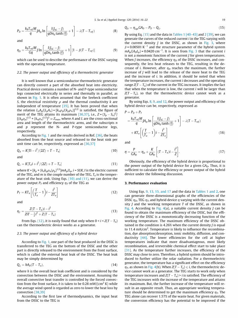
Fig. 5. Curves of the maximum efficiency gmax of the hybrid system varying withtemperature of the DSSC for given values of b, where the horizontal line indicatesthe efficiency of the DSSC at the reference temperature condition. TL and TH are twooperating temperatures of the hybrid device when the efficiency of the hybriddevice is equal to that of the DSSC. The values of the relevant parameters are thesame as those used in Fig. 3.
0.000 0.002 0.004 0.006 0.008
332
336
340
344
348
β0
T (K
)
β (K-1)
TH
TL
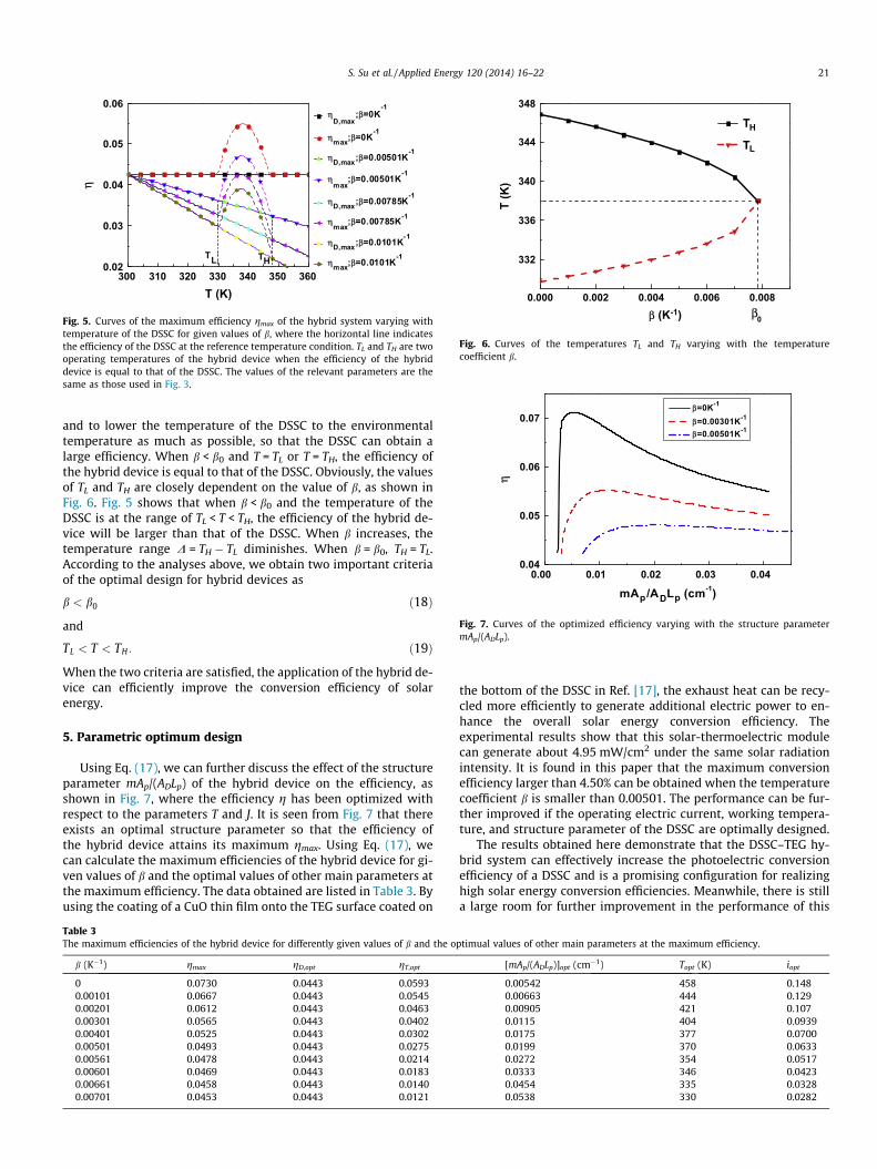
Fig. 6. Curves of the temperatures TL and TH varying with the temperaturecoefficient b.
0.00 0.01 0.02 0.03 0.040.04
0.05
0.06
0.07
η
mAp/ADLp (cm-1)
β=0K-1
β=0.00301K-1
β=0.00501K-1
Fig. 7. Curves of the optimized efficiency varying with the structure parametermAp/(ADLp).
S. Su et al. / Applied Energy 120 (2014) 16–22 21
and to lower the temperature of the DSSC to the environmentaltemperature as much as possible, so that the DSSC can obtain alarge efficiency. When b < b0 and T = TL or T = TH, the efficiency ofthe hybrid device is equal to that of the DSSC. Obviously, the valuesof TL and TH are closely dependent on the value of b, as shown inFig. 6. Fig. 5 shows that when b < b0 and the temperature of theDSSC is at the range of TL < T < TH, the efficiency of the hybrid de-vice will be larger than that of the DSSC. When b increases, thetemperature range D = TH � TL diminishes. When b = b0, TH = TL.According to the analyses above, we obtain two important criteriaof the optimal design for hybrid devices as
b < b0 ð18Þ
and
TL < T < TH: ð19Þ
When the two criteria are satisfied, the application of the hybrid de-vice can efficiently improve the conversion efficiency of solarenergy.
5. Parametric optimum design
Using Eq. (17), we can further discuss the effect of the structureparameter mAp/(ADLp) of the hybrid device on the efficiency, asshown in Fig. 7, where the efficiency g has been optimized withrespect to the parameters T and J. It is seen from Fig. 7 that thereexists an optimal structure parameter so that the efficiency ofthe hybrid device attains its maximum gmax. Using Eq. (17), wecan calculate the maximum efficiencies of the hybrid device for gi-ven values of b and the optimal values of other main parameters atthe maximum efficiency. The data obtained are listed in Table 3. Byusing the coating of a CuO thin film onto the TEG surface coated on
Table 3The maximum efficiencies of the hybrid device for differently given values of b and the o
b (K�1) gmax gD,opt gT,opt
0 0.0730 0.0443 0.05930.00101 0.0667 0.0443 0.05450.00201 0.0612 0.0443 0.04630.00301 0.0565 0.0443 0.04020.00401 0.0525 0.0443 0.03020.00501 0.0493 0.0443 0.02750.00561 0.0478 0.0443 0.02140.00601 0.0469 0.0443 0.01830.00661 0.0458 0.0443 0.01400.00701 0.0453 0.0443 0.0121
the bottom of the DSSC in Ref. [17], the exhaust heat can be recy-cled more efficiently to generate additional electric power to en-hance the overall solar energy conversion efficiency. Theexperimental results show that this solar-thermoelectric modulecan generate about 4.95 mW/cm2 under the same solar radiationintensity. It is found in this paper that the maximum conversionefficiency larger than 4.50% can be obtained when the temperaturecoefficient b is smaller than 0.00501. The performance can be fur-ther improved if the operating electric current, working tempera-ture, and structure parameter of the DSSC are optimally designed.
The results obtained here demonstrate that the DSSC–TEG hy-brid system can effectively increase the photoelectric conversionefficiency of a DSSC and is a promising configuration for realizinghigh solar energy conversion efficiencies. Meanwhile, there is stilla large room for further improvement in the performance of this
ptimual values of other main parameters at the maximum efficiency.
[mAp/(ADLp)]opt (cm�1) Topt (K) iopt
0.00542 458 0.1480.00663 444 0.1290.00905 421 0.1070.0115 404 0.09390.0175 377 0.07000.0199 370 0.06330.0272 354 0.05170.0333 346 0.04230.0454 335 0.03280.0538 330 0.0282

22 S. Su et al. / Applied Energy 120 (2014) 16–22
hybrid system by further optimization. Future experimental workswould be conducted to quantitatively verify the present model.Dye molecules need to be further studied for alleviating tempera-ture effects on the performance of the DSSC. The experimentalmethods described in Refs. [21,43] will be used to prepare the pho-toelectrode film, and then a solar selective absorber will be placedin between the DSSC and the TEG. For a thermoelectric generator,Bi2Te3 material can be used because of its excellent performance atthe low temperature range. With illumination, the J–V characteris-tics of the hybrid system will be measured and quantitatively com-pared with the theoretical results.
6. Conclusions
An electric and thermal model of the hybrid device consisting ofa DSSC and a semiconductor thermoelectric generator is estab-lished. The maximum efficiency of the hybrid device is calculatedand the optimally working states of the hybrid device are deter-mined. Temperature effects on the performance of the DSSC andhybrid device are analyzed in detail and compared. The optimumcriteria of the parametric design are obtained. These results ob-tained here may provide some guidance for the optimum designof practical DSSC–TEG hybrid devices.
Acknowledgments
This work has been supported by the National Natural ScienceFoundation (No. 11175148), 973 Program (No. 2012CB619301),and the Fujian Natural Science Foundation (No. 2012J05097), Peo-ple’s Republic of China.
References
[1] O’regan B, Grätzel M. A low-cost, high-efficiency solar cell based on dye-sensitized. Nature 1991;353:737–40.
[2] Liu Y, Wang H, Shen H, Chen W. The 3-dimensional dye-sensitized solar celland module based on all titanium substrates. Appl Energy 2010;87:436–41.
[3] Grätzel M. Photovoltaic and photoelectrochemical conversion of solar energy.Phil Trans R Soc A 2007;365:993–1005.
[4] Grätzel M. Mesoscopic solar cells for electricity and hydrogen production fromsunlight. Chem Lett 2005;34:8–13.
[5] Li M, Liu Y, Wang H, Shen H. Synthesis of TiO2 submicro-rings and theirapplication in dye-sensitized solar cell. Appl Energy 2011;88:825–30.
[6] McConnell RD. Assessment of the dye-sensitized solar cell. Renew Sust EnergyRev 2002;6:273–95.
[7] Guo XZ, Zhang YD, Qin D, Luo YH, Li DM, Pang YT, et al. Hybrid tandem solarcell for concurrently converting light and heat energy with utilization of fullsolar spectrum. J Power Sources 2010;195:7684–90.
[8] Bisquert J, Vikhrenko VS. Interpretation of the time constants measured bykinetic techniques in nanostructured semiconductor electrodes and dye-sensitized solar cells. J Phys Chem B 2004;108:2313–22.
[9] Bisquert J, Fabregat-Santiago F, Kalyanasundaram K. Dye-sensitized solarcells. Boca Raton: CRC Press; 2010.
[10] Horiuchi T, Miura H, Sumioka K, Uchida S. High efficiency of dye-sensitizedsolar cells based on metal-free indoline dyes. J Am Chem Soc2004;126:12218–9.
[11] Zhang W, Zhu R, Liu B, Ramakrishna S. High-performance hybrid solar cellsemploying metal-free organic dye modified TiO2 as photoelectrode. ApplEnergy 2012;90:305–8.
[12] Wang X, Li H, Liu Y, Zhao W, Liang C, Huang H, et al. Hydrothermal synthesis ofwell-aligned hierarchical TiO2 tubular macrochannel arrays with large surfacearea for high performance dye-sensitized solar cells. Appl Energy2012;99:198–205.
[13] Kang HY, Wang HP. Cu@C dispersed TiO2 for dye-sensitized solar cellphotoanodes. Appl Energy 2012;100:144–7.
[14] Meng QB, Takahashi K, Zhang XT, Sutanto I, Rao TN, Sato O, et al. Fabrication ofan efficient solid-state dye-sensitized solar cell. Langmuir 2003;19:3572–4.
[15] Jeong WS, Lee JW, Jung S, Yun JH, Park NG. Evaluation of external quantumefficiency of a 12.35% tandem solar cell comprising dye-sensitized and CIGSsolar cells. Sol Energy Mater Sol C 2011;95:3419–23.
[16] Ahn KS, Yoo SJ, Kang MS, Lee JW, Sung YE. Tandem dye-sensitized solar cell-powered electrochromic devices for the photovoltaic-powered smart window.J Power Sources 2007;168:533–6.
[17] Chang H, Kao M, Cho K, Chen S, Chu K, Chen C. Integration of CuO thin filmsand dye-sensitized solar cells for thermoelectric generators. Curr Appl Phys2011;11:S19–22.
[18] Wang N, Han L, He H, Parkb NH, Koumoto K. A novel high-performancephotovoltaic-thermoelectric hybrid device. Energy Environ Sci2011;4:3676–9.
[19] Södergren S, Hagfeldt A, Olsson J, Lindquist SE. Theoretical models for theaction spectrum and the current–voltage characteristics of microporoussemiconductor films in photoelectrochemical cells. J Phys Chem1994;98:5552–6.
[20] Gómez R, Salvador P. Photovoltage dependence on film thickness and type ofillumination in nanoporous thin film electrodes according to a simple diffusionmodel. Sol Energy Mater Sol C 2005;88:377–88.
[21] Nazeeruddin MK, Kay A, Rodicio I, Humphry-Baker R, Mueller E, Liska P, et al.Conversion of light to electricity by cis-X2bis (2,20-bipyridyl-4,40-dicarboxylate) ruthenium(II) charge-transfer sensitizers (X = Cl�, Br�, I�,CN�, and SCN�) on nanocrystalline titanium dioxide electrodes. J Am ChemSoc 1993;115:6382–90.
[22] Grätzel M. Dye-sensitized solar cells. J Photochem Photobiol C 2003;4:145–53.[23] Grätzel M. Conversion of sunlight to electric power by nanocrystalline dye-
sensitized solar cells. J Photochem Photobiol A 2004;164:3–14.[24] Ni M, Leung MKH, Leung DYC, Sumathy K. An analytical study of the porosity
effect on dye-sensitized solar cell performance. Sol Energy Mater Sol C2006;90:1331–44.
[25] Ni M, Leung MKH, Leung DYC, Sumathy K. Theoretical modeling of TiO2/TCOinterfacial effect on dye-sensitized solar cell performance. Sol Energy MaterSol C 2006;90:2000–9.
[26] Ni M, Leung MKH, Leung DYC. Theoretical modelling of the electrode thicknesseffect on maximum power point of dye-sensitized solar cell. Can J Chem Eng2008;86:35–42.
[27] Lee JJ, Coia GM, Lewis NS. Current density versus potential characteristics ofdye-sensitized nanostructured semiconductor photoelectrodes. 2. Simulation.J Phys Chem B 2004;108:5282–93.
[28] Berginc M, Opara Krašovec U, Jankovec M, Topic M. The effect of temperatureon the performance of dye-sensitized solar cells based on a propyl-methyl-imidazolium iodide electroly. Sol Energy Mater Sol C 2007;91:821–8.
[29] Ting CC, Chao WS. Measuring temperature dependence of photoelectricconversion efficiency with dye-sensitized solar cells. Measurement2010;43:1623–7.
[30] Sebastián PJ, Oleac A, Campos J, Toledob JA, Gamboa SA. Temperaturedependence and the oscillatory behavior of the opto-electronic properties ofa dye-sensitized nanocrystalline TiO2 solar cell. Sol Energy Mater Sol C2004;81:349–61.
[31] Toivola M, Peltokorpi L, Halme J, Lund P. Regenerative effects by temperaturevariations in dye-sensitized solar cells. Sol Energy Mater Sol C2007;91:1733–42.
[32] Lee KJ, Kim JH, Kim HS, Shin D, Yoo D, Kim H. A study on a solar simulator fordye sensitized solar cells. Int J Photoenergy 2012;2012:834347.
[33] Skoplaki E, Palyvos JA. On the temperature dependence of photovoltaicmodule electrical performance: a review of efficiency/power correlations. SolEnergy 2009;83:614–24.
[34] Perlman J, McNamara A, Strobino D. Analysis of PV system performance versusmodelled expectations across a set of identical PV systems. In: Proc ISES SolWorld Cong. ‘‘Bringing Water to the World, August 6–12, Orlando, Florida;2005.
[35] Goldsmid HJ. Introduction to thermoelectricity. Verlag Berlin,Heidelberg: Springer; 2010.
[36] Chen J, Lin B, Wang H, Lin G. Optimal design of a multi-couple thermoelectricgenerator. Semicond Sci Technol 2000;15:184–8.
[37] Chen X, Chen L, Guo J, Chen J. An available method exploiting the waste heat ina proton exchange membrane fuel cell system. Int J Hydrogen Energy2011;36:6099–104.
[38] Chow TT, He W, Ji J. Hybrid photovoltaic-thermosyphon water heating systemfor residential application. Sol Energy 2006;36:298–306.
[39] Rowe DM. Handbook of thermoelectrics: macro to nano. Boca Raton: CRC;2005.
[40] Rothenberger G, Fitzmaurice D, Gratzel M. Spectroscopy of conduction-bandelectrons in transparent metal-oxide semiconductor-films: opticaldetermination of the flat-band potential of colloidal titanium-dioxide films. JPhys Chem 1992;96:5983–6.
[41] Ferber J, Luther J. Modeling of photovoltage and photocurrent in dye-sensitized titanium dioxide solar cells. J Phys Chem B 2001;105:4895–903.
[42] Gomez R, Salvador P. Photovoltage dependence on film thickness and type ofillumination in nanoporous thin film electrodes according to a simple diffusionmodel. Sol Energy Mater Sol C 2005;88:377–88.
[43] Dloczik L, Ileperuma O, Lauermann I, Peter LM, Ponomarev EA, Redmond G,et al. Dynamic response of dye-sensitized nanocrystalline solar cells:characterization by intensity modulated photocurrent spectroscopy. J PhysChem B 1997;101:10281–9.
[44] Atkins PW. Physical chemistry. 5th ed. Oxford, Melbourne, Tokyo: OxfordUniversity Press; 1994.