thermal energy storage tank design
DESCRIPTION
Thermal Energy Storage Tank DesignTRANSCRIPT

Thermal Energy Storage (TES)Tank Design
Presented by
Jim Ford
Business Development Manager
Chicago Bridge & Iron Co.
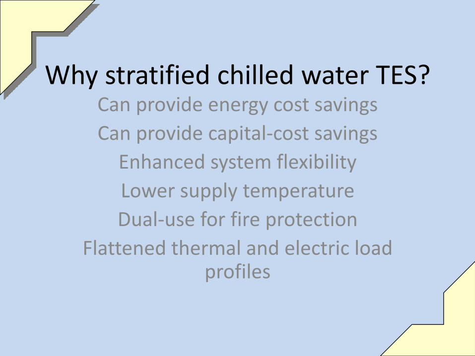
Why stratified chilled water TES?Can provide energy cost savingsCan provide capital‐cost savingsEnhanced system flexibilityLower supply temperatureDual‐use for fire protection
Flattened thermal and electric load profiles

First, Some BasicsHow Stratification Works
↑ T, ↓ ρ
Observed in isolated lakes and ponds, water left undisturbed tends to formstratified layers due to gravity acting on a density gradient

Water Density vs. Temperature
Stratification in TES systems relies on the relationship between densityand temperature to maintain separation between hot and cold fluid

Making Stratification WorkStratified thermal storage can accommodate almost any temperature difference, although the storage volume required is minimized with larger delta‐T
Thermal diffusion between the hot and cold fluid is confined to the interface region called the thermocline
The key to leveraging this phenomenon for thermal storage is creating stratified layers and keeping the stratification intact

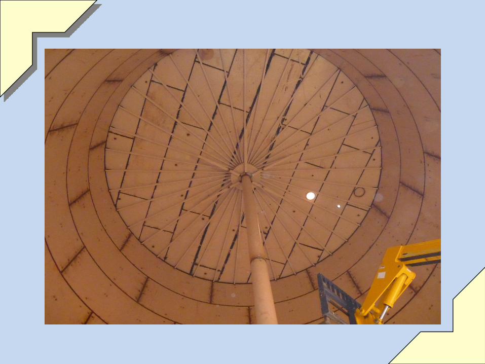
Thermal Energy Storage Tank Components
Fill/Drain Overflow
Manhole
Manhole
Lower Diffuser
Center Column
Openings in Center Column: allow flow in/out of tank
Upper Diffuser
Lower DiffuserInlet & outlet
Roof Vent

Discharge and Recharge Flow Schematics
Thermocline
Discharge CycleRecharge Cycle

Chiller
Return from Load
Supply to Load
Recharge Cycle
Hold Cycle
Discharge Cycle
Chiller
Return from Load
Supply to Load
Chiller
Return from Load
Supply to Load
ChillerChiller
Trickle ChargeSystem Shutdown
Chilled Water Storage Cycles

TES Tank Structural Design LimitsLimitation Governed by
Maximum Shell Height Process conditions (pump suction pressure)Soil Conditions (Geotechnical Report)Tank shell thickness considerationsSeismic design, sloshing waveAesthetics
Minimum Shell Height Tank performance/efficiency
Maximum Roof Height ClearancesLocal building codesAesthetics
Maximum Diameter Area available – also consider construction requirements
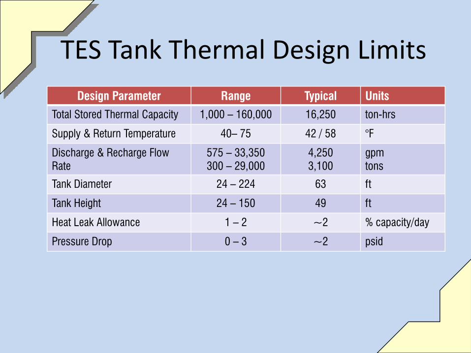
TES Tank Thermal Design Limits
Design Parameter Range Typical Units
Total Stored Thermal Capacity 1,000 – 160,000 16,250 ton-hrs
Supply & Return Temperature 40– 75 42 / 58 °F
Discharge & Recharge Flow Rate
575 – 33,350300 – 29,000
4,2503,100
gpmtons
Tank Diameter 24 – 224 63 ft
Tank Height 24 – 150 49 ft
Heat Leak Allowance 1 – 2 ~2 % capacity/day
Pressure Drop 0 – 3 ~2 psid

TES Design Standards, Codes, Guides
ASHRAE2005 HVAC Fundamentals Handbook2007 HVAC Applications Handbook, Chapter 34,
Thermal StorageDesign Guide for Cool Thermal storageStandard 150, Method for Testing the Performance of
Cool Storage Systems

TES Design Standards, Codes, Guides
AWWA – American Water Works AssociationD100-05 Welded Steel Tanks for Water StorageD102-06 Painting Steel Water Storage Tanks
ASMEB31.1 – Code for Pressure Piping- Power Piping
NFPA – National Fire Protection AssociationStandard for Water Tanks for Private Water Protection
API – American Petroleum InstituteStandard 650 – Welded Steel Tanks for Oil Storage
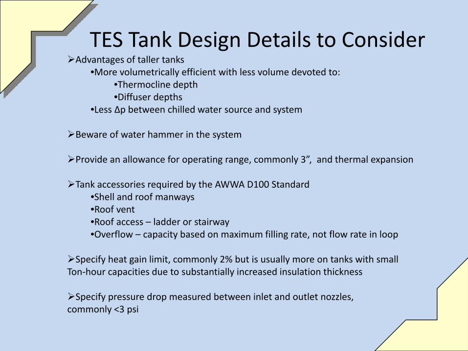
TES Tank Design Details to ConsiderAdvantages of taller tanks
•More volumetrically efficient with less volume devoted to:•Thermocline depth•Diffuser depths
•Less Δp between chilled water source and system
Beware of water hammer in the system
Provide an allowance for operating range, commonly 3”, and thermal expansion
Tank accessories required by the AWWA D100 Standard•Shell and roof manways•Roof vent•Roof access – ladder or stairway•Overflow – capacity based on maximum filling rate, not flow rate in loop
Specify heat gain limit, commonly 2% but is usually more on tanks with small Ton‐hour capacities due to substantially increased insulation thickness
Specify pressure drop measured between inlet and outlet nozzles, commonly <3 psi


TES Tank Instrumentation
Thermowells forTemperature sensors
Roof nozzleFor level gauge/switch
Supply and returnTemperature Sensors, external To tank
Flow meteringis external to tank


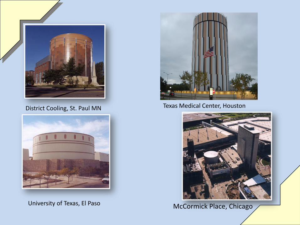
District Cooling, St. Paul MN
University of Texas, El Paso
Texas Medical Center, Houston
McCormick Place, Chicago