thermal analysis of reinforced concrete chimneys with …€¦ · · 2016-03-23reinforced...
TRANSCRIPT

Engineering Structures 75 (2014) 87–98
Contents lists available at ScienceDirect
Engineering Structures
journal homepage: www.elsevier .com/ locate /engstruct
Thermal analysis of reinforced concrete chimneys with fiberglass plasticliners in uncontrolled fires
http://dx.doi.org/10.1016/j.engstruct.2014.03.0430141-0296/� 2014 Elsevier Ltd. All rights reserved.
⇑ Corresponding author. Tel.: +1 781 255 4958.E-mail address: [email protected] (A. Agelaridou-Twohig).
Artemis Agelaridou-Twohig a,⇑, Franco Tamanini a, Hosam Ali a, Amin Adjari b, Ashkan Vaziri b
a FM Global, 1151 Boston-Providence Turnpike, Norwood, MA 02062, United Statesb Department of Mechanical and Industrial Engineering, Northeastern University, Boston, MA 02115, United States
a r t i c l e i n f o a b s t r a c t
Article history:Received 22 August 2011Revised 23 December 2013Accepted 26 March 2014Available online xxxx
Keywords:Reinforced concrete chimneyFRP linersUncontrolled fireResidual structural capacityTransient heat transfer
This paper presents a simple method to calculate fire duration and flue gas temperatures for reinforcedconcrete (RC) chimneys with fiberglass reinforced plastic (FRP) liners based on experimentally deter-mined burning characteristics of the liner material. Implementation of the method to calculate fire dura-tions and the transient heat transfer conditions is demonstrated for single- and four-liner chimneys. Aparametric study is carried out for chimney designs and geometries ranging from 100 m to 300 m inheight and 7 m to 40 m in diameter, with 1–4 liners and varying opening configurations. The resultsare used to identify a limited number of cases for which the RC chimney undergoes the most extremereduction in its post-fire residual strength. Analytical estimations of the chimney residual strength afterthe fire are obtained using a method established based on the procedure outlined in the American Con-crete Institute (ACI) 307 Standard for chimney strength calculations. Calculations for a series of criticalconfigurations of RC chimneys, with FRP liner geometries within the practical design limits detailed inthis paper, show that the post-fire structural capacity of the chimneys would not lead to catastrophic fail-ures especially because the chimney is not expected to see other high design lateral loads such as wind orearthquake simultaneously.
� 2014 Elsevier Ltd. All rights reserved.
1. Introduction
Fiberglass reinforced plastic (FRP) liners, schematically shownin Fig. 1, are used to protect the shell of reinforced concrete (RC)chimneys from the corrosive effects of the flue gases. The FRPmaterial is combustible and employment in concrete chimneysincreases the risk of uncontrolled fire. Smoking or hot work insidethe chimney during maintenance, ignition of stored flammablematerials at the base of the chimney or some abnormal conditionin the upstream system could lead to a fire in the FRP liner. InMarch 2006 a fire occurred in a reinforced concrete chimney of apower plant that was being retrofitted with an FRP liner [1].Reports mention that the fire spread to all but the top 3 m of the300-m high chimney. The fire broke out at night and was fullyextinguished by the afternoon of the following day. Though the firedestroyed the liner, the concrete chimney did not collapse. Eventhough there have been no major collapse-following-fire incidents,the effects of a liner fire and the possibility of chimney collapseneed to be investigated due to the expanding usage of FRP linersin reinforced concrete chimneys.
Knowledge of the fire characteristics is essential in estimatingthe reduction of structural capacity of the chimney during the fire,as well as its post-fire residual strength because, in general, pro-longed exposure of the chimney shell to high temperatures willdegrade the concrete strength and depending on the level andduration of exposure it can jeopardize the structural integrity ofthe RC chimney [2–10]. To study the thermal behavior of RC chim-neys with FRP liners, three fire scenarios, shown schematically inFig. 1, were considered:
� The first scenario covers burning of a pile of FRP rubble createdby a fire that started on the liners and caused them to collapseat the bottom of the RC chimney. Assuming that the chimney’sbottom opening that allows the incoming airflow is not closedor blocked during the fire, it is expected that the incoming airwill push the flames towards one side of the chimney causinglocalized heating of the chimney wall.� In the second scenario, the FRP remains structurally sound dur-
ing a fire outside a liner or liners. Part of the heat released bysuch a fire will be carried out of the chimney by the air flowingbetween the liner and the concrete shell, and part of it will heatup the chimney wall. The average surface area of the FRP that isinvolved in the fire at any given time affects the duration of the

Fig. 1. Fire scenarios for chimneys with FRP liners.
88 A. Agelaridou-Twohig et al. / Engineering Structures 75 (2014) 87–98
fire as well as the average temperature increase of the airflowing through the chimney. If the liner breaks and causes‘‘blockage’’ of the airflow, it is conceivable that less air will flowthrough the chimney and the concrete wall will be exposed tohigher average gas temperatures. In studying this scenario, itwas conservatively assumed that even for restricted airflowconditions, there is enough oxygen for well-ventilated burning.� Fire in the third scenario develops and propagates inside a liner
or liners without penetrating to the outside and without linercollapse. In this case, the fire is contained within the liner andthe air in the gap between the liner and the concrete wall doesnot experience any major temperature increase. Thus, this sce-nario is unlikely to cause considerable reduction in chimneystrength and is not analyzed further.
2. Outline of approach
The main objective was to determine the reduced structuralcapacity of the critical chimney and fire configurations, and checkif chimneys with FRP liner geometries that are within the practicaldesign limits will have enough post-fire residual capacity to carrythe design loads. This requires a stress analysis procedure summa-rized in Section 8 using a method [11], established based on theanalyses outlined in the ACI 307 Standard [12]. The stress analysisrequired ways to calculate the average fire duration and the aver-age temperature of the gas inside the chimney, discussed inSections 4 And 5, respectively, established based on burning char-acteristics of the FRP liner material determined experimentally asdescribed in Section 3.
The approach was applied, as presented in Section 6, to twocases of transient heat transfer analyses across the concrete wallfor 165-m high single-liner and 240-m high four-liner chimneys.Schematics of the two chimneys with representative dimensionsare shown in Fig. 2. Extensive parametric studies for chimneygeometries ranging from 100 m to 300 m in height and 7 m to40 m in diameter, with multi liners and varying opening configura-tions were performed to identify critical configurations based onthe severity of the fire conditions. They are described in Section 7.
3. Burning characteristics of FRP liner material
An experimental study of a salvaged chimney liner showed thatthis material burns, a illustrated in Fig. 3, in two stages: an initialrapid flare-up of the resin-rich top layer (stage I) followed by adie-back to a steady-state lower intensity fire (stage II).
The average heat release rate per unit area of the liner materialfor the duration of the fire, �_q00 (kW/m2), can be calculated as a timeweighted average by Eq. (1).
�_q00 ¼_QIAI� tI þ
_QIIAII� tII
tI þ tIIð1Þ
The symbols _Q and A in Eq. (1) correspond to the net heat releaserate (kW) and the burned area (m2) respectively, while t is the dura-tion of each burning phase (s), and subscripts I and II correspond tothe two stages of burning. The test data used to calculate averageheat release rates for three Parallel Panel [13,14] experiments basedon Eq. (1) are shown in Table 1.
The efficiency of FRP combustion was quantified in terms of aneffective heat release parameter DHc,PP (kJ/kg). As shown in Eq. (2),this parameter depends on the average heat release rate per unitarea of FRP for the duration of the fire, �_q00, which is calculated byEq. (1), the duration of the two burning stages tI and tII (s), theFRP thickness X (m) and density q (kg/m3).
DHc;PP ¼�_q00 � ðtI þ tIIÞ
X � q ð2Þ
The FRP thickness used in the experiments was X = 1.58 cm,which is a typical thickness of industrial FRP liners (1.3–2.5 cmor 0.5–1.0 in.) [15]. The density of FRP was q = 1678 kg/m3.
Data used for the calculation of the effective heat releaseparameter are also given in Table 1. For the purposes of this studythe calculated values of the average heat release rate per unit areaof the liner material for the duration of the fire and the effectiveheat release parameter were rounded up to representative valuesof �_q00 ¼ 75 kW/m2 and DHc,PP = 8 MJ/kg, respectively. These valuesare consistent with published data [16].

Fig. 2. Dimensions of single and four-liner chimneys.
Fig. 3. Parallel Panel configuration and typical burning stages of FRP liner [13,14].
A. Agelaridou-Twohig et al. / Engineering Structures 75 (2014) 87–98 89
4. Average fire duration
The effective heat release parameter, DHc,PP (kJ/kg), representsthe amount of heat released when a unit mass of FRP burns inthe Parallel Panel configuration. The average heat release rate, �_q00
(kW/m2), represents the rate that heat is released from a unit areaof the liner per second. Thus, the average fire duration can be cal-culated by dividing the effective heat release parameter multipliedby the mass of the FRP by the heat release rate multiplied by the
surface area of the FRP, as shown by Eq. (3). The parameters q(kg/m3), V (m3) and Af (m2), used in Eq. (3) represent the density,volume and average surface area of the FRP liner involved in thefire.
tfire ¼DHc;PP � q � V
�_q00 � Af
¼ DHc;PP � q�_q00
� �� V
Af
� �
¼ ½179;000 ðs=mÞ� � VAfðmÞ
� �ð3Þ

Table 1Calculation of average heat release rate and effective heat release parameter based onParallel Panel test data [13,14].
Parallel Panel data Experiment
1 2 3
Source fire (kW) 360 360 150Measured heat release rate – stage I (kW) 3800 3900 900Measured heat release rate – stage II (kW) 730 670 402Flame spread – stage I (m) 4.87 4.87 4.87Flame spread – stage II (m) 2.40 2.30 1.80Fire duration – stage I (s) 84 92 169Fire duration – stage II (s) 2220 2160 3360Steady state flame duration (min) 37 36 56Heat release rate –stage I (kW) 3440 3540 750Heat release rate –stage II (kW) 370 310 252Burnt area – stage I (m2) 10.4 10.4 10.4Burnt area – stage II (m2) 5.14 4.92 3.85Average heat release rate per unit area of FRP lining
(kW/m2)81.5 74.3 65.7
Fire duration (s) as the sum of stages I and II 2304 2252 3529Heat of combustion for FRP in Parallel Panel (MJ/kg) 7.08 6.31 8.75
90 A. Agelaridou-Twohig et al. / Engineering Structures 75 (2014) 87–98
5. Average temperature of gases inside the chimney
5.1. Rubble fire
During an FRP rubble fire at the base of the chimney in first sce-nario of Fig. 1, the average temperature of the gas near the concreteshell will be close to the flame temperature. Assuming a reasonablylarge fire, giving out 150 kW/m2 which is twice as much as theobserved heat flux for FRP liners of typical thickness burning in aParallel Panel configuration summarized in Table 1, an estimatefor the flame temperature, Tf, can be obtained by assuming radia-tion as the main heat transfer mechanism the Stefan–Boltzmannlaw:
_q00 ¼ r � ðT4f � T4
1Þ ) Tf ¼_q00
rþ T4
1
� �0:25
ð4Þ
where r is the Stefan–Boltzmann constant equal to 5.67 � 10�8
W/m2 K4. Based on this relationship, a flame gas temperature ofabout 1000 �C was considered a reasonable conservative estimatefor the flame gases next to the concrete wall.
Fig. 4 shows the internal hint and external hext, thermal bound-ary conditions on the respective surfaces of the reinforced concreteshell surrounding the burning liner or liners. In the figure, the aver-age temperature of the air inside the chimney and the ambienttemperature are denoted by Tg and T1. Appendix A provides heat
Fig. 4. Thermal boundary conditions on the chimney walls.
transfer correlations that can be used to calculate the internaland external heat transfer coefficients hint and hext, respectively.
5.2. Fire outside liners
For a fire that burns on the outside surface of the liner as shownfor the second scenario in Fig. 1, the average temperature of the airinside the chimney, Tg, over the duration of the fire depends onthe flow rate in the gap between the liner and the concrete wall,_m (kg/s). The flow rate for a chimney of height, H, can be estimated
from Eq. (5) (see Appendix B for the derivation).
_m ¼Ao � qgffiffiffiffiffiffiffiffiffiffiffiffiffiffiffiffiffiffiffiffiffiffiffiffiffiffiffiffiffiffiffiffiffiffiffiffiffi
C1 þ C2 � ðAo=AiÞ2q �
ffiffiffiffiffiffiffiffiffiffiffiffiffiffiffiffiffiffiffiffiffiffiffiffiffiffiffiffiffiffiffiffiffiffiffiffiffiffiffiffi2 � g � H � ðTg � T1Þ
T1
sð5Þ
where qg is the average density of air in the chimney, g is the grav-itational acceleration, and Ao and Ai are the outlet and inlet areas.The outlet area is calculated by subtracting the area inside the linersfrom the area inside the concrete shell. The inlet area is the totalarea of the chimney wall openings excluding the flue gas ducts.The mathematical expressions for constants C1 and C2, are describedin Appendix B.
The convective heat flux from a fire involving FRP causes thetemperature of the air in the gap between the concrete and the lin-ers to rise. Assuming that the average temperature of the air in thechimney during the fire is Tg (K) and the specific heat of air is cp
(J/kg K), the heat flux can be written as:
�_q00 ¼_m � cp � ðTg � T1Þ
Afð6Þ
The average air temperature Tg in K can be calculated by trial anderror from Eqs. (5) and (6) as a function of the average area of theFRP involved in the fire,ffiffiffiffiffiffiffiffiffiffiffiffiffiffiffiffiffiffiffiffiffiffiffiðTg � T1Þ3
T2g � T1
vuut ¼ C3 � Af ð7Þ
where the constant C3 (with units of m�2) is given by:
C3 ¼�_q00 � R
cp � Ao � P�
ffiffiffiffiffiffiffiffiffiffiffiffiffiffiffiffiffiffiffiffiffiffiffiffiffiffiffiffiffiffiffiffiffiffiffiffiffiC1 þ C2 � ðAo=AiÞ2
2 � g � H
sð8Þ
6. Chimneys with single and multiple liners
The calculations provided in this section were based on theassumption that the air inside the chimney is at an average tem-perature, and localized heating effects were ignored. It was alsoassumed that there is no insulation between the liner and the outerconcrete wall of the chimney so that the air is allowed to flowfreely through that gap. Finally, the air flowing through the chim-ney was assumed to provide sufficient oxygen to sustain the fireuntil the full volume of the FRP liner was consumed. The fireburned at an average ‘steady’ rate releasing a steady amount ofheat per unit area without exhibiting a decay phase until the entirevolume of the FRP liner was consumed, at which point, the temper-ature of the air inside the chimney dropped to 27 �C. Schematics ofthe single and four-liner chimneys are shown in Fig. 2 and the listof the various parameters used in the calculations is given inTable 2.
The effect of the large construction opening at the bottom of thechimney was taken into account and both options of ‘unobstructedopening’ and ‘obstructed opening’ were considered for one of theexamples (single-liner chimney). The analysis for the four-linerchimney assumed that the construction opening at the base ofthe chimney was open, allowing enough airflow between the liners

Table 2List of parameters used for calculations of the single and four-liner chimneys.
Parameter Symbol Formula/reference Unit Valuesingle-liner
Value four-liner
Chimney height H Fig. 2 m 165 238Chimney inner diameter D Fig. 2 m 12.5 24FRP liner thickness (average) X Ref. [13] m 0.015FRP liner outer diameter d Fig. 2 m 9.5 8Top opening Atop p � D2/4 � p � d2/4 m2 53 256Other openings Adr Fig. 2 m2 105 158Total inlet area (incl. Adr) Ai Fig. 2 m2 127 158Total outlet area Ao Atop m2 53 256Hydraulic diameter DH 4�Ao
p�ðDþdÞm 3.05 5.84
Discharge coefficient Cd Refs. [17,18] – 0.65Outside air temperature T1 – �C 27Gravitational acceleration g – m/s2 9.81Gas constant for dry air R Ref. [17] J/kg K 287Density of air @ Tg (�C) qg qg = Patm/R � Tg kg/m3 f(Tg)Specific heat of air (specific heat of dry air assumed to be temperature-independent) cp Ref. [17] J/kg K 1000Length of short liner L1 Fig. 2 m 129 224Length of long liner L2 N/A 230Outside area of liner A1o p � d � L1 m2 �3850 Short �5600
A2o N/A Long �5800Total exposed area of FRP AFRP A1o m2 �3850 �22,700Total flame spread area Af Some % of AFRP m2 VariableHeat release rate per unit area of FRP �_q00 Experimental data kW/m2 75
Effective heat release parameter of FRP in RC chimney DHc,RCC Experimental data kJ/kg 8000
A. Agelaridou-Twohig et al. / Engineering Structures 75 (2014) 87–98 91
and the concrete shell to provide the necessary oxygen to sustain afire involving on average 100% of the surface area of the FRP. Toinclude the effect of additional obstructions on the airflow in theair gap between the concrete shell and the liner, for the single-linerchimney we assumed 2 full support platforms with grillage com-prising 60% free area, while for the taller, four-liner chimney weassumed 4 levels of grillage comprising of 80% free area.
Depending on the average surface area of the FRP that is involvedin the fire, the average air temperature between the chimney and theliners varies and as a consequence the density of the air changes.Fig. 5A shows the variation of the air velocity and density for averageair temperatures up to 1000 �C for all types of chimneys. Fig. 5Bshows the external and internal heat transfer coefficients for varyingtemperatures. The correlations used for this calculation are given inAppendix A. The plots show that the external heat transfer coeffi-cient, which is the same for either a single or a four-liner chimney,is almost constant �5 W/m2 K for wall temperatures greater than100 �C. The internal heat transfer coefficient also shown in Fig. 5B,for a single-liner chimney with the construction opening blockedplateaus at about 17 W/m2 K, for temperatures about 300 �C. For asingle-liner chimney with an unobstructed construction opening,it can go as high as 23 W/m2 K, while for the four-liner chimney itreaches values of about 26 W/m2 K. The internal film temperaturefor post-fire calculations is assumed to be 27 �C for both the rubbleand the steady fires. The external air temperature is assumed to be27 �C throughout the analysis.
Fig. 6 shows that for a fire in a single-liner chimney involving onaverage 100% of the area of the liner (Af = 3837 m2), if the construc-tion opening is open, the average air temperature in the chimneywill reach temperatures as high as 500 �C and the fire will lastabout 50 min. On the other hand, if the construction opening isblocked, the air in the chimney will heat up to about 630 �C. A firein a four-liner chimney involving 100% of the surface area of FRPcauses the internal air in the chimney to heat up to about 550 �Cand burns for about 50 min. Based on the same figure, fires thatinvolve less of the surface area of the liner will last longer but atthe same time will cause a lower temperature rise of the air insidethe chimney.
In the case of a rubble fire inside either a single or four-linerchimney, the duration will depend on the amount of FRP involvedin the fire at any given time. If the broken liner and the airflow
conditions at the base of the chimney allow 100% of the surfacearea of the liner to be involved in the fire then the duration willbe 50 min, similar to the steady fire.
The finite element program ABAQUS [17] was used to calculatethe transient temperature profiles across the thickness of the con-crete shell for Scenarios 1 and 2. In the finite element calculations,the thermal conductivity of the 0.508 m-thick concrete wall isassumed to be 1.72 W/mK, the density 2400 kg/m3, and the specificheat 900 J/kg K [9]. For the radiative boundary conditions, an emis-sivity value of 1.0 is conservatively assumed for the concrete. Val-ues of the heat transfer coefficients were obtained from Fig. 5B.
The calculated transient temperature profiles for a single-linerchimney subject to a Scenario 1 fire, are shown in Fig. 7A and B.Although the possibility of pieces of the liner collapsing progres-sively towards the bottom of the chimney and prolonging theduration of the fire cannot be excluded, this scenario was judgedunlikely based on observations of the condition of the materialafter fire testing [4].
The transient temperature profiles shown in Fig. 7C and D for asteady fire in a single-liner chimney typical of Scenario 2, corre-spond to the most severe case that the construction opening isblocked. The curves in Fig. 7C are calculated for different times dur-ing the fire event. Fig. 7D shows the envelope of the peak temper-atures for up to 10 h post-fire, indicating that only the inner 40% ofthe concrete thickness will be thermally affected. The temperatureof the outer 60% of the concrete shell will never rise above 50 �Ceven after 10 h from the time that the last piece of liner was burnt.
Similar to the example of the single-liner chimney, Fig. 8Athrough D correspond to the transient temperature profiles acrossthe thickness of the concrete shell of a four-liner chimney sub-jected to Scenario 1 and Scenario 2 fires.
As seen from Fig. 8A during a rubble fire burning near the baseof the chimney and lasting 50 min, the inner 40% of the concretethickness at a location of flame attachment will be subjected tohigh temperatures. However, as indicated by the envelope of peaktemperatures shown in Fig. 8B, the outer 60% of the concrete shellwill not experience temperatures above 100 �C even after 10 hfrom the time that the fire has burnt the last piece of FRP rubble.The temperature profiles across the thickness of a chimneyexposed to a fire burning on the outside of the FRP liner for50 min and causing the average temperature of the air inside the

Fig. 5. (A) Variation of average flow velocity and density with temperature of air in the single and four-liner chimneys. (B) Variation of the internal and external convectionheat transfer coefficients for the single and four-liner chimneys.
Fig. 6. Steady fire duration and average air temperatures inside the chimney for different average liner surface areas involved in the fire for the single and four-linerchimneys.
92 A. Agelaridou-Twohig et al. / Engineering Structures 75 (2014) 87–98

Fig. 7. Temperature profiles across the concrete wall of a chimney. (A) Transient temperature profiles across the concrete wall for the duration of a fire (50 min) involvingbroken pieces of FRP liner burning at the base of the chimney. The plotted profiles correspond to a location of the wall with direct flame attachment. (B) Transienttemperature profiles and peak temperatures across the concrete wall for the duration and up to 10 h after the extinction of a fire involving broken pieces of FRP liner burningat the base of the chimney. The plotted profiles correspond to a location of the wall with direct flame attachment. (C) Transient temperatures for a 50-min long steady fireoutside the liner assuming that the construction opening at the bottom of the chimney is blocked and the average area of the liner involved in the fire is 100%. (D) Transienttemperature profiles and peak temperatures across the concrete wall for the duration and up to 10 h after the extinction of the steady fire.
A. Agelaridou-Twohig et al. / Engineering Structures 75 (2014) 87–98 93
chimney to rise to 550 �C are shown in Fig. 8C. Fig. 8D shows theenvelope of the peak temperatures during and post-fire for thesame fire scenario and indicates that only the inner 40% of the con-crete thickness will be thermally affected. The temperature of theouter 60% of the concrete shell will never rise above 50 �C evenafter 10 h from the end of the fire.
7. Parametric study and critical chimney configurations
Investigation of the effect of the various geometrical parametersof the chimney design on the temperature of the internal airstream, involved a matrix of chimney configurations. The matrixwas compiled after a review of the literature for chimneys housingone to four liners [18,19] based on the following assumptions:
� The RC chimney height varied between 100 m and 300 m. Theliner height was assumed to be equal to the chimney height.� The concrete shell height to diameter ratio was assumed to be
between 5 and 15.� The average concrete shell wall thickness was assumed to be
0.5 m. Liner thickness was assumed to be 0.0158 m
� The maximum value for the FRP liner diameter was assumed tobe 15 m.� The spacing between two liners as well as between a liner and
the concrete shell was assumed to be about 2 m to ensureaccessibility for installation and maintenance.� Calculations were performed for a standard air inlet area of
30 m2 representing access doors as well as for a total inlet areaof 30 m2 plus the area of the construction opening. The area ofconstruction opening was assumed to be equal to the square ofthe sum of the inner diameter of FRP liner in meter plus 2 m.
The geometrical data for these sets of chimneys are given inTable 3 and refer to the height to diameter ratio of the concreteshell (H/D), the concrete shell inner diameter (ID), the number ofliners, the liner outer diameter (d), the air outlet area (Ao) andthe air inlet area (Ai). There are two sets of data for each chimney.The first assumes that the construction opening at the base of theconcrete column is blocked. The second assumes that the openingis available allowing increased airflow through the chimney. This isreflected in the different values for the inlet surface area Ai for thetwo cases.

Fig. 8. Temperature profiles across the concrete wall of the four-liner chimney. (A) Transient temperature profiles across the concrete wall for the duration of a fire (50 min)involving broken pieces of FRP liner burning at the base of the four-liner chimney. The plotted profiles correspond to a location of the wall with direct flame attachment.(B) Transient temperature profiles and peak temperatures across the concrete wall for the duration and up to 10 h after the extinction of a fire involving broken pieces of FRPliner burning at the base of the four-liner chimney. The plotted profiles correspond to a location of the wall with direct flame attachment. (C) Transient temperatures for a 50-min-duration fire burning outside the liners assuming that the average area of the liner involved in the fire is 100%. (D) Transient temperature profiles and peak temperaturesacross the concrete wall for the duration and up to 10 h after the extinction of the fire burning outside the liners.
94 A. Agelaridou-Twohig et al. / Engineering Structures 75 (2014) 87–98
The average temperatures in �C for the air inside the chimneysdue to a steady fire involving 100% of the surface area of the linersfor the bottom construction opening being both unobstructed aswell as blocked are shown in Table 4, where shaded shells corre-spond to impractical configurations outside the range ofassumptions.
For all the chimneys, the most critical conditions occur whenthe construction opening is blocked, since this configurationinvolves a smaller amount of air in the chimney absorbing the heatfrom the fire at any given time, and thus resulting in higher tem-peratures. For all chimney heights, the average temperature ofthe air inside the chimney is higher when the design involves morefuel (4-liner configuration).
The chimney configurations shown in Table 5 reflect the obser-vations summarized in the previous paragraph and are the mostcritical from the ones examined in the parametric study. The firecharacteristics for these critical chimney configurations are shownin Fig. 9. In this figure, the average fire temperatures of thegas inside the chimneys are plotted for fire durations of 240, 180,120, 60 and 50 min. These fire durations correspond to 0.0158m-thick liners and cases of 21%, 28%, 42%, 83% and 100% of averagesurface area of the FRP being involved in the fire at any given time.
8. Residual structural capacity of critical chimneyconfigurations
Residual strength calculations for the critical chimney configu-rations in Table 5 whose fire characteristics are shown in Fig. 10were carried out using the modified American Concrete Institute(ACI) 307 methodology presented in a recent publication [12]and the results are summarized in Table 6. For these calculations,the steel rebar density of the chimney was assumed to be 0.01and the shell thickness, tshell, was assumed to be uniform alongthe height, 0.38 m (15 in.). All of the cases presented in Table 6 cor-respond to the extreme fire condition that involves 100% of thesurface area of FRP in the fire at any given time.
Cases 1 and 2 in the table correspond to a chimney up to 200 min height and 20 m in diameter exposed to steady and rubble fires,causing the average temperature of the gas inside the chimney torise to 850 and 1000 �C respectively. The residual moment strengthof the chimney after the steady fire will be equal to 96% and theresidual axial strength will be equal to 91% of its nominal strength.If the chimney is exposed to a rubble fire its residual moment andaxial strengths will be 95% and 89% of the nominal strength,respectively.
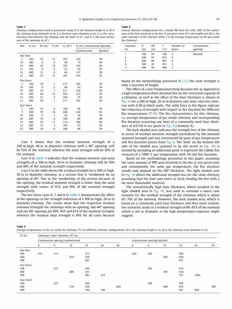
Table 3Chimney configurations used in parametric study (H is the chimney height in m, ID isthe chimney inner diameter in m, d is the liner outer diameter in m, Ao is the cross-sectional area between the chimney and the liners in m2, and Ai is the total surfacearea of the openings in m2).
H/D H (m) ID (m) d (m) Ao (m2) Ai (m2) construction opening
Unobstructed Blocked
One liner5 100 19 15 107 319 30
10 100 9 5 44 79 3010 200 19 15 107 319 3015 100 6 2 23 43 3015 200 12 8 65 137 3015 300 19 15 107 319 35
Two liners5 100 19 7 217 102 30
10 100 9 2 60 42 3010 200 19 7 217 102 3010 300 29 12 453 212 3515 200 12 3 104 57 3015 300 19 7 217 102 30
Four liners5 100 19 6 188 86 305 200 39 16 440 336 95
10 100 9 1 63 36 3010 200 19 6 188 86 4015 300 29 11 314 186 9015 200 12 2 105 47 3015 300 19 6 188 86 50
Table 5Critical chimney configurations for a steady FRP liner fire with 100% of the surfacearea of the liner involved in the fire at any given time (H is the height and OD is theouter diameter of the chimney while T is the average temperature of the gas insidethe chimney).
Chimneyno.
H(m)
OD(m)
T(�C)
Number ofliners
Constructionopening
1 100 20 766 4 Blocked2 200 20 872 43 200 40 981 44 300 20 951 15 300 30 996 2
A. Agelaridou-Twohig et al. / Engineering Structures 75 (2014) 87–98 95
Case 3 shows that the residual moment strength of a200 m-high, 40 m in diameter chimney with a 60o opening, willbe 92% of the nominal, whereas the axial strength will be 89% ofthe nominal.
Case 4 in Table 6 indicates that the residual moment and axialstrengths of a 300 m-high, 20 m in diameter chimney will be 90%and 89% of the nominal strength respectively.
Case 5 in the table shows the residual strength for a 300 m-high,30 m in diameter chimney, at a section that is ‘weakened’ by anopening of 60�. Due to the ‘weakening’ of the section because ofthe opening, the residual moment strength is lower than the axialstrength with values of 81% and 89% of the nominal strengthrespectively.
The last three cases 6, 7 and 8 in Table 6 demonstrate the effectof the openings in the strength reduction of a 300 m-high, 20 m indiameter chimney. The results show that the respective residualmoment strengths for chimneys with no opening, one 40o openingand one 60� opening are 90%, 85% and 81% of the nominal strength,whereas the residual axial strength is 89% for all cases because
Table 4Average temperatures of the air inside the chimney (�C) for different chimney configurati
H (m) Chimney’s inner diameter, ID (m)
Construction opening unobstructed
6 9 12 19 29 39
One liner100 251 313 373200 474 539300 692
Two liners100 225 244200 280 321300 382 323
Four liners100 227 430200 376 599 602300 744 766
based on the methodology presented in [11] the axial strength isonly a function of height.
The effect of a low temperature/long duration fire as opposed toa high temperature/short duration fire on the structural capacity ofa chimney, as well as the effect of the liner thickness is shown inFig. 10 for a 300-m high, 20 m in diameter one-liner concrete chim-ney with 0.38 m-thick walls. The solid lines in the figure indicatethe reduction of strength with respect to fire duration for differentfire temperatures (T �C). The fire characteristics for this chimney,i.e. average temperature of gas inside chimney and correspondingfire duration assuming one liner of a commonly used liner thick-ness of 0.0158 m are given in Fig. 9 (chimney 4).
The dark shaded area indicates the strength loss of the chimneyin terms of residual moment strength normalized by the nominalmoment strength and was constructed by pairs of gas temperatureand fire duration points from Fig. 9. The ‘kink’ on the bottom leftside of the shaded area (pointed to by the arrow in Fig. 10) isformed by including an additional point to represent the rubble firescenario of a 1000 �C gas temperature with 50 min fire duration.
Based on the methodology presented in this paper, assumingthe same amount of FRP area involved in the fire at any given timeand consequently the same gas temperature, the fire durationwould only depend on the FRP thickness. The light shaded areain Fig. 10 shows the additional strength loss for the same chimneyassuming that the liner was twice as thick, feeding the fire with alot more flammable material.
The unrealistically high liner thickness, which resulted in thelight shaded area in Fig. 10, was used to estimate a worst casescenario for the residual strength of the chimney which is about65–70% of the nominal. However, the dark shaded area, which isbased on a commonly used liner thickness and thus more realisticfire scenarios, leads to a residual strength of 80–85% of the nominalwhich is not as dramatic as the high temperature exposure mightsuggest.
ons (H is the chimney height in m, ID is the chimney inner diameter in m).
Construction opening blocked
6 9 12 19 29 39
256 349 584582 820
951
245 474363 634
757 1005
240 766460 872 981
941 996

Fig. 9. Fire characteristics for the critical chimney configurations.
Fig. 10. Residual structural capacity of a 300 m-high, 20 m in diameter chimneyafter uncontrolled fire for different fire temperatures noted in �C. The dark shadedarea marked as ‘‘Realistic Fire Scenarios’’ corresponds to fire conditions resultingfrom burning of liners with commonly used liner thickness of 0.0158 m. The lightshaded area corresponds to fire conditions resulting from an unrealistically thickliner of 0.03 m. The arrow shows the kink created by including the additional pointrepresenting the rubble fire scenario of a 1000 �C gas temperature with a 50 minfire duration.
Table 6Residual strength as a percentage of nominal strength for the critical chimney configuratthickness, T is the average temperature of the gas inside the chimney, and, tfire is the fire
Case # Openinga Chimney dimensions Fire parameters
H (m) OD (m) tshell (m) T (�C) tfire (min)
1 No 200 20 0.38 850 502 No 200 20 0.38 1000 503 60� 200 40 0.38 1000 504 No 300 20 0.38 1000 505 60� 300 30 0.38 1000 50
Effect of openings on chimneys 300 m-high, 20 m in diameter6 No 300 20 0.38 1000 507 40� 300 20 0.38 1000 508 60� 300 20 0.38 1000 50
a The ACI 307 calculation is based on the weakest region of the cross-section i.e. the levoverall circumference.
b According to ACI 307 the part of the circular cross-section subject to compression is
96 A. Agelaridou-Twohig et al. / Engineering Structures 75 (2014) 87–98
9. Summary and conclusions
A methodology was developed to calculate the thermal condi-tions in RC chimneys with FRP liners subjected to uncontrolled fire.Good estimates of the fire conditions are needed in order to calcu-late the residual strength of the chimney and the possibility of col-lapse in the case of a fire in an FRP liner or liners, since the internalsurface of the chimney can be exposed to high temperatures. Dueto the high thermal inertia of concrete, the temperature profilesacross the chimney thickness will be very steep for short fire dura-tions and the structural capacity of large RC chimneys may not suf-fer as dramatic a reduction as fire temperatures suggest.
For a given amount of FRP in the chimney with a given surfacearea, the air temperature and fire duration vary with opposingtrends. The air and gases inside the chimney will develop the high-est temperatures if 100% of the surface area of the FRP is involvedin the fire. Under this assumption, and based on experimental datafor FRP liners 0.0158-m thick, the fire was estimated to burnthrough the thickness of the material in 50 min. If on average asmaller percentage of the total FRP surface area is involved in thefire, the fire will last longer and will cause lower temperaturesinside the chimney.
Two chimney designs were used to demonstrate a calculation ofthe transient temperature profiles across the concrete thickness
ions (H is the height and OD is the outer diameter of the chimney, tshell is the shellduration).
Results
Compressive zone angle b (�) Residual strength (% of nominal strength)
Moment (%) Axial (%)
67.5 96 9167.5 95 8995 92 8994 90 89122 81 89
94 90 89113 85 89122 81 89
el that has the most openings. The opening sizes are defined in degrees as part of the
measured in degrees, as a portion of the circumference.

A. Agelaridou-Twohig et al. / Engineering Structures 75 (2014) 87–98 97
based on the fire duration and scenario-dependent average tem-perature of the air inside the chimney.
A parametric study was performed to investigate the sensitivityof the strength reduction to the chimney design. First, the averagetemperature of the gas inside the chimney for 50-min fires involv-ing 100% of the surface area of the liner was estimated according tothe developed methodology. The most critical designs from a set ofchimneys ranging from 100 to 300 m in height and 7 to 40 m indiameter with 1–4 liners and varying opening configurations wereselected by comparing the calculated temperature levels for the airinside the chimney. Then, the residual strength after the fire eventwas determined based on a modified ACI 307 methodology indicat-ing that for all the configurations examined, the strength reductionis less than 20% for both moment and axial stress, with momentstress being affected by the existence and size of openings.
The effect of a low temperature/long duration fire as opposed toa high temperature/short duration fire on the structural capacity ofa chimney, as well as the effect of the liner thickness was alsoexamined. The results show that for a given chimney, the strengthloss is relatively independent of fire duration/gas temperaturecombination. Based on the assumption of a constant burning rateper unit surface area, for a given percentage of average surface areaof liner involved in the fire, the fire duration depends on the thick-ness of the liner and thicker liners will lead to proportionallylonger fire events. However, even considering double the normallyused liner thickness, which is unrealistically high in today’s designstandards, the residual strength dropped to about 70% of the nom-inal, which for a chimney designed with a safety factor of say 1.5would not cause an immediate threat of catastrophic failure, espe-cially because the probability of the chimney being exposed toother high design lateral loads such as wind or earthquake simul-taneously, is very low.
Acknowledgement
Experimental data were obtained from unpublished work doneby FM Global colleagues Patricia Beaulieu and Archibald Tewarsonin 2008.
Appendix A. Convective heat transfer coefficients of thereinforced concrete shell
A.1. Convection on the outer surface
The free convection heat transfer coefficient can be derivedfrom the Nusselt number using the thermal conductivity of air kand the height H of the chimney as follows:
hext ¼ ðk=HÞ � ðNuÞFREE C ðA1Þ
The Nusselt number for free convection on a vertical wall can becalculated from a correlation by Churchill and Chu included in aclassic heat transfer textbook by Mills [20] involving the RayleighNumber Ra, the Prandtl Number and the Prandtl Number functionW:
Ra ¼ b � DT � g � H3=v � a > 109 for turbulent boundary layer
W ¼ 1þ 0:492Pr
� � 916
h i�169
ðNuÞFREE C ¼ 0:68þ 0:67 � ðRa �WÞ1=4 � ð1þ 1:6� 10�8 � Ra �WÞ1=12
9>>>=>>>;
ðA2Þ
where b is the volumetric coefficient of expansion of air which foran ideal gas is equal to the inverse of its absolute temperature, DTis the temperature difference between the outside of the chimneyand the ambient air, g is the gravitational acceleration equal to
9.81 m/s2, m is the kinematic viscosity and a is the thermal diffusiv-ity of air. All the air properties in Eq. (A2) should be evaluated atmean film temperature.
A.2. Convection on the inner surface heated by the fire
The convection coefficient hint for the inner surface of the con-crete shell of the chimney as shown by Eq. (A3), depends on thethermal conductivity of air k, the hydraulic diameter of the flowchannel DH and the average Nusselt number NuFORCEDC of the flowfield. The hydraulic diameter of the flow channel is given by:DH = 4 � Ao/Pw, where Ao is the average cross sectional area of theairflow inside of the chimney (i.e. the area between the linersand the concrete wall) and Pw is the wetted perimeter (i.e. theinner perimeter of the concrete wall plus the outer perimeter ofall the liners).
hint ¼ ðk=DHÞ � NuFORCEDC ðA3Þ
The forced convection Nusselt number depends on the ReynoldsNumber, Re, the Prandl Number, Pr, and the friction factor f that is afunction of the roughness of the inside surface of the chimney. Thefriction factor can be derived from Nikuradse’s formula [20]:
f ¼ 1:74þ 2:0 logDH
ks
� �� ��2
ðA4Þ
The parameter ks in Eq. (A4) is the equivalent roughness of the airflow channel inside the chimney. The value of ks for flow on con-crete surfaces was found in the literature to be about 3 mm.
For a known friction factor, the average Nusselt number can becalculated from Eq. (A5). The Reynolds Number in Eq. (A5) hasbeen written in terms of the average air velocity u (m/s), thehydraulic diameter DH (m) and the kinematic viscosity m (m2/s):
Re ¼ u�DHm
NuFORCEDC ¼ ðf=8Þ�ðRe�1000Þ�Pr1þ12:7ðf=8Þ1=2ðPr2=3�1Þ
9=; ðA5Þ
Appendix B. Pressure drop and mass flow rate of air betweenthe liners and the shell during a fire
In the event of a fire that burns on the outside of the chimneyliner or liners, it is expected that the temperature of the airbetween the liners and the concrete shell will rise. Assuming anaverage film temperature Tg over the duration of the uncontrolledfire event, in a chimney of height H, the pressure head DPth due tothermal buoyancy as a function of the density of air at ambienttemperature, q1, the average density of air in the chimney, qg,and the gravitational acceleration, g, will be:
DPth ¼ g � H � ðq1 � qgÞ ðB1Þ
The temperature-dependent density of air can be approximatedas: qg = Patm/R � Tg with the atmospheric pressure being equal toPatm = 101,325 Pa and the universal gas constant being equal toR = 287.05 J/kg K.
Some of that pressure is lost at the inlet, across the fire front, aswell as due to friction on the internal walls and across the variousobstructions in the gap between the liners and the concrete shell ofthe chimney. The pressure loss at the inlet, assuming a dischargecoefficient cd [16] can be written as:
DPi ¼1cd
� �2
� q1 �u2
i
2ðB2Þ
The value of the discharge coefficient has been measured exper-imentally [21] and is in the order of cd = 0.6–0.7. The parameter q1in Eq. (B2) is the density of cold air and the parameter ui is the inletvelocity.

98 A. Agelaridou-Twohig et al. / Engineering Structures 75 (2014) 87–98
Momentum should be conserved across the fire front. Assumingthe air velocity in the chimney before the fire front is uo and afterthe fire front is u, the pressure drop across the fire front is:
DPfire ¼ q1 � u2o � qg � u2 ðB3Þ
If the cross-section of the air flow area in the chimney is Ao and theinlet area is Ai, the conservation of mass dictates:
Ao � q1 � uo ¼ Ao � qg � u) uo ¼qg
q1� u ðB4Þ
and also
Ai � q1 � ui ¼ Ao � q1 � uo ) ui ¼Ao
Ai� uo ) ui ¼
Ao
Ai�qg
q1� u ðB5Þ
The frictional losses along the height of the chimney will be:
DPf ¼f � HDH� qg �
u2
2ðB6Þ
The friction factor f is a function of the roughness of the insidesurface of the chimney and can be derived from Nikuradse’sformula:
f ¼ 1:74þ 2:0 logDH
ks
� �� ��2
ðB7Þ
The parameter DH in Eq. (B7) is the hydraulic diameter of the flowchannel equal to DH = 4 � Ao/Pw, and the parameter ks is the equiva-lent sand-grain roughness which for concrete has a value of about3 mm [20].
To account for pressure losses due to large obstructions that canbe found in the chimney such as liner support platforms and accessladders. It is necessary to introduce another pressure drop term.Assuming that there are N levels of grillage with a certain percent-age of open area, supporting the liners inside the chimney, theminor loss coefficient n can be found in the literature and the pres-sure drop due to the internal obstructions of the flow will be:
DPf ;obstr: ¼ N � n � qg �u2
2ðB8Þ
The pressure balance in the system will lead to Eq. (B9):
DPth ¼ DPi þ DPfire þ DPf þ DPf ;obstr: ðB9Þ
Substituting Eqs. (B1), (B2), (B3), (B6), and (B8) in Eq. (B9) and usingthe conservation of mass relationships given in Eqs. (B4) and (B5),we can derive an expression of the air flow velocity in the chimney:
u ¼
ffiffiffiffiffiffiffiffiffiffiffiffiffiffiffiffiffiffiffiffiffiffiffiffi2 � g � H � DT
T1
qffiffiffiffiffiffiffiffiffiffiffiffiffiffiffiffiffiffiffiffiffiffiffiffiffiffiffiffiffiffiffiC1 þ C2 � Ao
Ai
2r ðB10Þ
The constants in Eq. (B10) are:
C1 ¼f � HDHþ N � n
� �� 2 � DT
Tg
� �
and
C2 ¼1c2
d
� �� T1
Tg
� �:
The mass flow rate can be derived from Eq. (B10) based on thecontinuity equation:
_m ¼Ao � qgffiffiffiffiffiffiffiffiffiffiffiffiffiffiffiffiffiffiffiffiffiffiffiffiffiffiffiffiffiffiffiffiffiffiffiffiffi
C1 þ C2 � ðA1=AiÞ2q �
ffiffiffiffiffiffiffiffiffiffiffiffiffiffiffiffiffiffiffiffiffiffiffiffiffiffiffiffiffiffiffiffiffiffiffiffiffiffiffiffi2 � g � H � ðTg � T1Þ
T1
sðB11Þ
References
[1] USA Today. Dramatic rescue, 1 presumed dead in W.Va. smokestack fire;March 4, 2006.
[2] Electric Power Research Institute. Technical report: ‘‘Guidelines for the use offiberglass reinforced plastic in utility FGD systems’’. EPRI-TR 101654;November 1992.
[3] Mahdy M, Speare P, Abdel-Reheem A. Effect of transient high temperature onheavyweight, high strength concrete. In: 15th ASCE Engineering MechanicsConference, Columbia University, New York, NY; June 2–5, 2002.
[4] Tsai C, Chiang C, Yang C, Chen C. Tracking concrete strength under variablehigh temperature. ACI Mater J 2005 [Title No. 102-M37].
[5] Bazant Z, Kaplan M. Concrete at high temperatures. Longman Group Limited;1996. p. 100 & 106.
[6] Annerel E, Taerwe L. Approaches for the assessment of the residual strength ofconcrete exposed to fire. International workshop: fire design of concretestructures – from materials modelling to structural performance. University ofCoimbra-Portugal; November 2007.
[7] Yang H, Lin Y, Hsiao C, Liu J. Evaluating residual compressive strength ofconcrete at elevated temperatures using ultrasonic pulse velocity. Fire Saf J2009;44:121–30.
[8] Arioz O. Effects of elevated temperatures on properties of concrete. Fire Saf J2007;42:516–22.
[9] Naus D. The effect of elevated temperature on concrete materials andstructures – a literature review. ORNL/TM-2005/553; 2005.
[10] Phan L, Carino N. Code provisions for high strength concrete strength–temperature relationships at elevated temperature. Mater Struct2003;256:91–8.
[11] Vaziri A, Adjari A, Ali H, Agelaridou Twohig A. Structural analysis of reinforcedconcrete chimneys subjected to uncontrolled fire. Eng Struct2011;33:2888–98.
[12] American Concrete Institute. Code requirements for reinforced concretechimneys (ACI 307-08) and commentary. ACI; 2008.
[13] Alpert R. Evaluation of the hazard of fire resistant materials usingmeasurements from laboratory and parallel panel tests. Fire safety scienceproceedings of the seventh international symposium. In: Evans DD, editor.International association for fire safety science; 2003. p. 41–57.
[14] Nam S, Bill Jr RG. A new intermediate-scale fire test for evaluating buildingmaterial flammability. J Fire Prot Eng 2009;19:157–76.
[15] ASTM Standard D5364-08. Standard guide for design, fabrication, and erectionof fiberglass reinforced plastic chimney liners with coal-fired units. WestConshohocken (PA): ASTM International; 2008.
[16] Beaulieu P, Dembsey N, Dorec C, Park H. Experimental results on theintermediate scale fire spread characteristics of typical FRP composites.COMPOSITES & POLYCON 2009. American Composites ManufacturersAssociation; 2009.
[17] Simulia Corp. ABAQUS analysis user’s manual. Providence (RI) � DassaultSystèmes: Dassault Systèmes Simulia Corp.; 2009.
[18] Menon D, Rao PS. Estimation of along-wind moments in RC chimneys. EngStruct 1997;19(1):71–8.
[19] Bochicchio V. Design of a chimney with GRP liner for low and hightemperature operation. CICIND report, vol. 22-1; March 2006.
[20] Mills AF. Heat and mass transfer. Richard D. Irwin, Inc.; 1995. p. 270 & 294.[21] Bansal NK, Mathur R, Bhandari MS. Solar chimney for enhanced stack
ventilation. Build Environ 1993;28-3:373–7.