theoretical and applied fracture...
TRANSCRIPT
Theoretical and Applied Fracture Mechanics 84 (2016) 72–85
Contents lists available at ScienceDirect
Theoretical and Applied Fracture Mechanics
journal homepage: www.elsevier .com/locate / tafmec
A note on notch shape optimization to minimize stress concentrationeffects
http://dx.doi.org/10.1016/j.tafmec.2016.03.0050167-8442/� 2016 Elsevier Ltd. All rights reserved.
⇑ Corresponding author.E-mail addresses: [email protected] (J.T.P. Castro), [email protected]
(D. Simões), [email protected] (I.F.M. Menezes), [email protected] (M.A. Meggiolaro),[email protected] (L.F. Martha).
Jaime Tupiassú Pinho de Castro ⇑, Daniel de Albuquerque Simões, Ivan Fabio Mota de Menezes,Marco Antonio Meggiolaro, Luiz Fernando MarthaPontifical Catholic University of Rio de Janeiro, PUC-Rio, Rua Marquês de São Vicente 225, Rio de Janeiro, RJ 22451-900, Brazil
a r t i c l e i n f o a b s t r a c t
Article history:Received 10 February 2016Revised 17 March 2016Accepted 18 March 2016Available online 23 March 2016
Keywords:Stress concentration effectsNotch shape optimizationMultiaxial loads
Notches induce localized stress concentration effects that can affect many failure mechanisms, inparticular the initiation and growth of short cracks under fatigue loads, significantly reducing thestrength of structural components under service loads. To decrease such nocive effects, notches areusually designed with as large as possible circular arc tips, even though it has long been recognized thisis not the best solution to minimize such problems. Indeed, notches with properly shaped variable tipradii can have a much smaller deleterious influence on fatigue strength, but such optimized notches stillare not routinely used in structural design. In fact, not even standard fatigue specimens specify them.Nevertheless, such improved notches can be a very good design option to augment the strength ofstructural components, since they barely affect their global dimensions or weight. Moreover, nowadaysthey can be economically built due to the widespread availability of CNC machine tools. After comparingthe improvements achievable by some classic variable radii receipts, two simple and robust numericalroutines developed to optimize notch shapes for components that work under general multiaxial loadingconditions are presented and evaluated.
� 2016 Elsevier Ltd. All rights reserved.
1. Introduction
Most structural components must have brusque geometrictransition details such as holes, slots, grooves, corners, shoulders,keyways, splines, threads, welded joints, or similar localizedundercuts or even reinforcements, which can be generically callednotches. Such notches are usually required for operational, struc-tural, or manufacturing reasons, or else to decrease weight, so theyare in fact a practical need. However, if not properly designed theycan much perturb the local stress and strain fields around them,locally increasing or concentrating the nominal stresses that wouldotherwise act at their sites if their effects were negligible. Suchlocalized stress concentration effects depend on the notch geome-try and on the loading conditions, and can much decrease theactual component strength. Under higher loads they depend aswell on the load level and on the material hardening behavior,since local yielding and other non-linear deformation mechanismsaffect the notch tip stresses and the stress gradients around them.
In simple yet very common linear elastic (LE) problems, localeffects on notch-tip stresses can be quantified by a material-independent stress concentration factor (SCF) defined by
Kt ¼ rmax=rn ð1Þ
where rmax is the maximum stress acting at the notch tip and rn isthe nominal stresses that would act there if the notch had no effecton the stress field that surrounds it.
Like all LE parameters, Kt are unique values that can be cata-loged and then used to solve many important notch problems instructural engineering. They are particularly useful for designingagainst fatigue crack initiation, for example. However, to properlydescribe notch effects in elastoplastic analyses, or in multiaxialloading problems, or in anisotropic materials, or even to consider3D effects in simple uniaxial LE cases (e.g. when the notch tipradius is in the order of or smaller than the component thickness),it is necessary to separate stress from strain concentration effects.In such cases, different stress and strain concentration factorsmay be defined by Kr = rmax/rn and Ke = emax/en, respectively, asdiscussed elsewhere [1,2].
Pioneer analytical solutions for LE SCF were obtained by Kirschin 1898 [3], who studied the effect of a circular hole in a tensionedinfinite plate, and by Inglis in 1913 [4], who solved the similar
J.T.P. Castro et al. / Theoretical and Applied Fracture Mechanics 84 (2016) 72–85 73
elliptical hole problem. Since then, a few analytical and many othernumerical and experimental Kt values have been obtained forcountless notch geometries. However, most of them by modelingthe notches as if they could be properly described by a 2D approx-imation, solving the stress analysis problem assuming LE planestress (pl–r) or eventually plane strain (pl–e) conditions aroundtheir tips. Peterson is a traditional SCF catalog [5], although mostlyrestricted to plane and axisymmetric LE solutions, whereas Savin[6] is a classical reference for analytical SCF solutions.
A traditional procedure to decrease Kt-effects is to round notchtips using as large as possible circular arcs. This design rule isclearly justified by the classic Inglis’ solution for elliptical notches[4], which in the simplest uniaxial case leads to
Kt ¼ 1þ 2a=b ¼ 1þ 2pða=qÞ ð2Þ
where a and b are the semi-axes of the elliptical hole in an infiniteplate loaded by a normal nominal stress perpendicular to a, andq = b2/a is its smallest radius, which occur at the extreme of its 2aaxis, so at the points that can be called the elliptical notch tips.
However, although outside the scope of this work, it is impor-tant to emphasize that Kt values are not sufficient to quantify allnotch-induced stress concentration effects. In fact, both the maxi-mum stresses at the notch tips and the stress gradients aroundthem can significantly affect the actual resistances and conse-quently the operational lives of structural components. The stressgradient is the main responsible for notch sensitivity under fatigueand under EAC conditions, so very sharp notches are not as bad asit could be anticipated from their very high Kt values because theyhave very sharp gradients as well, as discussed elsewhere [7,8].Anyway, to decrease deleterious effects that can be introducedby sharp notches in structural components, their tips are usuallyrounded or blunted by circular arcs. The larger such tips radii arethe better, meaning the more they tend to alleviate all stress con-centration effects induced by the notches. Such facts are wellknown, and all structural engineers and wise technicians specifygenerous rounding radii for their notch tips.
Less well known is the fact that circular arcs decrease but do notminimize stress concentration effects around notch tips. Eventhough this problem has been recognized for a long time, notcheswith variable radius tips properly optimized to minimize theirdetrimental influence on the strength of structural componentsstill are not as widely used in engineering designs as they shouldbe. Indeed, albeit efficient receipts for improving notch profileshave been proposed in the early 1930s, the usual practice still isto specify notches with as large as possible constant radius tips,probably because they can be easily fabricated in traditionalmanually-operated machine tools. To enhance this argument, itcan be pointed out that not even standard fatigue crack initiationtest specimens are specified with optimized notches to connecttheir uniform test section to the larger heads required to grip them[9–12]. Indeed, the generous constant radius notch tips used tosignificantly alleviate their stress concentration effects do notminimize them. Since such notches locally concentrate stressesand strains around their roots, they may localize the crackinitiation point, invalidating in this way the test results, or at leastincreasing their already intrinsically high dispersion.
On the other hand, natural structural members such as treebranches and bones have learned by evolution to add materialwhere it is needed, so their notches have variable instead of thefixed radii usually specified to smooth engineering notch tips[13–17]. Since notches with properly specified variable tip radiuscan have much lower SCF than those obtainable by fixed notch rootradii of similar size, such improved notches can be a very gooddesign option to increase fatigue strengths with almost no sideeffects on the global dimensions or on the weight of most struc-tural components. Moreover, properly optimized notches are
now more useful than ever, as nowadays they can be economicallyspecified and manufactured due to the widespread availability offinite elements (FE) codes to calculate and of computer controlledmachine tools to fabricate them. These smart design practices canbe much cheaper and wiser substitutes for expensive high-performance materials or for major reinforcements in componentsthat tend to fail under service loads.
The aim of this note is first to compare the efficiency of bothtraditional and modern receipts to design better notch tip profiles,and then to analyze the SCF improvements achievable by optimiz-ing the variable tip radii of notches for uniaxial and multiaxial loadapplications, using the FE method. To optimize the notches, asimple gradientless optimization method, based on the idea ofiteratively adding material where it is needed and removing itwhere it is superfluous, is proposed and implemented using aself-adaptive remeshing scheme that can be easily adapted to becompatible with most commercial finite element (FE) codes. Thistechnique is used to improve the notches of push–pull, rotarybending, alternated bending, and multiaxial tension–torsion fatiguetest specimens, as well as the shape of a tension–torsion load cell,but it can be equally used to optimize any other notch problem.Finally, a more powerful notch-tip optimization method that alsoconsiders gradient effects around them is described and evaluated.
2. Notch improvement fundamentals
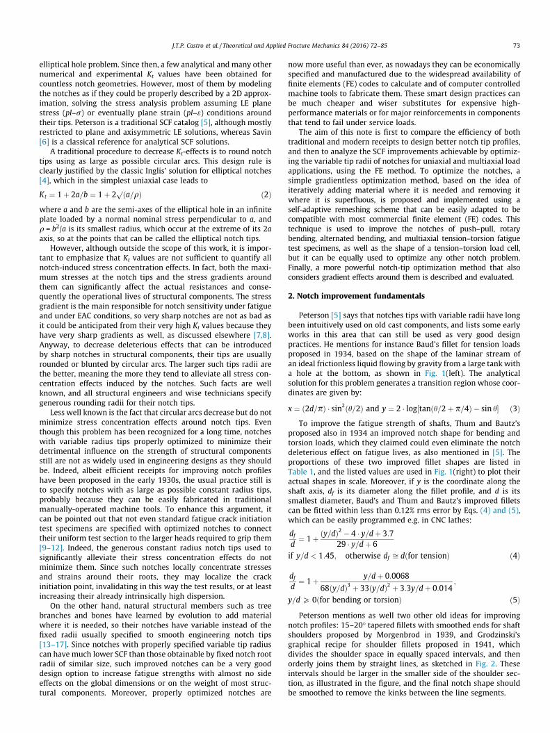
Peterson [5] says that notches tips with variable radii have longbeen intuitively used on old cast components, and lists some earlyworks in this area that can still be used as very good designpractices. He mentions for instance Baud’s fillet for tension loadsproposed in 1934, based on the shape of the laminar stream ofan ideal frictionless liquid flowing by gravity from a large tank witha hole at the bottom, as shown in Fig. 1(left). The analyticalsolution for this problem generates a transition region whose coor-dinates are given by:
x ¼ ð2d=pÞ � sin2ðh=2Þ and y ¼ 2 � log½tanðh=2þ p=4Þ � sin h� ð3ÞTo improve the fatigue strength of shafts, Thum and Bautz’s
proposed also in 1934 an improved notch shape for bending andtorsion loads, which they claimed could even eliminate the notchdeleterious effect on fatigue lives, as also mentioned in [5]. Theproportions of these two improved fillet shapes are listed inTable 1, and the listed values are used in Fig. 1(right) to plot theiractual shapes in scale. Moreover, if y is the coordinate along theshaft axis, df is its diameter along the fillet profile, and d is itssmallest diameter, Baud’s and Thum and Bautz’s improved filletscan be fitted within less than 0.12% rms error by Eqs. (4) and (5),which can be easily programmed e.g. in CNC lathes:
df
d¼ 1þ ðy=dÞ2 � 4 � y=dþ 3:7
29 � y=dþ 6if y=d < 1:45; otherwise df ffi dðfor tensionÞ ð4Þ
df
d¼ 1þ y=dþ 0:0068
68ðy=dÞ3 þ 33ðy=dÞ2 þ 3:3y=dþ 0:014;
y=d P 0ðfor bending or torsionÞ ð5ÞPeterson mentions as well two other old ideas for improving
notch profiles: 15–20� tapered fillets with smoothed ends for shaftshoulders proposed by Morgenbrod in 1939, and Grodzinski’sgraphical recipe for shoulder fillets proposed in 1941, whichdivides the shoulder space in equally spaced intervals, and thenorderly joins them by straight lines, as sketched in Fig. 2. Theseintervals should be larger in the smaller side of the shoulder sec-tion, as illustrated in the figure, and the final notch shape shouldbe smoothed to remove the kinks between the line segments.
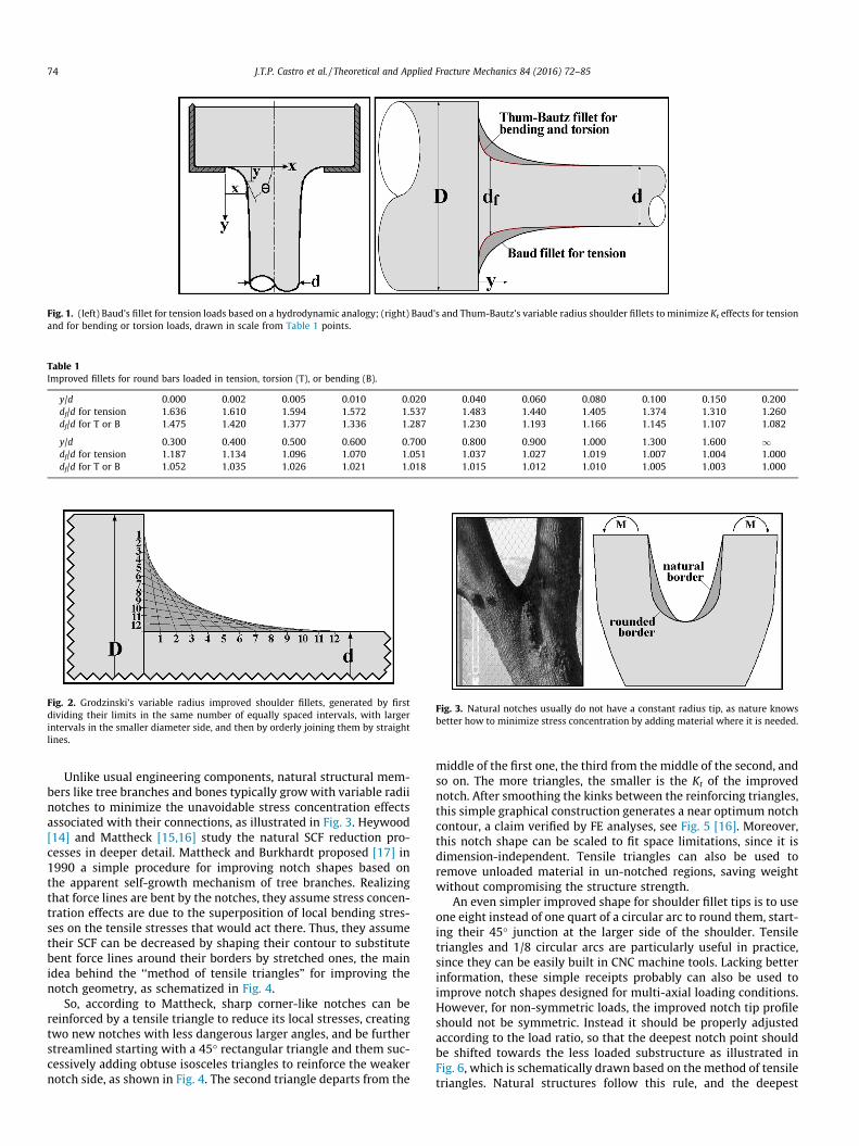
Fig. 3. Natural notches usually do not have a constant radius tip, as nature knowsbetter how to minimize stress concentration by adding material where it is needed.
Fig. 1. (left) Baud’s fillet for tension loads based on a hydrodynamic analogy; (right) Baud’s and Thum-Bautz’s variable radius shoulder fillets to minimize Kt effects for tensionand for bending or torsion loads, drawn in scale from Table 1 points.
Fig. 2. Grodzinski’s variable radius improved shoulder fillets, generated by firstdividing their limits in the same number of equally spaced intervals, with largerintervals in the smaller diameter side, and then by orderly joining them by straightlines.
Table 1Improved fillets for round bars loaded in tension, torsion (T), or bending (B).
y/d 0.000 0.002 0.005 0.010 0.020 0.040 0.060 0.080 0.100 0.150 0.200df/d for tension 1.636 1.610 1.594 1.572 1.537 1.483 1.440 1.405 1.374 1.310 1.260df/d for T or B 1.475 1.420 1.377 1.336 1.287 1.230 1.193 1.166 1.145 1.107 1.082
y/d 0.300 0.400 0.500 0.600 0.700 0.800 0.900 1.000 1.300 1.600 1df/d for tension 1.187 1.134 1.096 1.070 1.051 1.037 1.027 1.019 1.007 1.004 1.000df/d for T or B 1.052 1.035 1.026 1.021 1.018 1.015 1.012 1.010 1.005 1.003 1.000
74 J.T.P. Castro et al. / Theoretical and Applied Fracture Mechanics 84 (2016) 72–85
Unlike usual engineering components, natural structural mem-bers like tree branches and bones typically growwith variable radiinotches to minimize the unavoidable stress concentration effectsassociated with their connections, as illustrated in Fig. 3. Heywood[14] and Mattheck [15,16] study the natural SCF reduction pro-cesses in deeper detail. Mattheck and Burkhardt proposed [17] in1990 a simple procedure for improving notch shapes based onthe apparent self-growth mechanism of tree branches. Realizingthat force lines are bent by the notches, they assume stress concen-tration effects are due to the superposition of local bending stres-ses on the tensile stresses that would act there. Thus, they assumetheir SCF can be decreased by shaping their contour to substitutebent force lines around their borders by stretched ones, the mainidea behind the ‘‘method of tensile triangles” for improving thenotch geometry, as schematized in Fig. 4.
So, according to Mattheck, sharp corner-like notches can bereinforced by a tensile triangle to reduce its local stresses, creatingtwo new notches with less dangerous larger angles, and be furtherstreamlined starting with a 45� rectangular triangle and them suc-cessively adding obtuse isosceles triangles to reinforce the weakernotch side, as shown in Fig. 4. The second triangle departs from the
middle of the first one, the third from the middle of the second, andso on. The more triangles, the smaller is the Kt of the improvednotch. After smoothing the kinks between the reinforcing triangles,this simple graphical construction generates a near optimum notchcontour, a claim verified by FE analyses, see Fig. 5 [16]. Moreover,this notch shape can be scaled to fit space limitations, since it isdimension-independent. Tensile triangles can also be used toremove unloaded material in un-notched regions, saving weightwithout compromising the structure strength.
An even simpler improved shape for shoulder fillet tips is to useone eight instead of one quart of a circular arc to round them, start-ing their 45� junction at the larger side of the shoulder. Tensiletriangles and 1/8 circular arcs are particularly useful in practice,since they can be easily built in CNC machine tools. Lacking betterinformation, these simple receipts probably can also be used toimprove notch shapes designed for multi-axial loading conditions.However, for non-symmetric loads, the improved notch tip profileshould not be symmetric. Instead it should be properly adjustedaccording to the load ratio, so that the deepest notch point shouldbe shifted towards the less loaded substructure as illustrated inFig. 6, which is schematically drawn based on the method of tensiletriangles. Natural structures follow this rule, and the deepest
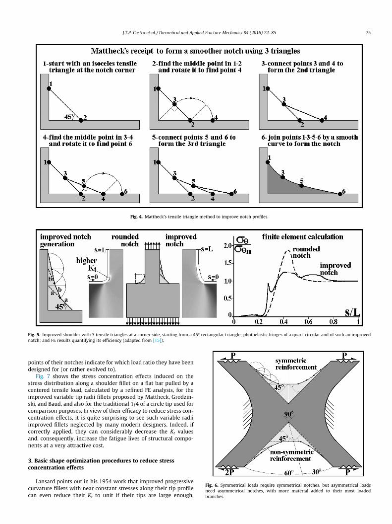
Fig. 4. Mattheck’s tensile triangle method to improve notch profiles.
Fig. 5. Improved shoulder with 3 tensile triangles at a corner side, starting from a 45� rectangular triangle; photoelastic fringes of a quart-circular and of such an improvednotch; and FE results quantifying its efficiency (adapted from [15]).
Fig. 6. Symmetrical loads require symmetrical notches, but asymmetrical loadsneed asymmetrical notches, with more material added to their most loadedbranches.
J.T.P. Castro et al. / Theoretical and Applied Fracture Mechanics 84 (2016) 72–85 75
points of their notches indicate for which load ratio they have beendesigned for (or rather evolved to).
Fig. 7 shows the stress concentration effects induced on thestress distribution along a shoulder fillet on a flat bar pulled by acentered tensile load, calculated by a refined FE analysis, for theimproved variable tip radii fillets proposed by Mattheck, Grodzin-ski, and Baud, and also for the traditional 1/4 of a circle tip used forcomparison purposes. In view of their efficacy to reduce stress con-centration effects, it is quite surprising to see such variable radiiimproved fillets neglected by many modern designers. Indeed, ifcorrectly applied, they can considerably decrease the Kt valuesand, consequently, increase the fatigue lives of structural compo-nents at a very attractive cost.
3. Basic shape optimization procedures to reduce stressconcentration effects
Lansard points out in his 1954 work that improved progressivecurvature fillets with near constant stresses along their tip profilecan even reduce their Kt to unit if their tips are large enough,
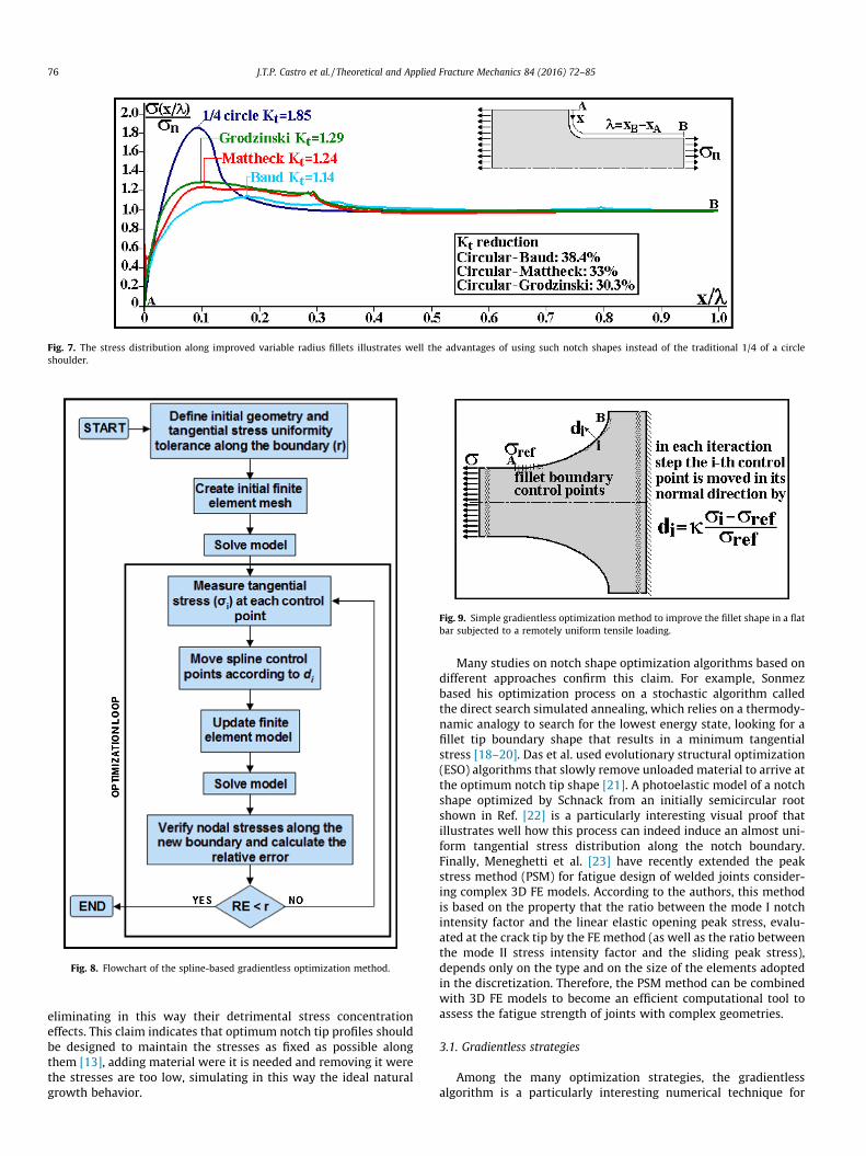
Fig. 7. The stress distribution along improved variable radius fillets illustrates well the advantages of using such notch shapes instead of the traditional 1/4 of a circleshoulder.
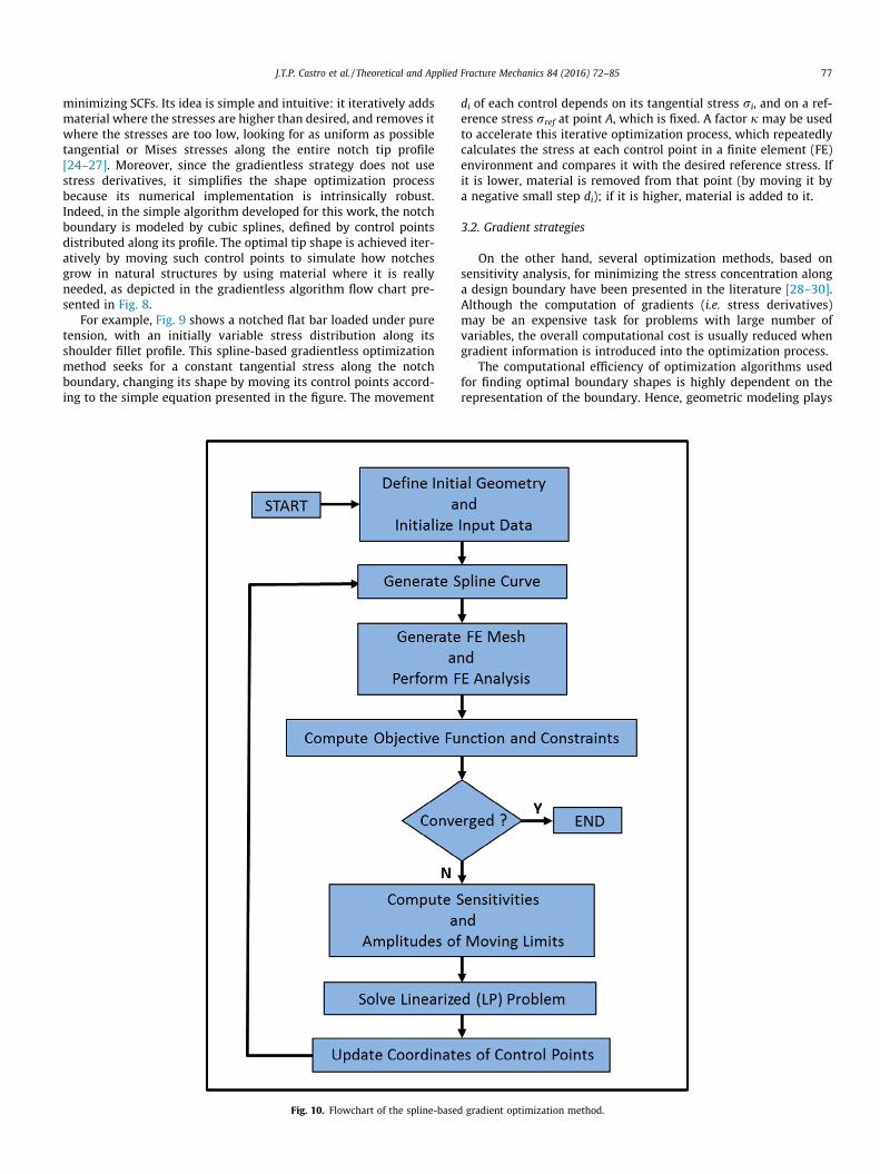
Fig. 8. Flowchart of the spline-based gradientless optimization method.
Fig. 9. Simple gradientless optimization method to improve the fillet shape in a flatbar subjected to a remotely uniform tensile loading.
76 J.T.P. Castro et al. / Theoretical and Applied Fracture Mechanics 84 (2016) 72–85
eliminating in this way their detrimental stress concentrationeffects. This claim indicates that optimum notch tip profiles shouldbe designed to maintain the stresses as fixed as possible alongthem [13], adding material were it is needed and removing it werethe stresses are too low, simulating in this way the ideal naturalgrowth behavior.
Many studies on notch shape optimization algorithms based ondifferent approaches confirm this claim. For example, Sonmezbased his optimization process on a stochastic algorithm calledthe direct search simulated annealing, which relies on a thermody-namic analogy to search for the lowest energy state, looking for afillet tip boundary shape that results in a minimum tangentialstress [18–20]. Das et al. used evolutionary structural optimization(ESO) algorithms that slowly remove unloaded material to arrive atthe optimum notch tip shape [21]. A photoelastic model of a notchshape optimized by Schnack from an initially semicircular rootshown in Ref. [22] is a particularly interesting visual proof thatillustrates well how this process can indeed induce an almost uni-form tangential stress distribution along the notch boundary.Finally, Meneghetti et al. [23] have recently extended the peakstress method (PSM) for fatigue design of welded joints consider-ing complex 3D FE models. According to the authors, this methodis based on the property that the ratio between the mode I notchintensity factor and the linear elastic opening peak stress, evalu-ated at the crack tip by the FE method (as well as the ratio betweenthe mode II stress intensity factor and the sliding peak stress),depends only on the type and on the size of the elements adoptedin the discretization. Therefore, the PSM method can be combinedwith 3D FE models to become an efficient computational tool toassess the fatigue strength of joints with complex geometries.
3.1. Gradientless strategies
Among the many optimization strategies, the gradientlessalgorithm is a particularly interesting numerical technique for
J.T.P. Castro et al. / Theoretical and Applied Fracture Mechanics 84 (2016) 72–85 77
minimizing SCFs. Its idea is simple and intuitive: it iteratively addsmaterial where the stresses are higher than desired, and removes itwhere the stresses are too low, looking for as uniform as possibletangential or Mises stresses along the entire notch tip profile[24–27]. Moreover, since the gradientless strategy does not usestress derivatives, it simplifies the shape optimization processbecause its numerical implementation is intrinsically robust.Indeed, in the simple algorithm developed for this work, the notchboundary is modeled by cubic splines, defined by control pointsdistributed along its profile. The optimal tip shape is achieved iter-atively by moving such control points to simulate how notchesgrow in natural structures by using material where it is reallyneeded, as depicted in the gradientless algorithm flow chart pre-sented in Fig. 8.
For example, Fig. 9 shows a notched flat bar loaded under puretension, with an initially variable stress distribution along itsshoulder fillet profile. This spline-based gradientless optimizationmethod seeks for a constant tangential stress along the notchboundary, changing its shape by moving its control points accord-ing to the simple equation presented in the figure. The movement
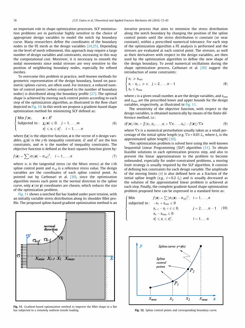
Fig. 10. Flowchart of the spline-base
di of each control depends on its tangential stress ri, and on a ref-erence stress rref at point A, which is fixed. A factor j may be usedto accelerate this iterative optimization process, which repeatedlycalculates the stress at each control point in a finite element (FE)environment and compares it with the desired reference stress. Ifit is lower, material is removed from that point (by moving it bya negative small step di); if it is higher, material is added to it.
3.2. Gradient strategies
On the other hand, several optimization methods, based onsensitivity analysis, for minimizing the stress concentration alonga design boundary have been presented in the literature [28–30].Although the computation of gradients (i.e. stress derivatives)may be an expensive task for problems with large number ofvariables, the overall computational cost is usually reduced whengradient information is introduced into the optimization process.
The computational efficiency of optimization algorithms usedfor finding optimal boundary shapes is highly dependent on therepresentation of the boundary. Hence, geometric modeling plays
d gradient optimization method.
78 J.T.P. Castro et al. / Theoretical and Applied Fracture Mechanics 84 (2016) 72–85
an important role in shape optimization processes. SCF minimiza-tion problems are in particular highly sensitive to the choice ofappropriate design variables to model the notch tip boundarycurve. Many researchers define the coordinates of the boundarynodes in the FE mesh as the design variables [24,25]. Dependingon the level of mesh refinement, this approach may require a largenumber of design variables and constraints, increasing in this waythe computational cost. Moreover, it is necessary to smooth thenodal movements since nodal stresses are very sensitive to theposition of neighboring boundary nodes, especially for refinedmeshes.
To overcome this problem in practice, well-known methods forgeometric representation of the design boundary, based on para-metric splines curves, are often used. For instance, a reduced num-ber of control points (when compared to the number of boundarynodes) is distributed along the boundary profile [27]. The optimalshape is achieved by moving such control points according to eachstep of the optimization algorithm, as illustrated in the flow chartdepicted in Fig. 10. In this work we propose a gradient-based shapeoptimization method for minimizing SCF defined as:
Min f ðxÞ; x 2 Rn
Subjected to : gjðxÞ 6 0; j ¼ 1; . . . ;m
xLi 6 xi 6 xUi ; i ¼ 1; . . . ;n
8><>:
ð6Þ
where f(x) is the objective function, x is the vector of n design vari-ables, gj(x) is the j-th inequality constraint, xiL and xi
U are the boxconstraints, and m is the number of inequality constraints. Theobjective function is defined as the least-squares function given by:
f ðxÞ ¼X
½riðxÞ � rref �2; i ¼ 1; . . . ;n ð7Þ
where ri is the tangential stress (or the Mises stress) at the i-thspline control point and rref is a reference stress value. The designvariables are the coordinates of each spline control point. Aspointed out by Carbonari et al. [30], since the optimizationalgorithm moves each point in the normal direction to the splinecurve, only x (or y) coordinates are chosen, which reduces the sizeof the optimization problem.
Fig. 11 shows a notched flat bar loaded under pure tension, withan initially variable stress distribution along its shoulder fillet pro-file. The proposed spline-based gradient optimization method is an
Fig. 11. Gradient-based optimization method to improve the fillet shape in a flatbar subjected to a remotely uniform tensile loading.
iterative process that aims to minimize the stress distributionalong the notch boundary by changing the position of the splinecontrol points until the stress distribution is constant (or nearconstant), within a prescribed numerical tolerance. For each stepof the optimization algorithm a FE analysis is performed and thestresses are evaluated at each control point. The stresses, as wellas their derivatives with respect to the design variables, are thenused by the optimization algorithm to define the new shape ofthe design boundary. To avoid numerical oscillations during theshape optimization process, Carbonari et al. [30] suggest theintroduction of some constraints:
x1 P xmin
xi � xj�1 P e; j ¼ 2; . . . ;n� 1xn 6 xmax
8><>:
ð8Þ
where e is a given small number, x are the design variables, and xmin
and xmax are the prescribed lower and upper bounds for the designvariables, respectively, as illustrated in Fig. 11.
The sensitivity of the objective function, with respect to thedesign variables, is obtained numerically by means of the finite dif-ference method, i.e.:
@f ðxÞ=@xi ¼ ½f ðx1; x2; . . . ; xi þrx; . . . ; xnÞ � f ðxÞ�=rx ð9Þwhere rx is a numerical perturbation usually taken as a small per-centage of the initial spline length (e.g. rx = 0.01 Ls, where Ls is theapproximated spline length) [30].
This optimization problem is solved here using the well-knownSequential Linear Programming (SLP) algorithm [31]. To obtainfeasible solutions in each optimization process step, and also toprevent the linear approximations to the problem to becomeunbounded, especially for under-constrained problems, a movinglimit strategy is usually required by the SLP algorithm. It consistsof defining box constraints for each design variable. The amplitudeof the moving limits (d) is also defined here as a fraction of theinitial spline length (e.g., d = 0.2 Ls) and is usually decreased asthe solution of the approximated linear problem is achieved ateach step. Finally, the complete gradient-based shape optimizationproblem proposed here can be expressed in a standard form as:
Min f ðxÞ ¼ P ½riðxÞ � rref �2; i ¼ 1; . . . ;nsubjected to : �x1 þ xmin 6 0
xj�1 � xj þ e 6 0; j ¼ 2; . . . ;n� 1xn � xmax 6 0xLi 6 xi 6 xUi ; i ¼ 1; . . .n
8>>>>>><>>>>>>:
ð10Þ
Fig. 12. Spline control points and corresponding boundary curve.
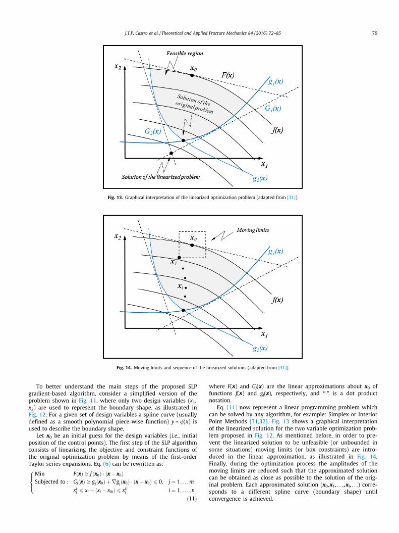
Fig. 13. Graphical interpretation of the linearized optimization problem (adapted from [31]).
Fig. 14. Moving limits and sequence of the linearized solutions (adapted from [31]).
J.T.P. Castro et al. / Theoretical and Applied Fracture Mechanics 84 (2016) 72–85 79
To better understand the main steps of the proposed SLPgradient-based algorithm, consider a simplified version of theproblem shown in Fig. 11, where only two design variables (x1,x2) are used to represent the boundary shape, as illustrated inFig. 12. For a given set of design variables a spline curve (usuallydefined as a smooth polynomial piece-wise function) y = /(x) isused to describe the boundary shape.
Let x0 be an initial guess for the design variables (i.e., initialposition of the control points). The first step of the SLP algorithmconsists of linearizing the objective and constraint functions ofthe original optimization problem by means of the first-orderTaylor series expansions. Eq. (6) can be rewritten as:
Min FðxÞ ffi f ðx0Þ � ðx� x0ÞSubjected to : GjðxÞ ffi gjðx0Þ þ rgjðx0Þ � ðx� x0Þ 6 0; j ¼ 1; . . .m
xLi 6 xi þ ðxi � x0iÞ 6 xUi i ¼ 1; . . . ;n
8><>:
ð11Þ
where F(x) and Gj(x) are the linear approximations about x0 offunctions f(x) and gj(x), respectively, and ‘‘�” is a dot productnotation.
Eq. (11) now represent a linear programming problem whichcan be solved by any algorithm, for example: Simplex or InteriorPoint Methods [31,32]. Fig. 13 shows a graphical interpretationof the linearized solution for the two variable optimization prob-lem proposed in Fig. 12. As mentioned before, in order to pre-vent the linearized solution to be unfeasible (or unbounded insome situations) moving limits (or box constraints) are intro-duced in the linear approximation, as illustrated in Fig. 14.Finally, during the optimization process the amplitudes of themoving limits are reduced such that the approximated solutioncan be obtained as close as possible to the solution of the orig-inal problem. Each approximated solution (x0,x1, . . . ,xi, . . .) corre-sponds to a different spline curve (boundary shape) untilconvergence is achieved.
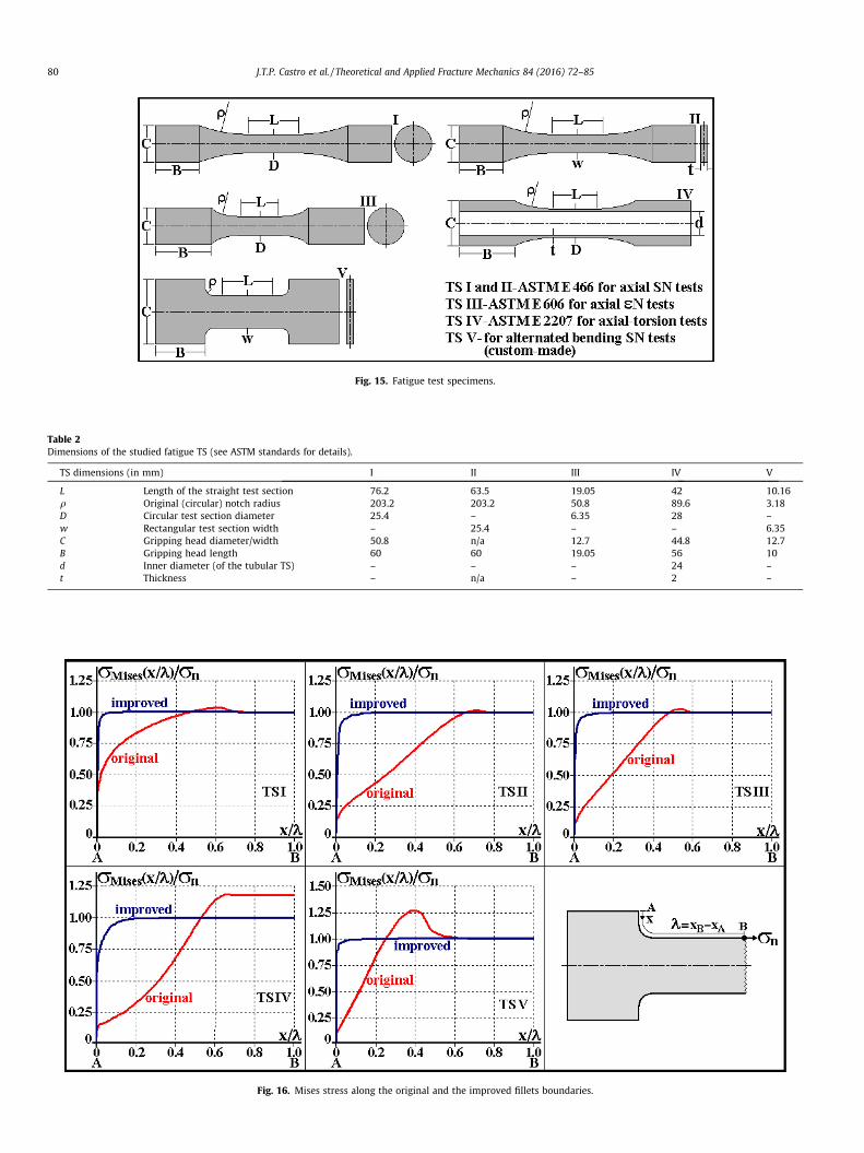
Fig. 15. Fatigue test specimens.
Table 2Dimensions of the studied fatigue TS (see ASTM standards for details).
TS dimensions (in mm) I II III IV V
L Length of the straight test section 76.2 63.5 19.05 42 10.16q Original (circular) notch radius 203.2 203.2 50.8 89.6 3.18D Circular test section diameter 25.4 – 6.35 28 –w Rectangular test section width – 25.4 – – 6.35C Gripping head diameter/width 50.8 n/a 12.7 44.8 12.7B Gripping head length 60 60 19.05 56 10d Inner diameter (of the tubular TS) – – – 24 –t Thickness – n/a – 2 –
Fig. 16. Mises stress along the original and the improved fillets boundaries.
80 J.T.P. Castro et al. / Theoretical and Applied Fracture Mechanics 84 (2016) 72–85
J.T.P. Castro et al. / Theoretical and Applied Fracture Mechanics 84 (2016) 72–85 81
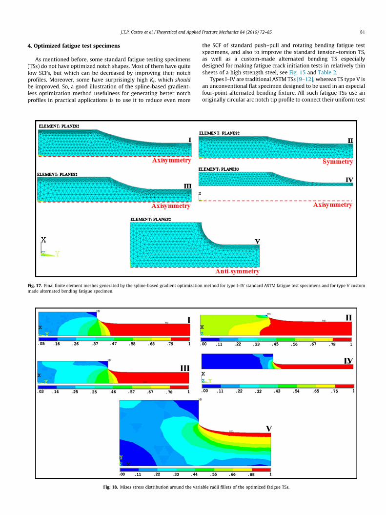
4. Optimized fatigue test specimens
As mentioned before, some standard fatigue testing specimens(TSs) do not have optimized notch shapes. Most of them have quitelow SCFs, but which can be decreased by improving their notchprofiles. Moreover, some have surprisingly high Kt, which shouldbe improved. So, a good illustration of the spline-based gradient-less optimization method usefulness for generating better notchprofiles in practical applications is to use it to reduce even more
Fig. 17. Final finite element meshes generated by the spline-based gradient optimizationmade alternated bending fatigue specimen.
Fig. 18. Mises stress distribution around the varia
the SCF of standard push–pull and rotating bending fatigue testspecimens, and also to improve the standard tension–torsion TS,as well as a custom-made alternated bending TS especiallydesigned for making fatigue crack initiation tests in relatively thinsheets of a high strength steel, see Fig. 15 and Table 2.
Types I–IV are traditional ASTM TSs [9–12], whereas TS type V isan unconventional flat specimen designed to be used in an especialfour-point alternated bending fixture. All such fatigue TSs use anoriginally circular arc notch tip profile to connect their uniform test
method for type I–IV standard ASTM fatigue test specimens and for type V custom
ble radii fillets of the optimized fatigue TSs.
82 J.T.P. Castro et al. / Theoretical and Applied Fracture Mechanics 84 (2016) 72–85
section to the larger heads needed to grip them, with generousradii that significantly decrease, but do not minimize their SCF.All such TSs were modeled in ANSYS APDL 12 assuming planestress conditions and using triangular FE with six nodes and twelvedegrees of freedom, but the schema depicted in Fig. 8 flow chartwould work in any other FE code. Due to their symmetry condi-tions, only one quarter of the TS need to be modeled. TS type Iand III are cylindrical and axisymmetric; type II has a rectangularsymmetric section; type IV has a tubular profile axisymmetricabout the y-axis; and type V has a rectangular profile anti-symmetric about the y-axis for its bending load conditions.
In particular, too many type V alternated-bending TSs with anoriginal rounded notch tips were initiating fatigue cracks at theirtip roots under actual test conditions, invalidating in this way
Fig. 19. Stress distribution along the bou
Fig. 20. Stress distribution along the boundary of the improved variable radii shou
Fig. 21. SCF and required length of original and im
those tests results, a quite annoying problem partially due to thehigh notch-sensitivity of the tested high-strength steel. But afterthe notch tip profile of those specimens was optimized, this prob-lem was completely eliminated and no other specimen broke nearthe notch root, a good illustration of how useful such procedurescan be in real life.
Fig. 16 shows the original and the improved Mises stress plotsalong the notch profiles of the various fatigue test specimens stud-ied here, calculated by FE models. Specimens type I–III already hadvery small SCF, but note how the original stress profile is variablealong their circular arc tips, whereas the variable notch radiiresulting from the gradient optimization process lead to a muchmore uniform stress distribution. On the other hand, specimentype IV, the standard shape for tension–torsion fatigue tests,
ndary of circular arc shoulder fillets.
lder fillets, for various initially quart-circular notch tips with 0.25 6 q/w 6 8.
proved TS type II with originally circular arc.
J.T.P. Castro et al. / Theoretical and Applied Fracture Mechanics 84 (2016) 72–85 83
originally had a surprisingly high Kt value, which was muchimproved by the optimization process. This improved shape isnow being successfully used in the multiaxial fatigue tests madeby our research group, see e.g. [33], so we can recommend it. Thisindicates that the ASTM tension–torsion standard should probablybe reviewed. Moreover, the crack localization problem observedwhen testing standard TS type V was solved by this process.
Fig. 17 shows the final FE meshes automatically generated bythis optimization process, and Fig. 18 shows the Mises stress distri-bution obtained along the entire optimized specimens (notice howuniform they turn out to be along the notch profile).
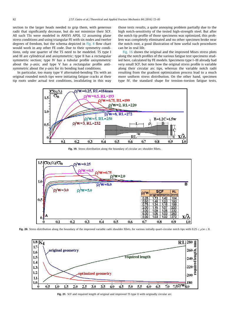
To better understand how a circular arc notch tip with a gener-ous rounding radius compares with an optimized variable radiiprofile for reducing the SCF of a given TS, Fig. 19 compares 7 differ-ent circular arc shoulder fillets, in order to show how the q/w ratioaffects the SCF of TS similar to the type II push–pull specimenshown in Fig. 15, but with a smaller C/w = 1.5 ratio. As shown inFig. 19, the SCF induced by a shoulder fillet with a relatively smallcircular arc with q/w = 0.25 reaches a SCF value Kt ffi 1.8. As the q/wratio increases, this Kt value reduces considerably, until it almostreaches a unit value when q/w ffi 8, which explains why ASTMspecified this ratio as its standard fillet radius.
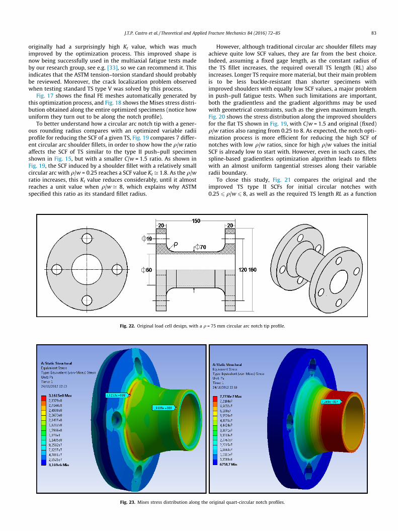
Fig. 22. Original load cell design, with a q
Fig. 23. Mises stress distribution along the
However, although traditional circular arc shoulder fillets mayachieve quite low SCF values, they are far from the best choice.Indeed, assuming a fixed gage length, as the constant radius ofthe TS fillet increases, the required overall TS length (RL) alsoincreases. Longer TS require more material, but their main problemis to be less buckle-resistant than shorter specimens withimproved shoulders with equally low SCF values, a major problemin push–pull fatigue tests. When such limitations are important,both the gradientless and the gradient algorithms may be usedwith geometrical constraints, such as the given maximum length.Fig. 20 shows the stress distribution along the improved shouldersfor the flat TS shown in Fig. 19, with C/w = 1.5 and original (fixed)q/w ratios also ranging from 0.25 to 8. As expected, the notch opti-mization process is more efficient for reducing the high SCF ofnotches with low q/w ratios, since for high q/w values the initialSCF is already low to start with. However, even in such cases, thespline-based gradientless optimization algorithm leads to filletswith an almost uniform tangential stresses along their variableradii boundary.
To close this study, Fig. 21 compares the original and theimproved TS type II SCFs for initial circular notches with0.25 6 q/w 6 8, as well as the required TS length RL as a function
= 75 mm circular arc notch tip profile.
original quart-circular notch profiles.

84 J.T.P. Castro et al. / Theoretical and Applied Fracture Mechanics 84 (2016) 72–85
of the q/w ratio of the original TS. These optimization proceduresmay be particularly efficient if applied to similarly notched struc-tural components when their q/w ratios are low due to space lim-itations, an important practical problem. In such cases, it may bemore interesting or even mandatory to find an economical and fea-sible improved geometry for the new notch profile respecting theoriginal space limitations, instead of searching for a globallyoptimum solution that would imply in a redesign of the entirecomponent. Indeed, Fig. 21 shows that it is possible to find animproved fillet profile that leads to both a reduced SCF and to asmaller length for a TS type II with originally circular arc shoulderfillets. For example, for an initial circular arc fillet with q/w = 1.5the SCF of the improved shoulder reduces from Kt ffi 1.22 toKt ffi 1.1 with a required TS length of RL ffi 215 mm, whereas acircular arc shoulder fillet would require q/wffi 2.6 and RLffi 228mmto achieve the same SCF value.
5. Optimization of the fillets of a tension–torsion load cell
Another practical application further illustrates the usefulnessof the proposed spline-based gradientless notch optimization pro-cess: the design of a compact tubular tension–torsion load cell
Fig. 24. Mises stress distribution along the improved load cell, with its notch
Fig. 25. Original and optimized fillets for
schematized in Fig. 22. This load cell was designed to work in acustom-made electromechanical multiaxial axial–torsional fatiguetesting machine under combined fatigue axial (push–pull) loadswith amplitudes up to P = 200 kN and torsion loads with ampli-tudes up to T = 1300 N m. The load cell had a fixed axial size andwas designed to measure the axial and the torsional loads usingconventional strain gages wired in separated Wheatstone bridges.Its original design used large circular arc shoulder fillets withq = 75 mm, but its FE analysis showed that although its torsionSCF was acceptable, KtT = 1.07, despite this large notch tip radiusits tension SCF was quite high, KtP = 1.61. The stress distributionsinduced by the axial and by the torsional loads along the originalnotch tip profile are illustrated in Fig. 23. The problem with thisoriginal design is that the too high axial SCF value was leading toa relatively short fatigue crack initiation life within its requiredreliability, a certainly not acceptable feature for the applicationin question.
So, the very same spline-based gradient shape optimizationprocedure described above was used to reduce the SCFs of thetubular tension–torsion load cell fillets, maintaining its overalllength. An axisymmetric model was created and the fillet profilewas iteratively changed, according to the proposed algorithm. After
profile optimized within the restriction of maintaining its overall length.
the tubular tension–torsion load cell.
J.T.P. Castro et al. / Theoretical and Applied Fracture Mechanics 84 (2016) 72–85 85
this shape iterative optimization process, the new fillet geometryreduced the tension SCF to KtP = 1.23 and the torsion one toKtT = 1.035, solving the fatigue life problem without significantlyincreasing the tension–torsion load cell weight or even its cost,since it had to be machined on a CNC lathe anyway, see Fig. 24.The original and the optimized fillets are schematized in Fig. 25.Note that the optimized profile in fact reduced the material usedin the fillet region, a non-intuitive result.
6. Conclusions
To maintain uniform tangential stress distributions along thenotch tip boundaries is the way to minimize their stress concentra-tion values, decreasing their deleterious effects that are especiallyprejudicial for fatigue applications. However, to obtain such uni-form stress profiles it is necessary to design the notches with avariable tip profile, instead of the circular arc used in most engi-neering structures to smooth their notch tips. Following this idea,iterative SCF gradientless and gradient-based optimization algo-rithms were developed and implemented in a finite element envi-ronment. The basic idea of this optimization technique is to usesplines to model any notch tip profile and iteratively change theposition of the spline control points until the stress distributionis constant (or near constant), according to a prescribed numericaltolerance. This is a very efficient way of significantly improving thenotch shapes by minimizing their SCF, a much useful featureespecially suitable to improve the intrinsic fatigue resistance ofstructural components that must be designed with large sectionreductions or with size limitations. To show how useful this simplebut powerful notch optimization algorithm can be in practice, itwas applied to propose better profiles for standard fatigue testspecimens, as well as to improve the design of a tension–torsionmultiaxial load cell that had a length limit, which despite its largenotch tip radii still was susceptible to fatigue failures, but it canequally be used with virtually any structural component.
Acknowledgments
CNPq, the Brazilian Research Council has provided researchscholarships for some of the authors, and ONR, the Office of NavalResearch of the US Navy has provided a grant under the supervi-sion of Dr. W. Nickerson to partially support this work.
References
[1] R.C.O. Góes, J.T.P. Castro, L.F. Martha, 3D effects around notch and crack tips,Int. J. Fatigue 62 (2014) 159–170.
[2] J.T.P. Castro, M.A. Meggiolaro, Fatigue Design Techniques, volumes 1 and 2,CreateSpace 2016.
[3] S. Timoshenko, J. Goodier, Theory of Elasticity, McGraw-Hill, 1969.[4] C.E. Inglis, Stress in a plate due to the presence of cracks and sharp corners,
Phil. Trans. R. Soc. A 215 (1913) 119–233.
[5] W. Pilkey, D. Pilkey, R. Peterson, Peterson’s Stress Concentration Factors, JohnWiley, 2008.
[6] G.N. Savin, Stress Distribution around Holes, NASA Technical Translation, 1968,p. 10.
[7] J.T.P. Castro, R.V. Landim, J.C.C. Leite, M.A. Meggiolaro, Prediction of notchsensitivity effects in fatigue and EAC, Fatigue Fract. Eng. Mater. Struct. 38 (2)(2015) 161–179.
[8] J.T.P. Castro, M.A. Meggiolaro, A.C.O. Miranda, H. Wu, A. Imad, B. Nouredine,Prediction of fatigue crack initiation lives at elongated notch roots using shortcrack concepts, Int. J. Fatigue 42 (2012) 172–182.
[9] ASTM E 606 – 92: Standard Practice for Strain-Controlled Fatigue Testing,Annual Book of ASTM Standards, ASTM 1993.
[10] ASTM E 2207 – 02: Standard Practice for Strain-Controlled Axial-TorsionalFatigue Testing with Thin-Walled Tubular Specimens, Annual Book of ASTMStandards, West Conshohocken, PA, 2002.
[11] ASTM E 606 – 92: Standard Practice for Controlled Constant Amplitude AxialFatigue Test of Metallic Materials, Annual Book of ASTM Standards, WestConshohocken, PA, 2002.
[12] M. Garrell, A. Shih, E.L. Curzio, R. Scattergood, Finite element analysis of stressconcentration in ASTM D 638 tension specimens, J. Testing Eval. 31 (1) (2003)52–57.
[13] R. Lansard, Fillets without stress concentration, Laboratories de la Société desAutomobiles Peugeot (1954).
[14] R.B. Heywood, Photoelasticity for Designers, Pergamon, 1969.[15] C. Mattheck, Design in Nature: Learning from Trees, Springer, 1998.[16] C. Mattheck, Teacher tree: the evolution of notch shape optimization from
complex to simple, Eng. Fract. Mech. 73 (12) (2006) 1732–1742.[17] C. Mattheck, S. Burkhardt, A new method of structural shape optimization
based on biological growth, Int. J. Fatigue 12 (3) (1990) 185–190.[18] F.O. Sonmez, Shape optimization of 2D structures using simulated annealing,
Comput. Methods Appl. Mech. Eng. (2007) 3279–3299.[19] F.O. Sonmez, Optimal shape design of shoulder fillets for flat and round bars
under various loadings, Proc. J. Mech. Eng. Sci. 223 (C8) (2009) 1741–1754.[20] F.O. Sonmez, Structural optimization using simulated annealing, in: Simulated
Annealing, I-Tech Education and Publishing, 2008.[21] R. Das, R. Jones, Y.M. Xie, Design of structures for optimal static strength using
ESO, Eng. Failure Anal. 12 (2005) 61–80.[22] E. Schnack, An optimization procedure for stress concentration by the finite
element technique, Int. J. Numer. Methods Eng. 14 (1979) 115–124.[23] G. Meneghetti, C. Guzzella, B. Atzori, The peak stress method combined with
3D finite element models for fatigue assessment of toe and root cracking insteel welded joints subjected to axial of bending loading, Fatigue Fract. Eng.Mater. Struct. 37 (2014) 722–739.
[24] M. Heller, R. Kaye, L.R.F. Rose, A gradientless finite element procedure forshape optimization, J. Strain Anal. 34 (5) (1999) 323–336.
[25] W.Waldman, M. Heller, G.X. Chen, Optimal free-form shapes for shoulder filletin flat plates under tension and bending, Int. J. Fatigue 23 (6) (2000) 509–523.
[26] Z. Wu, On the optimization problem of fillets and holes in plates withcurvatures constraints, Struct. Multidiscip. Opt. 35 (5) (2008) 499–506.
[27] Z. Wu, An efficient approach for shape optimization of components, Int. J.Mech. Sci. 47 (10) (2003) 1595–1610.
[28] P. Pedersen, C.L. Laursen, Design for minimum stress concentration by finiteelements and linear programming, J. Struct. Mech. 10 (1982–1983) 243–271.
[29] R. Kaye, M. Heller, Investigation of shape optimization for the design of lifeextension options for an F/A-18 airframe FS 470 bulkhead, J. Strain Anal. Eng.Des. 35 (6) (2000) 493–505.
[30] R.C. Carbonari, P.A. Muñoz-Rojas, E.Q. Andrade, G.H. Paulino, K. Nishimoto, E.C.N. Silva, Design of pressure vessels using shape optimization: an integratedapproach, Int. J. Press. Vessels Pip. 88 (2011) 198–212.
[31] G.N. Vanderplaats, Numerical Optimization Techniques for EngineeringDesign, McGraw-Hill, 1984.
[32] N. Karmarkar, A new polynomial-time algorithm for linear programming,Combinatorica 4 (4) (1984) 373–395.
[33] H. Wu, M.A. Meggiolaro, J.T.P. Castro, Validation of the multiaxial racetrackamplitude filter, Int. J. Fatigue (2016) (in press), http://dx.doi.org/10.1016/j.ijfatigue.2016.01.016.