then steel born - yyardim.com · 2016 then steel born ... higher installation costs and the ......
TRANSCRIPT

Fall sem. 2015-2016 5/9/2017
1
Str
uct
ure
De
sig
n I
I
-Fa
ll S
em
est
er
20
15
-20
16
Str
uct
ure
De
sig
n I
I
-Fa
ll S
em
est
er
20
15
-20
16
Then Steel Born
Assoc. Prof. Yavuz yardim
Some times in 17th Cost iron uses to construct one
bridge in Uk . Latter Wrought iron is used, this iron was
much more reliable for both tension, and compression,.
Wrought iron is an iron alloy with a very low carbon
(less than 0.08%) content in contrast to cast iron (2.1%
to 4%), and has fibrous inclusions known as slag up to
2% by weight.
The bridge is completed. It is opened as the
world's first iron bridge on New Year's Day 1781
Str
uct
ure
De
sig
n I
I
-Fa
ll S
em
est
er
20
15
-20
16
Str
uct
ure
De
sig
n I
I
-Fa
ll S
em
est
er
20
15
-20
16
Hope, we can go a steel factory in Oman
Assoc. Prof. Yavuz yardim

Fall se
m. 2
01
5-2
01
65
/9/2
01
72
Structure Design II - Fall Semester 2015-2016Structure Design II - Fall Semester 2015-2016
Asso
c. Pro
f. Yav
uz ya
rdim
Structure Design II - Fall Semester 2015-2016Structure Design II - Fall Semester 2015-2016
Asso
c. Pro
f. Yav
uz ya
rdim

Fall sem. 2015-2016 5/9/2017
3
Str
uct
ure
De
sig
n I
I
-Fa
ll S
em
est
er
20
15
-20
16
Str
uct
ure
De
sig
n I
I
-Fa
ll S
em
est
er
20
15
-20
16
Assoc. Prof. Yavuz yardim
Str
uct
ure
De
sig
n I
I
-Fa
ll S
em
est
er
20
15
-20
16
Str
uct
ure
De
sig
n I
I
-Fa
ll S
em
est
er
20
15
-20
16
Management and Control at Steel Construction Site
Assoc. Prof. Yavuz yardim
Erecting structural steelwork for building construction takes
place in a dynamic, changing environment where there are
many hazards and risks. Proper and timely planning and
coordination are the most effective ways to manage those
hazards and risks. Projects involving structural steel
construction have four main stages where risks to health
and safety need to be considered:
• design
• fabrication
• transport
• erection.

Fall se
m. 2
01
5-2
01
65
/9/2
01
74
Structure Design II - Fall Semester 2015-2016Structure Design II - Fall Semester 2015-2016
INT
RO
DU
CT
ION
TO
BS
59
50
Asso
c. Pro
f. Yav
uz ya
rdim
Structure Design II - Fall Semester 2015-2016Structure Design II - Fall Semester 2015-2016
Asso
c. Pro
f. Yav
uz ya
rdim

Fall sem. 2015-2016 5/9/2017
5
Str
uct
ure
De
sig
n I
I
-Fa
ll S
em
est
er
20
15
-20
16
Str
uct
ure
De
sig
n I
I
-Fa
ll S
em
est
er
20
15
-20
16
Aims of structural design Cl. 2.1.1.1
Assoc. Prof. Yavuz yardim
�The main aim of structural design is to design a safe
structure that will fulfill its intended purpose.
�The structure should be able to resist the predicted
loading for its entire design life with a sufficient margin of
safety.
� The in-service deflections and behaviour of the structure
must not be such that it is unacceptable for the intended
use.
�Other factors that should also be considered in the design
stage are economy, safety, erection, transport and
sustainability.
Str
uct
ure
De
sig
n I
I
-Fa
ll S
em
est
er
20
15
-20
16
Str
uct
ure
De
sig
n I
I
-Fa
ll S
em
est
er
20
15
-20
16
Limit states design
Assoc. Prof. Yavuz yardim
Factors are applied both to the loads and to the materials, to allow for the possibility
that the loads may be greater than the assumed values and that the materials may
be weaker than the assumed values. The design requirement is often expressed as:
F × γ l ≤ R / γm
where:
F is the load effect (e.g. force or
moment)
γ l is the load factor
R is the resistance or capacity of the
member
γm is the material factor

Fall sem. 2015-2016 5/9/2017
6
Str
uct
ure
De
sig
n I
I
-Fa
ll S
em
est
er
20
15
-20
16
Str
uct
ure
De
sig
n I
I
-Fa
ll S
em
est
er
20
15
-20
16
Limit states design
Assoc. Prof. Yavuz yardim
F × γ l ≤ R / γm
Using the partial factors in Table the design requirement can be
expressed more fully as:
Str
uct
ure
De
sig
n I
I
-Fa
ll S
em
est
er
20
15
-20
16
Str
uct
ure
De
sig
n I
I
-Fa
ll S
em
est
er
20
15
-20
16
Limit states design
Assoc. Prof. Yavuz yardim
In BS 5950 the γ factors have been combined to simplify the design.
The performance factor ( γ p ≈ 1.2) has been combined with the load
factors (γ Dead Load ≈ 1.15 and γ Imposed Load ≈ 1.3). The material
factors (γm1 and γm2) are combined into the recommended design
strengths.
Therefore, when designing to BS 5950, the relationship which
has to be satisfied is simply:
F × γ f ≤ R
where: γ f is the product of γ l and γ p and is
given in Table of the Standard.

Fall sem. 2015-2016 5/9/2017
7
Str
uct
ure
De
sig
n I
I
-Fa
ll S
em
est
er
20
15
-20
16
Str
uct
ure
De
sig
n I
I
-Fa
ll S
em
est
er
20
15
-20
16
Material strength variation
Assoc. Prof. Yavuz yardim
Str
uct
ure
De
sig
n I
I
-Fa
ll S
em
est
er
20
15
-20
16
Str
uct
ure
De
sig
n I
I
-Fa
ll S
em
est
er
20
15
-20
16
Assoc. Prof. Yavuz yardim
In practice, because the strength of steel is quoted by the
steel specifications as a “guaranteed minimum”, the curve
for steel strength is similar to that shown in Figure at
previous slide .
The mean strength of the steel is close to 310 N/mm2, but
the 95% confidence limit (i.e. mean minus 2 standard
deviations) is 275 N/mm2.
Material strength variation

Fall sem. 2015-2016 5/9/2017
8
Str
uct
ure
De
sig
n I
I
-Fa
ll S
em
est
er
20
15
-20
16
Str
uct
ure
De
sig
n I
I
-Fa
ll S
em
est
er
20
15
-20
16
Assoc. Prof. Yavuz yardim
Str
uct
ure
De
sig
n I
I
-Fa
ll S
em
est
er
20
15
-20
16
Str
uct
ure
De
sig
n I
I
-Fa
ll S
em
est
er
20
15
-20
16
Limit states
Assoc. Prof. Yavuz yardim
BS 5950-1 considers two classes of limit states. The ultimate limit
state (i.e. the point beyond which the structure would be unsafe) and
the serviceability limit state (i.e. the point beyond which the specified
service criteria are no longer met). The principal limit states covered
in BS 5950-1 are shown in Table .

Fall sem. 2015-2016 5/9/2017
9
Str
uct
ure
De
sig
n I
I
-Fa
ll S
em
est
er
20
15
-20
16
Str
uct
ure
De
sig
n I
I
-Fa
ll S
em
est
er
20
15
-20
16 Ultimate limit states
Assoc. Prof. Yavuz yardim
Application of load factorsWhen the structure reaches a limit state of strength or stability it is on the point
of being unsafe or about to collapse. It is necessary to verify that there is an
adequate factor of safety against this limiting condition.
In buildings not subject to loads from travelling cranes, the following load
combinations should be checked:
• Load combination 1: Dead load and imposed load (gravity loads)
plus notional horizontal forces
• Load combination 2: Dead load and wind load
• Load combination 3: Dead load, imposed load and wind load.
Str
uct
ure
De
sig
n I
I
-Fa
ll S
em
est
er
20
15
-20
16
Str
uct
ure
De
sig
n I
I
-Fa
ll S
em
est
er
20
15
-20
16
Assoc. Prof. Yavuz yardim
Partial factors for loads
Ultimate limit states
Fall sem. 2015-2016 5/9/2017
10
Str
uct
ure
De
sig
n I
I
-Fa
ll S
em
est
er
20
15
-20
16
Str
uct
ure
De
sig
n I
I
-Fa
ll S
em
est
er
20
15
-20
16
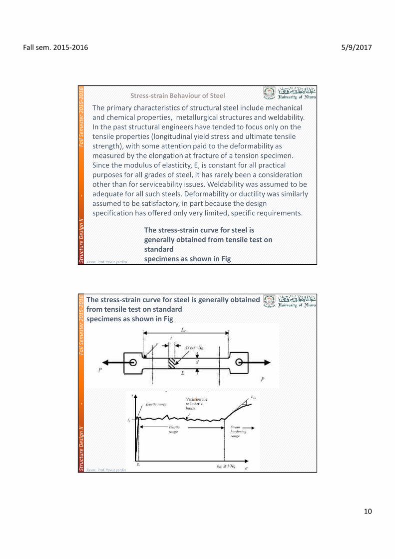
Stress-strain Behaviour of Steel
Assoc. Prof. Yavuz yardim
The primary characteristics of structural steel include mechanical
and chemical properties, metallurgical structures and weldability.
In the past structural engineers have tended to focus only on the
tensile properties (longitudinal yield stress and ultimate tensile
strength), with some attention paid to the deformability as
measured by the elongation at fracture of a tension specimen.
Since the modulus of elasticity, E, is constant for all practical
purposes for all grades of steel, it has rarely been a consideration
other than for serviceability issues. Weldability was assumed to be
adequate for all such steels. Deformability or ductility was similarly
assumed to be satisfactory, in part because the design
specification has offered only very limited, specific requirements.
The stress-strain curve for steel is
generally obtained from tensile test on
standard
specimens as shown in Fig
Str
uct
ure
De
sig
n I
I
-Fa
ll S
em
est
er
20
15
-20
16
Str
uct
ure
De
sig
n I
I
-Fa
ll S
em
est
er
20
15
-20
16
Assoc. Prof. Yavuz yardim
The stress-strain curve for steel is generally obtained
from tensile test on standard
specimens as shown in Fig

Fall se
m. 2
01
5-2
01
65
/9/2
01
7
11
Structure Design II - Fall Semester 2015-2016Structure Design II - Fall Semester 2015-2016
Asso
c. Pro
f. Yav
uz ya
rdim
Structure Design II - Fall Semester 2015-2016Structure Design II - Fall Semester 2015-2016
Asso
c. Pro
f. Yav
uz ya
rdim

Fall se
m. 2
01
5-2
01
65
/9/2
01
7
12
Structure Design II - Fall Semester 2015-2016Structure Design II - Fall Semester 2015-2016
Asso
c. Pro
f. Yav
uz ya
rdim
Structure Design II - Fall Semester 2015-2016Structure Design II - Fall Semester 2015-2016
Asso
c. Pro
f. Yav
uz ya
rdim

Fall se
m. 2
01
5-2
01
65
/9/2
01
7
13
Structure Design II - Fall Semester 2015-2016Structure Design II - Fall Semester 2015-2016
Asso
c. Pro
f. Yav
uz ya
rdim
Structure Design II - Fall Semester 2015-2016Structure Design II - Fall Semester 2015-2016
Pro
po
sed
Stru
ctura
l Sy
stem
fir Ste
el B
uild
ing
s

Fall se
m. 2
01
5-2
01
65
/9/2
01
7
14
Structure Design II - Fall Semester 2015-2016Structure Design II - Fall Semester 2015-2016
Asso
c. Pro
f. Yav
uz ya
rdim
Structure Design II - Fall Semester 2015-2016Structure Design II - Fall Semester 2015-2016
Asso
c. Pro
f. Yav
uz ya
rdim
Fall se
m. 2
01
5-2
01
65
/9/2
01
7
15
Structure Design II - Fall Semester 2015-2016Structure Design II - Fall Semester 2015-2016
Asso
c. Pro
f. Yav
uz ya
rdim
Structure Design II - Fall Semester 2015-2016Structure Design II - Fall Semester 2015-2016
Asso
c. Pro
f. Yav
uz ya
rdim
Fall sem. 2015-2016 5/9/2017
16
Str
uct
ure
De
sig
n I
I
-Fa
ll S
em
est
er
20
15
-20
16
Str
uct
ure
De
sig
n I
I
-Fa
ll S
em
est
er
20
15
-20
16
Assoc. Prof. Yavuz yardim
Str
uct
ure
De
sig
n I
I
-Fa
ll S
em
est
er
20
15
-20
16
Str
uct
ure
De
sig
n I
I
-Fa
ll S
em
est
er
20
15
-20
16
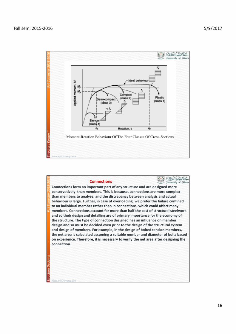
Connections
Assoc. Prof. Yavuz yardim
Connections form an important part of any structure and are designed more
conservatively than members. This is because, connections are more complex
than members to analyse, and the discrepancy between analysis and actual
behaviour is large. Further, in case of overloading, we prefer the failure confined
to an individual member rather than in connections, which could affect many
members. Connections account for more than half the cost of structural steelwork
and so their design and detailing are of primary importance for the economy of
the structure. The type of connection designed has an influence on member
design and so must be decided even prior to the design of the structural system
and design of members. For example, in the design of bolted tension members,
the net area is calculated assuming a suitable number and diameter of bolts based
on experience. Therefore, it is necessary to verify the net area after designing the
connection.

Fall sem. 2015-2016 5/9/2017
17
Str
uct
ure
De
sig
n I
I
-Fa
ll S
em
est
er
20
15
-20
16
Str
uct
ure
De
sig
n I
I
-Fa
ll S
em
est
er
20
15
-20
16
Assoc. Prof. Yavuz yardim
The connections provided in steel structures can be classified as 1)
riveted 2) bolted and 3) welded connections.
Riveted connections were once very popular and are still used in
some
cases but will gradually be replaced by bolted connections. This is
due to the low strength of rivets, higher installation costs and the
inherent inefficiency of the connection. Welded connections have
the advantage that no holes need to be drilled in the member and
consequently have higher efficiencies. However, welding in the field
may be difficult, costly, and time consuming. Welded connections
are also susceptible to failure by cracking under repeated cyclic
loads due to fatigue which may be due to working loads such as
trains passing
over a bridge (high-cycle fatigue) or earthquakes (low-cycle fatigue).
A special type of bolted connection using High Strength Friction
Grip (HSFG)
Str
uct
ure
De
sig
n I
I
-Fa
ll S
em
est
er
20
15
-20
16
Str
uct
ure
De
sig
n I
I
-Fa
ll S
em
est
er
20
15
-20
16
Bolt Connection
Assoc. Prof. Yavuz yardim

Fall sem. 2015-2016 5/9/2017
18
Str
uct
ure
De
sig
n I
I
-Fa
ll S
em
est
er
20
15
-20
16
Str
uct
ure
De
sig
n I
I
-Fa
ll S
em
est
er
20
15
-20
16
Assoc. Prof. Yavuz yardim
bolts has been found to perform better under such conditions than
the conventional black bolts used to resist predominantly static
loading. Bolted connections are also easy to inspect and replace. The
choice of using a particular type of connection is entirely that of the
designer and he should take his decision based on a good
understanding of the connection behaviour, economy and speed of
construction.
Type of bolt connections
Str
uct
ure
De
sig
n I
I
-Fa
ll S
em
est
er
20
15
-20
16
Str
uct
ure
De
sig
n I
I
-Fa
ll S
em
est
er
20
15
-20
16
Assoc. Prof. Yavuz yardim

Fall se
m. 2
01
5-2
01
65
/9/2
01
7
19
Structure Design II - Fall Semester 2015-2016Structure Design II - Fall Semester 2015-2016
Asso
c. Pro
f. Yav
uz ya
rdim
Structure Design II - Fall Semester 2015-2016Structure Design II - Fall Semester 2015-2016
Asso
c. Pro
f. Yav
uz ya
rdim

Fall se
m. 2
01
5-2
01
65
/9/2
01
7
20
Structure Design II - Fall Semester 2015-2016Structure Design II - Fall Semester 2015-2016
Asso
c. Pro
f. Yav
uz ya
rdim
Structure Design II - Fall Semester 2015-2016Structure Design II - Fall Semester 2015-2016
Asso
c. Pro
f. Yav
uz ya
rdim

Fall sem. 2015-2016 5/9/2017
21
Str
uct
ure
De
sig
n I
I
-Fa
ll S
em
est
er
20
15
-20
16
Str
uct
ure
De
sig
n I
I
-Fa
ll S
em
est
er
20
15
-20
16
Assoc. Prof. Yavuz yardim
Str
uct
ure
De
sig
n I
I
-Fa
ll S
em
est
er
20
15
-20
16
Str
uct
ure
De
sig
n I
I
-Fa
ll S
em
est
er
20
15
-20
16
Assoc. Prof. Yavuz yardim
Bolt HolesSince HSFG bolts under working loads, do not rely on resistance
from bearing, holes larger than usual can be provided to ease
erection and take care of lack-of-fit. Typical hole types that can be
used are standard, extra large and short or long slotted. These are
shown in Fig.

Fall sem. 2015-2016 5/9/2017
22
Str
uct
ure
De
sig
n I
I
-Fa
ll S
em
est
er
20
15
-20
16
Str
uct
ure
De
sig
n I
I
-Fa
ll S
em
est
er
20
15
-20
16
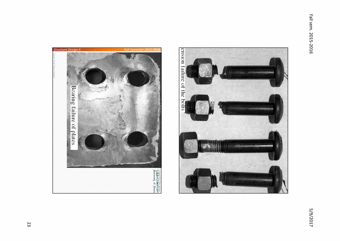
The possible limit states or failure modes that may
control the strength of a bolted connection is shown in
Figure
Assoc. Prof. Yavuz yardim
Shear failure of bolt
Shear failure of plate
Bearing failure of bolt
Bearing failure of plate
Tensile failure of bolts
Bending of bolts
Tensile failure of plate
Str
uct
ure
De
sig
n I
I
-Fa
ll S
em
est
er
20
15
-20
16
Str
uct
ure
De
sig
n I
I
-Fa
ll S
em
est
er
20
15
-20
16
Assoc. Prof. Yavuz yardim
Fall se
m. 2
01
5-2
01
65
/9/2
01
7
23
Structure Design II - Fall Semester 2015-2016Structure Design II - Fall Semester 2015-2016
Asso
c. Pro
f. Yav
uz ya
rdim
Structure Design II - Fall Semester 2015-2016Structure Design II - Fall Semester 2015-2016
Asso
c. Pro
f. Yav
uz ya
rdim

Fall sem. 2015-2016 5/9/2017
24
Str
uct
ure
De
sig
n I
I
-Fa
ll S
em
est
er
20
15
-20
16
Str
uct
ure
De
sig
n I
I
-Fa
ll S
em
est
er
20
15
-20
16
Assoc. Prof. Yavuz yardim
Str
uct
ure
De
sig
n I
I
-Fa
ll S
em
est
er
20
15
-20
16
Str
uct
ure
De
sig
n I
I
-Fa
ll S
em
est
er
20
15
-20
16
Connection
Assoc. Prof. Yavuz yardim
Arc Welding Processes
Shielded Metal Arc Welding (SMAW)
In Shielded Metal Arc Welding or SMAW , heating is done by means of electric arc between
a coated electrode and the material being joined. In case bare wire electrode (without
coating) is employed, the molten metal gets exposed to atmosphere and combines
chemically with oxygen and nitrogen forming defective welds. The electrode coating on the
welding rod forms a gaseous shield that helps to exclude oxygen and stabilise the arc.
Submerged Arc Welding (SAW)
Shielded Metal Arc Welding (SMAW)

Fall sem. 2015-2016 5/9/2017
25
Str
uct
ure
De
sig
n I
I
-Fa
ll S
em
est
er
20
15
-20
16
Str
uct
ure
De
sig
n I
I
-Fa
ll S
em
est
er
20
15
-20
16
Assoc. Prof. Yavuz yardim
Submerged Arc Welding (SAW)
In this arc welding process, the arc is not visible because it is covered
by a blanket of fusible powdered flux. The bare metal electrode is
deposited as a joining material. The flux, which is a special feature of
the method, protects the weld pool against the atmosphere. The arc
once started is at all times covered by the flux