quality plan for installation - jantermanter.com · installation power house structural steel works...
TRANSCRIPT
QUALITY PLAN FOR INSTALLATION
POWER HOUSE STRUCTURAL STEEL WORKS (ERECTION)
MEJIA TPS EXTN. ( UNIT 5 & 6)
2 x 250 MW
BHARAT HEAVY ELECTRICALS LIMITED WER SECTOR EASTERN REGION
DOC. NO. QPE-CL-04-52 REV. NO. R00
FMT-QP-001 REV.01
PO
QUALITY PLAN FOR
INSTALLATION
POWER HOUSE STRUCTURAL STEEL WORKS (ERECTION)
MEJIA TPS EXTN. (UNITS 5 & 6 ) ( 2 x 250 MW )
PREPARED BY
SR MANAGER/QLY, PSER
APPROVED BY HEAD / QLY, PSER
DOCUMENT NO. QPE - CL – 04-52
ORIGINAL DATE OF ISSUE 20.08.2004 REVISION NO. & DATE R00 / 20.08.2004 COPY NO.
ISSUED TO
DATE OF ISSUE
CONTROLLED / INFORMATION COPY
ISSUED BY (SIGNATURE & DESIGNATION)
BHARAT HEAVY ELECTRICALS LIMITED POWER SECTOR EASTERN REGION
DOC. NO. : QPE-CL-04-52 REV. NO. : R00
PSER
CONTENTS
SHEET 1 / 1 SHEETS S.NO.
DESCRIPTION
NO. OF SHEETS
1.
STATUS OF AMENDMENTS
1
2.
AUTHORISATION FOR DIFFERENT CATEGORIES OF CHECK
1
3.
STATEMENT OF CHECKS FOR ERECTION i) Raw Materials ii) Marking and Cutting iii) Forming iv) Fit up v) Pre-heating vi) Welding vii) Non destructive Testing viii) Clearing and Painting ix) Foundation Checks x) Roof truss Pre-assembly & Erection xi) Welding & NDE
14
4.
Annexure ( I & II)
4
5.
Table A1 to A6
8
6.
WPS
2
7.
Documents referred in Quality Plan
1
8.
LOGSHEET L-00 TO L-12
16
FMT-QP-003 REV.00
DOC. NO. : QPE-CL-04-52 REV. NO. : R00
PSER
STATUS OF AMENDMENTS
SHEET 1 / 1 SHEETS SL. NO.
REFERENCE OF SHEETS AMENDED
AMENDMENT NO. & DATE
REMARKS
-NIL -
FMT-QP-016 REV.00
PSER
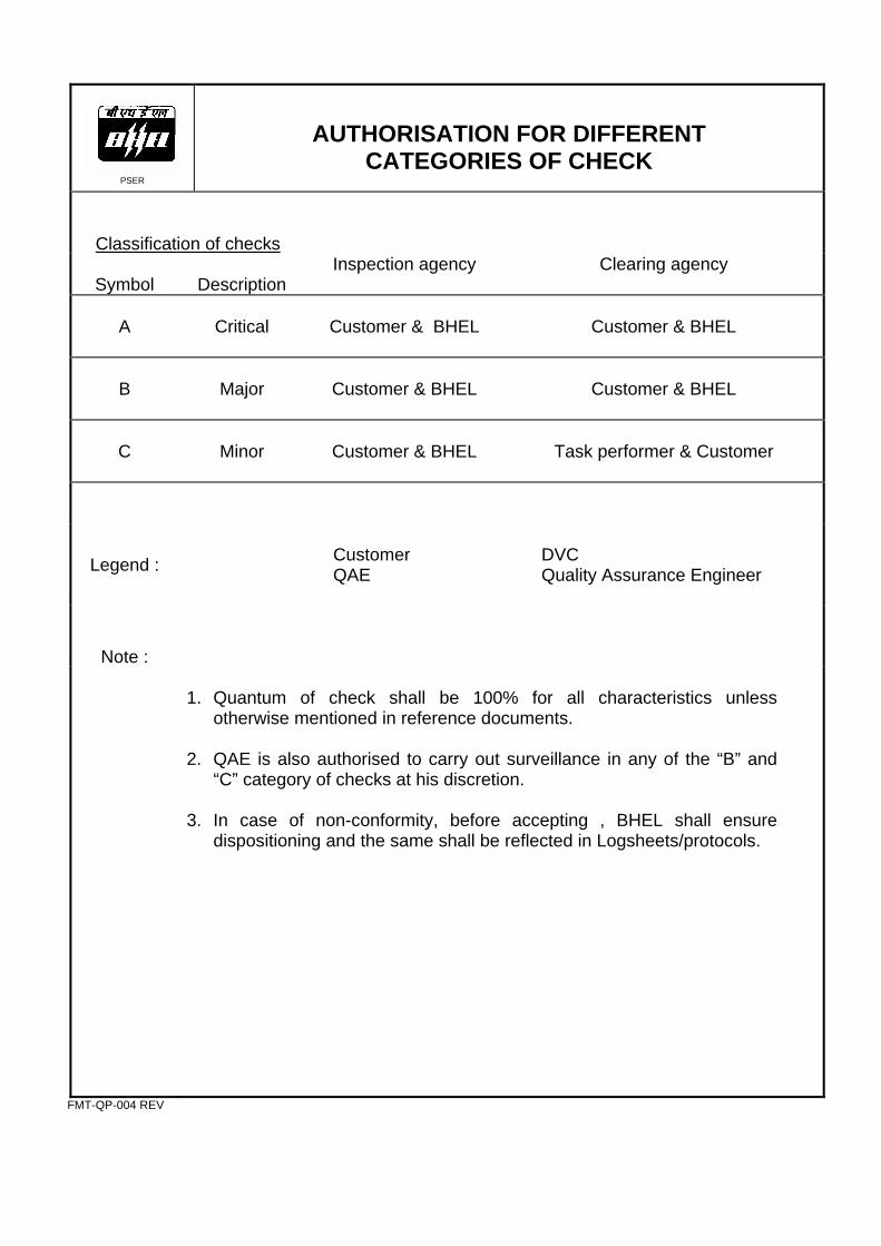
AUTHORISATION FOR DIFFERENT CATEGORIES OF CHECK
Classification of checks
Symbol
Description
Inspection agency Clearing agency
A
Critical
Customer & BHEL
Customer & BHEL
B
Major
Customer & BHEL
Customer & BHEL
C
Minor
Customer & BHEL
Task performer & Customer
Legend :
Customer QAE
DVC Quality Assurance Engineer
Note :
1. Quantum of check shall be 100% for all characteristics unless
otherwise mentioned in reference documents. 2. QAE is also authorised to carry out surveillance in any of the “B” and
“C” category of checks at his discretion. 3. In case of non-conformity, before accepting , BHEL shall ensure
dispositioning and the same shall be reflected in Logsheets/protocols.
FMT-QP-004 REV
PSER
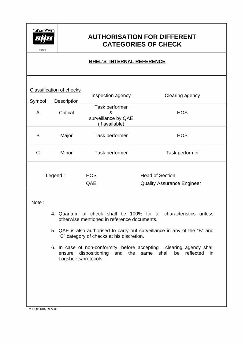
AUTHORISATION FOR DIFFERENT CATEGORIES OF CHECK
BHEL'S INTERNAL REFERENCE
Classification of checks
Symbol
Description
Inspection agency Clearing agency
A
Critical
Task performer &
surveillance by QAE (if available)
HOS
B
Major
Task performer
HOS
C
Minor
Task performer
Task performer
Legend :
HOS
Head of Section
QAE Quality Assurance Engineer
Note :
4. Quantum of check shall be 100% for all characteristics unless
otherwise mentioned in reference documents. 5. QAE is also authorised to carry out surveillance in any of the “B” and
“C” category of checks at his discretion. 6. In case of non-conformity, before accepting , clearing agency shall
ensure dispositioning and the same shall be reflected in Logsheets/protocols.
FMT-QP-004 REV.01
DOC. NO. : QPE-CL-04-52 REV. NO. : R00
PSER
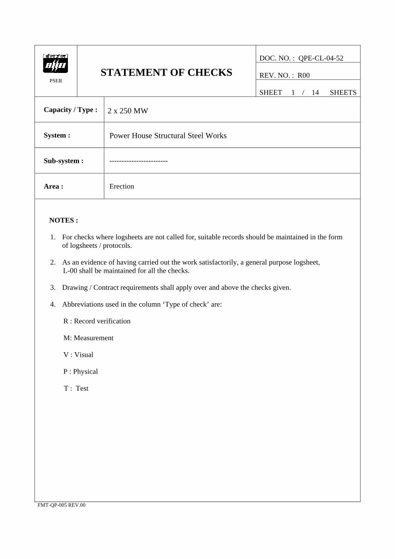
STATEMENT OF CHECKS
SHEET 1 / 14 SHEETS
Capacity / Type :
2 x 250 MW
System :
Power House Structural Steel Works
Sub-system :
------------------------
Area :
Erection
NOTES :
1. For checks where logsheets are not called for, suitable records should be maintained in the form of logsheets / protocols.
2. As an evidence of having carried out the work satisfactorily, a general purpose logsheet, L-00 shall be maintained for all the checks. 3. Drawing / Contract requirements shall apply over and above the checks given.
4. Abbreviations used in the column ‘Type of check’ are:
R : Record verification M: Measurement V : Visual P : Physical
T : Test FMT-QP-005 REV.00
DOC. NO. QPE-CL-04-52
PSER
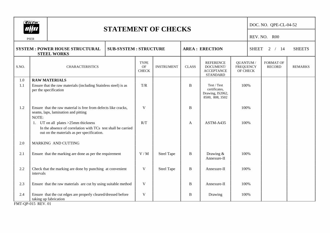
STATEMENT OF CHECKS REV. NO. R00
SYSTEM : POWER HOUSE STRUCTURAL STEEL WORKS
SUB-SYSTEM : STRUCTURE
AREA : ERECTION
SHEET 2 / 14 SHEETS
S.NO.
CHARACTERISTICS
TYPE
OF CHECK
INSTRUMENT
CLASS
REFERENCE DOCUMENT/
ACCEPTANCE STANDARD
QUANTUM / FREQUENCY
OF CHECK
FORMAT OF
RECORD
REMARKS
1.0 RAW MATERIALS 1.1 Ensure that the raw materials (including Stainless steel) is as
per the specification T/R B Test / Test
certificates, Drawing, IS2062, 8500, 808, 3502
100%
1.2 Ensure that the raw material is free from defects like cracks,
seams, laps, lamination and pitting V B 100%
NOTE: 1. UT on all plates >25mm thickness
In the absence of correlation with TCs test shall be carried out on the materials as per specification.
R/T A ASTM-A435 100%
2.0 MARKING AND CUTTING
2.1 Ensure that the marking are done as per the requirement V / M Steel Tape B Drawing &
Annexure-II 100%
2.2 Check that the marking are done by punching at convenient
intervals V Steel Tape B Annexure-II 100%
2.3 Ensure that the raw materials are cut by using suitable method V B Annexure-II 100%
2.4 Ensure that the cut edges are properly cleared/dressed before
taking up fabrication V B Drawing 100%
FMT-QP-015 REV. 01

DOC. NO. QPE-CL-04-52
PSER
STATEMENT OF CHECKS REV. NO. R00
SYSTEM : POWER HOUSE STRUCTURAL STEEL WORKS
SUB-SYSTEM : STRUCTURE
AREA : ERECTION
SHEET 3 / 14 SHEETS
S.NO.
CHARACTERISTICS
TYPE
OF CHECK
INSTRUMENT
CLASS
REFERENCE DOCUMENT/
ACCEPTANCE STANDARD
QUANTUM / FREQUENCY
OF CHECK
FORMAT OF
RECORD
REMARKS
2.5 Check that the raw materials after cutting are identified with
part number. V B Drawing 100%
3.0 FORMING (If applicable)
3.1 Ensure that forming is done using proper tooling free from
damages. V C Drawing 100%
4.0 FIT UP:
4.1 Ensure proper fit up before welding M Measuring Tape B Drawing 100% Protocol
4.2 Check that the gap is minimum for all fillet welds ( max. gap
2 mm ) M Measuring Tape B Drawing 100% Protocol
4.3 Ensure that the butt weld joints are properly aligned and the
offset is not to exceed 10% of the thickness of the thinner part of the joint. Maximum permitted value is 3.2 mm.
M Measuring Tape B Drawing 100% Protocol
4.4 Ensure match markings are punched for all trial assembled
components. M Measuring Tape B Drawing 100% Protocol
FMT-QP-015 REV. 01

DOC. NO. QPE-CL-04-52
PSER
STATEMENT OF CHECKS REV. NO. R00
SYSTEM : POWER HOUSE STRUCTURAL STEEL WORKS
SUB-SYSTEM : STRUCTURE
AREA : ERECTION
SHEET 4 / 14 SHEETS
S.NO.
CHARACTERISTICS
TYPE
OF CHECK
INSTRUMENT
CLASS
REFERENCE DOCUMENT/
ACCEPTANCE STANDARD
QUANTUM / FREQUENCY
OF CHECK
FORMAT OF
RECORD
REMARKS
5.0 PREHEATING:
5.1 Ensure pre heating is carried out wherever applicable. (using appropriate method)
V Thermal chalk B Annexure-II 100% Protocol
5.2 Ensure that the preheating temperature is uniform prior to
start of welding as well as during the welding. V Thermal chalk B Annexure-II 100% Site Log
6.0 WELDING:
6.1 Ensure that the qualified welders and qualified welding
procedures are used for all welding. T/R A Welding
Manual, WPS, IS817 & ASME
SEC. IX
100% Site Log
6.2 Ensure that the welding consumables are as per WPS. R A Welding
Manual, WPS, IS817 & ASME
SEC. IX
100% Site Log
6.3 Ensure proper edge preparation wherever required. V Bevel protractor B Drawing 100% Site Log
6.4 Ensure proper sequence of welding. V B WPS 100%
6.5 Check that the temporary attachment welded are removed
and ground & painted V B 100%
FMT-QP-015 REV. 01

DOC. NO. QPE-CL-04-52
PSER
STATEMENT OF CHECKS REV. NO. R00
SYSTEM : POWER HOUSE STRUCTURAL STEEL WORKS
SUB-SYSTEM : STRUCTURE
AREA : ERECTION
SHEET 5 / 14 SHEETS
S.NO.
CHARACTERISTICS
TYPE
OF CHECK
INSTRUMENT
CLASS
REFERENCE DOCUMENT/
ACCEPTANCE STANDARD
QUANTUM / FREQUENCY
OF CHECK
FORMAT OF
RECORD
REMARKS
6.6 Check and ensure that the overlap/excess weld metal is removed by grinding and painted.
V B 100%
6.7 Check the measurement of parts after welding for the
correctness of dimension & matching. M Measuring Tape B Drawing 100% Protocol
7.0 NON DESTRUCTIVE TESTING:
7.1 Carry out RT/UT/LPI as applicable T Testing
equipment A Drawing ,
Annexure-I & NDE Manual
As per Annexure-I
protocol
8.0 CLEANING AND PAINTING:
8.1 Ensure that the surface are cleaned and painted as specified V B Specification 100%
8.2 Ensure that the following markings are done
a)Assemblies designation V C Drawing 100% b)Part Number V C Drawing 100% c)Any other important identifications V C Drawing 100%
8.3 Ensure Dry Film Thickness of paint is as per specification M B Specification 100% Note : All tolerances during fabrication should be as per
Annexure-II
FMT-QP-015 REV. 01

DOC. NO. QPE-CL-04-52
PSER
STATEMENT OF CHECKS REV. NO. R00
SYSTEM : POWER HOUSE STRUCTURAL STEEL WORKS
SUB-SYSTEM : STRUCTURE
AREA : ERECTION
SHEET 6 / 14 SHEETS
S.NO.
CHARACTERISTICS
TYPE
OF CHECK
INSTRUMENT
CLASS
REFERENCE DOCUMENT/
ACCEPTANCE STANDARD
QUANTUM / FREQUENCY
OF CHECK
FORMAT OF
RECORD
REMARKS
9.0 FOUNDATION CHECKS:
9.1 Ensure availability of permanent Bench Mark. V B 100%
9.2 Check the foundations are cast as per requirement and with
proper positioning of foundation bolts/ inserts as per drg. M Measuring Tape B Drawing 100% L-01
9.3 Check the orientation of the foundation. V C Drawing 100%
9.4 Check the top level of foundation pedestals with respect to
permanent benchmark. M Dumpy Level B Drawing &
Annexure-I 100% L-02
9.5 Check the centre to centre distance of column foundation
pedestals with respect to the reference axis. M Measuring Tape/
Theodolite B Drawing &
Annexure-I 100% L-03
9.6 Check the diagonals between column foundation pedestals. M Measuring Tape B Drawing &
Annexure-I 100% L-04
9.7 Check the pitch distance of foundation bolts on both axis and
diagonals. M Measuring Tape B Drawing &
Annexure-I 100% L-05
10.0 COLUMN PRE-ASSEMBLY CHECKS:
10.1 Ensure cleaning of Base plate and HSFG bolt area V C 100%
FMT-QP-015 REV. 01

DOC. NO. QPE-CL-04-52
PSER
STATEMENT OF CHECKS REV. NO. R00
SYSTEM : POWER HOUSE STRUCTURAL STEEL WORKS
SUB-SYSTEM : STRUCTURE
AREA : ERECTION
SHEET 7 / 14 SHEETS
S.NO.
CHARACTERISTICS
TYPE
OF CHECK
INSTRUMENT
CLASS
REFERENCE DOCUMENT/
ACCEPTANCE STANDARD
QUANTUM / FREQUENCY
OF CHECK
FORMAT OF
RECORD
REMARKS
10.2 Check individual column pieces for identification. Match
mark column No., length, camber, sweep & condition of the column joints.
M Measuring Tape A Drawing & Annexure-I
100% L-06
10.3 Ensure columns are pre-assembled as per match marks and
centre line already punched on the column pieces and respective splice plates wherever applicable.
V B Drawing & Annexure-I
100% L-06
Note: 1. Interchanging of column pieces and turning of column
by 180 degree is not permitted. 2. Splice plates are to be positioned as per shop match
marks and placing them upside down turning by 180 degree shall be totally avoided.
3. For Pre-assembly of columns use only correct size black
bolts.
10.4 Check camber, sweep, match mark and total length after trial assembly of columns.
M Measuring Tape B Drawing & Annexure-I
100% L-07
Note: thickness of packer plates shall be decided based on total length of columns and the top level of corresponding foundation.
FMT-QP-015 REV. 01

DOC. NO. QPE-CL-04-52
PSER
STATEMENT OF CHECKS REV. NO. R00
SYSTEM : POWER HOUSE STRUCTURAL STEEL WORKS
SUB-SYSTEM : STRUCTURE
AREA : ERECTION
SHEET 8 / 14 SHEETS
S.NO.
CHARACTERISTICS
TYPE
OF CHECK
INSTRUMENT
CLASS
REFERENCE DOCUMENT/
ACCEPTANCE STANDARD
QUANTUM / FREQUENCY
OF CHECK
FORMAT OF
RECORD
REMARKS
11.0 ROOF TRUSS PREASSEMBLY CHECKS BETWEEN ROWS
11.1 Ensure roof trusses are pre-assembled as per match mark and
C.G line punched on top and bottom angles. V B Drawing &
Annexure-I 100%
11.2 Check the following
a) Camber M Measuring Tape B Drawing & Annexure-I
100% L-08
b) Sweep M Measuring Tape B Drawing &
Annexure-I 100% L-08
c) Alignment of CG line punch mark and the match mark
given on the top & bottom angles, permitted devitation in C.G line matching is ±5 mm)
M Measuring Tape B Drawing & Annexure-I
100%
d) Horizontal level of assembled roof truss with water
level with respect to centre line punch mark on end gusset plate face permitted deviation is ± 5mm
M Measuring Tape B Drawing & Annexure-I
100%
e) Total length of assembled roof truss between faces of
end gusset plates at top & bottom (Permitted deviation is ± 5 mm.
M Measuring Tape B Drawing & Annexure-I
100%
f) End plates are aligned and in one plane on both the ends. M Measuring Tape B Drawing &
Annexure-I 100%
FMT-QP-015 REV. 01

DOC. NO. QPE-CL-04-52
PSER
STATEMENT OF CHECKS REV. NO. R00
SYSTEM : POWER HOUSE STRUCTURAL STEEL WORKS
SUB-SYSTEM : STRUCTURE
AREA : ERECTION
SHEET 9 / 14 SHEETS
S.NO.
CHARACTERISTICS
TYPE
OF CHECK
INSTRUMENT
CLASS
REFERENCE DOCUMENT/
ACCEPTANCE STANDARD
QUANTUM / FREQUENCY
OF CHECK
FORMAT OF
RECORD
REMARKS
11.3 Ensure the following during welding of roof truss.
a) Proper fit up M / V Measuring Tape B Drawing 100% b) Qualified welders are engaged and qualified
procedures are employed T / R B Drawing,
Welding Manual & Annexure-I
100%
c) Recommended welding consumables and methods are
employed. T / R A Drawing &
Annexure-I 100%
d) LPI on finished welds 100% for butt welds and 10% for
fillet welds. T / R B Drawing &
Annexure-I 100%
Butt Welds : 1. Radiography : Spot radiography shall be carried out on 100 % joints in Tension zone and 10% joints in Compression zone. Minimum 300 mm length shall be spot radiographed. When radiography is not possible, Ultrasonic test shall be carried out after grinding the surface 2. Ultrasonic Test : 10 % of all other Butt welds shall be subject to spot radiography test and the entire balance butt weld for Ultrasonic test
Class of check `A' Acceptance standard as
per NDE Manual.
FMT-QP-015 REV. 01
DOC. NO. QPE-CL-04-52
STATEMENT OF CHECKS
PSER
REV. NO. R00
SYSTEM : POWER HOUSE STRUCTURAL STEEL WORKS
SUB-SYSTEM : STRUCTURE
AREA : ERECTION
SHEET 10 / 14 SHEETS
S.NO.
CHARACTERISTICS
TYPE
OF CHECK
INSTRUMENT
CLASS
REFERENCE DOCUMENT/
ACCEPTANCE STANDARD
QUANTUM / FREQUENCY
OF CHECK
FORMAT OF
RECORD
REMARKS
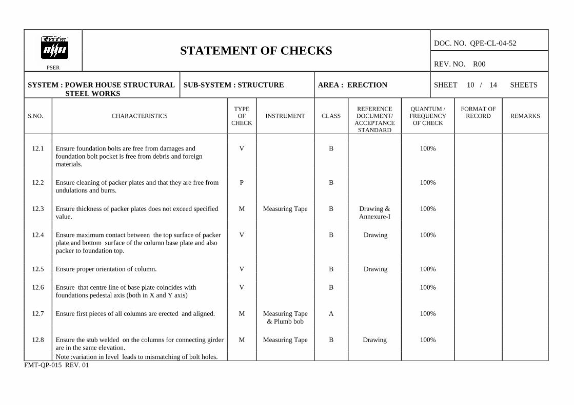
12.1 Ensure foundation bolts are free from damages and
foundation bolt pocket is free from debris and foreign materials.
V B 100%
12.2 Ensure cleaning of packer plates and that they are free from
undulations and burrs. P B 100%
12.3 Ensure thickness of packer plates does not exceed specified
value. M Measuring Tape B Drawing &
Annexure-I 100%
12.4 Ensure maximum contact between the top surface of packer
plate and bottom surface of the column base plate and also packer to foundation top.
V B Drawing 100%
12.5 Ensure proper orientation of column. V B Drawing 100%
12.6 Ensure that centre line of base plate coincides with
foundations pedestal axis (both in X and Y axis) V B 100%
12.7 Ensure first pieces of all columns are erected and aligned. M Measuring Tape
& Plumb bob A 100%
12.8 Ensure the stub welded on the columns for connecting girder
are in the same elevation. M Measuring Tape B Drawing 100%
Note :variation in level leads to mismatching of bolt holes. FMT-QP-015 REV. 01

DOC. NO. QPE-CL-04-52
PSER
STATEMENT OF CHECKS REV. NO. R00
SYSTEM : POWER HOUSE STRUCTURAL STEEL WORKS
SUB-SYSTEM : STRUCTURE
AREA : ERECTION
SHEET 11 / 14 SHEETS
S.NO.
CHARACTERISTICS
TYPE
OF CHECK
INSTRUMENT
CLASS
REFERENCE DOCUMENT/
ACCEPTANCE STANDARD
QUANTUM / FREQUENCY
OF CHECK
FORMAT OF
RECORD
REMARKS
12.9 Ensure the erection of horizontal beams/girders and vertical
bracing (use correct size HSFG/HT bolts and follow the tightening procedure).
M A Drawing & Annexure-I
100%
Note: Site to decide about the horizantal beams/vertical bracings not to be erected for the movement of Cranes or any erection equipment. The left out members shall be erected at the appropriate time
12.10 Check verticality of first piece columns after erection of the
respective connecting adjacent columns. M Plump bob /
Theodolite A Drawing &
Annexure-I 100%
12.11 Ensure proper tightening of foundation bolts with lock nuts. V B Drawing 100% 12.12 Ensure locking of all packer plates by tack welding. V C 100% 12.13 Ensure grouting up to the base plate bottom after ensuring
verticality of columns and cure (Cube test to be carried out) M / V Compressive
Testing m/c B 100% L-09
12.14 Ensure erection of second pieces of all columns. V C Drawing &
Annexure-I 100%
12.15 Ensure erection of interconnecting members. V C Drawing 100% 12.16 Ensure tightness of bolts (HSFG/HT bolts as the case may be) M Torque Wrench B Annexure-I 100%
FMT-QP-015 REV. 01
DOC. NO. QPE-CL-04-52
PSER
STATEMENT OF CHECKS REV. NO. R00
SYSTEM : POWER HOUSE STRUCTURAL STEEL WORKS
SUB-SYSTEM : STRUCTURE
AREA : ERECTION
SHEET 12 / 14 SHEETS
S.NO.
CHARACTERISTICS
TYPE
OF CHECK
INSTRUMENT
CLASS
REFERENCE DOCUMENT/
ACCEPTANCE STANDARD
QUANTUM / FREQUENCY
OF CHECK
FORMAT OF
RECORD
REMARKS
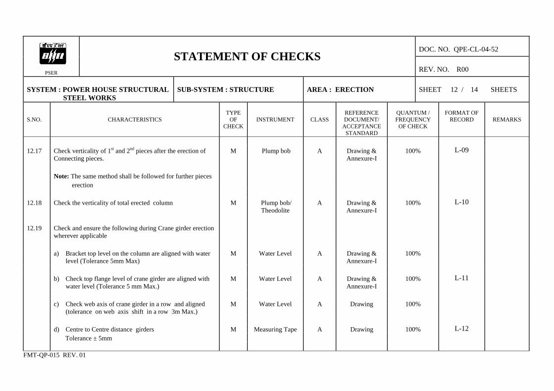
12.17 Check verticality of 1st and 2nd pieces after the erection of
Connecting pieces. M Plump bob A Drawing &
Annexure-I 100% L-09
Note: The same method shall be followed for further pieces
erection
12.18 Check the verticality of total erected column M Plump bob/
Theodolite A Drawing &
Annexure-I 100% L-10
12.19 Check and ensure the following during Crane girder erection
wherever applicable
a) Bracket top level on the column are aligned with water
level (Tolerance 5mm Max) M Water Level A Drawing &
Annexure-I 100%
b) Check top flange level of crane girder are aligned with
water level (Tolerance 5 mm Max.) M Water Level A Drawing &
Annexure-I 100% L-11
c) Check web axis of crane girder in a row and aligned
(tolerance on web axis shift in a row 3m Max.) M Water Level A Drawing 100%
d) Centre to Centre distance girders M Measuring Tape A Drawing 100% L-12 Tolerance ± 5mm
FMT-QP-015 REV. 01

DOC. NO. QPE-CL-04-52
PSER
STATEMENT OF CHECKS REV. NO. R00
SYSTEM : POWER HOUSE STRUCTURAL STEEL WORKS
SUB-SYSTEM : STRUCTURE
AREA : ERECTION
SHEET 13 / 14 SHEETS
S.NO.
CHARACTERISTICS
TYPE
OF CHECK
INSTRUMENT
CLASS
REFERENCE DOCUMENT/
ACCEPTANCE STANDARD
QUANTUM / FREQUENCY
OF CHECK
FORMAT OF
RECORD
REMARKS
12.20 Ensure the following during the erection of roof trusses
a) Proper handling to avoid damage & distortion to
assembled trusses. V C 100%
b) Alignment of bolt holes between columns and truss
gussets. V C Drawing 100%
c) Slope of truss as per drawing. M Spirit Level /
Water Level B Drawing 100%
d) tightness of bolts. M Torque Wrench B Annexure-I 100% e) truss to truss connecting members including purlins V C Drawing 100%
12.21 HSFG bolts tightening a) Ensure HSFG bolts are tightened by calibrated torque
wrenches. M B 100%
b) Check the tightness of HSFG bolts using calibrated
torque wrench. M Torque Wrench B Drawing 100%
FMT-QP-015 REV. 01
DOC. NO. QPE-CL-040
PSER
STATEMENT OF CHECKS REV. NO. R02
SYSTEM : POWER HOUSE STRUCTURAL STEEL WORKS
SUB-SYSTEM : STRUCTURE
AREA : ERECTION
SHEET 14 / 14 SHEETS
S.NO.
CHARACTERISTICS
TYPE
OF CHECK
INSTRUMENT
CLASS
REFERENCE DOCUMENT/
ACCEPTANCE STANDARD
QUANTUM / FREQUENCY
OF CHECK
FORMAT
OF RECORD
REMARKS
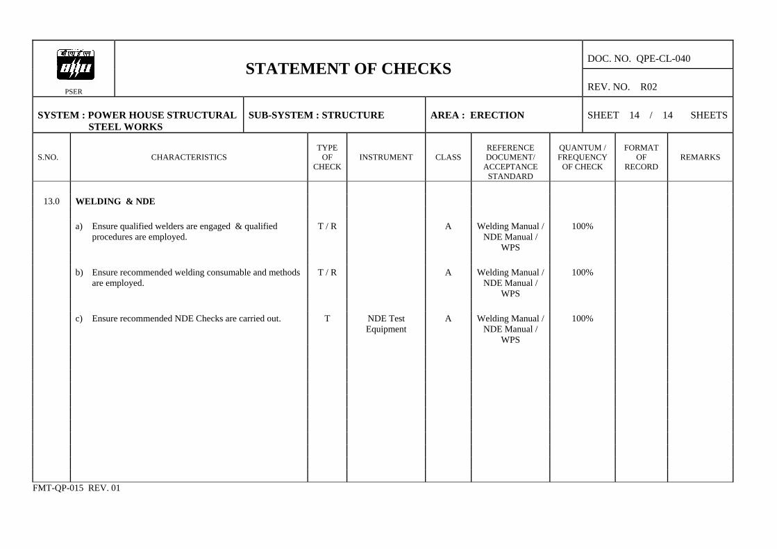
13.0 WELDING & NDE
a) Ensure qualified welders are engaged & qualified
procedures are employed. T / R A Welding Manual /
NDE Manual / WPS
100%
b) Ensure recommended welding consumable and methods
are employed. T / R A Welding Manual /
NDE Manual / WPS
100%
c) Ensure recommended NDE Checks are carried out. T NDE Test
Equipment A Welding Manual /
NDE Manual / WPS
100%
FMT-QP-015 REV. 01
DOC. NO. : QPX-CL-04-52 REV. NO. : R00
PSER
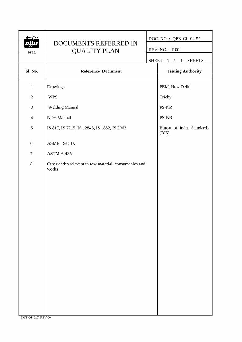
DOCUMENTS REFERRED IN QUALITY PLAN
SHEET 1 / 1 SHEETS
Sl. No.
Reference Document
Issuing Authority
1
2
3
4
5
6.
7.
8.
Drawings WPS Welding Manual NDE Manual IS 817, IS 7215, IS 12843, IS 1852, IS 2062 ASME : Sec IX ASTM A 435 Other codes relevant to raw material, consumables and works
PEM, New Delhi Trichy PS-NR PS-NR Bureau of India Standards (BIS)
FMT-QP-017 REV.00
Annexure - I Doc. No. QPE-CL-04-52 Rev. No. R00 Sheet No. 1 of 3
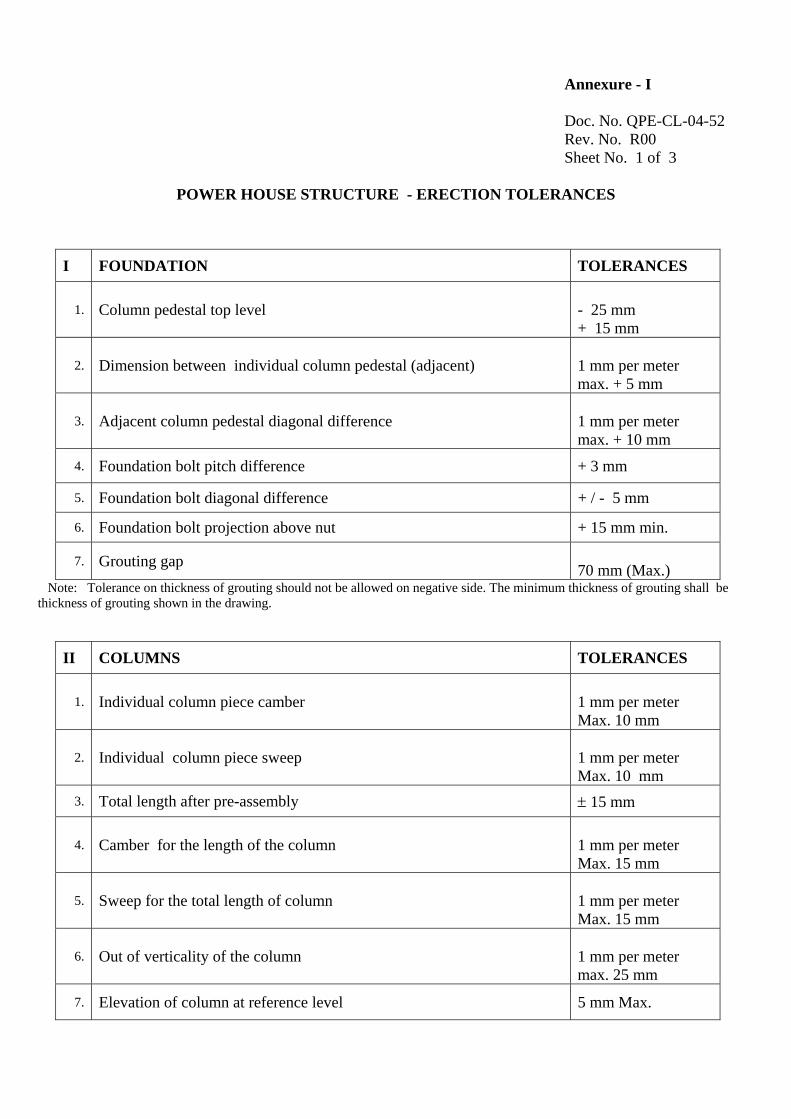
POWER HOUSE STRUCTURE - ERECTION TOLERANCES
I FOUNDATION TOLERANCES
1. Column pedestal top level - 25 mm + 15 mm
2. Dimension between individual column pedestal (adjacent) 1 mm per meter max. + 5 mm
3. Adjacent column pedestal diagonal difference 1 mm per meter max. + 10 mm
4. Foundation bolt pitch difference + 3 mm
5. Foundation bolt diagonal difference + / - 5 mm
6. Foundation bolt projection above nut + 15 mm min.
7. Grouting gap 70 mm (Max.)
Note: Tolerance on thickness of grouting should not be allowed on negative side. The minimum thickness of grouting shall be thickness of grouting shown in the drawing.
II COLUMNS TOLERANCES
1. Individual column piece camber 1 mm per meter Max. 10 mm
2. Individual column piece sweep 1 mm per meter Max. 10 mm
3. Total length after pre-assembly ± 15 mm
4. Camber for the length of the column 1 mm per meter Max. 15 mm
5. Sweep for the total length of column 1 mm per meter Max. 15 mm
6. Out of verticality of the column 1 mm per meter max. 25 mm
7. Elevation of column at reference level 5 mm Max.
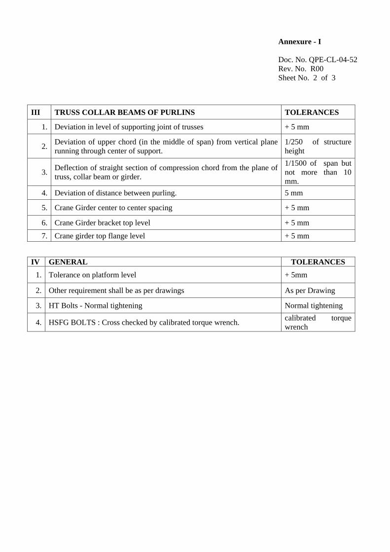
Annexure - I Doc. No. QPE-CL-04-52 Rev. No. R00 Sheet No. 2 of 3
III TRUSS COLLAR BEAMS OF PURLINS TOLERANCES
1. Deviation in level of supporting joint of trusses + 5 mm
2. Deviation of upper chord (in the middle of span) from vertical plane running through center of support.
1/250 of structure height
3. Deflection of straight section of compression chord from the plane of truss, collar beam or girder.
1/1500 of span but not more than 10 mm.
4. Deviation of distance between purling. 5 mm
5. Crane Girder center to center spacing + 5 mm
6. Crane Girder bracket top level + 5 mm
7. Crane girder top flange level + 5 mm
IV GENERAL TOLERANCES 1. Tolerance on platform level + 5mm
2. Other requirement shall be as per drawings As per Drawing
3. HT Bolts - Normal tightening Normal tightening
4. HSFG BOLTS : Cross checked by calibrated torque wrench. calibrated torque wrench
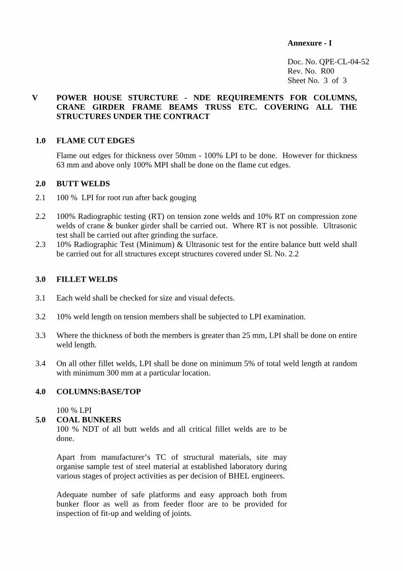
Annexure - I Doc. No. QPE-CL-04-52 Rev. No. R00 Sheet No. 3 of 3
V POWER HOUSE STURCTURE - NDE REQUIREMENTS FOR COLUMNS, CRANE GIRDER FRAME BEAMS TRUSS ETC. COVERING ALL THE STRUCTURES UNDER THE CONTRACT
1.0 FLAME CUT EDGES
Flame out edges for thickness over 50mm - 100% LPI to be done. However for thickness 63 mm and above only 100% MPI shall be done on the flame cut edges.
2.0 BUTT WELDS 2.1 100 % LPI for root run after back gouging
2.2 100% Radiographic testing (RT) on tension zone welds and 10% RT on compression zone welds of crane & bunker girder shall be carried out. Where RT is not possible. Ultrasonic test shall be carried out after grinding the surface.
2.3 10% Radiographic Test (Minimum) & Ultrasonic test for the entire balance butt weld shall be carried out for all structures except structures covered under Sl. No. 2.2
3.0 FILLET WELDS
3.1 Each weld shall be checked for size and visual defects.
3.2 10% weld length on tension members shall be subjected to LPI examination.
3.3 Where the thickness of both the members is greater than 25 mm, LPI shall be done on entire weld length.
3.4 On all other fillet welds, LPI shall be done on minimum 5% of total weld length at random with minimum 300 mm at a particular location.
4.0 COLUMNS:BASE/TOP
100 % LPI
5.0 COAL BUNKERS 100 % NDT of all butt welds and all critical fillet welds are to be
done. Apart from manufacturer’s TC of structural materials, site may organise sample test of steel material at established laboratory during various stages of project activities as per decision of BHEL engineers. Adequate number of safe platforms and easy approach both from bunker floor as well as from feeder floor are to be provided for inspection of fit-up and welding of joints.

Annexure - II
Doc. No. QPE-CL-04-52 Rev. No. R00 Sheet No. 1 of 1
1.0 REQUIREMENT OF PREHEATING
Thickness of thickest part at the point of welding
Other than low hydrogen welding electrodes
Low hydrogen electrodes / submerged arc welding
Upto 20 mm (including) None None
Over 20 mm to 40 mm (including) 65° C 20° C
Over 40 mm to 63 mm (including) 110° C 66° C
Over 63 mm 150° C 110° C
2.0
CUTTING TOLERANCES AND DIMENSIONAL VARIATIONS DURING FABRICATION
AS PER TABLE A1
3.0
TOLARABLE DEVIATIONS OF FARICATED MEMBERS FROM GEOMENTRICAL SHAPE
AS PER TABLE A2
4.0
DEVIATIONS
4.1
ACCEPTABLE DEVIATIONS IN AS FARICATED STEEL STRUCTURES
AS PER TABLE A3
4.2
SPECIFICATION FOR PERMISSIBLE DEVIATION IN BOLT HOLES.
AS PER TABLE A4
4.3
SPECIFICATION FOR PERMISSIBLE DEVIATION OF STRUCTURAL STEEL.
AS PER TABLE A5
4.4
MAXIMUM PERMISSIBLE TOLERANCES IN ERECTED STEEL STRUCTURES.
AS PER TABLE A6
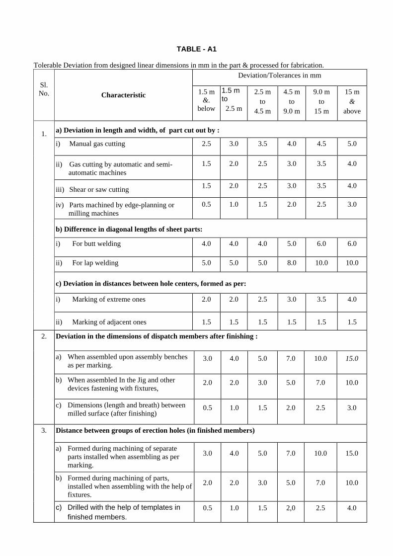
TABLE - A1
Tolerable Deviation from designed linear dimensions in mm in the part & processed for fabrication.
Deviation/Tolerances in mm Sl. No. Characteristic 1.5 m
&. below
1.5 m to
2.5 m
2.5 m to
4.5 m
4.5 m to
9.0 m
9.0 m to
15 m
15 m &
above
a) Deviation in length and width, of part cut out by :
i) Manual gas cutting 2.5 3.0 3.5 4.0 4.5 5.0
ii) Gas cutting by automatic and semi-automatic machines
1.5
2.0
2.5
3.0
3.5
4.0
iii) Shear or saw cutting 1.5 2.0 2.5 3.0 3.5 4.0
iv) Parts machined by edge-planning or milling machines
0.5
1.0
1.5
2.0
2.5
3.0
b) Difference in diagonal lengths of sheet parts:
i) For butt welding
4.0 4.0 4.0 5.0
6.0
6.0
ii) For lap welding 5.0 5.0 5.0 8.0 10.0 10.0
c) Deviation in distances between hole centers, formed as per:
i) Marking of extreme ones
2.0 2.0 2.5 3.0
3.5
4.0
1.
ii) Marking of adjacent ones 1.5 1.5 1.5 1.5 1.5 1.5
Deviation in the dimensions of dispatch members after finishing :
a) When assembled upon assembly benches as per marking.
3.0
4.0
5.0
7.0
10.0
15.0
b) When assembled In the Jig and other devices fastening with fixtures,
2.0
2.0
3.0
5.0
7.0
10.0
2.
c) Dimensions (length and breath) between milled surface (after finishing)
0.5
1.0
1.5
2.0
2.5
3.0
Distance between groups of erection holes (in finished members)
a) Formed during machining of separate parts installed when assembling as per marking.
3.0
4.0
5.0
7.0
10.0
15.0
b) Formed during machining of parts, installed when assembling with the help of fixtures.
2.0
2.0
3.0
5.0
7.0
10.0
3.
c) Drilled with the help of templates in finished members.
0.5
1.0
1.5
2,0
2.5
4.0

TABLE A.2
Tolerable deviations of fabricated member from designed geometrical shape
Deviation S. No. Characteristic Remarks Curvature of assembly Parts
a) Gap between a sheet and a steel rule face over 1 m length
1.5 mm
1.
b) Gap between a taut string and vertex face of an angle flange or web of channel and joist.
0.001 L, but not greater than 10 mm L - length of member
Deviation of edge line steel sheet parts from theoretical profile:
a) During butt and toe welding. 2 mm
2.
b) During lap welding 5 mm
Deviation of radius of the bend:
a) Clearance between template and the surface of rolled sheet flange or face of cold bend profile.
2 mm
Template length (1.5 m along the curve)
b) Clearance between template and the surface of rolled sheet flange or face of hot bend profile
3 mm -do-
c) Ellipticity (difference of diameters) in space sheet structures.
0.005D
D-diameter of circumference
3.
d) Ellipticity (difference of diameters) in erection joints 0.003D -do-
Deformation of dispatch members: a) Inclination of flanges with the web:
i) at Junction point 0.005b b-width of flange
ii) at other places O.Olb b-width of flange
b) Transverse bending of flanges:
i) at junction with members 0.005b b- width of flange
ii) at other places O.Olb b-width of flange
c) Warping of the web
0.003h
h-depth of the member
4.
d) Sag of member
L/750 but not more than 15mm
L-length of the member
5. Other Deviations:
a) Shifting of axes or riveting / bolting lines for lattice structures from theoretical eccentricity.
3.0 mm
b) Inclination of the milled surface from designed position.
1/1500

TABLE-A.3
Acceptance Deviations in as fabricates steel structures. Sl. No.
Characteristic Deviation / Tolerance
COLUMNS
Deviation in length 'L' measured distance from bottom surface of the column footings, to the group of holes for trusses, fasteners, collar beams, purlins and other elements to be connected to column. When L is under 10 m ± 10 mm
a) When L is over 10 m ± l5 mm
Deviation in distance 'L' from bottom surface of the column footing to the top of crane brackets.
When L is under 10 m ± 5 mm
b) when L is over 10 m ± 10 mm
c)
Deviation in distance from bearing surface of the bracket to the first fastener of the element to the connected to column.
± 1 mm
d)
Deviation in distance between any group of holes for connection of bracings to column.
± 2 mm
e)
Sag of column element (curvature)
1/1000 of length element but not more
f) Difference in web depth of column
i) At splice joint ± 2 mm
ii) At any other location ± 10 mm
1.
g)
Deviation in distance from supporting surface of milled end of the despatch element of column to the clear or heating plate or column to the cleat or seating plate for fastening of collar beams, purlins, girders. etc. (Fish plates, brackets)
± 3 mm
TRUSSES
a) Deviation in span 'L' of the truss between end erection holes in gussets of supporting units or between external planes of supporting gussets or angles when trusses are resting on brackets or supports:
When L is under 25 m ± 7 mm
When L is over 25 m
1/2500 but not more than 10 mm
b) b) Deviation in distance between the centres of holes or webs of angles for fastening bracing, purlins, monitors etc
± 3 mm
c) Deviation in distance between the first row of erection holes and the bearing surface at cleat or seating plate.
± 1 mm
d) Distance between holes for fasteners to top and bottom chords of trusses on
supports. ± 3 mm
2.
e) Sag of separate elements between node points.
1/1500 of length of element but not more than 10 mm.
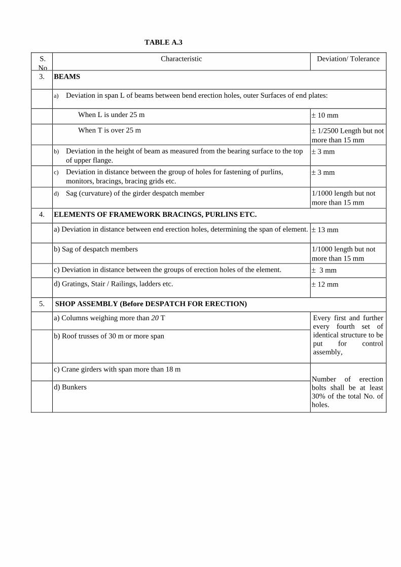
TABLE A.3
S. No
Characteristic Deviation/ Tolerance
3. BEAMS
a) Deviation in span L of beams between bend erection holes, outer Surfaces of end plates:
When L is under 25 m ± 10 mm
When T is over 25 m
± 1/2500 Length but not more than 15 mm
b) Deviation in the height of beam as measured from the bearing surface to the top of upper flange.
± 3 mm
c) Deviation in distance between the group of holes for fastening of purlins, monitors, bracings, bracing grids etc.
± 3 mm
d) Sag (curvature) of the girder despatch member
1/1000 length but not more than 15 mm
4. ELEMENTS OF FRAMEWORK BRACINGS, PURLINS ETC.
a) Deviation in distance between end erection holes, determining the span of element.
± 13 mm
b) Sag of despatch members
1/1000 length but not more than 15 mm
c) Deviation in distance between the groups of erection holes of the element. ± 3 mm
d) Gratings, Stair / Railings, ladders etc. ± 12 mm
5. SHOP ASSEMBLY (Before DESPATCH FOR ERECTION)
a) Columns weighing more than 20 T
b) Roof trusses of 30 m or more span
Every first and further every fourth set of identical structure to be put for control assembly,
c) Crane girders with span more than 18 m
d) Bunkers
Number of erection bolts shall be at least 30% of the total No. of holes.
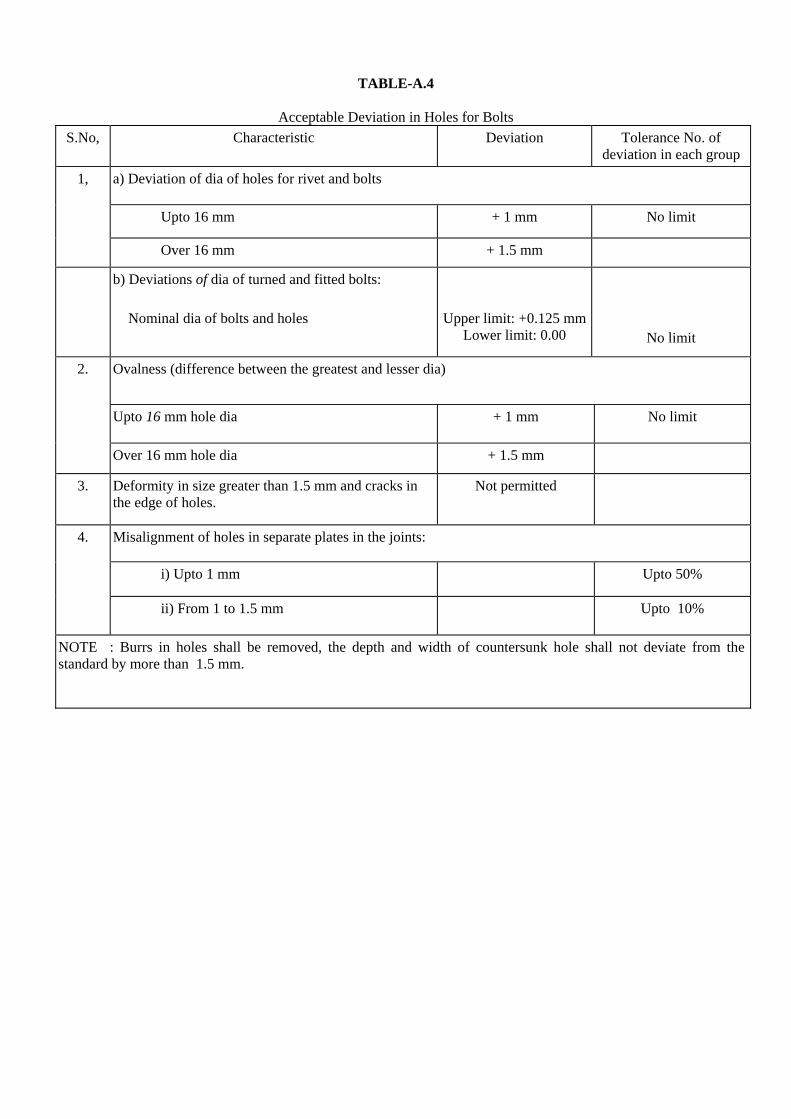
TABLE-A.4
Acceptable Deviation in Holes for Bolts S.No, Characteristic Deviation
Tolerance No. of
deviation in each group
a) Deviation of dia of holes for rivet and bolts
Upto 16 mm + 1 mm No limit
1,
Over 16 mm + 1.5 mm
b) Deviations of dia of turned and fitted bolts: Nominal dia of bolts and holes
Upper limit: +0.125 mm Lower limit: 0.00
No limit
Ovalness (difference between the greatest and lesser dia)
Upto 16 mm hole dia + 1 mm No limit
2.
Over 16 mm hole dia + 1.5 mm
3.
Deformity in size greater than 1.5 mm and cracks in the edge of holes.
Not permitted
Misalignment of holes in separate plates in the joints:
i) Upto 1 mm Upto 50%
4.
ii) From 1 to 1.5 mm
Upto 10%
NOTE : Burrs in holes shall be removed, the depth and width of countersunk hole shall not deviate from the standard by more than 1.5 mm.
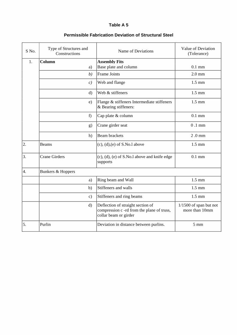
Table A 5
Permissible Fabrication Deviation of Structural Steel
S No. Type of Structures and Constructions Name of Deviations Value of Deviation
(Tolerance)
1. Column Assembly Fits a) Base plate and column 0.1 mm b) Frame Joints 2.0 mm
c) Web and flange 1.5 mm
d) Web & stiffeners 1.5 mm
e) Flange & stiffeners Intermediate stiffeners & Bearing stiffeners:
1.5 mm
f) Cap plate & column 0.1 mm
g) Crane girder seat 0 .1 mm
h) Beam brackets 2 .0 mm
2.
Beams
(c), (d),(e) of S.No.l above
1.5 mm
3. Crane Girders (c), (d), (e) of S.No.l above and knife edge supports
0.1 mm
4. Bunkers & Hoppers
a) Ring beam and Wall 1.5 mm
b) Stiffeners and walls 1.5 mm
c) Stiffeners and ring beams 1.5 mm
d)
Deflection of straight section of compression c -rd from the plane of truss, collar beam or girder
1/1500 of span but not more than 10mm
5. Purlin Deviation in distance between purlins. 5 mm

TABLE -A6
Maximum Permissible & Tolerances in Erected Steel Structures
Sl. No.
Description Tolerance
1 Erected steel columns:
i) Deviation of column axis at foundation top level with respect to true axis: a) in longitudinal direction b) in lateral direction
± 5 mm
± 5 mm
ii) Deviation in the level of bearing surface of columns at foundation top with respect to true level
± 5 mm
iii) Out of plumbness (verticality) of column axis from true vertical axis, as measured at column top:
a) For columns without any special requirements:
1) upto and including 30 m height
± H/1000 or ± 25 mm whichever is less
2) over 30 m height
± H/1200 or ± 35 mm whichever is less
b) For column with special requirements like cranes or such similar requirements:
1) Upto and including 30 m height
± H/1000 or ± 20 mm whichever is less
2) Over 30 m height ± H/1500 or ± 25 mm whichever is less
iv) Deviation in straightness in longitudinal and transverse of column at any point along the height.
± H/1500 or ± 10 mm whichever is less
v) Difference in the erected positions of adjacent pairs of columns along length or across width of building prior to connecting trusses/ beams with respect to true distance.
± 5 mm
vi) Deviation in any bearing or seating level with respect to true level. ± 5 ram
vii) Deviation in difference in bearing levels of a member on adjacent pair of columns both across and along the building.
± 5 mm
NOTE 1. Tolerance specified under iii (a) and iii (b) should be read in conjunction with iv and v. 2. 'H' is the column height in mm.

TABLE- 6 (Contd.)
S. No. Description Tolerance
Erected Steel trusses
i) Shift, at the centre of span of top chord member with respect to the vertical plane passing through the centre of bottom chord.
± 1/250 of height of truss in mm at centre of span or ± 15 mm Whichever is less
ii) Lateral shift of top chord of truss at the centre of span from the vertical plane passing through the centre of supports of the truss
± 1/1500 of span of truss in mm or 10 mm whichever is less
iii) Lateral shift in location of truss from its true axis in plan
± 10 mm
iv) Lateral shift in location of purlin From true position ± 5 mm
2.0
v) Deviation in difference or bearing levels of trusses from the true difference.
± 1/1200 of span of truss in mm or ± 20 mm whichever is less
Erected Crane Girder and Rails
i) Shift in the centre line of crane rail with respect to centre line of web crane girder.
± {(Web thk in mm) + 2mm} / 2
ii) Shift in plan of alignment of crane rail with respect to true axis of crane rail at any point,
± 5 mm
iii) Deviation in crane track gauge with respect to the gauges
a) For track gauge up to and including 15 mm + 5 mm
b) For track gauge more than 15 m
± (5 + 0.25(S-15)) mm subject to a maximum of ±10 mm, where S in meters is true track gauge.
iv) Deviation in the crane rail level at any point from true level ± 10 mm
v) Difference in levels between crane track rails at:
a) Supports of crane girders 15 mm
b) mid span of crane girders 20 mm
3.
vi) Relative shift of crane rail surface at a joint in plan and elevation.
2 mm subject to grinding of surfaces for smooth transition

PSER
RECORED OF QUALITY CHECKS
SHEET NO. OF QPI
CHECK
NO.
RESULTS
ACHIEVED OK / NOT OK
DRAWING / DOCUMENT REFERENCE
FORMAT OF
RECORD
CHECKED BY SIGN. & DATE
ACCEPTED BY SIGN. & DATE
REMARKS
Note : Any protocol made is to be numbered & mentioned in “Format of Record” column.
DOC. NO. QPE-CL-04-52
PROJECT
SYSTEM
SUB-SYSTEM
AREA
REV. NO. R00
UNIT NO.
LOG SHEET NO. L-00
RATING
SHEET / SHEETS
FMT-QP-007 REV. 00

INSTRUMENT REG. NO.
DATE OF INSPECTION
PSER
DRAWING / DOCUMENT REF.
QUALITY CERTIFICATE OF CIVIL FOUNDATIONS
Project : Foundation for :
Unit No. : BHEL input
Customer : Date Reference :
Sub-contractor : Main Construction
Drawing No. :
Construction period : From :…………… to ………… Handed over to BHEL by sub-contractor
Status : Complete / Incomplete on (Date) ………………………
Certified that the above foundation has been constructed as IS 456. It is declared fit for erection work
of …………………………………………………… based on the following details :
1. Foundation cast -- As per IS
2. Shuttering and re-enforcement As per construction Drawing ……………………
3. Test for strength of concrete As per IS 456
Results Acceptable / Not Acceptable
4. Curing time ………………….. days.
5. Dimensions, sizes position of inserts and pockets, verticality, level, etc. have been checked,
logged and found OK.
6. Details of defects detected visually / by NDE, pre-disposed non-conformances and corrective
action are enclosed. (Reference : Annexure-I)
NAME
SIG. / DATE DOC. NO. QPE-CL-04-52
PROJECT
CHECKED BY
REV. NO. R00
UNIT NO.
ACCEPTED BY
LOGSHEET NO. L-01
RATING
CUSTOMER
SHEET 1 / 1 SHEETS
FMT-QP-008 REV. 00

INSTRUMENT REG. NO.
DATE OF INSPECTION
PSER
DRAWING / DOCUMENT REF.
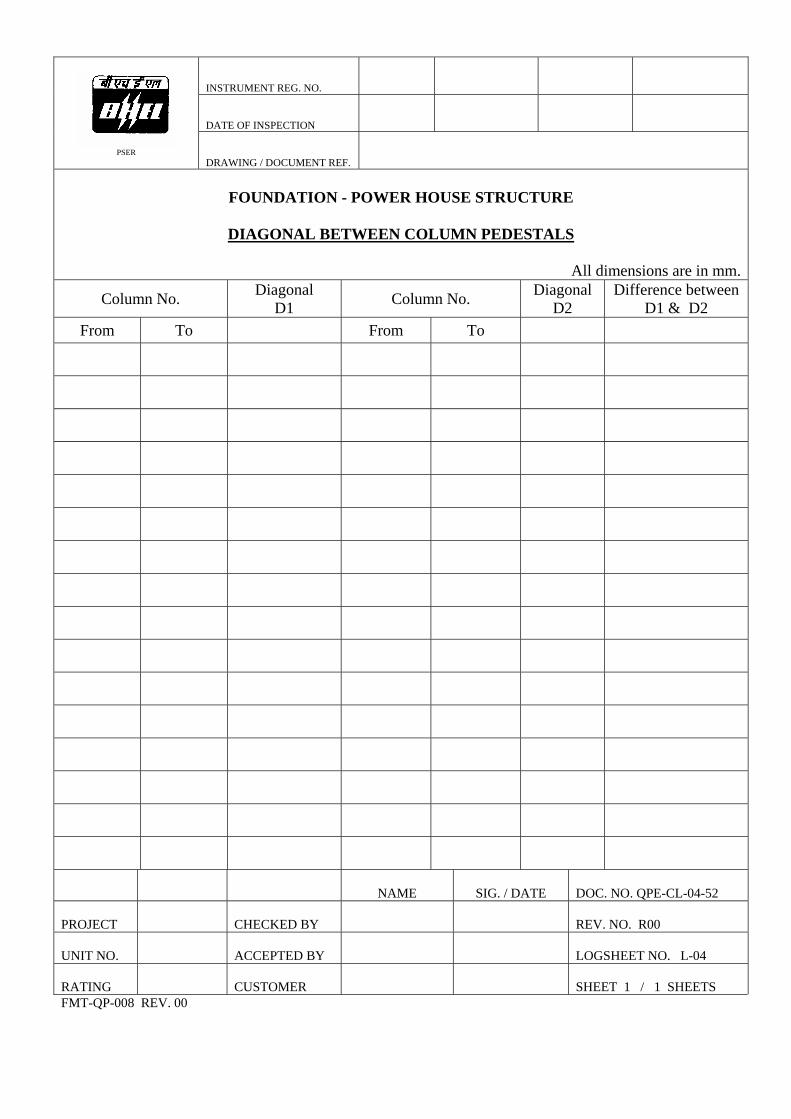
FOUNDATION - POWER HOUSE STRUCTURE
TOP OF PEDESTALS
Elevation of top pedestal as per drawing …………………… mm.
All dimensions are in mm.Column No. Top Elevation
measurement Deviation from drawing value
Column No. Top Elevation measurement
Deviation from drawing value
NAME
SIG. / DATE DOC. NO. QPE-CL-04-52
PROJECT
CHECKED BY
REV. NO. R00
UNIT NO.
ACCEPTED BY
LOGSHEET NO. L-02
RATING
CUSTOMER
SHEET 1 / 1 SHEETS
FMT-QP-008 REV. 00
INSTRUMENT REG. NO.
DATE OF INSPECTION
PSER
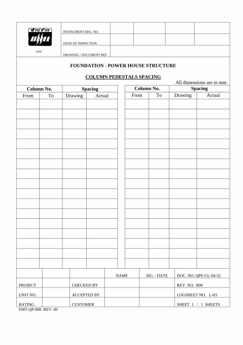
DRAWING / DOCUMENT REF.
FOUNDATION - POWER HOUSE STRUCTURE
COLUMN PEDESTALS SPACING
All dimensions are in mm. Column No. Spacing Column No. Spacing
From To Drawing Actual From To Drawing Actual
NAME
SIG. / DATE
DOC. NO. QPE-CL-04-52
PROJECT
CHECKED BY
REV. NO. R00
UNIT NO.
ACCEPTED BY
LOGSHEET NO. L-03
RATING
CUSTOMER
SHEET 1 / 1 SHEETS
FMT-QP-008 REV. 00
INSTRUMENT REG. NO.
DATE OF INSPECTION
PSER
DRAWING / DOCUMENT REF.
FOUNDATION - POWER HOUSE STRUCTURE
DIAGONAL BETWEEN COLUMN PEDESTALS
All dimensions are in mm.
Column No. Diagonal D1 Column No. Diagonal
D2 Difference between
D1 & D2 From To From To
NAME
SIG. / DATE DOC. NO. QPE-CL-04-52
PROJECT
CHECKED BY
REV. NO. R00
UNIT NO.
ACCEPTED BY
LOGSHEET NO. L-04
RATING
CUSTOMER
SHEET 1 / 1 SHEETS
FMT-QP-008 REV. 00

INSTRUMENT REG. NO.
DATE OF INSPECTION
PSER
DRAWING / DOCUMENT REF.
PITCH DISTANCE OF FOUNDATION BOLTS & DIAGONALS
N . TYPE -I TYPE -II
TYPE - I
Column No. A B a1 a2 1 2
As per drawing TYPE - II
Column No. A B a1 a2 1 2As per drawing
NA PROJECT
CHECKED BY
UNIT NO.
ACCEPTED BY
RATING
CUSTOMER
FMT-QP-008 REV. 00
3 4 1' 2' 3' 4' D1 D2
3 4 1' 2' 3' 4' D1 D2
ME
SIG. / DATE
DOC. NO. QPE-CL-04-52
REV. NO. R00
LOGSHEET NO. L-05
SHEET 1 / 4 SHEETS

INSTRUMENT REG. NO.
DATE OF INSPECTION
PSER
DRAWING / DOCUMENT REF.
PITCH DISTANCE OF FOUNDATION BOLTS & DIAGONALS
N TYPE - III
Column No. A B a1 a2 1 2 3 4 1' 2' 3' 4' D1 D2 As per drawing
NAME
SIG. / DATE DOC. NO. QPE-CL-04-52
PROJECT
CHECKED BY
REV. NO. R00
UNIT NO.
ACCEPTED BY
LOGSHEET NO. L-05
RATING
CUSTOMER
SHEET 2 / 4 SHEETS
FMT-QP-008 REV. 00
INSTRUMENT REG. NO.
DATE OF INSPECTION
PSER
DRAWING / DOCUMENT REF.
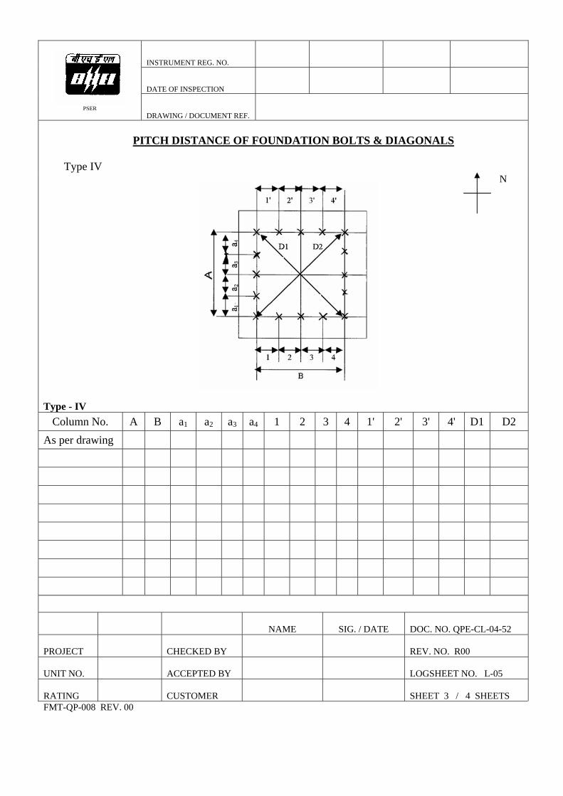
PITCH DISTANCE OF FOUNDATION BOLTS & DIAGONALS
Type IV
N Type - IV
Column No. A B a1 a2 a3 a4 1 2 3 4 1' 2' 3' 4' D1 D2 As per drawing
NAME
SIG. / DATE DOC. NO. QPE-CL-04-52
PROJECT
CHECKED BY
REV. NO. R00
UNIT NO.
ACCEPTED BY
LOGSHEET NO. L-05
RATING
CUSTOMER
SHEET 3 / 4 SHEETS
FMT-QP-008 REV. 00

INSTRUMENT REG. NO.
DATE OF INSPECTION
PSER
DRAWING / DOCUMENT REF.
PITCH DISTANCE OF FOUNDATION BOLTS & DIAGONALS
Type - V
Type-V
Column No.
PROJECT UNIT NO.
RATING
FMT-QP-008 REV. 00
A B a1 a2 a3 a4 b1 b2 b3 b4 d1 d2
NAME
SIG. / DATE
DOC. NO. QPE-CL-04-52
CHECKED BY
REV. NO. R00
ACCEPTED BY
LOGSHEET NO. L-05
CUSTOMER
SHEET 4 / 4 SHEETS

INSTRUMENT REG. NO./TAG NO.
DATE OF INSPECTION
PSER
DRAWING / DOCUMENT REF.
CAMBER, SWEEP AND LENGTH OF COLUMN PIECES
INDIVIDUAL PIECE TOLERANCE : 1mm / M Max. 10 mm
Column No. Camber Sweep Length
Piece No. T M B T M B
T – Top of the Piece M – Middle of the Piece B – Bottom of the Piece
NAME DOC. NO. QPE-CL-04-52
SIG./DATE
PROJECT
REV. NO. R 00 CHECKED BY
UNIT NO.
ACCEPTED BY
LOG SHEET NO. L-06
RATING
CUSTOMER SHEET 1 / 1 SHEETS
FMT-QP-008 REV.00

INSTRUMENT REG. NO.
DATE OF INSPECTION
PSER
DRAWING / DOCUMENT REF.
TRIAL ASSEMBLY OF COLUMN PIECES
COLUMN NO. : Elevation Level From Bottom
Assembled Piece
Tolerance 1 mm / M Max. 15 mm
Elevation Level From Bottom
Assembled Piece Tolerance 1 mm / M Max.
15 mm
Note : Measure at every 5 Meter level. (Fix Piano wire to full length of column) Measure the reading and only deviation in "+" or "_" Values
J2 J3 J4 J5 J1 J6
Match mark
TOTAL LENGTH : As Per Drg. MEASURED : DIFFERENCE : TOLERANCE : ± 15 mm
NAME
SIGNATURE / DATE
DOC. NO. QPE-CL-04-52
PROJECT
CHECKED BY
REV. NO. R00
UNIT NO.
ACCEPTED BY
LOG SHEET NO. L-07
RATING
CUSTOMER
SHEET 1 / 1 SHEETS
FMT-QP-009 REV. 00

INSTRUMENT REG. NO./TAG NO.
DATE OF INSPECTION
PSER
DRAWING / DOCUMENT REF.
ROOF TRUSS PRE – ASSEMBLY
A & C – End plate at top angle side.
B & D – End plate at bottom angle side.
SLOPE at “ D ” .
Slope actual
As Per Drawing
CAMBER AND SWEEP
LOCATION
CHAMBER
SWEEP
Match Mark : Indicate OK if it is correct and if any deviation inform through SAR.
Location
Match Mark
TOTAL LENGTH
As Per Drawing Measured Difference Tolerance
5 mm ±
NAME
SIG./DATE
DOC. NO. QPE-CL- 04-52
PROJECT Y
REV. NO. R 00
CHECKED B
UNIT NO.
ACCEPTED BY
LOG SHEET NO. L-08
CUSTO E
/ 1 SHEETS RATING M R
SHEET 1
FMT-QP-008 REV.00

INSTRUMENT REG. NO./TAG NO.
DATE OF INSPECTION
PSER
DRAWING / DOCUMENT REF.
GROUTING GAP
(All Measurements in mm) Colum No. Colum No. Colum No. n n n
NAME
SIG./DATE DOC. NO. QPE-CL-04-52
PROJECT CHECKED BY
REV. NO. R 00
UNIT NO. ACCEPTED BY
LOG SHEET NO. L-09
RATING
CUSTOMER
SHEET 1 / 1 SHEETS
FMT-QP-008 REV.00
INSTRUMENT REG. NO./TAG NO.
DATE OF INSPECTION
PSER
DRAWING / DOCUMENT REF.
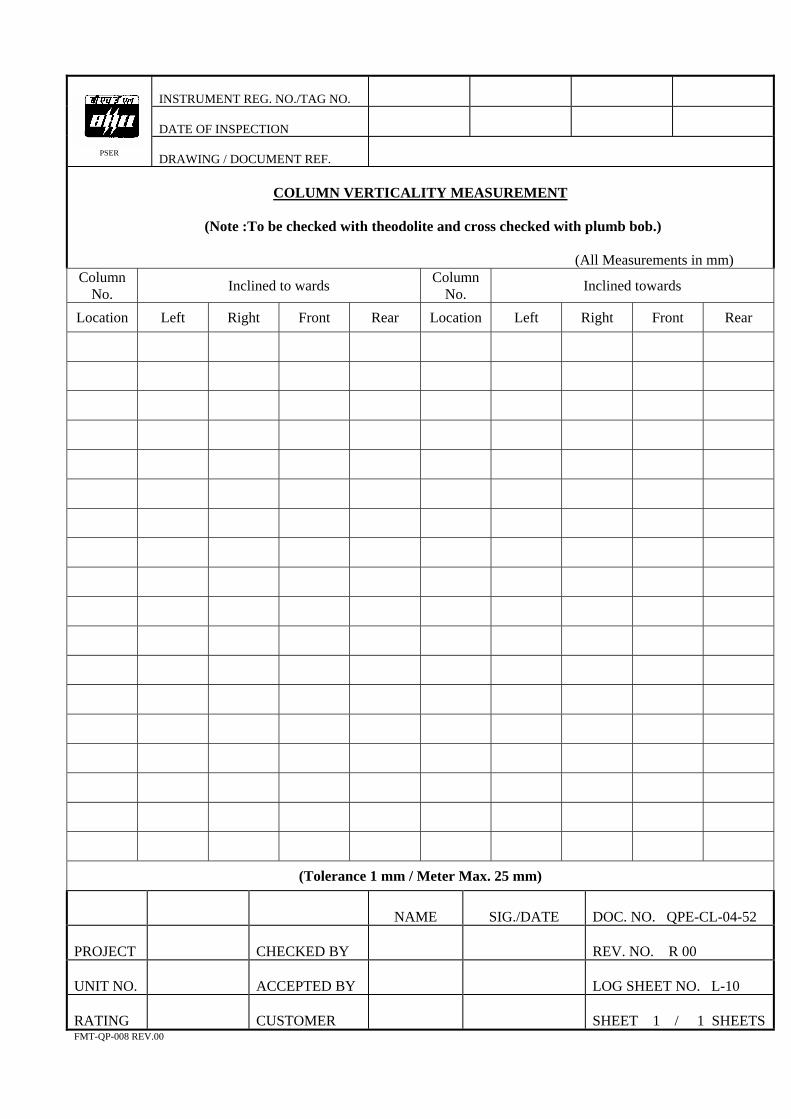
VERTICALIT UREMENTCOLUMN Y MEAS
(Note :To be checked with ecked with bob.)
(All Measurements in mm)
theodolite and cross ch plumb
Column No. Inclined to wards Column
No. Inclined towards
Location Left Right Front Rear Location Left Right Front Rear
(Tolerance 1 mm / Meter Max. 25 mm)
NAME
SIG./DATE
OC. NO. QPE-CL-04-52
D PROJECT
CHECKED BY
REV. NO. R 00
UNIT NO. ACCEPTED BY
LOG SHEET NO. L-10
RATING
CUSTOMER
SHEET 1 / 1 SHEETS
FMT-QP-008 REV.00
INSTRUMENT REG. NO./TAG NO.
DATE OF INSPECTION
PSER
DRAWING / DOCUMENT REF.
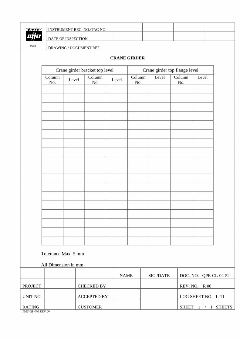
CRANE GIRDER
Crane girder bracket top level Crane girder top flange level Column
No. Level Column No. Level Column
No. Level Column
No. Level
Tolerance Max. 5 mm All Dimension in mm.
NAME
SIG./DATE
OC. NO. QPE-CL-04-52 D
CHECKED BY
REV. NO. R 00 PROJECT
UNIT NO.
ACCEPTED BY
LOG SHEET NO. L-11
RATING CUSTOMER
SHEET 1 / 1 SHEETS
FMT-QP-008 REV.00
INSTRUMENT REG. NO./TAG NO.
DATE OF INSPECTION
PSER
DRAWING / DOCUMENT REF.
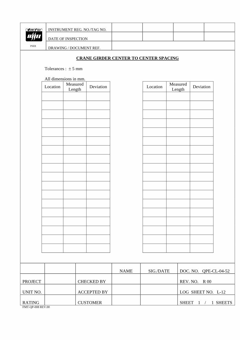
N CENTER T CE CCRA E GIRDER O NTER SPA ING
Tolerances : ± 5
All dimensions in mm.
mm
Location Measured Length Deviation Location Measured
Length Deviation
NAME
SIG./DATE OC. NO. QPE-CL-04-52
D
PROJECT
CHECKED BY
REV. NO. R 00
UNIT NO.
ACCEPTED BY
LOG SHEET NO. L-12
RATING
CUSTOMER
SHEET 1 / 1 SHEETS
FMT-QP-008 REV.00