theconstituentequationsofpiezoelectriccantilevered … ·...
TRANSCRIPT

JOURNAL OF THEORETICAL
AND APPLIED MECHANICS
55, 1, pp. 69-86, Warsaw 2017DOI: 10.15632/jtam-pl.55.1.69
THE CONSTITUENT EQUATIONS OF PIEZOELECTRIC CANTILEVERED
THREE-LAYER ACTUATORS WITH VARIOUS EXTERNAL LOADS
AND GEOMETRY
Grzegorz Mieczkowski
Bialystok University of Technology, Białystok, Poland
e-mail: [email protected]
This paper presents test results for deformation conditions of three-layer, piezoelectric can-tilever converters subjected to various electrical and mechanical boundary conditions. Ageneral solution has been developed based on implementation of piezoelectric triple seg-ments (PTS) to the beam. A working mechanism and conditions for strain of the PTSsegment have been determined. Basing on the general solution, for the cantilever actuatorsubjected to an external force (of single and dual PTS segments) and a uniform load (ofsingle PTS segment), particular solutions have also been developed. Moreover, dimensionlessfrequencies of the oscillating motion for the analyzed converters have been determined. Inthe next step, the influence of such factors as length, quantity and position of PTS segments,their relative stiffness and unit weight on values of the obtained frequencies of vibration ha-ve been defined. The resulting analytical solutions have been compared with the developedFEM solution.
Keywords: piezoelectric bender, constitutive equations, deflection, analytical solutions
1. Introduction
Piezoelectric transducers have been used over the years in many devices. These are exploitedas sensors (Stefanescu, 2011), actuators (Tzou, 1999), energy harvesters (Liu et al., 2014) ordynamic eliminators (Przybyłowicz, 1999). Their working principle is based on the conversion ofelectric energy to mechanical or other way around (Bush-Vishniac, 1999). The relation betweenstrain and electric field is defined by constitutive equations ((Curie and Curie, 1880; Berlincourtet al., 1964).A significant aspect influencing the functionality and durability of converters is selection of
a proper piezoelectric material. The properties of typical piezoelectric materials are presentedin papers by Kawai (1969), Rajabi et al. (2015).Another important factor is a static characteristic of the converter. When designing piezoelec-
tric converters for specific application, it is necessary to define and solve adequate simultaneousequations. These equations bound together geometrical properties, material properties and phy-sical parameters such as force, deflection and electric field. Solving such simultaneous equationsis very difficult. Materials and geometrical inhomogeneity of the converter global structure andanisotropy of piezoelectric materials forces the use of some reductions. Smits et al. (1991), byusing energetic methods, formed and solved constitutive equations for a converter made of twolayers of even length (piezoelectric bimorph). In the paper by Wang and Cross (1999) there isan issue of a three-layer converter extended and solved, whereas in (Xiang and Shi, 2008) – amulti-layer one. The static characteristics of two-layer converters with different length of layersare shown in (Park and Moon, 2005; Raeisifard et al., 2014; Mieczkowski, 2016).Piezoelectric converters as well as other elastic bodies having mass are prone to vibrations.
Therefore, it is necessary to define the nature of their oscillating motion. Many authors have

70 G. Mieczkowski
dealt with this issue. Chen et al.(1998), Askari Farsangi et al. (2013) studied free vibrations ofpiezoelectric laminated plates presented, whereas Clare et al. (1991)analysed a simply supportedbeam with piezoelectric patches. Also, analyses of dynamic characteristics of transducers whereforced vibration occurred are shown in papers by Rouzegar and Abad (2015), Bleustein andTiersten (1968), Djojodihardjo et al. (2015). Dynamical aspects of converters with the piezo-electric patches, including control strategy, were considered by Tylikowski (1993), Pietrzakowski(2000, 2001), Buchacz and Płaczek (2009).
It is a very rare case that in literature one can find results of tests describing the influence ofgeometrical and material characteristics, number and location of piezoelectric patches on staticdeflection and free vibration.
In such cases, in order to determine electromechanical behaviour of the converter, usuallythe FEM-based analyses are carried out, see (Rahmoune and Osmont, 2010; Mieszczak et al.,2006). However, carrying out this type of analyses is very work-consuming and the solution maybe subjected to high error.
Therefore, the main purpose of the present paper is to develop a simple analytical method fordetermining deflection in function of mechanical and electric loads. By design, the piezoelectricconverters have individual components (layers) of different length and the piezoelectric layer canbe divided, which is an extension to the researches shown in papers by Smits et al. (1991), Wangand Cross (1999), Xiang and Shi (2008), where lengths of the beam element and piezoelectriclayers were equal, see Fig. 1.
Fig. 1. Three-layer piezoelectric converter, 1 – beam, 2 – piezoelectric elements, 3 – piezoelectric triplesegment PTS
The proposed method involves the implementation of modules to a homogeneous beam, fur-ther referred to as the piezoelectric triple segment (PTS). This allows including a local change instiffness and strain caused by the transverse piezoelectric effect within the analytical descriptionof the beam deflection.
In view of material and geometric discontinuity in the analyzed transducers, natural fre-quencies of oscillating motion turn out to be different than those in the homogeneous beam.Therefore, the next aim of the paper is analysis of dynamical behavior of such converters. Inthe present work, examination similar to that carried out by Clare et al. (1991) is conducted.It is extended by analysis of the influence of the number, length and location of piezoelectricsegments and their material properties on the natural frequency values.
In order to verify the correctness of the solutions, it is required to compare the obtainedresults with experimental data or results obtained using other methods. Therefore, for converterswith the diversified material and geometric structure, FEM simulations have been made andcompared with the obtained analytical results.
The constituent equations of piezoelectric cantilevered three-layer actuators... 71
2. Analytical results
2.1. Basic assumptions
The converters analysed in this work are treated as a homogeneous (one-layer) beam withlocally implemented piezoelectric triple segments PTS (Fig. 1). The PTS is made up of threecomponents – two piezoelectric and one non-piezoelectric element. The non-piezoelectric layerthickness is the same as the beam thickness. The beam and the PTS both have the same width.In order to simplify the mathematical model, the following assumptions are made:
• bending of the element takes place according to Euler’s hypothesis, and radii of curvaturesof the deflected components are identical,
• in the connection plane between components there is no intermediate layer and no slidingoccurs,
• in the piezoelectric layer, the transverse piezoelectric effect 1-3 takes place causing clearbending.
2.2. General solution to the piezoelectric converter with implemented PTS segment
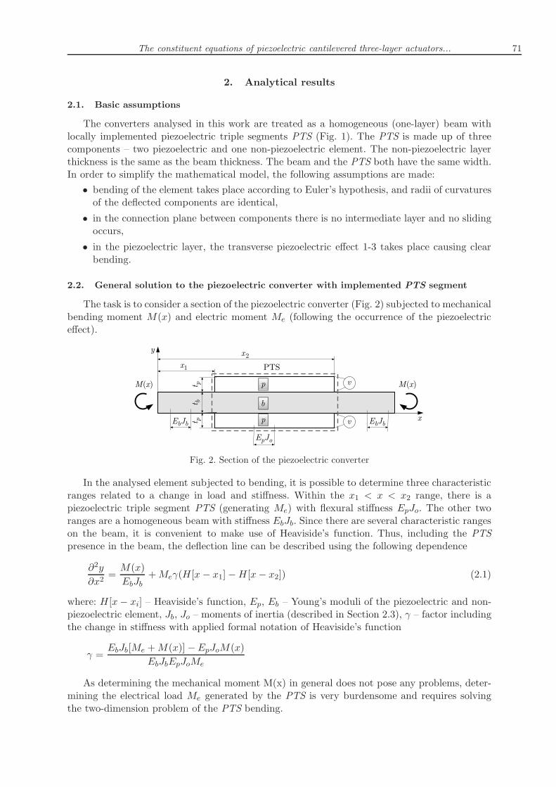
The task is to consider a section of the piezoelectric converter (Fig. 2) subjected to mechanicalbending moment M(x) and electric moment Me (following the occurrence of the piezoelectriceffect).
Fig. 2. Section of the piezoelectric converter
In the analysed element subjected to bending, it is possible to determine three characteristicranges related to a change in load and stiffness. Within the x1 < x < x2 range, there is apiezoelectric triple segment PTS (generating Me) with flexural stiffness EpJo. The other tworanges are a homogeneous beam with stiffness EbJb. Since there are several characteristic rangeson the beam, it is convenient to make use of Heaviside’s function. Thus, including the PTSpresence in the beam, the deflection line can be described using the following dependence
∂2y
∂x2=M(x)
EbJb+Meγ(H[x− x1]−H[x− x2]) (2.1)
where: H[x− xi] – Heaviside’s function, Ep, Eb – Young’s moduli of the piezoelectric and non-piezoelectric element, Jb, Jo – moments of inertia (described in Section 2.3), γ – factor includingthe change in stiffness with applied formal notation of Heaviside’s function
γ =EbJb[Me +M(x)] −EpJoM(x)
EbJbEpJoMe
As determining the mechanical moment M(x) in general does not pose any problems, deter-mining the electrical load Me generated by the PTS is very burdensome and requires solvingthe two-dimension problem of the PTS bending.

72 G. Mieczkowski
2.3. Piezoelectric triple segment PTS
The task is to consider the segment PTS (Fig. 3) with constant width b consisting of non--piezoelectric (2) and piezoelectric layers (1) and (3).
Fig. 3. Distribution of forces and conditions for strain of the piezoelectric triple segment PTS
The structure is not subjected to any mechanical load. The longitudinal forces Ni and ben-ding moments Mi occurring in individual layers are a result of the applied voltage v. Basing onthe equilibrium equation of forces. the following can be rritten
N1 +N2 +N3 = 0 (2.2)
The sum of moments in relation to the upper interface must be zero, therefore
M1 +M2 +M3 −N2tb2−N3
(
tb +tp2
)
+N1tp2= 0 (2.3)
According to the adopted Euler hypothesis, bending moments can be described as follows
M1 =EpJpρ M2 =
EbJbρ M3 =
EpJpρ (2.4)
Substituting dependences (2.4) to (2.3) and making simple transformations results in the follo-wing
1
ρ=(N2 + 2N3)tb + (N3 −N1)tp
2EbJb + 4EpJp(2.5)
Including the relation between the radius of curvature ρ and deflection w(x)
1
ρ=∂2w
∂x2(2.6)
the differential equation for the converter bending can be found as follows
∂2w
∂x2=(N2 + 2N3)tb + (N3 −N1)tp
2EbJb + 4EpJp(2.7)

The constituent equations of piezoelectric cantilevered three-layer actuators... 73
The constitutive equations for all converter layers, including the piezoelectric effect in layer 1and 3 give the following
∂ux1∂x=
N1EpAp
− d31(−v
tp
) ∂ux2∂x=
N2EbAb
∂ux3∂x=
N3EpAp
+ d31(−v
tp
)
(2.8)
where Ab = tbb, Ap = tpb are layers cross sectional areas, d31 – piezoelectric constant.Following the relocation continuity condition (Fig. 3), it is found that
ux1 − ux2 −∂w
∂x
(tp2+tb2
)
= 0 ux1 − ux3 −∂w
∂x
(tp2+tb2+ tb)
= 0 (2.9)
Solving differential equations (2.7) and (2.8) with the following boundary conditions
∂w
∂x(0) = 0 w(0) = 0
ux1(0) = 0 ux2(0) = 0 ux3(0) = 0(2.10)
and applying dependence (2.9) and (2.2), the longitudinal force Ni can be determined
N1 =−bEpvd31(Ebt
3b + 2Ept
3p)
αN2 = 0 N3 =
bEpvd31(Ebt3b + 2Ept
3p)
α(2.11)
where: α = Ebt3b − 2Eptp(3t
2b + 6tbtp + 2t
2p).
The differential equation for bending PTS in the Me moment function can be written asfollows
∂2w
∂x2=−2MeEpJo
(2.12)
On the basis of comparing equations (2.7) and (2.12), it is possible to determine the bendingmoment Me which results from the piezoelectric effect
Me =EpJo[−(N2 + 2N3)tb + (N1 −N3)tp]
4EbJb + 8EpJp(2.13)
where moments of inertia for the individual layers are, respectively
Jb =bt3b12
Jp =bt3p12
(2.14)
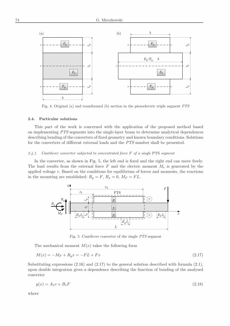
The averaging value of the moment of inertia Jo can be calculated using the method oftransformation of the cross sectional area (Fertis, 1996). Three materials of different stiffnessmoduli and the same width b (Fig. 4a) are replaced with one material of the section composedof three parts of different widths (Fig. 4b).The sought moment of inertia, calculated in relation to the neutral layer, is
Jo =bβ
12Ep(2.15)
where: β = Ebt3b + 2Eptp(3t
2b + 6tbtp + 4t
2p).
Substituting formula (2.13) with (2.11), (2.14) and (2.15) results in the electric bendingmoment value in function of the applied voltage v
Me = −bEpvβd31(tb + tp)
2α(2.16)
74 G. Mieczkowski
Fig. 4. Original (a) and transformed (b) section in the piezoelectric triple segment PTS
2.4. Particular solutions
This part of the work is concerned with the application of the proposed method basedon implementing PTS segments into the single-layer beam to determine analytical dependencesdescribing bending of the converters of fixed geometry and known boundary conditions. Solutionsfor the converters of different external loads and the PTS number shall be presented.
2.4.1. Cantilever converter subjected to concentrated force F of a single PTS segment
In the converter, as shown in Fig. 5, the left end is fixed and the right end can move freely.The load results from the external force F and the electric moment Me is generated by theapplied voltage v. Based on the conditions for equilibrium of forces and moments, the reactionsin the mounting are established: Ry = F , Rx = 0, MF = FL.
Fig. 5. Cantilever converter of the single PTS segment
The mechanical moment M(x) takes the following form
M(x) = −MF +Ryx = −FL+ Fx (2.17)
Substituting expressions (2.16) and (2.17) to the general solution described with formula (2.1),upon double integration gives a dependence describing the function of bending of the analysedconverter
y(x) = A1v +B1F (2.18)
where

The constituent equations of piezoelectric cantilevered three-layer actuators... 75
A1 =−3d31Ep(tb + tp)
α
(
H[x− x1](x− x1)2 −H[x− x2](x− x2)
2)
B1 =2
bβEbt3b
{
(β − Ebt3b)(
H[x− x1](3L− x− 2x1)(x− x1)2
−H[x− x2](3L− x− 2x2)(x− x2)2)
− βx2(3L− x)}
The integration constants are determined on the basis of the following boundary conditions
∂y
∂x(0) = 0 y(0) = 0 (2.19)
2.4.2. Cantilever converter subjected to concentrated force F of two PTS segments
For the converter shown in Fig. 6 the conditions of mounting and mechanical load are identicalas in the case described in Section 2.4.1. The electrical load is generated by two PTS segmentspowered by voltage v1 and v2.
Fig. 6. Cantilever converter of two PTS segments
The differential equation for deflection is as follows
∂2y
∂x2=M(x)
EbJb+Me1γ(H[x− x1]−H[x− x2]) +Me2γ(H[x− x3]−H[x− x4]) (2.20)
In the formula above, the mechanical moment M(x) is described by equation (2.17), while theelectrical moments are
Me = −bEpviβd31(tb + tp)
2αi = 1, 2 (2.21)
Solving differential equation (2.20) and assuming boundary conditions (2.19) gives the functiondescribing bending of the analysed converter
y(x) = A1v1 +A2v2 +B2F (2.22)
where
A2 =−3d31Ep(tb + tp)
α
(
H[x− x3](x− x3)2 −H[x− x4](x− x4)
2)
B2 =2
bβEbt3b
{
(β − Ebt3b)(
H[x− x1](3L− x− 2x1)(x− x1)2
−H[x− x2](3L− x− 2x2)(x− x2)2 +H[x− x3](3L − x− 2x3)(x− x3)
2
−H[x− x4](3L− x− 2x4)(x− x4)2)
− βx2(3L− x)}

76 G. Mieczkowski
2.4.3. Cantilever converter subjected to uniform external load p of the single PTS segment
In the actuator shown in Fig. 7, the conditions of mounting are identical as those describedin Sections 2.4.1 and 2.4.2. The converter is acted on by a uniform load p. The electrical momentis generated by a single PTS located at the left end.
Fig. 7. Cantilever converter of a single PTS segment
Based on the conditions for equilibrium of forces and moments, the reactions in the mountingare determined: Ry = p(L − x2), MF = 0.5p(L − x2)(L + x2). The mechanical moment M(x)takes the following form
M(x) = Ryx−MF −p(x− x2)
2
2H[x− x2] (2.23)
Solving differential equation (2.1), assuming mechanical (2.23) and electric (2.16) moments givesthe equation describing deflection of the analysed converter
y(x) = A3v +B3p (2.24)
where
A3 =−3d31Ep(tb + tp)
α
(
H[x]x2 −H[x− x1](x− x1)2)
B3 =1
2bβEbt3b
{
(β −Ebt3b)
·(
H[x− x1](H[x− x2](x− x2)4 + 2(x− x1)
2(L− x2)(3L− 2x+ 3x2))
−H[x](
H[x− x2](x− x2)4 + 2x2(L− x2)(3L − 2x+ 3x2)
))
+ β(
H[x− x2](x− x2)4 + 2x2(L− x2)(3L− 2x+ 3x2)
)}
Integration constants are determined on the basis of the following boundary conditions
∂y
∂x(0) = 0 y(0) = 0 (2.25)
2.5. Dynamical behavior of piezoelectric converters
As mentioned before, piezoelectric transducers similarly to other elastic bodies having mass,are prone to vibrations. In this respect, it is advised to include its oscillating nature of motionin the process of designing and exploitation of piezoelectric structures. Generally, vibrations canbe divided into two groups – free and forced. Free vibrations occur when external forces do notinfluence the body and the system vibrates due to action of inherent forces. In that case, the

The constituent equations of piezoelectric cantilevered three-layer actuators... 77
system is going to vibrate with one or more natural frequencies. In vibrating systems naturaldamping occurs caused by forces of the internal friction. Damping is usually slight, thus doesnot affect the natural frequencies.
In the case when vibrations are caused by external forces, there appear the so called forcedvibrations, and the system is going to vibrate with the excitation frequency.
The phenomenon of resonance is greatly dangerous for a structure. It occurs when the exci-tation frequency coincides with one of the natural frequencies which causes perilously highoscillations that may lead to damaging of the structure. Therefore, it is necessary to determinethe natural frequencies and geometrical and material factors affecting their distribution.
Upon elementary theory of bending beams, equation (1) can be presented in the followingway
∂2
∂x2
(
E(x)J(x)∂2y
∂x2
)
+ ρ(x)A(x)∂2y
∂t2=∂2M(x)
∂x2+Me(δ
′[x− x1]− δ′[x− x2]) (2.26)
where δ[x − xi], E(x), J(x), ρ(x), A(x) is the derivative of Dirac’s function, Young’s modulus,moment of inertia, density and cross sectional area of the converter. For free vibration, theexactly same differential equation can be written in the following way
∂2
∂x2
(
E(x)J(x)∂2y
∂x2
)
+ ρ(x)A(x)∂2y
∂t2= 0 (2.27)
The solution to equation (2.27) using the method of separation of variables can be written inthe following way
y(x, t) =W (x)T (t) (2.28)
whereW (x) is a function of space, and T (t) depends only on time. Substituting (2.28) with (2.27)and performing simple mathematical modifications, the commonly known differential equationdescribing the beam boundary problem is obtained
∂2
∂x2
(
E(x)J(x)∂2W
∂x2
)
− ρ(x)A(x)ω2 = 0 (2.29)
where ω is the natural frequency of vibration.
Let us consider the piezoelectric transducer shown in Fig. 8.
Fig. 8. Cantilever converter of n PTS segment
There can be n fragments distributed on the transducer whose total length is equal to∑ni=1 Lmi = L. Each and every fragment consists of three elements – a PTS segment and

78 G. Mieczkowski
two beam elements. Applying local frames of reference, using the dimensionless coordinates,differential equation (2.29) is equivalent to
∂4W1,i(ζ1,i)
∂ζ41,i− ψ4W1,i(ζ1,i) = 0 for ζ1,i ∈ 〈0, κi〉
∂4W2,i(ζ2,i)
∂ζ42,i− Λ4ψ4W2,i(ζ2,i) = 0 for ζ2,i ∈ 〈0, χi〉
∂4W3,i(ζ3,i)
∂ζ43,i− ψ4W3,i(ζ3,i) = 0 for ζ3,i ∈ 〈0,
LmiL− κi − χi〉
(2.30)
where
ψ4 = L4ω2ρbAbEbJb
Λ4 =EbJbρbAb
ρbAb + 2ρpApEpJo
ζ1,i =x
Lζ2,i =
x− κiL
Lζ3,i =
x− κiL− χiL
L
ζ1,i+1 =x− Lmi
Li = 1, . . . , n
ω is the natural frequency, ρb, ρp is density of beam and piezoelectric material, respectively.
Solutions to differential equations (2.30) can be obtained as (Mahmoud and Nassar, 2000)
W1,i(ζ1,i) = A1,i sin(ψζ1,i) +B1,i cos(ψζ1,i) + C1,i cosh(ψζ1,i) +D1,i sinh(ψζ1,i)
W2,i(ζ2,i) = A2,i sin(Λψζ2,i) +B2,i cos(Λψζ2,i) + C2,i cosh(Λψζ2,i) +D2,i sinh(Λψζ2,i)
W3,i(ζ3,i) = A3,i sin(ψζ3,i) +B3,i cos(ψζ3,i) + C3,i cosh(ψζ3,i) +D3,i sinh(ψζ3,i)
(2.31)
where Aj,i, Bj,i, Cj,i, Dj,i, j = 1, 2, 3 are constants.
The boundary conditions of mounting of the converter (left end is fix-mounted and the rightone freely move) together with continuity conditions at the intermediate ends lead to a set n×12linear homogeneous equations.
The continuity conditions adopt the following form
W1,i(ζ1,i)∣
∣
∣
ζ1,i=κi=W2,i(ζ2,i)
∣
∣
∣
ζ2,i=0
∂W1,i(ζ1,i)
∂ζ1,i
∣
∣
∣
∣
∣
ζ1,i=κi
=∂W2,i(ζ2,i)
∂ζ1,i
∣
∣
∣
∣
∣
ζ2,i=0
∂2W1,i(ζ1,i)
∂ζ21,i
∣
∣
∣
∣
∣
ζ1,i=κi
= η∂2W2,i(ζ2,i)
∂ζ22,i
∣
∣
∣
∣
∣
ζ2,i=0
∂3W1,i(ζ1,i)
∂ζ31,i
∣
∣
∣
∣
∣
ζ1,i=κi
= η∂3W2,i(ζ2,i)
∂ζ32,i
∣
∣
∣
∣
∣
ζ2,i=0
W2,i(ζ2,i)∣
∣
∣
ζ2,i=χi=W3,i(ζ3,i)
∣
∣
∣
ζ3,i=0
∂W2,i(ζ2,i)
∂ζ2,i
∣
∣
∣
∣
∣
ζ2,i=χi
=∂W3,i(ζ3,i)
∂ζ3,i
∣
∣
∣
∣
∣
ζ3,i=0
η∂2W2,i(ζ2,i)
∂ζ22,i
∣
∣
∣
∣
∣
ζ2,i=χi
=∂2W3,i(ζ3,i)
∂ζ23,i
∣
∣
∣
∣
∣
ζ3,i=0
η∂3W2,i(ζ2,i)
∂ζ32,i
∣
∣
∣
∣
∣
ζ2,i=χi
=∂3W3,i(ζ3,i)
∂ζ33,i
∣
∣
∣
∣
∣
ζ3,i=0
(2.32)

The constituent equations of piezoelectric cantilevered three-layer actuators... 79
W3,i(ζ3,i)∣
∣
∣
ζ3,i=φi=W1,i+1(ζ1,i+1)
∣
∣
∣
ζ1,i+1=0
∂W3,i(ζ3,i)
∂ζ3,i
∣
∣
∣
∣
∣
ζ3,i=φi
=∂W1,i+1(ζ1,i+1)
∂ζ1,i+1
∣
∣
∣
∣
∣
ζ1,i+1=0
∂2W3,i(ζ3,i)
∂ζ23,i
∣
∣
∣
∣
∣
ζ3,i=φi
=∂2W1,i+1(ζ1,i+1)
∂ζ21,i+1
∣
∣
∣
∣
∣
ζ1,i+1=0
∂3W3,i(ζ3,i)
∂ζ33,i
∣
∣
∣
∣
∣
ζ3,i=φi
=∂3W1,i+1(ζ1,i+1)
∂ζ31,i+1
∣
∣
∣
∣
∣
ζ1,i+1=0
where
η =EpJoEbJb
φi =LmiL− κi − χi
The boundary conditions can be written as follows:— fixed
W1,1(ζ1,1) = 0∣
∣
∣
ζ1,1=0
∂W1,1(ζ1,1)
∂ζ1,1= 0
∣
∣
∣
∣
∣
ζ1,1=0
(2.33)
— free
EbJb∂2W3,n(ζ3,n)
∂ζ23,n= 0
∣
∣
∣
∣
∣
ζ3,n=LmnL−κn−χn
EbJb∂3W3,n(ζ3,n)
∂ζ33,n= 0
∣
∣
∣
∣
∣
ζ3,n=LmnL−κn−χn
(2.34)
Using dependences (2.31)-(2.34), as mentioned before, n × 12 linear homogenous equation canbe achieved.The values of dimensionless frequencies ψ are determined from the characteristic equation
representing the zero determinant of the matrix of boundary conditions M12n×12n
M12n×12n =
M12×12i B12×12 · · · 012×12
C12×12i M12×12i+1 · · · 012×12
......
. . . B12×12
012×12 012×12 C12×12n−1 M12×12n
(2.35)
where 012×12 is the zero matrix, M12×12i =[
M12×41,i M12×42,i M12×42,i
]
, the remaining matrices
are shown in Appendix. For the transducer with one segment, matrix (2.35) simplifies to thefollowing form
M12×12 =[
M12×41,1 M12×42,1 M12×42,1
]
(2.36)
An analytical form of the characteristic equation (|M12nx12n| = 0) in special cases where∑ni=1 χi = 0 (homogenous beam) and
∑ni=1 χi = 1 (PTS segment all along) is described from
subsequent equations
1 + cosψ coshψ = 0 1 + cos(Λψ) cosh(Λψ) = 0 (2.37)
In other cases, in order to determine ψ, the roots of the characteristic equation can be obtainedusing numerical methods. In Figs. 9 and 10, there are dimensionless frequencies ψ presented infunction of length of the piezoelectric layer for different locations and amount of PTS segments.The results achieved for the transducer with one PTS segment (Lm1 = L) are shown in Fig. 9,whereas for the transducer with two PTS segments (Lm1 + Lm2 = L, Lm1 = Lm2) are shownin Fig. 10. Furthermore, three variants of piezoelectric segment locations in the transducer havebeen examined. Namely:

80 G. Mieczkowski
• PTS segment located on the left end (κi = 0),
• transducer with PTS segment located in the middle (κi + 0.5χi = 0.25),
• PTS segment located on the right end (κi + χi = 1).
Moreover, in the transducer with two piezoelectric segments there are identical geometric andmaterial features adopted for both PTS segments.
Fig. 9. The dimensionless frequencies ψ for the converter eith a single PTS segment, ψ1 – firstfrequency, ψ2 – second frequency
Fig. 10. The dimensionless frequencies ψ for the converter with a double PTS segment, ψ1 – firstfrequency, ψ2 – second frequency

The constituent equations of piezoelectric cantilevered three-layer actuators... 81
Analyzing the obtained results, it can be stated that the highest values of the first dimension-less frequency, independent from PTS length, is acquired for the piezoelectric segment placed onthe left end (Figs. 9 and 10). Similarly is with the second frequency for the converter with twosegments. For the converter with one segment, the second frequency, depending on PTS length,takes the highest values for the converter with the segment placed either on the left end, or inthe middle.
The dimensionless frequencies ψ depend on the relative stiffness η and the unit weightµ = (ρbAb+2ρpAp)/(ρbAb) of the beam and the PTS segment. In Figs. 11a and 11b, the influenceof η and µ on the ψ value. Upon the received results, it can be stated that the dimensionlessfrequencies decrease with an increase in the parameters η (Fig. 11a) and µ (Fig. 11b).
Fig. 11. The impact of relative stiffness (a) and relative unit (b) on the dimensionless frequency ψ forthe converter with a single PTS segment, ψ1 – first frequency, ψ2 – second frequency
The circular frequency ω [Hz] of the transducer can be calculated from formula
ω =ψ2
2π
√
EbJbρbAbL4
(2.38)
3. Numerical calculations
To confirm the correctness of the obtained analytical solutions (static deflection of the trans-ducer and circular frequencies), it is necessary to perform numerical analyses. FEM simulationshave been prepared and compared with the obtained analytical results. Numerical tests aimedat determining the bending line and circular frequencies of the actuators for arbitrarily assu-med material constants and geometry. The tested converters, shown in Figs. 5-7, have beenmodelled using the FEM with the help of ANSYS (Mieszczak et al., 2006; Documentation forANSYS, 2010). Plane components hve been described using a grid of quadrangular, eight-nodefinite elements, with increased concentration at critical points such as sharp corners, mountingpoints and places at which the mechanical load was applied. For the piezoelectric component,PLANE223 type elements have been applied, and non-piezoelectric material has been meshedwith PLANE183 elements with steel material properties. In view of the fact that the actuatorsare usually made of piezoelectric ceramics, PZ26 has been used as a material of the piezoelectriccomponent. The size of finite elements was tp/4. The plane issue has been solved for plane strainconditions.
In the calculations, the following geometrical and material data has been assumed: Young’smodulus Ep = 7.7 · 10
10 N/m2, Eb = 2.0 · 1011 N/m2; Poisson’s ratio νp = 0.3, νb = 0.33; density
ρp = 7700 kg/m3, ρb = 7860 kg/m
3; piezoelectric strain coefficients d31 = −1.28 · 10−10m/V,

82 G. Mieczkowski
d33 = 3.28 · 10−10m/V, d15 = 3.27 · 10
−10m/V; beam length L = 60mm; layers thicknesstp = 0.5mm, tb = 1mm. The values of applied load are: electrode voltage v = 100V; forceF = 100N; uniform external load p = 100N/m. Coordinates xi, χi (Figs. 5-8), defining the PTSand external loads application positions are given in Section 4.
4. Results of tests
In this part of the work, the deflection line of converters for which the resulting special solutionsare given in Section 2.4 are graphically presented. The results obtained from the analyticalsolutions have been compared with FEM solutions. In the analytical equations, the materialand geometrical data are identical as the data given in Section 3 was applied.
A comparison of analytical solution (2.18) with FEM for the cantilever converter of the singlePTS segment (Fig. 5) is shown in Fig. 12.
Fig. 12. Deflection of the cantilever converter with a single PTS segment for x1 = 1/12L, x2 = 5/12L:(a) subjected only to electrical voltage, v = 100V, F = 0; (b) subjected only to force, v = 0V,
F = 100N
Figure 13 shows the deflection of the cantilever converter of double PTS segments (Fig. 6),for which the analytical solution is described by formula (2.22).
Fig. 13. Deflection of the cantilever converter with double PTS segments for x1 = 1/12L, x2 = 5/12L,x3 = 7/12L, x4 = 11/12L: (a) subjected only to electrical voltage, v1 = 100V, v2 = 150V, F = 0;
(b) subjected only to force, v1 = v2 = 0, F = 100N
Figure 14 shows the strain of the cantilever converter subjected to a uniform external load pof the single PTS segment (Fig. 7) for which the analytical solution is described by formula(2.24).
Basing on the obtained results of static deflections of the converters, the qualitative andquantitative compliance of analytical and numerical solutions can be stated. Generally, thedifference between the analytical and numerical solutions is approx. 1% for the electrical load,and 2-3% for the mechanical load.

The constituent equations of piezoelectric cantilevered three-layer actuators... 83
Fig. 14. Deflection of the cantilever converter subjected to a uniform external load p for x1 = 1/3L,x2 = 2/3L: (a) subjected only to electrical voltage, v = −100V, p = 0; (b) subjected only to uniform
external load, v = 0V, p = 100N/m
By means of FEM, it has been helpful to determine circular frequencies of the transducerswith one (Fig. 7) and two (Fig. 6) PTS segments. The material and geometric data has beenadopted identically as in the above-described static analysis. The obtained results (Table 1) havebeen compared to the analytical solution (formula (2.38) and Figs. 9 and 10).
Table 1. Comparison of the first two frequencies between the analytical and FEM results
Modesequence ω∗ [Hz] ω∗∗ [Hz] Error [%] ω∗ [Hz] ω∗∗ [Hz] Error [%]
1 368.5 379.4 2.9 252.1 256.4 1.7
2 1799.8 1837.7 2.1 1575.4 1543.8 2∗ – analytical solution, ∗∗ – FEM solution
In the dynamical analysis as well as in the static analysis, a satisfactory compatibility ofboth obtained solutions has been indicated. The disparity in these results ranges less than 3%.
5. Summary and conclusions
The paper deals with the issue of bending of three-layer piezoelectric actuators subjected toelectric field and mechanical load. A general solution has been developed, based on the im-plementation of piezoelectric segments PTS to a homogeneous (one-layer) beam. The workingmechanism and conditions for strain of the PTS segment have been determined. Basing on thegeneral solution, for arbitrarily selected three different types of converters, special solutions ha-ve been developed (for the cantilever actuator of single and double PTS segments subjectedto external force and the converter with a single PTS acted on by a uniform external load).Moreover, dynamical analysis of transducers has been performed. Also, a matrix whose deter-minant enables determination of the characteristic equation for the transducer with any amountof piezoelectric segments has been formulated. On the basis of characteristic equations, for theconverter with one and two PTS, the natural frequencies and the influence of relative stiffness,size and placing of a segment on their value have been determined. The obtained analyticalsolutions have been compared with the developed FEM solution.On the basis of the performed analytical and numerical tests, it is found that:
• the developed method involving the implementation of PTS segments into a homogeneousbeam allows obtaining solutions for piezoelectric converters:
– of any either type of the external load,

84 G. Mieczkowski
– of diverse lengths and heights of piezoelectric and non-piezoelectric layers,
– with any number of piezoelectric components;
• the obtained particular solutions allows determination of the deflection at any point of theconverter;
• the maximum values of the first dimensionless frequency, independently of the length andnumber of PTS, are to be obtained for segments with mountings located closer;
• for a transducer with two PTS segments, the distribution of the second frequency is thesame as for the first frequency;
• for a transducer with one piezoelectric segment, the second frequency depending on PTSlength holds the highest value for either the converter with the segment located on the leftend or for the one with the segment located in the middle;
• the dimensionless frequencies decrease with an increase in the relative stiffness and unitmass of the piezoelectric segment;
• the particular solutions of static behaviour confirm with the results obtained from FEM(for the electrical load the maximum difference is approx. 1%, and for the mechanical load– approx. 3%);
• a similar discrepancy between the analytical solution and FEM (less than 3%) has beenobtained while calculating circular frequencies.
Appendix
M12×41,i =
0 1 1 0ψ 0 0 ψ
sin(ψκi) cos(ψκi) cosh(ψκi) sinh(ψκi)ψ cos(ψκi) −ψ sin(ψκi) ψ sinh(ψκi) ψ cosh(ψκi)−ψ2 sin(ψκi) −ψ
2 cos(ψκi) ψ2 cosh(ψκi) ψ2 sinh(ψκi)−ψ3 cos(ψκi) ψ3 sin(ψκi) ψ3 sinh(ψκi) ψ3 cosh(ψκi)
0 0 0 0...
......
...0 0 0 0
M12×42,i =
0 0 0 00 0 0 00 −1 −1 0−Λψ 0 0 −Λψ0 ηΛ2ψ2 −ηΛ2ψ2 0
ηΛ3ψ3 0 0 −ηΛ3ψ3
− sin(Λψχi) − cos(Λψχi) − cosh(Λψχi) − sinh(Λψχi)−Λψ cos(Λψχi) Λψ sin(Λψχi) −Λψ sinh(Λψχi) −Λψ cosh(Λψχi)ηΛ2ψ2 sin(Λψχi) ηΛ2ψ2 cos(Λψχi) −ηΛ
2ψ2 cosh(Λψχi) −ηΛ2ψ2 sinh(Λψχi)
ηΛ3ψ3 cos(Λψχi) −ηΛ3ψ3 sin(Λψχi) −ηΛ
3ψ3 sinh(Λψχi) −ηΛ3ψ3 cosh(Λψχi)
0 0 0 00 0 0 0

The constituent equations of piezoelectric cantilevered three-layer actuators... 85
M12×43,i =
0 0 0 0...
......
...0 1 1 0ψ 0 0 ψ0 −ψ2 ψ2 0−ψ3 0 0 ψ3
−ψ2 sin(ψφi) −ψ2 cos(ψφi) ψ2 cosh(ψφi) ψ2 sinh(ψφi)
−ψ3 cos(ψφi) ψ3 sin(ψφi) ψ3 sinh(ψφi) ψ3 cosh(ψφi)
B12×12=
0 0 0 0 0 · · · · · · 0......
......... · · · · · ·
...0 ψ2 −ψ2 0 0 . . 0ψ3 0 0 −ψ3 0 . . 0
C12×12i =
0 · · · − sin(ψφi) − cos(ψφi) − cosh(ψφi) − sinh(ψφi)0 · · · −ψ cos(ψφi) ψ sin(ψφi) −ψ sinh(ψφi) −ψ cosh(ψφi).... . .
......
......
0 · · · 0 0 0 0
References
1. Askari Farsangi M.A., Saidi A.R., Batra R.C., 2013, Analytical solution for free vibrationsof moderately thick hybrid piezoelectric laminated plates, Journal of Sound and Vibration, 332,5981-5998
2. Berlincourt D.A., Curran D.R., Jaffe H., Mason W.P., 1964, Physical Acoustics, Princi-ples and Methods, Academic Press, New York
3. Bleustein J.L., Tiersten H.F., 1968, Forced thickness-shear vibrations of discontinuously pla-ted piezoelectric plates, Journal of the Acoustical Society of America, 43, 6, 1311
4. Buchacz A., Płaczek M., 2009, Damping of mechanical vibrations using piezoelements, inclu-ding influence of connection layer’s properties, on the dynamic characteristic, Solid State Pheno-mena, 147/149, 869-875
5. Busch-Vishniac I.J., 1999, Electromechanical Sensors and Actuators, Springer-Verlag
6. Chen W.Q., Xu R.Q., Ding H.J., 1998, On free vibration of a piezoelectric composite rectangularplate, Journal of Sound and Vibration, 218, 4, 741-748
7. Clarc R.L., Fuller Ch.R., Wicks A., 1991, Characterization of multiple piezoelectric actuatorsfor structural excitation, Journal of Acoustical Society of America, 90, 346-357
8. Curie P.J., Curie J., 1880, Crystal physics-development by pressure 0/ polar electricity in he-mihedral crystals with inclined faces (in French), Comptes rendus hebdomadaires des sances del’Acadmie des sciences, 294, pp. 91
9. Djojodihardjo H., Jafari M., Wiriadidjaja S., Ahmad K.A., 2015, Active vibration sup-pression of an elastic piezoelectric sensor and actuator fitted cantilevered beam configurations asa generic smart composite structure, Composite Structures, 132, 848-863
10. Documentation for ANSYS, 2010, Coupled-Field Analysis Guide
11. Fertis D.G., 1996, Advanced Mechanics of Structures, Marcel Dekker, New York
12. Kawai H., 1969, The piezoelectricity of poly (vinylidene fluoride), Japanese Journal of AppliedPhysics, 8, 975
13. Liu X., Wang X., Zhao H., Du Y., 2014, Myocardial cell pattern on piezoelectric nanofibermats for energy harvesting, Journal of Physics: Conference Series, 557, 012057

86 G. Mieczkowski
14. Mahmoud A.A., Nassar M.A., Free vibration of a stepped beam with two uniform and/ortapered parts, Mechanics and Mechanical Engineering, 4, 2, 165-181
15. Mieczkowski G., 2016, Electromechanical characteristics of piezoelectric converters with freelydefined boundary conditions and geometry, Mechanika, 22, 4, 265-272
16. Mieszczak Z., Krawczuk M., Ostachowicz W., 2006, Interaction of point defects in piezo-electric materials – numerical simulation in the context of electric fatigue, Journal of Theoreticaland Applied Mechanics, 44, 4, 650-665
17. Park J.K., Moon W.K., 2005, Constitutive relations for piezoelectric benders under variousboundary conditions, Sensors and Actuators A, 117, 159-167
18. Pietrzakowski M., 2000, Multiple piezoceramic segments in structural vibration control, Journalof Theoretical and Applied Mechanics, 38, 378-393
19. Pietrzakowski M., 2001, Active damping of beams by piezoelectric system: effects of bondinglayer properties, International Journal of Solids and Structures, 38, 7885-7897
20. Przybyłowicz P.M., 1999, Application of piezoelectric elements to semi-adaptive dynamic ele-minator of torsional vibration, Journal of Theoretical and Applied Mechanics, 37, 2, 319-334
21. Raeisifard H., Bahrami M.N., Yousefi-Koma A., Fard H.R., 2014, Static characteriza-tion and pull-in voltage of a micro-switch under both electrostatic and piezoelectric excitations,European Journal of Mechanics A/Solids, 44, 116-124
22. Rahmoune M., Osmont D., 2010, Classic finite elements for simulation of piezoelectric smartstructures, Mechanika, 86, 6, 50-57
23. Rajabi A.H., Jaffe M., Arinzeh T.J., 2015, Piezoelectric materials for tissue regeneration: Areview, Review Article, Acta Biomaterialia, 24, 15, 12-23
24. Rouzegar J., Abad F., 2015, Free vibration analysis of FG plate with piezoelectric layers usingfour-variable refined plate theory, Thin-Walled Structures, 89, 76-83
25. Smits J.G., Dalke S.I., Cooney T.K., 1991, The constituent equations of piezoelectric bimor-phs, Sensors and Actuators A, 28, 41-61
26. Stefanescu D.M. 2011, Piezoelectric Force Transducers (PZFTs), [In:] Handbook of Force Trans-ducers, 109-130
27. Tylikowski A., 1993, Stabilization of beam parametric vibrations, Jurnal of Theoretical andApplied Mechanics, 31, 3, 657-670
28. Tzou H.S., 1999, Piezoelectric Shells: Distributed Sensing and Control of Continua, Kluwer Aca-demic Publishers, Dordrecht
29. Wang Q., Cross L.E., 1999, Constitutive equations of symmetrical triple-layer piezoelec-tric benders, IEEE Transactions on Ultrasonics, Ferroelectronics, and Frequency Control, 46,1343-1351
30. Xiang H.J., Shi Z.F., 2008, Static analysis for multi-layered piezoelectric cantilevers, Internatio-nal Journal of Solids and Structures, 45, 1, 113-128
Manuscript received October 6, 2015; accepted for print May 6, 2016