applied wireless electronics grzegorz budzy„ lecture 4
TRANSCRIPT
AppliedApplied WirelessWireless ElectronicsElectronics
Grzegorz BudzyGrzegorz Budzyńń
LLectureecture 44::IntroductionIntroduction to to antennaantenna terminologyterminologyWireless data transfer Wireless data transfer –– BluetoothBluetooth
Plan
• Bluetooth
– Bluetooth protocol stack
– Application examples
• NFC

Introduction

Bluetooth History
• Began as a private development effort atEricsson in 1994
• 5 companies joined to form the Bluetooth Special Interest Group (SIG) in 1998
• First specification released in July 1999
• Current specification is version 4.0

Bluetooth Goals
• Open Specification
• Voice and Data Capability
• Worldwide Usability
• Short-Range Wireless Solutions

Bluetooth Applications
• Cable Replacement– PCs & peripherals, home networking, headsets
• Ad-hoc Networking– Business card exchange, multi-player games,
vending machines, white goods, etc.
• Data and Voice Access Points– E-mail, web access, cordless telephone, etc.
• Industrial– Inventory management systems

Bluetooth – its place

Bluetooth – Main features
• Destinied for operation in 2.4GHz range
• Maximum data rate – 732 kb/s (for 1.1 version)
• Medium access method: TDMA, controlled by host
• Modulation: GFSK (upto 1Mb/s), 4PSK (upto2Mb/s) or 8DPSK(upto 3Mb/s)
• 1 MHz channel spacing, with frequency hopping
• Adaptive Frequency Hopping, for co-existence
with Wi-Fi, etc

Bluetooth – Main features
• Only a few devices possible in the network
• Devices make a piconet and one host and upto 7 slave devices
• Bluetooth specification includes protocolsand profiles
• There are defined 3 output power classes for 1, 10 and 100 meter ranges

Bluetooth – Main features• Bluetooth is packet-based protocol
• Bluetooth is master-slave type protocol
• One master may communicate upto 7 devices(piconet)
• Packet exchange is based on the basic clock, defined by the master, which ticks at 312.5 µs intervals
• In the simple case of single-slot packets the master transmits in even slots and receives in odd slots

Bluetooth – Main features
• Packets may be 1, 3 or 5 slots long but in all cases the master transmit will begin in even slots and the slave transmits in odd slots

Bluetooth versions

Bluetooth versions• Bluetooth 1.0:
– Versions with many interoperability problems
• Bluetooth 1.1:– Ratified as a standard: IEEE802.15.1-2002
– Added Received Signal Strength Indicator (RSSI)
• Bluetooth 1.2:– Faster Connection and Discovery
– Adaptive frequency-hopping spread spectrum (AFH)
– Higher transmission speeds in practice, up to 721 kbit/s than in v1.1.
Bluetooth versions– Extended Synchronous Connections (eSCO),
which improve voice quality of audio links by allowing retransmissions of corrupted packets, and may optionally increase audio latency to provide better support for concurrent data transfer.
– Host Controller Interface (HCI) support for three-wire UART
– Ratified as IEEE Standard 802.15.1-2005
– Introduced Flow Control and Retransmission Modes for L2CAP
Bluetooth versions• Bluetooth 2.0+EDR:
– introduction of an Enhanced Data Rate (EDR) for faster data transfer
– The nominal rate of EDR is about 3 Mbit/s, the practical data transfer rate is 2.1 Mbit/s
• Bluetooth 3.0+HS:– Adopted in 2009
– supports theoretical data transfer speeds of up to 24 Mbit/s (BT only establishes connection, transmission goes over WiFi)

Bluetooth versions– The main new feature is AMP (Alternate
MAC/PHY), the addition of 802.11 as a high speed transport (+HS)
– Unicast Connectionless Data - Permits service data to be sent without establishing an explicit L2CAP channel. It is intended for use by applications that require low latency between user action and reconnection/transmission of data. This is only appropriate for small amounts of data
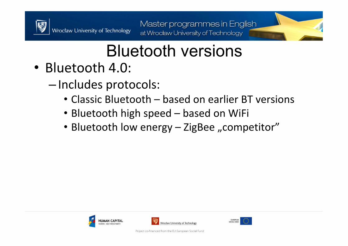
Bluetooth versions• Bluetooth 4.0:
– Includes protocols:• Classic Bluetooth – based on earlier BT versions
• Bluetooth high speed – based on WiFi
• Bluetooth low energy – ZigBee „competitor”
Bluetooth – energy consumption
• Bluetooth is connection oriented. When a device is
connected, a link is maintained, even if there is no
data flowing
• Sniff modes allow devices to sleep, reducing
power consumption to give months of battery life
• Peak transmit current is typically around 25mA
• For lowest power consumption there is BLE
(Bluetooth Low Energy) – subset of BT4.0

Bluetooth – Data rates

Bluetooth – Profiles
• Generic Access Profile
• Service Discovery Application Profile
• Serial Port Profile– Virtual COM port
– Dial-up Networking Profile
– FAX Profile
– LAN Access Profile
– Headset Profile

Bluetooth – Profiles
• Generic Object Exchange Profile– Object Push Profile
– File Transfer Profile
– Synchronization Profile
• TCS– Cordless Telephony Profile
– Intercom Profile

Important Bluetooth strengths• Interoperability
– Between manufacturers
– Between types of devices
• Ease of Use– No user’s guide
– Self-descriptive interface
• Low Price– Same or less than the cable it is replacing
• Low Power Consumption– No/little additional charging

Bluetooth Power Classes
Bluetooth Power Classes
• Bluetooth devices operate in three powerclasses:– Class I, upto 100mW (20dBm) and 100m range
– Class II, upto 2.5mW (4dBm) and 10m range
– Class III, upto 1mW (0dBm) and 1m range

Bluetooth Protocol Stack

Bluetooth Protocol Stack
Sourc
e: [1
]
Transport Protocol Group
RF
Baseband
AudioLink Manager
L2CAP
Data
SDP RFCOMM
IP
Control
Applications
Transport Protocol Group
Sourc
e: [2
]
Transport Protocol Group
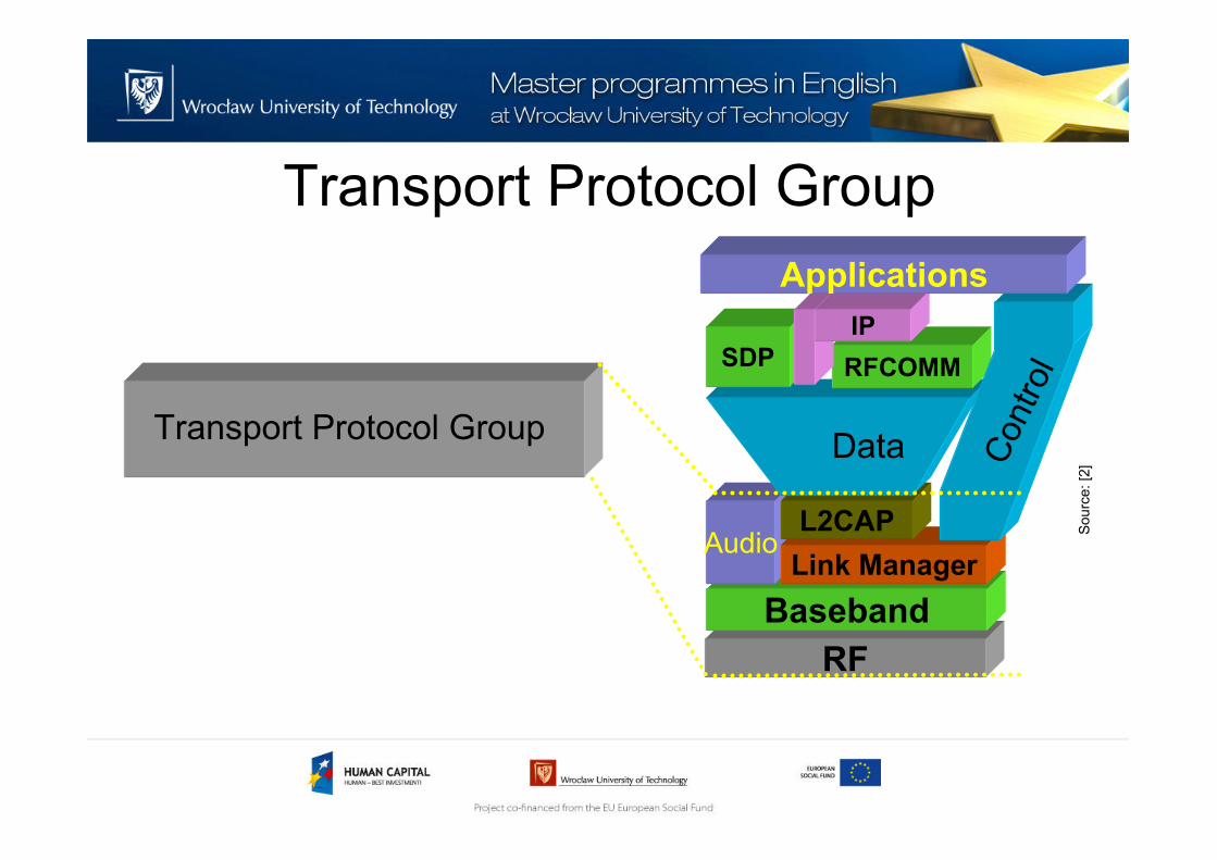
• Transport Protocol Group is composed of protocols to allow Bluetooth devices:– to locate each other
– to create,
– configure
– manage both physical and logical links that allow higher layer protocols and applications to pass data through these transport protocols
Transport Protocol Group• Radio Frequency (RF)
– Sending and receiving modulated bit streams
– Baseband
– Defines the timing, framing
– Flow control on the link.
• Link Manager – Managing the connection states.
– Enforcing Fairness among slaves.
– Power Management
Transport Protocol Group
• Logical Link Control &Adaptation Protocol– Handles multiplexing of higher level protocols
– Segmentation & reassembly of large packets
– Device discovery & QoS
– In Basic mode, L2CAP provides packets with a payload configurable up to 64 kB, with 672 bytes as the default MTU, and 48 bytes as the minimum mandatory supported MTU

Transport Protocol Group• Logical Link Control &Adaptation Protocol
– In Retransmission and Flow Control modes, L2CAP can be configured either for isochronous data or reliable data per channel by performing retransmissions and CRC checks
– Enhanced Retransmission Mode (ERTM) is an improved version of the original retransmission mode (reliable)
– Streaming Mode (SM) is a very simple mode, with no retransmission or flow control(unreliable)

Middleware Protocol Group
RF
Baseband
AudioLink Manager
L2CAP
Data
SDP RFCOMM
IP
Control
Applications
Middleware Protocol Group
Sourc
e: [2
]

Middleware Protocol Group
• Middleware Protocol Group is additionaltransport protocols to allow existing and new applications to operate over Bluetooth.
• Packet based telephony control signaling protocol also present.
• Also includes Service Discovery Protocol
Middleware Protocol Group
• Service Discovery Protocol (SDP)– Allows a device to discover services offered by
other devices, and their associated parameters
– Each service is identified by a UUID (UniversallyUnique ID) with official services (Bluetooth profiles) assigned a short form UUID (16b instead of 128)
• TCP/IP– Network Protocols for packet data
communication, routing
Middleware Protocol Group
• RFCOMM– Cable replacement protocol,
– Emulation of serial ports (RS-232) over wirelessnetwork
– Provides a simple reliable data stream to the user, similar to TCP
– Many Bluetooth applications use RFCOMM because of its widespread support and publicly available API on most operating systems

Application Group
RF
Baseband
AudioLink Manager
L2CAP
Data
SDP RFCOMM
IP
Control
ApplicationsApplication Group
• Consists of Bluetoothaware or unawaredevices
Sourc
e: [2
]

Bluetooth Network Details

Bluetooth Network Types• Point to Point Link
– Master - slave relationship
– Bluetooth devices can function as masters or slaves
• Piconet– It is the network formed by a Master and one
or more slaves (max 7).
– Each piconet is defined by a different hopping channel to which users synchronize to.
– Each piconet has max capacity (1 Mbps).
– Hopping pattern is determined by the master.

Piconet Structure
Master
Active Slave
Parked Slave
Standby
Sourc
e: [2
]

Packet Structure
72 bits 54 bits 0 - 2744 bits
DataVoice CRC
No CRC
No retries
header
ARQ
FEC (optional) FEC (optional)
Access
Code
Header Payload
Sourc
e: [2
]
Setting up connection
Connection states
• During the connection state, the bluetoothunits can be in several modes of operation:– Active mode
– Sniff mode
– Hold mode
– Park mode

Connection State Machine
Standby
Inquiry Page
Connected
Transmit data
Park Hold Sniff
Sourc
e: [2
]
Connection states
• Active mode– In the active mode, the Bluetooth unit actively
participates on the channel.
• Sniff mode– In the sniff mode, the duty cycle of the slave’s listen
activity can be reduced.
– With the sniff mode, the time slots where the master can start transmission to a specific slave is reduced; that is, the master can only start transmission inspecified time slots.

Connection states
• Hold mode (1/2)– The hold mode is typically entered when there
is no need to send data for a relatively long time.
– Thus, the unit in hold mode enter a low-power sleep mode.
– In Addition, with the hold mode, capacity can be made free to do other things like scanning, paging, inquiring, or attending another piconet

Connection states
• Hold mode (2/2)– During the hold mode, the slave unit keeps its
active member address (AM_ADDR).
– Prior to entering the hold mode, master and slave agree on the time duration the slave remains in the hold mode.

Connection states
• Park mode (1/3)– When a slave does not need to participate on
the piconet channel, it can enter the park mode which is a low-power mode with very little activity in the slave.
– In the park mode, the slave gives up its active member address AM_ADDR. Instead, it receives two new addresses to be used in the park mode:• PM_ADDR: 8-bit Parked Member Address
• AR_ADDR: 8-bit Access Request Address

Connection states
• Park mode (2/3)– The PM_ADDR distinguishes a parked slave
from the other parked slaves. This address is used in the master-initiated unpark procedure.
– The AR_ADDR is used by the slave in the slave-initiated unpark procedure.
– All messages sent to the parked slaves have to be carried by broadcast packets because of the missing AM_ADDR.

Connection states
• Park mode (3/3)– To support parked slaves, the master
established a beacon channel when one or more slaves are parked.
– The beacon channel serves four purposes:• 1. transmission of master-to-slave packets which
the parked slaves can use for re-synchronization;
• 2. carrying messages to the parked slaves to change the beacon parameters;
• 3. carrying general broadcast messages to the parked slaves;
• 4. unparking of one or more parked slaves.

Setting up connection
• Any Bluetooth device in discoverable mode will transmit the following information on demand:
– Device name
– Device class
– List of services
– Technical information (for example: device features,
manufacturer, Bluetooth specification used, clock
offset)

Setting up connection• Any device may perform an inquiry to find other
devices to connect to, and any device can be configured to respond to such inquiries
• Use of a device's services may require pairing or acceptance by its owner, but the connection itself can be initiated by any device and held until it goes out of range
• Some devices can be connected to only one device at a time, and connecting to them prevents them from connecting to other devices and appearing in inquiries until they disconnect from the other device
Setting up connection• Every device has a unique 48-bit address
• These addresses are generally not shown in inquiries. Instead, friendly Bluetooth names (set by user) are used
• This name appears when another user scans for devices and in lists of paired devices

Frequency Hopping
Sourc
e: [1
]

Frequency Hopping
• Bluetooth channel is represented by a pseudo random hopping sequence through the entire 79 RF frequencies
• Nominal hop rate of 1600 hops per second
• Channel Spacing is 1 MHz
Time Division Duplex
• Bluetooth devices use a Time-Division Duplex (TDD) scheme
• Channel is divided into consecutive slots (each 625 µs)
• One packet can be transmitted per slot
• Subsequent slots are alternatively used for transmitting and receiving
– Strict alternation of slots between the master and the slaves
– Master can send packets to a slave only in EVEN slots
– Slave can send packets to the master only in the ODD slots

Bluetooth vs ZigBee

ZigBee vs standard Bluetooth

ZigBee vs BLE
• ZigBee is older. It has gone through some
iterations
• ZigBee has market share but a Market barrier:
ZigBee is not in PCs or mobile phones yet.
• Zigbee is low power; Bluetooth LE is even lower.
• ZigBee stack is light; the Bluetooth LE/GATT stack
is even simpler.
• ZigBee has a lead on developing applications and
presence

Example Applications
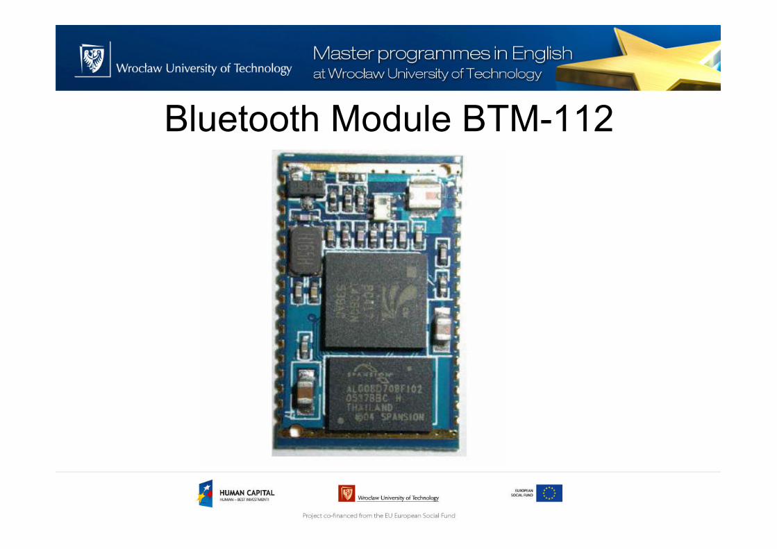
Bluetooth Module BTM-112
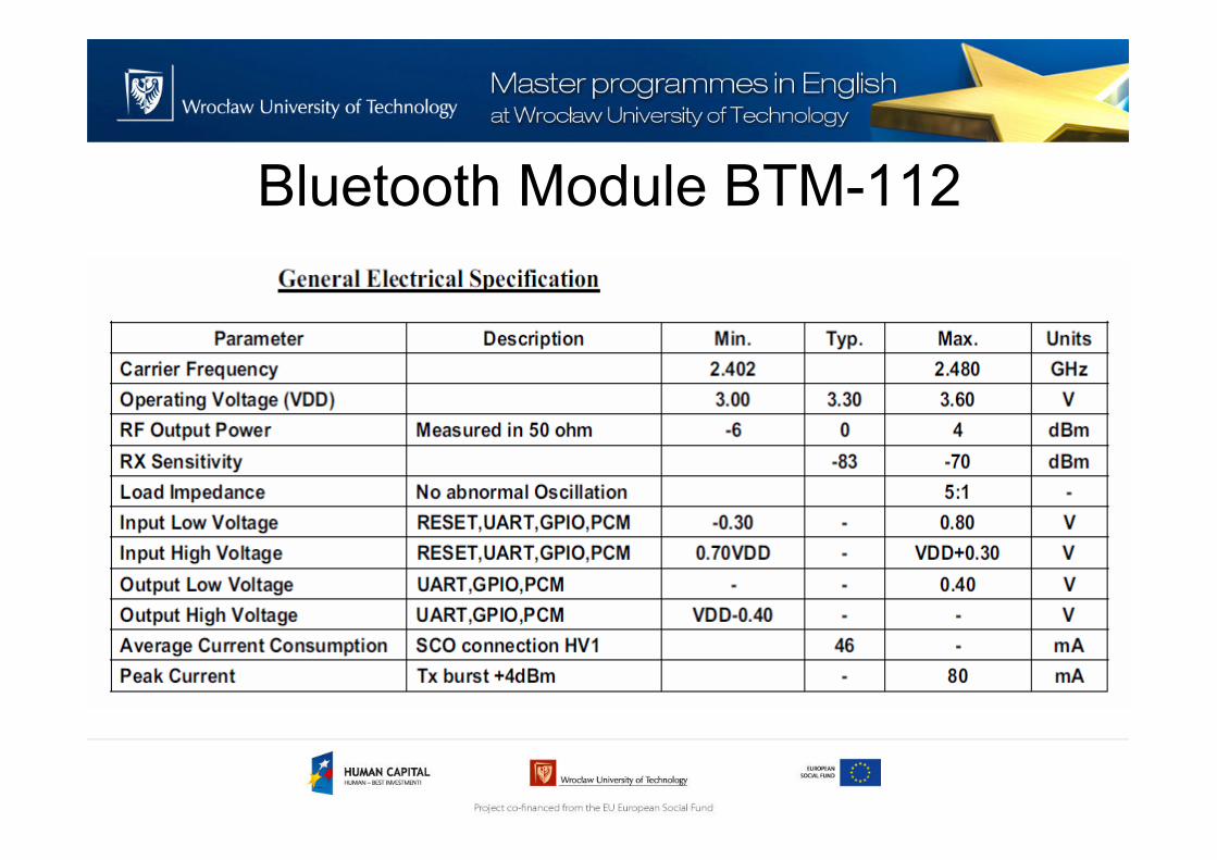
Bluetooth Module BTM-112
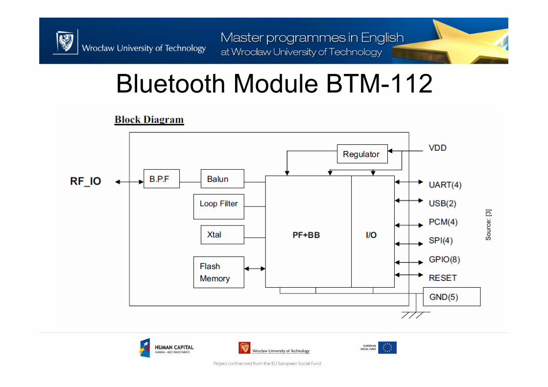
Bluetooth Module BTM-112
Sourc
e: [3
]
BLE SoC CC2541
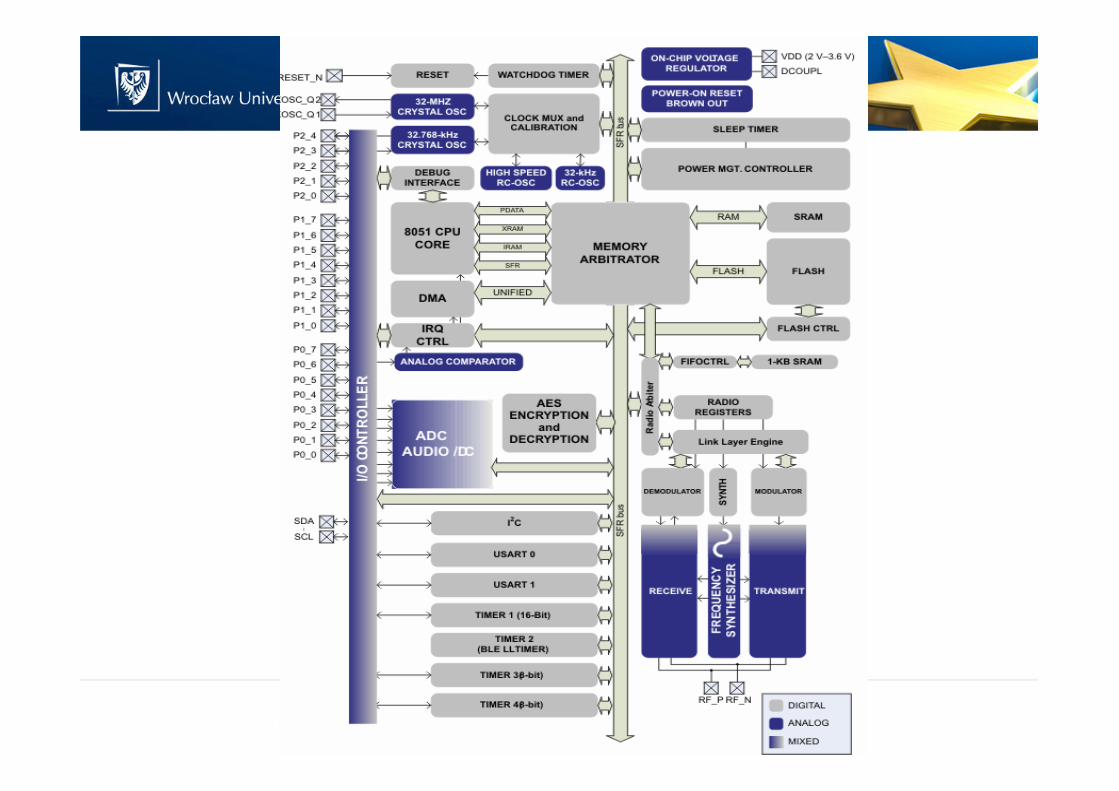
BLE SoC CC2541

CC2541 - features
• Main features:
– 2.4 GHz BLE and Proprietary SoC based on 8051 core
– Supports up to 2Mbps
– Programmable output power up to 0dBm
– Excellent Receiver Sensitivity (–94 dBm at 1MHz)
– 6-mm × 6-mm QFN-40 Package
– Low power:
• Active-Mode RX Down to: 17.9 mA
• Active-Mode TX (0 dBm): 18.2 mA

NFC - Introduction

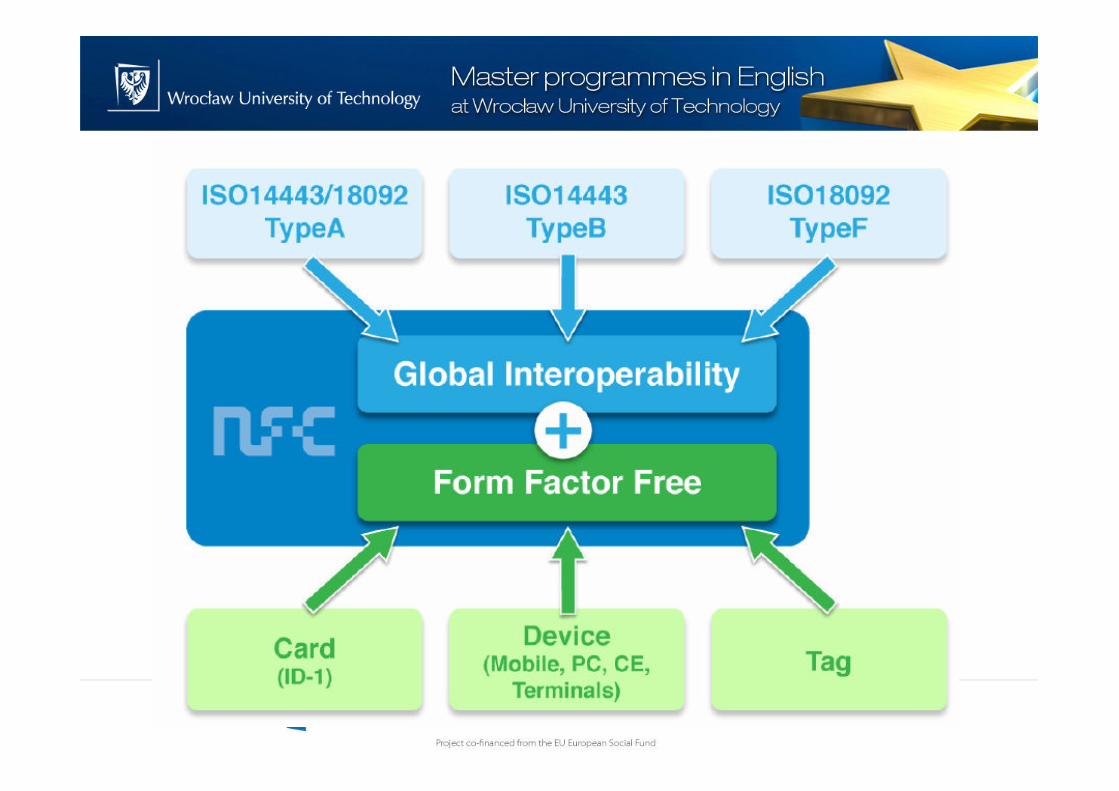
What is NFC?
• NFC means Near Field Communication basingon RFID
• NFC is short-range wireless technology that:– uses radio-frequency waves to transfer data
between a reader and a transmitter
– Is fast and does not require physical sight or contact between reader/scanner and the tagged item
– Usabe range is a few centimeters

Features of NFC
• Used in 1-to-1 communication, but multipoint communication possible
• Maximum transfer bit rate of 800kbps (in standards upto 424kbps)
• Operation at a frequency of 13.5 MHz
• No ethical concerns due to range (only a few cm)

NFC target markets
• Mobile Business– NFC in the mobile phones
• Consumer Electronics– NFC in all DVDs, TVs, cameras
• Computing– NFC in all laptops, printers
• Entertainment, logistics and retail
NFC basic use cases
• Smart Ticketing – Movie theaters or theme parks
• Peer-to-Peer Communication– Transfer digital files from one personal device
to another
• Contact-less mobile Payment– Use the mobile phone as a contact-less credit
card or POS
What is RFID?

NFC – operation modes
• NFC devices operate in two modes:
– Passive communication mode:
• The initiator device provides a carrier fields and the target
device answers by modulating the existing field.
• In this mode, the target device may draw its operating power
from the initiator-provided electromagnetic field, thus
making the target device a transponder

NFC – operation modes
• NFC devices operate in two modes:
– Active communication mode:
• Both initiator and target device communicate by alternately
generating their own fields.
• A device deactivates its RF field while it is waiting for data. In
this mode, both devices typically have power supplies

NFC – operation modes
• In both operation modes there are possible three
data transfer speeds: 106kb/s, 212kb/s and 424
kb/s
• ASK with Manchester or Miller coding is used
• NFC devices are able to receive and transmit data
at the same time. Thus, they can check for
potential collisions if the received signal
frequency does not match with the transmitted
signal’s frequency

NFC vs Bluetooth

NFC vs Bluetooth

NFC Communication
NFC Communication• An NFC device can be either in target mode or
initiator mode
• Passive devices are always in target mode
• The device shall per default be in target mode
unless the application tells it to switch into
initiator mode
• When a device is in target mode it shall wait
silently for an externally generated RF field from
the initiator to activate
NFC Communication
• A device in initiator mode shall perform initial
collision avoidance to detect external RF fields
before activating its RF field.
• The application decides whether active or passive
communication should be applied.
• If passive, it must perform single device detection
before starting the data transfer

NFC Communication
• The basic frame format
• Data frames have to be transmitted in pairs
• A request is transmitted by the initiator and
responded to by the target

NFC Communication
• Target states:– POWER OFF
– SENSE
– RESOLUTION
– SELECTED
– SLEEP
– RESOLUTION*
– SELECTED*
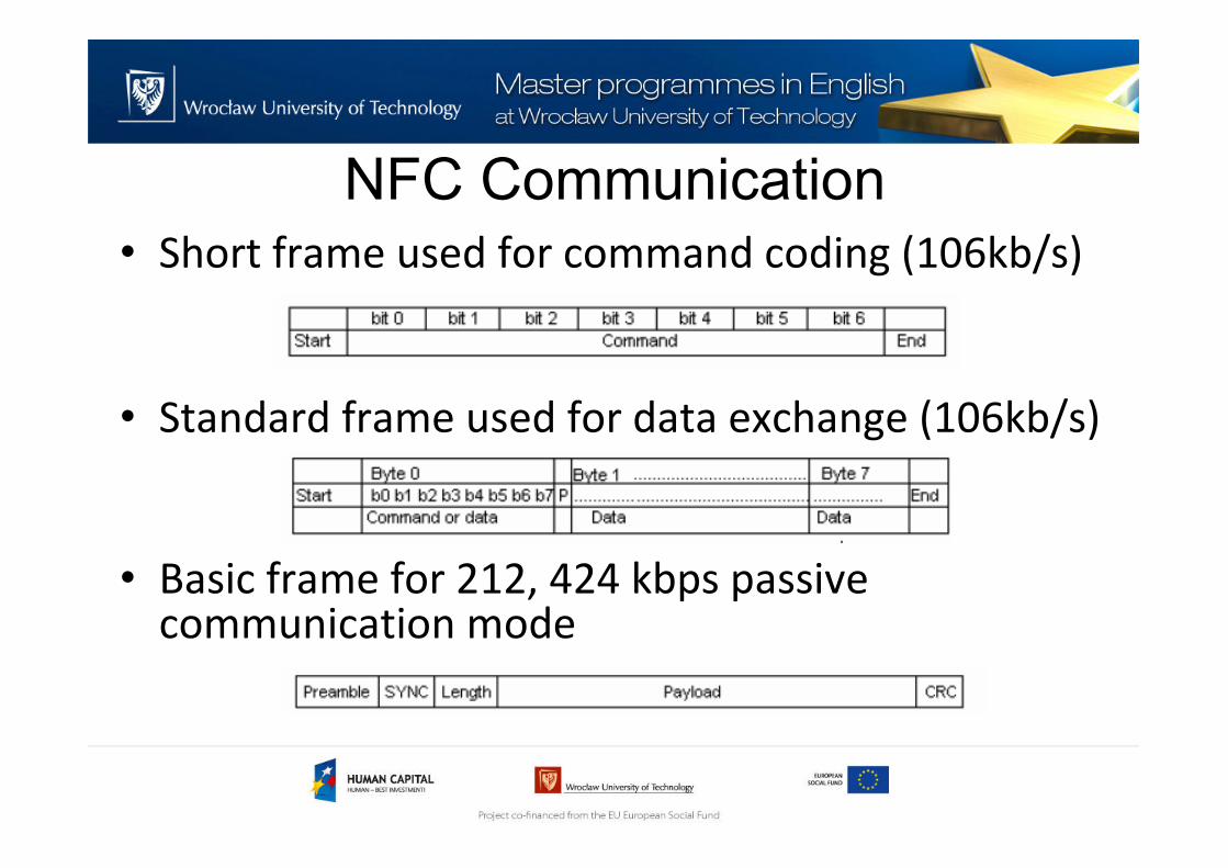
NFC Communication• Short frame used for command coding (106kb/s)
• Standard frame used for data exchange (106kb/s)
• Basic frame for 212, 424 kbps passive communication mode

NFC Communication
• 100% ASK modulation for communication from reader
to transponder
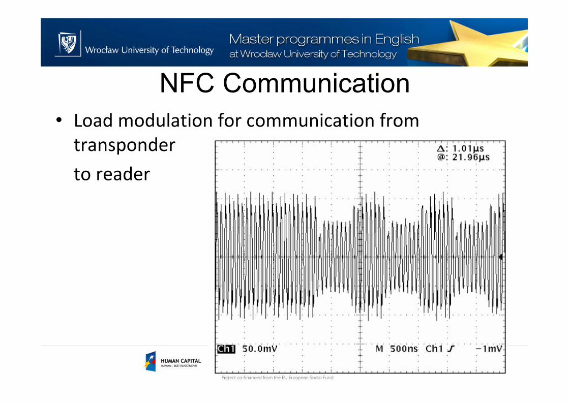
NFC Communication
• Load modulation for communication from
transponder
to reader

NFC Example
part I - professional

TRF7970A – NFC/RFID Transceiver IC

TRF7970A – NFC/RFID Transceiver IC• Features:
– reader/writer IC for contactless communication at 13.56
MHz
– Integrated Encoders, Decoders, and Data Framing for NFC
Initiator, Active and Passive Target Operation for All Three
Bit Rates (106 kbps, 212 kbps, 424 kbps)
– RF Field Detector for NFC Physical Collision Avoidance
– Programmable Output Power: +20 dBm (100 mW), +23 dBm
(200 mW)
– Programmable Modulation Depth
– Parallel or SPI Interface (With 128-Byte FIFO)

TRF7970A – NFC/RFID Transceiver IC

NFC Example
part II - amateur

Amateur version of NFC• Modulation/demodulation scheme:
– FSK
• Hardware
– Transmitter
• PC interface (MAX232A)
• Voltage-Controlled Oscillator (POS+25)
• Power Amplifier (LM6181)
• Loop Antenna
Amateur version of NFC• Modulation/demodulation scheme:
– FSK
• Hardware
– Receiver
• Loop Antenna
• Amplifier (LM6181)
• Phase Lock Loop (NE564)
• PC interface (MAX232A)
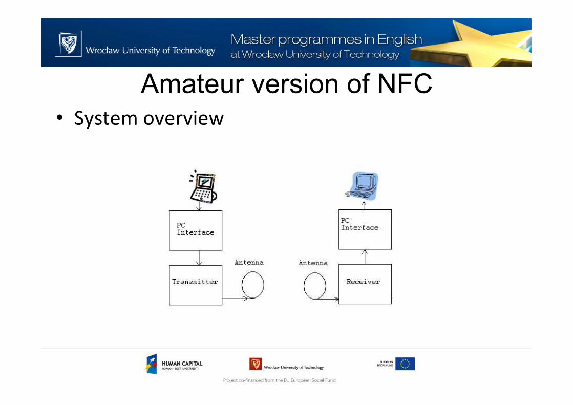
Amateur version of NFC• System overview
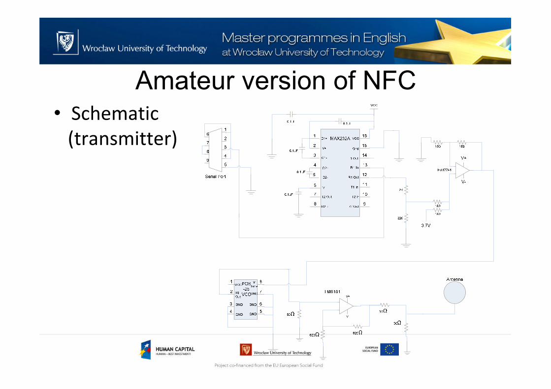
Amateur version of NFC• Schematic
(transmitter)

Amateur version of NFC• Schematic
(receiver)

Thank you for your attention
References
[1] Stonestreet One, „An Introduction to Bluetooth”
[2] Farinaz Edalat, Ganesh Gopal, Saswat Misra, Deepti Rao,
„Bluetooth technology”
[3] BTM-112 documentation, www.maritex.com.pl
[4] http://www.qsl.net/n1bwt/chap1.pdf
[5] http://www.antenna-theory.com/antennas/main.php
[6]
http://www.ti.com/general/docs/datasheetdiagram.tsp?diagra
mId=SWRS110A&genericPartNumber=CC2541&isFunctional=Y&
isFunctional=Y

References
[1] www.nfc-forum.org
[2] www.wikipedia.org
[3] http://www.es.lth.se/teorel/Publications/TEAT-5000-series/TEAT-
5082.pdf
[4]
http://www.cse.fau.edu/~hari/comsoc/Prato_NFC_marketing%20prese
ntation_%20for_IEEE.pdf
[5] http://www.ti.com/lit/ds/symlink/trf7970a.pdf
[6] http://www.ecma-international.org/publications/files/ECMA-ST/Ecma-
340.pdf