the vmware software-defined data center foundation · software-defined data center foundation ......
TRANSCRIPT
The VMware® Software-Defined Data Center FoundationR E F E R E N C E A R C H I T E C T U R E
V E R S I O N 1 . 0
The VMware Software-Defined Data Center Foundation
T E C H N I C A L W H I T E P A P E R / 2
Table of Contents
Overview . . . . . . . . . . . . . . . . . . . . . . . . . . . . . . . . . . . . . . . . . . . . . . . . . . . . . . . . . . . . . . . . . . . . . 3
Audience . . . . . . . . . . . . . . . . . . . . . . . . . . . . . . . . . . . . . . . . . . . . . . . . . . . . . . . . . . . . . . . . . . . . . 3
VMware Software Components . . . . . . . . . . . . . . . . . . . . . . . . . . . . . . . . . . . . . . . . . . . . . . . . . 4
Architectural Overview . . . . . . . . . . . . . . . . . . . . . . . . . . . . . . . . . . . . . . . . . . . . . . . . . . . . . . . . 5
Virtual Management Networks . . . . . . . . . . . . . . . . . . . . . . . . . . . . . . . . . . . . . . . . . . . . . . . . .5
Management Cluster . . . . . . . . . . . . . . . . . . . . . . . . . . . . . . . . . . . . . . . . . . . . . . . . . . . . . . . . . . 7
Edge Cluster . . . . . . . . . . . . . . . . . . . . . . . . . . . . . . . . . . . . . . . . . . . . . . . . . . . . . . . . . . . . . . . . . .9
Compute Clusters . . . . . . . . . . . . . . . . . . . . . . . . . . . . . . . . . . . . . . . . . . . . . . . . . . . . . . . . . . . .10
Physical Component Details . . . . . . . . . . . . . . . . . . . . . . . . . . . . . . . . . . . . . . . . . . . . . . . . . . . 11
Compute . . . . . . . . . . . . . . . . . . . . . . . . . . . . . . . . . . . . . . . . . . . . . . . . . . . . . . . . . . . . . . . . . . . .11
Storage . . . . . . . . . . . . . . . . . . . . . . . . . . . . . . . . . . . . . . . . . . . . . . . . . . . . . . . . . . . . . . . . . . . . . 12
Network . . . . . . . . . . . . . . . . . . . . . . . . . . . . . . . . . . . . . . . . . . . . . . . . . . . . . . . . . . . . . . . . . . . . 12
Software-Defined Data Center Component Details . . . . . . . . . . . . . . . . . . . . . . . . . . . . . . 14
vSphere Data Center Design . . . . . . . . . . . . . . . . . . . . . . . . . . . . . . . . . . . . . . . . . . . . . . . . . .15
vSphere Data Protection . . . . . . . . . . . . . . . . . . . . . . . . . . . . . . . . . . . . . . . . . . . . . . . . . . . . . . 17
NSX for vSphere . . . . . . . . . . . . . . . . . . . . . . . . . . . . . . . . . . . . . . . . . . . . . . . . . . . . . . . . . . . . 18
Monitoring . . . . . . . . . . . . . . . . . . . . . . . . . . . . . . . . . . . . . . . . . . . . . . . . . . . . . . . . . . . . . . . . . . 20
vRealize Operations . . . . . . . . . . . . . . . . . . . . . . . . . . . . . . . . . . . . . . . . . . . . . . . . . . . . . . . 20
Conclusion . . . . . . . . . . . . . . . . . . . . . . . . . . . . . . . . . . . . . . . . . . . . . . . . . . . . . . . . . . . . . . . . . . 21
The VMware Validated Design Team . . . . . . . . . . . . . . . . . . . . . . . . . . . . . . . . . . . . . . . . . . . . 22
About the Author . . . . . . . . . . . . . . . . . . . . . . . . . . . . . . . . . . . . . . . . . . . . . . . . . . . . . . . . . . . . 22
T E C H N I C A L W H I T E P A P E R / 3
The VMware Software-Defined Data Center Foundation
OverviewThis reference architecture describes the implementation of a software-defined data center (SDDC) that leverages the latest VMware components and capabilities. The reference architecture is built on the Foundation VMware Validated Design.
The Foundation VMware Validated Design is the core of all higher-level VMware Validated Designs. Foundation describes a scalable, resilient, best-practice configuration on which all additional functionality is layered. The Foundation configuration uses industry-standard servers, IP-based and VMware Virtual SAN™ storage, and software-defined networking to support a scalable and redundant architecture.
The VMware Validated Design process gathers data from customer support, VMware IT, and VMware and partner professional services to create a standardized configuration that meets the majority of customer requirements. Internally, VMware engineering teams test new product capabilities, installations, upgrades, and more, against the standardized configuration. VMware and partner professional services teams build delivery kits based on this design, knowing that they are deploying with the best possible configuration. Customers planning “do it yourself” deployments also benefit from following this architecture, confident that future product upgrades, patches, and so on, have already been tested against a configuration identical to theirs.
AudienceThis document will assist those who are responsible for infrastructure services, including enterprise architects, solution architects, sales engineers, field consultants, advanced services specialists, and customers. This guide provides an example of a successful deployment of an SDDC.

T E C H N I C A L W H I T E P A P E R / 4
The VMware Software-Defined Data Center Foundation
VMware Software ComponentsThis architecture uses the following VMware software components.
PRODUCT VERSION DESCRIPTION
VMware vSphere with Operations Management
6.1 VMware vSphere® with Operations Management™ delivers VMware vSphere optimized for efficient server virtualization management by adding critical capacity management and performance monitoring capabilities used to deliver the SDDC.
In this architecture, users leverage VMware vSphere with Operations Management Enterprise Plus Edition 6.1, which includes VMware vSphere® Enterprise Plus Edition™ 6.0 U1, VMware vSphere Data Protection™ 6.1, and VMware vRealize™ Operations Manager™ 6.1.
VMware vCenter Server 6.0 U1 VMware vCenter Server™ is the central platform for managing and configuring the VMware ESXi™ hypervisor. VMware vSphere Web Client is the centralized point of administration for compute clusters and all networking services provided by VMware NSX™ for vSphere®.
VMware Virtual SAN 6.1 Virtual SAN is radically simple, hypervisor-converged storage for virtual machines. It delivers enterprise-class, high-performance storage for virtualized applications, including business-critical applications.
VMware NSX for vSphere 6.2 NSX for vSphere exposes a complete suite of simplified logical networking elements and services including virtual switches, routers, firewalls, load balancers, virtual private network (VPN), QoS, monitoring, and security.
Table 1. Components

T E C H N I C A L W H I T E P A P E R / 5
The VMware Software-Defined Data Center Foundation
Architectural OverviewThis design uses three cluster types, each with its own distinct function. It provides a management plane that is separate from the user workload (compute) virtual machines. It also leverages an edge cluster, which provides dedicated resources for network services such as VMware NSX Edge™ devices, which provide access to the corporate network and the Internet.
Virtual Management NetworksTable 2 provides a quick introductory overview of VMware NSX™ and networking terms and acronyms.
TERM DEFINITION
VLAN A VLAN is used to partition a physical network into multiple distinct broadcast domains.
NSX for vSphere NSX for vSphere is virtual networking and security software that enables the software-defined network.
Virtual switch The NSX virtual switch abstracts the physical network and provides access-level switching in the hypervisor. It is central to network virtualization because it enables logical networks that are independent of physical constructs such as VLANs.
VPN A VPN can be used to connect networks to each other or a single machine to a network.
MPLS Multiprotocol Label Switching (MPLS) is a scalable, protocol-independent transport mechanism. In an MPLS network, data packets are assigned labels. Packet-forwarding decisions are made solely on the contents of this label, without the need for examination of the packet itself. This enables users to create end-to-end circuits across any type of transport medium, using any protocol.
Table 2. VMware NSX Overview
This design utilizes NSX for vSphere virtual switches in the management cluster. VMware vRealize Operations™ has its own VMware NSX virtual switch and NSX Edge device. As new management or monitoring solutions are added, they too are placed on their own VMware NSX virtual switch with a corresponding NSX Edge device. The grouping of these virtual machines onto a virtual switch is referred to as a virtual management network.
Virtual management networks are connected to both the vSphere management VLAN and the external VLAN via an NSX Edge device. Routing is configured between the virtual management network and the vSphere management VLAN. This enables the solution and virtual machines on the vSphere management VLAN, such as the vCenter Server instance, to communicate without exposing the management servers directly to end users.
External connectivity to the business function of the virtual management network is provided by a load balancer’s virtual IP on the external VLAN. External connectivity to the management function of the virtual management network is provided, as needed, by the method—routing to the virtual management network using Ethernet, MPLS, VPN, jump hosts, or other means—that best fits the customer’s environment.
Another option is to deploy the VMware NSX distributed logical router and to enable a dynamic routing protocol, such as OSPF, between the router and the top-of-rack switches. This enables access to all virtual machines on the virtual switches by advertising their IP addresses to the rest of the network. Virtual management networks still require NSX Edge devices to provide load balancer functionality.

T E C H N I C A L W H I T E P A P E R / 6
The VMware Software-Defined Data Center Foundation
Virtual management networking isolates management solutions from each other and from compute workloads. More important, it enables disaster recovery of the automation and monitoring stacks without having to change the IP addresses of the virtual machines. The virtual machines can be moved to precreated virtual switches in another site that has been configured the same as the primary site, enabling quick recovery of the solutions.
Top-of-Rack SwitchesVLAN 1701 SVI - 10.155.170.1VLAN 1680 SVI - 10.155.168.1
Static Routes192.168.20.0/24 - 10.155.168.75192.168.21.0/24 - 10.155.168.76192.168.22.0/24 - 10.155.168.77
External VLAN(1701) – 10.155.170.0/24
vSphere Management VLAN(1680) – 10.155.168.0/24
NSX Edge192.168.21.1 (Internal)10.155.168.75 (vSphere)10.155.170.150 (External)
vRealize Operations Virtual Switch192.168.20.0/24
VM VM VM
Figure 1. Example Using Static Routing

T E C H N I C A L W H I T E P A P E R / 7
The VMware Software-Defined Data Center Foundation
External VLAN(1701) – 10.155.170.0/24
vSphere Management VLAN(1680) – 10.155.168.0/24
Top-of-Rack Switches
OSPF
Distributed Logical Router
NSX Edge192.168.20.1 (Internal)
vRealize Operations Virtual Switch192.168.20.0/24
VM VM VM
Figure 2. Example Using Dynamic Routing
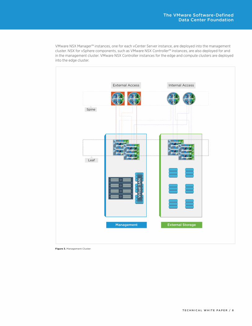
Management ClusterThe management cluster contains the management and monitoring solutions for the entire design. A single management cluster can support multiple pods of edge and compute clusters. The minimum number of hosts required in the management cluster is three, although four hosts are recommended for availability and performance. The management cluster can scale out as the number of edge and compute pods increases.
With the exception of vSphere Data Protection, which stores all backups on NFS storage, all virtual machines utilize Virtual SAN storage.
A single vCenter Server instance manages the resources in the management cluster. Additional vCenter Server instances manage edge and compute clusters. A Platform Services Controller™ is deployed for each vCenter Server instance. The Platform Services Controllers are joined to the same VMware vCenter Single Sign-On domain, enabling features such as Enhanced Linked Mode and cross vCenter Server VMware vSphere vMotion®. For more information on the Platform Services Controller and new enhancements in vSphere 6.0, see the VMware vCenter Server 6.0 Deployment Guide and the What’s New in vSphere 6.0 white papers.
T E C H N I C A L W H I T E P A P E R / 8
The VMware Software-Defined Data Center Foundation
VMware NSX Manager™ instances, one for each vCenter Server instance, are deployed into the management cluster. NSX for vSphere components, such as VMware NSX Controller™ instances, are also deployed for and in the management cluster. VMware NSX Controller instances for the edge and compute clusters are deployed into the edge cluster.
Leaf
Vir
tual
SA
N
External Access Internal Access
Management External Storage
Spine
Figure 3. Management Cluster

T E C H N I C A L W H I T E P A P E R / 9
The VMware Software-Defined Data Center Foundation
Edge ClusterThe edge cluster simplifies the physical network configuration. It is used to deliver networking services to the compute cluster virtual machines. All external networking, including corporate and Internet, for user-workload virtual machines is accessed via the edge cluster.
The minimum edge cluster size is three hosts, but it can scale depending on the volume of services required by the compute cluster virtual machines.
Vir
tual
SA
N
Leaf
External Access Internal Access
Edge
Spine
Figure 4. Edge Cluster
T E C H N I C A L W H I T E P A P E R / 1 0
The VMware Software-Defined Data Center Foundation
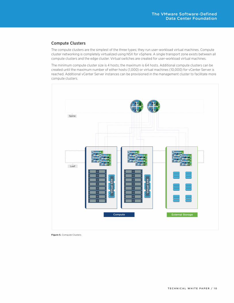
Compute ClustersThe compute clusters are the simplest of the three types; they run user-workload virtual machines. Compute cluster networking is completely virtualized using NSX for vSphere. A single transport zone exists between all compute clusters and the edge cluster. Virtual switches are created for user-workload virtual machines.
The minimum compute cluster size is 4 hosts; the maximum is 64 hosts. Additional compute clusters can be created until the maximum number of either hosts (1,000) or virtual machines (10,000) for vCenter Server is reached. Additional vCenter Server instances can be provisioned in the management cluster to facilitate more compute clusters.
External Storage
Leaf
Vir
tual
SA
N
Vir
tual
SA
N
Compute
Spine
Figure 5. Compute Clusters

T E C H N I C A L W H I T E P A P E R / 1 1
The VMware Software-Defined Data Center Foundation
Physical Component DetailsComputeTable 3 lists the recommended minimum physical server configuration.
COMPONENT SPECIFICATION
CPU 24GHz – Two 2GHz six-core CPUs (12 total cores)
Memory 256GB ECC RAM
SD 6GB SD card boot device
HDD controller Virtual SAN certified controller*
Flash 500GB Virtual SAN certified Flash device*
HDD Two 1TB Virtual SAN certified HDDs*
Network interface cards Two 10Gb network adapters
Power supplies Redundant
Fans Redundant
Table 3. Minimum Physical Server Configuration
* Virtual SAN certified devices can be found at http://www.vmware.com/resources/compatibility/search.php?deviceCategory=vsan.
For ease of management and to guarantee resource availability as the solution grows, all physical server hardware, regardless of cluster, utilizes the same configuration.
T E C H N I C A L W H I T E P A P E R / 1 2
The VMware Software-Defined Data Center Foundation
StorageThe management cluster utilizes Virtual SAN in addition to NFS datastores. Virtual machines reside on Virtual SAN; vSphere Data Protection backups reside on NFS datastores.
The edge cluster utilizes Virtual SAN, which serves the VMware NSX Controller instances for the edge and compute clusters as well as NSX Edge devices.
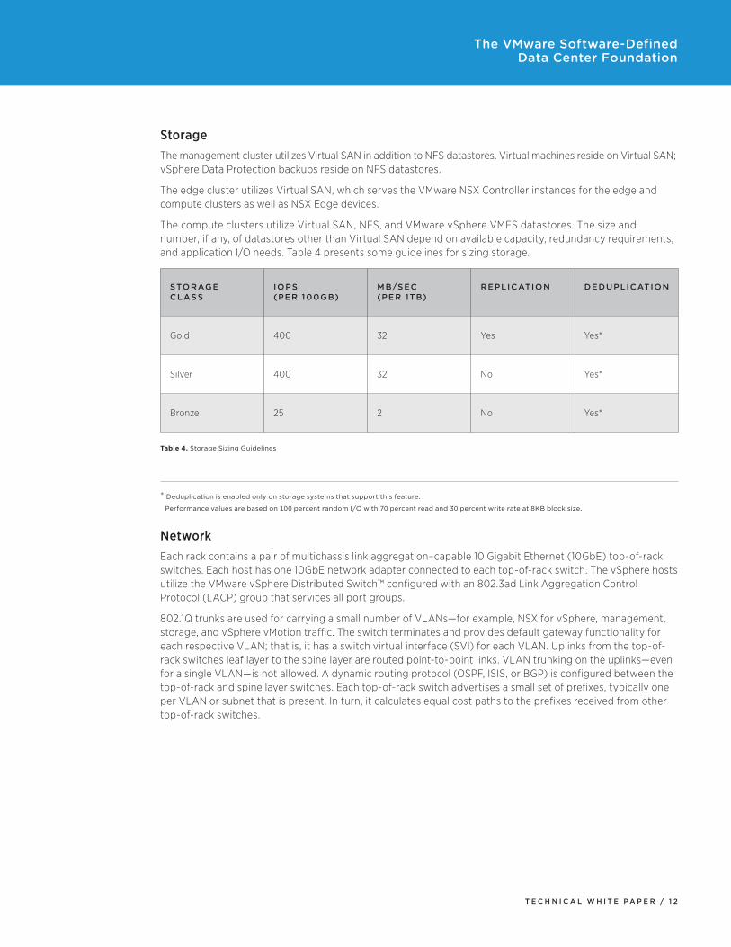
The compute clusters utilize Virtual SAN, NFS, and VMware vSphere VMFS datastores. The size and number, if any, of datastores other than Virtual SAN depend on available capacity, redundancy requirements, and application I/O needs. Table 4 presents some guidelines for sizing storage.
STORAGE CLASS
IOPS (PER 100GB)
MB/SEC (PER 1TB)
REPLICATION DEDUPLICATION
Gold 400 32 Yes Yes*
Silver 400 32 No Yes*
Bronze 25 2 No Yes*
Table 4. Storage Sizing Guidelines
* Deduplication is enabled only on storage systems that support this feature.
Performance values are based on 100 percent random I/O with 70 percent read and 30 percent write rate at 8KB block size.
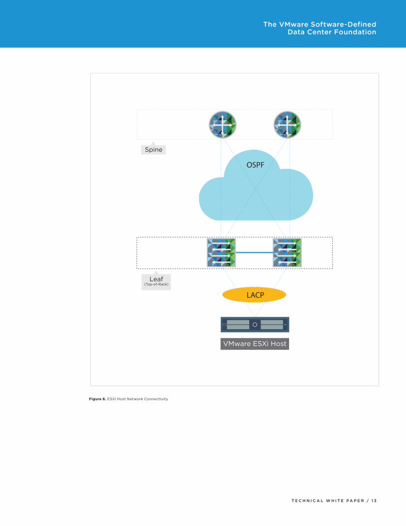
NetworkEach rack contains a pair of multichassis link aggregation–capable 10 Gigabit Ethernet (10GbE) top-of-rack switches. Each host has one 10GbE network adapter connected to each top-of-rack switch. The vSphere hosts utilize the VMware vSphere Distributed Switch™ configured with an 802.3ad Link Aggregation Control Protocol (LACP) group that services all port groups.
802.1Q trunks are used for carrying a small number of VLANs—for example, NSX for vSphere, management, storage, and vSphere vMotion traffic. The switch terminates and provides default gateway functionality for each respective VLAN; that is, it has a switch virtual interface (SVI) for each VLAN. Uplinks from the top-of-rack switches leaf layer to the spine layer are routed point-to-point links. VLAN trunking on the uplinks—even for a single VLAN—is not allowed. A dynamic routing protocol (OSPF, ISIS, or BGP) is configured between the top-of-rack and spine layer switches. Each top-of-rack switch advertises a small set of prefixes, typically one per VLAN or subnet that is present. In turn, it calculates equal cost paths to the prefixes received from other top-of-rack switches.
T E C H N I C A L W H I T E P A P E R / 1 3
The VMware Software-Defined Data Center Foundation
OSPF
Spine
Leaf(Top-of-Rack)
LACP
VMware ESXi Host
Figure 6. ESXi Host Network Connectivity

T E C H N I C A L W H I T E P A P E R / 1 4
The VMware Software-Defined Data Center Foundation
Software-Defined Data Center Component DetailsIn this section, we will define the VMware software components and their configuration in enabling this solution.
COMPONENT NUMBER DEPLOYED
DEPLOYED LOCATION
CONNECTED NETWORK
Platform Services Controller
2 Management cluster vSphere management VLAN
vCenter Server 2 Management cluster vSphere management VLAN
ESXi hosts Minimum of 1 1 (varies based on compute cluster requirements)
4 – Management cluster3 – Edge cluster4 – Compute cluster
ESXi management VLAN
vSphere Data Protection
1 Management cluster vSphere management VLAN
NSX Manager 2 Management cluster vSphere management VLAN
VMware NSX Controller
6 3 – Management cluster3 – Edge cluster
vSphere management VLAN
vRealize Operations Manager
4 (1 master, 1 master replica, 2 data nodes)
Management cluster vROps
Table 5. SDDC Component Details

T E C H N I C A L W H I T E P A P E R / 1 5
The VMware Software-Defined Data Center Foundation
vSphere Data Center DesignThe vSphere Enterprise Plus Edition is the core that enables the SDDC. All vSphere hosts are stateful installs—that is, the ESXi hypervisor is installed to a local SD card.
ATTRIBUTE SPECIFICATION
ESXi version 6.0 U1
Number of hosts 1 1
Number of CPUs per host 2
Number of cores per CPU 6
Core speed 2GHz
Memory 256GB
Number of network adapters 2 x 10Gb
Table 6. ESXi Host Details
The solution uses VMware vSphere High Availability (vSphere HA) and VMware vSphere Distributed Resource Scheduler™ (vSphere DRS). vSphere HA is set to monitor both hosts and virtual machines. Its admission control policy utilizes a percentage of cluster resources reserved—25 percent in a four-node cluster—guaranteeing sustainability with one node failure. To calculate the percentage, divide 100 by the number of hosts in a cluster; then, multiply the result by the number of hosts that can be eliminated while still guaranteeing resources for the virtual machines in the cluster. For example, an eight-host cluster for which sustainability for a two-host failure is the goal would be 100 ÷ 8 = 12.5 x 2 = 25 percent. vSphere DRS is set to fully automated mode.
VLAN ID FUNCTION
14 VXLAN (management cluster)
24 VXLAN (edge cluster)
34 VXLAN (compute clusters)
970 ESXi management
980 vSphere vMotion
1020 IP storage (NFS)
1680 vSphere management
1701 External
3002 Virtual SAN
Table 7. VLAN IDs and Functions

T E C H N I C A L W H I T E P A P E R / 1 6
The VMware Software-Defined Data Center Foundation
PORT GROUP VDS VLAN ID
vDS-Mgmt-ESXi vDS-Mgmt 970
vDS-Mgmt-Ext vDS-Mgmt 1701
vDS-Mgmt-NFS vDS-Mgmt 1020
vDS-Mgmt-vMotion vDS-Mgmt 980
vDS-Mgmt-VSAN vDS-Mgmt 3002
vDS-Mgmt-vSphere-Management vDS-Mgmt 1680
VXLAN (VMware NSX autocreated) vDS-Mgmt 14
vDS-Edge-ESXi vDS-Edge 970
vDS-Edge-Ext vDS-Edge 1701
vDS-Edge-vMotion vDS-Edge 980
vDS-Edge-VSAN vDS-Edge 3002
vDS-Edge-vSphere-Management vDS-Edge 1680
VXLAN (VMware NSX autocreated) vDS-Edge 24
vDS-Comp-ESXi vDS-Comp 970
vDS-Comp-NFS vDS-Comp 1020
vDS-Comp-vMotion vDS-Comp 980
vDS-Comp-VSAN vDS-Comp 3002
VXLAN (VMware NSX autocreated) vDS-Comp 34
Table 8. Port Groups
DATASTORE TYPE FUNCTION
DS-VSAN-MGMT01 Virtual SAN Management cluster virtual machine datastore
DS-NFS-MGMT01 NFS vSphere Data Protection backups
DS-VSAN-EDGE01 Virtual SAN Edge cluster virtual machine datastore
DS-VSAN-COMP01 Virtual SAN Gold-tier storage
DS-NFS-COMP01 NFS Silver-tier storage
DS-NFS-COMP02 NFS Silver-tier storage
Table 9. Datastores

T E C H N I C A L W H I T E P A P E R / 1 7
The VMware Software-Defined Data Center Foundation
ATTRIBUTE SPECIFICATION
vCenter version 6.0 U1 (appliance)
Quantity Four (two Platform Services Controllers, two vCenter Server instances)
Appliance size Small for management vCenter Server, large for compute vCenter Server
Table 10. VMware vCenter Configuration
ATTRIBUTE SPECIFICATION
Data center object WDC01
Enhanced Linked Mode Automatic by joining same vCenter Single Sign-On domain
Table 11. VMware vCenter Data Center Configuration
vSphere Data ProtectionvSphere Data Protection is deployed in the management cluster and is responsible for backups and restores of the virtual machines residing in the management cluster.
A backup policy was created for each application such as vCenter Server, vRealize Operations, and so on. Backup frequency and retention periods vary based on organizational requirements. Nightly backup of all virtual machines and databases is recommended.
Figure 7. vSphere Data Protection

T E C H N I C A L W H I T E P A P E R / 1 8
The VMware Software-Defined Data Center Foundation
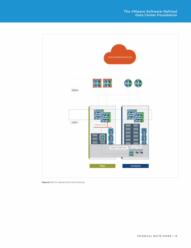
NSX for vSphereNSX for vSphere provides the virtual switches, routing, and load balancer services used to create the SDDC. All virtual machine traffic, excluding that on the vSphere management VLAN, is encapsulated using NSX for vSphere. All virtual machine–to–virtual machine, or east–west, traffic is encapsulated and then routed between the virtual tunnel endpoints (VTEPs) of the host, where it is decapsulated and delivered to the virtual machine. When a request to or from the external network is serviced, it travels through the NSX Edge device in the edge cluster, which provides all north–south routing—that is, routing to and from external networks.
NSX for vSphere has a one-to-one relationship with vCenter Server, so two NSX Manager instances are deployed, one for the management cluster vCenter Server instance and the other for the edge and compute cluster vCenter Server instance. These are both deployed in the management cluster.
NSX for vSphere utilizes controller virtual machines to implement the network control plane. The VMware NSX Controller instances must be deployed in odd numbers to avoid a split-brain scenario. As such, three controllers per NSX for vSphere instance are deployed. The VMware NSX Controller instances for the management cluster are deployed into the management cluster itself; the instances for the edge and compute clusters are deployed into the edge cluster.
The ESXi hosts must be prepared for NSX for vSphere. The following values are used:
SPECIFICATION VALUE
MTU 9000
Teaming mode LACP V2
VLAN 14 (management) 24 (edge) 34 (compute)
Segment IDs 5000–5200
Transport zones Management (management cluster) Compute (edge and compute clusters)
Table 12. NSX for vSphere Values
To enable external (north–south) connectivity for the compute workloads, an NSX Edge router is deployed in HA mode. This NSX Edge instance is referred to as the provider edge. One interface is connected to the external network; another is connected to an NSX virtual switch, which is also connected to an NSX Edge router. The NSX Edge routers are configured with OSPF to facilitate the exchange of routing information. This enables the virtual machines on the NSX virtual switch to communicate with the external network and vice versa as long as firewall rules permit the communication.
T E C H N I C A L W H I T E P A P E R / 1 9
The VMware Software-Defined Data Center Foundation
Leaf
Vir
tual
SA
N
Vir
tual
SA
N
External VLAN
VXLAN 5001Compute Transport Zone
VM VM
Edge
External Network/Internet
Compute
Spine
Figure 8. NSX for vSphere North–South Routing

T E C H N I C A L W H I T E P A P E R / 2 0
The VMware Software-Defined Data Center Foundation
MonitoringMonitoring the performance, capacity, health, and logs in any environment is critical.
Using vRealize Operations along with vRealize Log Insight is a unified management solution for performance management, capacity optimization, and real-time log analytics. Predictive analytics leverages both structured and unstructured data to enable proactive issue avoidance and faster problem resolution.
The solution extends intelligent operations management beyond vSphere to include operating systems, physical servers, and storage and networking hardware. It is supported by a broad marketplace of extensions for third-party tools.
vRealize OperationsvRealize Operations provides operations dashboards, performance analytics, and capacity optimization capabilities needed to gain comprehensive visibility, proactively ensure service levels, and manage capacity in dynamic virtual and cloud environments.
vRealize Operations is deployed as a virtual appliance and is distributed in the OVA format. In this architecture, vRealize Operations is deployed on an NSX virtual switch. Four vRealize Operations appliances are deployed. The first is configured as the master node, the next as the master replica, and the last two as data nodes. The four appliances access the vSphere management VLAN via the NSX Edge device configured with either static or dynamic routing. The NSX Edge device also load-balances the four virtual appliances on port 443, providing access to the vRealize Operations cluster via a single FQDN.
External VLAN
vSphere VLAN
NSX Edge192.168.21.1 (Internal)10.155.168.76 (vSphere)10.155.170.152 (External)
VM VM
Load-Balanced IPvRealize Operations Appliances
NSX vSwitch 192.168.21.0/24
VM VM
10.155.170.10
Figure 9. vRealize Operations

T E C H N I C A L W H I T E P A P E R / 2 1
The VMware Software-Defined Data Center Foundation
To ensure a complete picture of how the environment is running, vRealize Operations is configured to monitor the management, edge, and compute vCenter Server instances. Additionally, the NSX for vSphere content pack is installed and configured to provide insight into the virtualized networking environment.
.
Figure 10. vRealize Operations Dashboard
vRealize Operations requires updates to the default monitoring settings for most organizations. For more information on how to customize vRealize Operations for a specific environment, see the vRealize Operations documentation.
ConclusionThe reference architecture presented in this paper describes the implementation of a software-defined data center (SDDC) that uses the latest VMware components as its foundation. Customers following this architecture can be confident that they will have the best possible supported configuration, one that is fully backed by the VMware Validated Design process.
For a guided tutorial that shows step-by-step instructions for deploying this configuration, see http://featurewalkthrough.vmware.com/#!/defining-the-sddc/dcv.

T E C H N I C A L W H I T E P A P E R / 2 2
The VMware Software-Defined Data Center Foundation
The VMware Validated Design TeamBlaine Christian, Scott Faulkner, Phil Weiss, Christian Elsen, Nik Gibson, Randy Jones, William Lam, Nick Marshall, Paudie O’Riordan, Kamu Wanguhu, Steven Ching, Michelle Gress, Christine Zak, Yu-Shen Ng, Bob Perugini, Justin King, Karthik Narayan, Sunny Bhatia, Mandar Dhamankar, Olga Efremov, David Gress, Kristopher Inglis, Rama Maram, Hari Krishna Meka, Arvind Patil, Venkat Rangarajan, Lakshmanan Shanmugam, Todor Spasov, Georgi Staykov, Antony Stefanov, Kevin Teng, Todor Todorov, Tuan Truong, Randy Tung, Shivaprasad Adampalli Venkateshappa, Lap Vong, Zhuangqian Zhang, and Mike Brown
About the AuthorMike Brown is a senior technical marketing architect in the Integrated Systems Business Unit. Mike’s focus is on reference architectures for VMware vCloud Suite® and the software-defined data center. He has multiple industry certifications, including VMware Certified Design Expert (VCDX), VMware Certified Advanced Professional – Cloud, and VMware Certified Professional – Network Virtualization.
Follow Mike on the vSphere Blog and on Twitter @vMikeBrown.

VMware, Inc. 3401 Hillview Avenue Palo Alto CA 94304 USA Tel 877-486-9273 Fax 650-427-5001 www .vmware .comCopyright © 2015 VMware, Inc . All rights reserved . This product is protected by U .S . and international copyright and intellectual property laws . VMware products are covered by one or more patents listed at http://www .vmware .com/go/patents . VMware is a registered trademark or trademark of VMware, Inc . in the United States and/or other jurisdictions . All other marks and names mentioned herein may be trademarks of their respective companies . Item No: VMW-RA-Sftwr-Def-Data-Cntr-USLET-101 Docsource: OIC-FP-1379