universal software defined radio development platform meeting proceedings/rto... · universal...
TRANSCRIPT

RTO-MP-IST-062 11 - 1
UNCLASSIFIED/UNLIMITED
Universal Software Defined Radio Development Platform
Dr. Bertalan Eged*, Benjamin Babják** *Sagax Communication Ltd., Haller u. 11-13. Budapest 1096 Hungary
**Budapest University of Technology and Economics, Deparment of Broadband Infocommunications and Electromagnetic Theory
Goldmann Gy. tér 3. Budapest 1111
Hungary
ABSTRACT
Software defined radio components will play important role in future of wireless communication networks. The paper deals with the introduction of a prototype platform for software defined radio solutions, which supports the development of the waveforms and applications for reconfigurable radio components with adaptive and reactive modulation formats. High-speed, high-bandwidth converter family is shown with some example applications to demonstrate the capability of the components.
1.0 INTRODUCTION
As an introduction for the topic let us summarize some basic characteristic of existing and evolving radio communication. As you may know the armed forces are equipped with a lot of communication devices including radio equipments and systems. E.g. in the US Army up to 25-30 radio-families are in use, which applied in a complex mission have to co-operate with Navy and Air force systems too. Assuming an operation carried out by international troops the number of systems and equipments becomes even larger, and the problem of interoperability becomes sorely serious.
More complex missions require more complex communication systems. Each newly added system specification is accompanied by the demand of new radio devices, requiring application specific hardware and software components. Manifolding new radio equipment adds significant costs to service and maintenance of these systems.
2.0 SOFTWARE DEFINED RADIO TECHNOLOGY
Let us examine how Software Defined Radio Technology could help us solve the previously mentioned and other problems. The main principle of SDR is that considerable part of the radio is realized as software running on programmable and reconfigurable hardware devices. The hardware itself is referred to as the „radio platform”, while the different layers of software are called „application framework”. This scheme provides universal and reusable components, which save costs and can be easily upgraded. It is important to emphasize that although it is an enabling technology, SDR itself is not an actual product. SDR is rather a kind of principle to build radio devices on. SDR covers different kind of hardware and software components, which can be stand-alone products used to build SDR based solutions. The providers and users of this technology joined in an industrial alliance called SDR Forum [1].
Eged, B.; Babják, B. (2006) Universal Software Defined Radio Development Platform. In Dynamic Communications Management (pp. 11-1 – 11-12). Meeting Proceedings RTO-MP-IST-062, Paper 11. Neuilly-sur-Seine, France: RTO. Available from: http://www.rto.nato.int/abstracts.asp.
UNCLASSIFIED/UNLIMITED

Universal Software Defined Radio Development Platform
11 - 2 RTO-MP-IST-062
UNCLASSIFIED/UNLIMITED
UNCLASSIFIED/UNLIMITED
The SDR architecture (figure 1.) consists of functional hardware elements connected through open interfaces, and firmware procedures for adding software specific tasks to each of the functional areas. These parts of the model are jointly referred to as the „hardware platform”.
The software necessary to operate is called the „operating software” (OS) running on the hardware based on its firmware. This operating environment provides a common interface for the upper layer. With the common interface we have a radio infrastructure, which is ready to run application specific software modules completing the whole solution.
Antennahardware
Firmware
RFhardware
Firmware
Modemhardware
Firmware
TRANSEChardware
Firmware
INFOSEChardware
Firmware
Codinghardware
Firmware Firmware
User I/Ohardware
Antennahardware
Firmware
RFhardware
Firmware
Modemhardware
Firmware
TRANSEChardware
Firmware
INFOSEChardware
Firmware
Codinghardware
Firmware Firmware
User I/Ohardware
Commonsoftware
OS
Commonsoftware
OS
Commonsoftware
OS
Commonsoftware
OS
Commonsoftware
OS
Commonsoftware
OS
Commonsoftware
OS
Commonsoftware
OS
Commonsoftware
OS
Commonsoftware
OS
Commonsoftware
OS
Commonsoftware
OS
Commonsoftware
OS
Commonsoftware
OS
Antennaspecificmodules
RFspecificmodules
Modemspecificmodules
TRSECspecificmodules
ISECspecificmodules
Codungspecificmodules
User I/Ospecificmodules
Antennaspecificmodules
RFspecificmodules
Modemspecificmodules
TRSECspecificmodules
ISECspecificmodules
Codungspecificmodules
User I/Ospecificmodules
Har
dwar
epl
atfo
rmH
ardw
are
plat
form
Rad
ioin
frast
ruct
ure
Rad
ioin
frast
ruct
ure
Rad
ioso
lutio
nR
adio
solu
tion
Figure 1: SDR architecture model
The common interface also known as software API layer is very important, since it allows solutions and platforms provided by different vendors to work together. The common software API layer shown in figure 2. is standardized with common functions having open and published interfaces.
Common (Standard) Application Programming Interface
Platform(hardware)Vendor #1
Platform(hardware)Vendor #2
Platform(hardware)Vendor #n
Platform(hardware)Vendor #1
Platform(hardware)Vendor #2
Platform(hardware)Vendor #n
Solution(software)Vendor #1
Solution(software)Vendor #2
Solution(software)Vendor #n
Solution(software)Vendor #1
Solution(software)Vendor #2
Solution(software)Vendor #n
Figure 2: SDR open architecture
Currently the accepted common interface for military applications is the Software Communication Architecture developed by the Joint Tactical Radio System (JTRS) project.
„The Joint Tactical Radio System is a DoD initiative. JTRS is designed to provide a flexible new approach to meet diverse warfighter communication needs through software programmable radio technology.”
Quoted from JTRS homepage [2].

Universal Software Defined Radio Development Platform
RTO-MP-IST-062 11 - 3
UNCLASSIFIED/UNLIMITED
UNCLASSIFIED/UNLIMITED
The key result of the JTRS Program shown in figure 3. is the specification of the Software Communications Architecture (SCA), which serves as standard for (nearly) all military SDRs [3]. It is a framework of an open, distributed, object oriented architecture, and it separates the application (waveform functionality) from the Operating Environment. SCA defines common interfaces for the behaviour and the installation of software components. Furthermore it defines common services and Application Programming Interface to support the portability of devices and applications.
Figure 3: Software Communication Architecture
3.0 RADIO DEVICE MODELLING
Traditionally a radio has been considered to be the „box” connecting to the antenna and everything behind that. However many system designs are segmented into separate subsystems: RF to IF down-conversion, baseband conversion and demodulation, man-machine interface elements. The high-level functional model of the SDR radio platform (figure 4.) consists of only three main elements: the analogue front-end, the domain conversion and the digital back-end.
Analogprocessing
Digitalprocessing
Domainconversion
A/D and D/A
Figure 4: SDR based radio implementation
The analogue front-end is responsible for frequency conversion between the transmitted signal frequency and the digitally processable frequency and bandwidth. The front-end is based on analogue amplifiers, mixers, filters and frequency sources. The domain converter responsible for the conversion between the analogue and digital domain are based on high-speed, wideband A/D and D/A converters. Properties of the domain converters highly influence the functionality of soft radio platforms. The digital back-end contains FPGA based configurable and/or DSP based programmable computing resources to run the software components.

Universal Software Defined Radio Development Platform
11 - 4 RTO-MP-IST-062
UNCLASSIFIED/UNLIMITED
UNCLASSIFIED/UNLIMITED
Software defined radio technology is based on the principle, that conversion between analogue and digital domains should take place as close to the antenna as possible, providing the potential of maintaining signals in digital domain.
D ig ita lsigna ls
D ig ita lBB
D ig ita lIF
D ig ita lR F
Figure 5: Implementation levels
Based on the domain conversions place (shown in figure 5.) the implementation level of SDR technology can be classified from digital signal handling through digital baseband, digital IF or even digital RF implementation. This is the reason, why the converters bandwidth is so important. It can determine the whole solutions implementation level.
4.0 DEVELOPMENT PLATFORM COMPONENTS
In figure 6. components of an experimental SDR platform are shown.
Rad iofront-end
S igna lp rocessing
Dom ainconversionm
S C A com patib le A P I
R F hardw are P C I s lo t card In te l based P C
Figure 6: Experimental SDR platform

Universal Software Defined Radio Development Platform
RTO-MP-IST-062 11 - 5
UNCLASSIFIED/UNLIMITED
UNCLASSIFIED/UNLIMITED
We have developed ready to use solutions for the analogue radio front-end (in the form of traditional radio frequency hardware) and for the wide-band and narrow-band domain conversion (in the form of PC slot cards with PCI interface). Signal processing is done with an off-the-shelf Intel based PC, which also serves as control platform. Let us examine the components one by one.
4.1 Front-end The radio front-ends are based on a universal structure build around 6 basic blocks shown in Figure 7.
FCUFEU FCUFEU FCUFEU
LO1LO1LO1LO1
FCU
Embeddedcontroller
LO1LO1LO1LO3
FEU
LO1LO1LO1LO2
FCUFEU FCUFEU FCUFEU FCUFEU
RFIN
RFOUT
IFOUT
IFIN
Dual-conversion for 20-520MHz
Triple-conversion for 20-3000MHz
Figure 7: Universal front-end structure
The frequency conversion between VHF/UHF frequency band and any standard intermediate frequency (IF) is realized by a dual-conversion structure, which requires two frequency synthesizers as local sources, and conversion hardware containing frequency mixers, filters, amplifiers.
1 independent channel1 independent channel2020--3000MHz RF3000MHz RF70MHz IF70MHz IF1MHz tuning step1MHz tuning step10/20/30dB RF10/20/30dB RF attenuatorattenuator0...30dB IF attenuator0...30dB IF attenuator
4 RF channel4 RF channel2020--3000MHz RF3000MHz RF70MHz IF70MHz IF1MHz tuning step1MHz tuning step10/20/30dB RF attenuator10/20/30dB RF attenuator0...30dB IF attenuator0...30dB IF attenuator
SRTSRT--200200 SRTSRT--100100--44
Figure 8: RF front-ends

Universal Software Defined Radio Development Platform
11 - 6 RTO-MP-IST-062
UNCLASSIFIED/UNLIMITED
UNCLASSIFIED/UNLIMITED
The number of basic building blocks depends on the application, which could be a receiver, transmitter or transceiver, single- or multi-channel and in case of multi-channel independent or phase array. The frequency and gain control elements could be controlled by the internal embedded controller, or could be controlled directly by the application or digital processor if the high-speed processing speed is required. In the case of VHF/UHF application where frequency coverage up to 3 GHz is required one additional frequency extension unit and one more local oscillator is used. The number of units is determined by the application requirements.
In figure 8. two RF front-end implementations are shown. The first front-end has 1 independent channel, while the second is capable of processing 4 RF channels simultaneously. Other parameters are fairly similar.
4.2 Conversion technology The parts of the converter product family are based on the same base structure (shown in figure 9.). The cards contain a 5V tolerant, master mode, DMA capable PCI host-interface chip, which is connected to the FPGA reserved for on-board data pre-processing and glue-logic implementation. The required logic functionality is implemented in the FPGA to control the front-end functionality and manage the data flow. The FPGA can be configured directly through its JTAG port or it can boot from the programmed configuration EEPROM. Users also have the possibility to download firmware trough the PCI bus providing on the field pre-processor reprogrammability.
PCIHOST
Interface
PCI BUS connector
FPGALOGIC and DSP
resource
MCU ConfigEEPROM
ControlEEPROM
PROM JTAG
FPGA JTAG
Dedicateddata
connection
RS-232serial control
interface
Front-endBUS
ControlBUS
CLK DRVX2/X4/X8SCLK OSC
10MHz
ExternalCLK
in/out
LCLK OSC 33MHz
SamplingCLK
LocalCLK
I2C
FPGA CFG
SamplingCLK
for converters
Differentfront-end
configurations
ExternalTRG in/out
Figure 9: General digital back-end for converters
The cards also contain a micro controller unit. This MCU has an I2C connected external EEPROM and an external serial port connection. The MCU is routed to the control bus and to the FPGAs configuration connection. Through its connections the MCU is able to configure the FPGA provided a configuration EEPROM is present, and is able to control the front-end if PCI control is not applicable.
The data flow from/to the front-end can be implemented through the PCI bus or it is also possible to route the data flow to the dedicated ports of the FPGA. This option can be used to implement direct high-speed

Universal Software Defined Radio Development Platform
RTO-MP-IST-062 11 - 7
UNCLASSIFIED/UNLIMITED
UNCLASSIFIED/UNLIMITED
data connection directly to a DSP processor. In this case the PCI interface is used for control only, in addition the front-end may also be controlled by the MCU.
The cards contain a clock generation block with internal and external clocking options. The clock buffer is able to multiply the clock by 2 to 8 depending on the configuration. The sampling clock is routed to the dedicated global clock input of the FPGA. The communication between the FPGA and the PCI chip is clocked from a separate local clock source. Sampling may also be triggered externally.
Currently we offer two basic types of converter cards for domain conversion (shown in figure 10.).
FIFO FPGAADCAnalogpreamp
FIFO FPGADACAnalogdriver
WID
E-B
AN
D( D
irec
t sa
mpl
ed)RX
TX
Full bandwidth
FIFO FPGAADCAnalogpreamp
FIFO FPGADACAnalogdriver
WID
E-B
AN
D( D
irec
t sa
mpl
ed)RX
TX
Full bandwidth
DDC FPGAADCAnalogpreamp
DUC FPGADACAnalogdriver
NA
RR
OW
- BA
ND
(Cha
n nel
ize d
)RX
TX
Reduced bandwidth
DDC FPGAADCAnalogpreamp
DUC FPGADACAnalogdriver
NA
RR
OW
- BA
ND
(Cha
n nel
ize d
)RX
TX
Reduced bandwidth
Figure 10: Wide-band and narrow-band converters
One of them is wide-band, meaning that digitised samples are stored in a high-speed FIFO memory. Samples can be accessed by the digital pre-processor implemented in the FPGA for the purpose of reading or writing in case of transmit or receive operation. This way the converter hardware itself does not limit the data bandwidth. Generally it is limited by the throughput of the digital interface between converter and digital processor, e.g. the PCI bus. Provided we have enough resources it is possible to implement bandwidth reduction processing optionally in the configurable on-board pre-processor FPGA.
Second type of the converter family is a narrow-band or channelised converter. In this case we have built in dedicated channel selector hardware components between the converters and the pre-processor. The bandwidth reduction is realised by the digital down-converter (DDC) and the digital up-converter (DUC) for the receiver and transmitter operations respectively. The digital tuners are implemented in ASIC chips in order to optimise the workload of the processing elements.
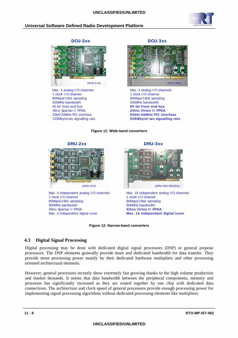
In figure 11. two wide-band converters are shown. The first converter is from the DCU-2xx product family, it has 4 channels and a 32bit PCI interface. Converter products in the DCU-3xx family can also process 4 channels, and are connected to the host system via a 64bit PCI interface.
In figure 12. two narrow-band converters are shown. The first converter is from the DRU-2xx product family, it has 4 channels and a 32bit PCI interface. Converter products in the DRU-3xx family may process up to 16 channels, and are connected to the host system via a 64bit PCI interface.
Universal Software Defined Radio Development Platform
11 - 8 RTO-MP-IST-062
UNCLASSIFIED/UNLIMITED
UNCLASSIFIED/UNLIMITED
DCUDCU--2xx2xx DCUDCU--3xx3xx
(DCU-214) (DCU-304)
Max. 4 Max. 4 analoganalog I/O channelsI/O channels1 clock I/O channel1 clock I/O channel80Msps/14bit sampling80Msps/14bit sampling500MHz bandwidth500MHz bandwidth40 bit front40 bit front--end busend busXilinxXilinx Spartan II FPGASpartan II FPGA32bit/33MHz PCI interface32bit/33MHz PCI interface133Mbyte/sec signalling rate133Mbyte/sec signalling rate
Max. 4 Max. 4 analoganalog I/O channelsI/O channels1 clock I/O channel1 clock I/O channel80Msps/14bit sampling80Msps/14bit sampling500MHz bandwidth500MHz bandwidth80 bit front80 bit front--end busend busXilinx VirtexXilinx Virtex II FPGAII FPGA64bit/66MHz PCI interface64bit/66MHz PCI interface528Mbyte/sec signalling rate528Mbyte/sec signalling rate
Figure 11: Wide-band converters
DRUDRU--2xx2xx DRUDRU--3xx3xx
(DRU-204) (DRU-304-FE16D1)
Max. 4 independent Max. 4 independent analoganalog I/O channelsI/O channels1 clock I/O channel1 clock I/O channel80Msps/14bit sampling80Msps/14bit sampling500MHz bandwidth500MHz bandwidthXilinxXilinx Spartan II FPGASpartan II FPGAMax. 4 independent digital tunerMax. 4 independent digital tuner
Max. 16 independent Max. 16 independent analoganalog I/O channelsI/O channels1 clock I/O channel1 clock I/O channel80Msps/14bit sampling80Msps/14bit sampling500MHz bandwidth500MHz bandwidthXilinx VirtexXilinx Virtex II FPGAII FPGAMax. 16 independent digital tunerMax. 16 independent digital tuner
Figure 12: Narrow-band converters
4.3 Digital Signal Processing Digital processing may be done with dedicated digital signal processors (DSP) or general propose processors. The DSP elements generally provide more and dedicated bandwidth for data transfer. They provide more processing power mainly by their dedicated hardware multipliers and other processing oriented architectural elements.
However, general processors recently show extremely fast growing thanks to the high volume production and market demands. It seems that data bandwidth between the peripheral components, memory and processor has significantly increased as they are routed together by one chip with dedicated data connections. The architecture and clock speed of general processors provide enough processing power for implementing signal processing algorithms without dedicated processing elements like multipliers.

Universal Software Defined Radio Development Platform
RTO-MP-IST-062 11 - 9
UNCLASSIFIED/UNLIMITED
UNCLASSIFIED/UNLIMITED
Figure 13: State of the art PC architecture [4]
On the other hand ready to use operating systems (OS) or even real-time operating systems (RTOS) are available for these processors with well-documented and well-supported software development tools. So we have decided to use latest Intel based architecture and processors (shown in figure 13.) as signal-processing element instead of dedicated DSPs.
Figure 14: Digital analysis
After choosing the PC as our working platform, we have developed for processing purposes some basic software including waveform generation and signal analysis as represented by the pictures in figure 14. As described at the principle of SDR technology, the success of the SDR is based on the published and open interface of the components. Our software is based on an application-programming interface (API) defined by us. Software modules and application developed by our team could be used as starting point to develop any other solution based on our hardware elements.

Universal Software Defined Radio Development Platform
11 - 10 RTO-MP-IST-062
UNCLASSIFIED/UNLIMITED
UNCLASSIFIED/UNLIMITED
5.0 EXAMPLES
In the following part of this document we will show some practical example implementations based on our SDR technology.
1-2500MHz
••11--2500MHz 2500MHz frequency rangefrequency range••1Hz resolution1Hz resolution••90dB dynamic range90dB dynamic range••AnalogAnalog modulationmodulation••Digital modulationsDigital modulations••Complex modulationsComplex modulations••BuiltBuilt--in modulation in modulation sourcessources
SGUSGU--2500 generator2500 generator
Figure 15: Modulation generator
The first case seen in figure 15. is a good example for complex waveform generation. This device can be used to generate modulated carriers from 1MHz up to 2500MHz with 1Hz resolution. The unique feature of this equipment is that it contains lot of modulation formats and sources called waveforms in the language of SDR technology. Simple analogue modulations like AM, FM, SSB, digital modulations like ASK, PSK, FSK and its variants, complex modulations up to 256 QAM and some other techniques like DSSS, FHSS, FDM, TDM could be used.
••SubSub--impulse impulse modulated TX burstmodulated TX burst••MatchedMatched--filter filter based compressing based compressing receiverreceiver••IF level signal IF level signal recordingrecording
SET-078 TG-046“Multi-Band Radar
for Air Defence Systems”
SRVSRV--P18 VHF radarP18 VHF radar
Figure 16: Burst of the radar application

Universal Software Defined Radio Development Platform
RTO-MP-IST-062 11 - 11
UNCLASSIFIED/UNLIMITED
UNCLASSIFIED/UNLIMITED
The next example is also a kind of waveform generation, but in this case we use the SDR technology and platform components to generate radar signals with sub-impulse modulation. As you may see from the screen shot of the signal processor (shown in figure 16.) the application is used for generating different kind of sub-pulse modulated BPSK bursts with some code content, linear and non-linear FM modulation. The signal processor of the receiver contains the matched filter based pulse compressor for these signals. This experimental radar system was used in the trial of SET-078 TG-46 too.
The two last examples show other type of usage of our SDR technology.
••Integrated Integrated fronfrontt--end end tunertuner••2020--3000MHz VUHF3000MHz VUHF••1.51.5--32MHz HF32MHz HF••300KHz IF bandwidth300KHz IF bandwidth••AM/FM/SSB/ISB AM/FM/SSB/ISB demodulationdemodulation••Hard disk recording Hard disk recording facilityfacility
SRMSRM--3000H receiver3000H receiver
Figure 17: Monitoring receiver
One of them is a monitoring receiver (shown in figure 17.) where the narrow-band converter is used for digitising the incoming 40MHz bandwidth limited from 1.5MHz to 32MHz HF band and forms a direct digital receiver (DDR) for that band. The monitoring receiver provides up to 300KHz instantaneous bandwidth for digitally implemented demodulators.
••40MHz instantaneous 40MHz instantaneous bandwidthbandwidth••1ms time resolution1ms time resolution••1KHz frequency 1KHz frequency resolutionresolution••1200/3200 pixel 1200/3200 pixel displaydisplay••Full or partial Full or partial bandwidth processingbandwidth processing
SRSSRS--3000H receiver3000H receiver
Figure 18: Scanning receiver

Universal Software Defined Radio Development Platform
11 - 12 RTO-MP-IST-062
UNCLASSIFIED/UNLIMITED
UNCLASSIFIED/UNLIMITED
The last example (shown in figure 18.) illustrates the usage of the wide-band converter to build a fast scanning panorama receiver. In that case the spectrum estimation is done by digital processing, and by using the Windows-based graphical interface it is possible to search a wide frequency range for signals. This kind of receiver can be integrated into a bigger spectrum management system.
6.0 CONCLUSION
In this document we have introduced the basic principles of the SDR, the technology that is the framework of future radio devices and system development. We have defined a basic model of radio devices based on SDR. Following that we have introduced a universal development hardware platform and its components. Finally we presented some example applications based on the previously mentioned hardware platform.
[1] http://www.sdrforum.org
[2] http://jtrs.army.mil
[3] http://jtrs.spawar.navy.mil/sca
[4] http://www.intel.com/products/chipsets/975x