the viscid flow of air in a narrow slot - magic naca...
TRANSCRIPT

MINISTRY OF SUPPLY
AERONAUTICAL RESEARCH COUNCIL
CURRENT PAPERS
The Viscid Flow of Air
in a Narrow Slot
G L. Shires
Crown CopyrIght Reserved
C.P. No.13 (12329)
A.R C. Technml Report
LONDON , HIS MAJESTY’S STATIONERY OFFICE
1950
Price 2s 6d net

mmorsndm NO. M.46.
December, 190.
The Vucld Flav of Air rn a Narrw Slot
- by -
G.L. Shires.
The propartzes sf the viscid flow of ar in a rectangular slot having a rndth large xn compar~on lath its depth are mnvestrgated. The results of' varuw tests cre found to verify thaaretioal and enpxrxal relatlonshrps between the pressure dxstrrbutlon in the slot, the au qass flow and tempera- ture, and the slat dimensions. Euth 1aruna.r and turbulent flows are con- s1dered.
CONTENTS
I .o Intra&u3t~cn
2.0 The Equations of Vlscld Flw 2
2.1 The TheoretxxilEquat.tlon for Lanruar Flow 2.2 The Empuxal3quatk~1 usu-~g the Resutvlce Coefficient : 2.3 Solutions for Thrct Partxular Cases 5
3.0 The ;ippwatus and the E'iethzd of Testug 7
4.0 The Aralysls af the Test Kisults 7
::; case 1. Constant Crass SEctxon Case 2. Constant Depth and Incressmg \i'ldth ii
L.3 Case 3. Constant Xdth and Increzslng Depth 9
5.0 Conclusions 10
List of Illustrataons IO
L3.st 9f Appendices 11
References II
Appendices I to IV
Figures 1 to 13
12 - 16
1 .o Introduction
The three foroes affecting the flaw 'of au in a slot are the pressure force, the force due to vlscoslty, md the force requrred. ta accelerate 3r deccelerate the flud. If, however, the depth of the slot is very sm-11, the vxad fxce and the p~%~-e force are very lar;t, and In oonparlsan the inertu farce 1s small enough to be no&ected. This bang so, the viscid force 1s equated to the pressure fwce and a simple theoretxal equation relatln& the pressure distribution, the ar temperature, the nass flow and the slot &rnensuxx is obtzuwd for steady 1amin.a.r flaw. To derive a sxular cquatl3n for turbulent flow the problem 1s considered in


Although the above analysis 1s concerned ,iith the pressure drop alow, ; narrwcc rectangular slot the exparmental results may also be expressed in tams of %ch number, !4. For thu purpose tke mean velocity bzsad on IY=SS flew,
G iii= - c.a.h , 1s taken as representative and values of ii calculated from the
expression -
E Id=-- G m-
-. p.a.h
Over the test length the i,&.ch nmbor was al-mys low and vlriatlons of temperature mre negligible. Hensti, ovc:c this sectron,
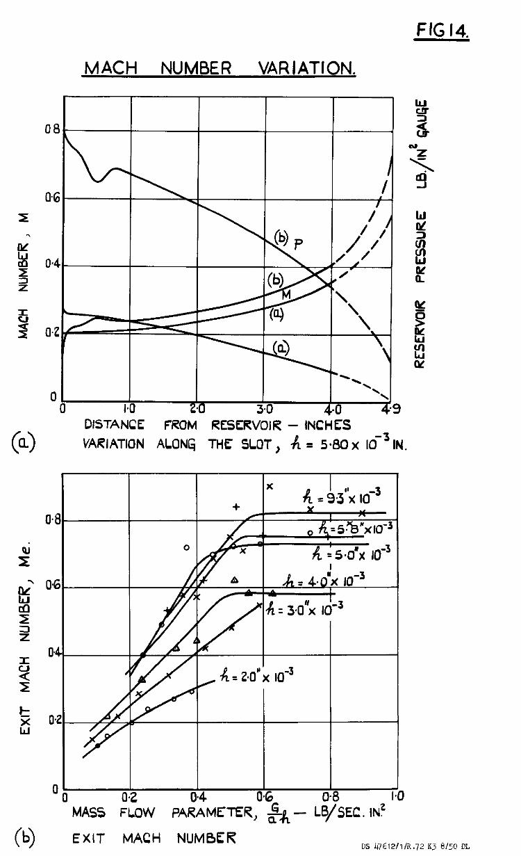
where To 1s the roscrvolr tmpperature. Typical curves of statw pressure, pa and Mach number, Xi&, over the test length of a parallel szded rectangular slot (case 1.) are shorn as full llnds 1x2 Fig. 14(a).
In the last inch of slot t‘nerc 1s a large drop in pressure and density and hence a rapid acceleration. In 'mm length the varmtion of teqerature cannot be neglected. If adlabatlc flmis assw& zn this part of the slot the exit mch numbm, &, can be calculated for case 1, frow equations glvcn by Kestin and 0ppenhem.W These can be rcducud to the expression:
where subscripts 1 and 2 denote two posltlons separated by a distance L. The reslstancc coefficient h 1s assumed to be the same all along the slot, since the Reynolds Number 1s constant , and Its valut: I.S caloulated f'ron! measurements in the test length. The calculation of the exrt Iwch number, &, 1s in effect an extrapolotlon of the ourves of Xach number in the test length with the assumption of adlabatlc expons~on ln the last Inch. Such axtrapolatlon is, of course, necessary since the prossure JUST u%?&e the slot exit 1s not always ntrospheric. Vhen the slot 1s choked it IX&Y be mu& higher as in case (b) in Fig. 14(a). Case (a) 1s unchd~ed.
When Me is plotted against the pass flow, Pig. 14(b), IC attains a constant value, not necessarily equal to unity, lndloatlng tht choking condltlons were reached, l~:lth the four larger clearances. The fact that it, does not become unity nr.y be due to It bung based on the seen velocity whereas the exit velocity profllz was probably not unifor;- and choking ?rabsbly occurred when the LJ~~XXILP voloc:ty reach-d the: local sonic value. If this 1s true then the apparent Xach nubur, if,, correspondlw to choking the exzt 1s effectlvcly a profile factor. The reduction of ths choking value of Pi, with decreasing clearance sows to indicate the truth of this assumption.
w J. Kestin, U.K. OppenheuL - "hi: Calculation of Comprcsslble Flurd Flow by thz Use of a Generalised Entropy Chart (Equations 17 and 65~1). - Inst. of Nech. Eng., Proc. 1948, vol. 159, Tar "Iimgancy Issue No. 43.
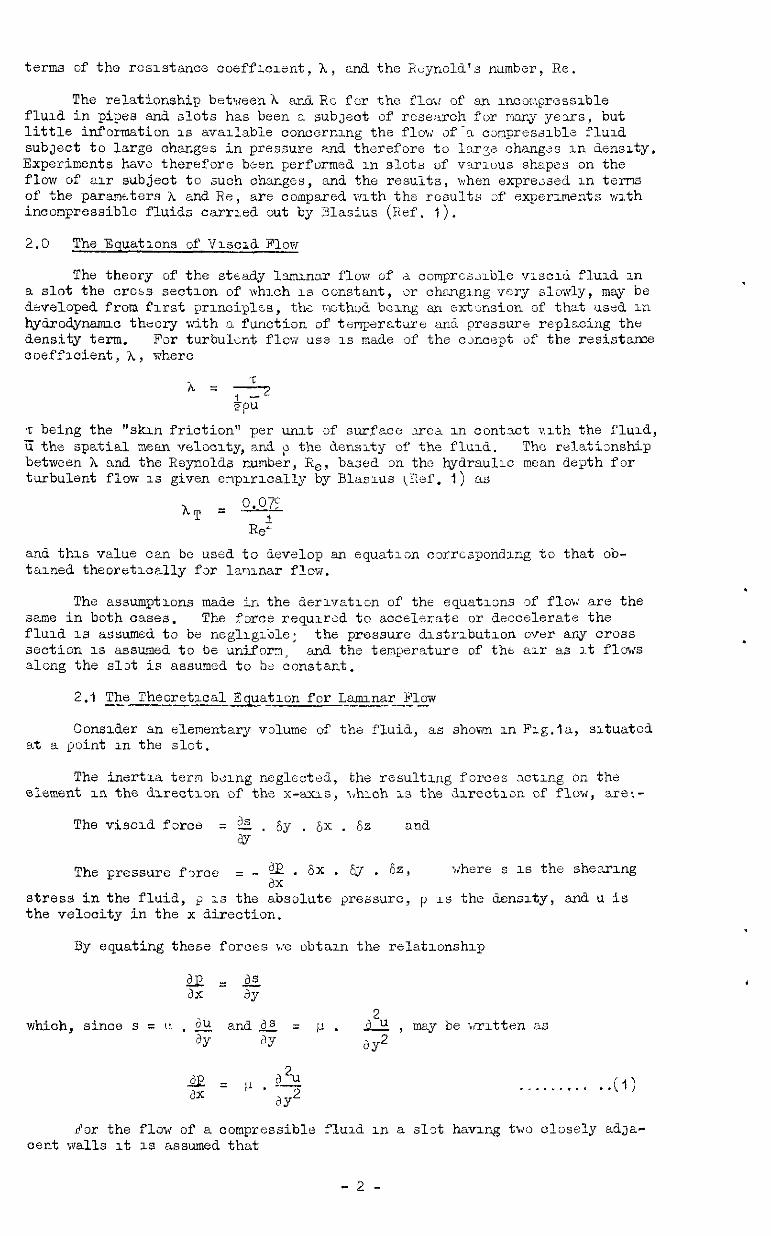
terms of the resistance ooeffx~ent, h, a-13 the R:cynold's number, Re.
The relationship betweenh and. Rc for the flo;i of an mncofi\presslble f'luld in pipes and slots has been a subjeot of research for marq yexs, but little information 1s wadable ooncern~-~g the flow &-a csmpresslble flud subject to large char.ges in pressure and therefore to 1ar-r~ changes III Censrty. Experiments have therefore been performed In slots of various shapes on the flow of air subject to such changes, and the results, -when expressed In terns of the paramtters A and Re, are compared with the results 3f experiments with incompressible fluids carrIea gut by Ylasius (Ref. 1).
2.0 The Equations of TIxxzd Flow
The theory of the steady lsnunar flow of d comprcs;~ble v~scd flurd In a slot the crabs section of whxh 1s constant, w changing wry slowly, may be developed from first prmnciplw, tk r&hod bezng an extension of that used in hydrodynamic theory with a function of temperature and pressure replacing the density term. For turbulent flow use IS made of the concept of the resistan% coeffv&ent, A, where
T being the "skin friction" per unit of surfzce xc& In oontlct slth the fluzd., < the spatial mean velocxty, and p the densrty of the f1uz.d. The ralatisnship between h and the Reynolds number, Re, based in the bydraulx mean depth for turbulent flow 1s given enp~rxally by Blas~~s (Ref. 1) as
and. this value can be used to develop sz~ equatlx corresponding to that ob- tax& theoretwally fsr la~nar flow.
The assumptions made in the derlvatlon of the equatwns of flaw are the same in both cases. The farce requxxd to accelerate or deccclerato the flud 1s assumed to be negl:llglble; the pressure dxdrlbutlon over s.ni cross section is assumed to be unif'on, and. the temperature of tht air as It flows along the slst is assumed to bs constant.
2.1 The TheoretxcalEatlon for Larmnar Flow -- --____ _---- --- --
Consder an elementary volume of the fluid, as shown m Flg.la, sltuated at a point In the slot.
The inertia tern b*lng neglect&, the resultxng forces nctwg on the element m the dlrectlon of the x--s, l"hich 1s the &xectxsn of flow, are:-
The vised force : &Z . by . 6x . 6z and ay
The pressure fx-ce = - g . 6X . 6;1 . 6e, where s 1s the shearing
stress in the fluid, r, 1s the absolute pressure, p 1s the denszty, ancl u is the velocity in the x direction.
By equating these forces i.'e obtan the relatlonshlp
which, since s = I? . & anadS = p. & , may be written as 3Y ay a9
. l . . “ “ . . . ..(I)
dor the flow of a compressible fluid III a sld hamng two closely adja- cent walls It 1s assumed that
-2-
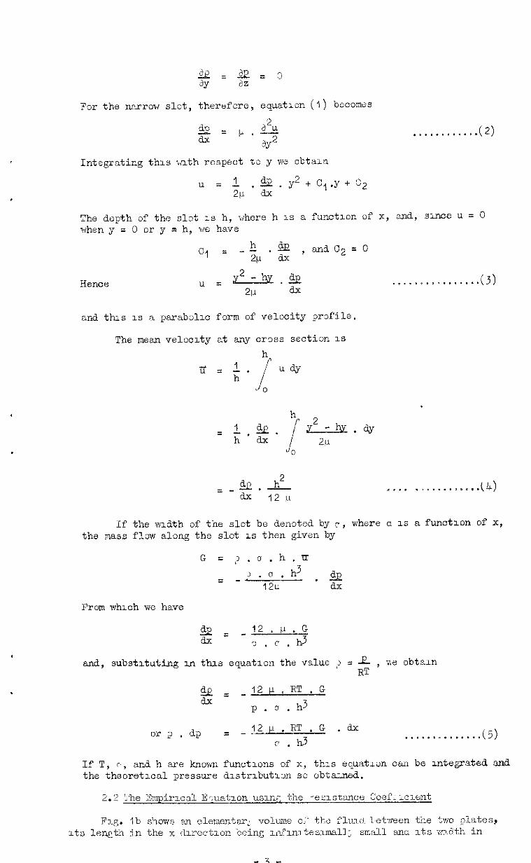
For the niz~row slot, therefore, cquatmn (1) becomes
iE?=,.i.s 8.x 3Y2
Integrating this iilth respect to y we obtain
.*...**...*. (2)
u = L & . y* + c, .Y + s:2 2p * a.x
The depth of the slot 1s h, v/here h 1s a fun&Ion of X, &, 3me U = 0 when y = 0 or y pi h, we have
Cl = h
--& .a
dx ' and c* = 0
. . . . . ~ *. . . . . . . . .(3)
and this 1s a parabolx form of velocity profile.
The mean velocity at any CI‘DSS sectim 1s h
1 iy = -.
/ u@
h j 0
h 1 2.E.
= h'ax s
y2.aY 2li
0
= - 92 .A?- **.. . . . . . . . . . ...(4) ax 12 P
If the mdth of the slot be denoted by r, where a 1s a functmn of X, the mass flow along the slot LS then given by
G = ?.o.h.u 3 .". h3 = -
12c
& = -12.v.G dx ', . c . d
and, substituting m thzs equation the vslue ;' : 1 , v<e obtam RT
c& = -121-1.RT.G ax
p.a.h3
or 2 . dp = -?2p.KT.G .dx 0
. . . . . . ~ . . . . . . . (5) c .
If T, c', and h are known fun&mm of x, th-s equation can be mtegmted and the theoretmal pressure dmtrlbutlm so obtaaad.
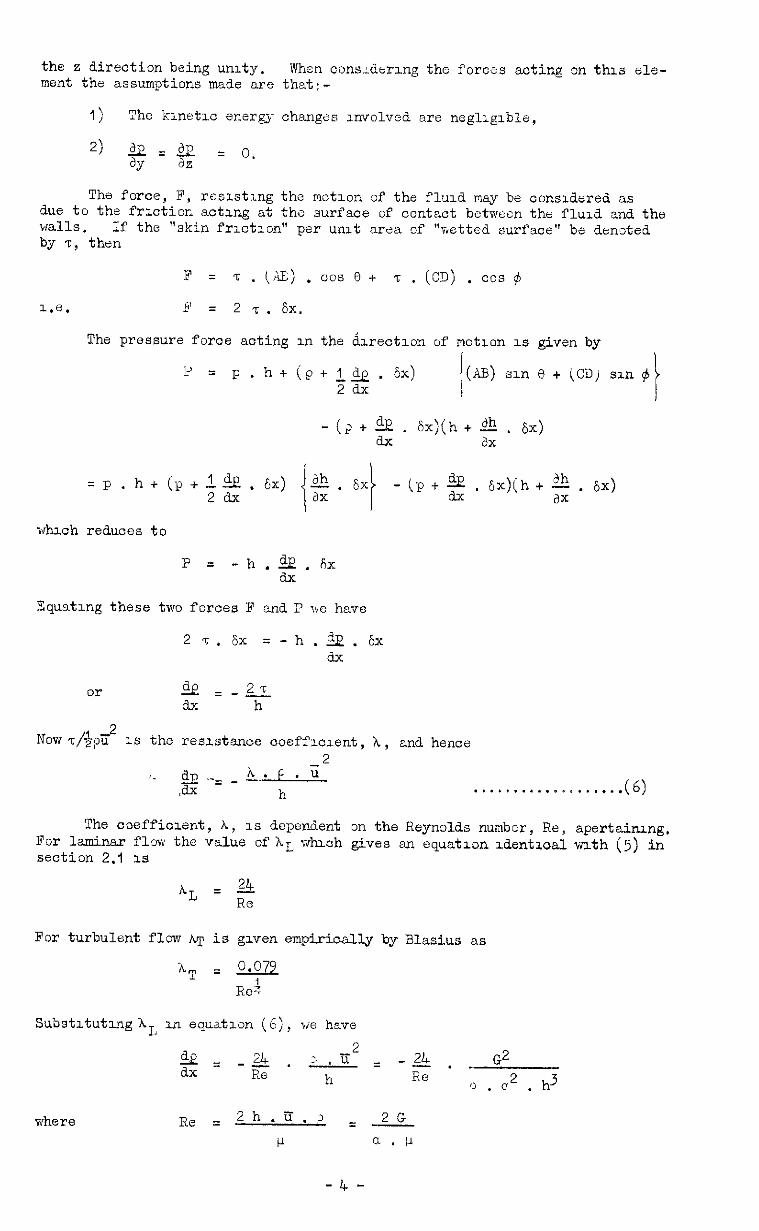
the z direction being umty. When cons:dermg the ment the assumptions made are that:-
forces acting on this ele-
1) The kmetlc energy changas uv~~lvsd are negllglble,
2) &=a = 0. ay dz
The force, F, rcslstmg the motun of' the flud may be consdared ns due to the f'rlctior, acting &t the surface of contact between the flud and the w.lls. If the "skin frlctlon" per unit area of "wetted surface" be denoted by 7, then
F = 7 . (AE) . DOS 8 + 7 . (CD) . cos 6
I.e. P = 27.6x.
The pressure force acting m the &e&Ion of motxon 1s given by
'u = p. h+(p+l&.&) I (AB) sin @ + (C3,i an $ zax
- (> + ii? . 6x)(h + dh . 6~) ax ax
=p. h + (P + 5 2 . cx) - iP + g . &x)jh+ $ . 6~)
whxh reduces to
P = -h.&.fix ax
Equating these two forces F and P Tye have
2 7. 6x =-h.&.Sx ax
or &= 27 -- ax h
Now T/$$ 1s the resdxmce coeffux.ent, h, and hence 2
I_ c&.-=-h'k * u ,dx h . . . . e ,.... ~ . . . . . . . . (6)
The coeffiolent, A, 1s dependent on the Reynolds number, Re, apertainug. For laminar flw the value ofh~ v&ah gives an equattlon da.tloal t-ulth (5) in section 2.1 1s
For turbulent flow Q is given empiriully by Blasius as
SubstltutughL u equatitlon (6), we have
g= -2. -,= -3. G2
h Re ,, 2 3 .c .h
where

or P . dP = - 12 p.RT.G.dx c . d
whxh IS the same as equation (5).
To obtarn the correspondug equatxon f3r turbulent flow we substitute rn equation (6) the value of $.
2 +p=-~.~= Rei
-0.079. G2 h 1 ReL p . a2 . d
7
0 067 pt. G i; = - I
I h3. a4 .p
I!
or p . ap = _ 0.067 p’ . RT . G4 . & 7 . . . . . . . . . . . . . . ...(7)
a;: . d
2.3 Solutions fpr Three Partz~cular Cases -- .--"-----
The general equatrons, (5) ad (7), can be integrated lf o, h, and T are kncwn as functions of x. For the three types of slat dlustrated in Fig. 2 the mtegratmns have been performed on the asswmptlon that the temperature, T, 1s cxxtant along the slot.
Case I, a mnd h oonstant --- ----. ---_
The lntegratlon of equation (5) gives in this case the fdllowing result for steadjr lamu~~r flow.
p2 = x . . . . . . . . . . . .(3)
2 or Pq - P22 =.Z~IJ .RT . G(+ -x1)
h3 . . . . ..*...... (5)
0 .
On lntegratlng equation (7), we obtain for turbulent flow
73 EC constant - . . . . . . . . (IO)
Case 2. h constant and a= cx x -_-_ ----.-p--f-_
If the frIctiona effect of the two side walls 1s negleoted, the flow -in this case 1s analogous to the r&al flow between two wLfx%Ly spaced circular flat plates and by symmetry the pressure at any radius 1s cons'csxt.
-5-

ProvxM., therefore, that the tivergence 1s small the pressure in any plane perpendmular to the axis 1s approxmately constant and equatmns (5) and (7) may be applied. larmnar flow
By substituting in these equstlons & = o( .s, w obtazn for
p,ap = -12p.RT.G. e cx . h3 x
whxh when integrated becomes
P2 = constant - i
24 u .RT . G . lo& x
q . h3 > . . . . . . . . . . (12)
or PI 2 - P22 = 24 u . RT . G . log, x2 h3 T-
. ..*......*....... (13) o(.
and., for turbulent fla7, I
P. ap = - 0.067 y: . RT . G' . &
1 ct.4 . h3
1 x4
which when integrated becomes I
p2 = constant + 0.178 P’ . R’P . G4 . 1
i
. . . . . . . . ..a.. z
i I
(14)
GC4 .h3 x4
Case 3. Constant kdth and. Inoreaslw Depth
As the deviation 3f the two plane surfaces is very small, the components of velocity perpendicular to tht ax~ of the slot must also be very small, and the pressure distribution zver any cross sectlsn x,therefore, assumed to be dorm.
For laminar flsw, by substituting h = p . x in equation (5), we abtam
P * dp = _ 121-1.RT.G . &
@ .P 3 x3
and %ghen integrated thus becomes
p* = constant + '2 p 6 RT * G . 1 i \ a.!3 3 x2
. . . . . . . . . . . . . . . . . ..(16)
or PI 2 -p22 = 12i-1.W.G 3 . . . . . . . ..*............ (t7)
a - B By the same substitution in equation (7) we have, for turbulent flow,
dp = - 9.067 p' . RT , t P . G . +
1 3 3
04 * p
vkch when integrated gives
p* = ,..*,...*.*...* (18)
-6-

0.067 cl; 1
or PI
2
.RT.G 8, - p*2 = A- I 1 1 x1 2
xz2 I .*............ 119)
04 . p 3
The a~p~aratus, as shm,n m Fly. 3, consisted essentially of two fl2t steal plst'3s sepwated by thin strips sf st2e1 arranged so as t3 form a passage of the required. shape. The two plates uutire made I" thick to prevent
8 any appreciable bchdlng, ana, after the upper one hd b?en case h~dencd, the surfaces forming the hvrleonta.1 iinlls of the slot were carefully ground and tested against an optical "flat". The m~.~mnun denatum fron the plane, as estimated by cxntlng the lnterfzrenoe fringes, was about 50 , 10-6 inches. Between the tws plates the sl;t *,ns bouded Qn each 31de by strips of steel, whxh In the case 3f the slots sf constant depth wre of single thickness but which far slots of vnryzng depth were overlapped In the form 3f steps. i;'hen the blzck was nsstmbled and firmljr clamped togtther a szallng conpoUd was applld uxternelly ta -11 the jomnts.
During the t&.sts cx-presxd nlr nt z recorded tempedxrre, T, passed through a wtcrlng scctlon and lnt- t'he sharp edged rectangular rtservoir 1n the upper plate. From there It flowd along the rectangular passaga between the two plates tc atmosphere, the stdx pressure being recorded at intervals of :I" docg ths 1x1s. A line of 7 grLssure tlpplngs across the slot at right angles to the 2x1s was use& 2s a check upon the setting of the block, since any ;nclir,atlon rf the tv3 surfaces In a plane perpendicular to the axis would rtsult in 2~1 ~ssyrrwtrxs.1 pressure tistrlbutlon over these 7 pslnts. The pressure dlstrxbutxn at this cross sectron was found to be umforn as nssuned m the thecry.
The procedure for a<ach test -da3 the same and cznsrsted of two parts. Th6 first %ras the recwding of the xlal pressure dxtribution for VwlOus values zf the reservoz pressure, po, and the anjlysrs sf these results. It was lnverxbly found that the prxs-sure dxtrlbution avtir the central 3" length sf slat cudxmtd t3 thz correspstilng theoretical form and thd this length could be cx~s~Lred as a sultsble ta:st length. The second part of the procedure involved ,-n xwzstlgatlon of the rilat.tlxxhip between the a~ mass fl<w, G, in the slot and the prtssures p, and p2, where p, denotes the pressure at the upstream end <and p2 the pr-essure at the downstrean end of the test length.
4.0 The hnalysls of the Test Rcsdts
The aim of thz tc;ts r>as to check the valdity of the formulae dzvel0ped u? sectrons 2.1 and 2.2, and, T-here pzsslble, to aetermlne tht relationship betmew the reslstnnce cdtfficlent, A, and the Reyngld's number, Re. SlnGC the cquati,,ns Involve both thz wzdth, a, and the depth, h, as varrables, It was necessm~y '1s an overall check t3 use thrte types of sld, one with il constant crass se&Ion, one with a varying width, and. one rslth a varying depth. Equations (8) to (19) a;j-ply to the thrcu types of slst used and are coripared in thi f'Jlc~J,mg pages with the test results obtained.
L.1 Case 1. Constmt Cross Section -
Tests wre 'wdde with six slots havlng 2 w&h, n, of 1.75" and a depth, h, of approximately O.OOZO", C.OOjO", 0.3040", 0.0050", 0.0058", and O.OC93".
Fig. 4 shws the axial pressure tistrdutlons as recorded for two 2 the slots, the dlstrlbutlons obtalnzd with the uthw four slots bexng of the same form. ilhen the square of the absolute pressure, ~2, is plotted agam.st the axial drstance, x, a series 3f straight lines are obtained. aver the central 3 ' length of the slot, the f'wm of the theoretxal rcls.t.tlsnshlp bstween p znd x bt.lng thus vcnfxd.
The slope df each of these straight lines ,(PLz 1 "," j , is a measure
of the rcslstance to flaw and is plstted l~garlthdcall~- ngalnst the OOFXS- POmhI& mnss flm, G, in Fig. 5. Here, the SIX curves represent the results
-7-

far the six slots investi&trd and, SUT.X mtslde the transltlnn z3nt each set of results oar, be represented by two straight lines, the relationship between the pressure drep and the mass flow is c&arly of the form
PI2 - P22 = Constant . G" . X2 - X1
The constant in this equation is different for laminar and for turbulent flow as is also the index n, which for larunar flow is 1.0 and for turbulent approximately 1.75. The non-linear part of the curve represents the transi- tion from laminar to turbulent flow.
The experimental results s.r~ also shown as pJint,s in Fig. 6, together with the theoretical curves obtained by substituting in equations (8) and. (Ii) the slot dimensions and the air temptirature. The difference b&wean the corresponding calculated and measured values 3f [P12 - p22j as a percentage
less t where h = O.OOjC'
\ x2 - x, / of the measured value, is with one exccptron less than $ for 1armns.r flow and
hen 1% for turbulent flow. The larger overall discrepancy in the case " is probably due to a small error in the measurement ,~f h.
To complete the picture a graph is given in Pig. 7 of the resistance coefficient, A, against the Rsynold's number, Ra, where h and Re are calculated according to the equations derived in Appendix II. For laminnr flow the points lie on the theoretical curv,,, XT> = ?L!L , but for turbulent flor-J the
0.079 lie
empirical expression, hT = ._ , as stc-hod by Blasius gives values of the Em;
resistance coefficient Lswr than those calculated from the test results. The experimental points for turbulent flow lie close to tho two curves, hTsyandhTs?ip,
Rez th,: first fitting the results for h = 0.0033" and
ReZ the second the results for h = 0.0058" snd h = 3.0040". Except for the case where h = 0.0050", the results indicate that the smalltr the value of h the closer lie the points to the e?prricni ourvz,hT = q .
ReT The tranmtion from laminar to turbulent flow takes place over a range
of Re wh-uhich is slightly different for each slot. These ranges are given in Appendix III, the average values of Re at the beginning and at the end of transition being 2,120 md 3,810.
4.2 Case 2. Constant Depth end Increasing ?idth
Two slots were used, each having n constant depth, h, and an increasing width given by n = (;( . x. The drpth in each case was O.C036", and the values of awere 0.1 and. 0.2.
The axial pressure distributions are shown in Fig. 8. The analysis reveals that these are of the form
and
p2 = A-B.log,x f3r lcaminar flow
p2 = C+D.i for turbulent flow.
2
A, a, C, and D are constants, and x is the axial distance from the imaginary pslnt of intersection of the two side walls. In this ease the analysis is nat SJ accurate as for case 1 and, although a strazghht line is obtained by plotting p2 against x-0.75, this figure cannot be taken as exact since a sin=- lzr straight line may be obtained by plotting p2 against x", where n rs.ng-3~ fron 0.70 to 0.80. The slight scatter due to errors in the rea&ngs of p is sufficient to mask the small deviations from the linear obtained with the varia- tion of n over this range.
In the first G" of slot length there was an appreciable divergence from
-8-
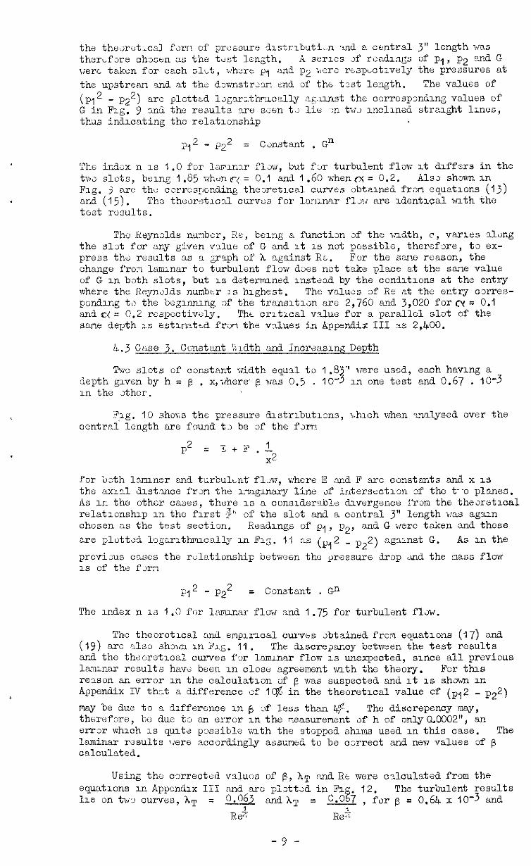
the thexotxal fern of pr ussure distributi-n and a central 3” length was therfore chosen as the test length. A 5631'1es 3f rsd.1ngs of p,, p2 ^ end. G were taken for each z&t, whore p, and p2 :>ers rtspLotively the pressures at the upstraar. and at the dswnstrear, end of the test length. The values of (~1~ - ~2~) are plotttd l~garrthr?lcelly ag3.mst the corresponding values of' G in Fig. 9 and the results are sax tz lie m tv3 inclined straight lmcs, thus indicating the relationship
p,2 - gz2 = Can&ant . G;"
The index n is 1.0 for larlnar flaw, but ftir turbulent flow it dlf'fers in the tw slots, being 1.85 vihc:n(r( = 0.1 and 1.60 xhhenrx = 0.2. Alss shorn in Fig. 3 arc thi: corresponding thesretical curves obtained frsn equat.tlons (13) aId (15). The thaor&xal curves for lapnnar flow are ldentxal >ath the teat results.
The Reynolds nunbcr, Re, being a function of the ,ndth, c, varies along the slot for any given value of G and it 1s not possible, therefore, to ex- press thr? results as a graph of h against RL. For the sarxe reason, the change from lanunar to turbulent flow does not take place at the sar~1e value of G in both slots, but is determined instead by the conditions at the entry where the Keyn~1d.s nunbr;r is highest. The valws of Re at the entry corres- pondlng ta the beginning of the transitian are 2,760 <and. 3,020 form = 0.1 andc:(= 0.2 respectively. Tht critxal value for a parallel slot of the sane depth is estlrlattd frori the values in Appendix III as 2,400.
4.3 Case 3. Constant %',rdth and Incrznsing Depth
Two slots of constant width equal to 1.8 ' were used, each having a depth given by h = fi . x,xhere' e was 0.5 . IO- 3 in one test and. 0.67 . IO-3 1.n the Jther.
FFg. 10 shoxs the pressure tistributxns, u.hich when analysed over the central length nre found t3 be of the fx~
p2 = x+02
for both lxuner and turbuL.nt fl>w, where E and F are constants and x is the axial dastvlce frdjn the ~xagmary line of intersection of the t--o planes. As in the other cases, there is a considerablz divergence fron the thexetxal relationship in the first $', of the slot and a contra1 3" length was again chosen as the test section. Readings of pi, p2, and G were taken and these are plot&d logarlthrncally m Fig. 11 as (p ,2 _ p22) against G. As in the previxs oases the rtilationship between the pressure drop md the nass flow 1s of thr3 fxn
i-q2 - P*2 = Constant . Gn
The index n is 1.0 for 1,mma.r flow and 1.75 for turbulent flaw.
The theoretical Land empiracal ourvos obtained from equations (17) and (19) are also shown ~.n Fig. 11. The d.xwre~anoy between the test results and the theoretIca curves fur laxlnar flow is unexpected., since all previous lsmumr results have been in close agreement snth the theory. For this reason an error in the calculation of e was suspected and it is shown in Appendix IV that a difference of la;?. in the theoretrcal value of (p,2 _ ~22) rwy be duo to a difference In lj of less than 49. The discrepency rosy, therefore, be due to an error in the measurement 3f h of onlyQ.C0J2", an error which IS quite possible wath the stopped shims used in this case. The laminar rssults 'iere accordingly assumed to be correct and new values of p calculated.
Using the correotzd values of @, hT cand Rt were calculated from the equatxons in Appendix III and arc plstt-d in FF~. The turbulent results 1~ on ix3 fumes, AT = q and AT = && :2ior p = 0.64 x iO-3 and
Rex ReS
-9 -

c = 0.49 x 10⁻³ respa3avely. It appezrs that the constant (XT , Rei) nay be dependent upm the sld divergence and sz It 1s plAted agamst I: m Q. 13. than 0.006"
Since the nean &pth 3f the tw slots used.,m this case was less (see section 4.l.j, the value of (AT . R&) cxrdspmding to
e = 0 (Case 1.) wz.a taken as 0.081. F1.g:. 13 shms that the three pomts lie apprximtely m a straight lme, thus mdmattlng a possible relatmn- ship bttweenhT, Re, and [ of the fxm
hT = 0.81 - 28 p
Rei
However, further tests ml1 be necessary to vbrd'y thus hypothesis.
5.0 Conclusions
The cmparison 3f the ti-st results vxth the correspmcling theoretxal and empmical relatlonshlps shows that these relatlonshrps hold apprsximately fx the flm 3f air ux ,md nammv alot, pmvlded that the &vergence 1s mall and that the length consderod do, us mt lx wlthm about 2" 3f the slzt entry x the slzt txit. \:lth these prxisims the fxces &ue ta the changes in kinetic energy are negligible. so that the r.ssumpt~sn mde m developmg the thexy 1s valid.
The results also mdicatz that thi fhcxeticsl equations my be used t3 give an ,mcurate qumtltatlve discrlptlon uf lamnar flaw. The only serious discrepancy bitwen the themy md the test results was in the case 3f the slots with mcrdasing d.tpth rind here the error was assumed to be m the masurement of the dlv&rgmct.
Fx turbulent flow th= enplrical rilatlonshl B r
sOpxd m the value of the msistance crxfflclent g~vm sy alnsms, hT = A ,
R& are nd m general
applicable. The investlgatlm shows that for slots of c,nstmt cross siction the actual value ofhT 1s lnrger, bemg 0.087 for the slot 3f depth
h = 0 0093" and 2-q for h = C 0058" Ro+
. * . Far s1As 2f xxcreaslng depth the
product (AT . ,ReZ
Re") appears tu be z constant, thL value Llf whxh depends upon the rate af divergence, fi, zf the mlls.
Llbt 3f Illustrntlms -
V~scld Flsv Thedry.
The Tj-:>es of SlA Cmsdered.
The T'dst Black.
Fressurc Dmtrdmtlon m the Slot (Case 1).
Effect 3f Pressure Drop on Mass Flm (Case I).
Conparmon with Theory. (Case 1).
Scde Effect in Case 1.
Pressure Dlstrlbution m the Slst (Case 2).
Effect af Pressure i~rap on siass Flow (Case 2).
Pressure Dlstrlbutlon =n the Slot (Case 3).
Effect of Pressure Drop anMass Flow (Case 3).
Scale Effect m Case 3.
The Effect of Slot Dlvur~ence.
Mach Number Varratlon
- 10 -

ik!lsranaum No. M.46.
List af Append~es
Appendix I Lrst of Synbols Used.
Appendix II The Calculatrsn sf h and Re.
Appendix III Trarmtion Values of Re.
Appen&x IV The Effect of Ermrs in the Neasurement of @.
Refzrcnces
Jg. Author Title
1. N.A.V. Piercy Aerodynamics : pp. 278; E.U.P.: 1937.
-11 -
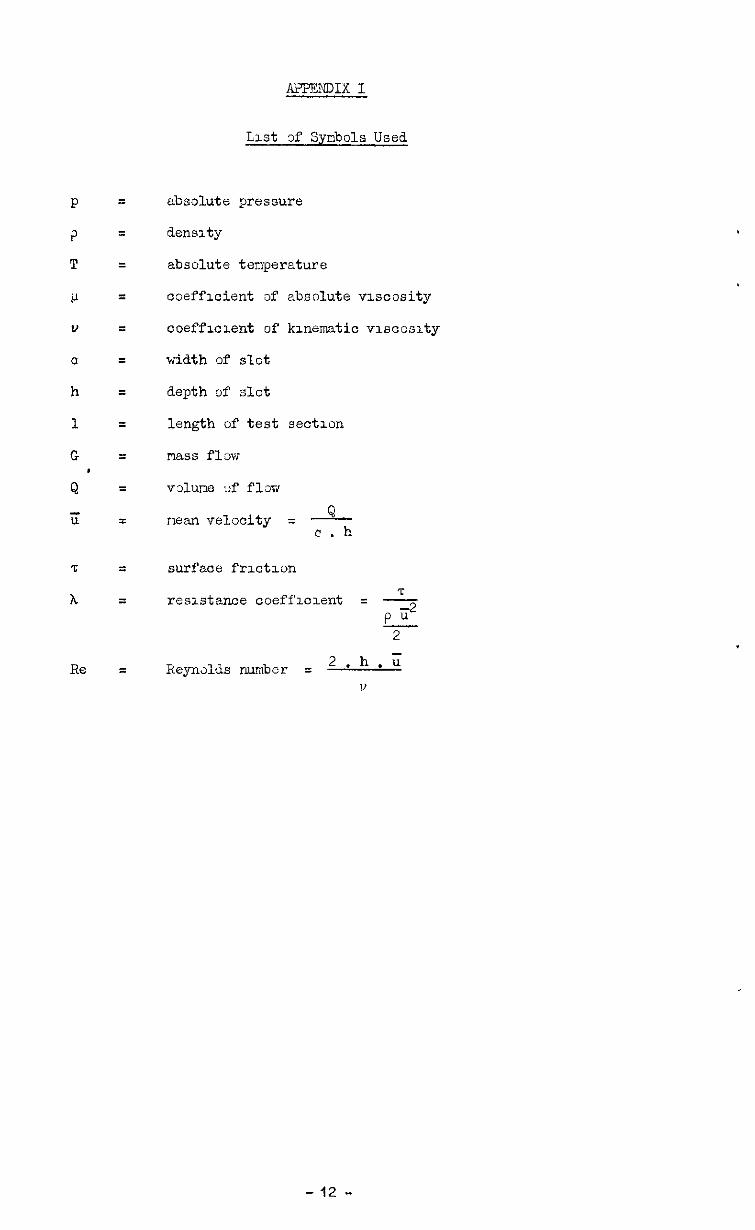
mm1x I
List 3f SyriDols Used
P = absolute pressure
P = aens1ty
T = zbsolute tenperature
!J = coefficient af absolute viscosity
v = ooefflclent of kmemtic vmcoslty
a = width of slot
h = depth of slot
I. = length of test sectmn
G = Ilass flaw
Q = valne I?f flow
ii = man velocity = -Q- c . h
z = surface frxtmn
h = T reslstanm coeffloxnt = - p ii2 2
Re = Reyndds number = 2 .h .u 11
- 12 -
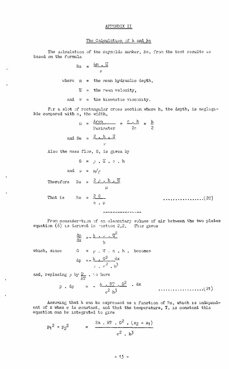
AP?ENDIX II
The odculztlun of the Rejwdds: nuiioer, Re, frzil the test results 1s based on the formula
Re = 4m.c v
where m = the mean hydraulx depth,
ii = the wan velncity,
and. v = the klnematw vlwx'slty.
Fx a slot af rectangular cross section where h, the depth, is negl~gl- ble compared with a, the width,
Therefore Re = =.h.ii
P
That is Re = ?s-. . . . . . ..*....*..*m (20) fi . P
Fran oonsderdlx af on ele;ler;tary volume of air between the two plates equatix (6) 1s dw~ved irk .sotmn 2.2. This g~vos
whxh, since G = p L Li , a . h , bccomzs
fip =-A . G 2 dx
J . n 2 . h3
and, replacing ;l by $ , : e have
p.ap = - h . RT ~ G2 . dx
c2 h3 . . . . . . ..‘..-....... t 21)
kssum~ny that h can be expressed as a function of Re, whuh 1s udepcnd- eat of x when CI is constant, and that the temperature, T, LS constant this equation can be u&grated to give
P,2-P$ = 2h . R'I' . G2 . (x2 - x,)
a2 . d
- 13 -

ma hence
2 h = PI - P22 c2 h3
x2 - 7 2 RT . G2 . . . . . . . . . . . ..(22)
For case 3, zn which the aepth of the sL3t 1~ zncreasing, we cm obtan a carrespondmg equation for A by substduting h = CCC in equation (21) and by integratmg.
This is p , dp = - A. RT , G2 . &
2 63 x3
ana P12 - P*2 = A. RT . G2 (1 -2 2)
a2 p3 Xl 2
x2
. . . . o . . , , , . . . . . . . * (23)
- II+ -
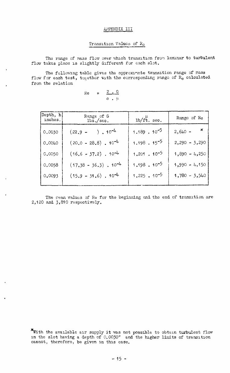
Ax?ENDIX III
Transltmn V'alucs of RC
The range of m.sa flm over whmh trans~tmn fro?; lznunar to turbulent flm takes place 1s slightly ddferent far each slzt.
The followmg table gives the approxlnate transition range af nnss flm far each test, tqether mth the correspon?ang range of Re czlculated fron the relation
Range of G lbs ./set.
(22.9 - ) . 10-4
(20.0 - 28.8) . 10'4
(16.6 - 37.2) , IO-4
(17.38 - 36.3) . 1O-4
(15.9 - 31.6) , IO-4
lb/ft. sec. Range d' Re
1.189 . lO-5 2,640 - *
1.198 . 15-5 2,290 - 3,290
1.201 . 10-5 1,890 - 4,250
1.198 . lo-5 1,990 - 4,150
1.225 . IO-5 I.780 - 3,540
-/
The cean values of Ke for the beginning m-13 the end of transrtion are 2,120 and 3,810 respectively.
%ith th e available au supply it was not possible t'3 obtam turbulent flow in the slot having a depth of 0.0030" and the higher limits of transltzon cannot, therefore, be given XI this case.
-15 -
APTNDIX Iv
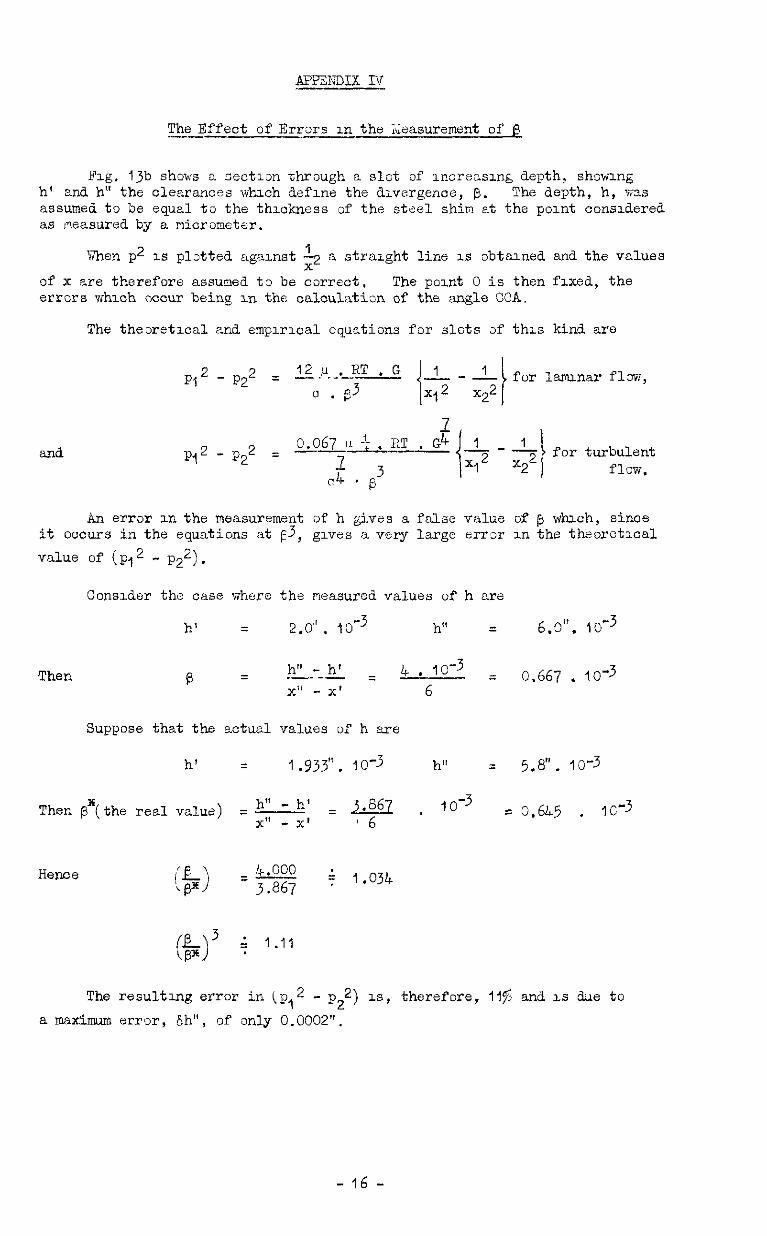
The Effect of Errxs m the Measurement of 8 ---
Fig. Ijb shows n se&Ion through a slot of ~ncreusm& depth, shomng h' end h" the clearances vvhxh aefme the dlvergenoe, @. The depth, h, ~3s assumed to be equel tu the thmkness of the steel shin at the pomt consdered as measured by a micrometer.
When p2 1s plA3xd agamst $ a straight line IS obtund and the values
of x are therefore assumed. t3 be correct. The pod 0 is then flxed, the errors vJhhlch ocmm being m the oalculatim of the angle GOA.
The theoretxal ti empmxal equstims for slots 3f th1.s Hnd are
PI2 - P2 2 = 12.!~.-.2T 0 . p3
and pq2-p22 0.067 ,I ET . G4 = --3
-‘; . for turbulent 04 3 flow, ’
6
An error m the measurement of h gives a false value of @ whxh, since it occurs in the equations at f3, gives a very large error m the theoretxal value of (pq2 - Pan).
Consider the case Tfhehere the measured values of h cre
h' = 2.0". lo-3 h" = 6.0". lO-3
Then 0.667 . 103
Suppose that the actual values of h are
h' = 1.933”. 10-3 h" = 5.8". lo-3
Then P*(the real value) = h" - h' =J.667. 10-3 x1' - x' 6
- 0.6L5 . IC-3
The resulting error in (p,2 - p,2) IS, therefore, 11% and. LS due to a maximum error, Sh", of only 0.0002".
- 16 -

FIG. I.
VISCID FLOW THEORY.
(4 ELEMENTARY VOLUME OF FLUID
x
(b) ELEMENTARY VOLUME BfTWEEN TWO PLATES
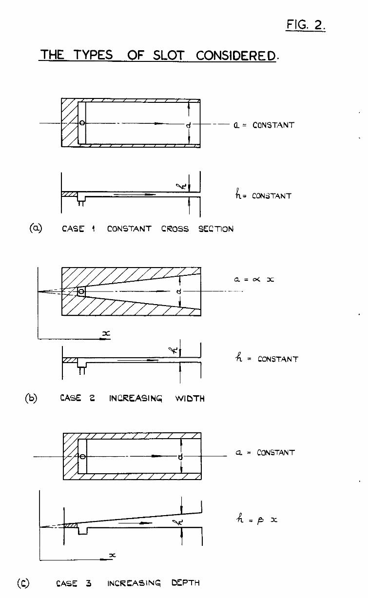
FIG. 2.
THE TYPES OF SLOT CONSIDERED.
-- (L = CONSTANT
(4 CASE 4 CONSTANT CROSS SECTION
a=d x
A= CONSTANT
(b> CASE 2 IN CREASI NG WIDTH
Q = CONSTANT
I I
k--k ‘rL = p
03 CASE 3 INCREASING DfpTH
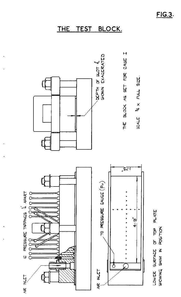
FIG.3.
THE TEST BLOCK.
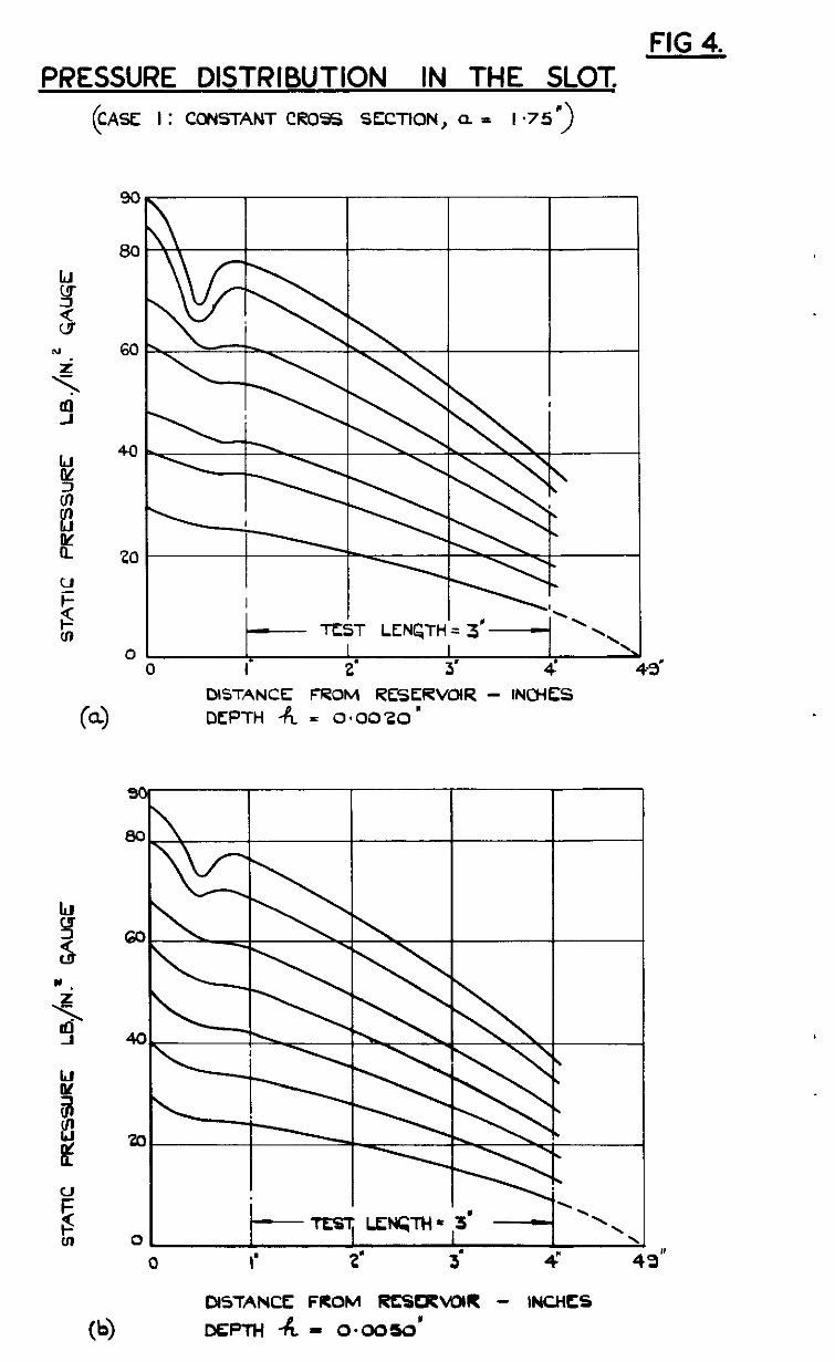
FIG 4. PRESSURE DISTRIBUTION IN THE SLOT
( CASE I : CONSTANT CROSS SECTION, a. = I .75”)
60
01 I I I I 0 I 2' 3’ 4 43’
DLSTANCE; FROM RRLRVOIR - INCHfZS
Ccl) DEPTH -R = 0~0020’
(‘4 DISTANCE FROM m=VUlR - INCHfS
DfPlH-R - 0amo’
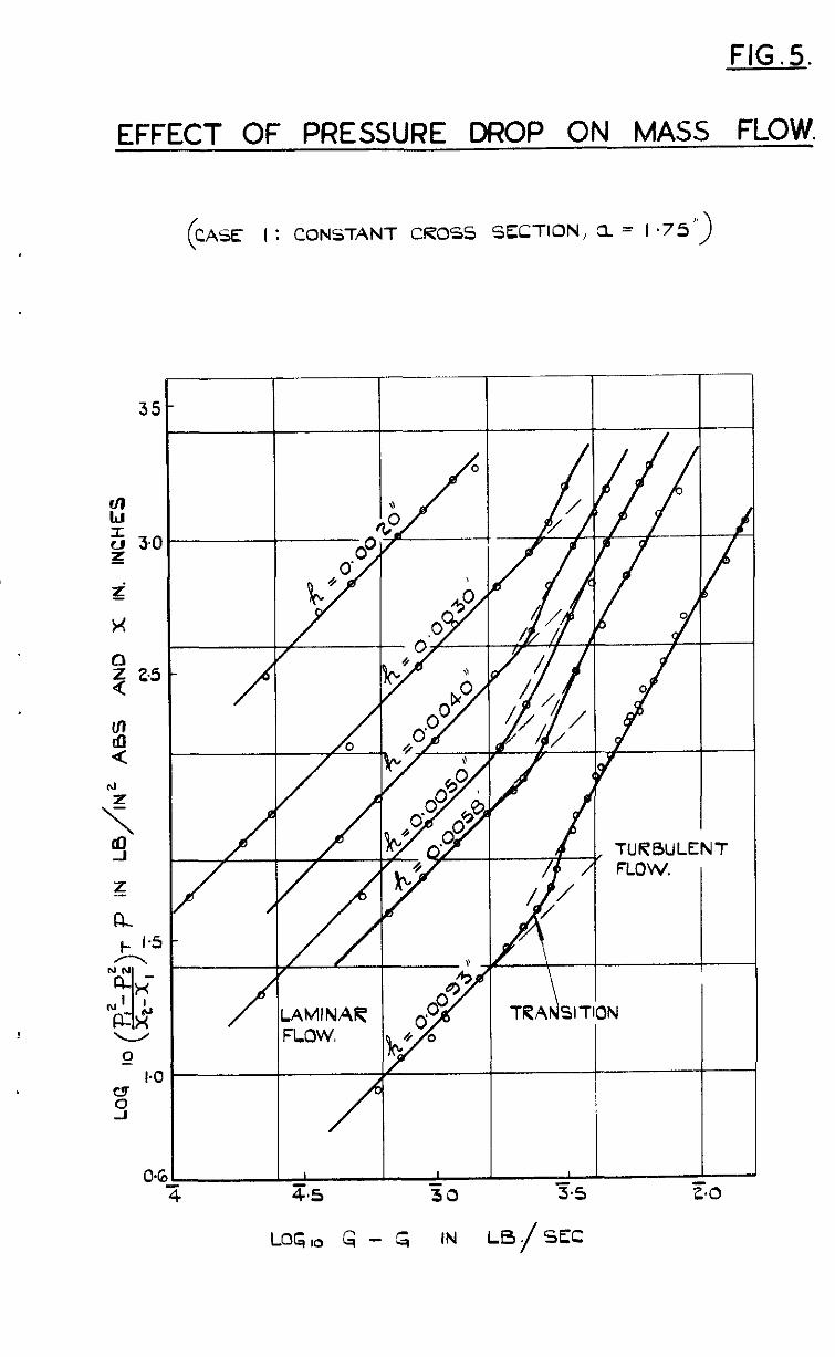
FIG.5.
EFFECT OF PRESSURE DROP ON MASS FLOW.
I : CONSTANT CROSS SECTION, a = 1 .75”)
TRANSIl
- 3.5
-
TURBULENT FLOW.
_.L
IN 3 t.0
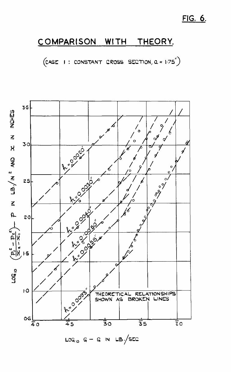
FIG. 6.
A
COMPARISON WITH THEORY.
( CASE I : CONSTANT CROSS SECTION, a = b75”)
3.5 - //
/ / / ,

FIG. 7.
SCALE EFFECT IN CASE I.
0 038
0 034
4 0 030
I
!2 w
OGO8
0 5,QOO lO,QQQ
RCfNOLDS NUMBER - Re

FlG.8. PRESSURE DISTRIBUTION IN THE SLOT:
(CASE 2 : CONSTANT DEPTH , 4 = 3.6” x iOr3a = o< SW)
60
0 t j
I \ 0 I” 2” 3” 4 43’l
DISTANCE FROM RESERVOIR - INCHES
WIDTH INCREASINL; - o( = 0-I
0 I ,a 2” 3” 4 49”
DISTANCE FROM RfSfRVOlR - INCHES
WIDTH INCREASINq - M=OZ
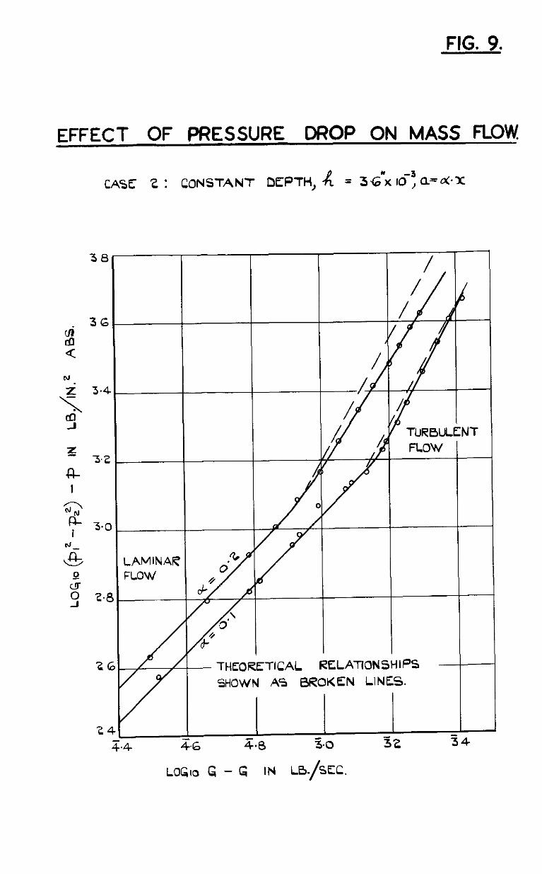
FIG. 9.
EFFECT OF PRESSURE DROP ON MASS FLOW.
CASE 2 : CONSTANT DEPTH, 4 = 34.5 IO-; Q=d*Y
38
LAMINAF FLOW
I I / I
- THEO:OREITICAL RELATIONSHIPS SHOWN AS BROKEN LINES.
6 z.8 3.0 52 34
LOG10 G - G IN LB./SEC.
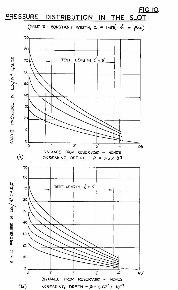
FIG IO. PRESSURE DISTRIBUTION IN THE SLOT.
( CASE: 3 : CONSTANT WIDTH, a = I a3; --IL = /3.x)
30 I I I I
I I
(9
DISTANCE FROM RESERVOIR - INCHES INCR’EWNG, DEPTH - p = 0.5 x la 3
90 I
80 I I 70 R ” TEST LENCTH y= 3*
60
50
40
30
20
IO
0 0 I 2. 3” 4 4-9”
DISTANCE FROM RESERVOIR - INCHES
w INCRE,‘WN~ DEPTH - p = 0*67*X lO-3

FIG. II.
EFFECT OF PRESSURE DROP ON MASS FLOW.
(CASE 3: CONSTANT WIDTH, a = 1.83’: di = p .x)
38
36
THEORETICAL RELATIONSHIPS SHOWN AS BROKfN LINES
T.6 5.0 32 34 56
LOG10 4 - G IN LB/SEC

FIG. 12.
SCALE EFFECT IN CASE 3.
(CORRECTED VALUES 0~ R’>
0 08
0 07
006
0 05
0 04
0.03
o-0;
0 01
0
t
RESULTS
(A= /WC) Q p = 049 x 10-3
A p = 0.64 x ro-3
/
,A= 3
Rf?
r!?i A=
r
r SI
IO 1000 2000 3000
REYNOLDS NUMBER - Re
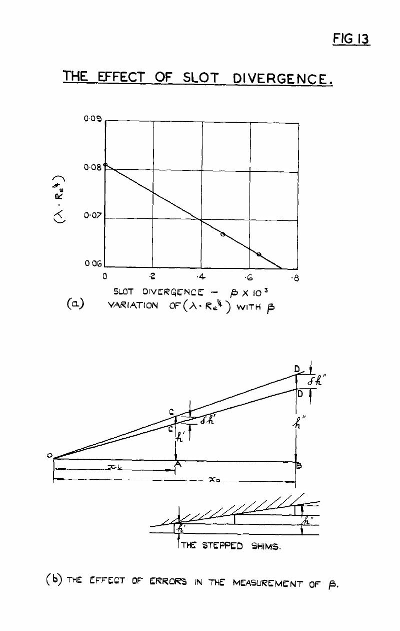
FIG 13
THE EFFECT OF SLOT DIVERGENCE.
0
(4
SLOT DlVER~fNCE - ,f3 X IO3
VARIATION Of (h. Reg) WITH /3
0 B
THE: STEPPED SHIMS.
(b) THE fFFfCT OF ERRORS IN THf MEASLlRfMf NT OF /3.
f IG 14.
MACH NUMBER VARIATION.
0 a DISTANCE FROM RESERVOIR - INCk VARIATION ALONG THE SLOT, h = 5.80 x IO+ IN.
1 , I I I
+ I X
043 - /I I
1 % 0.4 O-6 MASS &V PARAMETER, $A-
03 I LB/SEC. IN!
D
(9 EXIT MACH NUMBER DS 47612llIR.72 Kj 8150 DL

C.P. No.13 (12329)
ARC. Technical Report
S.Q. Code No 23.90%.13