the use of plane-parallel ionization chambers in · iaea trs-381 the use of plane-parallel...
TRANSCRIPT
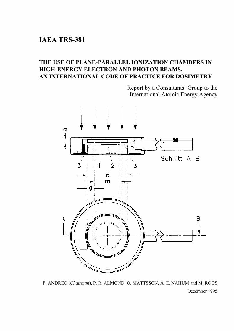
IAEA TRS-381
THE USE OF PLANE-PARALLEL IONIZATION CHAMBERS IN HIGH-ENERGY ELECTRON AND PHOTON BEAMS. AN INTERNATIONAL CODE OF PRACTICE FOR DOSIMETRY
Report by a Consultants’ Group to the International Atomic Energy Agency
P. ANDREO (Chairman), P. R. ALMOND, O. MATTSSON, A. E. NAHUM and M. ROOS
December 1995

ii
Report Committee
PEDRO ANDREO, Chairman§ Head Dosimetry Section RIHU International Atomic Energy Agency P. O. Box 100 A-1400 VIENNA Austria
PETER R. ALMOND Department of Radiation Oncology James Graham Brown Cancer Center University of Louisville Louisville, Kentucky 40202 U. S. A.
OLOF MATTSSON MFT-Therapeutic Radiation Physics Sahlgrenska University Hospital S-413 45 Gothenburg Sweden
ALAN E. NAHUM Joint Department of Physics The Institute of Cancer Research and The Royal Marsden NHS Trust Sutton, Surrey SM2 5PT United Kingdom
MARTIN ROOS Gruppe für Photonen- und Elektronendosimetrie Physikalisch-Technische Bundesanstalt Laboratorium 6.43 Bundesallee 100 D-38023 Braunschweig Germany
§ Formerly at Department of Medical Radiation Physics Karolinska Institute - University of Stockholm S-171 76 Stockholm Sweden

IAEA Code of Practice for plane-parallel ionization chambers
FOREWORD
In 1987 the IAEA published a report entitled "Absorbed Dose Determination in
Photon and Electron Beams. An International Code of Practice" (IAEA Technical Reports
Series No. 277), to advise users how to obtain the absorbed dose in water from measurements
made with an ionization chamber, calibrated in terms of air kerma. For high-energy photons
(energies above 1 MeV) the chamber calibration was at a single photon quality (Cobalt-60
gamma-rays). The Code of Practice described procedures and provided data to use such
ionization chambers to obtain absorbed dose for higher energy photons and also for electron
beams. It was so designed that a variety of cylindrical chambers could be used, which
represented the existing conditions worldwide. However, most national and international
dosimetry protocols recognized the advantages of plane-parallel ionization chambers,
explicitly for electron beams and especially low-energy electron beams (below 10 MeV).
Although this was acknowledged in TRS-277, the calibration and use of these chambers were
not fully developed.
iii
pp
Since the publication of TRS-277 in 1987, various recommendations for the specific
procedures for the use of plane-parallel ionization chambers have been published. Additional
knowledge about the use of cylindrical chambers has also appeared. Accordingly the IAEA
formed an international working group, which met in 1992, to review the status of IAEA
TRS-277. The working group, which consisted of P. Andreo, K. Hohlfeld and A. Nahum,
proposed the formation of a consultants’ group, to prepare a document in the Technical
Reports Series on the use of plane-parallel ionization chambers in high-energy electron and
photon beam dosimetry. This group (P. Almond, U.S.A., P. Andreo, Spain, O. Mattsson,
Sweden, A. Nahum, United Kingdom and M. Roos, Germany) met during 1994 and 1995 to
write the report, which has resulted in the present publication. This both complements and
extends IAEA TRS-277. It describes options on how to calibrate plane-parallel chambers,
against air-kerma or absorbed dose to water standards at Cobalt 60 gamma ray energies, in
order to obtain ND,air the absorbed-dose-to-air chamber factor or the chamber
absorbed dose calibration factor respectively. The use of these chambers to calibrate therapy
electron beams, as well as relative dose measurements for photon and electron beams, is
presented. It also updates some of the data and concepts in TRS 277.
ND,w,Copp

iv
It is believed that this report will fill in the gaps that existed in IAEA TRS-277 with
respect to plane-parallel chambers and will result in improved accuracy in radiotherapy when
these chambers are used.
The working group was convened during the period when H. Svensson was Head of
the Dosimetry Section, and continued under K. Zsdansky as Acting Head. It completed its
task after P. Andreo became Head of Dosimetry.
ACKNOWLEDGEMENTS
The authors wish to acknowledge valuable suggestions and criticism from
M. Boutillon, A. Bridier, A. Brosed, K.-A. Johansson, M.C. Lizuain, B. Nilsson, H. Nyström,
Å. Palm, D.W.O. Rojers, C. Ross, J. Seuntjens and the students of Radiation Physics at Umeå
University.

IAEA Code of Practice for plane-parallel ionization chambers
v
CONTENTS page
Foreword..........................................................................................................................iii
Acknowledgements.......................................................................................................... iv
1. INTRODUCTION ........................................................................................................ 1
2. UPDATE OF THE INFORMATION IN TRS-277. ..................................................... 3
3. EQUIPMENT ............................................................................................................. 10 3.1. Phantom ............................................................................................................. 10 3.2. Measuring assembly .......................................................................................... 12 3.3. Chamber assembly............................................................................................. 12
3.3.1. Chamber properties for electron radiation............................................. 14 3.3.2. Chamber properties for photon radiation............................................... 16 3.3.3. Characteristics of some plane-parallel chamber types........................... 17
4. BEAM QUALITY SPECIFICATION........................................................................ 21 4.1. Electron beams................................................................................................... 21
4.1.1. Determination of the mean energy at the phantom surface, E- o ............ 21
4.1.2. Ranges measured in plastic phantoms ................................................... 23
4.1.3. Determination of the mean energy at depth in the phantom, E- z........... 25
4.2. Photon beams. .................................................................................................... 26
5. NK-BASED FORMALISM AND DETERMINATION OF ND,air FOR PLANE-PARALLEL IONIZATION CHAMBERS................................................. 27 5.1. Formalism .......................................................................................................... 27 5.2. Determination of ND,air for plane-parallel chambers ........................................ 28 5.3. The Electron-Beam Method............................................................................... 30
5.3.1. Choice of phantom................................................................................. 31 5.3.2. Reference conditions and experimental set-up ...................................... 31 5.3.3. Choice of reference chamber ................................................................. 32
5.4. Alternative calibrations of plane-parallel ion chambers in a 60Co beam .......... 32 5.4.1. Calibration at depth in a phantom.......................................................... 33 5.4.2. Measurement free in air ......................................................................... 35
6. ND,w-BASED FORMALISM AND DETERMINATION OF ND,w FACTORS FOR PLANE-PARALLEL IONIZATION CHAMBERS ........................................ 36 6.1. Formalism .......................................................................................................... 37 6.2. Determination of ND,w for plane-parallel chambers ........................................ 38 6.3. Calibration in a 60Co beam................................................................................ 40
7. USE OF PLANE-PARALLEL CHAMBERS IN ELECTRON BEAMS .................. 41 7.1. Determination of the absorbed dose to water under reference conditions......... 41
7.1.1. Reference conditions.............................................................................. 41 7.1.2. Correction for influence quantities ........................................................ 43 7.1.3. Determination of the absorbed dose to water at the reference depth..... 47

7.1.3.1. Measurements in plastic phantoms. ........................................ 50 7.2. Determination of the absorbed dose to water under non-reference
conditions ......................................................................................................... 51
8. USE OF PLANE-PARALLEL CHAMBERS IN PHOTON BEAMS....................... 53 8.1. Determination of the absorbed dose to water under non-reference
conditions ......................................................................................................... 53
9. THE UNCERTAINTY IN ABSORBED DOSE DETERMINATION AT THE REFERENCE DEPTH USING PLANE-PARALLEL CHAMBERS IN ELECTRON BEAMS ............................................................................................... 55 9.1. Estimation based on ND,air calibration .............................................................. 55
9.1.1. The electron-beam method .................................................................... 56 9.1.2. In-phantom measurements in a 60Co beam ........................................... 56 9.1.3. Measurements free in air in a 60Co beam.............................................. 57
9.2. Estimation based on ND,w calibration .............................................................. 64
10. A CODE OF PRACTICE FOR THE CALIBRATION AND USE OF PLANE-PARALLEL IONIZATION CHAMBERS............................................................... 71 10.1. Corrections for influence quantities ................................................................ 71 10.2. Electron beams................................................................................................. 72
10.2.1. Beam quality specification .................................................................. 72 10.2.2. Determination of the ND,air factor of plane-parallel chambers ........... 75
10.2.2.1. The electron-beam method.................................................... 76 10.2.2.2. Measurements in a 60Co gamma -ray beam.......................... 78
10.2.3. Determination of the ND,w factor of plane-parallel chambers in a 60Co gamma-ray beam ......................................................................... 81
10.2.4. Absorbed dose determination in electron beams: absolute dosimetry under reference conditions................................................... 82
10.2.5. Absorbed dose determination in electron beams: relative dosimetry. ............................................................................................. 84 10.2.5.1. Central axis depth-dose distributions.................................... 85 10.2.5.2. Output factors versus field size............................................. 86
10.3. Photon beams................................................................................................... 86 10.4. Tables............................................................................................................... 87
APPENDIX A. EXAMPLES ....................................................................................... 100 A.1. Determination of the absorbed-dose-to-air chamber factor for the
reference chamber .......................................................................................... 100 ND,air
ref
A.2. Determination of the absorbed-dose-to-air chamber factor for a plane-parallel chamber using electron radiation ............................................ 101
ND,airpp
A.3. Determination of the absorbed dose to water in electron beams using a plane-parallel ionization chamber with factor ................................... 106 ND,air
pp
A.4. Determination of the absorbed dose to water in electron beams using a plane-parallel ionization chamber with factor ................................ 108 ND,w,Co
pp
vi

IAEA Code of Practice for plane-parallel ionization chambers
APPENDIX B. STOPPING-POWER RATIOS IN CLINICAL ELECTRON BEAMS. .................................................................................................................. 111 B.1. Energy-range relationship ............................................................................... 111 B.2. Validity of the sw,air (E o, z) selection procedure............................................ 114 B.3. Recent developments ...................................................................................... 117
APPENDIX C. CHAMBER PERTURBATION FACTORS IN ELECTRON AND PHOTON BEAMS.................................................................................................. 119 C.1. Electron beams ................................................................................................ 119
C.1.1. Cavity and wall effects........................................................................ 119 C.1.2. Experimental work .............................................................................. 121 C.1.3. Conclusions ......................................................................................... 125
C.2. Photon beams .................................................................................................. 125 C.2.1. Cavity and wall effects........................................................................ 125 C.2.2. Build-up region ................................................................................... 129
REFERENCES ............................................................................................................. 131
RELATED IAEA PUBLICATIONS............................................................................ 143
vii

viii

IAEA Code of Practice for plane-parallel ionization chambers
1
1. INTRODUCTION
Most national and international dosimetry recommendations have explicitly
recognised the advantages of using plane-parallel (or parallel-plate) ionization chambers for
the dosimetry of therapeutic beams, especially for low-energy electron beams. Their design
characteristics, mainly regarding the shape and height of the collecting volume, make this
instrument theoretically ideal for ionization measurements in regions with sharp dose
gradients in the beam direction or whenever the uncertainty in the position of the effective
point of measurement of the ionization chamber is to be minimised.
The lack of detailed recommendations in the IAEA Code of Practice, TRS-277 [1],
for the determination of the ND,air absorbed-dose-to-air chamber factor of plane-parallel
ionization chambers has raised discussions on the completeness of the Code of Practice. A
reference to the methods described by NACP [2] was provided which, at the time of writing
TRS-277, were considered well established and well described in the original reference, and
therefore still to be recommended. Research in the field since IAEA TRS-277 was published
has expanded our knowledge on perturbation and other correction factors in ionization
chamber dosimetry, and also constructional details of the chambers have been shown to be
important.
Different countries have published, or are in the processes of publishing, dosimetry
recommendations which include specific procedures for the use of plane-parallel ionization
chambers. An international working group was formed under the auspices of IAEA, first to
review the status and actual validity of IAEA TRS-277 [3] and second to develop an
international Code of Practice for the use of plane-parallel ionization chambers in high-
energy electron and photon beams used in radiotherapy. This document fulfils the second
task; its co-authorship by an international group does not imply a recommendation to
supersede existing national protocols but to complement the IAEA Code of Practice TRS-277
[1] in a field where much development has taken place since its publication. It is noted that
these recommendations do not include the use of plane-parallel ionization chambers for the
dosimetry of low- and medium-energy X-rays.
In relation to other recent recommendations [4-6] one of the main differences of the

P. Andreo, P. Almond, O. Mattsson, A. Nahum, M. Roos
2
present procedures refer to the recommendations regarding either the methods for the
determination of ND,air (ND in TRS-277 or Ngas in [5, 7]) of plane-parallel ionization
chambers or their use in photon beams. The main recommendation to determine ND,air in this
document is an experimental determination in an electron beam, against a reference ionization
chamber having a calibration factor NK and a known chamber factor ND,air. The procedure is
consistent with the recommendations of earlier dosimetry protocols [2, 7, 8], and in some
cases the method was also endorsed for thimble (cylindrical) chambers whenever relevant
information related to their construction was unknown to the user [8]. The traceability of this
procedure to Primary Standards is guaranteed through the calibration of the reference
chamber, as with other field instruments commonly used in radiotherapy dosimetry.
The formalism for the practical use of plane-parallel ionization chambers is
consistent with that given in IAEA TRS-277. In photon beams, as opposed to electrons,
plane-parallel ionization chambers are not recommended here for absolute absorbed dose
determinations (absolute in the sense of dose per meter reading), but for relative
measurements only. Emphasis is given to corrections, which have special importance in
plane-parallel chambers, such as polarity effect and recombination. Whenever available,
updated data on quantities and correction factors are provided. Attention has been given to the
use of the chambers in non-reference conditions and relative dosimetry procedures where
ND,air is not needed; these are not usually included in other recommendations (except TG-25
of AAPM [9]).
The present Code of Practice aims also at updating information and procedures in
IAEA TRS-277 regarding recent developments in radiotherapy ion-chamber dosimetry that
are directly related to or might be of interest for the use of plane-parallel ionization chambers.
At this point it is important to emphasize the major development work in progress at the
Primary Standard Dosimetry Laboratories (PSDLs) to provide calibrations of ionization
chambers in terms of absorbed dose to water [10-12] at a reference quality Qo. At present,
efforts are being addressed to providing ND,w,Qo 1 calibrations for photon beams, mainly 60Co
gamma-rays and to a lesser extent high-energy bremsstrahlung beams and electron beams
1 Because calibration factors in terms of absorbed dose to water can be obtained in different beam qualities whenever a possibility for confusion exists a subscript will be added. In this context an index “Co” refers to 60Co γ-rays, “X” to high-energy photons, and “E” to electron beams, ND,w,Co, ND,w,X, and ND,w,E respectively, so that the first index denotes the calibration quantity, the second is the medium where the quantity is measured, and the third the quality of the beam used for calibration [13]. For simplicity, ND,w without additional subscript refers always to the reference quality 60Co.
IAEA Code of Practice for plane-parallel ionization chambers
[14-18]. A practical approach is to provide users with ND,w at a reference quality, usually 60Co, and apply beam quality correction factors when the calibrated instrument is used with
other beam qualities or modalities used in Radiotherapy [10, 13, 19, 20]. To be consistent
with the developments in the field, this Code of Practice also includes a calibration procedure
for plane-parallel ionization chambers based on ND,w.
The structure of this report differs from TRS-277 in that the practical
recommendations and data have been placed in a single Section. This Section 10 is
effectively the Code of Practice for plane-parallel ionization chambers. The reader can
carry out a chamber calibration or an absolute dose determination without searching for the
various procedures or tables through the whole text. Section 2 is an update of the information
given in TRS-277. Details of all the necessary dosimetric procedures, as well as their
justification, are given in Sections 3 to 9. Examples with detailed procedures are included in
Appendix A. Appendices B and C provide an updated review on stopping-power ratios in
clinical electron beams and chamber perturbation factors in electron and photon beams
respectively.
2. UPDATE OF THE INFORMATION IN TRS-277.
Since the publication of the IAEA Code of Practice TRS-277 [1], investigations in
the field have provided new data on certain quantities and a better understanding of the
validity of some of the correction factors commonly used in ion-chamber dosimetry [3, 21]. A
summary is provided here for quantities of relevance to the different methods used with
plane-parallel ionization chambers. The data provided here replace those given in TRS-277,
although in no instance is the final dose determination significantly changed. Most of the
symbols used in this Code of Practice are identical to those used in TRS-277 and ICRU-35
[22]; consequently, only the new symbols used throughout the present document or those
which involve a change in numerical value, will be given in detail 2.
Cpl Material-dependent scaling factor to convert ranges and depths measured in plastic
3
2 In certain instances, especially when ionisation chambers of different design are simultaneously referred to, or
whenever a possibility for confusion exists, a superscript specifying the type of chamber is used. For example, and denote, respectively, the ND ,air
cyl , ND, airpp ND ,air
x ND ,air absorbed dose to air chamber factor of a cylindrical ionisation chamber, a plane-parallel chamber, or a chamber of an unspecified type.
P. Andreo, P. Almond, O. Mattsson, A. Nahum, M. Roos
phantoms into the corresponding values in water. This is the equivalent of the effective density of AAPM TG-25 [9].
hm Factor to correct for the difference in electron fluence in plastic compared to that in water at an equivalent depth. The values have been updated based on a new analysis of published data [6].
kcel Factor to take into account the non-air equivalence of the central electrode of a cylindrical (thimble) ionization chamber for obtaining ND,air from the calibration factor in terms of air kerma, NK, at the reference quality Qo, usually 60Co gamma-rays. As discussed in TRS-277, various investigations have demonstrated an increase in the response of a cylindrical ionization chamber to 60Co irradiation in air with increasing electrode diameter when the electrode is aluminium. This has been verified both experimentally [23] and using Monte-Carlo simulations [24-26]. In most cases the uncertainty in terms of one standard deviation was of the same order as the correction itself or even larger. Recent Monte-Carlo simulations of the effect of metallic central electrodes by Ma and Nahum [27] have decreased considerably the estimated uncertainty of the correction, yielding kcel equal to 1.006±0.1% (uncertainty type-A) for a NE-2571 chamber with a 1 mm diameter aluminium central electrode; this is the value recommended in this report (see also the paragraph below on ND,air).
ND,air Absorbed-dose-to-air chamber factor. From the quantity determined with this factor,
D- air, the absorbed dose to water in a point, Dw, is derived by the application of the Bragg-Gray principle. Many of the factors described below are corrections for the departure from ideal Bragg-Gray behaviour. This factor was called ND in TRS-277, but the subindex air has been included here to specify without ambiguity that it refers to the absorbed dose to the air of the chamber cavity. This is the Ngas of AAPM TG-21 [7]. In this Code of Practice it is given by
ND,air = NK (1 − g) katt kmkcel (2.1)
which is similar to the formulation given in Refs. [28-30] where the factor kcel also appears explicitly. TRS-277 did not include kcel in the equation for ND and therefore this latter factor did not relate solely to the geometrical characteristics of the chamber, i.e. an indirect measure of the cavity volume; kcel was instead included in the pcel-gbl factor (see below). The numerical value of ND,air for cylindrical chambers with 1 mm diameter aluminium electrodes (NE-2571) is a factor 1.006 greater than ND as given in TRS-277. Although the determination of the ND,air
4

IAEA Code of Practice for plane-parallel ionization chambers
5
chamber factor by the user should strictly not be considered as a calibration 3, the use of a reference chamber with a calibration factor NK supplied by a Standards Laboratory provides traceability to national and international standards. For the sake of simplicity the term calibration will sometimes be retained in the present Code of Practice.
ND,w Absorbed-dose-to-water chamber factor, which yields the absorbed dose to water (per electrometer reading unit) in the absence of the chamber at a point in water where the reference point of the chamber 4 is situated and at a reference beam quality Qo. This symbol was given in TRS-277 but in practice its use was restricted to low-energy X-rays. As already mentioned the most common approach is to provide users with ND,w at a reference quality Qo, usually 60Co, and apply beam quality correction factors for other beam qualities. A formalism based on ND,w calibration factors is given in Section 6. Users should be warned of the possibility of confusion arising from the notation ND used by AAPM TG-21 [7] for the ND,w factor.
pQ Overall perturbation factor of ionization chambers for in-phantom measurements at a
beam quality Q. It is equal to the product of various factors correcting for different
effects, each correcting for small perturbations; in practice these are pcav, pcel, pdis
and pwall.
pcav Factor that corrects for effects related to the air cavity, predominantly the in-scattering of electrons [22, 32] that makes electron fluence inside a cavity different from that in the medium in the absence of the cavity (see Appendix C). It is denoted here by cav to emphasise that it is exclusively concerned with effects due to the air cavity, rather than the wall material. The in-scattering effect was the only perturbation mechanism considered by TRS-277 for electron beam dosimetry, whereas it was assumed to be negligible for photon beams. The present pcav therefore coincides numerically with the overall perturbation factor pu for electron beams in TRS-277. This factor is generally assumed to be equal to unity for plane-parallel chambers in electron beams. It is important to emphasise that the pu or pcav factors for electron beams are strictly valid at the reference depths only, and
3 The criteria for deciding the kind of institution where an ionization chamber should be calibrated are not
uniform. Advantages and disadvantages with calibrations at a Secondary Standard Dosimetry Laboratory (SSDL) or a Hospital have been discussed in the recent IAEA TRS-374 on the Calibration of Dosimeters used in Radiotherapy [31].
4 The point in the chamber specified by a calibration document to be that at which the calibration factor applies [31]. For plane-parallel ionization chambers the center of the inner side of the front wall is recommended in this Code of Practice.
P. Andreo, P. Almond, O. Mattsson, A. Nahum, M. Roos
6
therefore their use at other depths is an approximation. This restriction was already pointed out in Section 7.3.1 of TRS-277, dealing with non-reference determinations of absorbed dose.
pcel Factor that corrects for the effect of the central electrode of a cylindrical ionization chamber during in-phantom measurements in high-energy photon and electron beams. This perturbation was analysed first in the experimental work of Mattsson [33]. The product kcel pcel was called pcel in TRS-277, although it should have been named pcel-gbl to specify without ambiguity that it is a global correction factor, see Refs. [28-30] 5. Problems associated with the correction for the influence of the central electrode during the procedure to determine ND,air for plane-parallel ionization chambers in electron beams have been reported [30]. It was found that the global correction for a Farmer-type chamber of 0.8% in electron beams recommended by TRS-277 and other protocols [4, 34] did not produce a consistent determination of the absorbed dose in electron beams. The Monte-Carlo simulations of Ref. [27] have supported the conclusion that the pcel-gbl factor recommended by TRS-277 is too large; identical corrections have been found for the existing solid and hollow electrodes. Using the results in Ref [27] for 60Co in air (kcel equal to 1.006) and for high-energy electrons in a phantom (pcel equal to 0.998), the global correction in electron beams amounts to 1.004 for a NE-2571 Farmer chamber, which is half of the correction recommended in TRS-277. This result is consistent with the analysis of the experimental results of Mattsson and Johansson [35] given in Ref [30]. The effect increases for low electron energies. Additional experimental determinations comparing Fricke to ionization dosimetry [36] have also arrived at a smaller correction factor than the recommendation by TRS-277, in good agreement with the results reported above. The agreement between these new sets of data confirms the need for a decrease in the recommended correction factor, and the data for pcel in the present report have been adjusted accordingly and separated from kcel.
pdis Factor that accounts for the effect of replacing a volume of water with the detector cavity when the reference point of the detector volume is taken to be at the chamber center. It is the alternative to the use of an effective point of measurement of the chamber, Peff, shifted from the center for the standard calibration geometry, i. e. a
5 The reason to separate both components in this report is not only to achieve a consistent definition of the
ND,air chamber factor; during the calibration procedure in terms of ND,w,Qo only in-phantom measurements are involved and the use of the pcel-gbl factor is inappropiate. The determination of the dose to water with cylindrical chambers using the ND,air-based formalism is not modified by the separation of pcel-gbl (TRS-277) into its components kcel and pcel.

IAEA Code of Practice for plane-parallel ionization chambers
7
radiation beam incident from one direction. When ionization chambers are calibrated in a phantom using 60Co or high-energy photon beams it is sometimes cumbersome to position the chambers so that their effective points of measurement are at the same depth. The centres of the ionization chambers would have to be at different depths depending on the beam quality and the diameters of the chambers. This would increase the likelihood of errors being made in the setting up and is a reason for referring absorbed dose to water calibration factors to the chamber center. Experimental data from Johansson et al [37] consistent with the position of Peff discussed below are recommended in this report. The factor pdis is related to the Prepl of AAPM TG-21 [7] whose data are based on first scatter calculations by Cunningham and Sontag [38] see Refs. [19, 20, 39]. As described by Andreo [19, 40] (see also Refs. [21, 41]) the AAPM TG-21 set yield differences of about 0.5% for a Farmer-type chamber compared with the experimental results recommended here [37].
Peff The effective point of measurement of the ionization chamber. For cylindrical chambers in electron beams, TRS-277 and other dosimetry protocols recommend a shift of Peff from the centre of the chamber of 0.5 r, where r is the inner radius of the chamber, towards the source. In megavoltage photon beams the experimental and theoretical results on the effective point of measurement of an ion-chamber have been reviewed [3, 21]. With the exception of very high-energy photon beams (mainly obtained with old betatrons where shifts of about 0.8 r were measured) most results yield an average value of the shift close to 0.6 r at depths used for beam calibration for therapeutic photon beams including 60Co gamma-rays [37]. Note that TRS-277 recommended a shift of 0.5 r for the latter case and 0.75 r for high-energy photon beams. It should be noted that, due to the gradient of dose in the volume occupied by the chamber, the two shifts quoted in the literature for 60Co and photons around 6-8 ”MV”, namely about 0.50 r and 0.75 r, correspond to depths with differences in percentage dose close to 0.5 % for a Farmer-type chamber. In the present document a shift equal to 0.6 r is recommended for all photon beams with qualities equal to or higher than 60Co γ-rays. For practical purposes a value of 0.55 r for both photon and electron beams is acceptable. For plane-parallel ionization chambers Peff is usually assumed to be situated in the center of the front surface of the air cavity. This assumption might fail if the chamber design, regarding the ratio of cavity diameter to cavity height as well as cavity height to guard-ring width, does not follow certain requirements (see Section 3).
pwall Factor that corrects for the non-medium equivalence of the chamber wall material (see Appendix C). For cylindrical chambers in photon beams this factor is

P. Andreo, P. Almond, O. Mattsson, A. Nahum, M. Roos
8
determined analytically in most dosimetry protocols using the 2-component model given by Almond and Svensson [42] (Eq. (25) in TRS-277) or the extension by Gillin et al [43] and Hanson and Dominguez-Tinoco [44] to three components to take into account the thin waterproofing plastic or rubber sleeve normally used to protect the chamber in a water phantom. However, discrepancies between experiments and the 2- or 3-component analytical model have been reported by Ross and Shortt [45]. The present pwall coincides with the generic perturbation factor pu for photon beams in TRS-277 6. It has been demonstrated, both experimentally [33, 36, 47] and by Monte-Carlo simulations [48], that the analytical expression cannot be used for plane-parallel ionization chambers due to their generally inhomogeneous design. Although pwall factors at 60Co have now been determined for most plane-parallel ionization chambers [49], the validity of universal factors for a chamber from a particular manufacturer has been questioned due to significant chamber-to-chamber variations for the same model [30, 50]. Furthermore, departures from manufacturer specifications have been found in commercially available chambers [51]. In electron beams wall effects have implicitly been assumed to be negligible to date [1, 52, 53]. There is, however, experimental evidence that this may not be so for certain combinations of plane-parallel chamber and phantom material due to backscattering differences [54] (see Appendix C). More work is required before any non-unity values for pwall can be recommended. Experimentally it is the overall perturbation factor pQ for plane-parallel ionization chambers that has been determined in electron beams (equal to the product pcav pwall) and non-unity values are given for certain chambers at low energies (Section 10).
ps Factor to correct for the lack of saturation of charge collection (due to ion recombination) in an ionization chamber. The determination of the recombination correction factor for plane-parallel ionization chambers using the two-voltage method, as in TRS-277, has been shown to have limitations for most chambers due to the lack of linearity of saturation curves in the region of interest [55]. In order to decrease the influence of ps in the dosimetry procedure it is recommended here to use the same voltage-ratio for the determination of ps in the calibration beam and in the user’s beam. An alternative procedure to derive ps based on Boag’s theory [56] is also provided in this report.
Q General symbol to indicate the quality of a radiation beam, either photons or
6 The TPR scale in Fig. 16 in TRS-277 for α in high-energy photon beams should be shifted such that 0.60 is at
the origin [46].

IAEA Code of Practice for plane-parallel ionization chambers
electrons. Qo indicates the reference quality used for calibration.
Rcsda Linear continuous-slowing down range (csda), equal to ro/ρ.
sw,air Spencer-Attix (∆ = 10 keV) stopping-power ratio, water to air. New calculations of
sw,air for electron beams have been performed by Andreo [57] based on the two sets
of density-effect corrections in water given in the ICRU 37 electron stopping power
tables [58]. They are density-effect corrections according to the Sternheimer’s model
and the calculations of Ashley based on semi-empirical dielectric-response functions
(DRF). It was argued that for electron energies used in radiotherapy, where the
density effect in air is negligible, δDRF-based water/air stopping-power ratios
provide a more accurate set of data. Differences in stopping-power ratios due to the
different evaluations of the density effect correction are within 1% at all energies
and depths of interest. There is inadequate information, however, on the density
correction used in the set of values actually in use in TRS-277 and most national
dosimetry protocols. A new set of data is provided here based on Ashley density-
effect corrections for water. Compared with the stopping-power ratios in TRS-277,
differences are small for the most commonly used electron energies in radiotherapy,
being close to 0.5 % at most depths (see Fig. 7.4). The adoption of the new values is
justified in terms of the lack of ambiguity in the corrections used and higher
accuracy of the present set of data. As in TRS-277 stopping-power ratios at the
reference depth are selected according to the so-called sw,air (E o, zref ) rule, where E-
o is the mean energy of the electron beam at the phantom surface (see Appendix B) .
A procedure for selecting stopping power ratios for relative measurements if the
energy and angular spread of the electron beam are not negligible was given in TRS-
277 7. This method is not recommended in the present Code of Practice as it does not
overcome the limitations of the sw,air (E o, z) method described in Appendix B.
zav Average depth (in cm) of electron penetration; zav/Rcsda is known as the detour
factor (see for example ICRU 49 [59] where this concept is discussed for protons
and alpha particles). The concept of detour factor was implemented in the context of
electron dosimetry by Harder [60] establishing empirical laws of electron absorption.
It should be noted that the ICRU 49 [59] and Harder's [60] definitions of detour factors 7 The procedure was based on E o and a scaled depth z´= z Rp
calc/Rpmeas, Rp
calc being the practical range of monoenergetic electrons of energy E o and Rp
meas the experimental Rp in water for the actual conditions.
9

P. Andreo, P. Almond, O. Mattsson, A. Nahum, M. Roos
are reversed, the former giving values less than unity, denoting a shortening of the
particle depth of penetration compared with pathlength. Harder empirical laws were
mainly based on electron transmission coefficients [61] of 4-30 MeV electrons in C,
Al, Cu, Cd and Pb. Recent investigations using the Monte-Carlo method [62] have
lead to an empirical equation of detour factors as a function of the mean atomic
number, for plastic materials of interest in electron beam dosimetry. Between 1 and
50 MeV, electron detour factors in plastic materials can accurately be obtained from
zav
Rcsda= 1 +
a1Z a2 (1+ a3τ )1 + a4τ
−1
(2.1)
where a1=0.2190, a2=0.7719, a3=0.00833 and a4=0.10842. τ is the electron kinetic
energy in units of the electron rest energy (mc2 = 0.511 MeV) and the mean atomic
number is defined by ICRU 35 [22] as
Z =wj
Z j2
Ajj∑
wj
Zj
Ajj∑
(2.2)
where wj is the fraction by weight and Zj and Aj pertain to the j’th constituent of the
plastic.
zref Depth of reference (in cm) for in-phantom measurements at a beam quality Q.
3. EQUIPMENT
3.1. PHANTOM
Water is recommended in the IAEA Code of Practice, TRS-277 [1] as the reference
medium for absorbed dose measurements both for photon and electron beams and the same
criterium is followed in this report. Solid phantoms in slab form such as polystyrene,
10

IAEA Code of Practice for plane-parallel ionization chambers
11
PMMA8, and certain water-equivalent plastics (see ICRU 44 [63] and Ref. [64]) may be used
for low-energy (below 10 MeV approximately) electron beam dosimetry. Nevertheless, the
dose determination must always be referred to water.
Ideally, the phantom material should be water equivalent for electron beams. This
means that the linear collision stopping power, the linear radiative stopping power and the
linear scattering power should have the same values as for water for the whole electron
energy range under consideration (see ICRU 35 [22]). Since these conditions are only
fulfilled to a certain degree by common phantom materials, it is necessary to convert data
determined in plastic materials into those for water. In plastic materials, as a consequence of
their high carbon content, their effective atomic number is usually lower than that of water,
resulting in too low a linear scattering power when the linear collision stopping power is
equal to that of water. In the case of high-impact polystyrene and some types of water-
equivalent plastics this difference is reduced by the addition of a high-Z material to the
plastic.
For all materials the phantom should extend to at least 5 cm beyond all four sides of
the largest field size employed at the depth of measurement. There should also be a margin of
approximately 5 cm beyond the maximum depth of measurement.
When phantoms of insulating materials are adopted, users must be aware of the
problems resulting from charge storage, predominantly in the case of measurements with
thimble chambers in electron beams [65-68]. This mechanism might play an important role
during the calibration procedure for plane-parallel chambers in electron beams. The effect
may cause a very high electric field strength around the chamber, directly influencing the
electron fluence distribution and therefore affecting the reading of the chamber. In order to
minimise this effect the thickness of the sheets constituting the phantom should be as small as
possible, in no case exceeding 2 cm [1, 67]. The actual thickness of the particular slabs, and
the variation of the thickness over the slab area, should be measured since deviations from the
data stated by the manufacturers are frequently observed, particularly in the case of thin slabs.
The density of each sample should also be determined. Furthermore, care must be taken to
ensure that air layers between the slabs are avoided.
The influence of the charge storage on the electron fluence distribution appears to be
8 Polymethyl Methacrylate, also known as acrylic. Trade names are Lucite, Plexiglas or Perspex.
P. Andreo, P. Almond, O. Mattsson, A. Nahum, M. Roos
12
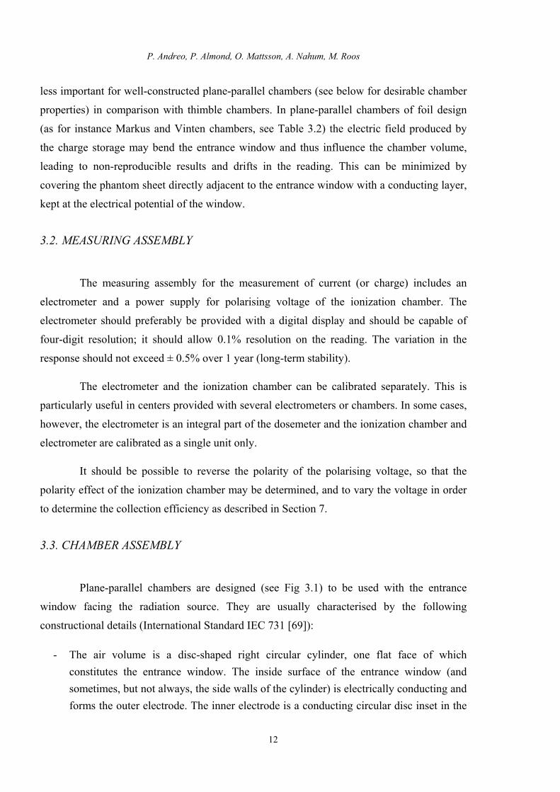
less important for well-constructed plane-parallel chambers (see below for desirable chamber
properties) in comparison with thimble chambers. In plane-parallel chambers of foil design
(as for instance Markus and Vinten chambers, see Table 3.2) the electric field produced by
the charge storage may bend the entrance window and thus influence the chamber volume,
leading to non-reproducible results and drifts in the reading. This can be minimized by
covering the phantom sheet directly adjacent to the entrance window with a conducting layer,
kept at the electrical potential of the window.
3.2. MEASURING ASSEMBLY
The measuring assembly for the measurement of current (or charge) includes an
electrometer and a power supply for polarising voltage of the ionization chamber. The
electrometer should preferably be provided with a digital display and should be capable of
four-digit resolution; it should allow 0.1% resolution on the reading. The variation in the
response should not exceed ± 0.5% over 1 year (long-term stability).
The electrometer and the ionization chamber can be calibrated separately. This is
particularly useful in centers provided with several electrometers or chambers. In some cases,
however, the electrometer is an integral part of the dosemeter and the ionization chamber and
electrometer are calibrated as a single unit only.
It should be possible to reverse the polarity of the polarising voltage, so that the
polarity effect of the ionization chamber may be determined, and to vary the voltage in order
to determine the collection efficiency as described in Section 7.
3.3. CHAMBER ASSEMBLY
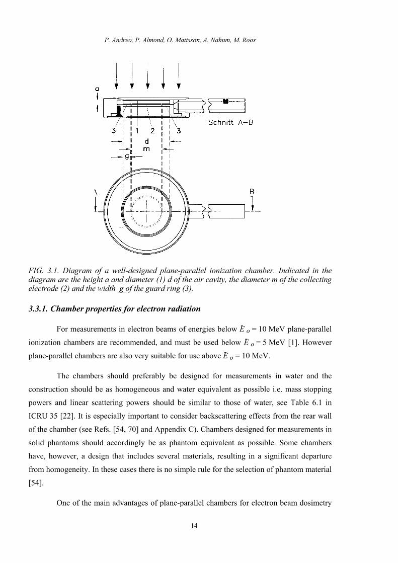
Plane-parallel chambers are designed (see Fig 3.1) to be used with the entrance
window facing the radiation source. They are usually characterised by the following
constructional details (International Standard IEC 731 [69]):
- The air volume is a disc-shaped right circular cylinder, one flat face of which constitutes the entrance window. The inside surface of the entrance window (and sometimes, but not always, the side walls of the cylinder) is electrically conducting and forms the outer electrode. The inner electrode is a conducting circular disc inset in the

IAEA Code of Practice for plane-parallel ionization chambers
13
body insulator which forms the other flat face of the cylinder opposite to the entrance window. The sensitive volume is that fraction of the total air volume through which the lines of electrical force between the inner and outer electrodes pass;
- The inner and outer electrodes are mounted in a supporting block of material (the chamber body) to which the connecting cable is attached. The cable usually exits the body in a direction parallel to the entrance window;
- The sensitive volume is typically between 0.05 cm3 and 0.5 cm3; - The polarising potential is applied to the outer electrode and the signal charge is
collected from the inner electrode; - There is usually a third electrode9 surface between the other two which is not
connected electrically to either of them, but which is designed to be held at the same potential as the inner electrode. If the chamber assembly is fully guarded this third electrode will be present in the air volume as a ring around the inner electrode.
- Plane-parallel chambers for electron radiation 10 have the following typical dimensions: the entrance window thickness is 1 mm or less; the distance between the inner and outer electrodes is 2 mm or less; the diameter of the inner (collecting) electrode is 20 mm or less.
9 Usually called guard ring. 10 These dimensions apply equally well for 60Co gamma-ray and high-energy photon beams.
P. Andreo, P. Almond, O. Mattsson, A. Nahum, M. Roos
FIG. 3.1. Diagram of a well-designed plane-parallel ionization chamber. Indicated in the diagram are the height a and diameter (1) d of the air cavity, the diameter m of the collecting electrode (2) and the width g of the guard ring (3).
3.3.1. Chamber properties for electron radiation
For measurements in electron beams of energies below E- o = 10 MeV plane-parallel
ionization chambers are recommended, and must be used below E- o = 5 MeV [1]. However
plane-parallel chambers are also very suitable for use above E- o = 10 MeV.
The chambers should preferably be designed for measurements in water and the
construction should be as homogeneous and water equivalent as possible i.e. mass stopping
powers and linear scattering powers should be similar to those of water, see Table 6.1 in
ICRU 35 [22]. It is especially important to consider backscattering effects from the rear wall
of the chamber (see Refs. [54, 70] and Appendix C). Chambers designed for measurements in
solid phantoms should accordingly be as phantom equivalent as possible. Some chambers
have, however, a design that includes several materials, resulting in a significant departure
from homogeneity. In these cases there is no simple rule for the selection of phantom material
[54].
One of the main advantages of plane-parallel chambers for electron beam dosimetry
14
IAEA Code of Practice for plane-parallel ionization chambers
15
is the possibility of minimising in-scattering perturbation effects, pcav [32]. Plane-parallel
ionization chambers may be designed so that the chamber samples the electron fluence
incident through the front window, the contribution of electrons entering through the side
walls being negligible. This design justifies considering the effective point of measurement
Peff to be at the centre of the front surface of the air cavity (for such chambers it is assumed
that the position of Peff does not vary with energy). For practical purposes it is also
convenient to choose the reference point of the chamber at the same position. In order to fulfil
the requirements concerning pcav and Peff within a reasonable approximation, plane-parallel
chambers must have a flat cavity, i.e. the ratio of cavity diameter and cavity depth must be
large (of the order of 10), the cavity height should not exceed 2 mm, and the collecting
electrode should be surrounded by a guard electrode having a width not smaller than 1.5 times
the cavity height. Such dimensions are reported to sufficiently reduce the in-scattering
perturbation effect [51, 52, 71]. Furthermore, the diameter of the collecting electrode should
not exceed 20 mm in order to reduce the influence of radial non-uniformities of the beam
profile. In addition the thickness of the front window should be restricted to 1 mm at most to
make measurements at shallow depths possible. It is also necessary for the air cavity to be
vented so that it will equilibrate rapidly with the external pressure and temperature.
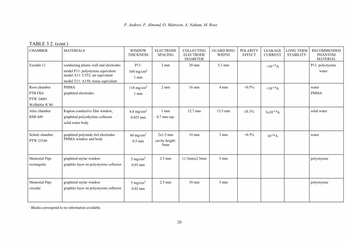
The polarity effect 11 represents a considerable source of uncertainty in dosimetry
with plane-parallel ionization chambers. The magnitude of the effect and its dependence on
the irradiation conditions are often incorrectly assessed. Since for plane-parallel ionization
chambers it is essentially a charge-balance effect, it depends on the energy and the angular
distribution of the incident radiation, the measuring depth in the phantom and also on the field
size. The polarity effect may even change its sign as a function of depth in the phantom. This
can be understood by examining the charge deposition patterns shown in Fig. 3.2. Electrons
deposit a net charge due to the lack of balance between the in- and out-transport of electrons
at various depths. The positive net charge at shallow depths is caused by depletion due to the
forward transport of delta-rays; the highest negative net charge occurs in the vicinity of the
R50 where most of the primary electrons are stopped. Depending on the polarity of the
11 The polarity effect is defined here as half the difference in the absolute values of the readings with positive
and negative polarity divided by the mean value [2], i.e.
0.5 �M
M =
|M+| - |M-||M+| + |M-|

P. Andreo, P. Almond, O. Mattsson, A. Nahum, M. Roos
16
polarising voltage of the chamber and the depth of measurement, the charge deposition in the
collecting electrode may be increased or decreased.
An overview of desirable plane-parallel chamber properties is compiled in Table 3.1.
3.3.2. Chamber properties for photon radiation
Plane-parallel chambers are here recommended for relative measurements of depth-
ionization distributions in photon beams. The desirable chamber properties for this purpose
are essentially the same as those for electron radiation. The restrictions on chamber
dimensions given in Table 3.1 are essential in order to ensure that taking the effective point of
measurement to be at the centre of the front surface of the air cavity is a reasonable
approximation, independent of beam quality and measuring depth (an essential advantage in
comparison with thimble chambers). This is especially important for measurements under non
equilibrium conditions at shallow depths in the build- up region, where even larger ratios of
guard ring width to cavity height could be advantageous.
TABLE 3.1. DESIRABLE PROPERTIES FOR A PLANE-PARALLEL CHAMBER IN ELECTRON RADIATION
Chamber dimensions Front window thickness ≤ 1 mm Collecting electrode diameter ≤ 20 mm Ratio of guard width to cavity height ≥ 1.5 Cavity height ≤ 2 mm
In-scattering perturbation effect, pcav < 1% Backscattering perturbation effect, pwall < 1% Polarity effect < 1% Leakage current < 10-14 A Long-term stability ±0.5%a
a Of response per year for any radiation quality in the rated range

IAEA Code of Practice for plane-parallel ionization chambers
-2
-1
0
1
2
3
0 0.5 1 1.5
50 MeV40 MeV30 MeV
20 MeV10 MeV 5 MeV
scal
ed c
harg
e de
posi
tion
(cha
rge/
elec
t x r o)
scaled depth in water (z/r o)
FIG. 3. 2. Net charge deposition resulting from the absorption of monoenergetic electron beams in water as a function of the scaled depth z/ro (ro is the continuous slowing down approximation range) for various electron energies. The charge per incident electron is normalised according to the reciprocal of the csda ranges for every energy [72].
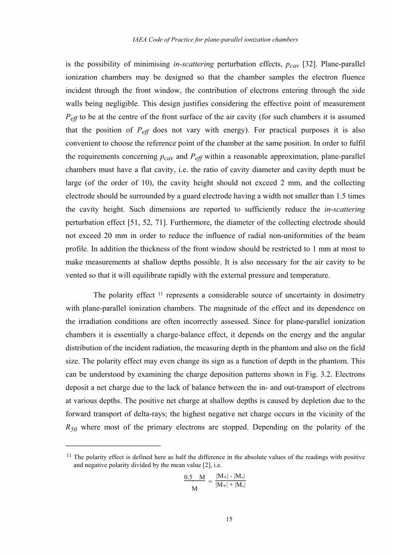
3.3.3. Characteristics of some plane-parallel chamber types
Table 3.2 contains some of the most important design characteristics of commonly
used plane-parallel chambers. In most cases chambers are optimised for electron beam
dosimetry but they are sometimes also recommended for measurements in photon beams.
Special models not included in this table are two chamber types exclusively designed and
recommended for soft X rays (PTW 23342, PTW 23344) which are sometimes also used for
high-energy photon and electron dosimetry. This use is not recommended since the polarity
effect is usually too large for such radiation beams.
Table 3.2 includes materials, dimensions and some performance characteristics. The
data have been stated by the manufacturers (with a few exceptions - Capintec PS-033, Holt
chamber and Attix chamber - the manufacturers performance data do not explicitly include
measurements in photon beams). Ideally, information on the composition and thickness of the
back wall (see Appendix C) should have been included in the Table, but this was not
generally available. If deviations from the specifications have been reported in the literature,
this is noted separately. This applies in many cases to the magnitude of the polarity effect
where differences from chamber to chamber of the same type may have to be taken into
17

P. Andreo, P. Almond, O. Mattsson, A. Nahum, M. Roos
18
account. Also, in the case of chamber types without a remark in Table 3.2, single chambers
may exhibit a considerable polarity effect. Furthermore, during the lifetime of a chamber its
polarity effect may increase. Therefore it is important to check the polarity effect regularly.
Information on perturbation effects is usually not provided by the manufacturer.
The chambers can be generally divided into separate body chambers, constituting the
majority, and phantom-integrated chambers, indicated in the final column. Some of the
chambers are waterproof; water is then stated as one of the recommended phantom materials.
Other differences concern, for example, the variety of approaches used to decrease
the polarity effect. Some designs solely involve thin graphitation of electrodes, others employ
a combination of one or two foil electrodes and a multi-layer design for the collecting
electrode/ isolator system and yet other chambers incorporate three foils to minimise the
amount of material which is mainly responsible for the polarity effect. Therefore the air
volume is divided into up to four ventilated partitions. The ratio of the guard ring width to the
height of the air chamber volume, crucial to the magnitude of the in-scattering perturbation
effect, extends from values close to zero (causing a large perturbation effect) up to a factor of
about 14.

IAEA Code of Practice for plane-parallel ionization chambers
Table 3.2. CHARACTERISTICS OF PLANE-PARALLEL CHAMBER TYPES (as stated by manufacturers) CHAMBER MATERIALS WINDOW
THICKNESS ELECTRODE
SPACING COLLECTING ELECTRODE DIAMETER
GUARD RING WIDTH
POLARITY EFFECT1
LEAKAGE CURRENT1
LONG-TERM STABILITY1
RECOMMENDED PHANTOM MATERIAL
Vinten 631 (Pitman 631)
aluminized mylar foil window graphited mylar foil electrode styrene co-polymer rear wall PMMA body
1 mg/cm2
0.006 mm
2x1 mm cavity height
2mm
20 mm 3 mm <0.2% larger reported
[73]
PMMA(phantom integr.)
NACP01 (Scanditronix). Calcam-1 (Dosetek)
graphite window, graphited rexolite electrode graphite body (back wall) rexolite housing
90 mg/cm2
0.5 mm
2 mm 10 mm 3 mm <0.5% larger reported
[73]
<10-14A ±0.5% polystyrenegraphite water (with water-proof housing)
NACP02 (Scanditronix). Calcam-2 (Dosetek)
mylar foil and graphite window graphited rexolite electrode graphite body (back wall) rexolite housing
104 mg/cm2
0.6 mm
2 mm 10 mm 3 mm <0.5% larger reported
[74]
<10-14A ±0.5% water,PMMA
Markus chamber PTW 23343 NA 30-329 NE 2534
graphite polyethylene foil window graphited polystyrene collector PMMA body, PMMA cap
102 mg/cm2
0.9 mm
(incl. cap)
2 mm 5.3 mm 0.2 mm <0.5% larger reported
[75]
2x10-16A larger
reported
water,PMMA
Holt chamber (Memorial) NA 30-404
graphited polystyrene wall and electrode, polystyrene body
416 mg/cm2
4 mm
2 mm 25 mm 5 mm <1% larger reported
[76]
10-15A ±0.5%
polystyrene (phantom integr.)
PS-033 (Capintec)
aluminized mylar foil window carbon-impregnated air-equivalent plastic electrode, polystyrene body
0.5 mg/cm2
0.004 mm
2.4 mm 16.2 mm 2.5 mm <10-14A ±1% polystyrene
19
P. Andreo, P. Almond, O. Mattsson, A. Nahum, M. Roos
TABLE 3.2. (cont.) CHAMBER MATERIALS WINDOW
THICKNESS ELECTRODE
SPACING COLLECTING ELECTRODE DIAMETER
GUARD RING WIDTH
POLARITY EFFECT
LEAKAGE CURRENT
LONG TERM STABILITY
RECOMMENDED PHANTOM MATERIAL
Exradin 11 conducting plastic wall and electrodes model P11: polystyrene equivalent model A11: C552, air equivalent model T11: A150, tissue equivalent
P11:
104 mg/cm2
1 mm
2 mm 20 mm 5.1 mm <10-15A P11: polystyrene water
Roos chamber PTB FK6 PTW 34001 Wellhöfer IC40
PMMA graphited electrodes
118 mg/cm2
1 mm
2 mm 16 mm 4 mm <0.5% <10-14A waterPMMA
Attix chamber RMI 449
Kapton conductive film window, graphited polyethylene collector solid water body
4.8 mg/cm2
0.025 mm
1 mm 0.7 mm rep.
12.7 mm 13.5 mm ≤0.3% 3x10-14A solid water
Schulz chamber PTW 23346
graphited polymide foil electrodes PMMA window and body
60 mg/cm2
0.5 mm
2x1.5 mm cavity height:
5mm
19 mm 3 mm <0.5% 10-14A water
Memorial Pipe rectangular
graphited mylar window graphite layer on polystyrene collector
5 mg/cm2
0.03 mm
2.5 mm 11.3mmx2.5mm 5 mm polystyrene
Memorial Pipe circular
graphited mylar window graphite layer on polystyrene collector
5 mg/cm2
0.03 mm
2.5 mm 10 mm 5 mm polystyrene
1 Blanks correspond to no information available.
20

IAEA Code of Practice for plane-parallel ionization chambers
21
4. BEAM QUALITY SPECIFICATION
The specification of the quality of the beams used for the calibration of plane-parallel
ionization chambers follows the recommendations given in ICRU Report 35 [22], which were
adopted in the IAEA Code of Practice, TRS-277 [1]. Absolute dosimetry is to be performed in
electron beams only and therefore photon-beam quality specification is not considered here.
Figure 10.1 shows an electron depth-dose distribution with the different range parameters
indicated. All ranges in this report, except where otherwise stated, are for a depth-dose as
opposed to a depth-ionization distribution.
4.1. ELECTRON BEAMS
4.1.1. Determination of the mean energy at the phantom surface, E- o
The mean energy at the phantom surface, E- o, is required for the evaluation of
quantities and parameters used in the formalism, and mainly affects the choice of stopping-
power ratios water to air, sw,air, at the reference depth, namely sw,air(E- o, zref). For dosimetry
purposes it has become customary to specify the quality of electron beams in terms of the
mean energy at the surface of the phantom, E- o, determined from empirical relationships
between electron energy and the half-value depth in water, R50 [22]. As in TRS-277 and most
other dosimetry protocols, the recommendation is to determine E- o using the energy-range
relationship
E- o [MeV] = C R50 (4.1)
where C = 2.33 MeV cm-1 and R50 in cm in water is obtained from a depth-dose distribution
measured with constant source-chamber distance. This approximate relationship was derived
from measurements on clinical accelerators in common use during the seventies [77]. Strictly
speaking, it is valid only for large field sizes (broad beams), energies between 5 and 30 MeV,
and for R50 determined from depth-dose distributions measured in water with a constant
source-chamber distance of 100 cm (i.e., equivalent to a plane parallel beam) [22, 77]. The
criterium for broad beam is when the depth-dose distribution can be considered to be
relatively independent of the field size [22]. This is approximately achieved with at least 12

P. Andreo, P. Almond, O. Mattsson, A. Nahum, M. Roos
22
cm x 12 cm for energies up to 15 MeV approximately, and at least 20 cm x 20 cm for higher
energies. Some accelerators, however, at high electron energies have an intrinsic poor
homogeneity at large field sizes which at the depth of maximum absorbed dose, R100, is
improved by collimator-scattered electrons. In such cases the criterium for broad beam can be
relaxed provided that the maximum shift of R50 does not deviate more than 1 mm
approximately from that in the stated 20 cm x 20 cm field size limit.
As is well known, when the dose distribution has been obtained with a constant
source-surface distance (SSD = 100 cm) Eq. (4.1) is not valid. As an alternative TRS-277 has
provided tabulated data for determining E- o either from ionization curves measured at
SSD = 100 cm with an ionization chamber or from depth-dose distributions at SSD = 100 cm,
measured for instance with a solid state detector. They are reproduced by the second order
polynomial:
E- o [MeV] = 0.818 + 1.935 R50J + 0.040 (R50J)2 (4.2)
for R50J determined from a depth-ionization curve and
E- o [MeV] = 0.656 + 2.059 R50D + 0.022 (R50D)2 (4.3)
for the case of a R50D determined from a depth-dose curve. For energies above 3 MeV, Eqs. (4.2) and (4.3) yield stopping-power ratios, water-to-air, that compared with sw,air values
obtained with E- o derived from Table IV in TRS-277 yield a maximum deviation of 0.4% up to depths equal to 0.80 Rp. The practical range Rp can be determined from depth ionization or absorbed dose distributions measured at SSD ≥ 100 cm.
New energy-range relationships between E- o and R50, based on Monte-Carlo
calculations for mono-energetic electron beams, have been developed [21, 78] but all yield E-
o values higher than the above expression (4.1). This would result in lower stopping-power
ratios at the reference depth compared to those obtained with sw,air(E- o, zref) and E- o from Eq.
(4.1). However it has been shown (see Appendix B) that accurate determinations of sw,air
based on detailed Monte-Carlo simulations of accelerator treatment heads yield values of
sw,air at the reference depth that are closer to those derived from Eq. (4.1) than with the use of
the new energy-range relationships. Further details on the energy-range relationship in
connection with the selection of sw,air are given in Appendix B.

IAEA Code of Practice for plane-parallel ionization chambers
23
4.1.2. Ranges measured in plastic phantoms
When measurements of the ranges are performed in plastic phantoms (alternative for
E- o ≤ 10 MeV) R50,plastic and Rp,plastic should be converted into values in water using scaling
rules in order to obtain the mean energy at the phantom surface using the energy-range
relationships for water given in the previous section. Recommendations given in Section 3
regarding the thickness of plastic slabs and the phantom equivalence of the chamber material
should be followed for measurements in plastic phantoms.
Scaling rules are necessary for all situations where plastic phantoms are involved,
i.e., not only for scaling ranges but also for converting measuring depths and electron
fluences in plastics to their corresponding values in water. In TRS-277 [1] and ICRU 35 [22]
range scaling and depth scaling are both performed according to the ratio of the linear
continuous-slowing-down ranges between plastics and water. These were tabulated as a
function of the mean energy at the phantom surface for some common plastic materials. Since
the density of plastics may vary from one sample to another, it is always recommended that
the density be measured and corrections applied, if necessary, to conform with the densities
supplied. Other different approximations have been used in different protocols for scaling
purposes, yielding unavoidable differences of relevance for the dosimetry of low-energy
electrons using measurements in plastics 12.
An investigation on range scaling by Grosswendt and Roos [80] for the
determination of energy parameters has shown that simple scaling according to csda ranges
may be improved, especially at energies below 10 MeV where plastic phantoms are most
commonly used. The linear continuous-slowing-down range, Rcsda, is calculated by
integrating the reciprocal of the linear total stopping power and represents the average
pathlength travelled by an electron slowing down from its initial energy down to zero or some
predetermined cut-off energy [22, 58]. Due to multiple scattering in the medium the average
depth of electron penetration zav is, however, smaller than the average pathlength. The ratio of
these two quantities, zav/Rcsda, is known as the detour factor (see Section 2). It is then the
12 A consistent procedure for scaling could be developed by Monte Carlo calculations. The spectral fluence
distributions and the corresponding stopping power ratios sw,air at various depths in the phantom materials in question could be calculated, so that it would be possible to obtain simple relationships between the depths in the solid phantoms and in water where the stopping power ratios have approximately the same value. A final adjustment could then be accomplished using fluence correction factors at the corresponding depths, deduced from the same Monte Carlo calculations. Some of these steps have been implemented by Ding et al [79].

P. Andreo, P. Almond, O. Mattsson, A. Nahum, M. Roos
24
combined effect of scattering and energy loss that is of importance for scaling ranges, and a
scaling law based on csda ranges only will yield an inaccurate correction. Grosswendt and
Roos [80] suggested that the scaling of a range measured in plastic to that in water be taken as
the product of ratios of linear csda ranges multiplied by ratios of detour factors:
Rwater = Rplastic Rcsda waterRcsda plastic
(Rcsda/zav )plastic(Rcsda/zav )water
(4.4a)
which reduces to the ratio of average depths of electron penetration
Rwater = Rplastic zav waterzav plastic
(4.4b)
The multiplicative factor of the right-hand side shows a small dependence on energy,
see Fig. 4.1. Considering the approximative character of the scaling procedure, an average
value for each material can be adopted. The scaling rule becomes
Rwater = Rplastic Cpl (4.5)
where Cpl is given in Table 10.1 for various plastic materials. The table also includes the
mass densities used for the Monte-Carlo calculation of zav and the mean atomic number Z- . If
this density, ρtable, is different from that of the users phantom, a correction factor ρuser/ρtable
should be applied to Cpl. Eq. (4.5) is recommended in this Code of Practice for scaling both
ranges and depths in electron beams.
The scaling method of Eq. (4.4b) or (4.5) agrees well with the recommendation of AAPM TG-25 [9] for scaling depths in PMMA, polystyrene and solid water (WT1) using the so-called effective density, equal to the ratio Rwater
50 /Rplastic50 . The procedure has been
confirmed by the Monte-Carlo calculations of Ding et al [79] for PMMA and polystyrene although numerical differences in the scaling factor were found. The values given in the present report are approximately between these two sets, and discrepancies are within the range of variation of the zav-ratio for the energy interval shown in Fig. 4.1. Note that this range accounts for the differences between clear and white polystyrene and consequently only one value is given.
It is interesting to point out that scaling rules according to zav or R50 are both approximately valid as these parameters include the combined effect of scattering and energy loss during electron penetration, whereas the ro-based procedure includes energy losses only

IAEA Code of Practice for plane-parallel ionization chambers
[62]. The scaling of ranges cannot be based on the knowledge of user-determined R50 in water and plastic, because Rwater is the unknown quantity 13; R50 could, however, be used for depth-scaling once Rwater is known. For purposes of consistency a single method is recommended here.
0.85
0.90
0.95
1.00
1.05
1.10
1.15
1.0 10.0
z av,w
ater
/ z av
,pla
stic
Energy (MeV)
PMMA
A-150
Plastic waterPolystyrene
Solid water (WT1)
Polyethylene
Fig. 4.1. Ratios of the average depth of electron penetration in water to the corresponding values in different plastics as a function of electron energy [62]. The solid lines correspond to the material dependent factor for scaling of ranges and depths given in Table 10.1.
4.1.3. Determination of the mean energy at depth in the phantom, E- z
The quantity E- z is solely required in this Code of Practice for the evaluation of
perturbation factors in electron beams. These are required for plane-parallel ionization
chambers (pQ) and for cylindrical chambers whenever they are used as a reference in the
ND,air-based calibration procedure (pcav).
In this Code of Practice, as in TRS-277, data based on Monte-Carlo calculations [81] are recommended for the evaluation of E
- z. Table 10.11 gives the ratio of the mean energy at
a depth z in water, E- z, to the mean energy at the phantom surface, E
- o, in terms of the scaled
depth z/Rp for electron beams with E- o between 5 and 50 MeV. These values have been
13 A least square fit of Monte Carlo calculated data for a variety of accelerators has been given in Ref. [79] to
derive Rwater50 from R
plastic50 in PMMA and polystyrene.
25

P. Andreo, P. Almond, O. Mattsson, A. Nahum, M. Roos
confirmed by independent Monte-Carlo calculations [62, 79].
4.2. PHOTON BEAMS.
26
20
The specification of the quality of high-energy clinical photon beams is only relevant
in this report for measurements in non-reference conditions (relative dose-distributions). The
recommendation is, as in TRS-277, to characterise the photon beam by the ratio of absorbed
doses at depths of 20 cm and 10 cm for a constant source-detector distance and a 10 cm x
10 cm field at the plane of the chamber, TPR . 10
0.94
0.96
0.98
1.00
1.02
1.04
0 5 10 15 20 25
Mso
lid-s
tate
det
ecto
r /
Mio
n ch
ambe
r
depth in water (cm)
diamond
Si diode type-1
Si diode type-2
Si diode type-3
Si diode type-4
Fig. 4.2a. Ratios of the reading M of solid state detectors to that of a reference ionization chamber (NE-2561) measured in water using a 10 MV clinical photon beam. Results are normalised to unity at a depth of 10 cm [82].
Attention should be paid to the use of certain solid state detectors (some types of
diodes and diamonds) to measure depth-dose distributions for the purpose of deriving TPR .
Significant discrepancies between the reading of some detectors and that of a reference
ionization chamber at different depths have been reported which in certain cases might result
in absorbed dose deviations above 1% [82, 83] (see Fig. 4.2a and 4.2b). A solid state detector
whose response has been regularly verified against a reference detector (ion chamber) should
be selected for these measurements.
1020

IAEA Code of Practice for plane-parallel ionization chambers
0.50
1.00
1.50
0 5 10 15 20
Mde
pth /
Mre
f dep
th=1
0
depth in water (cm)
diamond
ion chamber
Si diode
Fig. 4.2b. Relative depth-dose distributions obtained with a silicon diode, a diamond detector and a ionization chamber (NE-2561) in water using a 10 MV clinical photon beam. Results are normalised to unity at a depth of 10 cm [82].
5. NK-BASED FORMALISM AND DETERMINATION OF ND,air FOR PLANE-PARALLEL IONIZATION CHAMBERS
5.1. FORMALISM
The formalism given in the IAEA Code of Practice, TRS-277 [1] for the determination of the absorbed dose to water in high-energy photon and electron beams has been adopted in the present Section. It is based on the use of a ionization chamber having a calibration factor in terms of air-kerma, NK, supplied by an accredited Dosimetry Laboratory (PSDL or SSDL) and therefore traceable to national and international standards. The reference quality Qo is usually gamma rays from a 60Co source. From the chamber’s NK value, the absorbed-dose-to-air chamber factor at the reference quality, ND,air,Qo, is obtained following the procedure given for the ionization chambers recommended in TRS-277, which are usually of cylindrical (thimble) type. As already discussed in Section 2, in the present report ND,air includes the factor kcel. The formalism is based on the assumptions that i) the volume of air in the sensitive region of the chamber cavity and ii) the average energy required
27

P. Andreo, P. Almond, O. Mattsson, A. Nahum, M. Roos
28
to produce an ion pair, Wair, [84] are identical in the user's beam quality Q and at the calibration quality Qo. Therefore ND,air,Q = ND,air,Qo = ND,air.
The absorbed dose to water Dw,Q in the user’s beam of quality Q, when the effective point of measurement of the ionization chamber Peff is positioned at the reference depth is given by
Dw,Q (Peff) = MQ ND,air (sw,air)Q pQ (5.1)
where MQ is the reading of the ionization chamber and electrometer system in the user's beam, corrected for influence quantities (temperature, pressure, humidity, saturation etc. - see Section 7.1.2), ND,air is the absorbed-dose-to-air chamber factor, (sw,air)Q is the stopping-power ratio, water-to-air, in the user's beam, and pQ is an overall perturbation factor for the ionization chamber.
Note that pQ in Eq. (5.1) replaces the perturbation factor pu in TRS-277. The factor pQ is the product of the various perturbation correction factors for the ion chamber at quality Q, namely pwall, pcav and pcel. The first two factors correct for the lack of phantom equivalence of the chamber wall and for the perturbation of the electron fluence due to differences in the scattering properties between the air cavity and phantom, respectively. The factor pcel corrects for the effect of the central electrode of the chamber during in-phantom measurements i.e., it is not a global factor like in TRS-277. Updated information on all these factors since the publication of TRS-277 is given in Section 2. Perturbation in plane-parallel ionization chambers is discussed in detail in Appendix C.
5.2. DETERMINATION OF ND,air FOR PLANE-PARALLEL CHAMBERS
Several different methods have been proposed by Mattsson et al [52] for obtaining the absorbed-dose-to-air chamber factor ND,air for a plane-parallel chamber. These methods fall into two broad categories. In the first one, a Standards Laboratory calibrates the chamber in terms of NK and then ND,air is obtained theoretically. In the second one, the user determines ND,air directly by experimental intercomparison with a reference ion-chamber having a known ND,air factor. These procedures have been extensively discussed in Ref. [85] and in the recent TG-39 protocol of the AAPM [5].
Methods in the first category are generally performed in a 60Co beam at the Standards Laboratory, either in air [4, 5, 52] or with the chamber placed close to the depth of

IAEA Code of Practice for plane-parallel ionization chambers
29
dose maximum in a plastic phantom [2, 52]. The in-air method requires the plane-parallel chamber factors katt and km to be known for the particular plane-parallel chamber and buildup layer combination. The in-phantom method requires a composite factor, generally designated by kpp, which involves katt km and additionally a correction for backscattering from the phantom [2, 52]; there has been insufficent work on determining kpp for most ion chambers. In addition, the determination of air kerma in a phantom will be sensitive to field size and beam profile. This method will therefore not be considered further. The factor katt, which corrects for attenuation and scattering in the walls and buildup layer, has been determined by Monte-Carlo simulation for a number of different plane-parallel chambers [24, 26, 48]. The factor km, which corrects for the non-air equivalence of the chamber and buildup layer, is far more problematical. It has been demonstrated both experimentally [33, 47] and by Monte-Carlo simulation [48] that the simple two-component formula for the effect of an intermediate-thickness chamber wall in photon beams [42], and used in TRS-277 for cylindrical chambers, does not work for plane-parallel chambers due to their generally inhomogeneous design (see Appendix C for a fuller discussion). Instead, the composite katt km factor has been determined experimentally [49] and by Monte-Carlo simulation [48] for most types of plane-parallel chamber and build-up layer combination. However, significant chamber-to-chamber variations in katt km have been found for a given model [30, 50]; this calls into question the validity of such universal factors and means that this method of determining ND,air has an undesirably large uncertainty.
Methods in the second category are generally performed in the user’s beam, either 60Co or high-energy electrons [52]. The ND,air chamber factor is obtained by comparison with a reference ionization chamber having a known chamber factor. Both chambers are alternatively positioned at a reference depth in a phantom and the unknown ND,air is obtained from equating the absorbed doses with the two chambers (see below).
The use of a 60Co beam has several disadvantages. Our knowledge of the wall perturbation factor pwall for the various plane-parallel chamber/phantom combinations is subject to the same limitations as those discussed above for the case of km and expanded upon in Appendix C. Furthermore, the existence of two different sets of displacement factors [19, 40] or the revised shift of the effective point of measurement for cylindrical chambers [3, 21] at 60Co will add further uncertainty to the calibration of the plane-parallel ionization chamber.
The alternative method for the user to experimentally determine ND,air is to perform the intercomparison of the two chambers in an electron beam with an energy high enough to

P. Andreo, P. Almond, O. Mattsson, A. Nahum, M. Roos
minimise the cavity perturbation effect of the reference chamber at the reference depth. This is achieved at electron incident energies close to or above 15 MeV. The two chambers are positioned in the plateau region of the depth-dose distribution. One source of uncertainty of this alternative is when the reference chamber has a metallic central electrode, as then the correction factor pcel has to be taken into account. Recent controversies on the value of pcel both in 60Co and in electron beams [21] have been resolved by Monte-Carlo simulation [27], which has yielded a set of correction factors consistent with recent experimental work.
The calibration of plane-parallel ionization chambers in high-energy electron beams is the procedure originally recommended by TRS-277 [1], AAPM [7], SEFM [8] and other dosimetry protocols and it is the main recommendation of the recent AAPM [5] protocol specifically for plane-parallel ionization chambers and of the forthcoming UK protocol on electron dosimetry [6]. It is the main recommendation in this Code of Practice. If it is not possible for the user to follow this recommendation then one of the methods involving irradiation of the plane-parallel chamber in 60Co will have to be used at the cost of a higher uncertainty in the value of ND,air. The details of the procedure to be followed for these alternative 60Co -based methods are described in Section 5.4.
5.3. THE ELECTRON-BEAM METHOD
It can be noted that this method can in principle be applied to determining ND,air for any chamber that is to be used in electron or photon beams e.g. a second cylindrical chamber provided that ND,air is already known for a reference chamber [8, 86]. Consequently the chamber to be calibrated (not necessarily plane-parallel) and the reference chamber will be denoted by x and ref respectively.
Following the formalism defined by Eq. (5.1), and equating the absorbed dose at the reference depth with the two chambers, the expression for ND,air for the chamber x to be calibrated, becomes
ND,airx = ND,air
ref Mref
Mxpwall
ref pcavref pcel
ref
pwallx pcav
x pcelx (5.2)
where the numerator and denominator correspond to the Dw determination using the reference chamber (usually cylindrical) and chamber x respectively, and the stopping-power ratios cancel out. Mref and Mx are ratios of the readings of the two chambers to those of an external
30

IAEA Code of Practice for plane-parallel ionization chambers
monitor to take into account possible accelerator output fluctuations. They must be corrected for the polarity effect, for recombination, and for temperature and pressure.
Note that pwallref
p
for the reference chamber is unity as recommended reference
cylindrical chambers are assumed to have negligible wall effects in electron beams [37, 53]. For most plane-parallel ionization chambers and at the energies recommended for the calibration, the factors cav
x and pwallx are practically unity (see below). The factor pcel
x is
not relevant for plane-parallel ionization chambers but as the procedure can also be extended to cylindrical ion chambers it has been retained in Eq. (5.2). For the case of x being a cylindrical chamber the value of pcav
x should be interpolated from the data from Johansson et
al [37].
5.3.1. Choice of phantom
The requirement here is that the two chambers to be intercompared are exposed to the same electron fluence. High accuracy in the relative positioning of the two instruments is essential. The phantom material should preferably be the same as that used for the absolute dose determination. This automatically ensures that the overall effects of any perturbation due to differences in backscattering between the material behind the cavity and that of the phantom (i.e. the component of pQ due to pwall) will be minimized. Water is the preferred material (see Section 7). If a plastic phantom is used then precautions must be taken to ensure that charge storage effects do not distort the measurements; plane-parallel chambers are affected much less than cylindrical chambers in this respect [66]. Conducting materials are preferable, such as A-150. The use of epoxy-based water substitutes appears to reduce charge-storage effects. If these materials cannot be used then the phantom should be made up of a series of sheets, each no more than 2 cm thick (see Section 3).
5.3.2. Reference conditions and experimental set-up
As discussed above the energy of the electron beam should be as high as possible in
order to minimise the perturbation due to the air cavity of the reference chamber. As a guide
pcavref should be within 2% of unity (see Table 10.5). For a cylindrical reference chamber with
an internal radius of 3 mm (approximately Farmer type) this means that E- o should be no
lower than 15 MeV but should preferably be as high as possible 14; the lower limit on E- o may
14 Bremsstrahlung contamination produced in the accelerator treatment head might limit the use of high
energies. Old accelerators with thick scattering foils will generally yield the maximum contamination. A maximum mean energy at the surface of about 22 MeV is considered reasonable.
31
P. Andreo, P. Almond, O. Mattsson, A. Nahum, M. Roos
be lowered if the chamber radius is smaller.
The depth should be the same as the reference depth zref used for absorbed dose
determination in the chosen high-energy beam (see Section 7.1 and Table 10.3). The SSD
should be 100 cm and the field size should be approximately 12 cm x 12 cm or larger - this is
not critical. The chambers are to be placed with their respective effective points of
measurement, Peff, at the same depth (see Fig. 10.1). The reference monitor should be
positioned preferably within the phantom, along the major axis of the transverse plane, at the
same depth as the chambers and at a distance of 3 or 4 cm approximately; if the monitor is
positioned in air the possible temperature drifts should be taken into account. If a plastic
phantom is used then Section 7 should be consulted in order to determine the appropriate
value of zref in the plastic material; it can be assumed that pcavref is the same in plastic as in
water at the same E- z.
5.3.3. Choice of reference chamber
The reference chamber should be chosen in order to minimise the uncertainties in
determining D(Peff). This implies that and the perturbation factors in Eq. (5.2) should
be known as precisely as possible. This can be achieved by choosing a fully homogeneous
cylindrical chamber e.g. graphite-walled (with a graphite build-up cap when
ND,airref
NKref was
determined in order to reduce the uncertainty on km in the expression for ) with a
graphite central electrode. In practice, an aluminium central electrode and a plastic build-up
cap introduce a slight increase in the uncertainty but this is still acceptable.
ND,airref
A Farmer-type chamber, i.e. approximately 6 mm internal diameter and 1 mm electrode diameter, for the reference cylindrical chamber is recommended here as a great deal of experience has been gained with such chambers and the correction factors can be said to be well known [87, 88]. The choice of a chamber with a radically different geometry, e.g. a very thick central electrode, can lead to larger uncertainties. A chamber may be radiographed to check that the electrode is positioned centrally in the cavity and to verify that its dimensions correspond to the manufacturer’s specifications.
5.4. ALTERNATIVE CALIBRATIONS OF PLANE-PARALLEL ION CHAMBERS IN A 60Co BEAM
Alternative methods for obtaining the absorbed-dose-to-air chamber factor ND,air for
32

IAEA Code of Practice for plane-parallel ionization chambers
a plane-parallel chamber based on measurements made in a 60Co beam have been introduced
in Section 5.2. They are classified into two categories generally depending on the institution
where the calibration is performed. The in-phantom method is generally performed in the
user’s beam at the Hospital, although it can also be performed at the Standards Laboratory.
Measurements free in air are usually performed in a 60Co beam at the Standards Laboratory.
5.4.1. Calibration at depth in a phantom
This method has been described by several authors. First by Mattsson et al [52] and
then in more detail by Attix [89]. Several investigators have also compared this approach to
the other procedures (electron beam and 60Co in air) [90-92].
The approach is based upon the determination of ND,air from the knowledge of the
absorbed dose in the phantom determined with a calibrated reference chamber, like that
recommended in the electron-beam method, but in this case irradiated with a 60Co beam.
Thus Eq. (5.2) applies. As stated in Section 5.3 pcel is not relevant to plane-parallel chambers
but should be taken into account for cylindrical chambers having a metallic central electrode.
The perturbation pcav may be taken as unity for both chambers in 60Co. Eq. (5.2) then reduces
to:
ND,airpp = ND,air
ref Mref
M pppwall
ref pcelref
pwallpp (5.3)
where pwallref and are perturbation factors of the reference chamber at 60Co; is unity
for a graphite electrode and 0.994 for a Farmer-type chamber. The standard SSD for a 60Co
unit and a field size of 10 cm x 10 cm at the surface should be used. In this method the
effective point of measurement for both chambers should be placed at a reference depth of 5
g cm-2 in a phantom that matches the plane-parallel chamber material (to minimise
pcelref pcel
ref
pwallpp ; for
details of suggested phantoms see Ref. [89]) or in water if the pwallpp factor is known. For
cylindrical chambers in 60Co beams Peff is positioned at a distance equal to 0.6 r from the
centre of the chamber (see Section 2).
It is important to note that when a non-water phantom is used, TRS-277 does not
provide a direct determination of the perturbation pwall at 60Co as absorbed dose should only
be determined in a water phantom. This can be circunvented replacing “w” by “med” in the
expression to calculate pwall (pu in TRS-277). The perturbation factor of the reference
33

P. Andreo, P. Almond, O. Mattsson, A. Nahum, M. Roos
chamber is determined according to the general equation that takes into account the thin
waterproofing plastic or rubber sleeve normally used to protect the chamber in a water
phantom (see also Refs. [43, 44]):
airmed
airmedsleevemedenairsleevewallmedenairwallrefwall s
sssp
,
,,,,, )1()/()/( ταρµτρµα −−++= (5.4)
where med is the phantom material and α and τ the fractions of ionization due to electrons
arising from the wall and waterproofing sleeve respectively. A fit to the available data for α
[93] is given in Eq. 10.10a. By applying this fit to the combined thickness of the wall and the
sleeve, and substracting α from this, an expression for τ is obtained (see Eq. 10.10b). This
insures that α+τ≤ 1.
Because of the uncertainty in the effective point of measurement for cylindrical
chambers the center of the reference detector can be placed at the depth of 5 g cm-2 and a
displacement factor added to the numerator of Eq. (5.3): pdisref
ND,airpp = ND,air
ref Mref
M pppwall
ref pcelref pdis
ref
pwallpp
(5.5)
This has the advantage that the centres of any cylindrical ionization chambers used in
the phantom are at the same depth independent of the diameters of the chambers. The
approach, however, raises questions as to the correct value for the displacement factor of
cylindrical chambers [21, 40, 89] so that the two options, Peff or pdis, have similar
uncertainties. The choice of one or another method should be made depending on local
preferences for phantom design. Experimental data for pdis given in Section 10 are taken from
Ref. [37]; they are consistent with the position of Peff given above.
As discussed above (see also Section 9 and Appendix C) the perturbation factor
pwallpp in 60Co beams is the major source of uncertainty in this procedure and the reason why
the electron-beam method for the calibration of plane-parallel ionization chambers is the
preferred option in this Code of Practice. Differences in pwallpp
pwal
close to 2% have been
reported, either between Monte-Carlo calculations and experimental data [48], or due to
chamber-to-chamber variations for chambers of the same type (from the same or from
different manufacturers) [50]. It has to be emphasised that lpp depends on the phantom
material used for the calibration.
34

IAEA Code of Practice for plane-parallel ionization chambers
Recommended factors for this procedure are given in Section 10.
5.4.2. Measurement free in air
This method is similar to the free in air approach used with cylindrical chambers in
Standard Laboratories. The air-kerma rate, free in air, must be known at the position of the
cavity centre and NK of the plane-parallel ionization chamber is then determined.
The plane-parallel ionization chamber with appropriate build-up material is placed
free in air in a 60Co beam, its center positioned at the point where Kair is known. The build-
up material should have the same outer dimensions as the chamber and preferably be of the
same material as the predominant material of which the chamber is constructed (see Table
3.2). The thickness of the build-up material should be at least 0.5 g cm-2. A source-to-cavity
center distance of 100 cm and a field size of 10 cm x 10 cm should be used.
The procedure yields the NK calibration factor of the plane-parallel chamber
NKpp =
KairM pp (5.6)
and if the product katt km is known ND,air is determined according to the well-known
expression
ND,airpp = NK (1 − g) katt km (5.7)
where for plane-parallel ionization chambers kcel is not involved. In principle this procedure
is used together with a universal value of katt km for a given type of plane-parallel ionization
chamber. The limitations of this approach increase considerably the estimated uncertainty as
already pointed out in Section 5.2 (see also Section 9).
In the present Code of Practice values of katt km given in Section 10 have been
determined using a weighted mean from a survey of published experimental values and
Monte-Carlo calculations for various commercial parallel-plate ion chambers [48]. Rogers
[48] performed Monte-Carlo calculations of the wall attenuation and scatter correction
factors, 1/katt, and a correction for the non-homogeneous composition of the chamber (related
to km). Since the scatter from the material around the cavity can overcompensate the
attenuation in the front wall (with build-up material) katt may be greater than unity. The
correction for non-homogeneous composition can also be significant. The thin collectors or
35
P. Andreo, P. Almond, O. Mattsson, A. Nahum, M. Roos
36
insulators behind the collecting volume can have a major effect due to changes in the electron
backscattering. The agreement between calculated and experimentally determined katt km
values was generally within 1%. Monte-Carlo calculated values of km should be considered
with caution, however, for determining calibration factors of plane-parallel ionization
chambers [94].
6. ND,w-BASED FORMALISM AND DETERMINATION OF ND,w FACTORS FOR PLANE-PARALLEL IONIZATION CHAMBERS
The various steps between the calibration of ionization chambers at the Standard
Laboratories, and the determination of absorbed dose to water at Hospitals introduce
undesirable uncertainties into the realisation of Dw [95-97]. Different factors are involved in
the dosimetric chain that starts with the quantity Kair measured in air using a 60Co beam and
ends with the absorbed dose to water measured in water Dw using clinical beams.
Uncertainties in the chain arise mainly from conversions performed by the user at the
Hospital, for instance the km and katt factors [19]. Recent investigations have also reported
discrepancies between these factors given in TRS-277 [1] and those determined
experimentally for some cylindrical ion chambers [86, 88]. The transfer of NK to ND,air (or
Ngas) means that in practice the starting point of the calibration of clinical beams already
involves a considerable uncertainty.
Reich [98] proposed the calibration of therapy-level dosemeters in terms of absorbed
dose to water, stressing the advantages of using the same quantity and experimental
conditions as the user. The approach was not followed by the international community,
mainly because at that time no standard of absorbed dose to water was available and most
countries adopted the formalism based on NK (or NX, where X is the exposure in a 60Co
gamma-ray beam), the procedures being described in detail in dosimetry protocols. The
development of standards of absorbed dose to water at PSDLs has been a major goal during
recent years and still continues its development [12]. In the last few years procedures to
determine absorbed dose to water using methods to measure appropriate base or derived
quantities have considerably improved at the PSDLs. The well established procedures have
been the ionization method, chemical dosimetry and calorimetry. Although none of them
except the water calorimeter allows the direct determination of the absorbed dose to water in
IAEA Code of Practice for plane-parallel ionization chambers
a water phantom, the required conversion and perturbation factors are available today at some
laboratories [14]. These developments support a change in the quantity used at present to
calibrate ionization chambers, i.e. NK, replacing it by a calibration factor in terms of absorbed
dose to water.
6.1. FORMALISM
The formalism for the determination of absorbed dose to water in photon and
electron beams using a ND,w -based calibration factor has been given in detail by Hohlfeld
[10] and implemented in DIN-6800 [13]. Complementary work on this topic establishing the
parallelism with TRS-277 and extensions of the formalism have been developed by different
authors (see for instance Refs. [18-20, 86]). The absorbed dose to water at the reference point
of the chamber (see footnote 4 in Section 2) in a phantom irradiated by a beam of reference
quality Qo is given by the simple relationship
Dw,QO= MQO
ND,w,QO (6.1)
where ND,w,Qo is obtained at the Standard Laboratory from the knowledge of the standard
quantity absorbed dose to water at the point of measurement in water for the calibration
quality Qo.
As already mentioned, efforts are at present being addressed to providing ND,w,Q
calibrations for photon beams, mainly 60Co gamma-rays and to a lesser extent high-energy
photon and electron beams [14-18]. A practical approach in common use is to provide users
with ND,w,Co, i. e. calibration at the reference quality 60Co, and apply beam quality correction
factors kQ for other beam qualities [10, 13]. For beams other than the reference quality the
absorbed dose to water is then given by
Dw,Q = MQ ND,w,QokQ (6.2)
where the factor kQ corrects for the difference between the reference beam quality Qo and the
actual quality being used, Q. kQ should ideally be determined experimentally at the same
quality as the user’s beam, although this is seldom achievable. When no experimental data are
available an expression for kQ can be derived comparing Eq. (6.2) with the formalism in TRS-
277; this ensures consistency with the ND,air procedure when kQ is calculated with the data in
TRS-277 [10, 19, 20].
37

P. Andreo, P. Almond, O. Mattsson, A. Nahum, M. Roos
A general expression which includes the ratio (Wair)Q/(Wair)Qo has been given in
Refs. [19, 86]
kQ = sw,air( )Qsw,air( )Qo
Wair( )QWair( )Qo
pQpQo
(6.3)
which can be used in any type of therapeutic beams. The different factors have the same
meaning as in the previous Section. The overall perturbation factors pQ and pQo include pwall,
pcav, pcel and pdis, as the reference point of a cylindrical ion chamber is the center of the
cavity volume 15. In therapeutic electron and photon beams the general assumption of
(Wair)Q=(Wair)Qo 16 yields the better known equation for kQ
kQ = sw,air( )Qsw,air( )Qo
pQpQo
(6.4)
which depends only on ratios of stopping-power ratios and perturbation factors. It should be
noted that the chamber-dependent correction factors katt, km and kcel are not involved in the
definition of kQ. The only chamber specific factors involved are the perturbation correction
factors pQ and pQo.
The connection between the ND,air and the ND,w based formalisms is established by
the relationship,
ND,w,Q = ND,air (sw,air )Q pQ (6.5)
In principle Eq. (6.5) could be used to determine ND,air independent of the factors katt, km and
kcel.
6.2. DETERMINATION OF ND,w FOR PLANE-PARALLEL CHAMBERS
As in the case of the ND,air-based formalism two broad categories can be
distinguished for the calibration of plane-parallel ionization chambers, one where Standard
Laboratories calibrate the instrument and another where the user determines ND,w,Q by 15 In plane-parallel ionization chambers the reference point is in the inner side of the front wall, coinciding with
Peff; therefore pdis is not required. 16 Note that this is the same assumption as for the independence of ND,air with the quality of the beam (see
Section 5.1)
38

IAEA Code of Practice for plane-parallel ionization chambers
experimental intercomparison with a reference ion-chamber having a known ND,w,Qo factor.
The latter case is, in practice, equivalent to the determination of the ND,air factor discussed in
Section 5 17 as can be inferred from Eq. (6.5), and the traceability of the procedure to Primary
Standards is guaranteed through the calibration of the reference chamber.
The use of 60Co as reference quality for determining ND,w,Qo for plane-parallel
ionization chambers is an attractive possibility, especially for most SSDLs. Using the
formalism at other qualities (both high-energy electron and photon beams) requires, however,
the knowledge of pQo at 60Co in Eq. (6.4) which enters in kQ; this is the main drawback of
this procedure as stressed in Section 5 and in Appendix C. This is also the case for the
alternative option which enables users to determine directly by experimental
intercomparison in a 60Co beam with a reference ion-chamber (cylindrical in this case, where
pQ is more precisely known) having a known factor.
ND,w,Qo
pp
ND,w,Qo
ref
The approach of Standard Laboratories providing directly ND,w,E for plane-parallel
ionization chambers at some electron reference quality Qo = E would a priori be the most
straightforward and desirable method. For most commercial plane-parallel chambers kQ
consists of a ratio of stopping-power ratios at two electron beam qualities (see Eq. 6.4), the
one actually being used and the reference quality E, as perturbation factors are close to unity;
for other chambers both pcav and pwall have to be considered in pQ. An advantage of this
method is that uncertainties associated with the procedure of selecting stopping-power ratios
in electron beams (see Appendix B) partly cancel out.
Unfortunately the possibility of performing ND,w,E calibrations is not available in
most Standard Laboratories 18. In spite of its intrinsic limitations the calibration in a 60Co
beam is the only alternative available today and users should be aware of the uncertainty
associated with the use of universal pQ-factors at 60Co for plane-parallel ionization chambers,
39
17 TRS-374 [31] calls System II of dissemination of standards to the procedure where the primary standard Kair
is used to calibrate a secondary standard (or reference chamber) in air kerma with the chamber in air. The secondary standard is used to determine absorbed dose to water with the chamber in a water phantom. The field instrument is calibrated in absorbed dose to water by comparison with the reference chamber.
18 The technique is under development in the UK, see Ref. [16].

P. Andreo, P. Almond, O. Mattsson, A. Nahum, M. Roos
discussed in other Sections of this Code of Practice 19.
6.3. CALIBRATION IN A 60Co BEAM
This method was first discussed by Mattsson et al [52], who described the calibration
of NACP chambers at a depth of 5 g cm-2 in a graphite phantom where the absorbed dose to
graphite was known for irradiation with 60Co gamma rays. Standards of absorbed dose to
water are available today and measurements are consequently performed in water [99].
Depending on the institution where the calibration is performed this can be done against a
primary standard of absorbed dose to water or by comparison with a local reference. The
latter procedure can be performed either at the SSDL or at the Hospital 20, and is the most
common approach.
It is assumed that the water absorbed dose rate is known at 5 cm depth in a water
phantom for 60Co gamma rays. This requires the transfer from the PSDL to the SSDL or the
Hospital of the absorbed dose to water standard by means of cavity ionization chamber
measurements at depth in a water phantom. The plane-parallel chamber is placed with its
reference point at a depth of 5 cm in a water tank where the absorbed dose to water Dw is
known and obtained from ND,w,Copp
ND,w,Copp =
DwM pp (6.6)
Dw is obtained using a reference chamber having a calibration factor . The
calibration factor for the plane-parallel chamber becomes
ND,w,Coref
ND,w,Copp = ND,w,Co
ref Mref
M pp (6.7)
19 The corresponding procedure to the electron-beam method to obtain ND,air, based on a comparison in
electron beams of the plane-parallel chamber with a cylindrical chamber having a factor , yields a calibration factor that is not only dependent on the quality of the incident electron beam, E, but like stopping-power ratios also depends on the depth of measurement. This is a clear disadvantage compared with photons (60Co and high-energy X-rays) where the beam quality remains almost constant with depth.
ND, w,Coref
ND, w,Epp
20 The calibration of a field instrument at the Hospital in terms of absorbed dose to water by comparison with a local Secondary Standard (NE-2561) having a calibration factor ND,w,Qo has been recommended in the UK for 60Co and high-energy photon beams [100]. TRS-374 [31] calls this method System III of dissemination of standards. This Code of Practice endorses the method for plane-parallel ionization chambers when Qo is a 60Co gamma beam.
40

IAEA Code of Practice for plane-parallel ionization chambers
41
where it is assumed that the centre of the reference chamber is positioned at the depth of
measurement. The alternative use of Peff is also a valid option (compare Eqs 5.3 and 5.5). All
experimental conditions are identical to those for the determination of ND,air in 60Co using
in-phantom measurements.
7. USE OF PLANE-PARALLEL CHAMBERS IN ELECTRON BEAMS
Plane-parallel ionization chambers in electron beams can be used both for absolute
and relative measurements, and this section deals separately with both aspects. Section 7.1
describes absolute dosimetry with regard to the determination of absorbed dose to water at a
reference depth under the so-called reference conditions. Conditions other than reference
conditions, mainly relative distributions of absorbed dose, are dealt with in Section 7.2.
The electron beam quality or energy range where the use of a plane-parallel chamber
is recommended was stated in IAEA TRS-277 [1]. For measurements in electron beams of
energies below E- o = 10 MeV plane-parallel ionization chambers are recommended, and must
be used below E- o = 5 MeV (cylindrical chambers having a radius less than 2 mm may be
used between 5 MeV and 10 MeV but the uncertainty in Dw increases). However plane-
parallel chambers are also very suitable for use above E- o = 10 MeV, especially if the cavity
perturbation factor of a cylindrical chamber departs considerably from unity for the
irradiation conditions concerned.
7.1. DETERMINATION OF THE ABSORBED DOSE TO WATER UNDER REFERENCE CONDITIONS
7.1.1. Reference conditions
Reference conditions regarding the irradiation geometry for absorbed dose
measurements in electron beams are identical to those given in IAEA TRS-277. Emphasis is
given to the recommendation for a specific reference depth zref in a water phantom i.e. not
always at the depth of dose maximum R100 for all energies. This is also the recommendation
of the ICRU report on electron beam dosimetry [22].
Reference field sizes ought to be large according to the criterium given for the

P. Andreo, P. Almond, O. Mattsson, A. Nahum, M. Roos
electron beam quality specification, the reason being that stopping-power ratios have been
calculated for broad beam conditions. The actual selection of the reference field size is,
however, not critically dependent on stopping-power ratios provided that not too small field
sizes are used. Fig 7.1 shows the depth variation of sw,air for monoenergetic electron beams
including the field size dependence, where it can be seen that radii of 5 or 6 cm give
practically the same sw,air as broad beams. It has to be stressed that the final choice of the
reference field size should be made by the user considering the field flatness of the clinical
beam. Some accelerators deliver broad beams for which the lack of homogeneity at the plane
of measurement would introduce a larger uncertainty than that due to the field-size
dependence of the stopping-power ratio. In these cases it is preferable to use smaller field
sizes at all energies (10 cm x 10 cm). For clinical use, output factors should be normalised to
the chosen reference field. It is important to note that this discussion solely concerns the
reference field sizes; whatever criterium is adopted for this purpose, the determination of R50
must be carried out according to Section 4.1.
0.90
0.95
1.00
1.05
1.10
1.15
0 50 100 150 200 250wat
er/a
ir SA
(δ A
shle
y) sto
ppin
g-po
wer
ratio
depth in water (mm)
5 MeV
10 MeV
25 MeV
50 MeV
field size dependence of s w,air for electron beams
FIG. 7.1. Field-size dependence of water/air stopping-power ratios for electron beams determined with Monte-Carlo calculations. Radii shown in the figure are: for 5 MeV, 1 cm and broad beam; for 10 MeV, 1 cm, 2 cm and broad beam; for 25 MeV, 1 cm, 3 cm, 5 cm and broad beam; for 50 MeV, 1 cm, 4 cm, 6 cm and broad beam. The solid curves pertain to the broad beams.
The irradiation geometry can be horizontal or vertical, depending on the user
experimental facilities, with SSD = 100 cm (or the usual treatment distance) and the selected
42

IAEA Code of Practice for plane-parallel ionization chambers
reference field size at the phantom surface. The recommended reference depth, zref, where the
inner side of the front window of the plane-parallel ionization chamber is positioned, is given
in Table 10.3. It is stressed that only for energies below 5 MeV is the depth of the maximum
of the distribution (depth-dose or ionization), R100, the only recommended reference depth.
For higher electron beam energies the user should choose the larger depth of the two
alternatives given in the Table. The reason for this is not only to decrease the contribution of
contaminant electrons that could otherwise reach the detector, but also to position the ion
chamber at a depth closer to the region where the selection procedure of stopping-power
ratios of clinical beams, sw,air(E- o,z), works better (see Appendix B).
7.1.2. Correction for influence quantities
The calibration factors of an ionization chamber are only valid for the reference
conditions used during the calibration or derivation of ND,air and ND,w. The so-called
influence quantities that affect the reading of a chamber are temperature, pressure, dose rate,
polarity, etc. Any departure from the reference conditions when using the ionization chamber
in the user's beam should be corrected for by using appropriate factors.
-1.6
-1.2
-0.8
-0.4
0.0
0.4
0.8
1.2
0 10 20 30 40 5∆ M
(%) (
norm
aliz
ed to
an
exte
rnal
mon
itor)
t (min)
10 MeV electrons15 cm x 15 cmz = 2.5 cm
- + -
+-+
0
Fig. 7.2. Variation of the chamber response with time for commercial plane-parallel ionization chambers when the polarity of the bias voltage is changed. The chamber response might vary from chamber to chamber of a given type [55].
43

P. Andreo, P. Almond, O. Mattsson, A. Nahum, M. Roos
44
Before measurements are made enough time should be allowed for the measuring
system to reach thermal equilibrium. It is always advisable to pre-irradiate the ionization
chamber with 2 to 5 Gy to achieve charge equilibrium in the different materials. It is
especially important to operate the measuring system under stable conditions whenever the
polarity or bias voltage are modified, which, depending on the chamber and sometimes on the
polarity, might require several minutes (Fig. 7.2). Leakage current should always be measured
and should be insignificant compared to the current obtained during the radiation exposure
(less than approximately 0.1%). If this is not the case, it is preferable that the chamber not be
used; failing that, the measurement should be corrected for leakage.
The polarity effect of plane-parallel ionization chambers must always be corrected
for, particularly for low-energy electrons. The mean value of the current (or charge) measured
at both polarities is considered to be the best approximation of the true ionization current.
Some plane-parallel ionization chambers exhibit a rather large polarity effect (greater than
1%, see footnote 10 and Table 3.1 in Section 3) and should not be used for absolute
measurements. It can be noted that the maximum allowed polarising voltage is limited by the
chamber design. It is thus sometimes not possible to operate the chamber with an acceptable
collection efficiency. This might pose a limitation on the utilisation of plane-parallel
chambers for absolute ionization measurements in scanned electron beams.
As the chambers recommended in this document are open to the ambient air, the
mass of air in the cavity volume is subject to atmospheric variations. The correction factor
pTP =
PoP
(273.2+T)(273.2+To) (7.1)
should be applied to convert the air mass to the reference conditions. P and T are the air
pressure and temperature during measurements and Po and To the reference values (generally
101.3 kPa and 20° C). The temperature of the air in a chamber should be taken to be that of
the phantom, which should be measured; this is not necessarily the same as the temperature of
the surrounding air. Other precautions regarding the influence of temperature on the phantom
can be found in TRS-374 [31]. No corrections for humidity are needed if the 60Co calibration
factor was referred to a relative humidity of 50%, but if referred to dry air a correction factor
kh = 0.997 should be applied [101].
The change in response of a plane-parallel ionization chamber with applied voltage
can vary from chamber to chamber of the same make. The measurement of complete

IAEA Code of Practice for plane-parallel ionization chambers
saturation curves of plane-parallel ionization chambers provides a valuable tool for the
analysis of the performance of the chamber. The so-called Jaffé plots (1/M as a function of
1/V, M being the chamber reading and V the polarising voltage) are used for this purpose in
pulsed beams, see Fig. 7.3. If the curve shows a pronounced curvature at the highest
polarising voltages, this usually indicates that not only the voltage affects the degree of
saturation of the chamber, but also that other effects are superimposed onto this mechanism.
Among these other effects, the voltage dependence of the size or shape of the collecting
volume, gas multiplication, increased charge collection from regions outside the designated
collection volume, etc can be pointed out [55, 102]. Therefore a strong deviation from
linearity at the highest voltages (where Boag's theory yields a straight line) indicates that the
shape of the saturation curve does not correspond to a true saturation curve, describing only
the variation of the chamber saturation with voltage, but reflects the combined response of the
chamber. Since it is usually impossible to correct for the additional effects, extrapolation of
the experimental curve to infinite voltage (1/V=0) does not, in general, yield the true
saturation current Msat.
0.995
1.000
1.005
1.010
1.015
1.020
1.025
0 10 20 30 40 50
1 / M
(nor
mal
ized
to a
n ex
tern
al m
onito
r)
1 / V (kV -1)
100 V500 V
10 MeV electrons15 cm x 15 cmz = 2.5 cm
Fig. 7.3. Response of one particular plane-parallel ionization chamber when the bias voltage is changed. M is the chamber reading and V the polarising voltage in the so-called Jaffé plot. The deviation from linearity at the highest voltages indicates that the shape of the saturation curve does not correspond to a true saturation curve, which only describes the variation of the chamber signal with voltage, but describes instead the overall response of the chamber. To obtain a measure of the true saturation correction using the two-voltage technique, the readings at the two voltages, corrected by Boag theory (dotted-line intercepts on the ordinate), should be used instead of the uncorrected readings (solid-line intercepts).
45

P. Andreo, P. Almond, O. Mattsson, A. Nahum, M. Roos
46
The correction for the lack of charge collection due to ion recombination should be
performed according to the so-called two-voltage method devised by Boag and Currant [103].
This was also the recommendation of TRS-277 [1]. It is based on two measurements of the
collected charges M1 and M2, using different voltages V1 (the normal operating bias voltage)
and V2 for the same irradiation conditions. Strictly, as the polarity effect will change with the
voltage, M1 and M2 should already have been corrected for this effect. The ratio V1/V2 should
be equal to or larger than 3. The recombination correction factor ps at the normal operating
bias voltage V1 is obtained from
ps = a0 + a1
M1
M2 + a2
M1
M2 2 (7.2)
where the constants ai are given in Tables 10.4 for pulsed and for pulsed-scanned radiation.
For measurements in 60Co beams the two-voltage method should be applied according to
TRS-277; Burns and Burns [104] have, however, pointed out the limitations of this procedure.
It has been shown that the change in response with the applied voltage of some
plane-parallel ionization chambers is not linear in the interval used for the two-voltage
method or does not follow the predictions of Boag’s theory [55, 102, 104] (see Fig. 7.3). In
order to decrease its influence on the dosimetry procedure it is recommended here that the
same V-ratio be used for the determination of the calibration factor and for the absolute dose
determination.
In the case of conventional beams from clinical accelerators the use of a simple
analytical expression based on Boag theory [56] to account for volume recombination in
plane-parallel ionization chambers can also be used to obtain the recombination correction
factor [13]
ps = 1 + 0.54 D d2
V (7.3)
where D is the average dose per pulse in mGy, d the electrode spacing in mm, and V the
polarising voltage in volts. The average dose per pulse refers to the air absorbed dose.
Although this expression takes into account only the electrode spacing d , thus ignoring other
differences between chambers, it is useful for the measurement of relative depth-dose curves
(Section 7.2) as it avoids the detailed use of the two-voltage method at each depth.

IAEA Code of Practice for plane-parallel ionization chambers
7.1.3. Determination of the absorbed dose to water at the reference depth
There are two alternative approaches for the determination of the absorbed dose to water in high-energy electron beams of quality Q depending on whether the chamber has an ND,air or an ND,w calibration factor.
When the plane-parallel ionization chamber has a ND,air factor, Dw is given by
Dw,Q (zref) = MQ ND,air (sw,air )Q (pcav pwall)Q (7.4)
where the absorbed dose to air chamber factor ND,air has been determined according to Section 5, and the inner surface of the front window (effective point of measurement and reference point) of the plane-parallel ionization chamber is positioned in a water phantom at the reference depth zref. MQ is the electrometer reading corrected for influence quantities.
When the plane-parallel ionization chamber has a calibration factor in terms of absorbed dose to water at a reference quality Qo, and the reference point positioned
at zref, the absorbed dose to water at the reference depth is given by
ND,w,Qo
Dw,Q zref( )= MQ ND,w,QokQ (7.5a)
or more explicitly
Dw,Q (zref ) = MQ ND,w,Qo
(sw,air )Q(sw,air )Qo
( pcav pwall )Q
( pcav pwall )Qo
(7.5b)
The different factors will be described below.
Stopping-power ratios, sw,air. As already pointed out, the mean energy at the surface E- o and
the reference depth in water zref are used to select the value of this quantity in the user’s
beam, i.e. sw,air(E- o, zref). The set of stopping-power ratios recommended in this Code of
Practice is given in Table 10.10; they are Spencer-Attix (∆ = 10 keV) stopping-power ratios
based on Ashley density-effect corrections for water [58]. Compared with the stopping-power
ratios in TRS-277 differences are negligible for the most commonly used range of electron
energies in radiotherapy, being close to 0.5% at most depths and high-energies (see Fig. 7.4).
As already mentioned in Section 2, the change to a new set of data is justified in terms of the
lack of ambiguity in the corrections used and higher accuracy of the present set. It is
interesting to note that if the comparison is made with the Sternheimer-based density-effect
correction to the collision stopping-powers [58], differences compared to TRS-277 would be
larger at shallow depths (up to -1% for most energies) and slightly smaller at depths beyond
47

P. Andreo, P. Almond, O. Mattsson, A. Nahum, M. Roos
0.2 ro [57, 105]. Details relevant to stopping-power ratios in clinical electron beams in
connection with the selection of sw,air are discussed in Appendix B. When the reference
quality Qo is a 60Co beam sw,air = 1.133 [1, 106].
-1.0
-0.5
0.0
0.5
1.0
0.0 0.2 0.4 0.6 0.8 1.0
% d
iffer
ence
(PR
ESEN
T-TR
S 27
7)/P
RES
ENT
depth in water / ro
stopping-power ratios water/air for electron beams% difference using δwater (Ashley)
5 MeV
10 MeV
20 MeV
50 MeV
Fig. 7. 4. Percent difference between the stopping-power ratios for electron beams, sw,air, recommended in this report and those tabulated in TRS-277 [1] and in several other dosimetry protocols.
Perturbation factors. Plane-parallel chambers should, in general, exhibit negligible
perturbation effects in electron beams if their design fulfills the criteria given in Section 3.
However, there is clear experimental evidence that some chambers require a correction at low
electron energies, as is discussed in detail in Appendix C. Figure 7.5 summarizes the findings
of several experimental investigations for the commonly used designs of plane-parallel
chamber. These data have been obtained by comparing one chamber against another reference
chamber, generally the NACP model, with the assumption that the perturbation due to the
latter is negligible; the evidence for this is reviewed critically in Appendix C. In such
experiments it is not possible to separate the effects of the cavity, i. e. pcav, due to an
inadeqate guard-ring width for example, from that due to electron backscatter differences
between the material immediately behind the cavity and that of the phantom, which would be
reflected in the factor pwall. Thus it is the overall factor pQ that is obtained experimentally
(strictly the ratio pQx/pQ
ref). As pwall is specific to the particular phantom material, the values
48

IAEA Code of Practice for plane-parallel ionization chambers
in Figure 7.5 are strictly only applicable in that same material. However, the information on
pwall is currently insufficient to make such distinctions with any confidence. Therefore, in the
absence of more explicit data, the pQ values in the figure (given in Table 10.11) are here
considered to be applicable to measurements made in commonly used plastic phantom
materials as well as in water. The pQ are given as a function of E- z but are strictly only
applicable at or close to the depth of the dose maximum R100 as that is how they have been
determined.
0.96
0.97
0.98
0.99
1.00
1.01
0 5 10 15 20
PTW/Markus [107]
PTW/Roos [51]
PTW/Markus [51]
PTW/Schulz [51]
Capintec [5]
pert
urba
tion
fact
or, p
Q
mean electron energy, E z (MeV)
Fig. 7.5. The variation of the perturbation factor pQ for several different plane-parallel chambers in common use, relative to the NACP chamber, indicated by the dashed line drawn at pQ = 1.00. All the measurements were made at the depth of dose maximum and normalized to the quotient test chamber/NACP in a high-energy electron beam. The full line is a fit to 3 separate measurement series on different accelerators using the PTW/Markus chamber [107]. The filled data points are measurements on three different PTW designs taken from [51], and re-normalized so that pQ = 1 for the NACP chamber; the unfilled symbols are for the Capintec-PS-033 chamber as given in [5].
In the case of a plane-parallel chamber with a ND,w,Qo factor, the perturbation factor
at the quality Qo is also required; in general this quality will be 60Co and the medium in
which the ND,w,Qo factor was determined will be water. The value of pcav,Qo is taken to be
unity provided that the chamber is placed with its Peff at the point where Dwater is known.
The value of pwall,Qo is more problematical, as has been discussed, for example, in Section 2
and in more detail in Appendix C. The limitations in our knowledge of pwall,Qo when Qo is
49
P. Andreo, P. Almond, O. Mattsson, A. Nahum, M. Roos
50
60Co mean that this method of deriving the ND,w,Qo factor, and hence the absorbed dose to
water in an electron beam has an undesirably large uncertainty (see Table 9.4). Values of
pwall for the various designs of plane-parallel chamber in 60Co radiation are given in Table
10.7.
7.1.3.1. Measurements in plastic phantoms.
If absorbed dose measurements are made in plastic phantoms exactly the same
expression for the absorbed dose to water is to be used, i.e. Eqs. (7.4) or (7.5). This requires
converting the meter reading in the plastic phantom, MQ,plastic, and the reference depth,
zplastic, into equivalent quantities in water. It should be emphasised that the quantity to be
used for the determination of Dw is sw,air and not splastic,air.
The condition for the Bragg-Gray theory to be valid is that the air in the sensitive
region of the chamber cavity senses the same electron fluence as that at the depth of interest
in the undisturbed medium, in this case water. Firstly a depth conversion must be made in
order to be able to use the table of sw,air(E- o, z) provided in Section 10. The requirement is
that the mean energy E- z at depth zref,water is the same as at depth zref,plastic. As already
discussed in Section 4.1 the conversion is achieved by using the approximate relationship:
zref,water ≈ zref,plastic ruserrtable
Cpl (7.6)
where ρuser should be determined by the user to avoid variations between different samples.
Numerical values of Cpl and ρtable for phantom materials of interest are given in Table 10.1.
Secondly the magnitude of the electron fluence in plastic may be different from that
at the equivalent depth in water due to differences between the scattering properties of the
plastic material and water. A factor hm is employed to correct for this [52] which is given in
Table 10.12 for some common plastics. Thus, at equivalent depths one can write
Φw(zref,w) ≈ Φplastic(zref,plastic) hm (7.7)
where Φ is the electron fluence. The meter reading is proportional to the dose to air in the
cavity, which in turn is proportional to the product of the electron fluence in the cavity and
the mass collision stopping power in air, (S/ρ)col,air [22]. However, as the spectra are very
similar, then the Scol,air term will be the same in both media. It can further be assumed that
the fluences in the cavity are the same as the fluences in the respective media. Then it is

IAEA Code of Practice for plane-parallel ionization chambers
51
possible to write
MQ,w (zref,w) = MQ,plastic (zref,plastic) hm
(7.8)
The value thus obtained for MQ,w(zref,w) is then substituted into Eqs. (7.4) or (7.5) which then
yields the absorbed dose to water at depth zref,w in water 21.
7.2. DETERMINATION OF THE ABSORBED DOSE TO WATER UNDER NON-REFERENCE CONDITIONS
When the absorbed dose has been determined at the reference depth under reference
conditions the dose can be determined in any other point and for any other conditions from
relative absorbed dose measurements. Examples of absorbed dose determinations under non-
reference conditions are central-axis depth-absorbed dose distributions, isodose distributions,
transverse beam profiles and output factors as a function of field size and shape. The good
geometrical resolution in the axial direction, the well defined effective point of measurement
and the small perturbation effect makes plane-parallel chambers well suited for measuring
central axis depth ionization distributions. However, the conversion from ionization to
absorbed dose to water is not straightforward (see below). Output factors can be measured
with plane-parallel chambers under certain conditions. As with cylindrical ionization
chambers the chamber dimension limits the smallest possible field size for which it can be
used. The electron beam should cover the chamber cross section with a margin on each side.
Plane-parallel chambers are unsuitable for measuring isodose distributions and lateral beam
profiles due to their poor geometrical resolution in the transverse section of the beam
(perpendicular to the radiation beam axis).
In electron beams the spectral and angular distribution of the primary fluence is
strongly influenced by the constructional details of the accelerator and by the irradiation
conditions. Even small differences from one accelerator to another or from one irradiation set-
up to another may influence the distributions significantly. As the spectral and angular
distributions change with depth and radial position, relative absorbed dose determinations
should preferably be measured with detectors for which these parameters have a small
influence on the chamber response or on the ionization-to-dose conversion. Unfortunately
21 For simplicity, the index "w", i.e. the default, is not explicitly written in equations other than in this section.

P. Andreo, P. Almond, O. Mattsson, A. Nahum, M. Roos
52
such detectors are not readily available and are also often very laborious to use (for example
ferrous sulphate dosimeters). For routine clinical measurements air ionization chambers or
diode detectors are therefore most commonly used.
The use of air ionization chambers for relative depth-dose determination in electron
beams is rather laborious due to the amount of calculations involved. As is well known an
absorbed dose distribution differs from the measured ionization distribution. To derive the
absorbed dose the appropriate stopping power ratios and perturbation factors have to be
applied at each depth, and the former, especially, are strongly depth dependent. Certain
influence quantities might also show a depth dependence which has to be taken into account
through appropriate corrections, i.e. polarity and recombination. The selection procedure for
the stopping power ratio at the reference depth is discussed in section 7.1. For field sizes
other than the reference field size the stopping power ratios corresponding to the reference
field size for the same electron beam should be used when converting from ionization to
absorbed dose as in electron beams the stopping power ratio is influenced only very weakly
by field size (see Fig. 7.1).
For most plane-parallel ionization chambers recommended in this report the in-
scattering and wall backscattering perturbation effects are assumed to be relatively insensitive
to the measuring conditions. The same criterium for the position of the effective point of
measurement as for absolute measurements is recommended, i.e., Peff is positioned at the
inner side of the front wall of the air cavity for all depths. For some chambers, however, both
pcav and pwall can vary with energy, and therefore with the depth of measurement, although
there are no definitive results on this aspect as the available data have been obtained from
measurements at the depth of maximum absorbed dose, R100.
When relative depth ionization curves are measured the variation in the collection
efficiency at different depths must be considered. In scattered electron beams and typical
polarising voltages used with plane-parallel chambers the variation usually is less than about
1%. However, in scanned electron beams at typically used polarising voltages, variations of
10% or more, depending on measuring conditions, can be found at different depths.
Plane-parallel chambers are designed to have a small polarity effect for electron
energies used in radiotherapy; however, this effect can be significant on the fall-off part of the
depth ionization curve [73]. The polarity effect should therefore at least be checked at the
depth of maximum ionization and at the depth of 50% ionization and the necessary correction

IAEA Code of Practice for plane-parallel ionization chambers
53
be applied.
Cylindrical ionization chambers are not recommended in the build-up region due to
the uncertainty in the position of the effective point of measurement and due to practical
problems associated with the chamber alignment procedure. Instead, plane-parallel chambers
are recommended. The measurements can be made in water or in plastic phantoms. If the
measurements are made in a plastic phantom, scaling depths to the corresponding depth in
water has to be done according to Eq. (7.6). Measurements made in water can be disturbed by
the formation of a meniscus around the chamber housing. Due to the finite thickness entrance
window and the waterproof cover the surface dose cannot be measured with plane parallel
chambers. If an accurate determination of the surface dose is required an extrapolation
chamber or alternative dosimetry methods have to be used. TLD and semiconductor diodes
will generally enable the determination of the absorbed dose at depths closer to the surface
than most plane-parallel ionization chambers.
8. USE OF PLANE-PARALLEL CHAMBERS IN PHOTON BEAMS
Plane-parallel chambers should not be used for absolute absorbed dose determination
in photon beams due to the relatively large uncertainty in the wall perturbation factor pwall.
This has been discussed in Section 2 and in more detail in Appendix C for the case of 60Co
gamma-ray beams. Similar considerations apply for megavoltage beams, where the situation
is even more uncertain as there are fewer published values of appropriate factors [36, 47].
8.1. DETERMINATION OF THE ABSORBED DOSE TO WATER UNDER NON-REFERENCE CONDITIONS
For the same reasons discussed in the previous section for electron beam dosimetry
plane-parallel ionization chambers are well suited for measuring central axis depth ionization
curves and output factors in high-energy photon beams but unsuitable for isodose curve and
beam profile measurements.
Central-axis depth dose curves for high-energy photon beams should always be
measured or verified with air ionization chambers. For depths at and beyond the depth of
maximum dose, the stopping power ratio and the perturbation factor can be assumed to be
P. Andreo, P. Almond, O. Mattsson, A. Nahum, M. Roos
54
independent of depth for a given quality and field size [106, 108]. In plane-parallel chambers
the position of the effective point of measurement is well defined and is assumed to be
invariant with depth in high-energy photon beams. Even if backscattering effects are present
they can be assumed to be reasonably independent of depth. This means that plane-parallel
chambers are well suited for depth ionization measurements in high-energy photon beams and
that relative ionization distributions can be used as relative absorbed dose distributions at
least for depths at and beyond the dose maximum.
In the build-up region no charged particle equilibrium exists; this will cause
perturbation effects in ionization chambers mainly due to electron fluence perturbation
through the chamber side wall [109-112]. To make accurate absorbed dose measurements in
the build-up region, extrapolation chambers with wide guard rings or liquid ionization
chambers should be used. As few hospital have these instruments, fixed separation plane-
parallel chambers are most commonly used. Some plane-parallel chambers however can
exhibit a significant polarity effect in the build-up region. This should be accounted for by
measuring with both polarities and taking the mean value. Due to the finite thickness entrance
window, most plane-parallel chambers cannot be used for surface dose measurements. In
addition measurements close to the water surface can be disturbed by the formation of a
meniscus around the chamber housing as mentioned above.
When output factors are measured in photon beams special attention should be given
to the uniformity of the radiation fluence over the chamber. Some accelerators have very
pronounced V-shaped photon beam profiles which usually vary with depth and field size. For
large detectors it may be difficult to accurately correct for this variation. Plane-parallel
chambers with large collecting electrodes should therefore be avoided in these situations. The
radial cavity dimension of the plane-parallel chamber also puts a lower limit on the field size
for which it should be used considering fluence uniformity.
In wedged photon beams the radiation intensity varies strongly in one direction. For
output measurements in such beams the detector dimension in the wedged direction should be
as small as possible; this makes plane-parallel chambers unsuitable. Also, as mentioned in
Section 4.2, certain solid state detectors might be unsuitable for depth-dose measurements.
Small thimble chambers aligned with the axis perpendicular to the wedge direction are
instead recommended in the present Code of Practice.

IAEA Code of Practice for plane-parallel ionization chambers
55
9. THE UNCERTAINTY IN ABSORBED DOSE DETERMINATION AT THE REFERENCE DEPTH USING PLANE-PARALLEL CHAMBERS IN
ELECTRON BEAMS
The various steps necessary for establishing traceability in the measurement chain
from the primary standard to the user's instrument were fully discussed in TRS-277 [1]. Each
step in this chain has an associated uncertainty with it, as does the final determination of
absorbed dose in the electron user's beam [95, 113]. Various parameters and measurements
contribute to the uncertainties and as these parameters become more accurately known and
the measurements more precise the overall uncertainty will be reduced.
The values used in this Section were primarily taken from TRS-277, and have been
discussed in detail by Svensson [96] and Brahme et al [114], although more updated
estimations by Andreo [97] and Thwaites [115] have been incorporated into the analysis. The
uncertainties in the various steps are evaluated and combined according to the summary given
in Appendix A of TRS-277; more detailed procedures can be found in the ISO's Guide to the
Expression of Uncertainty in Measurement [116]. No attempt is made, however, to provide
separate type-A and type-B uncertainties, and all estimations in this report correspond to the
combined standard uncertainty (1σ) at each step. It is emphasize that the uncertainty
estimations given here are to be interpreted as an indication of the relative importance of the
different procedures, rather than as absolute values.
As in TRS-277 the combined standard uncertainty in the dosimetry chain is
evaluated from the determination of air-kerma or absorbed dose at the Standards Laboratory
(usually with 60Co as reference quality) to the measurements of absorbed dose in the
reference depth in water at the electron user's beam at the Hospital. Measurements in plastic
phantoms will increase the uncertainty due to the conversions involved.
9.1. ESTIMATION BASED ON ND,air CALIBRATION
When the dosimetry chain starts with Kair, the preferred method for the calibration of
a plane-parallel ionization chamber (determination of ND,air) is its comparison against a
cylindrical chamber with a known ND,air in a high-energy electron beam. All the calibration
methods based on measurements in 60Co gamma-ray beams have larger uncertainties mainly

P. Andreo, P. Almond, O. Mattsson, A. Nahum, M. Roos
due to the wall effects of plane-parallel ionization chambers in 60Co.
9.1.1. The electron-beam method
The calibration chain is modified from that presented in TRS-277. In that report the 60Co air-kerma calibration factor, NK, is obtained for the field instrument by comparison with
a local reference instrument and the absorbed dose to air chamber factor, ND,air, is calculated
from its NK value.
The calibration chain, from the determination of air-kerma at the PSDL to the
measurement of absorbed dose with a plane parallel-chamber at a reference depth, can be
considered in three steps shown schematically in Fig. 9.1, along with the equations that apply
at each step. Step 1 in the measurement chain starts with the realisation of air-kerma Kair at
the PSDL in the 60Co gamma ray beam and ends with the determination of the absorbed dose
to air chamber factor for the local reference chamber, . Step 2 (Section 5.3) is the
determination of the absorbed dose to air chamber factor for the plane-parallel chamber,
, by intercomparison with the local reference instrument with high-energy (E- o ≥
15 MeV) electrons. Step 3 (Eq. 7.4) is the absorbed dose determination at the reference depth
in a water phantom using the calibrated plane-parallel chamber. The uncertainties in the three
steps are given in Table 9.1. Their quadratic sum yields a combined standard uncertainty of
2.9%. It should be emphasized that this value is most applicable at low energies (see footnote
7 in Table 9.1); the uncertainty decreases when the energy increases due to the lower
influence of pcav and pwall.
ND,airref
ND,airpp
9.1.2. In-phantom measurements in a 60Co beam
For calibrations at depth in a phantom using 60Co beams the calibration chain is
shown in Fig. 9.2 together with the associated equations. Steps 1 and 3 are the same as for the
electron beam method and so are the corresponding uncertainties. Step 2 has a greater
uncertainty for this procedure than for Step 2 using electron beams due to the uncertainty of
pwallpp in 60Co gamma-ray beams discussed extensively elsewhere and the questions
concerning the effective point of measurement or the displacement factor for the reference
chamber. The estimated combined standard uncertainty of this method becomes 3.4% as
given in Table 9.2.
56

IAEA Code of Practice for plane-parallel ionization chambers
9.1.3. Measurements free in air in a 60Co beam
For calibrations free in air in 60Co beams the calibration chain is shown in Fig. 9.3
along with the associated equations. Step 1 is the determination of NK for the plane-parallel
chamber. Step 2 is the calculation of using universal values of the factors katt km for
plane-parallel chambers. Step 3 is the determination of absorbed dose at the reference depth
in the user's electron beam, identical to the other methods. The estimated combined standard
uncertainty of this method becomes 3.5% as given in Table 9.3. This value is significantly
influenced by the large uncertainty in katt km for the plane-parallel ionization chambers.
ND,airpp
57

P. Andreo, P. Almond, O. Mattsson, A. Nahum, M. Roos
58
pp
TABLE 9.1. ESTIMATED COMBINED STANDARD UNCERTAINTY (1σ) IN Dw AT THE REFERENCE DEPTH IN ELECTRON BEAMS USING A PLANE-PARALLEL IONIZATION CHAMBER WITH OBTAINED IN ELECTRON BEAMS airDN ,
Step 1
Type of physical quantity or procedure Uncertainty (%) Calibration in terms of NK of the local reference ionization chamber (Hospital instrument)
0.5 (1)
Interaction coefficients (km,katt,g) to determine ND,airref 1.0 (2)
Combined uncertainty in Step 1: for the local reference instrument ref
airDN ,
1.1
Step 2
Type of physical quantity or procedure Uncertainty (%) Calibration procedure of the plane-parallel chamber in a clinical accelerator (Mref/Mpp, each normalised to an external monitor and including uncertainty in experimental set-up)
0.7 (3)
Long-term stability of the reference chamber 0.5 Perturbation factors of the reference and the plane-parallel ionization chamber in electron beams
0.9 (4)
Combined uncertainty in Step 2 1.2 Combined uncertainty in N for the plane-parallel ionization chamber (Steps 1+2)
D,airpp
1.6
Step 3
Type of physical quantity or procedure Uncertainty (%) Experimental set-up 1.0
Mpp (corrected reading including accelerator fluctuations) 1.0
Long-term stability of the plane-parallel ionization chamber 1.0 (5) sw,air (theoretical values) 0.7 (6) sw,air (selection procedure by the user) 1.0 (7) Perturbation factors of the plane-parallel ionization chamber 1.0 (8) Combined uncertainty in Step 3 2.3 Combined standard uncertainty in Dw using a plane-parallel ionization chamber calibrated in terms of in electrons (Steps 1+2+3)
ppairDN ,
2.9

IAEA Code of Practice for plane-parallel ionization chambers
59
Notes for Table 9.1.
(1) The combined standard uncertainty given by the SSDLs for therapy instruments, approximately 0.5% (1σ) usually includes the uncertainties in the previous steps at the PSDL. The value adopted here is the average of that given in TRS-277 (0.7%) and the value quoted by Grindborg et al (0.3%) for an SSDL in the IAEA/WHO network [117].
(2) 1% is a rounded upper limit for the estimation of σ(kmkatt) which dominates the combined standard uncertainty in Step 1, i. e., the determination of ND,air for the reference chamber. Andreo [30, 97] has estimated slightly lower values, around 0.7%, for the common Farmer-type ionization chamber.
(3) This is a very conservative upper limit for the uncertainty of this ratio. By using an external monitor and always considering the ratio of the chamber reading to the external monitor reading, the influence of accelerator output variations are minimized.
(4) By using high-energy electrons the perturbation factors for the plane parallel chamber become negligible. Therefore, this estimation corresponds to the reference chamber and is taken to be similar to previous estimates in photon beams [19, 27].
(5) This could be reduced by re-calibrating the plane-parallel ionization chamber at more frequent intervals; the 1.0% corresponds to calibrations at one- to two-year intervals.
(6) Some Refs. [96, 114] have considered the 1.5% difference between the old (1964) [118] and new (ICRU 37 [58, 119]) electron stopping-powers for some materials of interest in dosimetry as the estimated uncertainty in stopping-power ratios (theoretical values). If, however, these values are taken as the upper and lower limits of variation then the true uncertainty will be somewhere between. The ISO Guide [116] has specific recommendations to evaluate the type-B standard uncertainty that, if applied to this case, would yield a lower estimated uncertainty. The value tabulated here represents an upper limit to the uncertainty of stopping-power ratios, see Refs. [21, 120-122].
(7) This is an upper limit. The method for selecting the correct stopping-power ratio at the reference depth, zref, works well for many different clinical machines, especially at lower energies (see Appendix B). At higher energies, where more bremsstrahlung is generated in the treatment head the quoted value for the uncertainty is approached.
(8) This value applies to lower energies due to the uncertainty in pcav and pwall for plane-parallel ionization chambers (see Appendix C). At higher energies this value will be smaller. At low energies and depending on the chamber plus phantom combination this number can be larger if the recommendations of this Code of Practice are not followed.
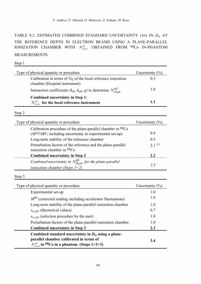
P. Andreo, P. Almond, O. Mattsson, A. Nahum, M. Roos
60
pp
TABLE 9.2. ESTIMATED COMBINED STANDARD UNCERTAINTY (1σ) IN Dw AT THE REFERENCE DEPTH IN ELECTRON BEAMS USING A PLANE-PARALLEL IONIZATION CHAMBER WITH OBTAINED FROM 60Co IN-PHANTOM
MEASUREMENTS airDN ,
Step 1
Type of physical quantity or procedure Uncertainty (%) Calibration in terms of NK of the local reference ionization chamber (Hospital instrument)
0.5
Interaction coefficients (km, katt, g) to determine ND,airref 1.0
Combined uncertainty in Step 1: for the local reference instrument ref
airDN ,
1.1
Step 2
Type of physical quantity or procedure Uncertainty (%)
Calibration procedure of the plane-parallel chamber in 60Co (Mref/Mpp, including uncertainty in experimental set-up)
0.4
Long-term stability of the reference chamber 0.5 Perturbation factors of the reference and the plane-parallel ionization chamber in 60Co
2.1 (1)
Combined uncertainty in Step 2 2.2 Combined uncertainty in N for the plane-parallel ionization chamber (Steps 1+2)
D,airpp
2.5
Step 3
Type of physical quantity or procedure Uncertainty (%) Experimental set-up 1.0
Mpp (corrected reading including accelerator fluctuations) 1.0
Long-term stability of the plane-parallel ionization chamber 1.0 sw,air (theoretical values) 0.7 sw,air (selection procedure by the user) 1.0 Perturbation factors of the plane-parallel ionization chamber 1.0 Combined uncertainty in Step 3 2.3 Combined standard uncertainty in Dw using a plane-parallel chamber calibrated in terms of
in 60Co in a phantom (Steps 1+2+3) ppairDN ,
3.4

IAEA Code of Practice for plane-parallel ionization chambers
Notes for Table 9.2.
(1) This estimation combines the uncertainty of pwallref from Andreo [19] with that of
pwallpp from Rogers [48] together with the chamber to chamber variations by different
manufacturers measured by Kosunen et al [50], all at 60Co gamma-rays. The uncertainty in the positioning of the effective point of measurement for the reference chamber or the alternative displacement factor is approximately 0.5% [40].
61

P. Andreo, P. Almond, O. Mattsson, A. Nahum, M. Roos
62
pp
TABLE 9.3. ESTIMATED COMBINED STANDARD UNCERTAINTY (1σ) IN Dw AT THE REFERENCE DEPTH IN ELECTRON BEAMS USING A PLANE-PARALLEL IONIZATION CHAMBER WITH OBTAINED FROM A 60Co IN-AIR
MEASUREMENT airDN ,
Step 1
Type of physical quantity or procedure Uncertainty (%) Calibration of the SSDL working standard 0.5 (1) Intercomparison of the working standard with the plane-parallel chamber
0.5 (2)
Combined uncertainty in Step 1: NK for the plane-parallel ionization chamber
0.7
Step 2
Type of physical quantity or procedure Uncertainty (%) Interaction coefficients (km, katt, g) to determine ND,air 2.5 (3) Combined uncertainty in Step 2 2.5 Combined uncertainty in N for the plane-parallel ionization chamber (Step 1+2)
D,airpp
2.6
Step 3
Type of physical quantity or procedure Uncertainty (%) Experimental set-up 1.0
Mpp (corrected reading including accelerator fluctuations) 1.0
Long-term stability of the plane-parallel ionization chamber 1.0 sw,air (theoretical values) 0.7 sw,air (selection procedure by the user) 1.0 Perturbation factors for the plane-parallel ionization chamber 1.0 Combined uncertainty in Step 3 2.3 Combined standard uncertainty in Dw using a plane-parallel chamber calibrated in terms of
in 60Co in air (Steps 1+2+3) ppairDN ,
3.5

IAEA Code of Practice for plane-parallel ionization chambers
63
Notes for Table 9.3
(1) The combined uncertainty for the working standard at the secondary standard dosimetry laboratory is the average of that given in TRS-277 (0.7%) and the value quoted by Grindborg et al (0.3%) for an SSDL in the IAEA/WHO network [117].
(2) The increased uncertainty in the intercomparison of the plane-parallel chamber with the working standard reflects the difficulty of positioning and aligning plane-parallel chambers in air for these measurements.
(3) This value represents an estimated average limit and is based upon the survey made by Rogers [48] of experimental values and uncertainties in the Monte-Carlo calculated values, and in the chamber-to-chamber variations by different manufacturers measured by Kosunen et al [50]. The maximum deviations reported in Ref. [50] for the experimental km katt values were 1.7% and 3.6% for NACP-I and Calcam-I chambers, respectively; for the Calcam-II this was 2.1%.

P. Andreo, P. Almond, O. Mattsson, A. Nahum, M. Roos
9.2. ESTIMATION BASED ON ND,w CALIBRATION
For ND,w-based determinations of absorbed dose to water, the most common method
for the calibration of a plane-parallel ionization chamber is its comparison in a 60Co beam
against a cylindrical chamber with a known . ND,w,Coref
The calibration chain, from the determination of absorbed dose to water using the
reference quality 60Co at the PSDL to the measurement of absorbed dose with a plane-parallel
chamber at a reference depth at the electron user’s beam, is also divided into the three steps
shown schematically in Fig. 9.4, along with the equations that apply at each step. The details
in the determination of Dw at the PSDL and the transfer to the SSDL are not shown.
Step 1 in the measurement chain starts with the realisation of absorbed dose to water
in the 60Co gamma ray beam at the PSDL and ends with the determination of the local
standard of absorbed dose to water; the determination of the calibration factor of the local
reference chamber, N is included in this level. Step 2 (Section 6.3) is the determination
of the absorbed dose to water calibration factor for the plane-parallel chamber by
intercomparison with the local reference instrument in 60Co at the SSDL or at the Hospital,
. Step 3 (Eq. 7.5) is the absorbed dose determination at the reference depth in a water
phantom using the calibrated plane-parallel chamber in electron beams; this is now different
from Step 3 with the determinations as it involves the kQ factor. The uncertainties in
the three steps are given in Table 9.4. Their quadratic sum yields a combined standard
uncertainty of 3.4% which is slightly larger than in the electron-beam ND,air procedure but is
of the same order as in the 60Co in-phantom calibration. This is mainly due to the
contribution of the uncertainty of the wall perturbation effects in 60Co of the plane-parallel
chambers (see Table 9.2).
D,w,Coref
ND,airpp
ND,w,Copp
If the plane-parallel ionization chamber is calibrated directly against a primary
standard of absorbed dose to water in 60Co the plane-parallel chamber is the local reference.
In this case part of Step 1 and the complete Step 2 do not contribute to the dosimetry chain.
This approach, however, does not decrease by more than a tenth of a percent the stated final
uncertainty in the absorbed dose determination in electrons because of the large contribution
of pwall in 60Co to the factor kQ.
64
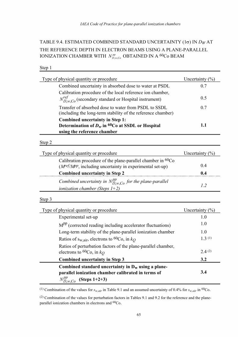
IAEA Code of Practice for plane-parallel ionization chambers
65
pp
TABLE 9.4. ESTIMATED COMBINED STANDARD UNCERTAINTY (1σ) IN DW AT THE REFERENCE DEPTH IN ELECTRON BEAMS USING A PLANE-PARALLEL IONIZATION CHAMBER WITH OBTAINED IN A 60Co BEAM CowDN ,,
Step 1
Type of physical quantity or procedure Uncertainty (%) Combined uncertainty in absorbed dose to water at PSDL 0.7 Calibration procedure of the local reference ion chamber,
(secondary standard or Hospital instrument) ND,w,Coref
0.5
Transfer of absorbed dose to water from PSDL to SSDL (including the long-term stability of the reference chamber)
0.7
Combined uncertainty in Step 1: Determination of Dw in 60Co at SSDL or Hospital using the reference chamber
1.1
Step 2
Type of physical quantity or procedure Uncertainty (%) Calibration procedure of the plane-parallel chamber in 60Co (Mref/Mpp, including uncertainty in experimental set-up)
0.4
Combined uncertainty in Step 2 0.4
Combined uncertainty in for the plane-parallel ionization chamber (Steps 1+2)
ND,w,Copp
1.2
Step 3
Type of physical quantity or procedure Uncertainty (%) Experimental set-up 1.0
Mpp (corrected reading including accelerator fluctuations) 1.0
Long-term stability of the plane-parallel ionization chamber 1.0 Ratios of sw,air, electrons to 60Co, in kQ 1.3 (1) Ratios of perturbation factors of the plane-parallel chamber, electrons to 60Co, in kQ
2.4 (2)
Combined uncertainty in Step 3 3.2 Combined standard uncertainty in Dw using a plane-parallel ionization chamber calibrated in terms of
(Steps 1+2+3) ND,w,Copp
3.4
(1) Combination of the values for sw,air in Table 9.1 and an assumed uncertainty of 0.4% for sw,air in 60Co. (2) Combination of the values for perturbation factors in Tables 9.1 and 9.2 for the reference and the plane-parallel ionization chambers in electrons and 60Co.

P. Andreo, P. Almond, O. Mattsson, A. Nahum, M. Roos
Figure Captions to Section 9.
66
ref
pp
ref
pp
pp
Fig. 9.1 Calibration chain for a plane-parallel chamber for the preferred method described in Section 5.3. Step 1 is the calibration and determination of for the reference chamber starting with the determination of the air kerma standard at the primary standard dosimetry laboratory. Step 2 is the determination of by comparison with high energy electrons. Step 3 is the use of the chamber to measure absorbed dose to water in the user's electron beam. The appropriate equations are put beside each step. ∏
iKi is the product of factors that account for water-vapour
content of the air, ionization recombination losses, stem scatter, correction to zero-wall thickness, etc [123].
ND,air
ND,air
Fig. 9.2 Calibration chain for a plane-parallel chamber for a calibration at "depth" in a phantom described in Section 5.4.1. Step 1 is the calibration and determination of
for the reference chamber starting with the determination of the air kerma
standard at the primary standard dosimetry laboratory. Step 2 is the determination of by comparison with 60Co gamma rays, at depth in a phantom. Step 3 is
the use of the chamber to measure absorbed dose to water in the user's electron beam. The appropriate equations are put beside each step.
ND,air
ND,pp
air
Fig. 9.3 Calibration chain for a plane-parallel chamber for calibration measurements free in-air as described in Section 5.4.2. Step 1 is the calibration and determination of NK
for the plane-parallel chamber starting with determination of the air kerma standard at the primary standard dosimetry laboratory. Step 2 is the determination of
by calculation for NK. Step 3 is the use of the chamber to measure absorbed dose to water in the user's electron beam. The appropriate equations are put beside each step
ND,air
Fig. 9.4 Calibration chain for a plane-parallel chamber for calibration against an absorbed dose standard described in Section 6.3. Step 1 is the calibration and determination of by comparison with 60Co gamma rays at depth in a water phantom.
Step 3 is the use of the chamber to measure absorbed dose to water in the user's electron beam. The appropriate equations are put beside each step.
ND,w,Co

IAEA Code of Practice for plane-parallel ionization chambers
67
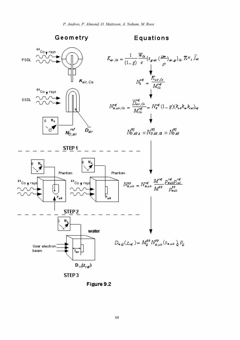
P. Andreo, P. Almond, O. Mattsson, A. Nahum, M. Roos
68

IAEA Code of Practice for plane-parallel ionization chambers
69

P. Andreo, P. Almond, O. Mattsson, A. Nahum, M. Roos
70