the synergytm door a new approach to - autosteel/media/files/autosteel/great designs in steel... ·...
TRANSCRIPT

w w w . a u t o s t e e l . o r g
The SynergyTM Door – A New Approach to
Lightweight Steel Doors
Paul Schurter, Tim Lim, ArcelorMittal
Mansour Mirdamadi, Dow Automotive

w w w . a u t o s t e e l . o r g
Outline
• Background
• Approach
• Structural Performance Targets
• SynergyTM Door Concept, Performance, Cost
• Adhesives Investigation
• Summary and Conclusions
Slide 1
w w w . a u t o s t e e l . o r g
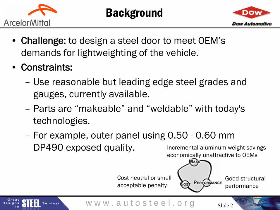
• Challenge: to design a steel door to meet OEM’s
demands for lightweighting of the vehicle.
• Constraints:
– Use reasonable but leading edge steel grades and
gauges, currently available.
– Parts are “makeable” and “weldable” with today's
technologies.
– For example, outer panel using 0.50 - 0.60 mm
DP490 exposed quality.
Background
Incremental aluminum weight savings
economically unattractive to OEMs
Cost neutral or small
acceptable penalty Good structural
performance
Slide 2

w w w . a u t o s t e e l . o r g
SynergyTM Lightweight Steel Door:
Innovative Concept
• Clean sheet design - 3G (Geometry,
Grade, Gauge) optimization considering
6 load cases simultaneously
• Revolutionary, not evolutionary design
concept
• Matches aluminum mass at ~ 30%
lower cost
• Uses structural adhesives
• Concept can be applied to open or
closed inner designs
• All grades and gauges currently
available
• Patent applied for
Slide 3
w w w . a u t o s t e e l . o r g
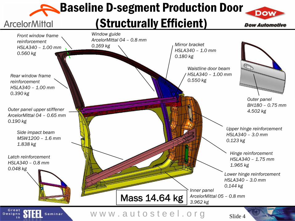
Baseline D-segment Production Door
(Structurally Efficient)
Outer panel
BH180 – 0.75 mm
4.502 kg
Hinge reinforcement
HSLA340 – 1.75 mm
1.965 kg
Inner panel
ArcelorMittal 05 – 0.8 mm
3.962 kg
Upper hinge reinforcement
HSLA340 – 3.0 mm
0.123 kg
Lower hinge reinforcement
HSLA340 – 3.0 mm
0.144 kg
Side impact beam
MSW1200 – 1.6 mm
1.838 kg
Outer panel upper stiffener
ArcelorMittal 04 – 0.65 mm
0.190 kg
Waistline door beam
HSLA340 – 1.00 mm
0.550 kg
Front window frame
reinforcement
HSLA340 – 1.00 mm
0.560 kg
Rear window frame
reinforcement
HSLA340 – 1.00 mm
0.390 kg
Window guide
ArcelorMittal 04 – 0.8 mm
0.169 kg Mirror bracket
HSLA340 – 1.0 mm
0.180 kg
Latch reinforcement
HSLA340 – 0.8 mm
0.048 kg
Mass 14.64 kg
Slide 4
w w w . a u t o s t e e l . o r g
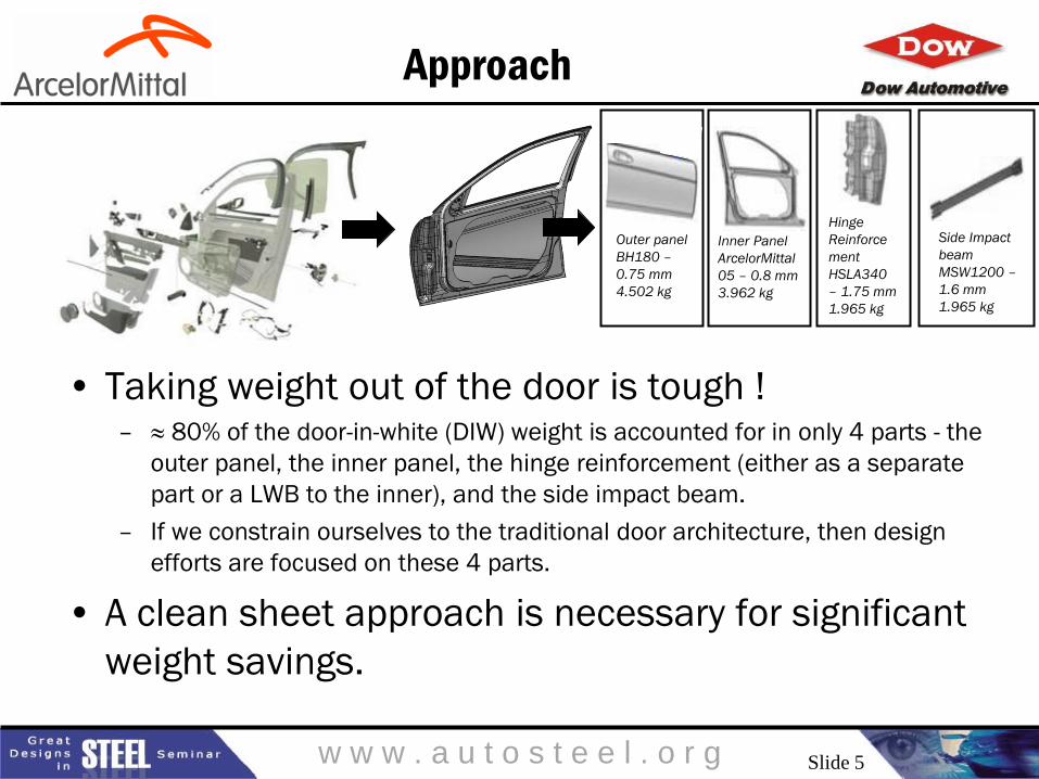
Approach
• Taking weight out of the door is tough ! – ≈ 80% of the door-in-white (DIW) weight is accounted for in only 4 parts - the
outer panel, the inner panel, the hinge reinforcement (either as a separate
part or a LWB to the inner), and the side impact beam.
– If we constrain ourselves to the traditional door architecture, then design
efforts are focused on these 4 parts.
• A clean sheet approach is necessary for significant
weight savings.
Side Impact
beam
MSW1200 –
1.6 mm
1.965 kg
Hinge
Reinforce
ment
HSLA340
– 1.75 mm
1.965 kg
Inner Panel
ArcelorMittal
05 – 0.8 mm
3.962 kg
Outer panel
BH180 –
0.75 mm
4.502 kg
Slide 5

w w w . a u t o s t e e l . o r g
3G Optimization Methodology
Baseline
Calibration
Design Space
Definition
14.6 kg
Define
structural
targets /
requirements.
FEA of the
Baseline
Designable
Volume
Topology
Optimization
Parameterized
Model
3G Design
Optimization
Concept
Design
Maximize
design
freedom:
Account for
window drop.
“Check” for all
other
hardware.
Primary
Design Envelope
Load path
studies,
defining
important
structures
from topology.
Header Rigidity
Beltline Rigidity
Torsion Rigidity
Door Sag
Door Overload
FMVSS214
0%
2%
4%
6%
8%
10%
12%
4 47 8 1243 44 45
48 49 5054
51 52 5355 46 56
Loadcase
Percentage of Total Loadcase Force
Section Number
MAIN STRUCTURAL SUB-SYSTEMS OF RAW TOPOLOGY MODEL LOADPATH MAPPING
Header Rigidity
Beltline Rigidity
Torsion Rigidity
Door Sag
Door Overload
FMVSS214
Parameterized
Design Envelope
Define and
parameterize
door
structure.
Optimized
Design
7.8 kg
Theoretical
minimum
weight door
disregarding
manufacturing
and material
constraints.
Concept
Design
10.5 kg
Considering
manufacturing
and material
constraints.
Slide 6

w w w . a u t o s t e e l . o r g
Parameterized model
Cross Sections can change
shape and size within
defined package space
Beams can translate
LWB lines can translate
Slide 7

w w w . a u t o s t e e l . o r g
Side impact
FMVSS214S
Imposed displacement
Pole impactor 450 mm/80 ms
Requirements At 152 mm >10kN
At 304 mm >16kN
At 457 mm >37kN
Crash
load case
Door Performance Targets (D-segment)
Door Beltline beam
Load path Sub system model
Imposed displacement
Requirements
Peak load >60kN
Also ≈ > 55 Hz modal requirement
Slide 8

w w w . a u t o s t e e l . o r g
SynergyTM Door Concept: Design Highlights
A
A Section AA
Baseline Door Synergy DoorTM Concept
Impact
beam
Glass drop
Alum. Module
Outer
Inner
InnerModule
Ext.
Outer
Hot Stamped
Beams and
Inner
Module extension replaces the traditional inner, but is less than half of the normal draw depth.
Bonding of the inner structure to the outer eliminates the need for a traditional impact beam.
SynergyTM Door Concept
Slide 9
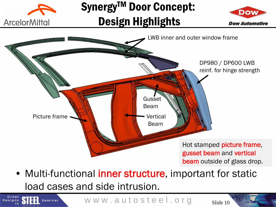
w w w . a u t o s t e e l . o r g
LWB inner and outer window frame
DP980 / DP600 LWB
reinf. for hinge strength
Hot stamped picture frame,
gusset beam and vertical
beam outside of glass drop.
Picture frame Vertical
Beam
Gusset
Beam
SynergyTM Door Concept:
Design Highlights
• Multi-functional inner structure, important for static
load cases and side intrusion.
Slide 10

w w w . a u t o s t e e l . o r g
SynergyTM Door Concept:
Design Highlights
Inner window frame extends into the inner
“picture frame” for better stiffness
Picture frame
Slide 11
w w w . a u t o s t e e l . o r g
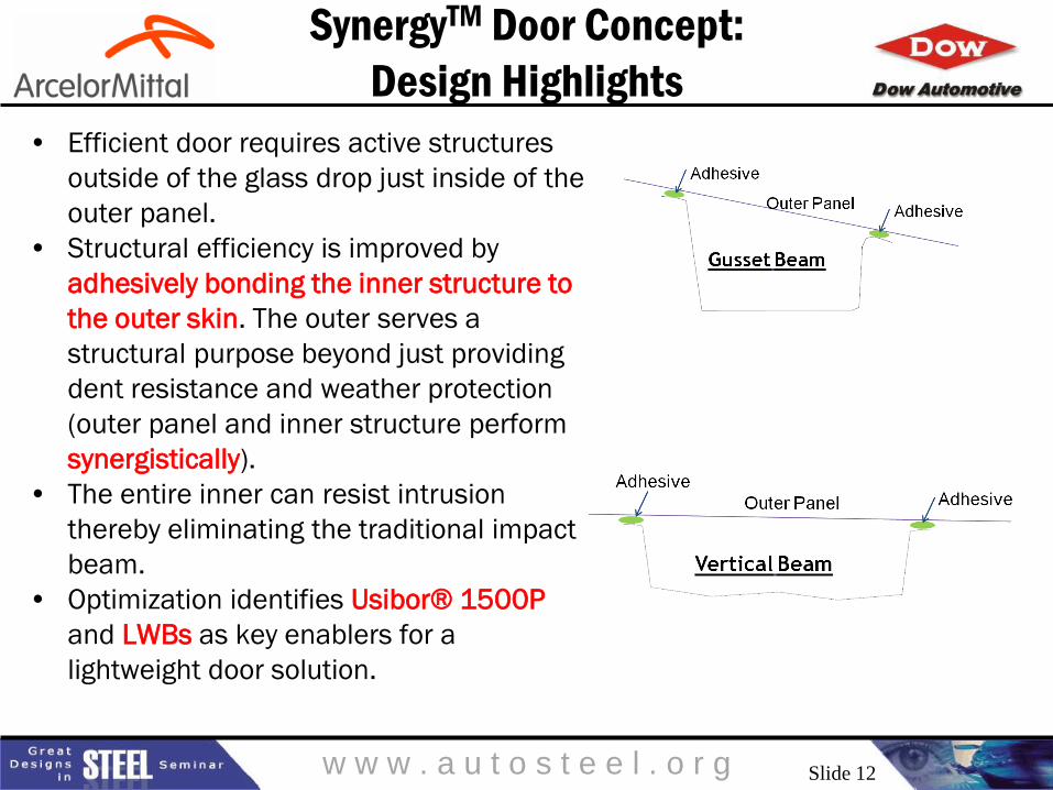
SynergyTM Door Concept:
Design Highlights
• Efficient door requires active structures
outside of the glass drop just inside of the
outer panel.
• Structural efficiency is improved by
adhesively bonding the inner structure to
the outer skin. The outer serves a
structural purpose beyond just providing
dent resistance and weather protection
(outer panel and inner structure perform
synergistically).
• The entire inner can resist intrusion
thereby eliminating the traditional impact
beam.
• Optimization identifies Usibor® 1500P
and LWBs as key enablers for a
lightweight door solution.
Slide 12
w w w . a u t o s t e e l . o r g
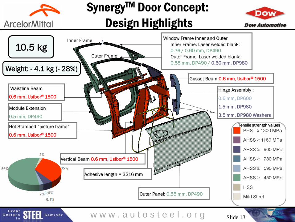
SynergyTM Door Concept:
Design Highlights
Vertical Beam 0.6 mm, Usibor® 1500
Waistline Beam
0.6 mm, Usibor® 1500
Module Extension
0.5 mm, DP490
Outer Panel: 0.55 mm, DP490
Window Frame Inner and Outer
Inner Frame, Laser welded blank:
0.76 / 0.60 mm, DP490
Outer Frame, Laser welded blank:
0.55 mm, DP490 / 0.60 mm, DP980
10.5 kg
Weight: - 4.1 kg (- 28%)
Outer Frame
Inner Frame
Gusset Beam 0.6 mm, Usibor® 1500
Hinge Assembly :
0.6 mm, DP600
1.5 mm, DP980
3.5 mm, DP980 Washers
Adhesive length = 3216 mm
Hot Stamped “picture frame”
0.6 mm, Usibor® 1500
Tensile strength values
Slide 13

w w w . a u t o s t e e l . o r g
SynergyTM Door Concept:
Design Highlights
• The entire inner structure resists intrusion thereby
eliminating the traditional impact beam
Note: Adhesive properties and
Usibor® 1500 fracture are modeled
(no fracture observed).
FMVSS static side intrusion
Average Force 2442 lbf vs.
target 2250 lbf in first 6 in.
Slide 14

w w w . a u t o s t e e l . o r g
Close /below target
Performance Results SynergyTM Door Values
STATIC Door Sag 1.5 mm (door only)
Wind Overload 3.8 deg. opening
STIFFNESS
Torsional Stiffness 500 Nm / deg rotation
Mid position Frame Stiffness 4.9 mm
Rear position Frame Stiffness 3.0 mm
Beltline Stiffness 1.5 mm
First Mode 54.1 Hz
CRASH FMVSS214S Side Impact 2442 lbf
(first 6 inches only)
Dent Resistance 133 lbf
Oil Canning 4.0 mm @ 90 N Load
SynergyTM Door Concept:
Structural and Weight Performance* Performance Ratings
10.5 kg Weight: - 4.1 kg (- 28%)
Above target
Close /at target Below target
Slide 15
* With BETAMATE 18XX adhesive

w w w . a u t o s t e e l . o r g
SynergyTM Door Concept Costs
$25 $21
$13 $30
$18
$18
$0
$10
$20
$30
$40
$50
$60
$70
$80
Baseline Synergy™ Door
Co
st
pe
r D
oo
r
Assembly
Forming
Materials$56
$69
Note: Material cost inputs as of July 2013
Cost penalty of
SynergyTM Door:
~ $3 per kg saved
Cost penalty of
aluminum door:
~ $10 per kg saved
Camanoe Associates Annual Production Volume = 200,000 vehicles/year
14.64 kg 10.5 kg
Slide 16

w w w . a u t o s t e e l . o r g
Adhesives Investigation
Slide 17

w w w . a u t o s t e e l . o r g
Adhesive Portfolio
Selection Considerations
• Assembly
requirements
• Substrates bonded
• Substrate coatings
• Cure profile
• Functional
performance
• Body shop, trim shop
• Manufacturing
process
Slide 18
w w w . a u t o s t e e l . o r g
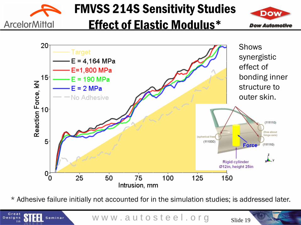
FMVSS 214S Sensitivity Studies
Effect of Elastic Modulus*
* Adhesive failure initially not accounted for in the simulation studies; is addressed later.
Shows
synergistic
effect of
bonding inner
structure to
outer skin.
Slide 19

w w w . a u t o s t e e l . o r g
Adhesive Coupon Level Studies
Substrate thickness
DP490 0.68 mm
USIBOR 1500 1.56 mm
Results
• Lap-shear strength of similar material
substrates bonding directly related to
bulk adhesive mechanical properties,
BETAMATE 73305 > BETAMATE 14XX
> BETAMATE 18XX
• Low modulus BETAMATE 18XX shows
superior performance for T-Peel, WIP,
and lap-shear strength for dissimilar
material substrate testing, while
minimizing the risk of read through.
Slide 20
w w w . a u t o s t e e l . o r g
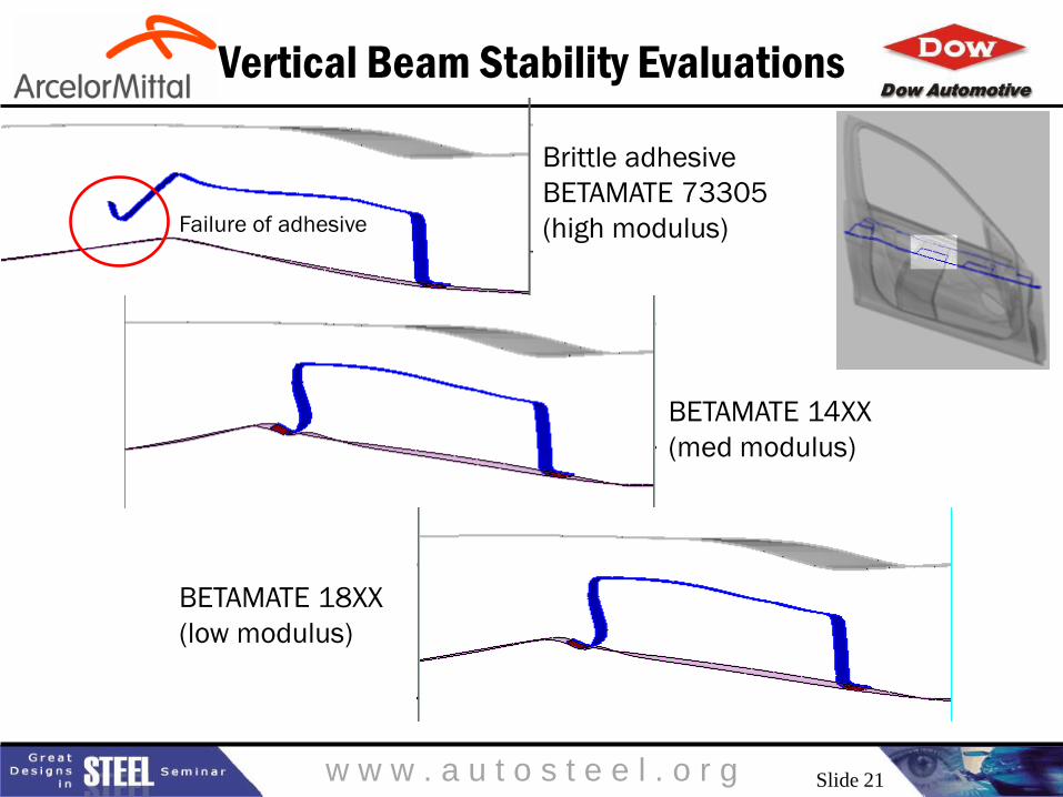
Vertical Beam Stability Evaluations
Brittle adhesive
BETAMATE 73305
(high modulus)
BETAMATE 14XX
(med modulus)
BETAMATE 18XX
(low modulus)
Failure of adhesive
Slide 21

w w w . a u t o s t e e l . o r g
Sensitivity of Adhesive to FMVSS 214S
(Considering Cohesive Failure)
(Target 2250 lbf)
• BETAMATE grades
– Tensile properties of BM73305 >
BM14XX > BM18XX
• Key conclusions
– Without BETAMATE adhesives,
FMVSS 214S side impact
requirement is not met.
– BETAMATE 73305 is not able to
provide sufficient ductility, vertical
door beam flange separates from
door outer skin (cohesive failure).
– BETAMATE 18XX shows that it can
provide sufficient strength in
meeting the FMVSS 214S
requirements; performs better than
the other two adhesives considered.
– Confirms that the outer skin serves
a structural purpose and performs
synergistically with the inner
structure to resist side intrusion.
Slide 22
w w w . a u t o s t e e l . o r g
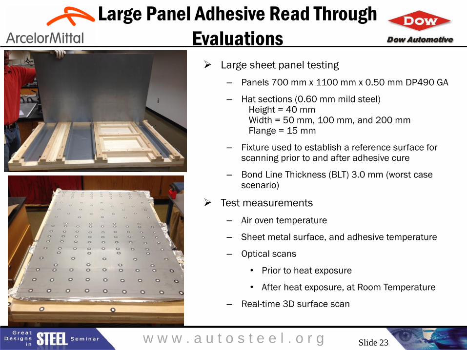
Large Panel Adhesive Read Through
Evaluations
Large sheet panel testing
– Panels 700 mm x 1100 mm x 0.50 mm DP490 GA
– Hat sections (0.60 mm mild steel) Height = 40 mm Width = 50 mm, 100 mm, and 200 mm Flange = 15 mm
– Fixture used to establish a reference surface for scanning prior to and after adhesive cure
– Bond Line Thickness (BLT) 3.0 mm (worst case scenario)
Test measurements
– Air oven temperature
– Sheet metal surface, and adhesive temperature
– Optical scans
• Prior to heat exposure
• After heat exposure, at Room Temperature
– Real-time 3D surface scan
Slide 23

w w w . a u t o s t e e l . o r g
Large Panel Read Through Evaluations
BETAMATE 14XX (med modulus)
BETAMATE 18XX (low modulus) BETAMATE 73305 (high modulus)
Curvature fringe plot
mm-1
Visible threshold is a
change in curvature of
2.0E-4 mm-1
No observable curvature pattern for low and
medium modulus adhesives after curing.
Slide 24
w w w . a u t o s t e e l . o r g
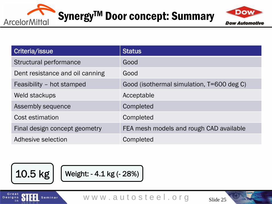
SynergyTM Door concept: Summary
Criteria/issue Status
Structural performance Good
Dent resistance and oil canning Good
Feasibility – hot stamped Good (isothermal simulation, T=600 deg C)
Weld stackups Acceptable
Assembly sequence Completed
Cost estimation Completed
Final design concept geometry FEA mesh models and rough CAD available
Adhesive selection Completed
10.5 kg Weight: - 4.1 kg (- 28%)
Slide 25
w w w . a u t o s t e e l . o r g
Key Conclusions
• 3G optimization yielded a unique design concept
• Additional structure between outer skin and glass drop
• Adhesive bonding enables synergistic interaction of outer skin with the
new inner structure
• Outer skin now serves structural purpose
• Adhesive characteristics achieve structural requirements while
mitigating the risk of read through
• Mass approximately equivalent to aluminum
• Cost penalty of $3.00 per kg saved vs. $10.00 per kg saved for
aluminum
• Concept can be applied to open or closed inner designs
• All materials commercialized or ready for commercialization
• Collaboration enabled this advancement in technology
Slide 26

w w w . a u t o s t e e l . o r g
North American
Light Vehicle Metallic Material Trends
Great Designs in Steel is Sponsored by:
Use your web-enabled device to download the presentations from today’s event
PRESENTATIONS WILL BE AVAILABLE MAY 16