environmental protection agency - autosteel/media/files/autosteel/great designs in steel...•...
TRANSCRIPT

w w w . a u t o s t e e l . o r g
MY2017-2025 GHG Standard
for Light Duty Vehicles Mass Reduction
Hugh Harris
Environmental Protection Agency
w w w . a u t o s t e e l . o r g
1) Overview of MY 2017-2025 light-duty vehicle
GHG rule and Mid-Term Evaluation
2) Agency vehicle mass-reduction studies
3) EDAG presentation on the 2012 EPA full
vehicle mass reduction project – 2010
Toyota Venza
2
Outline

w w w . a u t o s t e e l . o r g
AGENDA ITEM #1
Overview of MY 2017-2025
Light Duty Vehicle GHG rule
3

w w w . a u t o s t e e l . o r g
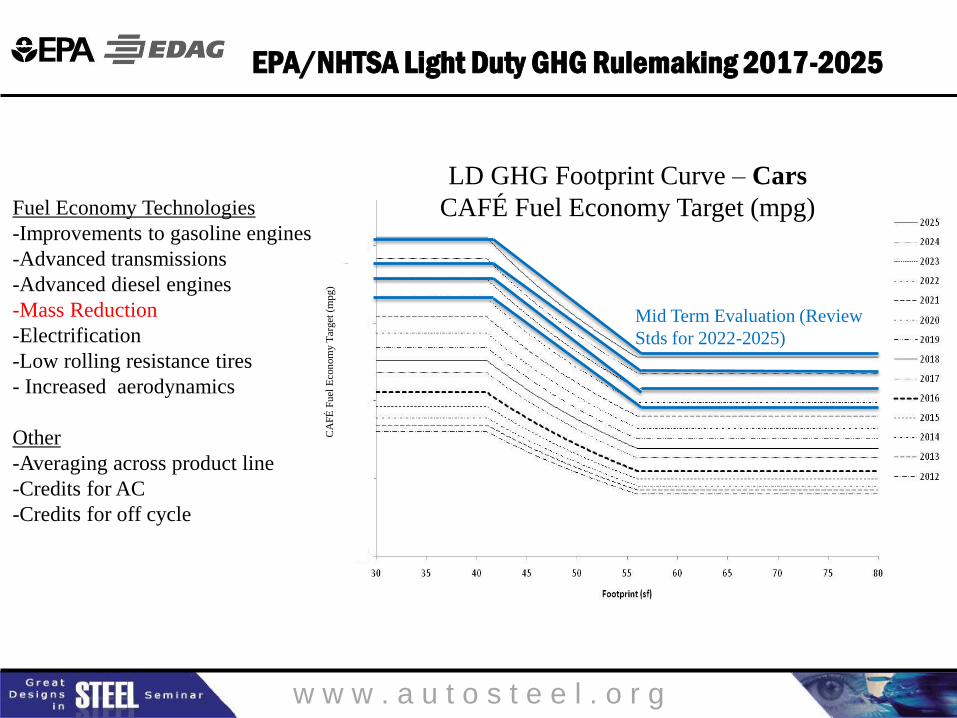
EPA/NHTSA Light Duty GHG Rulemaking 2017-2025
• Environmental Protection Agency (EPA), National Highway Traffic
Safety Administration (NHTSA) and California Air Resources Board
(CARB) worked together to develop a National Program of
harmonized regulations to reduce greenhouse gas emissions and
improve fuel economy of light-duty vehicles.
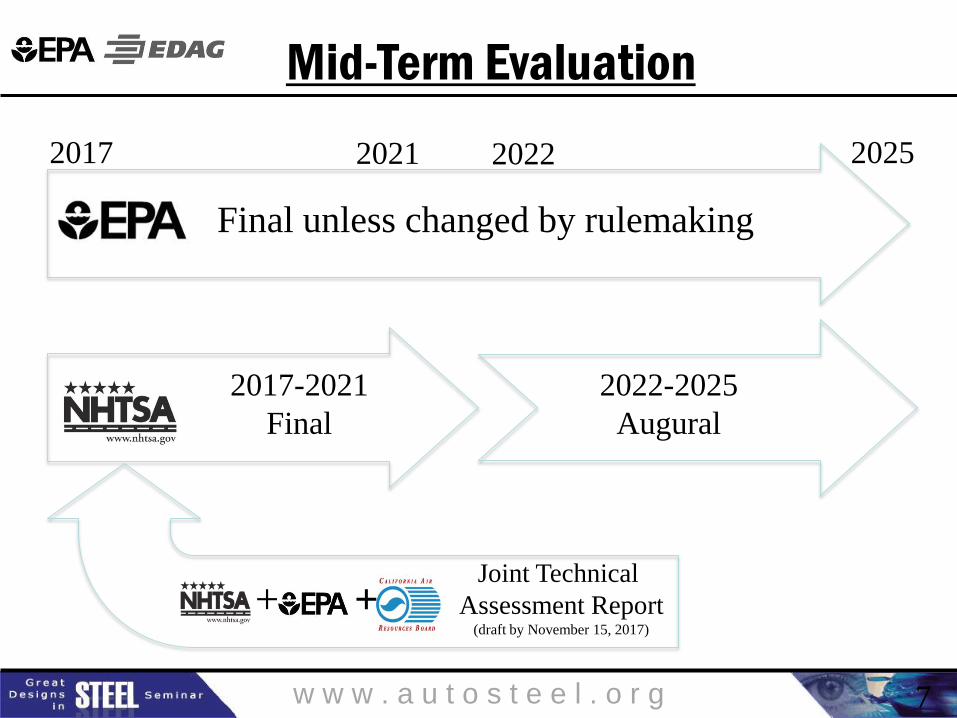
• Final Rulemaking to Establish 2017 and Later Model Years Light-
Duty Vehicle Greenhouse Gas Emissions and Corporate Average Fuel
Economy (CAFE) Standards are in effect for 2017-2021.
• A technical assessment is required to continue or modify the
standards for 2022-2025 vehicles.
4
w w w . a u t o s t e e l . o r g
EPA/NHTSA Light Duty GHG Rulemaking 2017-2025
LD GHG Footprint Curve – Cars
CAFÉ Fuel Economy Target (mpg)
CA
FÉ
Fu
el E
con
om
y T
arget
(m
pg) d
d
d
d
Mid Term Evaluation (Review
Stds for 2022-2025)
Fuel Economy Technologies
-Improvements to gasoline engines
-Advanced transmissions
-Advanced diesel engines
-Mass Reduction
-Electrification
-Low rolling resistance tires
- Increased aerodynamics
Other
-Averaging across product line
-Credits for AC
-Credits for off cycle

w w w . a u t o s t e e l . o r g
Rulemaking technology assumptions
• A wide range of technologies exist that can be used to reduce GHG/improve fuel economy.
– i.e. Advanced gasoline engines and transmissions, vehicle mass reduction, hybridization…
The standards are performance standards, not technology mandates. Manufacturers can choose any technologies to meet the standards. o The agencies simply project possible paths toward compliance.
• The EPA projects that most manufacturers could comply in 2025 by producing an overall fleet with:
– 8% mass reduction compared to model year 2008
– 66% advanced gasoline and diesel vehicles
– 26% mild hybrids
– 5% strong hybrids
– 3% plug-in hybrid electric vehicles and all electric vehicles
6
w w w . a u t o s t e e l . o r g
+ +
7
2017 2025 2021 2022
Final unless changed by rulemaking
2017-2021
Final
2022-2025
Augural
Joint Technical
Assessment Report (draft by November 15, 2017)
Mid-Term Evaluation
w w w . a u t o s t e e l . o r g
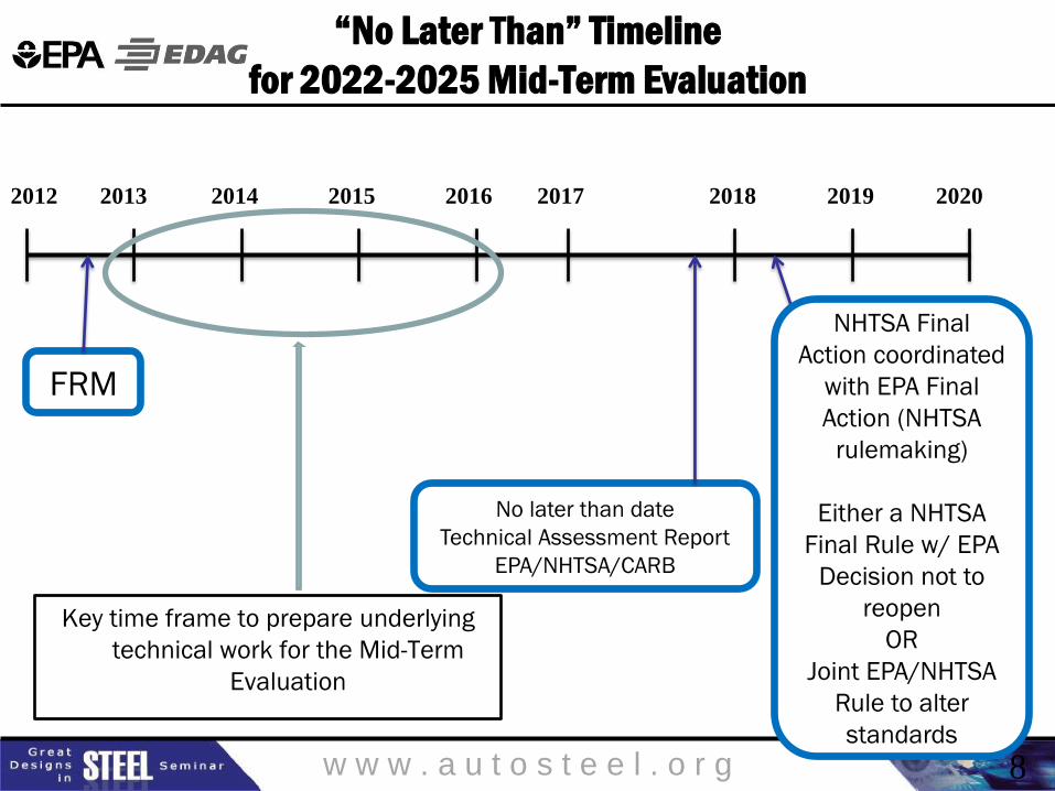
“No Later Than” Timeline
for 2022-2025 Mid-Term Evaluation
8
Key time frame to prepare underlying
technical work for the Mid-Term
Evaluation
FRM
2012 2013 2014 2015 2016 2020 2017 2018 2019
No later than date
Technical Assessment Report
EPA/NHTSA/CARB
NHTSA Final
Action coordinated
with EPA Final
Action (NHTSA
rulemaking)
Either a NHTSA
Final Rule w/ EPA
Decision not to
reopen
OR
Joint EPA/NHTSA
Rule to alter
standards

w w w . a u t o s t e e l . o r g
AGENDA ITEM #2
Agency mass-reduction studies
9

w w w . a u t o s t e e l . o r g
Whole-Vehicle Approach
to Mass Reduction
• The Agencies believe the full potential of mass reduction will
not be achieved with a focus only on individual parts
• OEMs will need to look at every system for opportunities and
look at vehicle “holistically”
• Mass decompounding of engine, transmission, driveline,
suspension, brakes, wheels……
1
0

w w w . a u t o s t e e l . o r g
Completed holistic vehicle studies
• 2010: CARB/Lotus Engineering initial paper study on Toyota Venza (Phase 1) – Low development (20%) vehicle
– High development (>30%) concept paper
– Hybrid powertrain study
• 2012: EPA/FEV (Phase 2) 2010 Midsize CUV low development (~20%) – Investigation of current mass reduction technologies
– Adding vehicle crash analysis for feasibility (BIW and closure)
– Additional CAE analysis to validate NVH, durability, stiffness, driveability, etc.
– More rigorous costing methodology – consistent with engine costing
• 2012: NHTSA/EDAG 20%+ MR study on Honda Accord – Similar goals in mind
– Dynamic (ADAMS model) analyses
• 2012: CARB (Phase 2) 2009 Midsize CUV high development vehicle (>30%) – Included Body in White and Closures only
– Longer time frame and advanced techniques
– Crash analysis and cost analysis included
** All Studies underwent rigorous peer reviews
1
1

w w w . a u t o s t e e l . o r g 1
2
Agency Holistic Vehicle Studies
CARB - 2010
Lotus Engineering, Toyota Venza
Low Dev
20% MR
High Dev
>30% MR
Hybrid PT
EPA – 2012
Toyota Venza
(FEV/EDAG)
NHTSA – 2012
Honda Accord
(EDAG)
CARB – 2012
Toyota Venza
(Lotus)
EPA – 2011-2014
Light Duty Truck
(FEV/EDAG)
CARB/Lotus Engineering
Toyota Venza (Phase 1)
3 reports in one
EPA/FEV released study on the
2010 Venza low development
vehicle (phase 2) – Full vehicle
NHTSA/EDAG released mass
reduction on Honda Accord -
Full vehicle/Glider
CARB continued study of
Venza high development
vehicle (Phase 2) – BIW only
All reports available online
EPA Truck study in progress

w w w . a u t o s t e e l . o r g
AGENDA ITEM #3
EDAG presentation on EPA Study
1
3

w w w . a u t o s t e e l . o r g
Full Vehicle Lightweight Designing Based on CAE Techniques
Javier Rodríguez
EDAG Inc.

w w w . a u t o s t e e l . o r g
Presentation Outline
1. Project Scope
• Mass reduction feasibility study
2. Project Initiation
• Establishment of the Baseline
3. Collaborative Optimization
• Collaboration Process Integration into the Optimization
4. Multidisciplinary Optimization
• Definition
5. Optimized Model
• Output
6. Methodology for the Study Work
• Output
7. References

w w w . a u t o s t e e l . o r g
1. Project Details
Mass Reduction Feasibility
The weight reduction and cost effects [4] of multiple lightweight designs were
analyzed and evaluated together using advanced optimization software and
engineering tools.
This presentation highlights the processes used in the evaluation of full vehicle
weight savings opportunities using advanced cooperative optimization computer-
aided engineering (CAE) tools
• Baselinevehicle2011HondaAccord
• Iden fylightweigh ngtechnologiesforMY2020modelyearvehicle
• Cost+/-10%ofcurrentbaselinevehicle’sMSRP
• Samevehicleperformanceandfunc onalityincludingsafety
• Allrecommendedtechnologiestobesuitablefor200,000annualproduc on,1Millionvehiclesover5years
• BaselineVehicle2011ToyotaVenza
• Onlytechnologiesandtechniquescurrentlyfeasibleformanufacturabilitywereconsidered
• Op onshadtobecosteffec veforaMY2017highvolumeproduc onvehicle
• ThevehicleNVHmodalcharacteris csandcrash/safetyperformancehadtobemaintained
• Thetotalcostimpactneededtobeminimal
NHTSA
EPA

w w w . a u t o s t e e l . o r g
Mass-Reduction Results: Net Incremental Direct Manufacturing Cost Impact by Vehicle System
17

w w w . a u t o s t e e l . o r g
2. Project Initiation
Establishment of the Baseline
Vehicle level CAE models for noise, vibration, and harshness (NVH) and crash were
built based on physical NVH and regulatory crash testing
The CAE load cases and performance criteria included:
– Structural strength (torsion, bending, and natural frequencies)
– Regulatory crash requirements (flat frontal impact FMVSS208/US NCAP,
40% offset frontal Euro NCAP; side impact FMVSS214; rear impact
FMVSS301; and roof crush resistance FMVSS216A/IIHS)
– Durability and Fatigue
– Vehicle Performance
– Should (predictive) costs for every option and variation [4]
The FEA model and simulation results of the baseline were correlated with physical
testing

w w w . a u t o s t e e l . o r g
2. Project Initiation
Establishment of the Baseline, Inputs, outputs & Tools

w w w . a u t o s t e e l . o r g
2. Project Initiation
Creation of the Baseline for the Optimization Process

w w w . a u t o s t e e l . o r g
Baseline Gauge Map
2. Project Initiation
Baseline Model: System Weights and Materials

w w w . a u t o s t e e l . o r g
Baseline Material Map
2. Project Initiation
Baseline Model: System Weights and Materials (Cont.)

w w w . a u t o s t e e l . o r g
Baseline
System Sub-system System-Mass(Kg)
DoorFrt 53.2
DoorRr 42.4
Hood 17.8
Tailgate 15
Fenders 6.8
Sub-Total 135.2
UnderbodyAssembly 40.2
FrontStruture 42
RoofAssembly 31.3
BodysideAssembly 161.9
LadderAssembly 102.6
Sub-Total 378
RadiatorVerticalSupport 0.7CompartmentExtra 4.4
ShockTowerXmbrPlates 3.1Sub-Total 8.2
BumperFrt 5.1
BumperRr 2.4
Sub-Total 7.5
TotalWeight 528.9
Closures
BIW
BIWExtra
Bumpers
Baseline Sub-Systems Weights
2. Project Initiation
Baseline Model: System Weights and Materials (Cont.)

w w w . a u t o s t e e l . o r g
Once the FEA model was
created, EDAG built the
baseline for the
multidisciplinary optimization
(MDO) model
The MDO is the tool used to
investigate weight
optimization opportunities
that will also meet
performance and cost criteria
BIWAnalysis
ClosuresAnalysis
PowertrainAnalysis
InteriorAnalysis
ChassisAnalysis
Inputs
FullVehicleAnalysisandCollabora veOp miza onVariables
Requirements
Costs
Variables
Requirements
Costs
Variables
Requirements
Costs
BodyStructureandClosuresDesignSpace
Matrix
2. Project Initiation
Baseline Model: Optimization Process

w w w . a u t o s t e e l . o r g
3. Collaborative Optimization
Collaborative Optimization Process
• FSVEngineeringReport• EDAGLightVehicle
• LWSSFTFuelTank
• AdvancedSteelBumper
EDAGExper se
• LotusReport• Tier1supplierbase• Misc.Lightweightcars• AudiInt.LightweightBody
ExternalInforma on
BIWAnalysis
ClosuresAnalysis
PowertrainAnalysis
InteriorAnalysis
ChassisAnalysis
Inputs
FullVehicleAnalysisandCollabora veOp miza onVariables
Requirements
Costs
Variables
Requirements
Costs
Variables
Requirements
Costs
BodyStructureandClosuresDesignSpace
Matrix
FEVExper se
ExternalInforma on

w w w . a u t o s t e e l . o r g
PossibleSolu onsPlotwith:
OpportunityversusCostsandWeight
BIWAnalysis
ClosuresAnalysis
PowertrainAnalysis
InteriorAnalysis
ChassisAnalysis
Inputs
FullVehicleAnalysisandCollabora veOp miza onVariables
Requirements
Costs
Variables
Requirements
Costs
Variables
Requirements
Costs
BodyStructureandClosuresDesignSpace
Matrix
3. Collaborative Optimization
Collaborative Optimization Process

w w w . a u t o s t e e l . o r g
PossibleSolu onsPlotwith:
OpportunityversusCostsandWeight
BIWAnalysis
ClosuresAnalysis
PowertrainAnalysis
InteriorAnalysis
ChassisAnalysis
Inputs
FullVehicleAnalysisandCollabora veOp miza onVariables
Requirements
Costs
Variables
Requirements
Costs
Variables
Requirements
Costs
BodyStructureandClosuresDesignSpace
Matrix
Collabora veOp miza onwherewedecomposedthedesignconceptprocessintomoremanageablepieces
FEA/ShouldCostsAnalysisconfirmtheoverallperformance
3. Collaborative Optimization
Collaborative Optimization Process

w w w . a u t o s t e e l . o r g
DesignVariables
Matrix0
• OverallVehicleWeight
Matrix1
• MaterialThickness
• MaterialSubs tu on
• JoiningTechnologies
• TailorBlankTechnology
Matrix2
• StructureRedesign
• ShapeChanges
• FutureManufacturingTechnologies
• Alterna veStructureConcepts
StructuralVaria ons
Proper es
Shape
DesignResponses
Linear(S ffness)andNon-linear(Crash)
Objec veand
Constraints
Objec ves(Weight
Reduc on)
Constraints(Costs)
Output
Op mumSolu ons
FullVehicleAnalysisandCollabora veOp miza on
4. Multidisciplinary Optimization
Overview

w w w . a u t o s t e e l . o r g
The model consisted of 484 parts, seven (7) load cases (Linear and Non-
linear) and one (1) should cost calculation
The design variables included 242 continuous variables for part thickness and
242 discrete variables for material grades, assigned to the identified parts
To reduce the number of variables:
– Load path analysis for each load case was conducted on the baseline
model to identify the necessary parts based on the criteria of higher
cross-section forces
– The gauge and grade variables of the right hand side BIW parts were
assigned as dependent variables to that of the left hand side parts
Minimum and maximum limits for each gauge variable were defined based on
manufacturing feasibility and tooling impact
DesignVariables
Matrix0
• OverallVehicleWeight
Matrix1
• MaterialThickness
• MaterialSubs tu on
• JoiningTechnologies
• TailorBlankTechnology
Matrix2
• StructureRedesign
• ShapeChanges
• FutureManufacturingTechnologies
• Alterna veStructureConcepts
StructuralVaria ons
Proper es
Shape
DesignResponses
Linear(S ffness)andNon-linear(Crash)
Objec veand
Constraints
Objec ves(Weight
Reduc on)
Constraints(Costs)
Output
Op mumSolu ons
4. Multidisciplinary Optimization
Design Variables

w w w . a u t o s t e e l . o r g
Based on EDAG expertise and input from other companies, including automotive
OEMs and Tier 1 suppliers, a design space matrix was generated with possible
structural variations including engineering costs estimates
Any idea included in the design matrix had to be feasible* for the vehicle and
capable of being in production for 2017 (EPA)
*Feasible idea = Currently in production in other vehicles
DesignVariables
Matrix0
• OverallVehicleWeight
Matrix1
• MaterialThickness
• MaterialSubs tu on
• JoiningTechnologies
• TailorBlankTechnology
Matrix2
• StructureRedesign
• ShapeChanges
• FutureManufacturingTechnologies
• Alterna veStructureConcepts
StructuralVaria ons
Proper es
Shape
DesignResponses
Linear(S ffness)andNon-linear(Crash)
Objec veand
Constraints
Objec ves(Weight
Reduc on)
Constraints(Costs)
Output
Op mumSolu ons
• FSVEngineeringReport• EDAGLightVehicle
• LWSSFTFuelTank
• AdvancedSteelBumper
EDAGExper se
• LotusReport• Tier1supplierbase• Misc.Lightweightcars• AudiInt.LightweightBody
ExternalInforma on
BIWAnalysis
ClosuresAnalysis
PowertrainAnalysis
InteriorAnalysis
ChassisAnalysis
Inputs
FullVehicleAnalysisandCollabora veOp miza onVariables
Requirements
Costs
Variables
Requirements
Costs
Variables
Requirements
Costs
BodyStructureandClosuresDesignSpace
Matrix
4. Multidisciplinary Optimization
Structural Variations

w w w . a u t o s t e e l . o r g
Several constraints and responses measured from different load cases were
considered in the optimization model
– Body in White (BIW) natural frequencies and specific dynamic stiffness
– Left and right vertical displacements for bending and torsion stiffness
– Pulse, foot intrusion, left, center and right toe pan intrusions for flat
frontal impact
– Pulse, foot intrusion, left, center and right toe pan intrusions for offset
frontal impact
– B-Pillar to seat centerline intrusion gap for side impact
– Rear zone deformations for rear impact
– Roof rail resistance force for roof crush
– BIW and Closures cost (using current mat database costs)
– Fatigue and components life (as a design confirmation)
– Vehicle Performance (Acceleration, R&H, etc.)
DesignVariables
Matrix0
• OverallVehicleWeight
Matrix1
• MaterialThickness
• MaterialSubs tu on
• JoiningTechnologies
• TailorBlankTechnology
Matrix2
• StructureRedesign
• ShapeChanges
• FutureManufacturingTechnologies
• Alterna veStructureConcepts
StructuralVaria ons
Proper es
Shape
DesignResponses
Linear(S ffness)andNon-linear(Crash)
Objec veand
Constraints
Objec ves(Weight
Reduc on)
Constraints(Costs)
Output
Op mumSolu ons
4. Multidisciplinary Optimization
Design Responses

w w w . a u t o s t e e l . o r g
The objective of the optimization was to minimize the total mass of the BIW and
Closures
Model performance was measured as a normalized value of the design
responses
Baseline model performance needed to be maintained or improved for the
solution to be to considered viable
BIW material cost constraints were also considered a critical parameter that also
had to be satisfied in order to deliver viable results
DesignVariables
Matrix0
• OverallVehicleWeight
Matrix1
• MaterialThickness
• MaterialSubs tu on
• JoiningTechnologies
• TailorBlankTechnology
Matrix2
• StructureRedesign
• ShapeChanges
• FutureManufacturingTechnologies
• Alterna veStructureConcepts
StructuralVaria ons
Proper es
Shape
DesignResponses
Linear(S ffness)andNon-linear(Crash)
Objec veand
Constraints
Objec ves(Weight
Reduc on)
Constraints(Costs)
Output
Op mumSolu ons
4. Multidisciplinary Optimization
Objectives and Constrains

w w w . a u t o s t e e l . o r g
A hybrid and adaptive algorithm called SHERPA (Heeds MDO) was chosen as
the optimization method. EDAG has also used this method in several previous
studies
Initially the optimization required more than 400 design evaluations.
Each feasible design was analyzed by the engineering team and “human”
input was always part of optimization process.
DesignVariables
Matrix0
• OverallVehicleWeight
Matrix1
• MaterialThickness
• MaterialSubs tu on
• JoiningTechnologies
• TailorBlankTechnology
Matrix2
• StructureRedesign
• ShapeChanges
• FutureManufacturingTechnologies
• Alterna veStructureConcepts
StructuralVaria ons
Proper es
Shape
DesignResponses
Linear(S ffness)andNon-linear(Crash)
Objec veand
Constraints
Objec ves(Weight
Reduc on)
Constraints(Costs)
Output
Op mumSolu ons
4. Multidisciplinary Optimization
Optimization Engine and Outputs

w w w . a u t o s t e e l . o r g
4. Multidisciplinary Optimization
Full Vehicle Process Overview

w w w . a u t o s t e e l . o r g
Optimized Gauge Map
5. Optimized Model
BIW Weights and Materials

w w w . a u t o s t e e l . o r g
Optimized Material Map
5. Optimized Model
BIW Weights and Materials (Cont.)
w w w . a u t o s t e e l . o r g
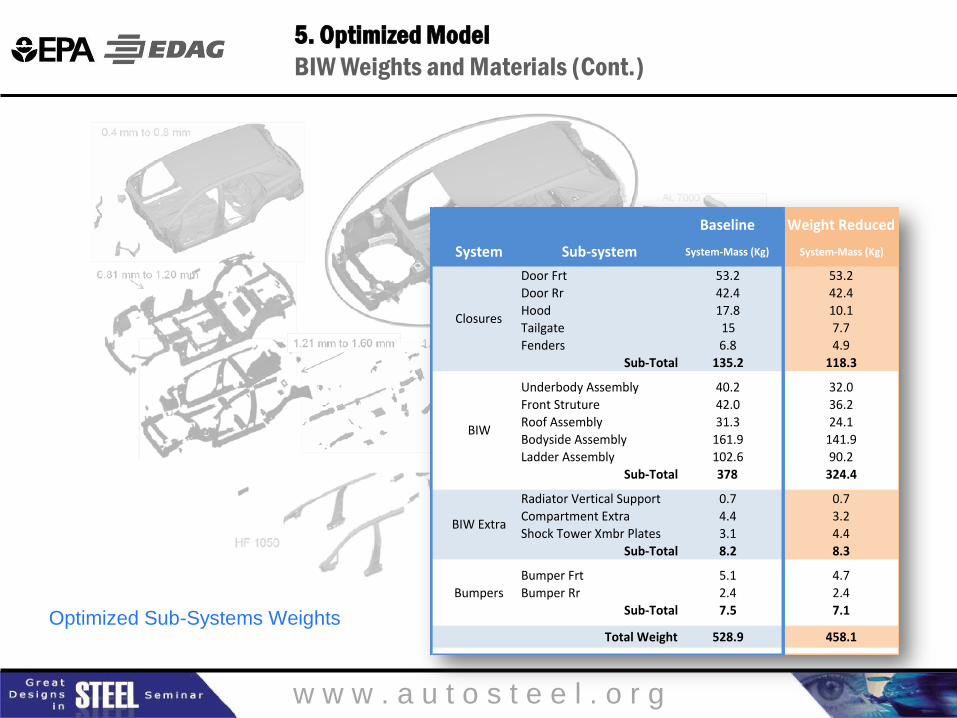
Optimized Sub-Systems Weights
Baseline WeightReduced
System Sub-system System-Mass(Kg) System-Mass(Kg)
DoorFrt 53.2 53.2DoorRr 42.4 42.4
Hood 17.8 10.1
Tailgate 15 7.7
Fenders 6.8 4.9
Sub-Total 135.2 118.3
UnderbodyAssembly 40.2 32.0
FrontStruture 42.0 36.2
RoofAssembly 31.3 24.1
BodysideAssembly 161.9 141.9LadderAssembly 102.6 90.2
Sub-Total 378 324.4
RadiatorVerticalSupport 0.7 0.7
CompartmentExtra 4.4 3.2
ShockTowerXmbrPlates 3.1 4.4
Sub-Total 8.2 8.3
BumperFrt 5.1 4.7
BumperRr 2.4 2.4
Sub-Total 7.5 7.1
TotalWeight 528.9 458.1
Closures
BIW
BIWExtra
Bumpers
5. Optimized Model
BIW Weights and Materials (Cont.)

w w w . a u t o s t e e l . o r g
For further information on results, please go to the technical papers [1,2,3]
These studies are an evolutionary implementation of advanced optimization
technologies including multidisciplinary concept design and collaborative
optimization.
The Advanced High Strength Steel (AHSS) materials and manufacturing
technologies proposed in the study are currently used in the automotive
industry.
The demonstrated mass reduction opportunities in the BIW utilizes existing
technologies and could be fully developed within the normal ‘product design
cycle’ using the current ‘design and development’ methods prevalent to the
automotive industry.
6. Methodology for the Study Work

w w w . a u t o s t e e l . o r g
[1] Regulations & Standards: Light-Duty
http://epa.gov/otaq/climate/regs-light-duty.htm
[2] FEV, “Light-Duty Vehicle Mass-Reduction and Cost Analysis – Midsize Crossover
Utility Vehicle “. July 2012, EPA Docket: EPA-HQ-OAR-2010-0799
[2] Joint Technical Support Document EPA-420-R-10-901, April 2012
http://epa.gov/otaq/climate/regulations/420r10901.pdf
[3] Final Rulemaking: Model Year 2012-2016 Light-Duty Vehicle Greenhouse
Gas Emissions Standards and Corporate Average Fuel Economy Standards
http://epa.gov/otaq/climate/regs-light-duty.htm#finalR
[4] ULSAB-AVC Cost Models
http://www.worldautosteel.org/projects/cost-models/
7. References
Contact Information:
Hugh Harris
EPA
Senior Engineer
Tel + 1 734 214 4705
Javier Rodriguez
EDAG Inc.
Director Vehicle Integration
Tel +1 248 577 4036
w w w . a u t o s t e e l . o r g
Great Designs in Steel is Sponsored by:
Use your web-enabled device to download the presentations from today’s event
PRESENTATIONS WILL BE AVAILABLE MAY 3