the super music triggered light show...
TRANSCRIPT

The Super Music Triggered Light Show ProjectFinal Project ReportDecember 8, 2000
E155
Mike Lane and Elizabeth Johansen
Abstract:
The aim of this project was to create a music-triggered set of strobe lights that would flash on the beat of anaudio input signal. The “beat” in music can be found by passing an audio signal through a low-pass filterand then looking at the relative amplitudes of the output. The 68HC11 was used to determine whether ornot a peak occurred, and then output a digital signal to the FPGA. The FPGA then generated three differentpseudo-random pulse sequences, which were used to trigger a series of two relays, which then triggered thethree strobe lights, which could theoretically be covered with red, green, and blue gels for an interestingeffect. The system, as it stands, behaves perfectly when given a square wave input with small duty cyclefrom a function generator. With audio input, the system detects the beats, but also strobes anomalouslyduring the audio input.

The Super Music Triggered Light Show Project
2
Introduction
Background
Many parties use strobe lights as a part of the dance floor lighting. Typically these
strobe lights are boring white lights that blink at a constant rate. The purpose of this
project is to make a system to control three strobe lights of three different colors to blink
with the beat of the music.
Specifications
The strobe system takes in a musical input from a CD player. The three strobes
(red, green, and blue colored when covered by different gels) flash in synch with the beat
of the music in a pseudo-random manner. This will cause either zero, one, two, or all
three strobes to be lit simultaneously, making the room appear black, red, orange, green,
blue, purple, or white during each beat of the music.
Method
The audio signal is an analog signal that is first put through a series of op-amps to
condition the signal. One of the op-amps is configured as a low-pass filter. The filter
increases the relative amplitude of the instruments used to keep the beat of dance music
(usually drums or a base guitar). The filtered and amplified signal is then converted to a
digital value by the 68HC11 EVB. The 68HC11 then produces a pulse over the parallel
port every time a beat is detected. The FPGA utility board takes in the beat pulse from the
68HC11 and uses the beat as a clock to generate three pseudo-random pulse sequences.
These pulse sequences are then fed to three series of two relays that, in turn, trigger the
three strobes (see Figure #1 for overall system diagram).

The Super Music Triggered Light Show Project
3
Figure #1: Overall System Block Diagram
Materials
? 68HC11 EVB
? Utility board with FPGA
? Protoboard
? Amplifier and filter
? 5-6V relays and 12V relays
? Strobe kits
Audio Input
Low Pass Filterand Amplifier
A/D Conversion
Beat Detection
Psudo Random Sequence Generation
Strobe Triggers
Strobes
68HC11 EVB
FPGA

The Super Music Triggered Light Show Project
4
New Hardware
The main new piece of hardware used in this project was a strobe light kit.
Triggering the strobes with a 5-volt source was not trivial, but not very complex. In the
original design of the kit, the strobes were triggered by charging a capacitor whose
positive lead was attached to a triac trigger. The triac would open when the capacitor
reached a certain voltage and this would ground the xenon tube trigger capacitor, causing
the tube to flash. Our task was to create a trigger that would act like a switch and
momentarily connect the trigger capacitor to ground.
After many failures at a purely electrical method, we discovered that a relay
would do exactly what we wanted. Unfortunately, there are no relays that can be
triggered with a 5 volt signal and handle the large instantaneous current flow to ground.
To solve this problem, we used two relays to trigger each strobe light. The first relay
triggered on 5 to 6 volts, but needed more current than the FPGA could provide, so we
used transistors in a configuration similar to that used to power the 7-segment display in
Lab 2. The input of the smaller relay was connected to ground, and the output connected
to the negative side of the trigger on the second relay. The positive side of the trigger on
the second relay was connected to a 12 volt source such that when the first relay closed
the second would also close, completing the connection to ground and cause the strobe
light to flash (see Figure# 2 for schematics).
The only drawback to this solution is that the larger relays made a loud clicking
noise from the contacts quickly opening and closing, though this should not be a
distraction when loud dance music is also playing. For future projects, one may want to
put a little research into a cheaper, fully electronic method of grounding the trigger
capacitor.

The Super Music Triggered Light Show Project
5
Schematics
Figure #2: Overall System Schematic
Figure #3: Schematics of Strobe with Points “A” and “B” HighlightedThe area crossed out refers to the trigger mechanism built into the strobe kit. Weremoved the trigger for the purposes of our system and replaced it with the relays.

The Super Music Triggered Light Show Project
6
Microcontroller Design
The Microcontroller is used to detect the peaks in the filtered, scaled, analog
audio signal. The algorithm (see Figure #4 for block diagram) operates with the
Figure #4: Microcontroller Block Diagram
idea that a “beat” is a signal of higher amplitude than the rest of the musical signal. The
signal enters through Port E7, which is configured to continuously perform analog to
digital conversions on the input. Digitized data samples are taken from the first address
storage location every 20ms. The sample rate was set in order to identify the peaks in the
input signal indicative of the beat as opposed to the smaller peaks in the signal not
indicative of beat. The DC offset of the input signal is subtracted from this new input
value. If the signal level is below the DC offset level, we take the absolute value of the
signal by finding the 2’s compliment and continue on. The new sample of the signal is
then compared to a running average. In our final algorithm, a peak is identified as a
value three times the amplitude of the running average. This value was determined by
observing the musical signal in Matlab, which showed that the filtered signal peaks were
generally 75% higher than the upper noise level below them. Looking at the average
level of the signal instead of the top edge of the signal, the peaks indicative of beat were
Analog Music Signal
+5VDCGND
0/5V signalindicative of beat
A/DConversion
CompareNew Valueto Running
Average
Add NewValue toRunningAverage
Output RoutineHigh for 10msLow for 140ms
Not a peak
Peak Detected

The Super Music Triggered Light Show Project
7
200% - 250% higher than the average signal level. Hence, the beat peaks can be said to
be three times the amplitude of the average signal level (see Figure #5 for image of audio
signal in Matlab).
Figure #5: Graph of Filtered Musical Input Amplitude v. Time Generated in Matlab*
*X-axis is in units of [# of samples], y-axis is in units of [digital amplitude]
Upon sensing a peak high enough to be considered a beat, the micro-controller outputs a
+5V signal from Port B, bit zero for 10ms; the amount of time needed to trigger the
strobe lights. It then puts out a zero from Port B, bit zero, for 140ms. The 10ms peak
time and 140ms wait time were set after examining several types of music using Matlab
and determining the maximum width of a beat peak to be 150ms. Hence, during the
150ms-long output routine, the running average is kept up to date, but the peak-detection
algorithm is not used because, within one beat, the signal oscillates up and down which
could be identified to be several beats in a row instead of one beat by our peak-detection
algorithm. After the output routine, the peak detection program resumes. Please Refer to
Appendix A for assembly code.
The Super Music Triggered Light Show Project
8
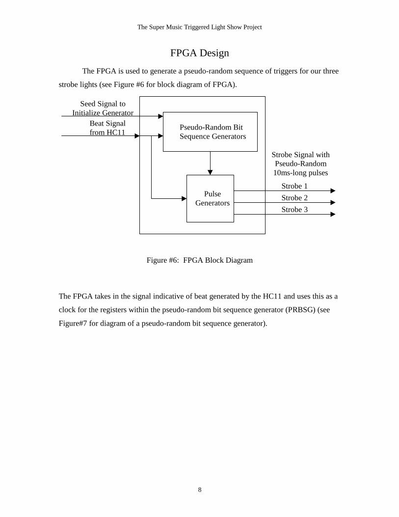
FPGA Design
The FPGA is used to generate a pseudo-random sequence of triggers for our three
strobe lights (see Figure #6 for block diagram of FPGA).
Figure #6: FPGA Block Diagram
The FPGA takes in the signal indicative of beat generated by the HC11 and uses this as a
clock for the registers within the pseudo-random bit sequence generator (PRBSG) (see
Figure#7 for diagram of a pseudo-random bit sequence generator).
Pseudo-Random BitSequence Generators
PulseGenerators
Beat Signalfrom HC11
Strobe Signal withPseudo-Random10ms-long pulses
Seed Signal toInitialize Generator
Strobe 1Strobe 2Strobe 3
The Super Music Triggered Light Show Project
9
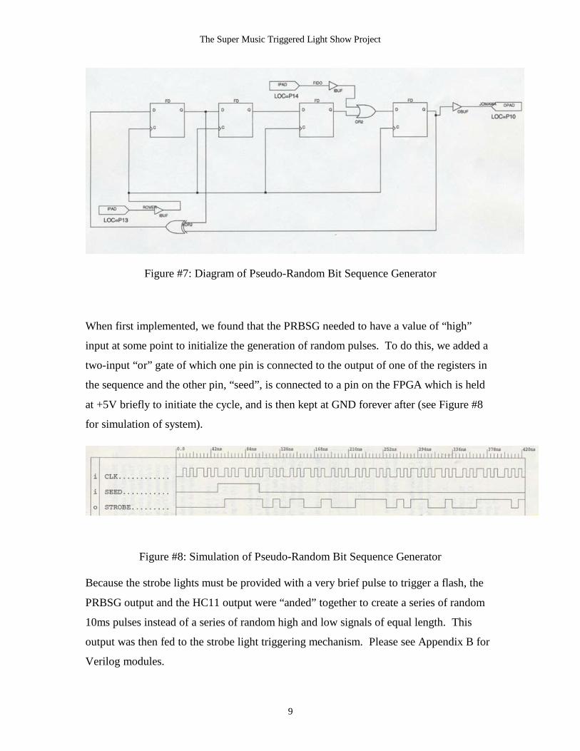
Figure #7: Diagram of Pseudo-Random Bit Sequence Generator
When first implemented, we found that the PRBSG needed to have a value of “high”
input at some point to initialize the generation of random pulses. To do this, we added a
two-input “or” gate of which one pin is connected to the output of one of the registers in
the sequence and the other pin, “seed”, is connected to a pin on the FPGA which is held
at +5V briefly to initiate the cycle, and is then kept at GND forever after (see Figure #8
for simulation of system).
Figure #8: Simulation of Pseudo-Random Bit Sequence Generator
Because the strobe lights must be provided with a very brief pulse to trigger a flash, the
PRBSG output and the HC11 output were “anded” together to create a series of random
10ms pulses instead of a series of random high and low signals of equal length. This
output was then fed to the strobe light triggering mechanism. Please see Appendix B for
Verilog modules.

The Super Music Triggered Light Show Project
10
ResultsThe HC11, FPGA, and strobe light combination was first tested against input
from a function generator in the form of sine, square, and triangle waves of varying
frequency with +2.5V DC offsets. The fastest dance music we found had a beat
frequency of 6.7Hz, and the slowest music had a beat frequency of around 1Hz. With
this range in mind, the system as it stands will detect a beat at each peak and output a
10ms pulse when at the maximum frequency of 6.7Hz sine wave, which is then converted
successfully into three different pseudo-random pulse signals for the three strobe lights.
Yet, when the beat is slowed down to 1Hz, the system detects several peaks during the
course of each actual peak because new data is always sampled 150ms after an initial
peak detection. Hence, with slow, rolling peaks in the form of a sine wave, the input data
is sampled several times while the signal is still rising, and is compared to the running
average yielding several 10ms pulses during the course of one peak. While this is taken
into consideration, we also found experimentally that the width of peaks indicative of
beat in music are usually 150ms wide or less. Hence, a musical input with a 1Hz beat
frequency should yield only one pulse per beat because the peaks in the music are
sufficiently narrow that the system should not sample and compare during the same peak
twice. To simulate this, a 1Hz square wave with a +3V DC offset and a small duty cycle
was created using a function generator, and the system behaved perfectly, creating one
pulse per wave.
After this testing, an analog musical input was fed into the system, scaled from
+1.5-4.5V with a +3V DC offset. The effect was not perfectly tuned. It was apparent
that the system could detect peaks indicative of beat, but that it was also detecting other
anomalous occurrences from time to time and creating anomalous strobe output.
For future work, the system could be tuned more completely. One method which
might help filter out anomalous output would be to adjust the HC11’s peak detection
algorithm to detect peaks that were higher than three times as high as the average input
value. Another useful route to pursue would be to provide a signal to the HC11 with a
steeper rise at the beginning of the peak, as originally simulated using Matlab. With
proper amplification and rise time from the input signal, the system as it stands may be
properly tuned to detect only peaks indicative of beat, filtering out other anomalies.

The Super Music Triggered Light Show Project
11
References
Many thanks to the helpful guys at Marvac Dow and the wonderful professors at Harvey
Mudd, specifically Prof. Baumgaertner, Prof. Rosenberg, Prof. Spjut, and of course, the
wonderful and magical Prof. Harris.
Parts List
Part Source Vendor Part # PriceStrobe Kit Parts Express K5300 $19.9512 volt relay Marvac Dow NTE R14-11D10-12 $10.525-6volt relay Marvac Dow NTE R56-7D $6.44LM741 Op Amp Stock Room LM741CM-NDLM318 Op Amp Stock Room LM318Transistor Micro P’s Lab H-2N-3904B

The Super Music Triggered Light Show Project
12
Parts Data
The 12-Volt Relay
NTE Type No.Nom.
VoltageContact
Arr.
CoilRes.
Ohms(Typ)
Nom.Power
Max.ContactCur. @28VDC
or120VAC
Diag.No
The 5-6-Volt Relay
Times
NTEType No.
Nom.Volt.VDC
ContactArr.
Typ.CoilRes.
Ohms
Max.PickupVDC
Min.DropOutVDC
Max.Curr.Amps
Max.Separate
Max.Release
Diag.No.
R14-11D10-12 12VDC DPDT 160 0.9W 10A D10
R56-7D.5-6 5 DPST-NO 200 3.8 0.5 0.50 700µs 75µs D27E

The Super Music Triggered Light Show Project
13
Appendix A: Assembly Code
*Elizabeth Johansen and Mike Lane*December 3, 2000*Final Project Assembly Code
***********************************Set pertinent variables
REGS EQU $1000 beginning of register stackADCTL EQU $30 address of A/D controlADR1 EQU $31 address of converted input dataOPTION EQU $39 used to power up A/D convertorPORTB EQU $1004 address of Port B, outputSAMP1 EQU $D001 addresses of four samples usedSAMP2 EQU $D002 to compute the running averageSAMP3 EQU $D003 of input dataSAMP4 EQU $D004AV EQU $D000 address of calculated average input
DCOFF EQU %10011010 value of +3V DC offset of inputADSET EQU %00100111 scan,1 channel only, PE7 inputADFIN EQU %10000000 A/D conversion finished mask
OUTHI EQU $01 output when beat is heardOUTLO EQU $00 output when beat is not heardPEAK1 EQU $D00A width of output peakPEAK2 EQU $D00B = PEAK1 X PEAK2TIME1 EQU $D006 wait time until check new data againTIME2 EQU $D007 = TIME1 X TIME2 X TIME3TIME3 EQU $D00CSAMPLE0 EQU $D008 sample period defined bySAMPLE1 EQU $D009 = SAMPLE0 X SAMPLE1**********************************
*Begin Routine
ORG $C100
LDX #REGS initialize register stackBSET $1039 %10000000 power up A/D converterLDAA #40 delay for >100 ms
DELAY DECA delay for A/D converterBNE DELAYLDAA #ADSET scan, look to PE7 for inputSTAA ADCTL,X
LDAA #OUTLO set initial output to lowSTAA PORTB
*Main Loop
The Super Music Triggered Light Show Project
14
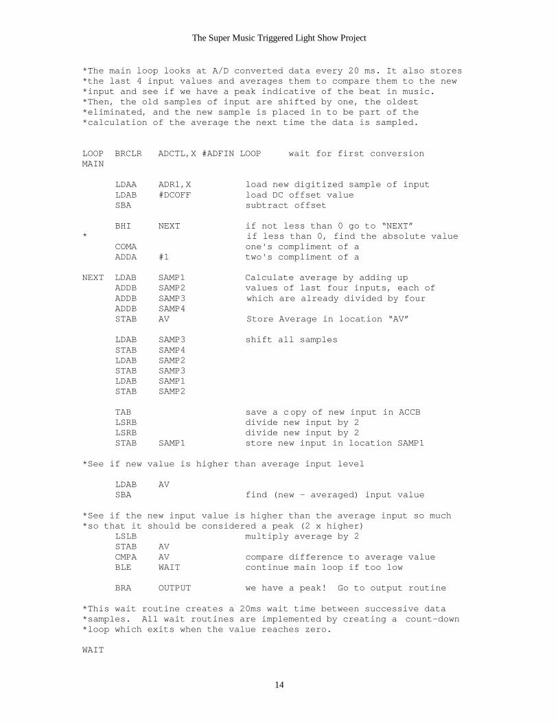
*The main loop looks at A/D converted data every 20 ms. It also stores*the last 4 input values and averages them to compare them to the new*input and see if we have a peak indicative of the beat in music.*Then, the old samples of input are shifted by one, the oldest*eliminated, and the new sample is placed in to be part of the*calculation of the average the next time the data is sampled.
LOOP BRCLR ADCTL,X #ADFIN LOOP wait for first conversionMAIN
LDAA ADR1,X load new digitized sample of inputLDAB #DCOFF load DC offset valueSBA subtract offset
BHI NEXT if not less than 0 go to “NEXT”* if less than 0, find the absolute value
COMA one's compliment of aADDA #1 two's compliment of a
NEXT LDAB SAMP1 Calculate average by adding upADDB SAMP2 values of last four inputs, each ofADDB SAMP3 which are already divided by fourADDB SAMP4STAB AV Store Average in location “AV”
LDAB SAMP3 shift all samplesSTAB SAMP4LDAB SAMP2STAB SAMP3LDAB SAMP1STAB SAMP2
TAB save a copy of new input in ACCBLSRB divide new input by 2LSRB divide new input by 2STAB SAMP1 store new input in location SAMP1
*See if new value is higher than average input level
LDAB AVSBA find (new - averaged) input value
*See if the new input value is higher than the average input so much*so that it should be considered a peak (2 x higher)
LSLB multiply average by 2STAB AVCMPA AV compare difference to average valueBLE WAIT continue main loop if too low
BRA OUTPUT we have a peak! Go to output routine
*This wait routine creates a 20ms wait time between successive data*samples. All wait routines are implemented by creating a count-down*loop which exits when the value reaches zero.
WAIT

The Super Music Triggered Light Show Project
15
LDAA SAMPLE0 WAIT0 DECA wait of length SAMPLE1 x SAMPLE0
LDAB SAMPLE1WAIT1 DECB
NOP filler to make the wait long enoughNOPNOPNOPNOPNOPNOPNOPNOPNOPNOPNOPNOPNOPNOPNOPNOPNOPNOPNOPNOPNOPNOPNOPCMPB #$00BNE WAIT1
CMPA #$00BNE WAIT0
JMP MAIN go back to main loop when done waiting
*Output Routine to follow in the case of a peak
OUTPUT LDAA #OUTHI set output to hiSTAA PORTB
LDAA PEAK1 wait 10ms, specified by PEAK1 X PEAK2WAIT2 DECA
LDAB PEAK2WAIT5 DECB
NOPNOPNOPNOPNOP

The Super Music Triggered Light Show Project
16
NOPCMPB #$00BNE WAIT5
CMPA #$00BNE WAIT2
LDAA #OUTLO set output back to loSTAA PORTB
LDS $D100 initialize stack pointer
LDAB TIME1 wait 140ms, TIME1 X TIME2 X TIME3WAIT3 DECB
LDAA TIME2WAIT4 DECA
PSHA push value of ACCA onto stackLDAA TIME3
WAIT6 DECAPSHA push value of ACCA onto stackPSHB push value of ACCB onto stack
* while waiting, continually update the* running average by sampling new data
LDAA ADR1,X load new digitized sample of inputLDAB #DCOFF load DC offset valueSBA subtract offset
BHI NEXT2 if not less than 0 go to next step* if less than 0, get absolute value
COMA one's compliment of aADDA #1 two's compliment of a
NEXT2
LDAB SAMP3 shift all samplesSTAB SAMP4LDAB SAMP2STAB SAMP3LDAB SAMP1STAB SAMP2
LSRA divide new input by 2LSRA divide new input by 2STAA SAMP1 store new input in location SAMP1
PULB pull value of ACCB off of stackPULA pull value of ACCA off of stackCMPA #$00 BNE WAIT6
PULA pull value of ACCA off of stackCMPA #$00BNE WAIT4

The Super Music Triggered Light Show Project
17
CMPB #$00BNE WAIT3
JMP MAIN return to main loop

The Super Music Triggered Light Show Project
18
Appendix B: Verilog Code
//The first three modules (pseudorandom1-3) generate the pseudorandom pulses.//The “seed”, which starts the system up, is connected to a different wire in each//generator in order to create three different pseudo-random bit sequences for the three//separate strobes.
module pseudorandom1 (signal, seed, strobe) ;
input signal, seed;output strobe;
reg q1, q2, q3, q4, q5; //These describe the wires between thereg q1next, q2next, q3next, q4next, q5next; //registers of the shift register
always @(posedge signal) //Implements a shift registerbegin
q5 <= q5next;q4 <= q4next;q3 <= q3next;q2 <= q2next;q1 <= q1next;q5next <= q4;q4next <= q3;q3next <= q2;q2next <= q1|seed; //Here is the seed inputq1next <= q2^q5;
end
assign strobe = q5; //The wire q5 is also the output wire
endmodule
module pseudorandom2 (signal, seed, strobe) ;
input signal, seed;output strobe;
reg q1, q2, q3, q4, q5; //These describe the wires between thereg q1next, q2next, q3next, q4next, q5next; //registers of the shift register
always @(posedge signal) //Implements a shift registerbegin
q5 <= q5next;q4 <= q4next;

The Super Music Triggered Light Show Project
19
q3 <= q3next;q2 <= q2next;q1 <= q1next;q5next <= q4;q4next <= q3;q3next <= q2|seed; //Here is the seed inputq2next <= q1;q1next <= q2^q5;
end
assign strobe = q5; //The wire q5 is also the output wire
endmodule
module pseudorandom3 (signal, seed, strobe) ;
input signal, seed;output strobe;
reg q1, q2, q3, q4, q5; //These describe the wires between thereg q1next, q2next, q3next, q4next, q5next; //registers of the shift register
always @(posedge signal) //Implements a shift registerbegin
q5 <= q5next;q4 <= q4next;q3 <= q3next;q2 <= q2next;q1 <= q1next;q5next <= q4;q4next <= q3|seed; //Here is the seed inputq3next <= q2;q2next <= q1;q1next <= q2^q5;
end
assign strobe = q5; //The wire q5 is the output
endmodule
//This module takes in the pulsed signal from the HC11 and “ands” it with the signal//coming out of the pseudo-random generator to create a pulsed, random output.
module pulsegen (random, signal, strobe) ;

The Super Music Triggered Light Show Project
20
input random, signal;output strobe;
assign strobe = signal & random;
endmodule
//This module takes in the HC11 signal and the seed to start the pseudo random generator//and uses the pseudorandom and pulsegen modules to create a psedo-random pulse//signal.
module toplevel (signal, seed, strobe1, strobe2, strobe3) ;
input signal, seed; //Input HC11 signal and seed.output strobe1, strobe2, strobe3; //Outputs to the three strobes.
pseudorandom1 ran1(signal, seed, random1);//Call the PRBSG three timespseudorandom2 ran2(signal, seed, random2);//to generate three differentpseudorandom3 ran3(signal, seed, random3);//random sequences.
pulsegen gen1(random1, signal, strobe1); //Convert the PRBSG outputpulsegen gen2(random2, signal, strobe2); //into a series of randompulsegen gen3(random3, signal, strobe3); //pulses.
endmodule