the steel–concrete interface - springer · pdf filekefei li, alexander michel, shishir...
TRANSCRIPT

ORIGINAL ARTICLE
The steel–concrete interface
Ueli M. Angst . Mette R. Geiker . Alexander Michel . Christoph Gehlen .
Hong Wong . O. Burkan Isgor . Bernhard Elsener . Carolyn M. Hansson .
Raoul Francois . Karla Hornbostel . Rob Polder . Maria Cruz Alonso .
Mercedes Sanchez . Maria Joao Correia . Maria Criado .
A. Sagues . Nick Buenfeld
Received: 8 December 2016 / Accepted: 31 January 2017 / Published online: 27 February 2017
� The Author(s) 2017. This article is published with open access at Springerlink.com
Abstract Although the steel–concrete interface
(SCI) is widely recognized to influence the durability
of reinforced concrete, a systematic overview and
detailed documentation of the various aspects of the
SCI are lacking. In this paper, we compiled a
comprehensive list of possible local characteristics at
the SCI and reviewed available information regarding
their properties as well as their occurrence in engi-
neering structures and in the laboratory. Given the
complexity of the SCI, we suggested a systematic
approach to describe it in terms of local characteristics
and their physical and chemical properties. It was
found that the SCI exhibits significant spatial
inhomogeneity along and around as well as perpen-
dicular to the reinforcing steel. The SCI can differ
strongly between different engineering structures and
also between different members within a structure;
particular differences are expected between structures
built before and after the 1970/1980s. A single SCI
representing all on-site conditions does not exist.
Additionally, SCIs in common laboratory-made spec-
imens exhibit significant differences compared to
engineering structures. Thus, results from laboratory
studies and from practical experience should be
applied to engineering structures with caution. Finally,
recommendations for further research are made.
This report was prepared by the working group within RILEM
TC 262-SCI, and further reviewed and approved by all
members of the RILEM TC 262-SCI.
TC Chairman: Ueli Angst.
TC Secretary: Mette Geiker.
TC Members: Johan Ahlstrom, Mark G. Alexander, Ueli Angst,
Luca Bertolini, Nick Buenfeld, Christian Christodoulou, Maria
joao Correia, Maria Criado, Maria Cruz Alonso, Bernhard
Elsener, Raoul Francois, Christoph Gehlen, Mette Geiker, Peter
Grassl, Joost Gulikers, Carolyn Hansson, Karla Hornbostel, O.
Burkan Isgor, Marc Kosalla, Claus K. Larsen, Andraz Legat,
Kefei Li, Alexander Michel, Shishir Mundra, Mike B. Otieno,
Jose Pacheco Farias, Radhakrishna G. Pillai, Rob Polder,
Michael Raupach, Mercedes Sanchez Moreno, Alberto Sagues,
Henrik Erndahl Sørensen, Luping Tang, Elsa Vaz Pereira,
Talakokula Visalakshi, Hong S. Wong, Linwen Yu.
U. M. Angst (&) � B. Elsener
Institute for Building Materials (IfB), ETH Zurich,
Stefano-Franscini-Platz 3, 8093 Zurich, Switzerland
e-mail: [email protected]
M. R. Geiker � K. Hornbostel
Department of Structural Engineering, Norwegian
University of Science and Technology (NTNU),
7491 Trondheim, Norway
M. R. Geiker � A. Michel
Department of Civil Engineering, Technical University of
Denmark (DTU), 2800 Kgs. Lyngby, Denmark
C. Gehlen
Centre for Building Materials (cbm), Technical University
Munich, Baumbachstr. 7, 81245 Munich, Germany
Materials and Structures (2017) 50:143
DOI 10.1617/s11527-017-1010-1

Keywords Steel–concrete interface � Interfacial
transition zone � Durability � Corrosion �Inhomogeneity � Variability
1 Introduction
The steel–concrete interface (SCI) influences the
structural behavior and durability performance of
reinforced concrete, and thus, plays an important role
in engineering of reinforced concrete structures. The
SCI has a particular influence on the corrosion
behavior in chloride exposure environments and in
the case of carbonation. It also influences certain
aspects of the bond between steel and concrete such as
adhesion between steel and concrete, which is partic-
ularly important in the case of smooth reinforcing steel
where mechanical interlocking does not exist.
Some of the large uncertainties in durability
engineering—particularly in explaining and forecast-
ing initiation of chloride-induced corrosion—can be
traced to insufficient understanding of the influence of
local characteristics of the SCI [1, 2]. To name a few
prominent examples, pores, voids, and cracks have
been observed to strongly influence initiation of
chloride-induced corrosion under some conditions
[3–10], but seem to have no influence under other
conditions [9, 11]. There are many other characteris-
tics at the SCI that may, or may not, occur locally and
that may potentially influence the local susceptibility
of the reinforcement to corrosion initiation. A sys-
tematic overview and detailed documentation of these,
however, are lacking.
This contribution summarizes the state-of-the-art
concerning the occurrence—both on-site and in lab-
oratory experiments—of different local characteristics
at the SCI, and describes their physical and chemical
properties. The influence of these local characteristics
on corrosion initiation will be addressed in a separate
publication.
The present paper was prepared by members of
RILEM TC 262-SCI and is to a large extent based
on the presentations and discussions during the first
five TC meetings. This paper focuses on conven-
tional carbon steel reinforcement in Portland cement
based concrete, leaving considerations of coated,
alloyed or high-strength steels as well as other
binder types for future treatment. Additionally, the
influences of repair techniques (electrochemical
remediation, e.g. cathodic prevention and protection)
and of corrosion inhibitors and other chemical
admixtures on the SCI are excluded in this work.
This paper describes the SCI in the hardened
H. Wong � N. Buenfeld
Concrete Durability Group, Department of Civil and
Environmental Engineering, Imperial College London,
London SW7 2AZ, UK
O. B. Isgor
School of Civil and Construction Engineering, Oregon
State University, Corvallis, OR, USA
C. M. Hansson
Department of Mechanical and Mechatronics
Engineering, University of Waterloo, Waterloo,
ON N2L 3G1, Canada
R. Francois
LMDC, INSA, UPS, Universite de Toulouse, Toulouse,
France
R. Polder
TNO Technical Sciences/Structural Reliability, Delft, The
Netherlands
R. Polder
Delft University of Technology, Civil Engineering/
Materials and Environment, Delft, The Netherlands
M. C. Alonso � M. Sanchez
Institute of Construction Science Eduardo Torroja-CSIC,
Serrano Galvache 4, 28033 Madrid, Spain
M. J. Correia
Materials Department, National Laboratory for Civil
Engineering (LNEC), Av. Do Brasil, 101,
1700-066 Lisbon, Portugal
M. Criado
Department of Materials Science and Engineering, The
University of Sheffield, Sir Robert Hadfield Building,
Sheffield S1 3JD, UK
A. Sagues
Department of Civil and Environmental Engineering,
University of South Florida, 4202 E. Fowler Avenue,
Tampa, FL 33620-5350, USA
143 Page 2 of 24 Materials and Structures (2017) 50:143

concrete after initial cement hydration and steel
passivation, but before corrosion has initiated, i.e. it
considers the SCI of passive steel during the so-
called initiation stage (Fig. 1). The time scale of this
stage often forms a substantial part of the service
life of engineering structures.
2 Documented characteristics at the SCI
2.1 Terminology and conceptual description
of the SCI
Table 1 lists features that are known to occur at the
SCI both in laboratory specimens and in engineering
structures. We suggest ‘‘local characteristics’’ as a
general term to embrace all the individual features and
their local properties. Note that the term ‘‘local
characteristics’’ may refer to both local differences
with increasing distance from the steel surface (per-
pendicular to steel surface) and to local differences
across the steel surface, both along the reinforcing
steel bar and along its circumference.
Figure 2 shows some selected characteristics of the
SCI; for reasons of clarity it is not possible to display
all features listed in Table 1. We found it useful to
divide the local characteristics into those inherent to
the reinforcing steel bar (steel part of the SCI) and
those in the concrete adjacent to the steel (concrete
part of the SCI). This classification, however, does not
mean that we consider these parts independent of each
other. There are obvious interactions when reinforcing
steel bars are embedded in concrete as will be
discussed in Sect. 3.2. In terms of length scales, we
divide the local characteristics into macroscopic and
microscopic features. In agreement with various
dictionaries, we define ‘‘macroscopic’’ as something
‘‘observable by the naked eye’’. The resolution of the
human eye in close reading distance is of the order of
50–100 micrometers [12]. Thus, ‘‘microscopic’’ refers
to dimensions smaller than this.
2.2 Reinforcing steel
From the beginning of construction with reinforced
concrete in the late nineteenth century, a wide variety of
reinforcing steels has been used. Metallurgy and rebar
geometry have changed substantially over time due to
the increased requirements for mechanical properties
and historical evolution of manufacturing processes
[13]. Today, across Europe, approx. 200 different steel
grades exist, which vary in terms of yield and tensile
strength (Re and Rm), elongation at ultimate strength
(Agt) and hardening ratio (Rm/Re). According to the
characteristic yield strength—that varies between
370 MPa and 600 MPa within Europe—reinforcing
steel is classified into strength grades, where for
example the value 500 in the class B500 represents
the characteristic yield strength of the rebar of 500 MPa
[14]. Reinforcing steel is also classified according to its
elongation at ultimate strength and depending on the
hardening ratio, where three different ductility classes
for steel reinforcing bars are defined. The classes ‘‘A’’,
‘‘B’’ and ‘‘C’’ belong to Agt higher than 2.5, 5.0 and
7.5% and by hardening ratios higher than 1.05, 1.08 and
between 1.15 and 1.35, respectively.
Different methods can be used to satisfy the
strength and ductility requirements for construction
age of structure
degr
ee o
f det
erio
ratio
n
corrosiononsetinitiation stage propagation stage
0
stabilizationstagefor SCI
focus ofthis publication
Fig. 1 Schematic
illustration showing the
stage in the service life of a
reinforced concrete
structure during which the
steel–concrete interface
(SCI) is considered in this
work
Materials and Structures (2017) 50:143 Page 3 of 24 143
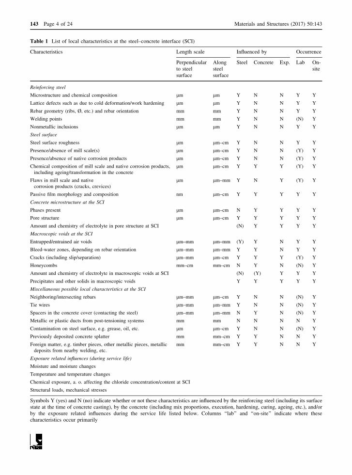
Table 1 List of local characteristics at the steel–concrete interface (SCI)
Characteristics Length scale Influenced by Occurrence
Perpendicular
to steel
surface
Along
steel
surface
Steel Concrete Exp. Lab On-
site
Reinforcing steel
Microstructure and chemical composition lm lm Y N N Y Y
Lattice defects such as due to cold deformation/work hardening lm lm Y N N Y Y
Rebar geometry (ribs, Ø, etc.) and rebar orientation mm mm Y N N Y Y
Welding points mm mm Y N N (N) Y
Nonmetallic inclusions lm lm Y N N Y Y
Steel surface
Steel surface roughness lm lm–cm Y N N Y Y
Presence/absence of mill scale(s) lm lm–cm Y N N (Y) Y
Presence/absence of native corrosion products lm lm–cm Y N N (Y) Y
Chemical composition of mill scale and native corrosion products,
including ageing/transformation in the concrete
lm lm–cm Y Y Y (Y) Y
Flaws in mill scale and native
corrosion products (cracks, crevices)
lm lm–mm Y N Y (Y) Y
Passive film morphology and composition nm lm–cm Y Y Y Y Y
Concrete microstructure at the SCI
Phases present lm lm–cm N Y Y Y Y
Pore structure lm lm–cm Y Y Y Y Y
Amount and chemistry of electrolyte in pore structure at SCI (N) Y Y Y Y
Macroscopic voids at the SCI
Entrapped/entrained air voids lm–mm lm–mm (Y) Y N Y Y
Bleed-water zones, depending on rebar orientation lm–mm lm–mm Y Y N Y Y
Cracks (including slip/separation) lm–mm lm–cm Y Y Y (Y) Y
Honeycombs mm–cm mm–cm N Y N (N) Y
Amount and chemistry of electrolyte in macroscopic voids at SCI (N) (Y) Y Y Y
Precipitates and other solids in macroscopic voids Y Y Y Y Y
Miscellaneous possible local characteristics at the SCI
Neighboring/intersecting rebars lm–mm lm–cm Y N N (N) Y
Tie wires lm–mm lm–mm Y N N (N) Y
Spacers in the concrete cover (contacting the steel) lm–mm lm–mm N Y N (N) Y
Metallic or plastic ducts from post-tensioning systems mm mm N N N N Y
Contamination on steel surface, e.g. grease, oil, etc. lm lm–cm Y N N (N) Y
Previously deposited concrete splatter mm mm–cm Y Y N N Y
Foreign matter, e.g. timber pieces, other metallic pieces, metallic
deposits from nearby welding, etc.
mm mm–cm Y Y N N Y
Exposure related influences (during service life)
Moisture and moisture changes
Temperature and temperature changes
Chemical exposure, a. o. affecting the chloride concentration/content at SCI
Structural loads, mechanical stresses
Symbols Y (yes) and N (no) indicate whether or not these characteristics are influenced by the reinforcing steel (including its surface
state at the time of concrete casting), by the concrete (including mix proportions, execution, hardening, curing, ageing, etc.), and/or
by the exposure related influences during the service life listed below. Columns ‘‘lab’’ and ‘‘on-site’’ indicate where these
characteristics occur primarily
143 Page 4 of 24 Materials and Structures (2017) 50:143

standards, and these have led to differences in steel
microstructure [15–17]. Established processes are
micro-alloying (MA), cold working (CW), stretching
(STR), and thermomechanical strengthening, e.g. the
TempCore� process (TEMP). In thermomechanical
strengthening, the steel is immediately and rapidly
quenched on the surface by spraying water after the
last hot rolling sequence. Following this treatment, the
steel is exposed to air cooling. Within this period the
martensitic quenched layer is tempered by the pre-
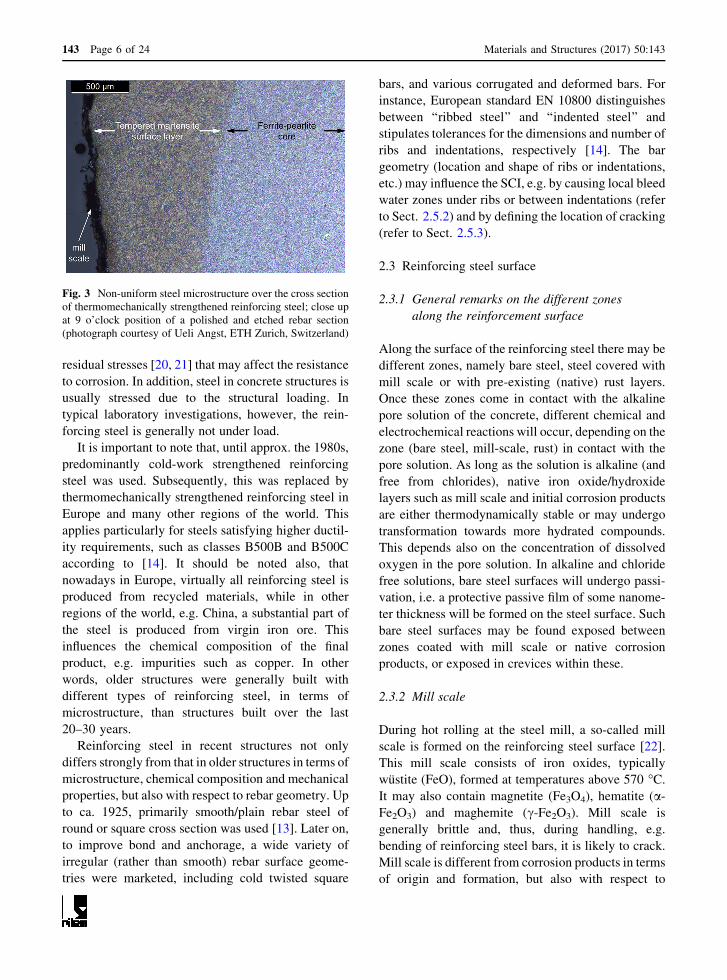
served heat from the core. Thermomechanical
strengthening thus leads to a composite microstructure
(Fig. 3) with a tempered martensite surface layer and a
more ductile ferrite/pearlite core [15–18]. The classic
hot-rolled and cold-worked, as well as micro-alloyed,
reinforcing steel bars, on the other hand, have a
relatively uniform microstructure across the cross
section. Work-hardening by means of cold deforming
typically starts from the ferrite-pearlite type of
microstructures, which are maintained during the
process. Microalloyed steels often consist of a ferritic
base matrix. All these microstructures will differ in
terms of grain size, nonmetallic inclusions and impu-
rities, which may affect the susceptibility to corrosion
[19]. Additionally, the composite microstructure of
thermomechanically strengthened rebars also exhibit
Fig. 2 Schematic
illustration of selected
characteristics at the steel–
concrete interface (SCI) that
may or may not be present
locally. Red dashed lines
indicate preferential
pathways for chloride
ingress; blue dots represent
adsorbed water (only shown
for large pores). Water in
cement paste not shown.
(Color figure online)
Materials and Structures (2017) 50:143 Page 5 of 24 143
residual stresses [20, 21] that may affect the resistance
to corrosion. In addition, steel in concrete structures is
usually stressed due to the structural loading. In
typical laboratory investigations, however, the rein-
forcing steel is generally not under load.
It is important to note that, until approx. the 1980s,
predominantly cold-work strengthened reinforcing
steel was used. Subsequently, this was replaced by
thermomechanically strengthened reinforcing steel in
Europe and many other regions of the world. This
applies particularly for steels satisfying higher ductil-
ity requirements, such as classes B500B and B500C
according to [14]. It should be noted also, that
nowadays in Europe, virtually all reinforcing steel is
produced from recycled materials, while in other
regions of the world, e.g. China, a substantial part of
the steel is produced from virgin iron ore. This
influences the chemical composition of the final
product, e.g. impurities such as copper. In other
words, older structures were generally built with
different types of reinforcing steel, in terms of
microstructure, than structures built over the last
20–30 years.
Reinforcing steel in recent structures not only
differs strongly from that in older structures in terms of
microstructure, chemical composition and mechanical
properties, but also with respect to rebar geometry. Up
to ca. 1925, primarily smooth/plain rebar steel of
round or square cross section was used [13]. Later on,
to improve bond and anchorage, a wide variety of
irregular (rather than smooth) rebar surface geome-
tries were marketed, including cold twisted square
bars, and various corrugated and deformed bars. For
instance, European standard EN 10800 distinguishes
between ‘‘ribbed steel’’ and ‘‘indented steel’’ and
stipulates tolerances for the dimensions and number of
ribs and indentations, respectively [14]. The bar
geometry (location and shape of ribs or indentations,
etc.) may influence the SCI, e.g. by causing local bleed
water zones under ribs or between indentations (refer
to Sect. 2.5.2) and by defining the location of cracking
(refer to Sect. 2.5.3).
2.3 Reinforcing steel surface
2.3.1 General remarks on the different zones
along the reinforcement surface
Along the surface of the reinforcing steel there may be
different zones, namely bare steel, steel covered with
mill scale or with pre-existing (native) rust layers.
Once these zones come in contact with the alkaline
pore solution of the concrete, different chemical and
electrochemical reactions will occur, depending on the
zone (bare steel, mill-scale, rust) in contact with the
pore solution. As long as the solution is alkaline (and
free from chlorides), native iron oxide/hydroxide
layers such as mill scale and initial corrosion products
are either thermodynamically stable or may undergo
transformation towards more hydrated compounds.
This depends also on the concentration of dissolved
oxygen in the pore solution. In alkaline and chloride
free solutions, bare steel surfaces will undergo passi-
vation, i.e. a protective passive film of some nanome-
ter thickness will be formed on the steel surface. Such
bare steel surfaces may be found exposed between
zones coated with mill scale or native corrosion
products, or exposed in crevices within these.
2.3.2 Mill scale
During hot rolling at the steel mill, a so-called mill
scale is formed on the reinforcing steel surface [22].
This mill scale consists of iron oxides, typically
wustite (FeO), formed at temperatures above 570 �C.
It may also contain magnetite (Fe3O4), hematite (a-
Fe2O3) and maghemite (c-Fe2O3). Mill scale is
generally brittle and, thus, during handling, e.g.
bending of reinforcing steel bars, it is likely to crack.
Mill scale is different from corrosion products in terms
of origin and formation, but also with respect to
Fig. 3 Non-uniform steel microstructure over the cross section
of thermomechanically strengthened reinforcing steel; close up
at 9 o’clock position of a polished and etched rebar section
(photograph courtesy of Ueli Angst, ETH Zurich, Switzerland)
143 Page 6 of 24 Materials and Structures (2017) 50:143
morphology and composition. It is noted that certain
rebar treatments (e.g. the Thermex� process) involve a
final jetted water quenching step, which may effec-
tively eliminate much of the high temperature scale,
leaving only a thin deposit formed at lower temper-
atures. For cold-work hardened steel, the major part of
mill scales will be eliminated during processing.
Ghods et al. [23] investigated the properties of the
mill scale on different reinforcing steel bars by means
of scanning electron microscopy (SEM) and focused
ion beam microscopy. Cross-sectional images showed
that the mill scale exhibited a crystalline structure and
was deposited on the steel substrate in the form of
columnar grains. While on the reinforcing steel from
one manufacturer only certain areas of the steel were
covered with a relatively thin layer of mill scale
(maximum thickness of 2 lm), the steel from other
manufacturers was more uniformly coated with mill
scale (thickness up to 30–40 lm). Because of their
larger thickness, the mill scale and the interface
between steel and mill scale exhibited voids, crevices
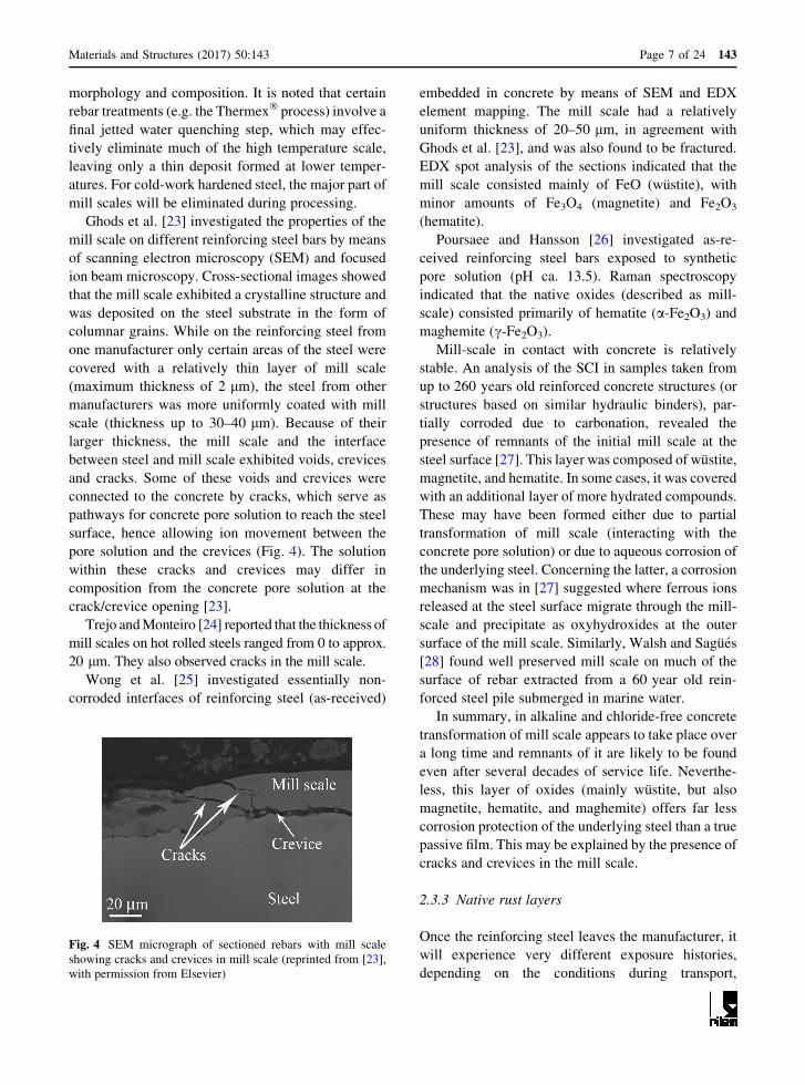
and cracks. Some of these voids and crevices were
connected to the concrete by cracks, which serve as
pathways for concrete pore solution to reach the steel
surface, hence allowing ion movement between the
pore solution and the crevices (Fig. 4). The solution
within these cracks and crevices may differ in
composition from the concrete pore solution at the
crack/crevice opening [23].
Trejo and Monteiro [24] reported that the thickness of
mill scales on hot rolled steels ranged from 0 to approx.
20 lm. They also observed cracks in the mill scale.
Wong et al. [25] investigated essentially non-
corroded interfaces of reinforcing steel (as-received)
embedded in concrete by means of SEM and EDX
element mapping. The mill scale had a relatively
uniform thickness of 20–50 lm, in agreement with
Ghods et al. [23], and was also found to be fractured.
EDX spot analysis of the sections indicated that the
mill scale consisted mainly of FeO (wustite), with
minor amounts of Fe3O4 (magnetite) and Fe2O3
(hematite).
Poursaee and Hansson [26] investigated as-re-
ceived reinforcing steel bars exposed to synthetic
pore solution (pH ca. 13.5). Raman spectroscopy
indicated that the native oxides (described as mill-
scale) consisted primarily of hematite (a-Fe2O3) and
maghemite (c-Fe2O3).
Mill-scale in contact with concrete is relatively
stable. An analysis of the SCI in samples taken from
up to 260 years old reinforced concrete structures (or
structures based on similar hydraulic binders), par-
tially corroded due to carbonation, revealed the
presence of remnants of the initial mill scale at the
steel surface [27]. This layer was composed of wustite,
magnetite, and hematite. In some cases, it was covered
with an additional layer of more hydrated compounds.
These may have been formed either due to partial
transformation of mill scale (interacting with the
concrete pore solution) or due to aqueous corrosion of
the underlying steel. Concerning the latter, a corrosion
mechanism was in [27] suggested where ferrous ions
released at the steel surface migrate through the mill-
scale and precipitate as oxyhydroxides at the outer
surface of the mill scale. Similarly, Walsh and Sagues
[28] found well preserved mill scale on much of the
surface of rebar extracted from a 60 year old rein-
forced steel pile submerged in marine water.
In summary, in alkaline and chloride-free concrete
transformation of mill scale appears to take place over
a long time and remnants of it are likely to be found
even after several decades of service life. Neverthe-
less, this layer of oxides (mainly wustite, but also
magnetite, hematite, and maghemite) offers far less
corrosion protection of the underlying steel than a true
passive film. This may be explained by the presence of
cracks and crevices in the mill scale.
2.3.3 Native rust layers
Once the reinforcing steel leaves the manufacturer, it
will experience very different exposure histories,
depending on the conditions during transport,
Fig. 4 SEM micrograph of sectioned rebars with mill scale
showing cracks and crevices in mill scale (reprinted from [23],
with permission from Elsevier)
Materials and Structures (2017) 50:143 Page 7 of 24 143

handling, and storage. Particularly indoor or sheltered
vs. outdoor storage conditions strongly affect the
formation of superficial rust layers. Corrosion prod-
ucts may form under atmospheric corrosion condi-
tions, in an adsorbed layer of moisture, or in larger
liquid volumes present on the steel surface such as
water droplets (rebars exposed to rain, condensation of
water) or in cases of (partial) immersion in liquid
water. Furthermore, exposure to salt-spray and salt
containing aerosols (e.g. when stored on construction
sites exposed to marine environment) may give rise to
chloride-containing rust layers. These rust layers will
likely differ in composition and morphology depend-
ing on the exposure conditions and will, most likely,
consist of hydroxide layers rather than oxides. More-
over, in contrast to mill scale, the rust layers formed
after the steel manufacturing process will not contain
significant amounts of wustite.
Within the work carried out in RILEM TC
235-CTC, rebars were collected from laboratories in
9 different countries, primarily from Europe, in so-
called ‘‘as-received’’ condition and tested. These
surfaces differed significantly in terms of visual
appearance. Furthermore, significant differences in
the electrochemical behaviour of these surfaces were
observed, depending on the amount of red/brown rust
present [19].
Stefanoni et al. [29] measured local open circuit
potentials of individual points on the surface of ‘‘as-
received’’ reinforcement steels by locally contacting
the steel with a test electrolyte and an electrochem-
ical sensor. Surfaces with only black mill-scale or
rebars that were severely pre-rusted (entire surface
covered with rust) showed a narrow distribution of
local open circuit potentials (standard deviation ca.
40 mV) whereas the intermediate situation includ-
ing both zones of almost bare steel and zones
coated with red-brown corrosion products, spanned
a large range in terms of local electrochemical
properties. While the local open circuit potentials of
pre-rusted rebars spanned a range of ca. 200 mV,
immersion in an alkaline solution reduced this
inhomogeneity to ca. 20 mV within one day
(measured after removal from solution) [29]. This
indicates relatively fast transformation, i.e. towards
more anodic potentials, of the rust and mill-scale
initially present on the steel surface when in contact
with alkaline electrolyte such as concrete pore
solution.
2.3.4 Passive film
Formation of passive films The formation of a passive
film in alkaline environments of different pH has been
mainly studied in solutions by electrochemical tech-
niques. The steel surface was machined [30], ground
[31], sandblasted [26, 32] or in most cases mechan-
ically polished [33–37]. Upon exposure to alkaline
solutions, literature work agrees on an asymptotical
increase of the open circuit potential (OCP)
[26, 30–34, 36–40] and of the polarization resistance
[32, 37, 38, 40] with time of exposure, indicating the
formation of a protective iron oxide film. Although a
protective passive film starts to form soon after
exposure of steel to passivating solutions, the quality
and stability of the film depends on the exposure
duration and the chemical composition of the passi-
vating solution. Longer immersion times lead to
higher polarization resistance [30, 37, 40]. While at
pH[ 13, protective properties of the passive film are
clearly observed after about 1d of immersion, at least
3–5 days are required for steel in saturated Ca(OH)2
(pH * 12.5) [26, 38, 40–42]. However, even for
prolonged immersion, saturated Ca(OH)2 solutions
may not be representative for concrete pore solutions
[40]. Sulfate ions have been shown to have a negative
influence on film quality [41].
Structure of passive films Surface analysis has
shown that the passive film formed on steel in alkaline
solutions has a bi-layer structure [37, 43, 44] with an
inner Fe2?-rich oxy-hydroxide (1–3 nm) and an outer
Fe3?-rich hydroxide film (5–10 nm), with the overall
thickness typically in the range of 3–15 nm
[34, 36, 44]. With increasing time of immersion, the
outer Fe3? layer of the film increases in thickness,
while the inner Fe2? layer remains relatively stable,
leading to an observation of increasing ratio Fe3?/
Fe2? in the oxide film [34, 37, 38]. This change in
Fe3?/Fe2? in the overall passive film has been found to
be potential dependent [34, 37, 43] and can lead to a
pseudo-capacity when subjected to DC currents or at
very low frequencies of AC signals [45]. The higher
Fe3? content of the bulk film corresponds to more
positive OCP or higher polarization resistances
[34, 37]. At typical potentials of passive steel in
alkaline, oxygenated concrete, the passive film can be
expected to consist mainly of Fe3? oxide and Fe3?
oxy-hydroxide [43]. Based on Raman spectroscopy it
was in [26, 40] concluded that the passive film
143 Page 8 of 24 Materials and Structures (2017) 50:143

composition is similar in concrete pore solutions and
in sat. Ca(OH)2. However, Ghods et al. [46] reported
the presence of Ca, K, and Na in the passive film from
the passivating solutions, suggesting that the pore
solution composition may have an influence on the
passive film composition and properties.
Protective properties Formation of the passive film
leads to a decrease in corrosion rate with time reaching
values of\0.1 lA/cm2 (1 mA/m2) corresponding to
mass loss\1 lm/year, i.e. an insignificant rate
[32, 37, 38, 40]. This protective nature of the passive
state is associated to a marked decrease in the ionic
conduction in the film (ion barrier); a lower electronic
conduction was also reported [39]. The passive state is
maintained in reinforced concrete structures for a very
long time, but may be lost when chloride ions reach the
steel. Chloride-induced depassivation has been asso-
ciated with a change of the oxidation state of the inner
part of the passive film [26, 44, 47] leading to
breakdown of the film. As a consequence, experiments
that probe the resistance against chloride-induced
corrosion should start only after a sufficiently long
pre-passivation time that varies according to the pH of
the electrolyte [26, 38, 40, 41] (see above). As the
onset of chloride-induced corrosion is a local phe-
nomenon it is not yet established if a higher surface-
averaged polarization resistance always corresponds
to a higher resistance against pitting corrosion.
Influence of structural loads Experimental investi-
gations have shown that passive films formed on steel
specimens degrade when subjected to mechanical
stresses. Feng et al. [48] performed electrochemical
impedance spectroscopy on steel samples while they
were immersed in alkaline solutions and simultane-
ously subjected to mechanical stresses. The polarisa-
tion resistance was found to significantly decrease
with increasing applied stress. This was explained by
cracking and delamination/spalling of the relatively
brittle passive film. The results also indicated that
passive films are more seriously damaged under
compressive stresses than under tensile stresses. The
hypothesis is that the passive film buckles and
becomes detached over a larger area than when only
cracks are formed in the case of tensile stresses. In
another study [49] steel samples were first passivated
in alkaline solution (pH 12.74) and then exposed to air
and subjected to bending leading to tensile stresses in
the passive film. This simulates the situation of a
reinforced concrete structure under alternating drying/
wetting conditions. After loading, the specimens were
immersed back in the alkaline solution and repassiva-
tion times were measured (in unloaded state). It was
found that the steel needed longer times to repassivate
when previously subjected to higher mechanical
stresses.
2.3.5 Steel surface area and surface roughness
There has been significant research on the corrosion
behaviour of metallographically polished surfaces of
steel [50–52]. While this is an ideal study of the basic
alloy properties, it does not represent the corrosion
behaviour of ribbed/indented, as-received reinforcing
bars in practice (cf. Sects. 2.3.2 and 2.3.3). Similarly,
in recognition of the blurring effects of pre-existing
rust layers or mill scale on the results of corrosion tests
with reinforcing steels, these oxide/hydroxide layers
have also frequently been removed by abrasive
blasting (such as sandblasting) [32]. The steel surface
thus exposed may appear to be rougher than that of the
initial mill scale, at least at some magnification levels,
but the blasted steel surface can actually show less
ability to sustain cathodic reactions than the mill scale
[53]. For steel already scale-free, increasingly finer
surface finishes do decrease the amount of effective,
exposed steel surface area [54, 55]. Furthermore,
abrasive blasting also affects the extent to which
individual features on the metal side, such as micro-
scopic occluded regions, may be present. In summary,
steel surfaces of rebars in laboratory specimens are, in
many cases, not representative for the conditions in
engineering structures.
2.4 Concrete microstructure and chemistry
at the SCI
Considering that the size of reinforcement is substan-
tially larger than the size of cement grains, the
concrete part of the SCI can, as a first approximation,
be assumed similar to the interfacial transition zone
(ITZ) between cement paste and inert aggregate
particles in concrete.
The development of the porosity and dominant
phases in the ITZ was described by Scrivener et al.
[56]. Not considering execution and bleeding-induced
inhomogeneities, the origin of the ITZ is in this paper
explained by the so-called ‘wall effect’ causing
reduced packing density of the cement grains near to
Materials and Structures (2017) 50:143 Page 9 of 24 143

less curved surfaces. The authors describe the ITZ as a
region of transition with progressive changes. The
effective thickness depends on the feature being
studied and on the degree of hydration. The approx-
imate thickness—and the heterogeneity—of the ITZ is
comparable to the size of cement grains.
The initial porosity of the ITZ is high compared to
the bulk cement paste because of the limited packing
of cement grains in this zone. Despite the fact that a
higher amount of smaller—and faster reacting—
cement grains are present in the ITZ compared with
the bulk, and that hydration products—especially
Ca(OH)2 but also outer C–S–H and ettringite—tend to
precipitate in the ITZ, the porosity of the ITZ appears
to remain higher than the porosity of the bulk cement
paste.
Comparing the concrete part of the SCI around steel
bars with different orientation and the ITZ around
aggregate particles, Horne et al. [57] found increased
porosity in the first few lm from the surfaces followed
by accumulation of Ca(OH)2 around 5 lm from both
steel and aggregate surfaces, except the underside of
horizontal bars, where a 40 lm wide porous zone was
observed. Microstructural gradients of Ca(OH)2 and
porosity in the ITZ around aggregates and the concrete
part of the SCI around vertical and topside/underside
of horizontal rebars are illustrated in Fig. 5. Slightly
more Ca(OH)2 was observed in the vicinity of vertical
rebars than at both aggregates and the topside of
horizontal rebars, and none was observed within
0–40 lm from the underside of horizontal rebars. In
the range of 10–35 lm from the steel surface the
Ca(OH)2 content was significantly lower at the topside
of horizontal bar than around vertical rebars. Com-
paring as-received and wire-brushed steel bars, high-
est Ca(OH)2 contents were found after 1 year around
the cleaned rebars. In addition, Horne et al. [57] also
observed that especially the underside of ribs on
vertical rebars had coarser microstructure than other
regions.
Already in 1959 Baumel [58] described that
Ca(OH)2 surrounds the steel in concrete, and in 1975
Page [59] documented the presence of a dense, lime-
rich layer of hydration products on the surface of steel
in cementitious material. Page suggested that the
Ca(OH)2 might buffer the pH in the pore solution and
act as a physical barrier. While many investigations
have confirmed the presence of lime-rich zones at the
SCI [60], Glass et al. [61], found no general indication
of preferential formation of Ca(OH)2 at the steel
surface and suggested that the hypothesis of a
protective layer should be extended to include other
solid phases that may buffer the pH.
The binder type may affect the ITZ and the concrete
part of the SCI due to differences in packing of the
cement grains, their reactivity, and hydration products
formed. For example, Gjørv et al. [62] observed that
the addition of condensed silica fume (8 or 16% of
replacement by mass of Portland cement) reduced
both the porosity and the width of the ITZ. This was
attributed to reduced bleeding, reduced preferential
orientation of Ca(OH)2 crystals and the pozzolanic
reaction between silica fume and Ca(OH)2. It was also
suggested that the improved initial particle packing is
a potential mitigating factor. Larbi [63] describes that
after advanced pozzolanic reaction in mortars with
addition of silica fume, and fly ash, metakaolin and
blast furnace slag the interface in general becomes
denser and with practically no visible large crystals of
calcium hydroxide.
In addition, the binder type will affect the pore
solution composition. A recent paper [64] reviews the
Fig. 5 Microstructural gradients of a Ca(OH)2 (CH) and
b porosity in the ITZ between cement paste and aggregate and
the SCI between cement paste and steel bars. Concrete, w/
c = 0.49, 1 year, 9 mm bars. Acc. to Horne et al. [57]; courtesy
of Ian Richardson
143 Page 10 of 24 Materials and Structures (2017) 50:143
impact of supplementary cementitious materials
(SCM) on the pore solution composition of cementi-
tious materials. They found pH values in the range of
12.5-14 and that the free alkali content is the main
factor controlling pH. Generally, the alkali content
decreases with increasing replacement of Portland
cement (PC) by SCMs. Blast furnace slag (GGBS)
normally contains less alkali than PC and for replace-
ment levels higher than 40% lower pH is usually found
in PC-GGBS blends. Reduced pH is also observed for
PC-fly ash (FA) blends; partly because the uptake of
aluminium in C–S–H facilitates alkali binding.
Upon exposure to penetrating substances,
microstructural changes in form of change in type,
amount and distribution of solid phases and change in
the amount and composition of the pore solution
composition might take place. To the authors knowl-
edge such changes have not been quantified for the
SCI. Assuming unlimited exposure to sea water, data
from [65] might provide guidance on potential long-
term elemental zonation and phase changes. Potential
filling of macroscopic pores with solids is discussed in
Sect. 2.5.5.
2.5 Macroscopic voids at the SCI
2.5.1 Entrapped and entrained air voids
Air voids at the SCI give rise to marked local
differences in terms of physical conditions at the steel
surface. This is because of the significant change in
characteristics of steel in contact with a matrix of
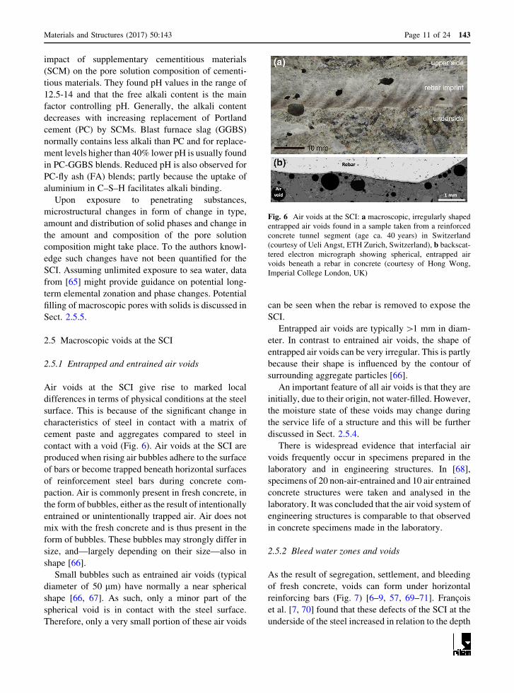
cement paste and aggregates compared to steel in
contact with a void (Fig. 6). Air voids at the SCI are
produced when rising air bubbles adhere to the surface
of bars or become trapped beneath horizontal surfaces
of reinforcement steel bars during concrete com-
paction. Air is commonly present in fresh concrete, in
the form of bubbles, either as the result of intentionally
entrained or unintentionally trapped air. Air does not
mix with the fresh concrete and is thus present in the
form of bubbles. These bubbles may strongly differ in
size, and—largely depending on their size—also in
shape [66].
Small bubbles such as entrained air voids (typical
diameter of 50 lm) have normally a near spherical
shape [66, 67]. As such, only a minor part of the
spherical void is in contact with the steel surface.
Therefore, only a very small portion of these air voids
can be seen when the rebar is removed to expose the
SCI.
Entrapped air voids are typically[1 mm in diam-
eter. In contrast to entrained air voids, the shape of
entrapped air voids can be very irregular. This is partly
because their shape is influenced by the contour of
surrounding aggregate particles [66].
An important feature of all air voids is that they are
initially, due to their origin, not water-filled. However,
the moisture state of these voids may change during
the service life of a structure and this will be further
discussed in Sect. 2.5.4.
There is widespread evidence that interfacial air
voids frequently occur in specimens prepared in the
laboratory and in engineering structures. In [68],
specimens of 20 non-air-entrained and 10 air entrained
concrete structures were taken and analysed in the
laboratory. It was concluded that the air void system of
engineering structures is comparable to that observed
in concrete specimens made in the laboratory.
2.5.2 Bleed water zones and voids
As the result of segregation, settlement, and bleeding
of fresh concrete, voids can form under horizontal
reinforcing bars (Fig. 7) [6–9, 57, 69–71]. Francois
et al. [7, 70] found that these defects of the SCI at the
underside of the steel increased in relation to the depth
Fig. 6 Air voids at the SCI: a macroscopic, irregularly shaped
entrapped air voids found in a sample taken from a reinforced
concrete tunnel segment (age ca. 40 years) in Switzerland
(courtesy of Ueli Angst, ETH Zurich, Switzerland), b backscat-
tered electron micrograph showing spherical, entrapped air
voids beneath a rebar in concrete (courtesy of Hong Wong,
Imperial College London, UK)
Materials and Structures (2017) 50:143 Page 11 of 24 143

of concrete under the steel. However, differences
between upper and underside of the rebar were only
observed when the concrete depth was larger than
150 mm. Mohammed et al. [71] also observed that
gaps were only found under horizontal bars cast in the
top part of reinforced elements and not under those
cast in the bottom part. This is also known as the ‘‘top-
bar effect’’ [70]. In [9], on the other hand, the presence
of a bleed water zone was also found when the height
of concrete below the steel was only 30 mm. SEM
analysis of sections perpendicular to the steel revealed
that the bleed-water zone was typically 100–200 lm
wide [9]. It consisted largely of a void along the steel
surface, interspersed with zones of loosely packed
aggregates particles and cement hydration products
(Fig. 7). The porosity of these zones was coarse.
Similar findings were also made by Horne et al. [57].
Settlement (bulk shrinkage) may cause empty voids
at the underside of the reinforcing steel, but a thin layer
of paste may adhere onto the rebar surface.
Bleed water may also accumulate at the SCI to form
voids of limited lateral dimensions and may appear
similar to entrapped air voids. However, bleed water
voids have a more elongated nature or crescent shape
and are thereby able to achieve a greater contact area
with the rebar surface compared with air voids.
Another major difference is that they are initially
water filled, but can be emptied by chemical shrinkage
and upon drying and, therefore, these bleed water
voids can be mistaken as entrapped air voids. Empty
bleed water voids may be re-filled with water on re-
wetting (cf. Sect. 2.5.4).
One implication of bleed water zones is that the
direction of casting, particularly when producing
laboratory specimens, strongly influences which side
of the reinforcing steel exhibits a more porous zone,
which may, depending on later direction of chloride
ingress, affect the results of corrosion studies.
2.5.3 Cracks, slip, and separation
Tensile and/or flexural loading of reinforced concrete
can cause complex cracking and deformation behav-
iors as schematically illustrated in Fig. 8. Once the
tensile capacity of the concrete is reached, a load-
induced primary crack is formed in the concrete,
which is wider at the concrete tensile surface than at
the rebar, due to the restraining effect of the
reinforcement. The crack usually follows a tortuous
path through the cover and can exhibit minimum width
within the cover, e.g. as it passes between two closely
spaced aggregate particles, and thus can be narrower at
the reinforcement than the crack opening at the
surface. Upon the formation of primary cracks,
internal micro-cracks form around the rebar ribs near
the primary crack due to the transfer of tensile load
through the rebar ribs into the concrete (causing
additional damage at the SCI) and extend with
increasing load (Fig. 8a). Upon further loading, inter-
nal cracks grow from their tips and reach the concrete
surface to be secondary cracks. Finally, at higher steel
stresses, longitudinal cracks are initiated near the rebar
at the faces of primary cracks and then grow towards
the outside of the specimen (Fig. 8b) [72–74]. The
crack formation process is, thereby, divided into two
phases, the crack formation, and the stabilized crack-
ing phase [75]. The crack formation phase is charac-
terized by the development of random cracks at locally
weak sections. During the stabilized cracking phase,
no additional cracks are formed and an increase of load
causes an increase of crack widths only.
The formation of primary, internal, and secondary
cracks is accompanied by damage within the SCI, i.e.
slip and separation. Slip relates to a displacement
discontinuity between the reinforcement and the
surrounding concrete parallel to the reinforcement,
while separation corresponds to a displacement dis-
continuity between the reinforcement and the sur-
rounding concrete perpendicular (in the surface-plane)
Fig. 7 Bleed water zone at the underside of a rebar; backscat-
tered electron micrograph of polished sections showing upper
and lower SCIs in a specimen (Portland cement with 20% fly ash
replacement, w/b = 0.5, hardened under sealed conditions for
1� years) (from [9])
143 Page 12 of 24 Materials and Structures (2017) 50:143

to the reinforcement. The average crack spacing and,
thus, cracking-induced damage along the SCI depends
on the reinforcing bar diameter, bond characteristics,
concrete strength, concrete cover, the distribution of
perpendicular rebars, and effective reinforcement ratio
[76]. While crack widths of primary, internal, and
secondary cracks range between lm and mm, the
extent of these cracks can be up to several meters.
Similarly, cracking-induced damage at the SCI (i.e.
slip and separation) might be several m in length,
while ranging between several lm and mm in width.
2.5.4 Degree of saturation
All available literature on the moisture state in
concrete is related to bulk concrete rather than to the
concrete close to the SCI. At the end of the section,
possible limitations concerning the application of the
data to the SCI are highlighted.
The degree of saturation, S, of concrete depends on
the exposure conditions (moisture and temperature)
and the pore structure, as well as on the moisture
history and pore solution composition. According to
Fagerlund [77, 78] moisture in concrete can be divided
into three ranges: the hygroscopic range, the capillary
range, and the over-capillary range (Fig. 9). The
capillary range and over-capillary ranges are not
differentiated in most literature, but are combined and
referred to as the ‘over-hygroscopic range’. However,
we will distinguish these ranges in discussing the
mechanisms of air-void filling. The (governing)
mechanisms of water uptake are
• Hygroscopic range (0 to about 98% RH): adsorp-
tion and capillary condensation
• Capillary range (up to 100% RH): capillary
suction; capillary saturated at S = Scap
• Over-capillary range: further saturation due to
gradual dissolution of air in the pore water and
diffusion to larger pores or the surface; complete
saturation (all three ranges) at S = 1.
During capillary suction, air bubbles will be
trapped in coarse pores surrounded by a network of
finer pores [78]. Entrapped air bubbles are exposed to
pressure which is inversely proportional to the bubble
radius. Due to over-pressure, air bubbles with smaller
Fig. 8 Schematic
illustration of a damage and
cracking (primary, internal,
and secondary cracks) at
SCI (after [111]), and
b primary and longitudinal
cracks in concrete under
tensile load (after [72]).
Figure not to scale
Fig. 9 Adsorption isotherm showing the three moisture ranges
in concrete (after [77])
Materials and Structures (2017) 50:143 Page 13 of 24 143

radius than approximately 10 lm are according to the
theory not stable at capillary saturation (and not in
fresh paste). Larger bubbles stay initially air-filled, but
will contract due to over-pressure and a small water
volume will surround the bubble. The volume of water
decreases with pore size; for a pore with 10 lm radius
the thickness of the initial water film is estimated at
0.25 lm [78]. It is assumed that the walls of air-filled
pores will, as a minimum, be covered by a layer of
adsorbed water molecules. The layer of adsorbed
water molecules on cement hydrates is approximately
1 nm thick [79].
A detailed description of the mechanism can be
found e.g. in [78, 80]. As mentioned above, enclosed
air bubbles are exposed to over-pressure which is
inversely proportional to the bubble radius. In addi-
tion, the air solubility is proportional to the over-
pressure. Thus, the smaller the pore, the faster the
dissolution of air and water filling of the pore.
Fagerlund [80] proposed two models for water-filling
of air bubbles: Model 1 where absorption takes place
in bubbles of all sizes simultaneously, and Model 2,
where small bubbles are saturated before absorption in
larger bubbles is initiated. According to Fagerlund
[80], Model 2 is most plausible from a thermodynamic
point of view. Assuming, among others, an air bubble
surrounded by saturated paste and a large number of
very big pores at a distance 5 times the radius of the air
bubble, Fagerlund [78] calculated the time for water-
filling of air bubbles of different sizes. The impact of
the pore size and the assumed diffusivity of dissolved
air on the estimated time needed for water-filling is
illustrated in Fig. 10. The absorption time needed to
fill a pore is longer for coarse pores and for materials
with low permeability. Data for the impact of w/c and
binder type on air diffusivity can be found in e.g. [81].
Temperature cycles and freeze/thaw cycles are
observed to increase the sorptivity of concrete
[82, 83]. It is also likely that the rate of filling of air
voids will be affected; but no such information seems
to be available in the literature.
The work of Jacobsen et al. [84] indicated that air
voids might become water filled in the absence of
hydrostatic pressure. Investigating the effect of pre-
conditioning on frost resistance and ascribing absorp-
tion during wet curing in excess of theoretical self-
desiccation to water filling of voids, they calculated
that significant parts of the air voids became water
filled during saturated curing. For the investigated
concretes, the degree of saturation of air voids was
10–65% after water curing for 80 days (cylinders
ø100 9 200 or ø150 9 300 mm, w/b = 0.45, approx.
350 kg/m3 Portland cement, with and without 5%
silica fume, 3–6% air voids of concrete volume).
Hedenblad et al. [85] and De Weerdt et al. [86]
provided data for moisture content in marine concrete
submerged for 14 and 16 years, respectively. Both
found the degree of capillary saturation (Scap) of bulk
concrete in the range of 90–95%. The concrete
compositions varied from w/b = 0.38 and a few
percent of silica fume to w/b in the range of
0.40–0.44 and binders containing Portland cement
and silica fume, fly ash or slag. Higher capillary
saturation was found near the surface, up to 98% in the
outer 10 mm [86]. The absence of full capillary
saturation indicates that no air-pores are water-filled
[87]. According to theory, dissolution of air requires
the establishment of an over-pressure, which requires
capillary saturation of the matrix [77]. In contrast to
the observations on approximately 15 years old sub-
merged marine concrete, Rosenqvist [88] found cap-
illary saturated conditions in a concrete dam (w/
c = 0.55) exposed to fresh water for 55 years. The
concrete at levels 0 and -18.5 m was capillary
saturated to a depth of 20 mm and 200 mm,
respectively.
The moisture state in Norwegian coastal bridges
was investigated by Relling [89, 90]. Selected data
Fig. 10 Estimated time to water-filling of air voids by
dissolution of air [77]. (t = 9.0 9 106 9 r3/d; t: time (s); r: air
void radius (m); d: air diffusivity in water (m2/s). Assumptions:
d = 10–11 m2/s or d = 10–12 m2/s (d = 2 9 10-9 in bulk water if
concentration in kg/m3); solubility of air in water,
s = 2.5 9 10–7 kg/(m3 Pa); spacing between bubbles is supposed
to be 5 times the air-pore radius; density of air at atmospheric
pressure, q = 1.2 kg/m3)
143 Page 14 of 24 Materials and Structures (2017) 50:143

were published in [89]. Table 2 provides an overview
of measured degree of capillary saturation (Scap)
observed in the outer 40–50 mm of the concrete. It
can be observed that the degree of saturation is high in
structural elements exposed to the tidal zone, but not in
the columns and superstructure. In addition to the
impact of exposure, orientation dependent variations
in degree of saturation were observed on the same
structure. Furthermore, Relling [90] found that chlo-
ride contamination affected the sorption isotherm; a
higher moisture content—and thus degree of satura-
tion—was found in chloride contaminated concrete.
Concrete cores from 26 Danish structures of
varying age (built 1953–1985) were investigated in a
1996 project on freeze/thaw performance testing [91].
The investigation included Portland cement concretes
(w/c generally 0.35–0.45) with and without fly ash and
silica fume. The degree of capillary saturation is given
in Table 2. It can be observed that several of the
investigated concrete elements had a high degree of
saturation; especially internally. A few of the con-
cretes were close to or at capillary saturation. All
concrete contained empty voids, which only were
water filled upon pressure saturation.
In summary, macroscopic voids in concrete are
commonly not saturated under exposure conditions
expected in situ. Very few of the investigated in situ
exposed structures were fully capillary saturated. It
may thus be anticipated that only an adsorbed water
film will cover the pore walls of macroscopic void
under in situ exposure conditions. However, theoret-
ical studies, experimental investigations under
laboratory conditions, and investigations of a 55 year
old concrete dam show that air voids might become
filled. The proposed mechanism is that dissolution of
the entrapped air into the surrounding pore water leads
to a gradual filling of the pore with liquid water in the
over-capillary range. In addition to water filling, air
voids might be (partly) filled by re-precipitated
hydrates, typically ettringite.
As mentioned in Sect. 2.4, the microstructure of the
concrete part of the SCI is similar to the ITZ around
aggregates, but different from bulk concrete. Essen-
tially, the capillary porosity at the SCI will be higher
than in the bulk concrete further away. This will affect
the sorption isotherm and thus the degree of saturation
at a given RH as well as the rate of diffusion of air.
Furthermore, possible temperature differences
between steel and concrete might create non-equilib-
rium moisture conditions, e.g. cooling of the steel
could lead to condensation at the steel surface.
2.5.5 Filling of macroscopic pores with solids
According to Samson et al. [92] precipitation of
ettringite is thermodynamically possible in voids and
it is not limited to (partially) saturated conditions. This
is supported by microscopic observations by Jakobsen
[93]. Based on simple calculations indicating that max
2% ettringite of the total volume of concrete can be
formed from the amount of sulfate in a typical
concrete, Samson et al. [92] concluded that air void
filling should not be a problem with regard to freeze/
thaw damage in properly air-entrained concrete.
Table 2 Overview of average moisture content (degree of capillary saturation, Scap) from first 40 or 50 mm in 11 Norwegian costal
bridges and the inland ‘Smedstua’ and in near surface and internal concrete in 26 Danish concrete structures
Structural element/exposure Depth Number Scap CV Ref.
Superstructures (marine) 0–40/50 mm 70 81.9 6.7 [89]
Columns (marine) 0–40/50 mm 114 81.6 6.9
Tidal zone (marine) 0–40/50 mm 45 96.6 2.9
Smedstua, super structure and abutment (inland) 0–40/50 mm 16 76.0 4.6
Exposure to frost and water, with or without salt ‘Surface near’ 14 83 14 [91]
‘Internal’ 14 92 6
Exposure to frost and sometimes water, with or without salt ‘Surface near’ 7 79 8
‘Internal’ 7 88 5
Vertical surfaces exposed to frost, but rarely to water and not to salt ‘Surface near’ 5 75 7
‘Internal’ 5 84 3
CV coefficient of variation
Materials and Structures (2017) 50:143 Page 15 of 24 143

However, accumulation of sulfate due to zoning or
ingress might increase the amount in some areas. This
is illustrated by data from a 55 years old Swedish
concrete dam (w/c = 0.55) exposed to fresh water,
where extensive filling of air voids by ettringite was
found a surface near zone (approx. 3–8 mm) [94].
2.6 Miscellaneous possible characteristics
at the SCI
2.6.1 Neighbouring or intersecting rebars and tie
wires
It is well known that dense detailing of reinforcing
steel can lead to incomplete compaction and locally
porous or segregated concrete [95]. While this is an
extreme case representing bad construction practice,
intersecting rebars and the presence of tie wires
frequently occur in standard engineering structures
(but generally not in laboratory samples). Figure 11
shows a section through a crossing-point of two
perpendicular rebars with macroscopic voids formed
between the bars.
In a laboratory investigation, concrete slabs
(1 m 9 1 m 9 0.1 m, Portland cement, w/c = 0.55,
admixed chloride: 5% by wt. of cement) with perpen-
dicularly intersecting rebars ([10 mm, polished and
degreased) were cast, and cured under sprinkling
water for 28 days [96]. Besides corrosion measure-
ments, concrete samples were taken from the location
of intersecting rebars and far from intersections (by
breaking the specimens) and analysed by means of
scanning electron microscopy (SEM) and mercury
intrusion porosimetry (MIP). The concrete at the SCI
far from the rebar intersections was found to be
significantly less porous than the concrete at the SCI
close to the intersection of two rebars. The results may,
however, have been affected by the presence of
corrosion products that lead to cracking of the
concrete, particularly at rebar intersections.
Tie wires introduce a comparable geometrical
restriction to the flow and compaction of concrete at
the SCI as rebar intersections. In case of welded rebar
mats, apart from geometrical peculiarities the areas
affected by the welding heat may undergo metallur-
gical transformations and show different electrochem-
ical behaviour (thus corrosion resistance) [97].
2.6.2 Presence of spacers in the concrete cover
Spacers are essential components in reinforced con-
crete structures. Spacers (i.e. bar supports, wire chairs,
bolsters, etc.) are used to secure steel reinforcements
within the formwork to prevent movement prior to and
during concreting so that the required cover is
obtained in the finished structure. Spacers are made
of plastic, metal or cementitious materials, and are
available in various sizes and shapes [98–100]. They
generally fall into one of six categories: (a) plastic
spacers with integral clip-on action for horizontal
rebars of 20 mm diameter or less, (b) plastic end
spacers for end cover, (c) plastic wheel/circular
spacers for vertical rebars, (d) cementitious block
spacers for bar size[ 20 mm in heavily-reinforced
sections; (e) continuous line spacers of constant cross-
section to support several bars; and f) steel wire chairs
that may be single, continuous or circular, to support
the top horizontal rebar from lower rebar or to separate
layers of vertical rebars.
There are a number of standards containing spec-
ifications for spacers and for their placement, e.g.
[101–103]. The general rule is that spacers should be
fixed to reinforcing bars at a spacing not exceeding 50
x [ or 1000 mm, where [ is the rebar diameter, and in
staggered rows for parallel bars.
Similar to intersecting/neighbouring rebars (cf.
Sect. 2.6.1) the presence of spacers as solid material
in contact or close proximity of the steel surface likely
affects the local concrete microstructure and gives rise
Fig. 11 Example of voids formed at the intersection of
perpendicular rebars (photograph courtesy of Colin Van
Niejenuis, University of Waterloo, Canada)
143 Page 16 of 24 Materials and Structures (2017) 50:143
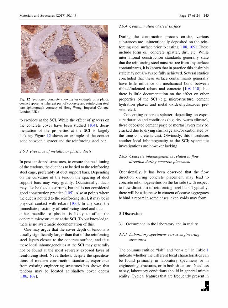
to crevices at the SCI. While the effect of spacers on
the concrete cover have been studied [104], docu-
mentation of the properties at the SCI is largely
lacking. Figure 12 shows an example of the contact
zone between a spacer and the reinforcing steel bar.
2.6.3 Presence of metallic or plastic ducts
In post-tensioned structures, to ensure the positioning
of the tendons, the duct has to be tied to the reinforcing
steel cage, preferably at duct support bars. Depending
on the curvature of the tendon the spacing of duct
support bars may vary greatly. Occasionally, ducts
may also be fixed to stirrups, but this is not considered
good construction practice [105]. Also at points where
the duct is not tied to the reinforcing steel, it may be in
physical contact with rebars [106]. In any case, the
immediate proximity of reinforcing steel and ducts—
either metallic or plastic—is likely to affect the
concrete microstructure at the SCI. To our knowledge,
there is no systematic documentation of this.
One may argue that the cover depth of tendons is
usually significantly larger than that of the reinforcing
steel layers closest to the concrete surface, and thus
these local inhomogeneities at the SCI may generally
not be found at the most severely exposed layer of
reinforcing steel. Nevertheless, despite the specifica-
tions of modern construction standards, experience
from existing engineering structures has shown that
tendons may be located at shallow cover depths
[106, 107].
2.6.4 Contamination of steel surface
During the construction process on-site, various
substances are unintentionally deposited on the rein-
forcing steel surface prior to casting [108, 109]. These
include form oil, concrete splatter, dirt, etc. While
international construction standards generally state
that the reinforcing steel must be free from any surface
contaminants, it is known that in practice this desirable
state may not always be fully achieved. Several studies
concluded that these surface contaminants generally
have little influence on mechanical bond between
ribbed/indented rebars and concrete [108–110], but
there is little documentation on the effect on other
properties of the SCI (e.g. microstructure, cement
hydration phases and metal oxides/hydroxides pre-
sent, etc.).
Concerning concrete splatter, depending on expo-
sure duration and conditions (e.g. dry, warm climate),
these deposited cement paste or mortar layers may be
cracked due to drying shrinkage and/or carbonated by
the time concrete is cast. Obviously, this introduces
another local inhomogeneity at the SCI; systematic
investigations are however lacking.
2.6.5 Concrete inhomogeneities related to flow
direction during concrete placement
Occasionally, it has been observed that the flow
direction during concrete placement may lead to
concrete inhomogeneities on the far side (with respect
to flow direction) of reinforcing steel bars. Typically,
there will be a decrease in content of coarse aggregates
behind a rebar; in some cases, even voids may form.
3 Discussion
3.1 Occurrence in the laboratory and in reality
3.1.1 Laboratory specimens versus engineering
structures
The columns entitled ‘‘lab’’ and ‘‘on-site’’ in Table 1
indicate whether the different local characteristics can
be found primarily in laboratory specimens or in
engineering structures, or in both situations. Needless
to say, laboratory conditions should in general mimic
reality. Typical features that are frequently present in
Fig. 12 Sectioned concrete showing an example of a plastic
contact spacer as inherent part of concrete and reinforcing steel
bars (photograph courtesy of Hong Wong, Imperial College,
London, UK)
Materials and Structures (2017) 50:143 Page 17 of 24 143
concrete structures, but rarely in laboratory samples
are for instance intersections of rebars, tie wires,
spacers, or contaminated rebar surface. Additionally,
the surfaces of reinforcing steel used in laboratory
studies are often different to those used in real
structures. An evaluation [2] of more than 50 publi-
cations describing corrosion tests in concrete revealed
that in a large part of the studies (41%) the rebar
surface condition was not considered important (no
details about mill scale or pre-existing rust layers
reported); while some authors reported that the rebar
surface was sandblasted (12%), polished (32%), or left
in as-received condition (14%).
Regarding the concrete, it is well known that
laboratory investigations—due to their relatively
small specimen dimensions—often use mortar instead
of concrete, which strongly affects the size of aggre-
gates at the SCI. Furthermore, the procedures for
placing, compacting, and curing concrete, which may
affect the concrete microstructure at the SCI, are
different in laboratory studies compared with con-
struction site practice.
Other major differences between laboratory spec-
imens and engineering structures are the age and
exposure conditions. While laboratory samples are
generally young (from a few days or months to at best
a few years) and kept in controlled environment,
engineering structures exhibit service lives in the order
of decades and are subjected to varying environmental
and mechanical loads. Concerning air voids in the
matrix, on the other hand, there seem not to be large
differences between laboratory specimens and engi-
neering structures (only one study [68] available).
Little is, however, known regarding the degree of
water filling of these voids.
3.1.2 Differences among engineering structures
and structural members
Engineering structures around the world may exhibit
marked differences due to differences in national/local
construction policies, building codes, and workman-
ship as well as climatic exposure conditions.
One of the most important factors giving rise to
differences among engineering structures is the type of
concrete used. Over the last century, concrete tech-
nology has undergone major transformations, such as
the advent of concrete admixtures, particularly
superplasticizers that made it possible to produce
concrete with extremely low water/binder ratios. In
conjunction with the increasing use of supplementary
cementitious materials this led to modern concretes
that can hardly be compared to traditional concrete in
terms of many properties such as pore structure, pore
solution chemistry, etc. (see Sect. 2.4).
Although steel is generally considered a much more
homogeneous material than concrete—particularly con-
cerning mechanical material parameters—it has been
shown in Sect. 2.2 that reinforcing steel for concrete
may be very different in terms of bar geometry (ribbed,
indented, twisted, etc. bars), chemical composition and
steel microstructure. In contrast to concrete, however,
codes, standards, and owner policies exercise much less
control over the chemical composition and microstruc-
ture of reinforcing steel. Typically, standards impose
requirements regarding mechanical properties, geomet-
rical specifications, and properties such as weldability or
ductility. Thus, as long as reinforcing steel satisfies these
criteria, it may still exhibit considerable differences in
terms of chemical composition and microstructure,
depending on origin and manufacturer [19].
Similar to concrete, technological evolution over
time has strongly impacted reinforcing steel as
discussed in Sect. 2.2. Concerning rebar geometry,
for instance, up to ca. 1925, primarily steel of round or
square cross section was used [13]. Later on, to
improve bond and anchorage, a wide variety of
irregular (rather than smooth) rebar surface geome-
tries were marketed, including cold twisted square
bars, and various corrugated and deformed bars.
Today, European standard EN 10800, for instance,
distinguishes between ‘‘ribbed steel’’ and ‘‘indented
steel’’ and stipulates tolerances for the dimensions and
number of ribs and indentations, respectively [14].
The geometry of the reinforcing steel (location of ribs)
has an influence on the SCI, e.g. by causing local bleed
water zones under ribs or between indentations and by
defining the location of cracking (see Sect. 2.5).
Additionally, in the 1970/80 s, a transition from
cold-work hardening to thermomechanically strength-
ened steels occurred (Sect. 2.2), which strongly influ-
ences the steel microstructure and surface condition.
Finally, also the type of engineering structure (e.g.
bridge, tunnel, retaining wall, etc.) and its structural
members (slab, beam, column, wall, etc.) will influence
the SCI due to differences in geometry, construction
process, exposure, and mechanical stresses.
143 Page 18 of 24 Materials and Structures (2017) 50:143

In summary, considering the progress in concrete
technology and in reinforcing steel manufacturing,
young (ca.\ 20–30 years) and future structures are
likely to have significantly different SCIs than older
structures. Unfortunately, all long-term field experi-
ence on the durability performance of reinforced
concrete essentially stems from the latter; given the
described significant differences in SCI properties,
this accumulated knowledge may not be applicable to
young and future structures may not be given.
3.2 Interrelations
Figure 13 schematically details possible interrelations
between different characteristics of the SCI. For
example, the geometry of the reinforcing steel bars,
i.e. their diameter and rib shape, their orientation in the
concrete (e.g. vertical or horizontal), will affect the
presence or absence of voids such as bleed water zones
or entrapped air voids in the concrete. To give another
example, the local concrete microstructure and the
phases present impact the composition and amount of
electrolyte in the concrete pore system, which in turn
influences transformations in native rust layers on the
steel surface and the formation and properties of the
passive film on the steel surface.
The figure illustrates that there are numerous
mutual influences between the different characteristics
related to the steel and the concrete. Thus, even when
using an ‘‘identical’’ concrete mix, the SCI will be
different depending on the type of reinforcing steel,
geometrical factors (e.g. casting direction) and also on
later exposure (discussed in the next section).
3.3 Influences of exposure and time
Many characteristics of the SCI are influenced by
environmental exposure and by structural loads
(Fig. 13). Structures are differently exposed to mois-
ture (different relative humidities, direct sunlight,
direct exposure to splash water, or immersed in water)
and often this is also changing over time, e.g. due to
seasonal variations. The same is true for the exposure
temperature. Additionally, chemical exposure may
differ strongly (chlorides, carbon dioxide concentra-
tion, sulfates, etc.). Figure 13 shows how these may
eventually affect the SCI. It is important to recognize,
however, that the cover concrete typically shields the
SCI from environmental exposures, at least for a
certain time. Exceptions are locations with cracks,
honeycombs and other areas where the SCI has direct
access to the exposure environment.
Mechanical stresses may arise from structural loads
as well as from volume changes caused by environ-
mental exposures, such as moisture and/or tempera-
ture changes or chemical exposure (Fig. 13).
Mechanical stresses primarily cause cracking, slip,
and delamination at the SCI, but they may also affect
oxide films,layers, and
scales
concrete
reinforcingsteel
reinforcing steel geometryribs, diameter, orientation, tie wires,
bar intersections, etc.
microstructure &chemical composition
surfaceroughness
passive film- morphology- composition
air voids,bleed water
zones
cracks,slip,
separation
concrete phases µstructure
at SCI
mill scale and native corrosion products
- morphology- composition
mechanicalstresses
volumechanges
structuralloads
moisture
temperature
chloride,CO , sulphate
etc.
environmental exposure and structural loadsmaterials
electrolyte- amount- chemical composition
honeycombs,spacers, ducts,
foreign matter, etc.
contaminationson steel surface:grease, concrete
splatter, etc
2
Fig. 13 Schematic illustration of interrelations between different characteristics at the SCI and of influences by environmental
exposure (temperature, moisture, and chemical exposure) and structural loads
Materials and Structures (2017) 50:143 Page 19 of 24 143
the morphology of the passive layer and of other iron
oxides/hydroxides on the steel surface.
Finally, there are a number of characteristics at the
SCI that change over time, even at constant exposure
conditions because of the slow kinetics of the under-
lying processes. Examples are concrete microstructure
(cement hydration, self-desiccation), passive layer
growth, or transformations in native rust layers or mill-
scales. These time-dependent changes at the SCI may
be understood as ‘‘ageing processes’’, occurring over
long time spans.
4 Conclusions
We made a comprehensive list of possible local
characteristics at the steel–concrete interface (SCI)
and compiled available information regarding their
properties as well as the occurrence of these charac-
teristics in laboratory and in engineering structures.
Given the complexity of the SCI, we suggested a
systematic approach to describe it in terms of local
characteristics (Fig. 2; Table 1). We also described
possible interrelations between these (Fig. 13).
The following major conclusions are drawn:
• The SCI exhibits significant spatial inhomogeneity
along and around as well as perpendicular to the
reinforcing steel bar in terms of material compo-
sition and physical and chemical properties. The
different features that can be found at the SCI span
over a large range of dimensions, i.e. from the
nanometer scale (e.g. passive layer) to the order of
centimeters or even decimeters (e.g. voids or
honeycombs).
• The SCI properties continuously change as a
function of time-dependent exposure conditions,
structural loading, and material ageing (cement
hydration, passive layer growth, etc.).
• The SCI can differ strongly between different
engineering structures and also between different
members within a structure, since some of the
characteristics listed in Table 1 may be present or
absent in different cases. Particular differences are
expected between structures built before and after
the 1970/80 s due to the developments in concrete
technology and in reinforcing steel manufacturing
processes. A single SCI representing all on-site
conditions does not exist.
• SCIs in laboratory-made specimens frequently
exhibit significant differences compared to those
in engineering structures. For instance, any steel
surface cleaning procedures removing mill scale,
native rust layers or affecting surface roughness in
the laboratory is expected to lead to conditions at
the SCI not representative of engineering struc-
tures. Other deviations from engineering structures
that we consider relevant are the common labora-
tory practice of extended curing regime, the
absence of cracks and other mechanical damage
in unloaded laboratory specimens, the possible
differences in concrete microstructure, the fre-
quent absence of rebar intersections, tie wires,
spacers, or welding points, and finally the lack of
long ageing times and realistic exposure.
• In the literature, there is documentation for the
physical and chemical properties as well as the
frequency of occurrence of the following character-
istics: macroscopic voids at the SCI, concrete
microstructure, rebar geometry, and rebar
microstructure. On the other hand, there is a lack of
documentation concerning the following: moisture
conditions in voids at the SCI, steel surface condi-
tions, and characteristics such as rebar intersections,
tie wires, welding points, and contaminations.
• The SCI is known to affect the durability perfor-
mance of reinforced concrete structures. In this
work, large differences of SCI properties were
identified between laboratory samples and engi-
neering structures. Thus, results from laboratory
studies should be applied to engineering structures
with caution. Furthermore, there may be signifi-
cant differences between different engineering
structures (e.g. concerning the time of construc-
tion, construction practices, etc.) and thus, practi-
cal experience from one structure may not be
directly applicable to other structures.
Based on these conclusions, we suggest to use the
systematic approach to the SCI proposed in this work
as a basis to identify from the comprehensive list in
Table 1 those characteristics that have the most
dominant effect on the durability (corrosion) of
reinforced concrete. This will lay the basis for further
research to study the influence of SCI characteristics
on durability in detail. A better understanding of the
SCI and its role in corrosion of steel in concrete are
essential to improve engineering models for the
143 Page 20 of 24 Materials and Structures (2017) 50:143
prediction of the corrosion performance of concrete
structures.
Acknowledgements The authors thank Joost Gulikers for his
comments and careful reading of the manuscript.
Compliance with ethical standards
Conflict of interest The authors declare that they have no
conflict of interest.
Open Access This article is distributed under the terms of the
Creative Commons Attribution 4.0 International License (http://
creativecommons.org/licenses/by/4.0/), which permits unre-
stricted use, distribution, and reproduction in any medium,
provided you give appropriate credit to the original
author(s) and the source, provide a link to the Creative Com-
mons license, and indicate if changes were made.
References
1. Angst UM, Elsener E (in press) Chloride threshold values
in concrete—a look back and ahead. ACI Special Publi-
cation ‘‘Chloride Limits and Thresholds for Concrete
Containing Supplementary Cementitious Materials
(SCM’s)’’
2. Angst U, Elsener B, Larsen CK, Vennesland Ø (2009)
Critical chloride content in reinforced concrete—a review.
Cem Concr Res 39(12):1122–1138
3. Reddy B (2001) Influence of the steel–concrete interface
on the chloride threshold level. PhD thesis, Imperial Col-
lege, London
4. Buenfeld NR, Glass GK, Reddy B, Viles RF (2004) Pro-
cess for the protection of reinforcement in reinforced
concrete. US Patent 6,685,822 B2
5. Glass GK, Reddy B (2002) The influence of the steel
concrete interface on the risk of chloride induced corrosion
initiation. In: COST 521: Final Single Project Reports,
UK6Brussels, pp 227–232
6. Castel A, Vidal T, Francois R, Arliguie G (2003) Influence
of steel–concrete interface quality on reinforcement cor-
rosion induced by chlorides. Mag Concr Res
55(2):151–159
7. Soylev TA, Francois R (2003) Quality of steel–concrete
interface and corrosion of reinforcing steel. Cem Concr
Res 33(9):1407–1415
8. Harnisch J, Raupach M (2011) Untersuchungen zum kri-
tischen korrosionsauslosenden Chloridgehalt unter
Berucksichtigung der Kontaktzone zwischen Stahl und
Beton. Beton- Und Stahlbetonbau 106(5):299–307
9. Angst U (2011) Chloride induced reinforcement corrosion
in concrete; concept of critical chloride content—methods
and mechanisms. PhD thesis, Norwegian University of
Science and Technology, NTNU, Trondheim
10. Michel A, Solgaard AOS, Pease BJ, Geiker MR, Stang H,
Olesen JF (2013) Experimental investigation of the rela-
tion between damage at the concrete–steel interface and
initiation of reinforcement corrosion in plain and fibre
reinforced concrete. Corros Sci 77:308–321
11. Mohammed TU, Otsuki N, Hamada H (2003) Corrosion of
steel bars in cracked concrete under marine environment.
J Mater Civil Eng 15(5):460–469
12. Wayne R (2014) Light and video microscopy. Academic
Press, San Diego
13. Bindseil P, Schmitt MOA (2002) Betonstahle (in German).
Verlag Bauwesen, Berlin
14. European Committee for Standardization (2005) EN
10080:2005—Steel for the reinforcement of concrete.
Weldable reinforcing steel. General
15. Rehm G, Russwurm D (1977) Assessment of concrete
reinforcing bars by the Tempcore process. Beton-
wek ? Fertigteil-Technik 6:300–307
16. Ray A, Mukerjee D, Sen SK, Bhattacharya A, Dhua SK,
Prasad MS, Banerjee N, Popli AM, Sahu AK (1997)
Microstructure and properties of thermomechanically
strengthened reinforcement bars: a comparative assess-
ment of plain-carbon and low-alloy steel grades. J Mater
Eng Perform 6(3):335–343
17. Nikolaou J, Papadimitriou GD (2004) Microstructures and
mechanical properties afteir heating of reinforcing
500 MPa class weldable steels produced by various pro-
cesses (Tempcore, microalloyed with vanadium and work-
hardened). Constr Build Mater 18(4):243–254
18. Cadoni E, Dotta M, Forni D, Tesio N, Albertini C (2013)
Mechanical behaviour of quenched and self-tempered
reinforcing steel in tension under high strain rate. Mater
Des 49:657–666
19. Angst UM, Elsener B (2015) Forecasting chloride-induced
reinforcement corrosion in concrete—effect of realistic
reinforcement steel surface conditions. In: Proceedings of
4th international conference on concrete repair, rehabili-
tation and retrofitting (ICCRRR), Leipzig
20. Okamoto A, Nakamura H (1990) The influence of resid-
ual-stress on fatigue cracking. J Press Vessel Technol
Trans ASME 112(3):199–203
21. Zheng H, Abel AA (1999) Fatigue properties of reinforc-
ing steel produced by TEMPCORE process. J Mater Civil
Eng 11(2):158–165
22. Raman RKS (2006) Characterisation of ‘rolled-in’, ‘frag-
mented’ and ‘red’ scale formation during secondary pro-
cessing of steels. Eng Fail Anal 13(7):1044–1050
23. Ghods P, Isgor OB, McRae GA, Li J, Gu GP (2011)
Microscopic investigation of mill scale and its proposed
effect on the variability of chloride-induced depassivation
of carbon steel rebar. Corros Sci 53(3):946–954
24. Trejo D, Monteiro PJ (2005) Corrosion performance of
conventional (ASTM A615) and low-alloy (ASTM A706)
reinforcing bars embedded in concrete and exposed to
chloride environments. Cem Concr Res 35(3):562–571
25. Wong HS, Zhao YX, Karimi AR, Buenfeld NR, Jin WL
(2010) On the penetration of corrosion products from
reinforcing steel into concrete due to chloride-induced
corrosion. Corros Sci 52(7):2469–2480
26. Poursaee A, Hansson CM (2007) Reinforcing steel passi-
vation in mortar and pore solution. Cem Concr Res
37(7):1127–1133
27. Demoulin A, Trigance C, Neff D, Foy E, Dillmann P,
L’Hostis V (2010) The evolution of the corrosion of iron in
Materials and Structures (2017) 50:143 Page 21 of 24 143

hydraulic binders analysed from 46- and 260-year-old
buildings. Corros Sci 52(10):3168–3179
28. Walsh MT, Sagues AA (2016) Steel corrosion in sub-
merged concrete structures—Part 1: field observations and
corrosion distribution modeling. Corrosion 72:518–533
29. Stefanoni M, Angst U, Elsener B (2015) Local electro-
chemistry of reinforcement steel—distribution of open
circuit and pitting potentials on steels with different sur-
face condition. Corros Sci 98:610–618
30. Ghods P, Isgor OB, Mcrae GA, Cu GP (2010) Electro-
chemical investigation of chloride-induced depassivation
of black steel rebar under simulated service conditions.
Corros Sci 52(5):1649–1659
31. El Haleem SMA, El Wanees SA, El Aal EEA, Diab A
(2010) Environmental factors affecting the corrosion
behavior of reinforcing steel II. Role of some anions in the
initiation and inhibition of pitting corrosion of steel in
Ca(OH)(2) solutions. Corros Sci 52(2):292–302
32. Li L, Sagues AA (2001) Chloride corrosion threshold of
reinforcing steel in alkaline solutions—open-circuit
immersion tests. Corrosion 57(1):19–28
33. Flis J, Pickering HW, Osseo-Asare K (1998) Interpretation
of impedance data for reinforcing steel in alkaline solution
containing chlorides and acetates. Electrochim Acta
43(12–13):1921–1929
34. Rossi A, Puddu G, Elsener B (2007) The surface of iron
and Fe10Cr in alkaline media. In: Raupach M, Elsener B,
Polder R, Mietz J (eds) Corrosion of reinforcement in
concrete—mechanisms, monitoring, inhibitors and reha-
bilitation techniques, EFC Publication no. 3844-60
35. Feng LJ, Yang HY, Wang FH (2011) Experimental and
theoretical studies for corrosion inhibition of carbon steel
by imidazoline derivative in 5% NaCl saturated
Ca(OH)(2) solution. Electrochim Acta 58:427–436
36. Chen YM, Orazem ME (2016) Impedance analysis of
ASTM A416 tendon steel corrosion in alkaline simulated
pore solutions. Corros Sci 104:26–35
37. Sanchez M, Gregori J, Alonso C, Garcia-Jareno JJ, Take-
nouti H, Vicente F (2007) Electrochemical impedance
spectroscopy for studying passive layers on steel rebars
immersed in alkaline solutions simulating concrete pores.
Electrochim Acta 52(27):7634–7641
38. Volpi E, Olietti A, Stefanoni M, Trasatti SP (2015) Elec-
trochemical characterization of mild steel in alkaline
solutions simulating concrete environment. J Electroanal
Chem 736:38–46
39. Williamson J, Isgor OB (2016) The effect of simulated
concrete pore solution composition and chlorides on the
electronic properties of passive films on carbon steel rebar.
Corros Sci 106:82–95
40. Poursaee A (2010) Corrosion of steel bars in saturated
Ca(OH)2 and concrete pore solution. Concr Res Lett 1:90–97
41. Ghods P, Isgor OB, Mcrae G, Miller T (2009) The effect of
concrete pore solution composition on the quality of pas-
sive oxide films on black steel reinforcement. Cem Concr
Compos 31(1):2–11
42. Hansson CM, Poursaee A, Laurent A (2006) Macrocell
and microcell corrosion of steel in ordinary Portland
cement and high performance concretes. Cem Concr Res
36(11):2098–2102
43. Haupt S, Strehblow HH (1987) Corrosion, layer formation,
and oxide reduction of passive iron in alkaline-solution—a
combined electrochemical and surface analytical study.
Langmuir 3(6):873–885
44. Ghods P, Isgor OB, Brown JR, Bensebaa F, Kingston D
(2011) XPS depth profiling study on the passive oxide film
of carbon steel in saturated calcium hydroxide solution and
the effect of chloride on the film properties. Appl Surf Sci
257(10):4669–4677
45. Andrade C, Merino P, Novoa XR, Perez MC, Solar L
(1995) Passivation of reinforcing steel in concrete. Mater
Sci Forum 861:192–194
46. Ghods P, Isgor OB, Carpenter GJC, Li J, McRae GA, Gu
GP (2013) Nano-scale study of passive films and chloride-
induced depassivation of carbon steel rebar in simulated
concrete pore solutions using FIB/TEM. Cem Concr Res
47:55–68
47. Gunay HB, Ghods P, Isgor OB, Carpenter GJC, Wu XH
(2013) Characterization of atomic structure of oxide films
on carbon steel in simulated concrete pore solutions using
EELS. Appl Surf Sci 274:195–202
48. Feng XG, Zuo Y, Tang YM, Zhao XH, Lu XY (2011) The
degradation of passive film on carbon steel in concrete
pore solution under compressive and tensile stresses.
Electrochim Acta 58:258–263
49. Feng XG, Tang YM, Zuo Y (2011) Influence of stress on
passive behaviour of steel bars in concrete pore solution.
Corros Sci 53(4):1304–1311
50. Mammoliti LT, Brown LC, Hansson CM, Hope BB (1996)
The influence of surface finish of reinforcing steel and pH
of the test solution on the chloride threshold concentration
for corrosion initiation in synthetic pore solutions. Cem
Concr Res 26(4):545–550
51. Bensabra H, Azzouz N (2013) Study of rust effect on the
corrosion behavior of reinforcement steel using impedance
spectroscopy. Metall Mater Trans A 44a(13):5703–5710
52. Mohammed TU, Hamada H (2006) Corrosion of steel bars
in concrete with various steel surface conditions. ACI
Mater J 103(4):233–242
53. Akhoondan M, Sagues A (2012) Comparative cathodic
behavior of * 9% Cr and plain steel reinforcement in
concrete. Corrosion 68:1–10
54. Li L, Sagues AA (2004) Chloride corrosion threshold of
reinforcing steel in alkaline solutions—effect of specimen
size. Corrosion 60(2):195–202
55. Angst U, Rønnquist A, Elsener B, Larsen CK, Vennesland
Ø (2011) Probabilistic considerations on the effect of
specimen size on the critical chloride content in reinforced
concrete. Corros Sci 53(1):177–187
56. Scrivener KL, Crumbie AK, Laugesen P (2004) The
interfacial transition zone (ITZ) between cement paste and
aggregate in concrete. Interface Sci 12(4):411–421
57. Horne AT, Richardson IG, Brydson RMD (2007) Quan-
titative analysis of the microstructure of interfaces in steel
reinforced concrete. Cem Concr Res 37(12):1613–1623
58. Baumel A (1959) Die Auswirkung von Betonzusatzmitteln
auf das Korrosionsverhalten von Stahl in Beton (in Ger-
man). Zement-Kalk-Gips 7:294–305
59. Page CL (1975) Mechanism of corrosion protection in
reinforced concrete marine structures. Nature 258:514–515
143 Page 22 of 24 Materials and Structures (2017) 50:143

60. Page CL (2009) Initiation of chloride-induced corrosion of
steel in concrete: role of the interfacial zone. Mater Corros
60(8):586–592
61. Glass GK, Yang R, Dickhaus T, Buenfeld NR (2001)
Backstatered electron imaging of the steel–concrete
interface. Corros Sci 43:605–610
62. Gjorv OE, Monteiro PJM, Mehta PK (1990) Effect of
condensed silica fume on the steel–concrete bond. ACI
Mater J 87(6):573–580
63. Larbi JA (1993) Microstructure of the interfacial zone
around aggregate particles in concrete. Heron 38(1):5–69
64. Vollpracht A, Lothenbach B, Snellings R, Haufe J (2016)
The pore solution of blended cements: a review. Mater
Struct 49(8):3341–3367
65. Jakobsen UH, Weerdt KD, Geiker MR (2016) Elemental
zonation in marine concrete. Cem Concr Res 85:12–27
66. Mielenz RC, Wolkodoff VE, Backstrom JE, Flack HL
(1958) Orgin, evolution, and effects of the air void system
in concrete. Part 1—etrained air in unhardend concrete.
Proc Am Concr Inst 55(7):95–121
67. Richardson M (2007) Degradation of concrete in cold
weather conditions. In: Page CL, Page MM (eds) Dura-
bility of concrete and cement composites. Woodhead
Publishing Limited, Cambridge, pp 282–315
68. Mielenz RC, Wolkodoff VE, Backstrom JE, Burrows RW
(1958) Orgin, evolution, and effects of the air void system
in concrete. Part 4—the air void system in job concrete.
Proc Am Concr Inst 55(10):507–517
69. Castel A, Vidal T, Viriyametanont K, Francois R (2006)
Effect of reinforcing bar orientation and location on bond
with self-consolidating concrete. Aci Struct J 103(4):559–567
70. Zhang RJ, Castel A, Francois R (2011) Influence of steel–
concrete interface defects owing to the top-bar effect on
the chloride-induced corrosion of reinforcement. Mag
Concrete Res 63(10):773–781
71. Mohammed TU, Otsuki N, Hamada H, Yamaji T (2002)
Chloride-induced corrosion of steel bars in concrete with
presence of gap at steel–concrete interface. ACI Mater J
99(2):149–156
72. Goto Y (1971) Cracks formed in concrete around
deformed tension bars. J Am Concr Inst 68:244–251
73. Tammo K, Lundgren K, Thelandersson S (2009) Nonlin-
ear analysis of crack widths in reinforced concrete. Mag
Concr Res 61(1):23–34
74. ACI Committee 224 (2001) Cracking of concrete members
in direct tension. American Concrete Institute, Farmington
Hills
75. Comite Euro-Internationale du Beton (1985) Design
Manual on Cracking and Deformations. Ecole Polytech-
nique Federale de Lausanne, Switzerland
76. Borosnyoi A, Balazs GL (2005) Models for flexural crack-
ing in concrete: the state of the art. Struct Concr 6:53–62
77. Fagerlund G (2006) Moisture design with regards to
durability—with special reference to frost destruction.
Report TVBM-3130. Lund University, Sweden
78. Fagerlund G (2004) A service life model for internal frost
damage in concrete. Report TVBM-3119. Lund institute of
Technology, Sweden
79. Mehta PK, Monteiro PJM (2006) Concrete microstructure,
properties, and materials. McGraw-Hill, New York
80. Fagerlund G (1993) The long time water absorption in the
air-pore structure of concrete. Report TVBM-3051
81. Fagerlund G (1982) The influence of slag content on frost
resistance of hardened concrete
82. Geiker MR, Laugesen P (2001) On the effect of laboratory
conditioning and freeze/thaw exposure on moisture pro-
files in HPC. Cem Concr Res 31(12):1831–1836
83. Wikistrom T (2012) Vattenabsorption i betong under
inverkan av temperatur. Report TVBM-5084
84. Jacobsen S, Marchand J, Boisvert L, Pigeon M, Sellevold
EJ (1997) Frost deicer salt scaling testing of concrete:
effect of drying and natural weathering. Cem Concr Aggr
19(1):8–16
85. Hedenblad G, Andersen A, Nilsson L-O (1998) Faltmat-
ningar i utomhuskonstruktioner (in Swedish). M8:8.
Byggnadsmaterial. Lunds Tekniska Hogskola, Sweden
86. De Weerdt K, Orsakova D, Muller A, Larsen CK, Pedersen
B, Geiker M (2016) Towards the understanding of chloride
profiles in marine exposed concrete, impact of leaching
and moisture content. Constr Build Mater 120(1):418–431
87. Fagerlund G (1993) Frostangrepp – beskrivning av ver-
kande mekanismer. Marina betong-konstruksjoners liv-
slang. Cementa AB, Danderyd
88. Rosenqvist M (2016) Frost-induced deterioration of con-
crete in hydraulic structures—interactions between water
absorption, leaching and frost action. Division of Building
Materials, Lund University, Sweden
89. Relling RH, Sellevold EJ (2005) In-situ moisture state of
coastal concrete bridges. In: Proceedings of international
conference on concrete repair, rehabilitation, and retro-
fitting (ICCRRR), Cape Town, p 191
90. Relling RH (1999) Coastal concrete bridges, moisture
state, chloride permeability and aging effects. PhD thesis.
Norwegian University of Science and Technology
(NTNU). Trondheim
91. Eriksen K, Geiker MR, Grelk B, Laugesen P, Pedersen EJ,
Thaulow N (1997) HETEK. Method for test of the frost
resistance of high performance concrete, performance
testing versus in situ observations. Report No. 93. The
Danish Road Directorate
92. Samson E, Marchand J, Zuber B, Skalny JP (2002)
Ettringite in air voids. In: Proceedings of international
RILEM TC 186-ISA workshop on internal sulfate attack
and delayed ettringite formation, Villars
93. Jakobsen UH (2016) Personal communication
94. Rosenqvist M, Bertron A, Fridh K, Hassanzadeh M (2017)
Concrete alteration due to 55 years of exposure to river
water: chemical and mineralogical characterization. Cem
Concr Res 92:110–120
95. (1997) Durable concrete structures—design guide. Comite
Euro-International du Beton
96. Alhozaimy A, Hussain RR, Al-Zaid R, Al Negheimish A
(2012) Investigation of severe corrosion observed at
intersection points of steel rebar mesh in reinforced con-
crete construction. Constr Build Mater 37:67–81
97. Jang JW, Iwasaki I (1991) Rebar corrosion under simu-
lated concrete conditions using galvanic current mea-
surements. Corrosion 47(11):875–884
98. The Concrete Society (1989) Spacers for reinforced con-
crete. Slough, UK
Materials and Structures (2017) 50:143 Page 23 of 24 143

99. King ES, Dakin JM (2001) Specifying, detailing and
achieving cover to reinforcement, CIRIA C568. Con-
struction Industry Research and Information Association,
London
100. Shaw C (2007) Cover to reinforcement: getting it right.
Struct Eng 31–35
101. American Concrete Institute (1999) ACI 315-99—details
and detailing of concrete reinforcement
102. (2004) ACI SP-66: ACI detailing manual. American
Concrete Institute
103. (2011) DIN EN 13670:2011-03—Execution of concrete
structures (German version of EN 13670)
104. Alzyoud S, Wong HS, Buenfeld NR (2016) Influence of
reinforcement spacers on mass transport properties and
durability of concrete structures. Cem Concr Res 87:31–44
105. (2014) fib bulletin no. 75: Polymer-duct systems for
internal bonded post-tensioning. Federation Internationale
du Beton (fib)
106. Hunkeler F, Matt P, Matt U, Werner R (2005) Prestressing
tendons, stay cables and ground anchors—description of
the systems and lessons learnt from corrosion damages.
Research report ASTRA/AGB2000/470. Swiss Federal
Roads Office, Berne
107. ACI Committee 222 (2014) report on corrosion of pre-
stressing steels (ACI 222.2R-14). American Concrete
Institute (ACI), Farmington Hills
108. Suprenant BA, Malisch WR (1998) How clean must rebar
be? Concr Constr (June):#C980517
109. Taber LH, Belarbi A, Richardson DN (2002) Effect of
reinforcing bar contamination on steel–concrete bond
during concrete construction. ACI Mater J 209:839–862
110. Fu XL, Chung DDL (1995) Linear correlation of bond
strength and contact electrical-resistivity between steel
rebar and concrete. Cem Concr Res 25(7):1397–1402
111. Mimura Y, Yoshitake I, Morimoto K, Hamada S (2010)
Debonding and fracture between deformed bars and early-
age concrete. In: Proceedings FraMCos-7—7th interna-
tional conference on fracture mechanics of concrete and
concrete structures, Jeju
143 Page 24 of 24 Materials and Structures (2017) 50:143