the star itpc upgrade – status and newsrnc.lbl.gov/~jhthomas/public/itpc/lblgroupmtg2016.pdf ·...
TRANSCRIPT

1 Jim Thomas
The STAR iTPC Upgrade – status and news
Jim Thomas, and a cast of thousands
March 15th, 2016
I was not able to find a picture of a cast of thousands, but I was able to find a picture of a thousand casts

2 Jim Thomas
Who, what, when, where, why and how • Who
– BNL, CTU Prague, Kent State, LBL, NPI Prague, SDU Shandong, SINAP Shanghai, UC Davis, UTA, USTC Hefei
• What – Upgrade the inner sectors of the STAR TPC to increase rapidity coverage
and improve tracking and dE/dx at forward rapidities • When
– Proposed to BNL in 2011, presented to Tribble Committee in 2012 – Funding to STAR this month (maybe), ready to take beam in March 2019
• Where – Key Science Institutions: BNL, Kent, LBL, UC Davis, USTC … – Key Projects at BNL (electronics & installation), LBL (sector mechanics), SDU (MWPCs)
• Why – Beam Energy Scan in 2019/2020
• How – Make as few changes to the existing apparatus as possible because this
is a high risk upgrade due to the limited time left in the schedule Alex says I’ve been giving the same talk for 5 years. He is correct. If he starts snoring, just poke him gently to stop the noise but don’t wake him up.

3 Jim Thomas
Beam Energy Scan – Topics and Commitment
BESII: an NSAC endorsed milestone in the LRP

4 Jim Thomas
iTPC PID/acceptance needed for net-proton Kurtosis
• Net proton kurtosis expected to rise as the 4th power of acceptance if ∆yacc < ycorr
• Otherwise the growth is linear … so our results are sensitive to correlation length • Significant measurements at high y are possible due to decrease in error bars
– AMPT simulations shown, significance of measurements wrt theory is important – Xiaofeng Luo and Misha Stephanov have made important contributions to the theory/experiment interface
– http://landau.phy.uic.edu/~misha/highmom-star/acceptance.pdf

5 Jim Thomas
• Systematic study of di-electron continuum from √𝑆𝑆𝑁𝑁𝑁𝑁 = 7.7 – 19.6 GeV – Vector meson suppression due to (possible) Chiral symmetry restoration
• Inner Time Projection Chamber (iTPC) upgrade: reduce systematic error of the background (important), and improves acceptance for signal at 0.4 < Mee < 0.7
• Distinguish models with different ρ-meson broadening mechanisms (e.g. Rapp’s method vs. PHSD)
• Study the total baryon density effect on LMR excess … projected error bars shown
Enable Di-Electron Measurements

6 Jim Thomas
Recent Reviews and Publications
• iTPC Short Summary – https://drupal.star.bnl.gov/STAR/system/file
s/Summary_September14th_iTPC_final.pdf
• iTPC Proposal and CDR – STAR Note SN0629 – https://drupal.star.bnl.gov/STAR/starnotes/
public/sn0619
• Technical Design Report – STAR Note SN0644 – https://drupal.star.bnl.gov/STAR/starnotes/
public/sn0644
• Cost and Schedule review – https://indico.bnl.gov/conferenceDisplay.py
?confId=1711

7 Jim Thomas
The STAR Detector at RHIC

8 Jim Thomas
Sector Insertion – special tools required ⇒ BNL

9 Jim Thomas
Goal: Hermetic coverage & better acceptance
60 cm
190 cm
• Currently, the outer pad plane is hermetic while the inner pad plane is not • Goal: Add more pad rows on the inner sector, 2X total pad count
The upgrade will provide better momentum resolution, better
dE/dx resolution, and improved acceptance at high η

10 Jim Thomas
New Pad Plane design and layout
A corner of the new inner pad plane layout by John Hammond & Bob Scheetz
Row 40 Row 39
Pad Row # of Pads1 522 543 564 585 606 627 628 649 66
10 6811 7012 7213 7414 7415 7616 7817 8018 8219 8420 8621 8622 8823 9024 9225 9426 9627 9828 9829 10030 10231 10432 10633 10834 11035 11036 11237 11438 11639 11840 120
TOTAL 3440Momentum (and spatial) resolution not strongly dependent on pad design within the range studies … it’s the extra rows that are important

11 Jim Thomas
New PadPlane Performance
• Efficiency as a function of η and pT
• Acceptance increases from |η| < 1 to |η| < 1.5
The pad response function for the outer sector is shown by the black line, the existing inner sector by the blue line, and the proposed inner sector by the red line. The pad spacing is 6.7 mm, 3.35 mm, and 5 mm respectively.

12 Jim Thomas
Project Scope: Mechanics, Electronics & MWPCs
• hi

13 Jim Thomas
Major Items: Definition & Scope
Pad Plane with larger (5x16) pads, hermetic coverage
Strongback Outer Sector, but a good proxy for Inner Sector discussion
Wire Mounts for Grids Wire Planes: Gated Grind, Cathode Grid, and Ground Grid
14 Jim Thomas
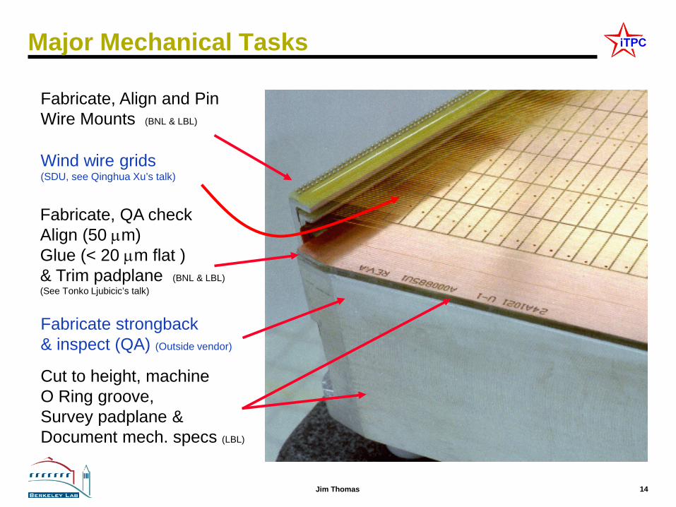
Major Mechanical Tasks
Fabricate, Align and Pin Wire Mounts (BNL & LBL)
Cut to height, machine O Ring groove, Survey padplane & Document mech. specs (LBL)
Fabricate, QA check Align (50 µm) Glue (< 20 µm flat ) & Trim padplane (BNL & LBL) (See Tonko Ljubicic’s talk)
Wind wire grids (SDU, see Qinghua Xu’s talk)
Fabricate strongback & inspect (QA) (Outside vendor)

15 Jim Thomas
Cost Drivers
• Padplane & Electronics (BNL) – $96.4K for Padplanes – $1.4 M (approximately) for DAQ boards & electronics
• Strongback (Outside vendor, BNL procurement) – $418.9 K – Two preliminary vendor quotes & initial experience at UT Austin
• Assembly of Padplane & Strongbacks (LBL) – $551.8 k – Berkeley is the preferred location for the gluing of the PadPlane, and
assembly of the Strongback and Wire Mounts – Close proximity to Engineers and Technicians who previously
worked on STAR (circa 1995) – Nicely integrated Assembly shop, Machine Shop & Survey shop
We are proposing to bring the Assembly work to LBL
(primarily work for Eric Anderssen’s group in B77) This will need active support from NSD in order to succeed
16 Jim Thomas
Schedule Drivers relevant to work at LBL • Strongback
– We must go to an outside vendor with multiple machines in order to fabricate the strongbacks
– UT Austin is no longer an option – 6 to 8 weeks (.vs. 1 year), preliminary quotes from outside vendors
• Padplane – Work is being done by STAR Electronics group which is one of the
projects greatest strengths. However, sharing the wealth of good manpower is a competitive process. Work has been delayed. (Affects QA and prototyping schedules)
• Assembly – Schedule is fast paced, only ~2 days allowed per sector – Tooling and time to set up work space
• Critical Path – The PadPlane and the Strongback are simultaneously on the critical path
– Both must be available in Berkeley on August 1st – Berkeley assembly shops are busy with ALICE upgrade work, already
– Only way to deal with this is to start early and Multi-task
17 Jim Thomas
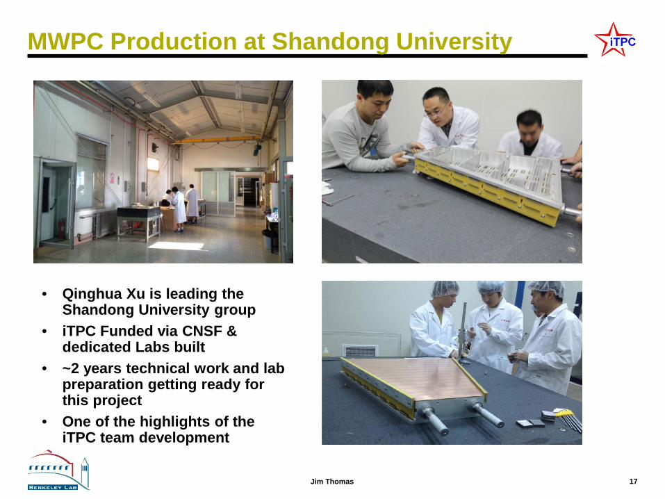
MWPC Production at Shandong University
• Qinghua Xu is leading the Shandong University group
• iTPC Funded via CNSF & dedicated Labs built
• ~2 years technical work and lab preparation getting ready for this project
• One of the highlights of the iTPC team development

18 Jim Thomas
Full Project Summary schedule
Current schedule has STAR ready for data taking March 1 2019, with ~1.5 month of commissioning. Key goal of project is to have upgrade complete for Run-19. Critical path goes through electronics path (SAMPA chips), installation and test, but the mechanical systems are essentially on the critical path, too.
Calendar Year 2016 2017 2018 2019 Q1 Q2 Q3 Q4 Q1 Q2 Q3 Q4 Q1 Q2 Q3 Q4 Q1 Q2 Q3 Q4 Mechanical padplane Strongback production Padplane Assembly Assemble MWPC Sector Installation Electronics RDO SAMPA FEE Electronics installation Roll-in and commisioning Insertion Tool

19 Jim Thomas
Cost to DOE
The NSF-China contribution is not included (~$1.0 M US) The cost of Installation tooling not included (~$650 K US)
WBS FY16 FY17 FY18 Conting Total
1 Mgt 50.6 94.5 97.4 45.5 288.0
2 Padplane 96.4 0.0 0.0 32.8 129.2
3 Mechanics 949.9 228.0 14.8 250.3 1,443.0
4 Installation 0.0 0.0 136.4 31.2 167.6
5 Electronics 45.7 310.3 934.3 238.4 1,528.6
Total DOE 1,142.6 632.8 1,182.8 598.1 3,556.4
Ayk$
20 Jim Thomas
Risk – high level summary
• Technical – Better than 20 µm flatness requirement for PadPlane+Strongback – Excellent alignment of wires and padplane (20 µm), excellent control
over tension on wires – Bromine free materials
– A vigorous QA plan is essential – We have the elements of a good QA plan in place but we also need
the will to stick to it
• Schedule – We are relying upon the ALICE SAMPA chip for the iTPC electronics – Pre-production prototype step for Strongbacks (etc) is in jeopardy
– Schedule is tight and so we may be forced to skip traditional steps – Minor schedule slips can easily eliminate the opportunity to develop
tooling and practice our techniques on a prototype
• Management – Major activities must complete this year, requires $$$ quickly – For example, we haven’t spent any money this fiscal year

21 Jim Thomas
Summary
• The iTPC upgrade will enable new physics with BES II – Enhanced Kurtosis measurements – Enhanced Di-electron measurements
• New PadPlane & Faster electronics – 40 pad rows, 5 mm x 16 mm pads (center to center spacing), full coverage – Increase TPC acceptance from < 1.0 to < 1.5 units of pseudo-rapidity
• Strongback is 95% the same as before – Fix the grid-leak problem
• Cost and Schedule concerns – Very tight schedule. No float. – We are skipping the “prototype” step for nearly all work in the US – Final PadPlane, Strongbacks & wire mounts due in Berkeley on August 1st – Money must move from BNL to LBL very quickly, can it be done? – Spending large amounts of money – wisely – is hard to do
An upgraded TPC with $500K of new work for NSD and Engineering

22 Jim Thomas
Backup Slides

23 Jim Thomas
The TPC is the Heart of STAR
• STAR without the TPC

24 Jim Thomas
Mean, Variance, Skewness and Kurtosis
• Hi
Mean
Variance
Skewness
Increasing Kurtosis
Transfer from shoulders to center and to extremes

25 Jim Thomas
40 Pad Rows fit perfectly with the existing grid
(Old)
• Identical pad response function on both ends of grid • No need to change grid; wire locations remain the same! • No need to add more ABDB or wire mount channels (good!)
Anode wires spaced 4 mm apart (horizontally), Ground Shield and Gated grids spaced 1 mm apart
Remember this region with a gap between the grids… we will come back to it

26 Jim Thomas
Changes since previous (1995) design • 3D CAD design – (lower fabrication & inspection costs) • Slots for electronics move down by 0.221” • Wall to mitigate gridleak problem
GARFIELD simulations of ions flowing away from the STAR TPC anode wires when the Gated Grid is closed. There is a 1.2 cm gap between the Inner and Outer sectors that is not covered by the Gated Grids. This gap allows ions to flow out of the MWPC region and into the tracking volume of the TPC. Putting a -690 volt bias (left panels) on the wall reduces the flow of ions, while the “L” shaped wall (right panels) completely stops the flow of ions. The “L” shaped wall was held at 0 volts in this simulation.
Slots for electronics are lower by 0.221” than previously. Otherwise, the same.

27 Jim Thomas
The Alice Solution to the Grid Leak problem • Multiple thick anode wires near the boundaries of the sectors • A wall – to terminate the field lines from the Anode wires with
ground potential and “cover” potential (match field gradient)
28 Jim Thomas
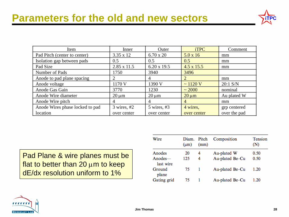
Parameters for the old and new sectors
Item Inner Outer iTPC Comment Pad Pitch (center to center) 3.35 x 12 6.70 x 20 5.0 x 16 mm Isolation gap between pads 0.5 0.5 0.5 mm Pad Size 2.85 x 11.5 6.20 x 19.5 4.5 x 15.5 mm Number of Pads 1750 3940 3496 Anode to pad plane spacing 2 4 2 mm Anode voltage 1170 V 1390 V ~ 1120 V 20:1 S/N Anode Gas Gain 3770 1230 ~ 2000 nominal Anode Wire diameter 20 µm 20 µm 20 µm Au plated W Anode Wire pitch 4 4 4 mm Anode Wires phase locked to pad location
3 wires, #2 over center
5 wires, #3 over center
4 wires, over center
grp centered over the pad
Pad Plane & wire planes must be flat to better than 20 µm to keep dE/dx resolution uniform to 1%

29 Jim Thomas
Strongback Construction Prototype
Figure 54: A prototype inner sector strongback is shown during fabrication at the University of Texas (circa 2013). The sector was machined out of a single piece of aluminum. Dimensions are: ~27 inches tall, ~25 inches wide and weight 73 lbs. The sector is viewed from the backside; the side upon which the electronics and cooling manifolds will eventually be mounted.

30 Jim Thomas
Wire locations near the gap will not change
• The location of the wires near the inner/outer gap cannot change – Position and total number of wires on each plane remains the same
• Because … it is not possible to add more wires – The full extent of the side mounted wire mounts are already used

31 Jim Thomas
Sector Wire Geometry – special notes
Wires are phase locked to the pad locations. 4 wires located over each pad row. We can probably tolerate a phase shift of 100 microns.
Ground wires placed directly over the Anode wires to limit sparking to pad plane.

32 Jim Thomas
Inner sector detail

33 Jim Thomas
Inner / Outer sector detail
• Note that inner and outer pad planes are not at the same height • Pad plane to wire grid heights not the same (4/4/6 vs 2/2/6) • 3 mm gap between sectors, this is an issue during installation

34 Jim Thomas
Location of Wires and Pads Radius (Y) Description
0.00 Center of STAR Detector (vtx)
498.80 Bottom of Full size PC Board
512.70 Tertiary Fiducial L & R
519.05 Strongback Bottom Edge
530.00 Gated Grid Wire 1
531.00 Gated Grid Wire 2
532.00 Anode Wire 1 & GG W-3
536.00 Anode Wire 2 & GG W-7
540.00 Anode Wire 3 & GG W-11
540.25 Secondary Fiducial
544.00 Anode Wire 4 & GG W-15
548.00 Anode Wire 5 & GG W-19
558.00 Pad Row 1 - Center
574.00 Pad Row 2 - Center
1166.00 Pad Row 39 - Center
1179.45 Primary Fiducial
1182.00 Pad Row 40 - Center
1192.00 Anode Wire 166 & GG W-663
1196.00 Anode Wire 167 & GG W-667
1200.00 Anode Wire 168 & GG W-671
1204.00 Anode Wire 169 & GG W-675
1204.85 Alternate Primary Fiducial
1208.00 Anode Wire 170 & GG W-679
1209.00 Gated Grid Wire 680
1210.00 Gated Grid Wire 681
1214.32 Strongback Top Edge
1220.67 Tertiary Fiducial L & R
1235.42 Top of Full size PC Board
Repeat pad rows every 16 mm
Wire Locations are the same as before except for the replacement of 6 thin anode wires with larger diameter anode wires (0.020 mm ⇒ 0.125 mm)
References: LBL Drawings 24A055, 24A373, 24A374
LAST ANODE WIREØ.125mm BeCu , Au platedOUTER : 2 WiresINNER : 6 Wires (2 in old design)TOTAL : 8 Wires per Sector (4 in old design)
ANODE GRID WIREØ.020mm W, Au platedspacing 4mmOUTER : 170 WiresINNER : 164 Wires (168 in old design)TOTAL : 334 Wires per Sector (338 in old design)
SHIELD GRID WIREØ.075mm BeCu , Au platedspacing 1mmOUTER : 689 WiresINNER : 681 WiresTOTAL : 1,370 Wires per Sector
GATED GRID WIREØ.075mm BeCu , Au platedspacing 1mmOUTER : 689 WiresINNER : 681 WiresTOTAL : 1,370 Wires per Sector

35 Jim Thomas
Strongback – Preliminary quotation #1

36 Jim Thomas
Strongback – Preliminary quotation #2

37 Jim Thomas
Critical Dimensions for the TPC Item Dimension Comment
Length of the TPC 420 cm Two halves, 210 cm long Outer Diameter of the drift volume 400 cm 200 cm radius Inner Diameter of the drift volume 100 cm 50 cm radius Distance: cathode to ground plane 209.3 cm Each side Cathode 400 cm diameter At the center of the TPC Cathode potential 28 kV typical Drift gas P10: 90% Ar, 10% CH4 He-Ethane as an option Drift Velocity 5.45 cm/µsec typical Transverse diffusion (σ) 230 µm/√cm 135 V/cm & 0.5 T Longitudinal diffusion (σ) 360 µm/√cm 135 V/cm & 0.5 T Magnetic Field 0, ±0.25 T, ±0.5 T Solenoidal

38 Jim Thomas
Average mass distributions ( ±10°, 1.5 < η < 2.0 )
FEE 3.60 % FEE mounting bracket 3.45 % FEE rib 0.45 % FEE socket 0.15 % Cooling manifold 3.25 % RDO card 0.90 % Ribs 2.70 % Sector G10 0.45 % Sector Aluminum 3.20 % Cables ~1% (estimate) FEE sub Total 7.65% Total 19.15%
Table 6: The average radiation length budget for the components associated with a TPC inner sector (circa 1993) averaged over the fiducial volume of the sector. The average takes out the lumps in the mass distribution (for better or worse) but also illustrates how the budget for the Al on the front face compares to the electronics and cooling budget. The sector data have been averaged over a range from 1.5 < η < 2.0 and -10 < φ < 10 degrees. Geant simulations courtesy of Irakli Chakaberia.