the spe foundation through member donationsthe spe … · • main difference is in the cryogenic...
TRANSCRIPT
Primary funding is provided by
The SPE Foundation through member donationsThe SPE Foundation through member donations and a contribution from Offshore Europe
The Society is grateful to those companies that allow theirThe Society is grateful to those companies that allow their professionals to serve as lecturers
Additional s pport pro ided b AIMEAdditional support provided by AIME
Society of Petroleum Engineers Distinguished Lecturer Programwww.spe.org/dl
1

LNG Basicsfor Petroleum Engineersfor Petroleum Engineers
Michael Choi
2

Present an Overview of LNG Plantese Ove v ew o NG• Why LNG?• Typical Multi Trains Plant• Typical Multi-Trains Plant• Pre-Treatment Required• Unique Auxiliary Facilitiesq y• Natural Gas Liquefaction
Thermodynamics• Commercial Liquefaction
Oman LNG Plant
• Commercial Liquefaction Processes
• Equipment for LiquefactionOman LNG Plant • Novel Plant Concepts
• Concluding Remarks
3

Stranded Gas Looking for Markets• LNG Proved to be Most Economic for Distances >1,500 Mile• Transported in Insulated Tankers @ -162C & 1 atm.
V l R d ti f 600 1• Volume Reduction of 600:1
SupplyDemandDemand
4
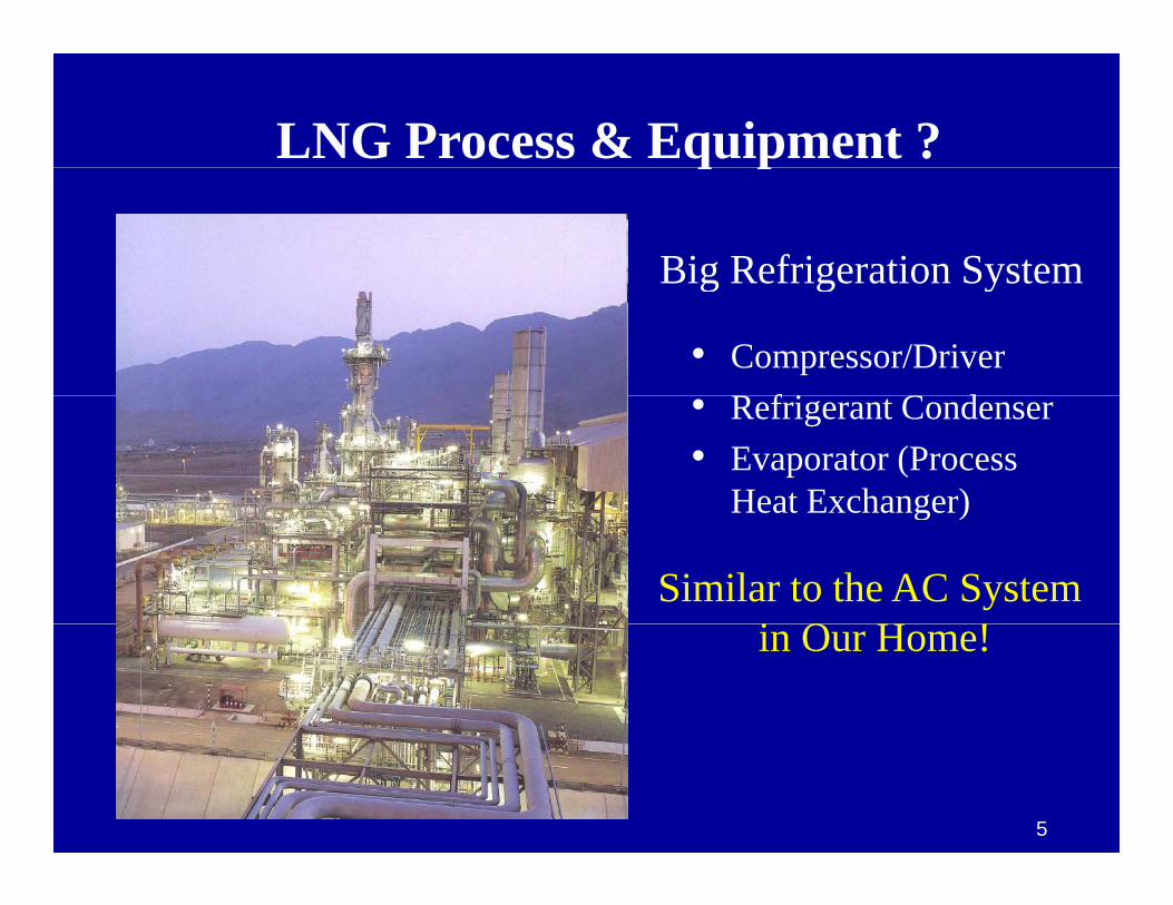
LNG Process & Equipment ?q p
Big Refrigeration System
• Compressor/DriverR f i C d
Big Refrigeration System
• Refrigerant Condenser• Evaporator (Process
Heat Exchanger)Heat Exchanger)
Similar to the AC Systemi O H !in Our Home!
5

Typical 2-Train LNG PlantFuelMake-
Up FuelGas
Gathering Train 1
Inlet Gas Reception
Inlet Gas Treating
NGL Recovery
Liquefaction LNG Storage
LNG
Gas
Liquid
g
1.7 Bcfd
NGL Fractionation
Train 2
9 Mtpa (1.2 Bcfd)
Condensate Stabilization
Propane Storage
Butane
Propane
Butane
.73 Mtpa(27 Mbpd)
Butane Storage
Condensate Storage
Butane
Condensate
(17 Mbpd).5 Mtpa
1 2 MtStorage(34 Mbpd) 1.2 Mtpa
6

Typical 2-Train LNG PlantFuelMake-
Up FuelGas
Gathering Train 1
Inlet Gas Reception
Inlet Gas Treating
NGL Recovery
Liquefaction LNG Storage
LNG
Gas
Liquid
g
1.7 BcfdInlet Gas Reception
NGL Fractionation
Train 2
9 Mtpa (1.2 Bcfd)
Inlet Gas Reception• Pipeline Manifold• Pig Receivers• I l t S t
Condensate Stabilization
Propane Storage
Butane
Propane
Butane
.73 Mtpa(27 Mbpd)
• Inlet Separator• Slug Catcher
Condensate Stabilization Butane Storage
Condensate Storage
Butane
Condensate
(17 Mbpd).5 Mtpa
1 2 Mt
Condensate Stabilization• Multi-Stage Column• Vapor Compressor
10 12 i RVP Storage(34 Mbpd) 1.2 Mtpa • 10-12 psia RVP
• De-Odorized7

Typical 2-Train LNG PlantFuelMake-
Up FuelGas
Gathering Train 1
Inlet Gas Reception
Inlet Gas Treating
NGL Recovery
Liquefaction LNG Storage
LNG
Gas
Liquid
g
1.7 Bcfd
NGL Fractionation
Train 2
9 Mtpa (1.2 Bcfd)NGL Fractionation
• DeethanizerV C i
Condensate Stabilization
Propane Storage
Butane
Propane
Butane
.73 Mtpa(27 Mbpd)
• Vapor Compression• Depropanizer & Treating
• 95% & 200 psig VP Butane Storage
Condensate Storage
Butane
Condensate
(17 Mbpd).5 Mtpa
1 2 Mt
• <.5ppm H2S & <15ppm S• Debutanizer & Treating
• 95% & 70 psig VP @100F Storage(34 Mbpd) 1.2 Mtpa
7
95% & 70 psig VP @100F• <.5ppm H2S & <15ppm S

Typical 2-Train LNG PlantFuelMake-
Up FuelGas
Gathering Train 1
Inlet Gas Reception
Inlet Gas Treating
NGL Recovery
Liquefaction LNG Storage
LNG
Gas
Liquid
g
1.7 Bcfd Inlet Gas Treating
NGL Fractionation
Train 2
9 Mtpa (1.2 Bcfd)
Inlet Gas Treating• Amine for CO2 & H2S Removal
• <50 ppm & < 4 ppm• S lf R U it if H S
Condensate Stabilization
Propane Storage
Butane
Propane
Butane
.73 Mtpa(27 Mbpd)
• Sulfur Recovery Unit if H2S• Mol Sieve Dehydration*
• < 100 ppbButane Storage
Condensate Storage
Butane
Condensate
(17 Mbpd).5 Mtpa
1 2 Mt
• Mercury Vapor Removal*• Activated Carbon Adsorber
Storage(34 Mbpd) 1.2 Mtpa
7

Typical 2-Train LNG PlantFuelMake-
Up FuelGas
Gathering Train 1
Inlet Gas Reception
Inlet Gas Treating
NGL Recovery
Liquefaction LNG Storage
LNG
Gas
Liquid
g
1.7 Bcfd NGL Recovery
NGL Fractionation
Train 2
9 Mtpa (1.2 Bcfd)
NGL Recovery• Scrub Column/KO after C3 Pre-Cool• Primarily C4+ to Prevent Freezing• LNG H t V l I t t f US &
Condensate Stabilization
Propane Storage
Butane
Propane
Butane
.73 Mtpa(27 Mbpd)
• LNG Heat Value Important for US & European Markets• 1,070 btu/scf Max
Butane Storage
Condensate Storage
Butane
Condensate
(17 Mbpd).5 Mtpa
1 2 Mt
• Need Turbo-Expander for High C3+ Removal
Storage(34 Mbpd) 1.2 Mtpa
7

180,000 M3 LNG Tank180,000 M3 LNG Tank
• Full-Containment Tank to Reduce Impound Area & Improve SafetyImpound Area & Improve Safety
• Approx. 75M Dia x 40M H• Insulated for <.05%/D of Boil-off
• Total Capacity Based on Tanker Size (135,000 M3)
• Plus 4+-Days Production• Top Entry In-Tank Pumpsp y p
8
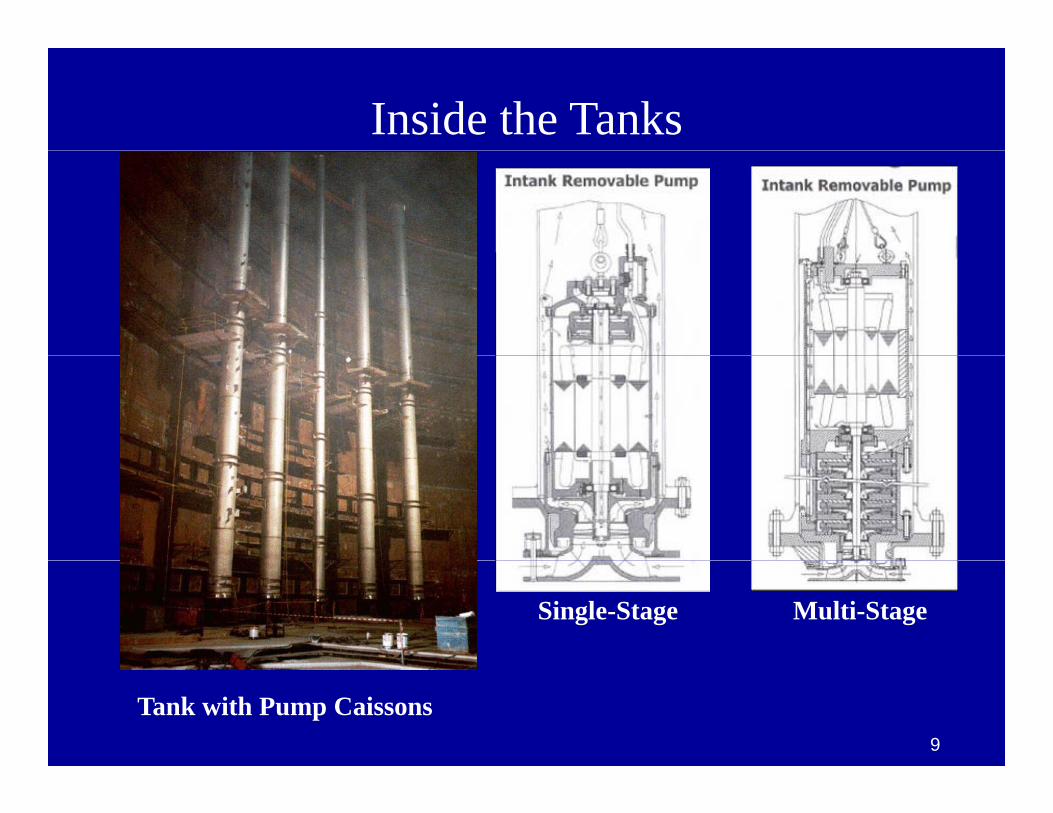
Inside the Tanks
Single-Stage Multi-Stage
Tank with Pump Caissons9

LNG Loading System
• 16” Chiksan Typeyp• 3+1 – LNG Arms
• 3,500 M3/Hr/Ea.• 10,500 M3/Hr• 140K M3 Tanker
• 4+1 – Systems• 14,000 M3/Hr• Qmax & Qflex• Qmax & Qflex• 200K+ M3
• 1 – Vapor Return1 Vapor Return
10

Cost of Refrigeration
MethaneMethaneor Nitrogen
Cost/BtuRemovedRemoved
Air/WaterPropaneEthylene
-162C 25CTemperature
p
11

Natural Gas Liquefaction Processes25C
Gas Cooling
TemperatureCondensation
Min. DT
Liquid
-162C
Sub-cooling
H (Enthalpy - Heat Removed)12

Cascade LNG Process• Most Straight Forward of All Processes• Kenai Plant Continuous Operation 1969
80F PropaneRefrig.
1st Stage
2 d SCoP Optimized
80F PropaneRefrig.
1st Stage
2 d SCoP Optimized
PropaneRefrig.
1st Stage
2 d S
PropaneRefrig.
1st Stage
2 d SCoP OptimizedKenai Plant Continuous Operation 1969
• CoP License, Plant Build by Bechtel
Tem
pera
ture
2nd Stage
3th Stage
1st Stage
2nd Stage
Cascade Refrigerant Cycle
Tem
pera
ture
2nd Stage
3th Stage
1st Stage
2nd Stage
Cascade Refrigerant Cycle2nd Stage
3th Stage
2nd Stage
3th Stage
Ethylene Refrig1st Stage
2nd Stage
Cascade Refrigerant Cycle
1st Stage
-260F
H (Enthalpy - Heat Removed)
Methane Refrig. .-260F
H (Enthalpy - Heat Removed)
..2nd Stage
3th Stage
Kenai AlaskaKenai, Alaska
13

C3 Precooled – Mixed Refrigerant Process80F Propane
Refrig.
1st Stage Propane PreCooledMixed Refrigerant Cycle
80F80F PropaneRefrig.
1st Stage Propane PreCooledMixed Refrigerant Cycle
PropaneRefrig.
1st Stage
PropaneRefrig.
1st Stage Propane PreCooledMixed Refrigerant Cycle
• Most Widely Used Licensed by APCI• 1st Plant in Algeria Operating Since 1972
Tem
pera
ture
2nd Stage
3th Stage
Mixed Refrigerant
Tem
pera
ture
Tem
pera
ture
2nd Stage
3th Stage
Mixed Refrigerant
2nd Stage
3th Stage
2nd Stage
3th Stage
Mixed Refrigerant
g p g• Plants Built by KBR, Chiyoda, JGC, FW
-260F
H (Enthalpy - Heat Removed)
-260F
H (Enthalpy - Heat Removed)
-260F
H (Enthalpy - Heat Removed)
QatarGas LNG PlantQ
14

APCI AP-X Process
• Largest Train Capacity @ 8 Mtpa• Overcome Spiral Wound MCHE Limit APCI Suppliesp• First Unit Started in 2009 (QG-II)• No Plants Outside of Qatar
• Process Design• Cold Boxes• Spiral Wound Exchangerp g• Turbo-Expanders
15

All Processes Use Similar Equipment
GE MS7001 FB Gas Turbine• Most New Plants Use Large Gas Turbine (& Combined
Cycle) to Drive Refrigerant Compressors• Some Older & Smaller Trains Have Steam Turbine DrivesSome Older & Smaller Trains Have Steam Turbine Drives• Many Peak Shaving Plants on Electric Drives• Use Large Process Type Centrifugal Compressorsg yp g p• Main Difference is in the Cryogenic Heat Exchangers
16

Main Cryogenic Heat ExchangerMain Cryogenic Heat ExchangerUse by Mixed Refrigerant ProcessUse by Mixed Refrigerant Process
Ai P d t & Ch i lAir Products & Chemicals& Linde: Spiral Wound Ex.• Max. Diameter: 5,030mma . a ete : 5,030• Height: ~55m• Stainless Steel Core• 25mm Aluminum Tubing• Externally Insulated• Chill & Liquefy GasChill & Liquefy Gas
– From –34ºC to –152ºC– At 55 to 69 Barg
17

APCI’s MR Main Cryogenic Heat Exchanger (MCHE)Spiral Wound DesignSpiral Wound Design
18
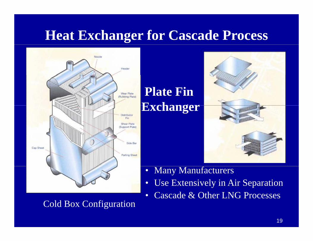
Heat Exchanger for Cascade Process
Plate FinExchangerExchanger
• Many Manufacturers• Use Extensively in Air Separation• Cascade & Other LNG Processes
Cold Box ConfigurationCascade & Other LNG Processes
19
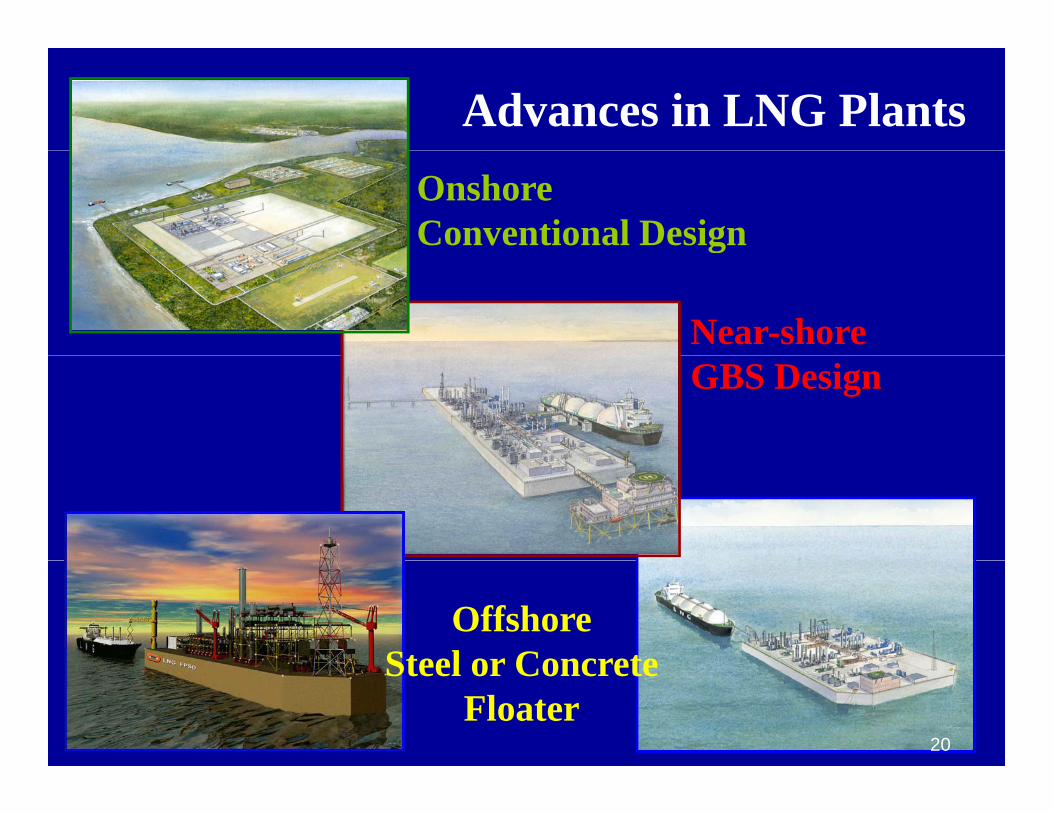
Advances in LNG PlantsOnshoreConventional Design
Near-shore
g
GBS Design
OffshoreSteel or ConcreteSteel or Concrete
Floater20

Conclusions• LNG Liquefaction Process Same as AC System in Our Home• Pre-Treatment Facilities Can Dwarf Liquefaction System
– Mole Sieve Dehydration & Mercury Removal RequiredMole Sieve Dehydration & Mercury Removal Required– Gas Treating & NGL Extraction May be Needed– Stabilized Condensate & Fractionated NGL Add Value
LNG E h St & L di S t A U i• LNG Exchangers, Storage & Loading Systems Are Unique• Commercial Liquefaction Processes Well Proven, Robust & Can
be Optimized for Plant Size, Gas Composition, Sales & Commercial NeedsCommercial Needs
• Novel Near-Shore & Offshore Floating Concepts Are Developed
21
LNG ?
22

Your Feedback is ImportantpEnter your section in the DL Evaluation Contest by
completing the evaluation form for this presentation :completing the evaluation form for this presentation :
Click on: Section EvaluationClick on: Section Evaluation
Society of Petroleum Engineers Distinguished Lecturer Programwww.spe.org/dl 26
http://research.spe.org/se.ashx?s=705E3F13128DC9C5