the slac pulsed x-ray facility* · the pulsed nature of the electron beam creates problems in the...
TRANSCRIPT

I SLAC - PUB - 3968 May 1986 (4
THE SLAC PULSED X-RAY FACILITY*
N. E. IPE, R. C. MCCALL AND E. D. BAKER
Stanford Linear Accelerator Center
Stanford University, Stanford, California, QdSOS
ABSTRACT
The Stanford Linear Accelerator Center (SLAC) operates a high energy (up
to 33 GeV) linear accelerator delivering pulses up to a few microseconds wide.
The pulsed nature of the electron beam creates problems in the detection and
measurement of radiation both from the accelerator beam and the klystrons that
provide the RF power for the accelerator. Hence, a pulsed x-ray facility has
been built at SLAC mainly for the purpose of testing the response of different
radiation detection instruments to pulsed radiation fields.
The x-ray tube consists of a,n electron gun with a control grid. This provides
a stream of pulsed electrons that can be accelerated towards a confined target-
window. The window is made up of aluminium 0.051 cm (20 mils) thick, plated
on the vacuum side with a layer of gold 0.0006 cm (l/4 mil) thick. The frequency
of electron pulses can be varied by an internal pulser from 60 to 360 pulses per
second with pulse widths of 360 ns to 5 ps. The pulse amplitude can be varied
over a wide range of currents. An external pulser can be used to obtain other
frequencies or special pulse shapes. The voltage across the gun can be varied
from 0 to 100 kV. The maximum absorbed dose rate obtained at 6.35 cm below
the target window as measured by a PTW ionization chamber is 258 Gy/h. The
major part of the x-ray tube is enclosed in a large walk-in-cabinet made of 1.9 cm
(3/4 in) plywood and lined with 0.32 cm (l/8 in) lead to make a very versatile
facility.
* Work supported by the Department of Energy, contract DE - A CO3 - 76s F005 15.
Poster paper presented at the Health Physics Society Meeting, Pittsburg, Pennsylvania, June 29 - July 3, 1986
INTRODUCTION
The Stanford Linear Accelerator Center (SLAC) operates a high energy linear
accelerator (energies up to 33 GeV) which is being upgraded to 47 GeV. The
accelerator is capable of delivering electron pulses up to a few micro-seconds
long. The fraction of operating time during which the beam is produced by the
accelerator is called the duty factor (DF). The duty factor is the product of the
pulse repetition rate (p in Hz) and the pulse length T,,, (in seconds)
DF=p-T,
For example, the accelerator when operated at 22 GeV can produce a pulse of
width 2.5 ps (microseconds) at a repetition rate of 360 Hz. This would result
in a duty factor of 0.09%. Since the “prompt” radiation field (except thermal
neutrons) outside the accelerator shielding is closely correlated with the time
structure of the beam this small duty factor can impose severe limitations on ra-
diation detection instruments. Instruments which have long dead times such as
Geiger-Mueller and proportional counters tend to get saturated in such radiation
fields (IAEA79). I onization chambers are less influenced, and should be operated
with adequate voltage to overcome recombination losses or else be calibrated in
the pulsed field in which it is to be used (Pa73). Scintillation survey meters
become non-linear at high dose rates for pulsed radiation, because the photo-
multiplier tube becomes overloaded during the short pulse duration. Thus the
high energy and pulsed nature of the electron beam at SLAC creates problems
in the detection and measurement of radiation both from the accelerator beam,
and from the x-rays from the klystrons that provide the RF power for the accel-
erator. This and other problems unique to accelerator environments make most
commercial instruments unsuitable for use at SLAC. Hence, SLAC has always
designed and built its survey meters in-house.
A pulsed x-ray facility has therefore been built at SLAC mainly for the
purpose of testing the response of different radiation detection instruments to
2

pulsed fields.
DESCRIPTION
Figure 1 shows a partially cut-away view of the SLAC pulsed x-ray facility.
Figure 2 shows a block diagram of the pulsed x-ray electronics. Most of the x-ray
tube is enclosed in a large walk in cabinet (1.2 m x 1.2 m x 2.2 m) made of
plywood of thickness 1.9 cm (3/4 in and lined with lead of thickness 0.32 cm )
(l/8 in), thus adequate shielding is provided.
The major part of the x-ray tube is the electron gun which provides a stream
of pulsed electrons that can be accelerated to a target-window located directly
below it. The window is composed of aluminum 0.051 cm (20 mils) thick, plated
on the vacuum side with gold of thickness 6.4 x 10s4 cm (l/4 mil). This window
is thick enough to stop all electrons that can be generated.
Part of the gun sits on top of the cabinet, and the rest of it including the
target is enclosed within the cabinet. The gun consists of a cathode heated by a
filament carrying a current of 1.5 A (amperes) and a control grid. The cathode
is connected to a high voltage supply which can be adjusted to provide voltage
from 0 to -100 kilovolts (kV). Th e control grid has an adjusted bias which is
set to about 60 volts negative with respect to the cathode. The anode, i.e., the
target-window, is at ground. Under these conditions the grid keeps the x-ray
tube current to a minimum. In order to to produce x-rays a negative pulse of
increasing amplitude is applied to the cathode. As this pulse overcomes the
grid bias, current flows to the anode. These electrons are stopped in the target-
window. They produce a continuous x-ray (bremsstrahlung) spectrum with the
maximum energy determined by the cathode high voltage.
A Varian 8 Z/s sputter ion pump* operated at 5 kV maintains the vacuum in
the x-ray tube. Since the cathode is pulsed, the control circuitry for the electron
* Varian Associates, 611 Hansen Way, Palo Alto, CA 94303.
3

gun must also be at high voltage. Signals from the controller are sent to the
control circuitry via fiber optics cables to allow the controller to be at ground
potential. The gun control circuitry consists of a pulser, a bias supply, a filament
regulator and a bias monitor. The pulser translates the fiber optics signal to a
cathode pulse. The bias supply provides the grid bias. The filament regulator
and bias monitor are self explanatory. The entire electron gun control circuitry
is packaged in a high voltage card cage. It is powered by a power supply also
held at high voltage and fed by ac power through an isolation transformer. This
circuitry is protected by a plywood box for safety purposes.
The output portion of the high voltage supply - a Spellman Model RHR-
‘200N200t is also located in this wooden box. This is a 200 kV supply but it has
been circuit limited to a voltage slightly above 100 kV. It is feedback regulated
to provide a load regulation of 0.01% and stability of 0.02% per hour. Figure 3
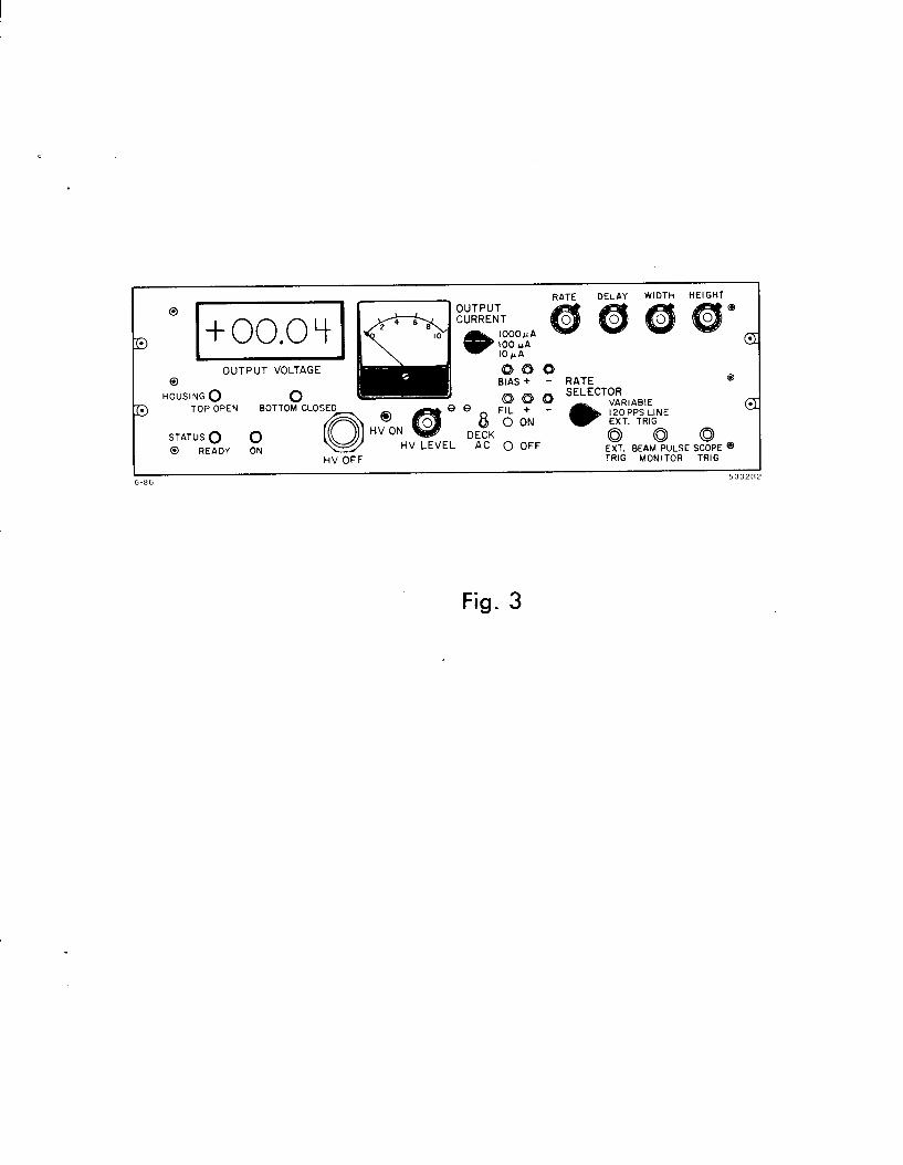
shows the control panel for the pulsed x-ray facility.
The high voltage and gun controller (HVGC) provides power to both the
isolation transformer and the high voltage power supply. It utilizes the feedback
signal from the HV supply to display the high voltage on the x-ray tube digitally,
and the x-ray tube current on an analog meter. It is also possible to set the pulse
parameters and high voltage level from this unit. The power to the high voltage
power supply (HVPS) is interlocked to the doors of the cabinet. The cabinet has
three pairs of doors which can only be closed in sequence starting from the top.
The gun will not operate if any of the doors are open. A lead lined sheet with an
opening can be installed instead of one door and still maintain the integrity of
the interlock chain. The opening permits the operator to test radiation detection
instruments with remote read out systems.
Light emitting diodes (LED’s) f o various colors indicate the status of the
doors and the high voltage. The functions of the various LED’s are described
below.
t Spellman, High-Voltage Electronics Corp., 1930 Adee Ave., Bronx, N. Y. 10469.
4

TOP OPEN. This means that any or all of the two pairs of top doors are open.
. BOTTOM CLOSED. This shows that the bottom doors are closed thereby indi-
cating that all doors are closed.
STATUS READY. This indicates that the system is ready for operation.
STATUS ON. This means that the HV is on. The HV can be controlled by the
“HV ON” or “HV OFF” switches.
The function of the various dials are listed below.
HV LEVEL. This sets the amount of voltage to be sent to the cathode, and can
be varied from 0 to 100 kilovolts (kV).
RATE. This controls the rate at which the x-rays are being pulsed. The rate
selector has three settings. The variable setting offers a range of rates from 36 to
360 Hz. The 120 pps line provides a pulse that is synchronized with the incoming
ac signal. The external trigger (EXT TRIG) setting can be used when one desires
to use a range of rates provided by an external pulse generator. A pulse generator
can be connected to the output marked “EXT TRIG”.
DELAY. This will hold the pulse (that eventually pulses the cathode) from 200
nanoseconds (ns) to 2 microseconds (ps) b e ore sending it to the gun. This delay f
makes it possible to trigger equipment to synchronize with the gun pulse instead
of the generated pulse. The “SCOPE TRIG” output can be used to trigger the
oscilloscope. The “Beam Pulse Monitor” is a monitor point for the pulse going
into the HV card cage.
WIDTH. This controls the width of the pulse measured in time, and can be varied
from 360 ns to 5 ps.
HEIGHT. This varies the voltage that is sent to the bias supply in the HV card
cage. The bias voltage can be varied from 50 to 250 volts.
5
OUTPUT CURRENT. This measures the current produced by the HV stack
going to the gun. This is monitored by an ammeter that has three range settings,
1000 uA, 100 uA and 10 uA.
OUTPUT VOLTAGE. A digital voltmeter monitors the voltage sent to the HV.
DECK AC. This turns on the isolation transformer. The two LED’s labelled
“ON” and “OFF” indicate the corresponding status of the deck ac power.
FIL AND BIAS SETTINGS. The filament setting (FIL) sends information to
the fiber optic cards in the card cage regarding the filament voltage. The bias
(BIAS) setting sends information to the cards regarding the bias voltage.
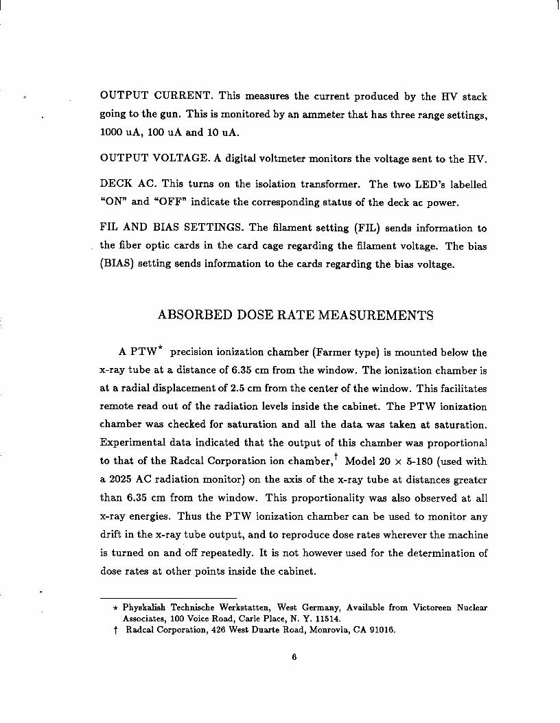
ABSORBED DOSE RATE MEASUREMENTS
A PTW* precision ionization chamber (Farmer type) is mounted below the
x-ray tube at a distance of 6.35 cm from the window. The ionization chamber is
at a radial displacement of 2.5 cm from the center of the window. This facilitates
remote read out of the radiation levels inside the cabinet. The PTW ionization
chamber was checked for saturation and all the data was taken at saturation.
Experimental data indicated that the output of this chamber was proportional
to that of the Radcal Corporation ion chamber,+ Model 20 x 5-180 (used with
a 2025 AC radiation monitor) on the axis of the x-ray tube at distances greater
than 6.35 cm from the window. This proportionality was also observed at all
x-ray energies. Thus the PTW ionization chamber can be used to monitor any
drift in the x-ray tube output, and to reproduce dose rates wherever the machine
is turned on and off repeatedly. It is not however used for the determination of
dose rates at other points inside the cabinet.
* Physkalish Technische Werkstatten, West Germany, Available from Victoreen Nuclear Associates, 100 Voice Road, Carle Place, N. Y. 11514.
t Radcal Corporation, 426 West Duarte Road, Monrovia, CA 91016.
6
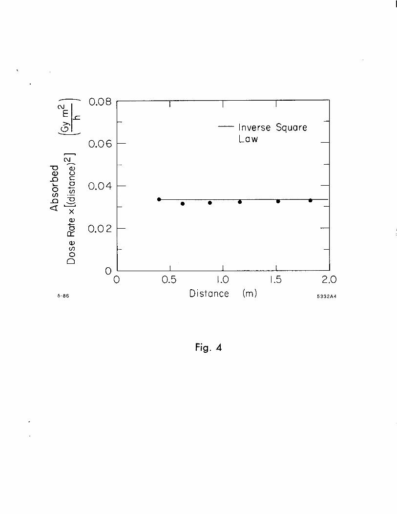
Measurements taken with a Radcal Corporation ion chamber, Model 20 x
5-180 (used with a 2025 AC radiation monitor) indicate that the pulsed x-rays
follow an inverse square law rather closely within the cabinet, as seen in Figure 4.
Dose rate measurements were made with lithium fluoride thermoluminescent
dosimeters (TLD) in the form of discs at 21 points distributed within the area
of a circle of diameter 50 cm on the floor of the cabinet. The measured dose
rate was found to be constant with a standard deviation of 10%. No particular
pattern of distribution was evident in the low and high readings of the TLD’s.
The particular batch of TLD’s that was used never showed a standard deviation
of less than 6%. Thus the dose rate is believed to be uniform over this area. At
these energies there is not much variation of x-ray intensity with angle. Hence
it has been our intention to make dose rate measurements only within this area.
However measurements were made out to the walls of the cabinet with the Radcal
ionization chamber. Since the chamber is about 12 cm in diameter it was possible
to make dose rate measurements out to a distance of 52 cm from the x-ray tube
axis to the center of the chamber. The dose rate at 52 cm decreased by about
11% from that at the center for a pulse of width 2 ps and frequency 120 Hz at
70 kV. However it must be pointed out that about 7% of this change can be
attributed to the inverse square law effect.
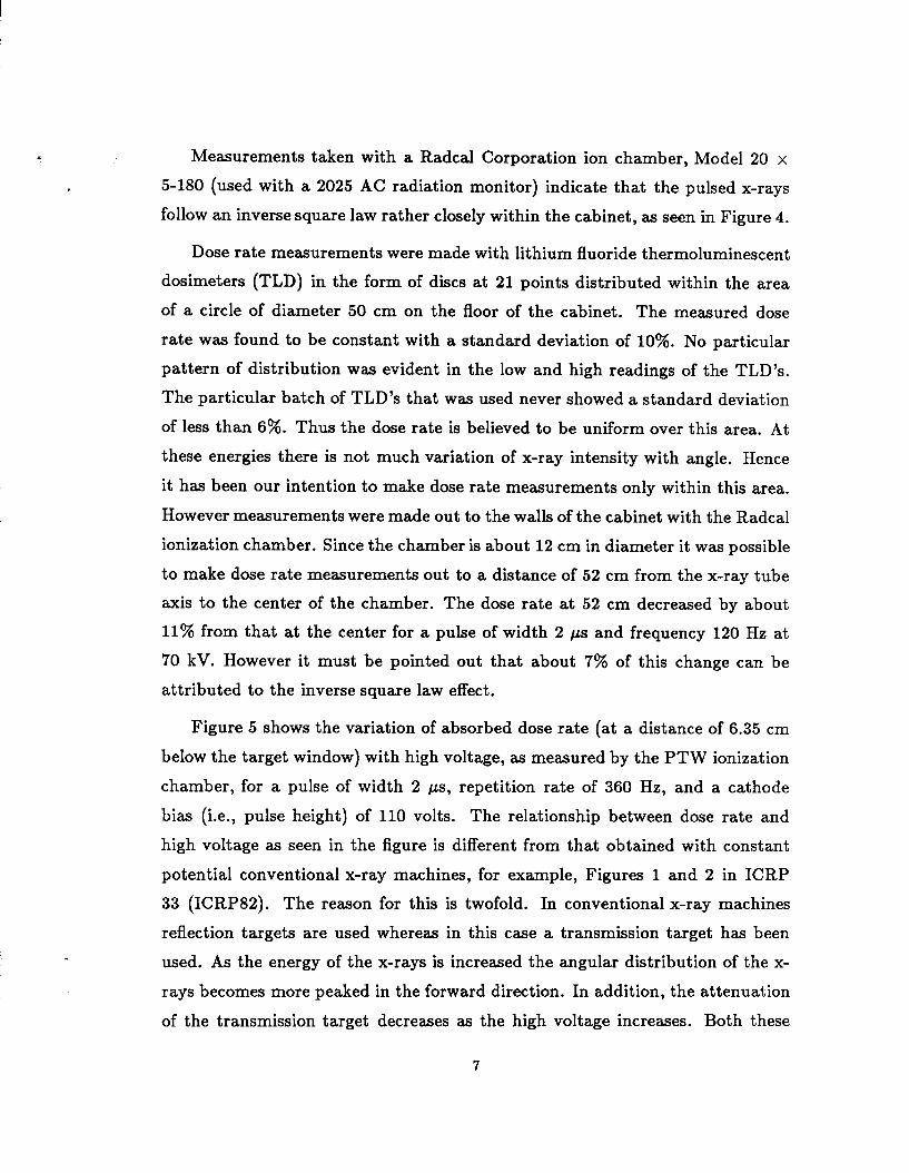
Figure 5 shows the variation of absorbed dose rate (at a distance of 6.35 cm
below the target window) with high voltage, as measured by the PTW ionization
chamber, for a pulse of width 2 /.Js, repetition rate of 360 Hz, and a cathode
bias (i.e., pulse height) of 110 volts. The relationship between dose rate and
high voltage as seen in the figure is different from that obtained with constant
potential conventional x-ray machines, for example, Figures 1 and 2 in ICRP
33 (1~~~82). Th e reason for this is twofold. In conventional x-ray machines
reflection targets are used whereas in this case a transmission target has been
used. As the energy of the x-rays is increased the angular distribution of the x-
rays becomes more peaked in the forward direction. In addition, the attenuation
of the transmission target decreases as the high voltage increases. Both these
7

effects produce a greater dose rate increase with high voltage than shown in the
reference above.
For a given high voltage the maximum dose rate obtained depends upon the
pulse width, pulse repetition rate and the pulse height. The measurements taken
indicate that the dose rate varies linearly with pulse widths ranging from 1 ps to 5 ps. The dose rate is also linearly dependent upon the pulse repetition rates
between 60 Hz and 360 Hz.
Table 1 shows the maximum dose rates obtained at different energies for
a pulse of given width, height and repetition rate. The maximum dose rate
obtained is limited by breakdown of the vacuum. The maximum dose rate at
6.35 cm. below the target window as measured by the PTW ionization chamber
is 258 gray/hour (Gy/h). Under th ese operating conditions the radiation field
to which the operator is exposed does not exceed 10 pGy/h (1 mrad/h). The
reproducibility of the x-ray tube is excellent, dose rates being easily reproduced
within 1%.
CONCLUSIONS
The pulsed x-ray facility has been very useful in testing the response of dif-
ferent radiation detection instruments, both commercial as well as those built
at SLAC, to pulsed radiation fields. The facility has proved to be very versatile
offering pulsed dose rates as high as 258 Gy/h (at a distance of 6.35 cm from
the target), pulse widths varying from 360 ns to 5 ps and pulse repetition rates
varying from 60 Hz to 360 Hz.
ACKNOWLEDGMENTS
The authors would like to thank Ron Koontz of SLAC and his associates for
designing and building the pulsed x-ray facility.
REFERENCES
IAEA79 International Atomic Energy Agency, 1979, Radiological Safety Aspects
of the Operation of Electron Linear Accelerators, STI/DOC/188 (written by
W. P. Swanson) (Vienna:IAEA) .
Pa73 Patterson H. W. and Thomas R. H., 1973, uAccelerator Health Physics,”
(New York: Academic Press).
ICRP82 International Commission on Radiological Protection, 1982, “Protec-
tion Against Ionizing Radiation from External Sources Used in Medicine,”
ICRP Publication 98 (Oxford: Pergamon Press).

TABLE 1
Voltage (kV) Dose Rate (Gy/h)
100 258 90 225 80 192 70 175 60 125 50 72.9 40 25.8 30 6.46 20 3.90
10

TABLE CAPTION
Table 1. Maximum dose rates obtained on axis at different high voltages at a
distance of 6.35 cm from the target for a pulse of width 2 ps and frequency
360 Hz.
FIGURE CAPTIONS
Figure 1. A partially cut-away view of the SLAC pulsed x-ray facility.
Figure 2. Block diagram of the pulsed x-ray electronics.
Figure 3. Control panel for the pulsed x-ray facility.
Figure 4. Absorbed dose rates measured on axis as a function of distance from
the x-ray target for a pulse of width 1 ps and frequency of 360 Hz at 80 kV.
Figure 5. Absorbed dose rates measured on axis as a function of high voltage for
a pulse of width 2 ps and frequency 360 Hz.
11

Gun
tage
- Ion Pump
-Target
-Cabinet
-PTW Ion Chamber
Fig. 1

1 Mounted on Top of Chamber
Terminal High-Voltage Block Card Cage
Incoming High Voltage f-100 kV)
Isolation Transformer
--___/I____
Mounted in Rack
5-66
i
Te;;pka I
=iber Optic Control Cable
1 \ I C ‘) II
c 2 Gun High-Voltage
Stack c 3 (voltage multiplier)
__--- --
High-Voltage . Driver
(-5kV)
5-Wire Cable
_ High-Voltage Gun Controller
Incoming f A.C. Power Door Interlock
5332A3
Fig. 2
OUTPUT VOLTAGE
STATUS 0 0
0 READY O N I-IV OFF
Fig. 3
5-86
0.08 I
- Inverse Square 0.06 Law -
0.04 - 0 0 0 l l I
0.02 -
0 I I I
0 0.5 1.0 1.5 2.0 Distance Cm> 5332A4
Fig. 4

5332A5
IO3
IO2
IO I
IO0
16’
I I I I I I
Cathode B ias=-110 V l at 6.35cm from Target
-
-
0 30 60 90 HIGH VOLTAGE (kV) 5.86
Fig. 5