the simian architecture - an object-orientated framework for
TRANSCRIPT
148
THE SIMIAN ARCHITECTURE - AN OBJECT-ORIENTATED FRAMEWORK FOR INTEGRATED POWER SYSTEM MODELLING, ANALYSIS AND CONTROL
N.B.P. Phillips, J.O. Gann and M.R. Irving
Brunel Institute of Power Systems, Brunel University, UK
ABSTRACT
This paper details the work conducted by the Brunel Institute of Power Systems into an Object Orientated framework for Power Systems Modelling, Analysis and Control.
Based around a central OODBMS (Object Orientated Database Management System), the architecture provides a framework for the construction of analysis and control applications and the sharing of calculated or real-time data between the applications. Although the paper details the architecture only in so far as its applicability to two applications, the framework is designed such that further applications, either client output (such as Control applications) or input (such as SCADA systems) may easily be added to the basic structure.
To illustrate the architecture, a loadflow simulation application is presented, along with the strategy for incorporating other applications. The mechanism by which these ‘applications’ interact with the OODBMS and core structure of the architecture is illustrated.
INTRODUCTION
Over the last few years it has become increasingly ap- parent that power system computer solutions currently in-place are becoming inadequate. Todays business re- quirements demand complex data models, fast access and information sharing across the whole of the busi- ness. Object orientated software languages, databases and development techniques are now seen as a ossible solution to this problem and much r e~ea rch [~>~’ ,**I has been devoted to the application of this methodology to power system analysis and control.
.p
The SIMIAN System Architecture
The SIMIAN architecture (SIMulation Image and ANi- mation) is an object-orientated framework designed spe- cifically to enable the sharing of data between different business processes within a complex data environment.
The SIMIAN architecture consists of 5 major compo- nents.
0 A central OODBMS.
0 A general architecture class heirachy,
0 An application specific class heirachy derived from the general classes,
An inter-application communication protocol and Event Handler,
A number of ‘applications’
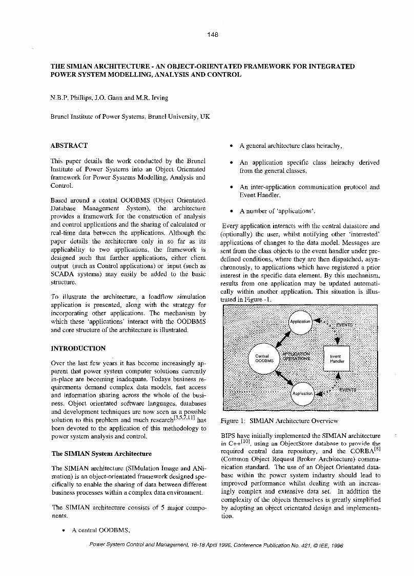
Every application interacts with the central datastore and (optionally) the user, whilst notifying other ‘interested’ applications of changes to the data model. Messages are sent from the class objects to the event handler under pre- defined conditions, where they are then dispatched, asyn- chronously, to applications which have registered a prior interest in the specific data element. By this mechanism, results from one application may be updated automati- cally within another application. This situation is illus- trated in Figure - 1.
Figure 1 : SIMIAN Architecture Overview
BIPS have initially implemented the SIMIAN architecture in C++[’ol, using an Objectstore database to provide the required central data repository, and the CORBAL8I (Common Object Request Broker Architecture) commu- nication standard. The use of an Object Orientated data- base within the power system industry should lead to improved performance whilst dealing with an increas- ingly complex and extensive data set. In addition the complexity of the objects themselves is greatly simplified by adopting an object orientated design and implementa- tion.
Power System Control and Management, 16-18Aprill996, Conference Publication No. 421, 0 IEE, 1996

149
Overview of SIMIAN Class Heirachy
The top of the SIMIAN class heirachy defines basic functionality common to all Objects within the system. Each layer is defined to perform a specific function (Figure-2)
Figure 2: Overview of the SIMIAN class heirachy
The abstract superclass, dynamic behaviour and mes- saging class groups form the core classes of the archi- tecture, irrespective of application. The further class groups are application dependent. Figure-2 only depicts a network topology and model class heirachy, though in other applications, such as required for integrating a SCADA system into the architecture, the classes of that hierarchy would be placed in the parallel hierarchy posi- tion within the diagram.
The following sections detail the implementation of the component parts of the SIMIAN architecture and the implications for applications and algorithms.
THE SIMIAN ARCHITECTURE BASE CLASSES
Figure-3 depicts, following OMTt9] notation, the class heirachy for the SIMIAN base class heirachy, incorporating the dynamic behaviour and messaging layers of the SIMIAN class heirachy.
Figure 3: SIMIAN Core Class Heirachy
The Dynamic Behaviour of Objects
One of the prime tenets of the SIMIAN architecture is the flexibility and extensibility that the system should provide, enabling levels of customisation at run-time. Although a software producer may endeavour to pro- vide facilities for most users, there will always be func- tionality that is not covered. Some flexibility is also de- manded if the system is to enable easy extension over time (independent of any database schema migration functionality).
During the design phase of an object-orientated applica- tion the behaviour of an object is frequently established by defining logical state machines for the proposed classes within a ~ y s t e m [ ~ ’ ~ ’ ~ ] . The valid states for a class are then translated into program code to create the inter- nal data members and external constraints for the class.
The design of the SIMIAN classes also follows this principle, but rather than translate the state machine model into static, programmatic statements, demands that each Object within the system be associated with an explicit state machine.
Declaring the behaviour of the object within an explicit state machine provides a number of benefits over the traditional mechanism of programmatic statements.
Encapsulation of explicit object behaviour in one class
The behaviour of objects, though linked to class inheritance is not fixed to it, relievin the difficulties associated with state and inheritance B1 .
State Machine are modifiable at run-time
User may query the state of an object
User may alter the behaviour of an object
User may associate / disassociate actions with a change in state of the Object
State changes may be dynamically triggered through a single user interface
The behaviour of an object may be relayed to the user through a single mechanism rather than a diverse set of attributes (thus simplifying user interface design).
The internal state machine of each object provides a dynamic behaviour model for the object. From Figure-3, Each state machine may be based upon a parent state machine. Run-time editing may be either performed by creating a child machine (in an analogous manner to class inheritance) - involving a change to only the behaviour of the class instance, or alternatively to the associated state machine, altering the behaviour of all

150
class objects associated with the given machine as well as all its children.
Each state machine contains a set of internal states, a set of external triggers and a set of transitions. Once all the input states for a transition are VALID, the transformation to the output states is instigated. If the transition completes (see below) a message is sent to the Event Handler application to notify interested applications of a possible change in data for the class instance.
Dynamic Functions. Each transition may be associated with a number of instances of the class saDynamicFunc- tion. Instances of the class SaDynamicFunction serve as synchronous messages demanding the execution of a class member function (of any class inherited from the abstract base class) defined for the owning object. These messages may either be processed prior to (as a pre- requisite for the transitions execution) or after the suc- cessful completion of the transition (as a side effect of the transition).
State Variables. Dynamic Functions allow different be- haviour to be exhibited each time the state of an object changes. In corollary, State Variables allow for a class member variable to exhibit a different value depending upon the state of the machine.
For instance, the power rating for overhead lines and underground cables is dependent upon the temperature of the surrounding medium (air or earth). Rather than providing 4 variables and the associated access methods within the Line / Cable class, the value can be linked to 4 states defined for the conductor - one value associated with each state.
To illustrate how the complete dynamic behaviour sub- system fits together, consider the following example.
As part of a CircuitBreaker class, there exist two states corresponding to the Open and Closed states of the de- vice. Conventional coding of the class would entail con- structing public functions to open and close the switch as well as internal data to hold the current state of the switch. Under the State Machine mechanism for deter- mining the interface to a class, the class utilises a state machine that contains the two states Open and Closed, as well as the trigger states ‘openswitch’, ‘closeSwitch’ and associated transitions, illustrated in Figure-4..
:loseSwit
Figure 4: Simple Switch toggle state Machine
This model may be adequate for a power system model- ling simulation of a switch, but is in no way adequate for a control application which requires many more safeguards to be built into the switch model. To add these constraints to the behaviour of a conventional sys- tem would require the recoding of the class. However, under the SIMIAN system, the support for control appli- cations may be simply inserted by amending the ma- chine definition to that in Figure-5.
Figure 5: Augmented Switch State Machine
In Figure-5 the changing of the state of a switch now re- quires confirmation - two additional trigger states and two extra internal states are inserted. In addition, a dy- namic function (sendMessage) is now associated with the transition from ‘Switch Open Pending’ to ‘Open’. The sendMessage function (common to all objects) dis- patches a message to the SIMIAN event handler, which would subsequently be passed to the relevant applica- tion to provide an audible signal at the control desk.
It is important to note that the incorporation of this func- tionality can be conducted during system run-time. State Machines may be edited by authorised personnel at any time, while the link between the core code and the audi- ble signal is through a message passing protocol to an independent application (which accesses the core OODBMS).
Inter-Object Communication
As described in the Introduction and mentioned in the above example, each object within the system may send messages to any other object within the system. The Ob- ject class in the Core class heirachy provides this func- tionality.
Though messages ultimately pass between two objects, all messages are routed through the Event Handler ap- plication which determines which applications require the message.
The objects within applications, during their execution cycle, register an interest in either objects or categories of message. When a message arrives at the event han- dler, a check for satisfaction of either constraint is con- ducted. If successful, the object which registered the in- terest is ‘called back’ with the contents of the incoming message.

The inter-process communication system is implemem- ted using CORBA. This mechanism supplies a greater level of functionality than the simple message process- ing required above, allowing requests for information to be served, independent of language, locality and ma- chine architecture.
THE SIMIAN ARCHITECTURE POWER SYSTEM CLASSES
Figure-6 depicts the upper part of the class heirachy for the Dower system modelling auolication classes.
Figure 6: SIMIAN Power Class Heirachy
The Object class introduced in the previous section serves as the base class for the Power System Architec- ture. The principle inheritor of the Object class, in re- spect of the power system component heirachy is the Model class. This class encapsulates topological con- nectivity between power system model components.
The SIMIAN class heirachy is based, as with other upon the topological classification of plant
items I networks. Every topological entity in the archi- tecture inherits from the model class which provides topological tracing functionality as well as interconnec- tion I disconnection methods for the inherited classes. After the Model class, the heirachy divergence occurs on the basis of the cardinality of possible inter- connections to other topological models.
As depicted in Figure-6, Models may be connected to other models through the Link class. (Every Link must be connected to exactly two Models, whilst a Model may be connected to any number of Links). Though, at the Model class level in the heirachy a model may be connected to any number of other models, the exact number of models that any instance can be connected to is controlled through the execution of virtual functions in the inheritor classes. At the next level down, A Group has zero possible connections, a Port - one, a Pipe - two and a Web has n possible interconnections to other ob- jects. Further restrictions may be introduced in child classes to prohibit the interconnection of specific plant (such as plant items operating at diverse voltage levels, e.g. 132 kV directly to 415 V).
In addition to interconnection, Models may be repre- sented by other Models, and may also contain other Models.
Model Aggregation. In Power System Modelling there is frequently a need for aggregating entities (either physical or abstract) together into one ‘component model’. For instance, a Bus Selector switch is logically composed of two switches, but in fact is a single ‘com- ponent’, (the duality is also seen between Transformers and Windings and a distribution network and the substa- tions within it.).
Model Representation. Although the primary model of the network would concentrate on components, once analysis techniques (such as load flow or fault analyses) are applied to the plant model, the data is often trans- formed into specialised data structures for numerical al- gorithms. This process is wasteful since it dis-associates the physical model from the analytical model. More so since, (for example), the topology of a load flow node- branch network is fundamentally similar to the physical plant topology, rather represented in a different manner. The node-branch model. is thus regarded as simply a new representation of the network model. Each of the load flow node Model instances is composed of, through the Model Aggregation association, physical plant in the network. Moreover, the interconnectivity between the new load flow node and surrounding nodes is not reconstructed, the connectivity established be- tween the physical plant at the borders of the individual node-branch model is used instead.

152
This is illustrated in Figure-7. ARCHITECTURE APPLICATION - LOAD FLOW
Figure 7: Model Representation Schema
Model Accuracy. Each model is associated with an ac- curacy. Since, through the aggregation association, there may be many views of an area of network, the accuracy determines the extent to which any algorithm should delve before retrieving a representation of the physical plant. For instance, an algorithm may require a number of line I cable segments in series or an abstract line whose parameters are an amalgam from the individual sections. The accuracy to which the analysis must be performed dictates which representation is valid.
This concept has two by-products:
It becomes possible to conduct analyses with user defined accuracies. In regions where computational accuracy is paramount the most detailed models may be used, and conversely in unimportant regions - raising computational performance at little cost in accuracy.
If little or inaccurate detail is known for a plant item, the model is explicitly flagged as inaccurate allow- ing analysis modules to, for instance, lower the ac- curacy as a whole and inform the user of expected study accuracy - leading to more accurate user ap- praisal of the results of the analysis.
Plant Model Heirachy classes
Below the Model and connectivity constraint classes may be found the component classes. Most classes oc- cupy a position consistent with the definition of Ports, Pipes and Webs. Transformers are not a subclass of pipe since the topological connectivity is actually due to the windings - the transformer being a composite (‘Web’) subclass. Note also that analysis and network abstract objects are intermixed in the heirachy with physical plant models, in contrast to[*’. For example, the load flow Node and Branch classes alongside the Busbar and Line classes.
The IEEE 30-Bus network was used to test the applica- bility of the SIMIAN architecture.
The execution of a load flow analysis on a given electri- cal network calculates the voltage at certain points within the network, and by derivation the power flows within the network. A request for any of this informa- tion requires the execution of the analysis.
Once a request is received from the user, if no loadflow representation is associated with the model, the follow- ing sequence of events occurs:
The model establishes, through its representations and surrounding connectivity, whether it may per- form a loadflow. If not, the request is passed to any composite model above it. This process continues, recursively until a model is found that, at the mini- mum, represents a single island with load and gen- eration.
The satisfying model then constructs, from the ag- gregate components - a new loadflow network repre- sentation composed of load flow nodes I branches associated to the relevant power system components.
The loadflow network model then queries its com- ponents (which in turn query the real plant) to con- struct a Jacobian model for a Newton-Raphson load flow simulation, and the simulation is executed.
On completion, the results propagate back through to the model representations, updating the individual node I branch elements and in turn the physical plant models and links - thus satisfying the users request.
This process is unnecessary if a loadflow representation of the network already exists. When network parameters change, the tight binding between the physical and ana- lytical model allows lazy re-evaluation of the analysis. For instance, a change to the network topology invali- dates only those load flow nodes I branches directly linked to the new topology - it is not necessary to recal- culate the whole node-branch topology. Likewise a change to the parameters, say a Line WX value, does not require any topology recalculation.
A change to the required accuracy of either the analysis or the composed models may or may not require load flow topology readjustment. For high accuracy, each sequence of one or more series line elements is con- verted to a branch. With low accuracy and a low line impedance, the load flow nodes at either end are amal- gamated (the line is approximated as a perfect conduc- tor) and analysis performance is enhanced.
Results, from the Load flow simulation, on the basis of accuracy and performance were found to be encourag- ing. Though the initial construction of the load flow net- work representation was slower than a conventional FORTRAN numerical analysis, an ongoing cycle of

153
analyse-amend-reanalyse performed on a par with the equivalent sequence of conventional steps. Since this scenario is commonplace during network planning and analysis, the overall business process should be no less efficient than at present.
ACKNOWLEDGEMENT
The work presented in this paper is supported by the En- gineering and Physical Sciences Research Council (EP- SRC) at Brunel University.
The effect of the OODBMS, in comparison to a relational database storage system was more apparent. Preliminary performance evaluation of selected opera- tions between the two storage mechanisms indicate that the OODBMS performed between 36% and 173% faster than the equivalent relational model.
The performance of the SIMIAN dynamic behaviour mechanism was also assessed, and, as expected, was slower then the equivalent hard-coded C++. However, the flexibility the mechanism allowed was perceived to more than outway the slight performance degradation. In any case, continuing advances in CPU speed make sheer algorithm performance less of an issue in com- parison to 'a friendly program suite'.
The use of Model accuracy was also investigated. The effects of a single inaccuracy in a network were ob- served to have a complex interrelationship with the overall accuracy of the network study allowing only a subjective expression of the accuracy to be relayed.
Where multiple models were implemented to represent groups of plant items, the varying accuracy levels did ensure that performance was increased when an overall lower accuracy was required.
CONCLUSIONS
From the preliminary results, the SIMIAN architecture appears to be a workable and efficient system for power system modelling. Future work will investigate the ef- fects of a scaling in the size of the network. The IEEE 30-Bus network is unrealistically small compared to typical distribution planning studies of 5000 nodes.
The dynamic behaviour capability of the SIMIAN sys- tem was found to allow easy extension, whilst maintain- ing the object-orientated nature of the architecture. Inte- gration of a GUI (Graphical User Interface) both for browsing Model parameters and topological representa- tion of a network were both implemented using the dy- namic function, and state machine functionality. The use of a common mechanism not only simplified the de- sign but also enabled the resultant GUI classes to be constructed in a highly generic manner. In addition, the automatic updating of information between applications and the OODBMS was completed seamlessly through the event handling system. From this experience, it ap- pears that more complex applications, for instance SCADA, could be 'bolted-on' in a comparable manner.
REFERENCES
1. Aksit, M., Bergmans, L., 1992, "Obstacles in Object-Orientated Software Development", OOPSLA
2. Bruegge, B., Blythe, J., Jackson, J., Shufelt, J.,1992, "Object-Orientated System Modelling with OMT",
3. de Champeaux, D., Anderson, A., Feldhousen, E., 1992, "Case Study of Object-Orientated Software De- velopment", OOPSLA '92, 377 - 391.
4. Dillon, T., Chang E., 1994, "Solution of Power Sys- tem Problems through the use of the Object-Orientated Paradigm", Int. J. Electrical Power Enerw Svstems.16,
5. Foley, M., Bose, A., 1995, "Object-Orinetated On- Line Network Analysis", IEEE Transactions on Power Systems. 10, 125-132.
6. Hakavik, B., Holen, T., 1994, "Power System Mod- elling and Sparse Matrix Operations using Object- Orientated Programming", IEEE Transaction on Power Svstems, 9, 1045-1051.
7. Neyer, A., Wu, F., Imhof, K., 1990, "Object- Orientated Programming for Flexible Software: Exam- ple of a Load Flow", IEEE Transactions on Power Svs- tems, 5,689-696.
8. Object Management Group, 1991, "OMG Common Object Request Broker Architecture: Architecture and Specification", OMG TC Document 9 1.12.1
9. Rumbaugh, J., Blaha, M., Premerlani, W., Eddy, F., Lorensen W., 1991, "Object-Orientated Modelling and Design", Prentice Hall, Englewood Cliffs, NJ (USA).
10. Stroustrup, B., 1986, "The C++ Programming Lan- guage", Addison-Wesley Publishing Company Inc.
11. Tan, S., Rico-Melgoza, J., Fuerte-Esquivel, C., Acha, A., 1995, "C++ Object-Orientated Power System Software", UPEC '95 - Greenwich, 399-342.
92, 341-358.
OOPSLA '92,359-376.
157- 165.