the sas-3 power and thermal subsystems - … · sas-3 power and thermal systems to maintain power...
TRANSCRIPT
The configuration of active control devices used by SAS-3 power and thermal systems to maintain power and thermal balance is applicable to virtually any earth orbit mission without structural change. Thermal louvers keep the temperature of the control electronics between 12° and 25° C.
Introduction During the development of SAS-3, many small
astronomy experiments were being evaluated as candidates for future missions. Although their system requirements were compatible with SAS-3, they involved a wide variety of earth orbits at various inclinations and up to synchronous altitude.
An early decision was that the control section would be designed as a universal bus to control and service any or all of these missions with minimum structural and electrical change. Therefore, the control section was thermally isolated from the experiment so that it would be little affected by experiments with different power levels and thermal characteristics. A charge control system with low power dissipation was designed so that different power levels would cause only slight differences in heat dissipation in the control section. Both the solar array and charge control systems were modularized so that they could be expanded or contracted as needed. Finally, thermal control louvers were used to accommodate the necessary variations in power dissipation in the
6
control section and to reduce temperature gradients.
The SAS-3 power system was designed to supply at least 63 W of orbit average power to a spacecraft in a 300-nmi, circular, equatorial orbit with a spin axis that could be positioned by the magnetic torquing system to point in any arbitrary direction. The experiment's X-ray sensors could scan the sky one revolution per orbit (rpo) at a very slow rate and sometimes stop to examine a particular star of interest. Stopping (remaining fixed in inertial space) was a particular problem to both the power and thermal systems because it meant that the sun could remain fixed at any arbitrary orientation to the spacecraft for long periods of time. This led to the need for an omnidirectional solar array and to the requirement for the thermal louvers.
In an attempt to increase the lifetime of the temperature-sensitive battery and redundant tape recorders, their temperatures were maintained at between 12° and 25°C. Since the nonredundant battery was identified as a short-lifetime item, the power system was designed to operate without it.
APL Technical Digest
by R. M. Sullivan A. F. Hogrefe P. T. Brenza
This successful "solar-only" operation will doubtless increase mission lifetime, but at the cost of increasing the complexity and weight of the charge control. This report describes the power and thermal systems and their capabilities.
Power System
Solar Array
Most of the surface area of the control section was needed for attitude determination instruments and thermal control, leaving scant room for solar cells. Therefore, as on many other satellites, deployable solar panels were used to achieve an omnidirectional array. But for SAS-3, opposite ( coaxial) solar panels had to be coplanar to reduce disturbances in the spacecraft's attitude caused by unequal aerodynamic forces acting on opposite panels. Such a configuration is not omnidirectional. Consider four solar panels arranged in two coplanar sets. No matter how the planes are arranged, they will always intersect in a line. When the sun is on either end of the line, the output of the solar array will be zero. When the sun is near such a position, this condition would severely limit
Volume 14, Number 3
an experimenter who wishes to remain fixed in inertial space to examine an interesting source.
The problem was solved by using rotatable solar panels so that the line of intersection between their two planes can always be turned by ground command to point away from the sun. This approach has the added advantage of increasing the minimum available power to the extent that the weight of the motor drive system is more than compensated for by the decrease in required array size.
Although a large number of array configurations is possible with rotatable solar panels, three satisfy all mission requirements. Figure 1 shows one configuration with two sets of coplanar panels in the horizontal and two others in the vertical position. The other two configurations have either four horizontal or four vertical sets of panels. Figure 1 a also defines the sun angle ('Ii') as the angle between the spacecraft's +Z axis and a line between the spacecraft and the sun.
The average array current and power are shown in Fig. 2 for each configuration. The minimum power available is 63 W (at 'Ii' = 90° ). Operation of one array at lower power levels is prevented by
7

Experiment section
Solar panel (vertical position)
01 I Solar panel
(horizontal position)
Side view
Control section
-=--.x
t y
Fig. 1-SAS·3 solar array configuration.
!'I. ___ --4 panels horizontal
20 40 60 80 100 120 140 160 1/1, angle between +Z axis and sun-line (0)
140i £!
120 ~i C!)-
100 =:E :e~
80 0 ~ S~ laC!)
60 .§ ~ ~c.
40 a ~
20
Fig. 2-Average array current and power available for three solar array configurations.
8
rotating the arrays to a more favorable configuration. The area of uncertainty in the predicted current results in part from imperfect solar cell calibration, but mostly from variations in the array current caused by earth albedo (reflected sunlight). The variations occur because the spacecraft can have many view factors toward the earth for any given angle of v.
Obviously the solar panels need not be turned often. All four would be vertical for sun angles between 55 0 and 125 0
• Outside this range, most mission requirements can be met by turning only two panels to the horizontal position. Using only these two configurations, relatively constant average power is achieved (65 to 85 W). However, all four panels can be turned to the horizontal position if extra power is needed when the sun is near the Z axis. For instance, the SAS-3 experimenter needs increasing amounts of heater power at sun angles above 125 0 due to the decreasing solar incidence on the experiment at those angles.
Each of the 12 solar panel segments has a circuit of cells on both sides. Since each circuit consists of 456 cells (two groups of four in parallel by 57 in series), there are 10,944 2 X 2-cm cells on the entire spacecraft. The two groups of cells comprising each circuit are wired to produce opposite and nearly equal magnetic fields when they are illuminated. This self-cancellation of magnetic fields is done to limit disturbing torques on the spacecraft resulting from interactions with the earth's magnetic field.
Battery Operation
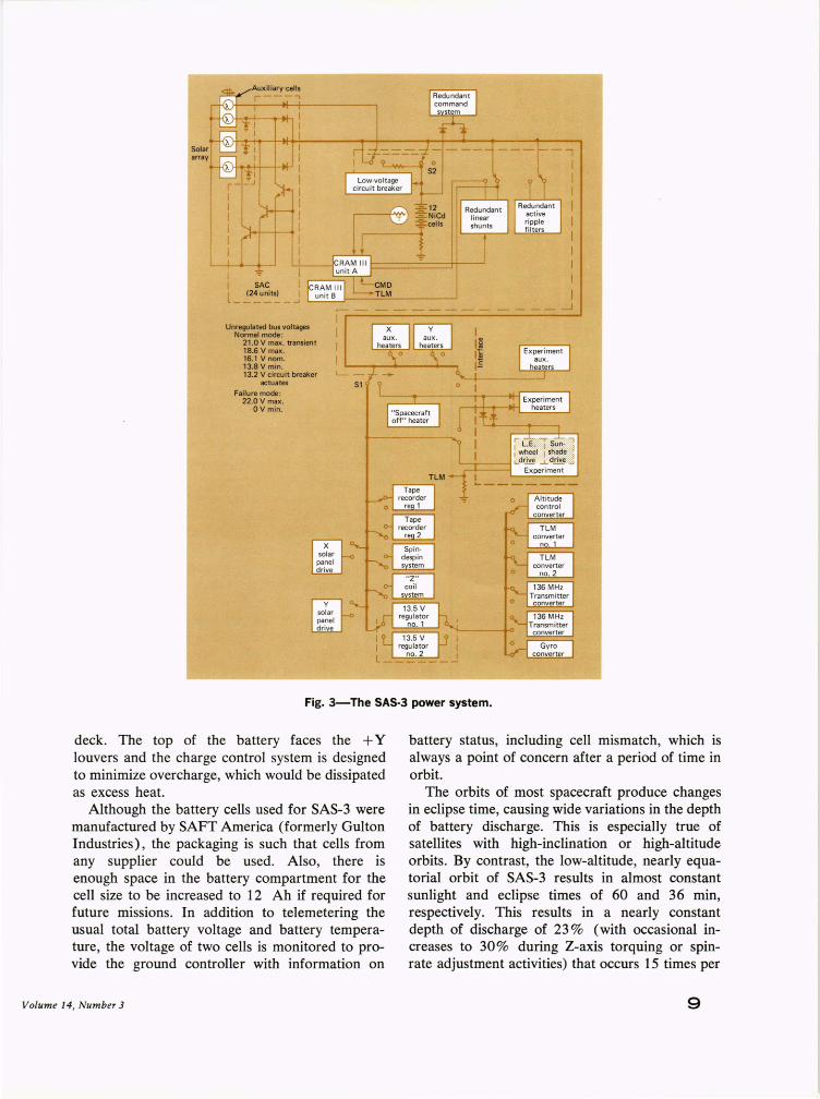
A block diagram of the SAS-3 power subsystem is shown in Fig. 3. It consists of the solar cell array, a nickel-cadmium (NiCd) battery, redundant charge control systems, power conditioning devices, heaters, and solar panel drive units. There is both a regulated and an unregulated bus. The regulated 13.5-V bus (±2%) powers both transmitters as well as the telemetry and attitude systems. All other systems, including the experiment, are powered by the unregulated 16.1-V bus ( ± 15 % ). The normal load, including requirements of the experiment section, is approximately 60 W.
The battery consists of 12 9-ampere-hour (Ah) rectangular NiCd cells. Since the battery's lifetime is extended if it is kept cool, it is packaged so that the cells are in good thermal contact with the center column of the control section and the upper
APL Technical Digest
Unrl!9Jlated bus voltages Normal mode :
21.0 V max. transient 18.6 V max. 16.1 V nom. 13.8V min. 13.2 V circuit breaker L- -
actuates 51 Failure mode :
22.0 V max. OVmin.
Fig. 3-The SAS·3 power system.
deck. The top of the battery faces the + Y louvers and the charge control system is designed to minimize overcharge, which would be dissipated as excess heat.
Although the battery cells used for SAS-3 were manufactured by SAFT America (formerly Gulton Industries), the packaging is such that cells from any supplier could be used. Also, there is enough space in the battery compartment for the cell size to be increased to 12 Ah if required for future missions. In addition to telemetering the usual total battery voltage and battery temperature, the voltage of two cells is monitored to provide the ground controller with information on
Volume 14, Number 3
battery status, including cell mismatch, which is always a point of concern after a period of time in orbit.
The orbits of most spacecraft produce changes in eclipse time, causing wide variations in the depth of battery discharge. This is especially true of satellites with high-inclination or high-altitude orbits. By contrast, the low-altitude, nearly equatorial orbit of SAS-3 results in almost constant sunlight and eclipse times of 60 and 36 min, respectively. This results in a nearly constant depth of discharge of 23 % (with occasional increases to 30% during Z-axis torquing or spinrate adjustment activities) that occurs 15 times per
9
day or 5475 times per year and gives the battery a minimum expected lifetime of slightly more than one year. (A NiCd battery needs an occasional deep discharge to prolong its life.)
The charge control system is designed to minimize variations in internal power dissipation. Figure 3 shows three solar cell parallel circuits of the 24-unit solar array providing energy to the spacecraft. Eight percent additional current is provided from auxiliary cells as backup for battery trickle charge during "solar-only" operation. Each circuit connects to the main bus through isolation diodes and contributes current as long as its voltage is above the bus level. Digital control of the individual solar array circuits allows each to be shorted by transistor power switches in a sequential manner with the Solar Array Controller (SAC). Thus the excess energy is removed with a minimum of internal heat dissipation, since the voltage drop is only 1.5 V (less than 10% of the peak charge voltage of 18.6 V). Since this is approximately the same voltage developed across the isolation diodes during charge, the SAC power variation is independent of load variation. Vernier trim of the exact battery-charging current desired is obtained by using a linear shunt of about 1.5 A maximum drain (a slightly larger current than can be produced by a single solar cell circuit). This unit will trim any necessary current from 0 to 1.5 A, but at a voltage equal to the bus level. However, most of the power in the linear shunt is dissipated outside the spacecraft in a resistor mounted on the zener diode panel.
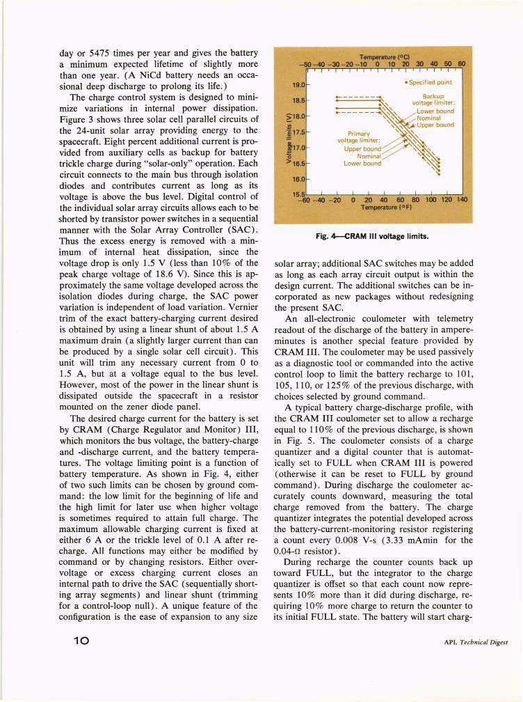
The desired charge current for the battery is set by CRAM (Charge Regulator and Monitor) III, which monitors the bus voltage, the battery-charge and -discharge current, and the battery temperatures. The voltage limiting point is a function of battery temperature. As shown in Fig. 4, either of two such limits can be chosen by ground command: the low limit for the beginning of life and the high limit for later use when higher voltage is sometimes required to attain full charge. The maximum allowable charging current is fixed at either 6 A or the trickle level of 0.1 A after recharge. All functions may either be modified by command or by changing resistors. Either overvoltage or excess charging current closes an internal path to drive the SAC (sequentially shorting array segments) and linear shunt (trimming for a control-loop null). A unique feature of the configuration is the ease of expansion to any size
10
19.0
18.5
~1 8.0
;i17.5
t 17.0 (5
>16.5
16.0
60
• Specified point
15.5'"---'---'-------'-- -'------1---'---L...---'--..I.----' -60 - 40 - 20 0 20 40 60 80 100 120 140
Temperature (O F)
Fig. 4--CRAM III voltage limits.
solar array; additional SAC switches may be added as long as each array circuit output is within the design current. The additional switches can be incorporated as new packages without redesigning the present SAC.
An all-electronic coulometer with telemetry readout of the discharge of the battery in ampereminutes is another special feature provided by CRAM III. The coulometer may be used passively as a diagnostic tool or commanded into the active control loop to limit the battery recharge to 101, 105, 110, or 125% of the previous discharge, with choices selected by ground command.
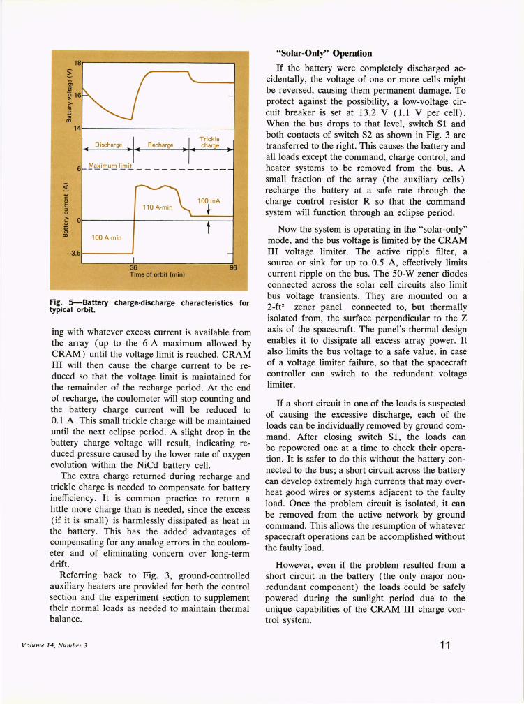
A typical battery charge-discharge profile, with the CRAM III coulometer set to allow a recharge equal to 110% of the previous discharge, is shown in Fig. 5. The coulometer consists of a charge quantizer and a digital counter that is automatically set to FULL when CRAM III is powered (otherwise it can be reset to FULL by ground command). During discharge the coulometer accurately counts downward, measuring the total charge removed from the battery. The charge quantizer integrates the potential developed across the battery-current-monitoring resistor registering a count every 0.008 V-s (3.33 mAmin for the 0.04-0 resistor).
During recharge the counter counts back up toward FULL, but the integrator to the charge quantizer is offset so that each count now represents 10% more than it did during discharge, requiring 10% more charge to return the counter to its initial FULL state. The battery will start charg-
APL Technical Digest
~
= 1'0 CD
.... c ~ ::J U
18.---------------------------~
14~--------------------------~
Discharge Recharge Trickle charge
6 ~~i~u!!!. l l!I1l1 - - - _______ _
~ O·~--------4-------------_.--~ ::: 1'0
CD 100 A-min
-3.51-------'
36 Time of orbit (min)
96
Fig. 5--Battery charge-discharge characteristics for typical orbit.
ing with whatever excess current is available from the array (up to the 6-A maximum allowed by CRAM) until the voltage limit is reached. CRAM III will then cause the charge current to be reduced so that the voltage limit is maintained for the remainder of the recharge period. At the end of recharge, the coulometer will stop counting and the battery charge current will be reduced to 0.1 A. This small trickle charge will be maintained until the next eclipse period. A slight drop in the battery charge voltage will result, indicating reduced pressure caused by the lower rate of oxygen evolution within the NiCd battery cell.
The extra charge returned during recharge and trickle charge is needed to compensate for battery inefficiency. It is common practice to return a little more charge than is needed, since the excess (if it is small) is harmlessly dissipated as heat in the battery. This has the added advantages of compensating for any analog errors in the coulometer and of eliminating concern over long-term drift.
Referring back to Fig. 3, ground-controlled auxiliary heaters are provided for both the control section and the experiment section to supplement their normal loads as needed to maintain thermal balance.
Volume 14, Number 3
"Solar-Only" Operation
If the battery were completely discharged accidentally, the voltage of one or more cells might be reversed, causing them permanent damage. To protect against the possibility, a low-voltage circuit breaker is set at 13.2 V (1.1 V per cell). When the bus drops to that level, switch S 1 and both contacts of switch S2 as shown in Fig. 3 are transferred to the right. This causes the battery and all loads except the command, charge control, and heater systems to be removed from the bus. A small fraction of the array (the auxiliary cells) recharge the battery at a safe rate through the charge control resistor R so that the command system will function through an eclipse period.
Now the system is operating in the "solar-only" mode, and the bus voltage is limited by the CRAM III voltage limiter. The active ripple filter, a source or sink for up to 0.5 A, effectively limits current ripple on the bus. The 50-W zener diodes connected across the solar cell circuits also limit bus voltage transients. They are mounted on a 2-fF zener panel connected to, but thermally isolated from, the surface perpendicular to the Z axis of the spacecraft. The panel's thermal design enables it to dissipate all excess array power. It also limits the bus voltage to a safe value, in case of a voltage limiter failure, so that the spacecraft controller can switch to the redundant voltage limiter.
If a short circuit in one of the loads is suspected of causing the excessive discharge, each of the loads can be individually removed by ground command. After closing switch SI, the loads can be repowered one at a time to check their operation. It is safer to do this without the battery connected to the bus; a short circuit across the battery can develop extremely high currents that may overheat good wires or systems adjacent to the faulty load. Once the problem circuit is isolated, it can be removed from the active network by ground command. This allows the resumption of whatever spacecraft operations can be accomplished without the faulty load.
However, even if the problem resulted from a short circuit in the battery (the only major nonredundant component) the loads could be safely powered during the sunlight period due to the unique capabilities of the CRAM III charge control system.
11
Thermal Subsystem
Thermal Design Criteria
The thermal design criteria specify three main categories of requirements for the temperature control system: temperature range, structural configuration, and thermal environment for system operation.
The temperature control ranges required for the SAS-3 are not unusual compared to those required for other satellites. They are assigned to achieve reliable, long-duration operation of the assorted electronic equipment. The temperature control ranges designated for the SAS-3 were (a) 1.7° to 32.2°C for batteries and 4.6° to 32.3 °C for tape recorders, both temperature-sensitive items; (b) -12.2° to +43.3 °C for other electronic equipment; and (c) the respective design limits for sensors located on the satellite's surface. In addition to the above requirements, several goals were established: to maintain the battery's temperatures near the lower end of its designated temperature range; to maintain the tape recorders within a range of 10° to 30°C; and to maintain the electronic equipment within the overall 1.7° to 32.2°C range for temperature-sensitive items. The operating life of electronic equipment is enhanced by stricter temperature control.
The structural configuration requirements were stringent. They included minimum weight and volume, fewest interfaces, high reliability, redundancy, and minimum use of satellite power for temperature control. A versatile system design was also required so that the system could be tailored to accommodate the special needs of future missions. Tailoring of the system was to be accomplished without making structural changes in the control section design.
Thermal Environment
Since SAS-3 was to be designed as a control section bus for many missions, its thermal environment requirements were uniquely severe among satellite designs. The temperature was to be limited to the ranges mentioned above for all combinations of the following situations:
1. Equatorial or polar orbits; 2. All orbit altitudes for equatorial or polar
missions; 3. No limitations on orientation (i.e., the satel
lite can be pointed and maintained in any position at any time in orbit);
12
4. Spinning, slowly rolling, or nonspinning satellites; and
5. A wide range of heat loads from electronic equipment.
These conditions result in an envelope for thermal environment that accommodates almost all possible earth orbit missions.
The type of orbit (equatorial or polar) dictates to some extent the amount of time during each orbit when the satellite is exposed to direct solar radiation. This exposure time, which varies during the year, is a critical factor in the thermal design of the satellite. Considering the shadowing from the experiment, the range of sunlight for the SAS-3 thermal design was 0 to 100 % .
The orbital altitude, apogee and perigee, defines the amount of energy that the satellite receives from the earth in the form of reflected solar and thermal radiation. The magnitude of these heating sources is critical to the thermal design.
The orientation (pointing direction) of the satellite in orbit determines the areas on its surface that receive radiation from the earth and sun. Obviously, unless the orientation is controlled, location on the satellite's surface can be exposed at some time during the mission to a wide range of thermal energy.
Rapid body motion influences the transient rate at which thermal energy impinges on a satellite's surface. A spinning satellite tends to average out the thermal energy over the surfaces that are parallel to the spin axis and exposed to the energy source. A satellite that is slowly rotating and not spinning focuses thermal energy on the surfaces that are in view of the energy source. Thus, thermal designs can be generated to accommodate each roll-rate characteristic by concentrating on its special thermal situation; to accommodate all spin, roll, or nonspin characteristics with one thermal design is a real challenge.
The heat loads generated by electronic equipment influence the thermal design in that effective temperature control depends upon the ability to dump greater heat loads more rapidly into space. Wide ranges of heat load require more complex regulation (thermal design).
In summary, the thermal environment for which the SAS-3 temperature control system was designed consisted of (a) maximum and minimum radiations including solar, earth-reflected solar, and earth thermal; (b) all possible distributions
APL Technical Digest
of these radiations over the surfaces of the control section; and (c) a wide range of heat loads from electronic equipment. Note that many factors are involved in calculating the magnitude of the inorbit thermal energies that will be absorbed and radiated from satellite surfaces. The most significant factor is the optical properties of the surface coatings.
Thermal Design Concept
The innovative thermal design concept for SAS-3 was to control temperature by using internal thermal louvers that regulate the rate at which the heat load from electronic equipment is transmitted to the outer surface of the control section for dumping to space. The louvers change the path of the radiation heat flow between the equipment compartment and the space radiators as a function of the equipment temperature. Here is a functional sequence of events for this concept:
1. An increase in the heat load from electronic equipment or from exposure of the control section to a hotter thermal environment causes a rise in the temperature of the bimetal actuators (springs ) of the louvers subsystem.
2. Twisting occurs because of the different expansion rates of the two metals of the springs.
3. The twisting force rotates the louver blades, attached to the springs, to a more open position and provides the equipment compartment with a greater view of the space radiator panels.
4. The greater view reduces the thermal resistance to heat flow between the compartment and the radiators.
5. With the decreased thermal resistance, the heat flow rate to the space radiators is increased, thus maintaining the desired temperature level for the equipment.
When the heat load from the equipment is reduced or the control section is exposed to a lesser thermal environment, a converse sequence of events occurs.
The thermal-louvers subsystem must have the required thermal performance characteristics and be sized appropriately so that the subsystem can be "set." (The term "set" means to adjust the system to function over a specific range of operating temperatures.) Since the subsystem's func-
Vo lume 14, Number 3
tional temperature range is based on the temperature at the bimetal actuators, the temperature difference between the actuators and the electronic equipment directly influences the range of temperature control that can be realized from the thermal design.
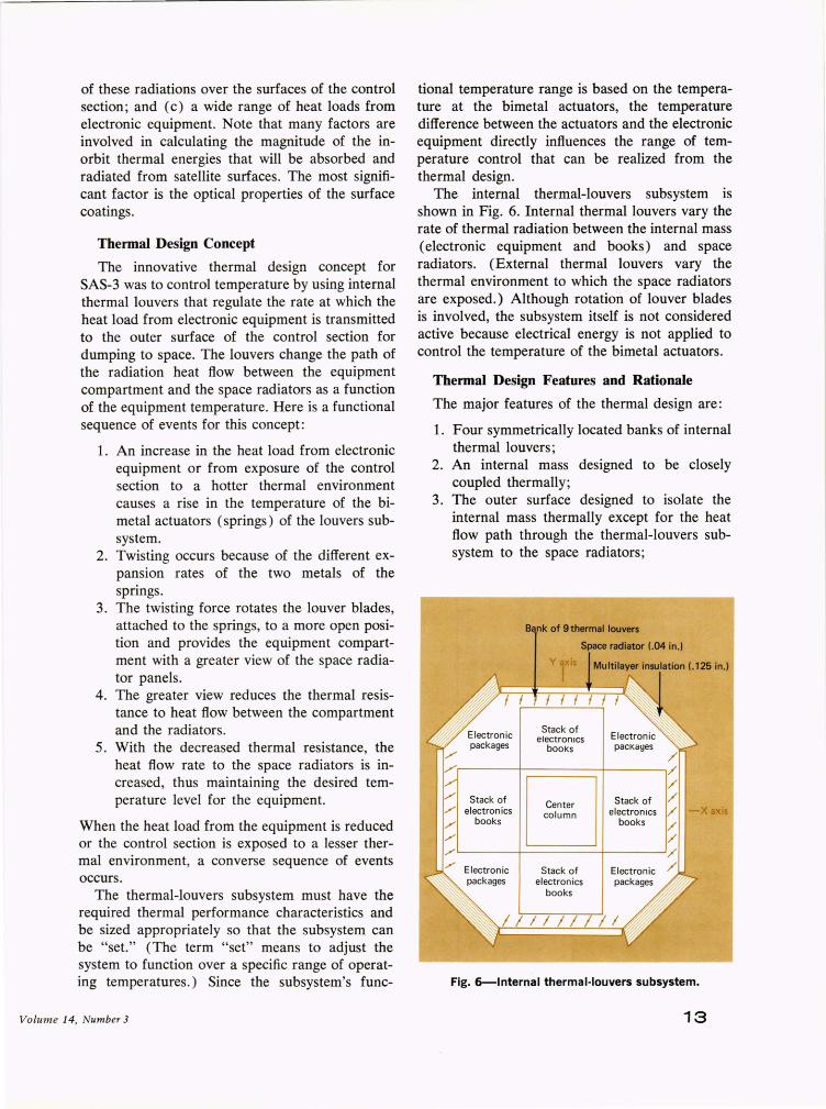
The internal thermal-louvers subsystem is shown in Fig. 6. Internal thermal louvers vary the rate of thermal radiation between the internal mass ( electronic equipment and books) and space radiators. (External thermal louvers vary the thermal environment to which the space radiators are exposed.) Although rotation of louver blades is involved, the subsystem itself is not considered active because electrical energy is not applied to control the temperature of the bimetal actuators.
Thermal Design Features and Rationale
The major features of the thermal design are:
1. Four symmetrically located banks of internal thermal louvers;
2. An internal mass designed to be closely coupled thermally;
3. The outer surface designed to isolate the internal mass thermally except for the heat flow path through the thermal-louvers subsystem to the space radiators;
./
./
./
./
./ ,;-
Bank of 9 thermal louvers
Space radiator (.04 in.)
/I Y III
Stack of electronics
books
Stack of electronics
bOO ks
Center column
Stack of electron ics
books
Stack of electronics
books
Electron ic packages
//11////1
/ / / / / / / / /
-X axis
Fig. 6-lnternal thermal·louvers subsystem.
13

4. An optimum size relationship between space radiators and thermal louvers;
5. An optimum thermal relationship between the internal mass and the space radiators; and
6. An optimum "set point" for the thermallouvers subsystem.
The first three features allow the subsystem to perform its function regardless of the direction in which the control section is pointed with respect to the thermal energy sources in orbit. To clarify this point, the surface coating on the space radiators is silver-Teflon with a solar absorptivity of about 0.09 and an emittance of 0.80. With these optical properties, all four space radiators reach a temperature that is colder for all thermal environments than the design limits for the electronic equipment. However, space radiators that are exposed to a hot environment in orbit lose their ability to dump their share of internal heat load, and the remaining' colder radiators take up the extra load.
The internal electronic equipment is designed to be closely coupled thermally so that a uniform internal-mass temperature can be achieved throughout the compartment. This approach eliminates local hot and cold spots and temperature gradients. It minimizes the problems associated with setting the thermal-louvers subsystem and allows all four radiators to contribute to dumping the total heat load even though the heat loads are scattered throughout the internal mass.
The optimum size of the radiator/ thermallouvers subsystem depends upon many factors: the desired range of temperature control; the range of temperatures affecting the control section in orbit and their distribution over the control section's surface area; the range of heat loads generated by the electronic equipment; the thermal relationships between the space radiators and the surfaces of the internal mass adjacent to the space radiators; the characteristics of surface coatings for the space radiators; unavoidable heat leaks resulting from structural and functional requirements of sensors that must be connected to the internal mass and exposed to the in-orbit thermal environment; and the performance characteristics of the thermallouvers subsystem. Without describing in detail each factor or the impact of tradeoffs between the various factors, an optimum radiator/ thermallouver subsystem resulted that has an area of 6.79 ft2 for the SAS-3 configuration with func-
14
tional areas of 1.45 fF located on the + Y side of the control section and 1.78 ft2 on the '- Y, +X, and - X sides. With these sizes, the thermal design provides temperature control within required limits for the following orbits and heat loads that include the worst possible thermal environment in each orbit:
1. Equatorial orbits-20 to 70 W; 2. Polar orbits-20 to 65 W; and 3. Synchronous orbit-31 to 80 W.
The range of satisfactory control can be extended by tailoring the thermal design to a specific mission.
Optimum control of the thermal characteristics of the internal mass was achieved by (a) providing 100 % viewing area from the equipment compartment to the space radiators (accomplished by using a high-emittance paint, Chemglaz black (e = 0.85), on the outboard surface of the electronic equipment and on the inboard surfaces of the space radiators); (b) designing the thermallouvers subsystem to close the path completely in cold environments and open it fully in hot environments; and (c) using a minimum-emittance coating of gold (e = 0.03) for the louver blades to reduce the thermal radiation coupling and thus the heat leaks through the subsystem when the louver blades are closed.
The best "set point" temperature for the louvers subsystem depends upon factors already mentioned: optimal system size, and temperature difference between the bimetal actuators and the electronic equipment. A "set point" temperature of 10c C was selected so that the batteries would tend to be within their lower design temperature range for most of the in-orbit environment while the tape recorders would not cool below their minimum design limit.
Thermal Design Techniques
Close thermal coupling of the internal mass was achieved in four ways: (a) by designing all mountings to have maximum contact area and pressure between joints; (b) by applying conductive grease between the mating surfaces at the mountings; (c) by making the center column, equipment decks, and the electronic chassis out of materials having high thermal conductivity (mainly aluminum) and of appropriate thicknesses ; and (d) by painting black all surface areas of the internal mass.
APL Technical Digest

The internal mass was thermally isolated from all heat flow paths except the thermal radiation path through the thermal-louvers subsystem by placing multilayer insulation blankets between the internal mass and the + Z and - Z sides of the control section and over all equatorial surface areas except those of the space radiators, and by blanketing as much of the attach ring as possible.
One design problem was how to reduce heat leak via the mounting stubs of the solar blades. The surface area of the control section near the stubs does not receive direct solar radiation (because of special covers) but does view deep space. Since it cannot be covered with multilayer insulation because of the rotation of solar panels, it was covered with gold tape to minimize heat leaks. On the other hand, the star sensor and the nonspinning Digital Solar Attitude Detector (DSAD) were mounted so that a minor amount of heat leak maintains them within design limits. Similarly, the reaction wheel scanner and the spinning DSAD were mounted with good thermal contact to the internal mass to supply their temperature control. Finally, fiberglass insulation joints were used to mount the space radiator panels to the internal mass to prevent conduction to the radiators.
The mounting casting for the bimetal actuators and the louver blades have a low-emittance gold coating to prevent heat leaks. The surface coating for the space radiators, as was previously mentioned, is silver-Teflon. The special paints applied to the exposed surfaces of the sensors (DSAD's) are NASA's P764-1A and leafing aluminum paints.
Summary The thermal design makes it possible to satisfy
the temperature control requirements that result from using the control section as a universal bus. For the SAS-3, the thermal design satisfies not only the design requirements but also the more ambitious, self-imposed temperature control goals. Since the thermal-louvers subsystem weighs only 3.2 lb and the remaining thermal configuration consists of multilayer insulation blankets and paints, the minimum weight criteria are realized. The thermal-louvers subsystem is inherently reliable and redundant, since it consists of 36 individually actuated and positioned louver blades; actuator failure is automatically compensated for by other actuators. The design is virtually free of mechanical interfaces, requires a small amount of
Volume 14, Number 3
control section volume, and can easily be tailored to the special needs of future missions without mechanically changing the control section configuration. The tailoring can be done by changing the surface coating on the space radiators, by changing the thermal radiation characteristics through the thermal-louvers subsystem via paints, by removing thermal louvers, and by extending the multilayer insulation blankets.
Since the design of the control section turned out to be so successful, there was little need for housekeeping data. Therefore the spacecraft's data system was turned over to performance of the scientific mission. Thus, only a limited amount of reduced flight data obtained during the early stages of the mission and data periodically reported by NASA/ GSFC during the mission's first 10 months are available.
~~----------------------------~ Temperature-sensitive items
o Battery ~30(S 0 Tape recorders
~ 8 :l 0 1ii 20 q, ~ o~ ~~Ql(IJCQ:pomP~qpo[ E 0 0 ~cR}{9 &:Aj{J:~Fo OJ OJ 0Xb &6<9 Cl1:9OJo> ~ ~ 10 O'-Q-V'-' ~
°0~~1~O'-~2~0--·3~0~-7.~~-Pro~--6~0~~70· Orbit number
Fig. 7-Flight temperature data for SAS-3 battery and tape recorders.
Figure 7 shows the history of flight temperature during the first 70 orbits for batteries and tape recorders, the items most sensitive to temperature. The thermal environments during these orbits approached worst-cold conditions. It can be seen that the thermal design goal of maintaining the tape recorders at temperatures at or above 10°C was accomplished. The periodic NASA reports have established that the temperature-sensitive items and the other electronic equipment have been maintained in the benign range of 100 to 25°C despite the varying thermal environments encountered during the mission. These have included the worst cases, hot and cold, for long enough times to establish thermal equilibrium. It can therefore be concluded that that temperature range will not be exceeded during the complete SAS-3 mission.
15