thermal power plant
TRANSCRIPT

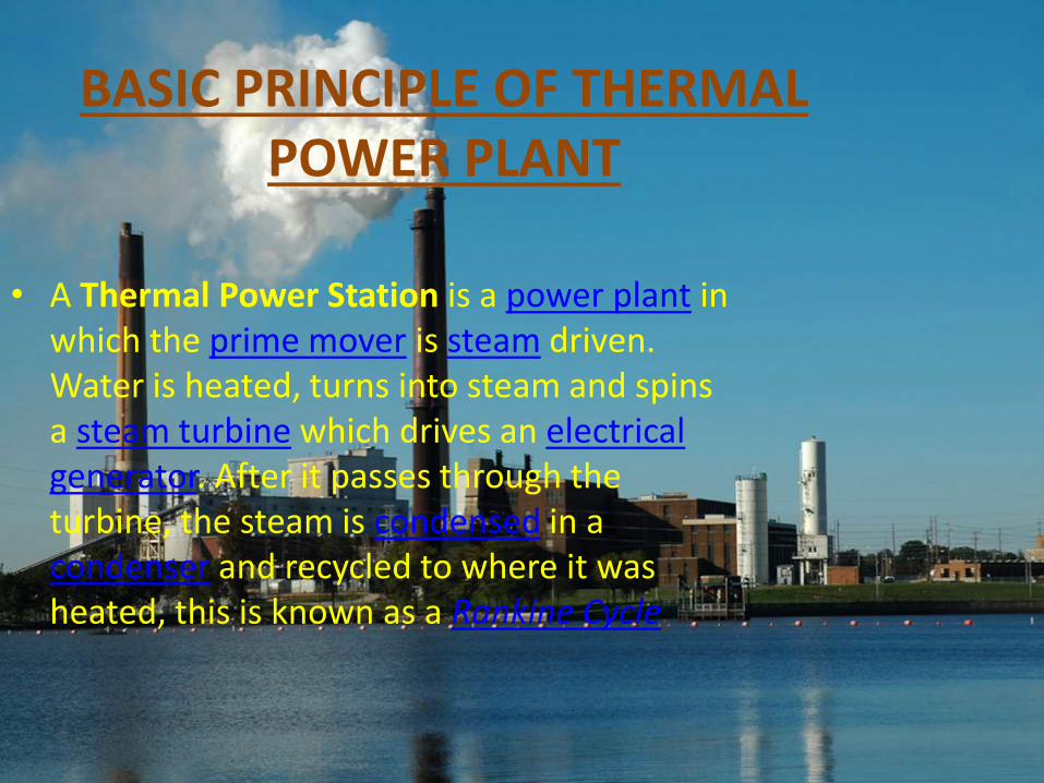
• A Thermal Power Station is a power plant in which the prime mover is steam driven. Water is heated, turns into steam and spins a steam turbine which drives an electrical generator. After it passes through the turbine, the steam is condensed in a condenser and recycled to where it was heated, this is known as a Rankine Cycle.
BASIC PRINCIPLE OF THERMAL POWER PLANT

Thermal Power Plants are modular systems which are used for decentralized generation of electricity and heat through the use of power-heat coupling. A special industrial combustion engine, designed for long-duration operation, drives the generator (electrical power) of the TPP. For the motor, a number of different fuels, both solid and liquid, can be used.
The greatest variation in the design of thermal power stations is due to the different fuel sources. Some prefer to use the term energy center because such facilities convert forms of heat energy into electricity. Some thermal power plants also deliver heat energy for industrial purposes, for district
heating , or for desalination of water as well as delivering electrical power. A large part of human CO2 emissions comes from fossil fueled thermal power plants, efforts to reduce these outputs are various and widespread.

Thermal Power Station, designed only for electricity production, is called condensation electric stations (IES). Power stations, intended for the combined production electrical energy and release steam and hot water heat consumers have a steam turbine with intermediate steam or pressure. In such installations the heat of spent steam partially or even completely used for heating, resulting in loss of heat with the cooling water is reduced.

SITE SELECTION OF THERMAL POWER PLANT
• In general, both the construction and operation of a power plant requires the existence of some conditions such as water resources and stable soil type. Still there are other criteria that although not required for the power plant, yet should be considered because they will be affected by either the construction or operation of the plants such as population centers and protected areas. The following list corers most of the factors that should be studied and considered in selection of proper sites for power plant construction:

•Transportation Network: Easy and enough access to transportation network isrequired in both power plant construction and operation periods.•Gas pipe Network: Vicinity to the gas pipes reduces the required expenses.
•Power Transmission Network: To transfer the generated electricity to theconsumers, the plant should be connected to electrical transmission system.Therefore the nearness to the electric network can play a roll.•Geology and Soil Type: The power plant should be built in an area with soil androck layers that could stand the weight and vibrations of the power plant.•Earthquake and Geological Faults: Even weak and small earthquakes can damagemany parts of a power plant intensively. Therefore the site should be away enoughfrom the faults and previous earthquake areas.

•Topography: It is proved that high elevation has a negative effect on production efficiency of gas turbines. In addition, changing of a sloping area into a flat site for the construction of the power plant needs extra budget. Therefore, the parameters of elevation and slope should be considered.•Rivers and Floodways: obviously, the power plant should have a reasonable distance from permanent and seasonal rivers and floodways.•Water Resources: For the construction and operating of power plant different volumes of water are required. This could be supplied from either rivers or underground water resources. Therefore having enough water supplies in defined vicinity can be a factor in the selection of the site.•Environmental Resources: Operation of a power plant has important impacts on environment. Therefore, priority will be given to the locations that are far enough from national parks, wildlife, protected areas, etc.•Population Centers: For the same reasons as above, the site should have an enough distance from population centers.•Need for Power: In general, the site should be near the areas that there is more need for generation capacity, to decrease the amount of power loss and transmission expenses.•Climate: Parameters such as temperature, humidity, wind direction and speed affect the productivity of a power plant and always should be taken into account.

•Land Cover: Some land cover typessuch as forests, orchard, agriculturalland, pasture are sensitive to thepollutions caused by a power plant. Theeffect of the power plant on such landcover types surrounding it should becounted for.•Area Size: Before any otherconsideration, the minimum area sizerequired for the construction of powerplant should be defined.•Distance from Airports: Usually, apower plant has high towers andchimneys and large volumes of gas.Consequently for security reasons, theyshould be away from airports.•Archeological and Historical sites:Usually historical building are fragileand at same time very valuable.Therefore the vibration caused bypower plant can damage them, and adefined distance should be considered.

Layout OF Thermal Power Plant :

Components Thermal Power Plant1. Coal handling plant2. Stoker3. Pulverizer4.Boiler5.Superheater6.Eonomiser & Air preheater7.Reheater8.Deaerator9.Condenser10.Primary air fan11.Turbine(prime mover)12.Draft fan & chimney13.Electo-static precipitator14.Cooling tower15.Ash handling plant16.Electrical equipmenta. Generatorb. Transformersc. Switch yard

Main Cycles of Thermal Power Plant
• WATER CYCLE------- CONDENSATION, FEEDPUMP, ECONOMIZER
• STEAM CYCL-------BOILER, SUPER HEATER, TURBINE
• FLUE GAS CYCLE -------ECONOMIZER, BOILER, SUPER HEATER
• CONDANSATE CYCLE-------CIRCULATING WATER PUMP, CONDENSOR, COOLING TOWER

Coal conveyor : This is a belt type ofarrangement. With this coal is transportedfrom coal storage place in power plant tothe place near by boiler.
Stoker : The coal which is brought near byboiler has to put in boiler furnace forcombustion. This stoker is a mechanicaldevice for feeding coal to a furnace.
Pulverizer : The coal is put in the boiler afterpulverization. For this pulverizer is used. Apulverizer is a device for grinding coal forcombustion in a furnace in a power plant. Apulverizer is a device for grinding coal forcombustion in a furnace in a power plant.

•Boiler : Now that pulverized coal is put in boiler furnace. Boiler is an enclosed vessel inwhich water is heated and circulated until the water is turned in to steam at the requiredpressure. Coal is burned inside the combustion chamber of boiler. The products ofcombustion are nothing but gases. These gases which are at high temperature vaporizethe water inside the boiler to steam. Some times this steam is further heated in a superheater as higher the steam pressure and temperature the greater efficiency the engine willhave in converting the heat in steam in to mechanical work. This steam at high pressureand temperature is used directly as a heating medium, or as the working fluid in a primemover to convert thermal energy to mechanical work, which in turn may be convertedto electrical energy. Although other fluids are sometimes used for these purposes, water isby far the most common because of its economy and suitable thermodynamiccharacteristics.
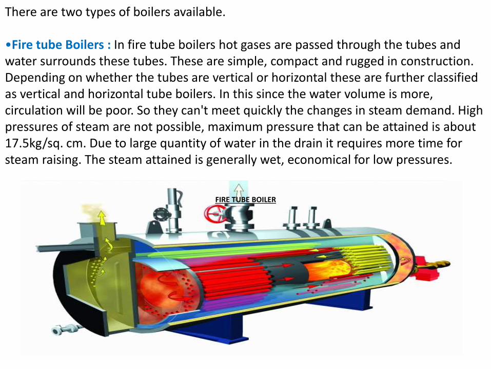
There are two types of boilers available.
•Fire tube Boilers : In fire tube boilers hot gases are passed through the tubes and water surrounds these tubes. These are simple, compact and rugged in construction. Depending on whether the tubes are vertical or horizontal these are further classified as vertical and horizontal tube boilers. In this since the water volume is more, circulation will be poor. So they can't meet quickly the changes in steam demand. High pressures of steam are not possible, maximum pressure that can be attained is about 17.5kg/sq. cm. Due to large quantity of water in the drain it requires more time for steam raising. The steam attained is generally wet, economical for low pressures.
FIRE TUBE BOILER

•Water tube Boilers : In these boilers water is inside the tubes and hot gases are outside the tubes. They consist of drums and tubes. They may contain any number of drums. Feed water enters the boiler to one drum. This water circulates through the tubes connected external to drums. Hot gases which surround these tubes will convert the water in tubes in to steam. This steam is passed through tubes and collected at the top of the drum since it is of light weight. So the drums store steam and water. The entire steam is collected in one drum and it is taken out from there. As the movement of water in the water tubes is high, so rate of heat transfer also becomes high resulting in greater efficiency. They produce high pressure, easily accessible and can respond quickly to changes in steam demand. These are also classified as vertical, horizontal and inclined tube depending on the arrangement of the tubes. These are of less weight and less liable to explosion. Large heating surfaces can be obtained by use of large number of tubes.

•Superheater : Most of the modern boilersare having super heater and reheaterarrangement. Superheater is a component ofa steam-generating unit in which steam, afterit has left the boiler drum, is heated above itssaturation temperature. The amount ofsuperheat added to the steam is influencedby the location, arrangement, and amount ofsuper heater surface installed, as well as therating of the boiler. The super heater mayconsist of one or more stages of tube banksarranged to effectively transfer heat fromthe products of combustion. Super heatersare classified as convection , radiant orcombination of these.
Reheater : Some of the heat ofsuperheated steam is used to rotate theturbine where it loses some of its energy.Reheater is also steam boiler componentin which heat is added to this intermediate-pressure steam, which has given up someof its energy in expansion through thehigh-pressure turbine. The steam afterreheating is used to rotate the secondsteam turbine where the heat is convertedto mechanical energy. This mechanicalenergy is used to run the alternator, whichis coupled to turbine , there by generating
electrical energy.
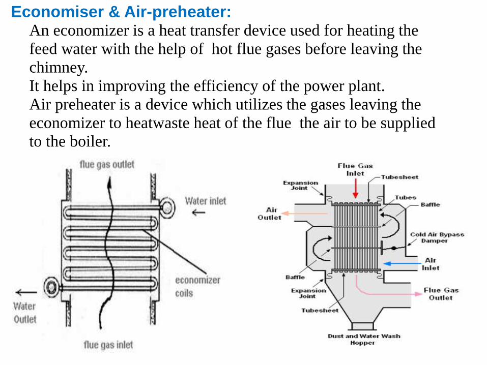
Economiser & Air-preheater:• An economizer is a heat transfer device used for heating the
feed water with the help of hot flue gases before leaving the
chimney.
• It helps in improving the efficiency of the power plant.
• Air preheater is a device which utilizes the gases leaving the
economizer to heatwaste heat of the flue the air to be supplied
to the boiler.

Turbine :•A steam turbine is a mechanical device that extracts thermal energy from pressurized
steam, and converts it into mechanical energy.
•The steam turbine is a form of heat engine that derives much of its improvement in
thermodynamic efficiency from the use of multiple stages in the expansion of the
steam, which results in a closer approach to the ideal reversible expansion process.
•About 86% of all electric generation in the world is by use of steam turbines.

Condenser:• A steam generating boiler requires that the boiler feed water should be devoid of
air and other dissolved gases, particularly corrosive ones.• In order to avoid corrosion of the metal, power station uses a Deaerator, for the
removal of air and other dissolved gases from the boiler feed water.• A deaerator has a vertical, domed deaeration section mounted on top of a
horizontal cylindrical vessel which serves as a deaerated boiler feed water storagetank.

Primary Air Fan :
•Air to blow the coal from the mill to the boiler, called the primary air, is supplied
by a large fan driven by a variable speed motor
•When mixed with a stream of air the powdered coal behaves more like a gas than
a solid
•Primary air does two jobs – heating the coal powder and secondly lifting it into
the furnace through pipelines
Induced Draught (ID) Fan
•Two induced draught fans draw gases out of the boiler
•The gas has already passed through the air heaters and precipitators before it has
reached these fans
•The heat from the flue gases or smoke is used in the air heaters to heat up the
primary and secondary air
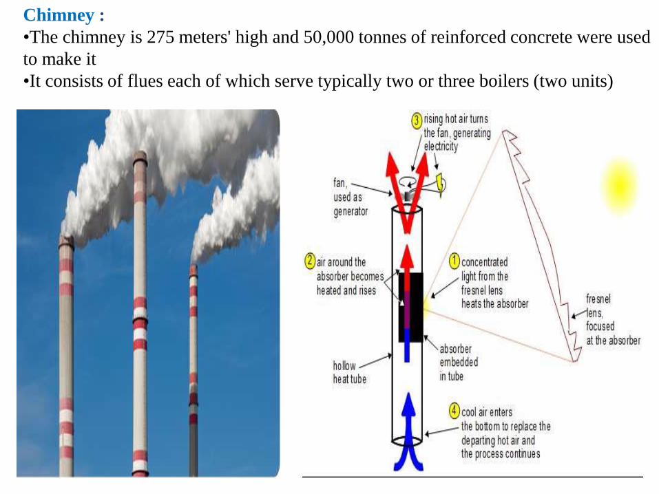
Chimney :
•The chimney is 275 meters' high and 50,000 tonnes of reinforced concrete were used
to make it
•It consists of flues each of which serve typically two or three boilers (two units)

Electro-Static Precipitator :It is a device which removes dust or other finely divided particles from flue gases by
charging the particles inductively with an electric field, then attracting them to highly
charged collector plates. Also known as precipitator. The process depends on two steps.
In the first step the suspension passes through an electric discharge (corona discharge)
area where ionization of the gas occurs. The ions produced collide with the suspended
particles and confer on them an electric charge. The charged particles drift toward an
electrode of opposite sign and are deposited on the electrode where their electric charge
is neutralized. The phenomenon would be more correctly designated as electrode
position from the gas phase
Top View of ESP Schematic
Diagram
Side view of ESP Schematic Diagram

Cooling Tower :
• Remove heat from the water discharged from
the condenser so that the water can be
discharged to the river or re circulated and
reused.
• Air can be circulated in the cooling towers
through natural draft and mechanical draft.
• Type of cooling tower1. Wet cooling tower
2. Dry cooling tower

Some other Cooling Towers :

Ash Handling Plant :
• The percentage of ash in coal is 5% in good quality coal & about 40% in poor quality coal.
• Power plants generally use poor quality of coal , thus amount of ash produced by it is quite large.
• A modern 1000MW plant produces about 4800 tons of ash daily.• The stations use some conveyor arrangement to carry ash to dump sites.

Alternator(Generator) :
An alternator is coupled to a steam turbine and converts mechanical energy of the
turbine into electrical energy.
It may be hydrogen or air cooled.
The necessary excitation is provided by means of main and pilot exciters directly
coupled to the alternator shaft.
ELECTRICAL EQUIPMENTS USED :
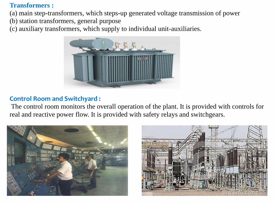
Transformers :
(a) main step-transformers, which steps-up generated voltage transmission of power
(b) station transformers, general purpose
(c) auxiliary transformers, which supply to individual unit-auxiliaries.
Control Room and Switchyard :The control room monitors the overall operation of the plant. It is provided with controls for
real and reactive power flow. It is provided with safety relays and switchgears.

Efficiency of Thermal Power Station or Plant
The overall efficiency of a thermal power station or plant varies from 20% to 26% and it depends upon plant capacity.

Some basic Problems for Thermal Power plant Planning.1. Fuel quality & availability Coal quality & availability constraints
2. Coal beneficiation
3. Power generation technology
4. Clean coal based technologies
5. Land accusation Problem
6. Logistic route Rail/ Road, pipelines, port etc (for fuel, water, ash etc)
7. Power evacuation route (Electricity Grid)
8. Water source.
9. Price of Fuel Volatility of coal price.
10. Environmental clearance.
11. Benchmark
1.Resultant cost can at best be applied only as a prudence check rather than be used to
determine the tariff. Model should not replace the price discovery model based on ICB
tendering process
2.Emphasis now is being laid on tariff based competitive bidding; as such thisbenchmark
study may serve limited purpose.
3.Technological transfer price impact: Impact of advisory issued by CEA in February 2010
regarding incorporation of the condition of setting up of phased indigenous manufacturing
facilities in the bids while sourcing supercritical units would require accounting for
increase in cost on such issues.
4.Sample Size for 600, 660 & 800 MW /Limited data availability for 600/660/800
MW/Extrapolation done to derive costs.
12. Civil Works
13. Indices used for calculation of Escalation do not match with indices used by
largest manufacturer (BHEL) and utility (NTPC).
14. Scaling down factors in case of Greenfield vs. Brownfield projects/Additional
units 10 at one location.
15. It is not clear whether the project specific Mega/non mega status have been
factored in the analysis of price. Electro Static Precipitator package considered
is a part of Steam Generator package or is excluded. Cost of transportation,
insurance, statutory fees paid towards Indian Boiler Regulations, IR etc is
included or otherwise. 12 Benchmark data for Turbine Generator and Boiler are
based on Turbine Inlet parameter as 247 bar, 537/565 deg centigrade. However
if any developer goes in for higher parameter e.g. 565/593 deg centigrade
suitable factor to be applied overbenchmark cost.
16. 7 Providing options for dry fly ash disposal (100%), high Concentration Slurry
System 100%). Suitable weightage for distance beyond 5 km, lower slabs of
Calorific value, price ceiling impact may be considered, Categorization of
seismic zone, Type of chimney-single flue/multi flue, consideration of auxiliary
boiler etc.
17. Change in evacuation voltage level from 400KV to 765KV results in significant
increase in switchyard cost i.e. per bay cost almost trebles.

INDIA’S Top 5 biggest Thermal Power Plants :
Mundra Thermal Power Station, Gujarat
• The 4,620MW Mundra Thermal Power Station located in the Kutch district of Gujarat is currently the largest operating thermal power plant in India. It is a coal-fired power plant owned and operated by Adani Power.
• The power plant consists of nine generating units (four 330MW units and five 660MW units). The first 330MW unit was commissioned in May 2009 and the last 660MW unit of the plant commissioned in March 2012. The coal used for the power plant is mainly imported from Indonesia. The plant's water source is the sea water from the Gulf of Kutch.
Vindhyachal Thermal Power Station, Madhya Pradesh
• Vindhyachal Thermal Power Station in the Singrauli district of Madhya Pradesh, with an installed capacity of 4260MW, ranks as the second biggest thermal power plant in India. It is a coal-based power plant owned and operated by NTPC.
• The power plant comprises of 12 generating units (six 210MW units and six 500 MW units). Construction of the plant began in 1982. The first unit was commissioned in 1987 and the last 500MW was commissioned recently in April 2013.

Mundra Ultra Mega Power Plant, Gujarat•The 4,000MW Mundra Ultra Mega Power Plant (UMPP), also located in the Kutch district of Gujarat, ranks as the third largest thermal power plant in India. It is a coal-fired power plant owned and operated by Coastal Gujarat Power Limited (CGPL), a subsidiary of Tata Power.•The thermal power plant consists of five generating units, each of 800MW capacity. Construction of the plant began in March 2009.Talcher Super Thermal Power Station, Odisha•Talcher Super Thermal Power Station or NTPC Talcher Kaniha, located in the Anguldistrict of Odisha, is a 3,000MW coal-fired power plant owned and operated by NTPC. The power station currently ranks as the fourth largest operational thermal power plant in India.•NTPC Talcher Kaniha plant consists of six 500MW units. The first unit of the plant was commissioned in February 1995 and the last unit began operations in February 2005. Turbine manufacturers for the plant were ABB and BHEL.Sipat Thermal Power Plant, ChhattisgarhThe 2980MW Sipat Super Thermal Power Plant located at Sipat in the Bilaspur district of Chhattisgarh, ranks as the fifth largest thermal power station in India. It is a coal-based power plant owned and operated by NTPC.The power plant built in two stages is installed with six generating units (three 660MW super-crtical units and three 500MW units). The first unit of the plant commenced commercial operations in August 2008, while the last unit was commissioned in June 2012.
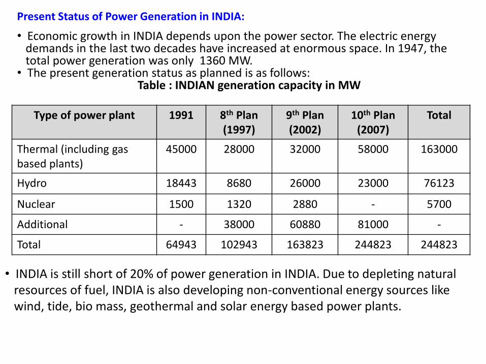
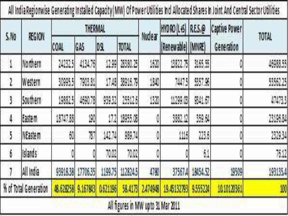
Present Status of Power Generation in INDIA:
• Economic growth in INDIA depends upon the power sector. The electric energydemands in the last two decades have increased at enormous space. In 1947, the total power generation was only 1360 MW.
• The present generation status as planned is as follows:Table : INDIAN generation capacity in MW
Type of power plant 1991 8th Plan(1997)
9th Plan(2002)
10th Plan(2007)
Total
Thermal (including gas based plants)
45000 28000 32000 58000 163000
Hydro 18443 8680 26000 23000 76123
Nuclear 1500 1320 2880 - 5700
Additional - 38000 60880 81000 -
Total 64943 102943 163823 244823 244823
• INDIA is still short of 20% of power generation in INDIA. Due to depleting naturalresources of fuel, INDIA is also developing non-conventional energy sources likewind, tide, bio mass, geothermal and solar energy based power plants.

Prepared by:
SOLANKI JEENESH (120230109048)KANSAGARA RAVI (120230109028)PANDYA UDAY (120230109049)SHAH KRUNAL (120230109029)VALAND VIPUL (120230109061)AGARAWAL PRATIK (120230109060)
