the propulsion committee - ittc.info · pdf filejoint effort of the propulsion committee and...
TRANSCRIPT

Propulsion Committee
Final Report and Recommendations to the 27th ITTC
1 INTRODUCTION
1.1 Membership and Meetings The members of the Propulsion Commit-
tee of the 27th International Towing Tank Conference are as follows:
• Dr. Didier FRECHOU (Chairman), DGA
Hydrodynamics, France • Tom DINHAM-PEREN (Secretary), BMT
Defence Services Ltd, U.K. • Rainer GRABERT, Schiffbau-
Versuchsanstalt Potsdam GmbH (SVA) Germany
• Valery BORUSEVICH, Krylov State Re-search Center, Russia
• Professor Chen-Jun YANG, Shanghai Jiao Tong University, China
• Professor Emin KORKUT, Istanbul Tech-nical University, Turkey
• Professor Steven CECCIO, University of Michigan, USA
• Takuya OHMORI, Japan Marine United Corporation, Japan
• Professor Moon Chan KIM. Pusan Uni-versity, Korea
Five Committee meetings were held as follows:
• DGA Hydrodynamics, France, 30-31
January 2012 • Krylov Institute, Russia, 8-9-10 October
2012 • Pusan University, Korea, 22nd and 23rd
January 2013 • University of Michigan, USA, 23-25 Oc-
tober, 2013. • BMT Defence Services Ltd, UK, 13-14
March 2014.
1.2 Recommendations of the 26th ITTC The 26th ITTC recommended the follow-
ing tasks for the 27th ITTC Propulsion Com-mittee:
1. Provide an update of the state-of-the-art
for predicting propulsion systems emphasing developments since the 2011 ITTC Conference. The committee report includes discussions of the following top-ics:
a. The potential impact of new techno-
logical developments on the ITTC, in-cluding new types of propulsors, azi-muthing thrusters, and propulsors with flexible blades.

b. New experimental techniques and ex-trapolation methods.
c. New benchmark data. d. The practical applications of computa-
tional methods to the propulsion sys-tems predictions and scaling.
e. New developments of experimental and CFD methods applicable to the prediction of cavitation.
f. The need for R&D for improving methods of model experiments, nu-merical modeling and full-scale meas-urements.
g. A review of new developments regard-ing high-speed marine vehicles
2. Provide a review of ITTC Recommended
Procedures relevant to propulsion. The committee report specifically discusses the following topics:
a. Identification of needed changes in
procedures the light of current practice, and, if approved by the Advisory Council, provision of updated re-quirements.
b. Identification of any needed new pro-cedures, including an outline of their purpose and content.
3. Liaise with the Specialist Committee on
Performance of Ships in Service, espe-cially regarding power prediction and consequences of EEDI.
4. Assess where CFD results can be intro-duced to support experimental model testing by monitoring status of CFD to perform full scale powering, resistance, cavitation and wake simulations and their correlation with full scale data. Identify the needs for hybrid procedures combin-ing experimental and numerical methods.
5. Prepare a state-of-the-art review of model-ling and scaling unconventional propul-sion and wake improving devices.
6. Examine methods of target wake simula-tion, e.g. the “smart dummy” approach.
7. Examine wake fraction scaling for twin-screw ships, and show the consequences on existing procedures.
8. Examine the possibilities of CFD methods regarding scaling of conventional and un-conventional propeller open water data, including initiation of a comparative CFD-calculation project.
9. Develop guidelines for hybrid propulsor testing.
10. Continue monitoring existing full-scale data for podded propulsion, if such data is available.
1.3 General Remarks
All the tasks outlined in the terms of refer-
ence were taken in charge by the present committee. The committee had some difficul-ties liaising with other committees concerning Task 3 and Task 4. The portion of this report regarding procedural reviews has been re-cently reported to the AC, which recom-mended that the procedures be a continuing consideration of the next committee. Con-cerning the CFD comparative benchmark, a joint effort of the Propulsion committee and the CFD committee will continue to gather contributions from all the ITTC organisations.

2 STATE OF THE ART UPDATE
Many major international conferences were held since the 26th ITTC conference in 2011:
• 9th Symposium on Particle Image
Velocimetry, 21-23 July 2011, Kobe. • ICOMIA’s 1st International Hybrid Ma-
rine Propulsion Conference, November 2011, The RAI, Amsterdam.
• SMP11 International Symposium on Ma-rine Propulsors and Workshop, June 2011, Hamburg.
• IWSH 2011: 7th International Workshop on Ship Hydrodynamics 16-19 September 2011, Shanghai.
• MARINE 2011- IV International Confer-ence on computational methods in marine Engineering, 28-30 September, Lisbon.
• IMDC 2012-11th International Marine Design Conference, June 2012, Glasgow.
• ICHD 2012- The 10th International Con-ference on Hydrodynamics, 1 - 4 October, 2012, St Petersburg.
• Voith Hydrodynamic conference, June 2012.
• CAV2012- 8th Symposium on Cavitation, 14-16 August, 2012, Singapore.
• ICMT 2012- International Conference on Maritime Technology, 25-28 June 2012, Harbin.
• ONR 29th symposium on Naval Hydro-dynamics, 24 August 2012, Goteborg.
• Journées de l’Hydrodynamique 2012, 21-22-23 Nov 2012, Paris.
• NAV’2012 - 17th International confer-ence on Ships and Shipping Research 17- 19 October 2012, Naples.
• ICETECH 2012, International Confer-ence and Exhibition on Performance of
Ships and Structures in Ice, September 17-20, 2012, Banff,
• 13th Propeller/Shafting Symposium Sep-tember 11 – 12, 2012, Norfolk.
• ONR Naval S&T Partnership Conference event, October 22-24, 2012, Washington D. C.
• IWSH’2011, The 7th International Work-shop on Ship Hydrodynamics, 16-19 Sep-tember, 2011, Shanghai.
• ISOPE 2012 Conference: 22nd interna-tional Ocean and Polar Eng, 17-23 June, Rhodes.
• HIPER, 28-29 Sept 2012, Duisburg. • ISOPE 2013 Anchorage Conference:
22nd international Ocean and Polar Eng, 30 June – 4 July, Anchorage.
• PRADS 2013: The 12th International Symposium on Practical Design of Ships and Other Floating Structures, 20-25 Oc-tober 2013, Changwon.
• FAST 2013, 12th International Confer-ence on Fast Sea Transportation, 2-5 Dec 2013, Amsterdam.
• AMT 2013, The 3rd International Con-ference on Advanced Model Measure-ment Technology for the EU Maritime Industry, 17-19 September 2013, Gdansk.
• OMAE 2013, The 32nd International Conference on Ocean, Offshore and Arc-tic Engineering, June 9 to 14, 2013, Nantes.
• IWSH 2013: The 8th International Work-shop on Ship Hydrodynamics, 23- 25 September, 2013, Seoul.
• SMP’13, The Third International Sympo-sium on Marine Propulsors, 5 – 8 May, 2013, Launceston. The most relevant papers from these con-
ferences and from other technical journals and conferences were reviewed and reported.

2.1 New technological developments
2.1.1 New types of propulsors There is still a tremendous interest con-
cerning Contra-Rotating Propeller (CRP) concepts based on combination of conven-tional propellers and Pods, either on single or twin shafts (see examples on figures 1, 2, 3 & 4)
Figure 1: The first ferry with a podded CRP
propulsion system (Ueda et al., 2004)
Figure 2: CRP Combination of a Rudder Pod
unit and a single propeller (Sánchez-Caja, et al., 2013)
Figure 3: The main propeller (right) with counter rotating, 360 degree azimuthing, ABB Azipod thruster on 200 TEU Container Feed-
er vessel (Henderson, 2013) One advantage of a CRP system when
compared to a single propeller is that, as the two propellers of the CRP share the total pro-pulsive force, the load on a single propeller is reduced, allowing for a reduction in rotation speed. Thus, increased propulsion efficiency can be obtained compared to a single propel-ler of the same diameter.
Figure 4: CRP Electric Propulsion system
(Hideki, et al. 2011) As pointed out by Hideki et al. (2011), in
an electric propulsion vessel, there is no need to connect a large main engine directly to the propeller shaft. Instead, two electric propul-sion motors much smaller in size than the main engine are connected to the propeller shaft through a CR gear. Since the electric propulsion devices are connected via electri-cal buses, the arrangement in the engine room is more flexible than in conventional vessels (Figure 5).

Figure 5: Flexible engine room arrangement
and development of hull form (Hideki et al., 2011)
Therefore, the hull form from midships to
the stern, which is important to reducing fluid resistance, is can be improved compared to vessels with conventional propulsion (Fig. 6).
Figure 6: Comparison of fuel consumption
between conventional vessel and electric pro-pulsion vessel with IHIMU-CEPS (1,230 m3
type chemical tanker used as an example) (Hideki et al., 2011)
Most cargo vessels have only a single
propeller directly driven by a diesel engine. Single screw propulsion offers an efficient hull form. The resistance is lower and the hull efficiency is high owing to the beneficial wake field behind the skeg. This configura-tion provides the most cost efficient solution for most cargo vessels with modest power,
large drafts and little demands on manoeu-vring performance and redundancy.
Full displacement ferries, on the other
hand, usually have twin screws and multi-engine machinery. There have of course been good reasons for these trends. Ferries are of-ten faster and require increased propulsive power. Their draft is often limited, and the propeller loads becomes higher. These factors favour twin-screw solutions, where the power can be divided between two propellers. Safety aspects and fast turnaround in port favours two propellers.
A range of new propulsion concepts for
ferries have been presented in recent years, such as Podded CRP, Wing Pods and Wing Thrusters. These have some features in com-mon in that they do not use a traditional twin shaft line arrangement but instead employ a propeller mounted on the centreline skeg combined with either one or two azimuthing propulsors.
Several recent papers reveal an increasing
interest in Energy saving devices before or after the propeller or within the propeller it-self. The review of new developments on that topic is largely detailed in Section 6.
A few projects using immersed pump-jet
or water-jet have also been published. Pospiech (2012) presented a design of a pump-jet fully integrated with the ship hull (Figure 7). Giles et al. (2011) presented a de-sign of water-jet fully immersed and also fully integrated within the ship hull (Figure 8).

Figure 7: VOITH’s New Propulsion System:
The Voith Linear Jet (Pospiech, 2012)
Figure 8 : WaterJet: Propulsor
(Giles, et al. 2011)
Although the Hybrid sailing vessel is still at a research and development stage, expected fuel energy savings are very promising. Using 9 rigid sails on a cap-size bulker of 180,000DW, Ouchi et al. (2013) forecast a fuel energy savings of at least 20%. CFD was used to estimate the thrust distribution on eve-ry sail for different apparent wind angles.
Figure 9: Hybrid sailing vessel
(Ouchi, et al. 2013)
Figure 10: Thrust force distribution on sails
(Ouchi, et al. 2013) The potential impact of these new
propulsors are listed below: • New procedures are required for self-
propulsion test of contra-rotating propul-sion system and for pump-jets that are in-tegrated within the hull
• CFD calculation might be required to support EFD to assess the performance of Energy Saving Devices.
• A new procedure for self-propulsion will certainly be required for hybrid sailing vessels.
2.1.2 Azimuthing thrusters Two papers (Palm, et al., 2011; Koushan,
et al., 2011) have shown interests on the effect of ventilation on azimuthing thruster perform-ances.
Palm et al. (2011) present a comparative
study between cycloidal propeller and azi-muthing thruster, investigating the effect ven-

tilation on the thrust losses. The blade thrust force of an azimuthing thruster is subject to large variations when ventilation is occurring. Due to its working principle, the cycloidal propeller is less prone to ventilation than the azimuthing thruster.
Figure 11: Cycloidal propeller and azimuthing
thruster at ventilation conditions (Palm et al., 2011)
Koushan et al., 2011 present a similar
study on ventilated propeller blade loadings and spindle moment of a thruster in calm wa-ter and waves. Experimental results are pre-sented for the thrust, torque, and spindle mo-ment of a single blade of a propeller from a pulling thruster under various ventilated oper-ating conditions and in waves.
Figure 12: Azipull Thruster
(Koushan et al., 2011) For all ventilated conditions, it can be ob-
served that a sudden drop in thrust is meas-ured when the advance coefficient becomes less than a critical advance coefficient, which is J ≈ 0.6 for calm water and J ≈ 0.5 for wave conditions. From the critical advance coeffi-cient down to bollard condition, further reduc-tion of the thrust is occurs, though slight thrust recovery is registered close to the bol-lard condition (J = 0). Dynamic variations are analysed using standard deviation and histo-grams. As histograms approximate the prob-ability distribution, they show that the stan-dard deviation values should be handled with some care as the data shows distributions that can be both highly skewed and non-Gaussian. The effect of waves and ventilation on propel-ler torque follows the same trends as on pro-peller thrust. It is observed that the spindle moment changes sign from positive to nega-tive at high J values.
Amini & Steen (2011) performed a series
of model tests on an azimuth thruster model in oblique inflow conditions for different heading angles and at different advance coef-

ficients in pushing and pulling modes. Tests were performed in ventilating and non-ventilating conditions. A novel shaft dyna-mometer was used to measure all six compo-nent forces and moments on the propeller shaft. It was found that the propeller shaft lat-eral force and bending moment were quite large, and thus, the load at the shaft-bearing positions was about three times larger than when only the propeller weight was consid-ered. The results also showed that oblique in-flow due to steering gives higher bending loads than when the propeller is subject to ventilation in the straight-ahead condition. A basic blade element momentum method (BEMT) was used to predict the forces and moments on the propeller shaft in oblique flow conditions. Fairly good agreement was found between the BEMT results and the ex-perimental results.
The authors finally recommend consider-
ing the shaft side forces and bending moments due to steering and oblique inflow in the me-chanical design of the propeller suspension such as thruster housing and propeller shaft bearings.
2.1.3 Flexible blade propulsors
Composite marine structures are attractive because of their ability to conserve weight, reduce maintenance cost, and improve per-formance via 3-D passive hydroelastic tailor-ing of the load-dependent deformations. Manufacturers are proposing carbon fibre propeller of diameter up to 3m.
Several attempts have been made to manu-
facture full size composite propellers and some trials have been conducted in the recent past to compare composite structure and Nickel Aluminium Bronze (NAB) casting.
In 2000, QinetiQ investigated a 2.9 m di-
ameter composite propeller on the Research Vessel Triton, a triple hull warship, nowadays
used as a patrol vessel by the Australian Cus-toms. This composite propeller consists of five composite blades bolted and bonded to a NAB hub. As mentioned by Kane (2001), it was designed to explore the mechanical prop-erties required in this application include me-chanical performance (stiffness, strength and fatigue) as well cavitation inception speed, reported to be 30% higher than the original NAB propeller.
In another example, Airborne Composites
successfully developed composite propeller blades for the Royal Dutch Navy, supplying them with a composite main propeller for an Alkmaar-class mine hunter (Figure 13). This propeller is for a power of about 1400 kW and has a diameter of 2.5m (Black, 2011).
Figure 13: Composite propeller to the RNLN minehunter. (Black, 2011)
Few experiments have been performed at
model scale, one example is Taketani et al., 2013 where different propeller materials have been tested (Figure 14). The results show that the propeller “C” (sintered nylon powders with a laser heating source) presents larger blade deviations than carbon composite mate-rial. For a same propeller loading (Kt), the ad-vance ratio J is significantly reduced (Figure 15).

Figure 14: Model composite propeller
(Taketani et al., 2013)
Figure 15: Model composite propeller per-
formances (Taketani et al., 2013) Propeller efficiency increased in cases
where this deformation was small (Dry Car-bon), since the loss of torque was greater than the loss in thrust. At a certain point, propeller efficiency begins to decline with greater de-formation, suggesting an optimal level of de-formation. Elastic deformation was dominant at the blade tip. This deformation occurred along the direction of thrust and worked as a forward rake.
The cavitation generated after deformation
indicated that such deformation reduced loads at the blade tip and affected pitch angles. This deformation is expected a reduction of pres-sure fluctuations.

In Fluid-Structure Interaction (FSI) analy-
sis, calculations results and model test results were compared. In the case of small deforma-tions, analysis results were consistent with changes in propeller characteristics. For larger deformations, analysis proved relatively inac-curate in estimating the deformation of the entire propeller. Future efforts should target improvements in this aspect.
Manudha, et al. (2013) presented a valida-
tion study that compares results obtained nu-merically using Fluid-Structure Interaction of Finite Element Analysis and experimental re-sults. This validation has been carried on a twisted-bend-twisted coupled hydrofoil. Al-though several simplifications were made for modelling purposes, the consistency between Finite Element Analysis and experimental re-sults were found in good agreement. The knowledge gained through this validation study is extremely helpful in developing an optimisation scheme and an accompanying numerical model that can accurately predict the performance of optimised designs without the need for extensive experimentations.
Extensive studies have been made by
Young (Young, 2007; Young, 2010; Young, 2012; Motley & Young 2012) on flexible blade propellers. Among all those studies, the impact on similarity to be applied for model tests on flexible blade propellers (Figure 16) in order to scale the fluid structure response is of major interest.
Figure 16: Elastic blade deformation on a
composite propeller (Young, 2012). Young (2010) presents a detailed analysis
of the dynamic hydroelastic scaling of self-adaptive composite marine rotors. The scaling analysis main goal is to define how to achieve the same dynamic load-deformation responses between the model and the prototype. This can be achieved by requiring the model to be geometrically similar to the prototype, by re-quiring the effective structural mass and structural rigidities to be the same and by re-quiring the same flow velocity as at full scale:
FSM VV = The following is a simpler way of present-
ing the implication of the similarity laws. When we have to consider testing at model scale with flexible blades, the strain should be kept the same between model scale and full scale. This is to ensure that the displacement, induced by the elasticity of the blade and which changes the angle of attack, will be scaled between model and full scale (Figure 17).

Rigid material
flexible material
VS
Full scale
Model scale
Rigid material
flexible material
Vm
cS
∆cS
∆cm
cm
Figure 17: Strain at full scale and model scale. This is equivalent to say that the strain on
the blade section, that could be defined as the
ratio cc∆
=ε as shown on the figure, should
be the same at model scale and full scale. The strain is related to the stress σ by the modulus of elasticity E:
Ecc σε =
∆=
c : chord length ∆c : displacement E : is the modulus of elasticity σ : is the stress in the material On the other hand, the stress is a function
of hydrodynamic forces and centrifugal forces which means that we can write:
( )
22
23
2
222
2
21
,
DVF
DDF
RmmF
DVFSVF
FFf
proplCentrifuga
proplCentrifuga
propproplCentrifuga
HydroHydro
lCentrifugaHydro
⋅⋅↔⇔
⋅⋅⋅↔⇔
⋅⋅=⋅↔
⋅⋅↔⇔⋅⋅↔
=
ρ
ωρ
ωγ
ρρ
σ
To be more accurate, added mass in addi-
tion to the mass of the blade should be taken into account. But the blade mass as well as the fluid added mass can both be scaled by a factor.
The similarity between model scale and
full scale implies that the same ratio of hy-drodynamic force to centrifugal forces should be kept the same at model and full scale which means the ratio of water density to propeller density should be kept the same:
propprop DVDV
ρρ
ρρ
=⋅⋅
⋅⋅22
22
Because stress is homogeneous to a pres-
sure, we can write that the stress between model scale and full scale is:
22SS
S
MM
M
VV ⋅=
⋅ ρσ
ρσ
In order to get the same kind of strain on
the blades as at full scale, this leads to the fol-lowing relationship :
m
m
S
SmS EE
σσεε =⇔=
Combining all those similarity rules, we
find that:

SM
SM
SpropMprop
SpropMprop
SS
S
MM
M
M
M
S
SMS
VVEE
VV
EE
===
⇒
=
⋅=
⋅
=⇔=ρρ
ρρ
ρρ
ρσ
ρσ
σσεε
22
This demonstrates that with same blade
material at full scale and with the same full scale speed, the strains and loading will be the same.
However, it is problematic to run model
test following these requirements, as the simi-larity conditions are very difficult to achieve on the model scale for the followings reasons:
1. Manufacture of the model scale propeller
(e.g. 250 mm in diameter) is required to have the same isotropic material proper-ties as that of the full scale (e.g. 2.5 m) propeller; this is difficult to achieve, es-pecially with composite carbon fibre ma-terials at the root and the tip.
2. Testing at full-scale speeds necessitates performing the test at very high static pressures in order to avoid any cavitation. In practice, those conditions cannot be achieved in a towing tank, but they can be achieved in cavitation tunnel.
It seems more reasonable to use CFD
which might use a combination of fluid and structural modelling (Young, 2007; He et al., 2012). Meanwhile special care should be taken for the composite structural characteris-tics, for, as pointed out by Young & Motley (2011), the variations in material parameters and material failure initiation models lead to a much wider spread of propeller performance characteristics, operating conditions, and safe operating envelopes for an adaptive propeller compared to a rigid propeller.
2.1.4 Podded propeller in Ice and bubbly
flow Due to the growing interest of a potential
new northern route induced by the global warming, several studies have been carried on propeller ice blade load impact (Brouwer et al., 2013; Sampson et al., 2013), propeller wash (Ferrieri et al., 2013), and cavitation (Sampson & Atlar, 2013).
Figure 18: Picture from a high-speed cam-era of a propeller entering an ice ridge
(Brouwer et al., 2013).

Figure 19: Propeller Thrust, Torque reduc-
tion as a function of void fraction (Kawakita, 2013)
Brouwer et al. (2013) developed a meas-
urement setup in which a 6 components bal-ance is measuring the 6 degrees of freedom forces and moments on a single blade of the podded propeller. This measurement setup was used to measure the ice impact in a model test at the AARC facility of Helsinki.
A few papers (Kawakita et al. 2011, and
Kawakita, 2013) have discussed the effect of air lubrication of a ship hull on propeller effi-ciency. In recent years, air lubrication systems have been attracting attention as a method of reducing carbon dioxide emissions from ships by reducing the total resistance of the ship. The bubbly flow generated travels to the stern such that the propeller may partially work in two-phase flow modifying the thrust and torque (Figure 19).
2.2 New Experimental Techniques and
Extrapolation Methods
2.2.1 3D flow visualization Only one paper dealing with 3D flow in-
vestigations around the propeller caught the attention of the committee. Pecoraro et al. (2013), present a 3D flow velocity measure-ments, using the LDV technique. The major outcome of the analysis is that the effect of the propeller suction, which increases the ve-locity, extends upstream at a distance about 1 propeller radius, and that the flow fluctuation induced by the blade passage extends up-stream to a distance of about 4 propeller radii. The propeller is able to reduce the size of the detached area longitudinally and transversally but is not able to remove totally the flow separation. The boundary of the separated flow can be identified by using the skewness coefficient, which allows a better identifica-tion of the extension of the separated flow.

Figure 20: Axial velocity at R/R=0.7 with
and without the propeller (Pecoraro et al., 2013)
Manufacture / control of Model Propellers
For measurement of blade geometry, Dang et al. (2012) are presenting a new optical technique based on digital photogrammetry. In order to have control on the accuracy of the blades, the propeller is optically scanned at its design pitch. The results are compared to the theoretical geometry and the deviations are determined and presented in 3D images of the model propeller (Figure 21).
2.2.2 Propeller manufacturing
Only one paper concerning new tech-niques for manufacturing model propeller, (Taketani et al., 2013) was found. A model propeller was manufactured by sintering ny-lon powders with a laser and was then com-pared with aluminum made propeller and car-bon composite propeller (see Figure 14). The-
se results of this work are discussed in Sec-tion 2.1.3.
Figure 21: Optical scan on a CP propeller
(deviation from its theoretical geometry, pres-sure side –suction side) (Dang et al., 2012)
2.2.3 Non-stationary blade force meas-
urements Non-stationary blade forces measurement
on propellers at model scale is still a challeng-ing issue. Funeno et al. (2013) developed a blade spindle torque sensor built in the pro-peller hub (Figure 22) to measure blade torque of a controllable pitch propeller operat-ing in off-design conditions and high propel-ler loading.
Just to mention that there is an increase in-
terest (DNV rules, 2010, 27th ITTC Specialist Committee on Hydrodynamic Noise) for this topic that might have some impact on propulsor design, on the procedure to measure propulsor radiated noise, on the prediction of the cavitation inception point, because cavita-tion is largely increasing the radiated noise of a propeller (Briancon et al., 2013; Bosshers et al., 2013).

Figure 22: Propeller shaft thrust and
torque sensor and the blade spindle sensor (Hagesteijn, 2012; Funeno, 2013)
2.3 New benchmark data A sensitivity study of the testing parame-
ters for Propeller alone and the Podded propulsor open water test have been carried out by CTO (Głodowski et al., 2013). The paper is a summary of the large test campaign that was performed within the framework of the Hydro-Testing Alliance Network of Ex-cellence, Joint Research Program 4 (JRP4), based on the so-call ABB case. Before that, a first benchmark had shown large discrepan-cies of about 5.9% even for the POD propeller open water test (Veikonheimo, 2006). Then a second benchmark testing program has been launched through the Hydro Testing Alliance (HTA) European Project to standardize the testing procedure in order to understand the causes the discrepancies found in the first test and to define recommendations for the testing procedure/setup of Podded propulsors. It was determined that using a same propeller model, a same POD housing, the same aft fairing for the propeller open water test, reduces the dis-crepancies of the results between the different facilities.
The final conclusions of this benchmark-
ing test program were in line with the recom-
mendations given in the 7.5-02-03-01.3 Pro-pulsion, Performance Podded Propulsion Tests and Extrapolation. The authors recom-mend having a aft fairing cone to rotate with the propeller and having a separate pre-test with a dummy hub to correct with the propel-ler open water test results which is a first al-ternative recommended in the 7.5-02-03-01.3 Propulsion, Performance Podded Propulsion Tests and Extrapolation.
2.4 Application of computational meth-ods
With respect to the propulsive perform-
ance, the major interest is still in developing and applying CFD (mainly RANS) models for self-propulsion simulation at model scale, in-cluding different approaches to extract the effective wake field. Meanwhile, such simula-tion at full scale began to appear, which pro-vides a new perspective for studying the Rey-nolds scale effects. On the other hand, there is a pronounced increase in efforts devoted to the research of scale effects on energy saving devices, such as the pre-propeller stators/fins and ducts, the CLT propeller and the PBCF, and on multi-component propulsors, such as ducted, contra-rotating, and podded propellers.
2.4.1 Self-propulsion and effective wake
field In Castro, et al. (2011) the feasibility of
self-propulsion simulation at full scale was demonstrated for the KCS, using a DES model and a dynamic overset approach. The propulsion factors were analyzed from simu-lated full scale resistance, open water, and self-propulsion performances, and compared with those obtained from model scale simula-tions and experiments. The SFC based on EFD and ITTC extrapolation procedure was larger than that based on model and full scale computation results. The computed full scale open water thrust was close to, while the

torque was slightly lower than the model scale EFD data. The simulation results of full scale self-propulsion agreed well with EFD data, except for the torque coefficient (and hence the relative rotative efficiency). Through comparison of simulated stern flows, it was shown that the propeller working behind the hull experiences an inflow of higher axial ve-locity and uniformity due to the thinner boundary layer at full scale than at model scale, which results in favourable effects on propeller and propulsive efficiencies, axial loading fluctuations, as well as the level of bending moment around horizontal axis.
Figure 23: The overset grid system for
KCS (Castro, et al., 2011) Villa, et al. (2012) presented a viscous/
inviscid coupled approach for the simulation of self-propulsion based on a RANS and an unsteady BEM solver. Extraction of the effec-tive wake field was made at a plane 0.2D up-stream of propeller blades by using the time-averaged induced velocities computed by the BEM code. Simulations were conducted for the KCS propelled by KP505 at model scale, Fn = 0.26. It was shown that the iterative ap-proach converged fast and the CFD and EFD results of total resistance, propeller rotation speed, and the velocities at a section in pro-peller slipstream correlated well. In addition the results from an actuator disk model (hav-
ing axial force only) were also presented to compare with those from the more accurate BEM-based body force model.
Sakamoto, et al. (2013a) presented re-
search on a RANS simulation of the resis-tance, open-water, and self-propulsion per-formances for a twin-skeg container ship at model scale, together with towing tank ex-periments. An in-house FVM solver and the Spalart-Allmaras one-equation turbulence model were used. The propeller was modelled by body force distributions computed by a simplified propeller theory. By using three sets of block-structured grids having a re-finement ratio of 2 , the uncertainty analysis for resistance and self-propulsion coefficients was conducted with the V&V method rec-ommended by the 25th ITTC. It was con-cluded that the CFD solver was capable of predicting the resistance and self-propulsion performances for the low L/B twin-skeg ship, though it could be improved by implementing real-geometry propeller computations.
In Rijpkema, et al. (2013) different ways
to extract the effective wake field and their influences on predicted propeller performance behind the hull were studied. Two in-house RANS solvers coupled with a BEM propeller code were used in a comparative investigation of the self-propulsion computations for KCS. The body force field was imposed at the blade positions (instead of the propeller disk posi-tion) by interpolation of BEM output. The ef-fective wake field was obtained by subtract-ing the time-averaged propeller induced ve-locities computed by BEM from the RANS-computed velocity field of the hull-propeller system. The numerical results indicate that the effective inflow accelerates towards the pro-peller, see Figures 24 and 25, hence the axial location where the effective wake is defined has an influence upon the predicted propeller rotation rate.

Figure 24: The axial locations used to
compute the effective wake field. The con-tours represent the body force distribution in
the RANS simulation. (Rijpkema, et al., 2013)
Figure 25: The RANS/BEM coupled re-
sults of effective wake velocities at different locations, where the acceleration of effective
wake flow towards the propeller disk is shown. (Rijpkema et al., 2013)
By using the effective wake field linearly
extrapolated from upstream locations to the propeller reference plane, the accuracy of propeller performance prediction was im-proved. In addition the effective wake fields predicted by a RANS-BEM coupled method and by the more traditional force-field method based on the nominal wake and propeller thrust loading were shown to be quite differ-ent, being the former method more accurate with respect to the propeller performance when the extrapolated effective wake was used.
In the viscous/potential flow coupled ap-proach by Sánchez-Caja, et al. (2014b) a lift-ing line model for the propeller in effective wake was used to compute the body forces which were circumferentially averaged and distributed on the propeller's reference plane, or the actuator disk. However, it was shown from open-water computations that the pro-peller-induced velocities by the lifting-line model were different (and not accurate due to the assumptions made in the model) from those predicted by RANS using the equivalent body force distributions, which would bring about errors in the effective wake so predicted.
For the three components of induced ve-
locity vector, a procedure was proposed to quantify the correction factors for such errors due to the lifting line model through coupled computations for the open-water propeller. Numerical results indicated that the correction factors at a reference thrust loading condition could be applied, with just a little loss of ac-curacy, to another condition where the thrust loading was within ±50% of that at the refer-ence condition. This feature might allow for savings in the computation of the correction factors. The procedure was applied to a hybrid CRP pod configuration, where it was shown that the errors in thrust and torque were about ±5% without corrections for the effective wake. As the interaction between forward and aft propellers was treated as part of the effect wake, the procedure would make it possible to use single propeller design methods for the CRP.
In the naval context, Liefvendahl, et al.
(2012) presented near-wall modelled LES simulation results for the SUBOFF+E1619 configuration, using fine (16M) and coarse (8M) grids respectively. The authors found that the coarse grids resulted in a slightly higher level of unsteadiness in the wake flow, but a higher level of fluctuation in blade thrust, and concluded that much higher grid

resolution would be needed for more accurate simulation of unsteady flow and propeller forces. Zhang et al. (2012) presented RANS simulation results for another submarine hull/propeller configuration to investigate the effects of free surface on resistance and self-propulsion. The CFD and EFD data correlated well, both indicating that the free surface ef-fect on resistance was negligible below a cer-tain centreline submergence (h/L > 1/3), while that on the self-propulsion factors was even smaller.
2.4.2 Energy-saving devices
The scale effects of the Wake Equalizing Duct (WED) and the Vortex Generator Fins (VGF) on propulsion and fluctuating pressure were numerically and experimentally investi-gated by Heinke et al. (2011). The RANS predictions of the nominal wake at model- and full-scale indicated that the propeller in-flow would be largely altered by the scale ef-fect, while the WED, or the VGF alike, could reduce the wake peak distinctly. The CFD re-sults were utilized in designing the VGF. Concerning the scale effects on propulsion factors, discrepancies existed between the RANS and ITTC '78 predictions, especially for the WED, though the hull efficiencies happened to be close to each other.
Huang et al. (2012) presented an investi-
gation of the WEDs for a bulk carrier based on RANS simulations with a body-force pro-peller model and experiments. Both work in-dicated that, for a fixed tilt angle, the asym-metric arrangement of port and starboard half-ducts was quite important for maximizing the energy-saving rate. The RANS-based energy-saving was slightly lower than the model test result.
The effects of symmetrical and asymmet-
rical WEDs for a VLCC were investigated by Yu et al. (2013) based on RANS simulations and a real-geometry propeller model. In this
study, the extrapolated energy-saving rate from the RANS results was somewhat higher than that from the model tests.
In Guiard et al. (2013) the procedure for
designing the Mewis Duct® was presented in brief. The fin setting designed on the basis of model experiments was subject to further ad-justments to make full use of the full scale wake flow. In this final step of design, RANS simulation results at model and full scale pro-vided the designer with a reference. Despite the lack of full scale wake data, it was as-sumed that existing procedure for scaling the effective wake fraction was applicable to scal-ing the nominal wake fraction, too. And it fol-lowed that the full scale nominal wake distri-bution would be deemed as a good prediction if its disk-average was close to the nominal wake fraction predicted by an accepted wake scaling procedure.
For a mid-size tanker, the influences of
grid size, turbulence model, and surface roughness on predicted nominal wake flow and fraction were investigated. For a suffi-ciently fine grid set of high quality, it was shown that the nominal wake fractions were under-predicted with both SST k-ω and RST turbulence model if the hull was treated as a smooth surface. The surface roughness value was shown to have important impacts on the predicted wake distribution and fraction. In terms of the predicted wake fraction, the RST model performed the best for the typical roughness value of 0.188mm, while the SST k-ω model needed a much larger roughness of 0.5mm to yield similar result. Meanwhile, in the two cases the simulated wake flows were quite different (Figure 26).
A numerical investigation was made by
Huang S.-Q, et al. (2012) for the effects of the Pre-Swirl Duct (PSD), a combination of a pre-positive duct and several pre-swirl stators. Four cases having different duct and/or stator

section profiles were simulated. The device's effects of equalizing and pre-swirling the pro-peller inflow were confirmed by the RANS results. It was concluded that, among others, the stator pitch angle was a key parameter for the energy-saving predicted.
Figure 26: The full scale nominal wakes
of a tanker predicted by RANS simulations. Upper: RST model, roughness 0.188mm; lower: SST k-ω model, roughness 0.5mm. The axial wake fractions were 0.313 and
0.318 respectively, against the value of 0.316 estimated by using the model wake fraction obtained from RANS and the RST model.
(Guiard et al., 2013) In Haimov et al. (2011) the scale effects
on ducted and CLT propeller performance in open water were investigated. The RANS computations were conducted with a com-mercial solver, using unstructured tetrahedral grids. In respect to the CLT propeller, the comparison between model and full scale re-sults indicated that the increase in efficiency at full scale was primarily due to the increase
in thrust, in comparison to the decrease in torque. Meanwhile, the RANS-predicted scale effect was smaller when compared with a scaling procedure practically used for the CLT propeller. In addition, the RANS-predicted scale effects under lighter loading condition were more pronounced and much larger than for conventional propellers.
Sánchez-Caja, et al. (2014a) investigated
the influences of endplate geometry on the efficiency of the CLT propeller based on full-scale simulations for two propellers in open water using an in-house RANS solver and Chien's low Reynolds number turbulence model. To reduce numerical uncertainty, a template-based procedure was devised for generating block-structured grids having the same topology and similar grid size distribu-tions for different endplate geometries. The grid dependency was studied by using three successively coarsened grid sets. The largest difference was 1.3% in torque between the coarse and fine grids. Twelve cases were in-vestigated for a 4-bladed propeller with varied endplate geometries. It was shown that the contraction of endplate affects both efficiency and thrust, and lighter loading on endplate improves the efficiency; the forward sweep improves the efficiency, too. From a theoreti-cal viewpoint, the working mechanism of endplate was analyzed based on radial distri-butions of bound and free vortices obtained by integrating the flow velocities. The results indicated that for cases of higher efficiency the tip vortex was weaker, consequently the induced drag was smaller.
The RANS-based investigation was fur-
ther conducted by Sánchez-Caja, et al. (2014c) of scale effects on the 4-bladed CLT propeller. The propeller efficiency at full scale was 10% higher than at model scale, where 2% was from the endplates due to the reduction in torque. The circulation distribution at full scale was higher in magnitude but lower in

slope, confirming the results of higher thrust coefficient as well as efficiency than at model scale. The strong dependency of efficiency scaling on the type of flow regime at model scale was pointed out. In some cases, effi-ciency-based ranking for endplate designs at model scale were different from that at full scale.
2.4.3 Multi-component propulsors
Kinnas, et al. (2013) presented a method based on potential/viscous flow iteration by treating the duct-induced velocity field under propeller action as the effective wake for the propeller, for the purpose of computing pro-peller sheet cavitation under inclined inflow. The comparison of computed and measured open-water performances of a ducted propel-ler indicated that the iterative method was able to predict the hydrodynamic performance with good accuracy, especially for the thrust.
In Bulten, et al. (2011) a RANS approach
was employed to predict and analyze the Reynolds scale effects on the open water per-formance of a ducted propeller and on the nominal wake of a ship hull. In regard to the ducted propeller, RANS results for the Kaplan 4-70 propeller in 19A nozzle indicated that the increase in open-water efficiency at full scale was mainly attributed to the decrease in propeller torque, while the duct and propeller thrust coefficients were quite close between model and full scales. An analysis was made to explain the results by employing the pump theory. It was argued that the reduced viscous loss at full scale had resulted in an increase in the dimensionless flow rate through the noz-zle. Consequently the propeller loading was reduced at full scale, which resulted in de-creases in both thrust and torque of the pro-peller, apart from the traditionally acknowl-edged scale effects on propeller thrust and torque.
The simulation approach was further ex-tended for use with steerable thrusters in Bulten, et al. (2013). In this case the RANS-predicted model and full scale performances of the thruster in a straight course indicated that the efficiency increase at full scale was mainly due to the increase in unit thrust, in which the axial forces on the duct and propel-ler housing made more contributions. For the bollard pull performance, a generic prediction method was proposed by making use of the pump theory and RANS flow data, and the influence factors wherein were discussed. In respect to the transient thrust and torque, it was found from unsteady simulations that their fluctuation amplitudes were larger in free sailing condition than in bollard pull con-dition, and were asymmetrical about the steer-ing angle. The reason for the asymmetry was further analyzed by comparing the contribu-tions from the lateral force and the eccentric-ity of thrust.
To investigate the capability of the RANS
simulation approach for ducted propeller un-der non-cavitating and cavitating conditions, CFD and EFD results were compared by Xia et al. (2012). The RNG k-e model with wall function, and Sauer and Schnerr's mass trans-fer model were employed for turbulence clo-sure and cavitation, respectively. Block-structured and unstructured grids were used for fully wetted flow, where the predicted open water characteristics both agreed well with the measured one, except for lightly loaded conditions where the flow separation occurring near the duct trailing edge was not well simulated. Under developed cavitation conditions, although the numerical approach was able to simulate thrust breakdown, the thrust and torque were over-estimated in gen-eral and there were significant increases in predicted thrust and torque towards the start-ing point of thrust breakdown. It was con-cluded that the unstructured grids were more suitable for modelling the tip-clearance flow.

Sakamoto et al. (2013b) attempted model and full scale viscous CFD computation of a POD propulsor in open water configuration. The propeller was represented by a body-force model. The full scale propulsive effi-ciency estimated by the full scale CFD com-putation was higher than that of ITTC predic-tion method applied to the model scale CFD result (Figure 27). The discrepancy comes from differences in the resistance of the POD drive, caused by the changes of the flow field such as the position of the separation line.
Figure 27 Comparison of propulsor open
water characteristics: unit-based, Exp. vs CFD vs Exp. with ITTC correction, model and full
scale. (Sakamoto et al., 2013b) Fujisawa (2013) discussed the scale effect
on the POC of contra-rotating propeller by CFD. Fore and aft propellers of a CRP system have different trends in scale effect. It is sup-posed that the turbulence caused by the fore propeller hastens the flow transition of aft propeller (Figure 28).
Figure 28: Scale effects on each of fore
(subscript “f”) / aft (subscript “a”) propeller open performance (Fujisawa 2013)
In the ocean engineering context, thruster-
hull interactions are important for DP system design. The numerical modelling of such in-teractions is challenging especially under the bollard condition. Maciel et al. (2013) pre-sented a RANS-based approach to this prob-lem and investigated its feasibility and accu-racy in terms of predicted thrusts and wake flows for three typical cases, i.e., a ducted thruster model working in open water, under a flat plate, and under a barge. The propeller was modelled by an actuator disk where the body force distributions were determined by fitting RANS results. By using a small current speed (J = 0.028) together with careful choice of numerical schemes and parameters, simula-tions under the bollard condition were real-ized with reasonably good agreement with the measured forces on the thruster and the plate/barge, and with the wake flows meas-ured by PIV, see Figure 29 for example.

Figure 29: Comparison of RANS-
simulated axial velocity contours with the wake trajectory measured by PIV for the tilted
thruster working under the barge with bilge keel. (Maciel et al., 2013)
2.4.4 Design & optimization
Vesting et al. (2013) presented a multi-objective optimization study for a cruise ship propeller by considering the open-water effi-ciency as well as blade cavitation and induced pressures in a given wake field. A vortex lat-tice code was used to predict hydrodynamic forces and sheet cavitation, while a boundary element code to calculate the induced pres-sures. The codes were driven by a genetic al-gorithm. The blade geometry was parametri-cally represented in the traditional way, and morphed with B-spline curves in order to re-duce the number of design variables. A sensi-tivity analysis (SA) was carried out for the geometric parameters with regard to their im-pacts on the performance aspects being con-sidered. Starting from the baseline geometry which was already manually optimized and proven to be a good design by model experi-ments, further optimizations were conducted with all and a selected set (according to the results from SA) of the design variables, re-spectively. The latter case proved to converge faster than the former one. The results indi-cated that induced pressures could be further reduced. Satisfaction of the constant-KT con-straint, and the resolution for interaction ef-fects among parameters remain as issues in the method.
2.4.5 Off-design operating conditions Hur et al. (2011) measured propeller shaft
torque and stress for an LPG carrier in a crash stop operation during sea trials. RANS simu-lations were carried out using the RPM and ship speed data from sea trial. Both steady and unsteady RANS results for torque were close to each other at full astern, and also to the sea trial data when the ship wake was ig-nored, suggesting that steady simulation could be used for blade strength analysis at initial design stage.
In Sileo, et al. (2011) RANS simulations
were carried out for a self-propelled chemical tanker model under reversing condition, and the computed forces were compared well with measured data. Based on the numerical results of flow and hull pressure etc. the reasons for a reversing single-screw ship to deviate from straight course were analyzed.
The flow and forces under crash astern
conditions were simulated by using LES for a single propeller, Jang, et al. (2013), and a ducted rotor with upstream stator rows, Jang, et al. (2012), and compared with model test data with good quantitative agreement. The typical flow feature was a highly unsteady vortex ring having its averaged location and strength changing with the advance ratio, Fig-ure 30. Flow separation from the trailing edges resulted in high-amplitude, transient blade loads and the lateral force. For the ducted rotor-stator configuration, the same ring-vortex structure existed and numerical results indicated the lateral force came mostly from the pressures on duct inner surface due to tip-leakage flows. The LES model was fur-ther applied by Verma et al. (2012) to investi-gate the effect of hull on the propeller in crash astern operation. In addition to the ring vortex structure in the vicinity of blade tips, in the presence of the hull there existed a recircula-tion zone upstream of the propeller. The lead-

ing and/or trailing edge flow separation con-tributed to the transient lateral force.
In Amini et al. (2012) the feasibility of
different numerical methods was investigated for predicting the six-component forces acting on the propeller blades of an azimuth pod thruster working in pulling and pushing modes within a ±30° range of the oblique in-flow angle. The computational methods in-clude a blade element momentum theory (BEMT), a boundary element method (BEM), and a RANS method. Being based on Glau-ert's momentum theory, the vortex cylinder model, and the blade element theory, the BEMT for oblique inflow was able to com-pute the blade forces and moments in a quasi-steady manner while the nominal wakes due to the hull and thruster housing were taking into account. Blade forces and moments ob-tained from the three methods were compared with those measured in a towing tank with a six-component force dynamometer embedded in the propeller hub. The MRF-based RANS model performed the best in both pulling and pushing modes, and the prediction accuracy was further improved when unsteady effects were accounted for by using sliding meshes. The two potential flow methods were able to predict the variations of blade forces and moments with oblique flow angle reasonably well, although under and over estimations were seen in the six components made either by the BEMT or by the BEM.
Figure 30: Circumferentially averaged flow around a propeller under crash astern opera-tion. Upper: J = −0.5, lower: J = −1.0. (Jang,
et al., 2013)
2.5 Experimental and CFD methods for the prediction of cavitation
Methods to predict cavitation on marine
propeller blades has been classified by the 26th CFD Committee as interface tracking, discrete bubble dynamics and interface cap-turing methods. The interface tracking meth-od is used to predict steady attached sheet cavitation in inviscid flow. In the discrete bubble dynamics method, cavitation is mod-elled as an interaction between bubble nuclei and pressure field variation. Bubble size gov-erned by Rayleigh-Plesset Equation. This type of method is applied to predict inception, travelling bubble and nuclei effects. The inter-face capturing method assumes that the flow

is a mixture of multi-phase flow and a flow solver and a cavitation model is used to de-termine the vapor volume of fraction.
Sipila and Siikonen (2012) have investi-
gated the numerical simulation of cavitating model size PPTC propeller of SVA Potsdam in uniform inflow. The propeller wake field is calculated with Chien’s k-ε turbulence model in the non-cavitating and cavitating conditions and with Menter’s SST k-ω turbulence model in wetted conditions. The effect of the exper-imental coefficients in Merkle’s mass transfer model on the cavitating tip vortex is studied systematically. The calculations are conduct-ed with FINFLO, a general-purpose CFD code and numerical results are compared with model test results performed by SVA Pots-dam. Particular attention was paid to the grid resolution. The numerical results and the ex-periments show a reasonable correlation with each other.
Figure 31 The surface grid on the blade
and a slice of the grid in the slipstream that has been adjusted to follow the wake of the
blade and the tip vortex at the finest grid level Sipila & Siikonen (2012).
Lu et al. (2012) performed numerical sim-
ulations of the cavitating flow around a typi-cal yacht and Ro-Pax vessel propeller operat-ing in open water but mounted on an inclined shaft. They used Large Eddy simulation (LES) and Unsteady Reynolds-Averaged Navier-Stokes (URANS) in combination with
a Volume-of-Fluid implementation to capture the liquid-vapor interface and a transport equation-based method for the mass transfer between the phases. They compared the nu-merical results with the experiments. Their results indicate that a potential flow solver is not suitable for prediction complex sheet type, and root type of cavitation. RANS has partly captured the dynamic evolution of the sheet close to the tip region as well as the occur-rence of the root cavitation. LES captured the correct location and dynamic behavior of the vortical structure (as was not the case for RANS) as shown in Figure 32. However the grid resolution is still an issue for the LES computation compared to those for the RANS.
(a) (b)
Figure 32: Blade pressure with iso-surface of the second invariant of the vorticity ∇v − ∇×v , indicating vortical structures, as pre-
dicted by RANS (a) and LES (b) Li et al. (2012) also made an attempt to
predict numerically cavitating flows for the INSEAN propeller E779A operating in uni-form and non-uniform wakes. A multiphase mixture flow RANS solver and Zwart’s mass transfer model are used to predict the turbu-lent cavitating flow. Turbulence is modelled by a modified SST k-ω model. In the uniform wake, the predicted sheet cavities are stable and have similar patterns as observed in the experiment. They found that there are unre-solved issues like the cavitation inception or disappearance leading edge cavity position, differences in the maximum cavity area and its location.

2.6 The need for R&D There is still a need for continued R & D
to aid in the improvement of model experi-ments, numerical modelling and full-scale measurement. Specific areas needing im-provement are the following:
• model and full scale meaaurements of
propulsors in off-design conditions • full scale measurements of ship propul-
sive gain due to the use of Energy Sav-ings Devices (ship configurations with and without)
• propulsive performances on composite propeller at full scale and model scale with possible measurement of blade de-formation and torque
• full-scale measurements on Hybrid Con-tra-Rotating Shaft Pod propulsors
• EFD and CFD (e.g. RANS) simulation of the effect of varying Reynolds number on the performace of blade sections.
• full scale measurement of waterjet inlet flow velocity fields
2.7 High-speed marine vehicles Performance prediction of high speed craft
with a view to improve model/ship extrapola-tion techniques and additional investigations into scaling effects of waterjet and surface piercing propeller propulsion tests are focused on in this review.
2.7.1 Powering and performance predic-
tion Numerous studies are related to catamaran
concept including well-known typical high-speed multi-hull model DELFT 372 catama-ran for which new tests were also carried out and a large database is still in construction. Development of CFD tools for high-speed
marine vehicles indicates its wide applicabil-ity in hull optimization processes and ac-ceptable accuracy for power prediction.
Kandasamy et al. (2011) reported on hy-
drodynamic optimization of multihull ships. Simulation based design (SBD) was applied for the resistance optimization of two waterjet propelled high-speed ships, namely JHSS (Joint High Speed Ship) which is monohull and the DELFT catamaran. The adopted SBD explores the concept of variable physics ap-proach for the Delft catamaran which shows strong waterjet hull interaction effects. The design optimization yielded geometries with significant resistance reduction for both JHSS and Delft catamaran. Tahara et al. (2011) also reported on the numerical optimization of the initial design of two waterjet propelled ships JHSS and Delft catamaran.
Figure 33: Axial velocity contours on a
cross-cut inside the waterjet inlets (top figure) and aft view of the powered JHSS with water
exiting the waterjet inlets and free surface colored by wave height (Delaney et al.,
2011). Zaghi et al. (2011) reported on an experi-
mental and numerical test campaign of fast catamarans being done at INSEAN facilities. The CFD models employed second order solver for the unsteady incompressible Navier Stokes equations. The effect of demi-hull sep-aration by means of both experimental and CFD tools is reported. Delaney et al. (2011) performed RANS calculations on the JHSS that was equipped with four waterjets. Fig.33

indicates that the flow through the waterjet inlets is extremely complex including interac-tion with the free surface and these features captured correctly by CFD. Computed pro-pulsion is within 6% of experimental meas-urements which is quite good considering slight differences between the computational model and experimental conditions.
Skejic et al. (2012) theoretically investi-
gated the problem of effective power re-quirements in calm water for high-speed ves-sels (monohulls and catamarans) at prelimi-nary design stage. The effective power re-quirements have been derived from a modi-fied version of Doctor and Day (1997) meth-od which predicts total vessel resistance in calm water, introduced modifications are mainly related to different methods of wave making resistance estimation for deep and shallow water. In particular for deep water the influence of the viscosity effects according to different wave theories is analyzed and demonstrated significant influence to effective power predictions. The wave making re-sistance and effective power are also analyzed in the finite water depth where they depend on the depth Froude number. The results are compared with available published results and show good agreement.
Eslamdoost et al. (2013) developed and
validated the method, which is based on the potential flow assumption with non-linear free surface boundary conditions to model the waterjet-hull interaction. By means of this method, assuming that each of the investigat-ed parameters independently influences the resistance change, the resistance increment of the hull is estimated through a linear expan-sion in a Taylor series, which is a function of the hull sinkage, trim and the flow rate through the waterjet unit. Knowing the mag-nitude of each single parameter separately helps to understand the physics behind the thrust deduction and may aid in the optimiza-
tion of the hull/propulsor configuration. Also it sheds some light on the reason for the nega-tive thrust deduction fractions sometimes found on waterjet driven hulls. Broglia et al. (2011) reported on calm water and seakeeping experimental investigation for a fast catama-ran DELFT 372. The main issue of the paper is the interference effect between the hulls whilst former numerous studies published concerned with catamaran with the nominal separation. A monohull was tested as well. The large measurements collected provide a valuable database for CFD validation. Con-clusions on the interference effects are made. The total coefficient curve shows the presence of two distinct humps one around Fr = 0.3 and one around Fr = 0.5. The peaks in the CT are more accentuated for the catamaran than for monohull. Moreover it has seen that the se-cond hump is strongly dependent on the sepa-ration length.
Figure 34: Calm water tests: CT versus
speed (Broglia, et al., 2011) Broglia, et al. (2012) provided the results
of velocity field measurements around the Delft catamaran 372 model advancing in steady drift course. The purpose of the work is the characterization of the strong vortex structures generated along the keel of each demi-hull and to provide a valuable experi-mental data set for CFD benchmarking in se-vere off design conditions (such as during tight maneuver or when advancing at high drift angles). Zurcher, et al. (2013) discussed experimental set-up, model manufacturing and preparation for the model tests to be car-

ried out using a load-varied self-propulsion testing technique and reported that a set of sea trials database is available to establish a methodology for waterjet self-propulsion test-ing based on the model tests.
2.7.2 High speed vehicle concepts
Besides widely used catamarans other concepts of high speed vehicles were also re-ported, including variations in their design by CFD and model experiment. Bono, et al. (2012) introduced the hybrid hull structure between a catamaran and a monohull (Y-shape) combining the positive characteristics of monohull (better maneuvering and less high frequency roll motions) with those of multihull (less resistance and good stability). Static and dynamic behaviors of the Y-hull model were studied in the towing tank exper-iment. Numerical simulations were carried out to optimize the hull shape. Brizzolara, et al. (2011) reported on hydrodynamic design of a family of hybrid SWATH unmanned sur-face vehicles. Modern CFD automatic para-metric optimization has been developed as an instrument for design and the final design was validated by RANS approach. Eastgate, et al. (2011) discussed the design of a submersible aircraft concept along with the results of some tests.
McDonald, et al. (2011) reported on ana-
lyzing and comparing Tri-SWACH, monohull and trimaran concepts. Fu, et al. (2011) pre-sented experimental and computational results for a Deep-V monohull planing hull. Planing craft model test program focused on collect-ing a wide range of types of measurements. Due to complexity of planning craft hydrody-namics model size was maximized (thus min-imizing scaling errors) while still being able to obtain a wide Froude number range (0.31 to 2.5). Knight, et al. (2011) discussed the methodology of multi-objective particle swarm optimization of a planning craft with uncertainty. Zheng, et al. (2012) presented
hull form design and performance evaluation of a Surface Planing Submersible Ship (SPS) which can sail in planning mode on the sur-face at high speeds and cruse underwater at low speeds. Finite volume based CFD method that took into account dynamic sinkage and trim were used for design of hull form. Pre-liminary model tests are also reported. Mosaad, et al. (2012) presented simple meth-od to predict required power for WIG craft that can be used successfully in the prelimi-nary design stage, using an iterative computer program. The output of this proposed method gives the logic and acceptable performance of the WIG craft compared to the related plan-ning hull.
2.7.3 Propulsors
Hwang, et al. (2011) developed the design procedure for developing trans-velocity pro-pellers (TVP). Trans-velocity (inflow-adopted) foil provided propellers design is that it jumps from non-cavitating condition to the super-cavitating at a very narrow speed range. Thus it operates like subcavitating propeller at low and intermediate speeds and transferred immediately to supercavitating mode at high speeds. Design procedure is ef-fective but time consuming because of RANS. Boundary element method with cavitation model and viscous correction may be more practical for propeller geometry optimization with the RANS application at the last stage for final design. TVP is designed with effi-ciency 0.72 between 20 to 30 knots and 0.67 at 40 knots. Improvement of this TVP with relatively poor efficiency at high speed and large inclined shaft condition is demonstrated by Hsin, et al. (2013). The computational re-sults from the RANS method are compared to the experimental data for both designs.
Propeller with hybrid sections (HB) i.e.
different section geometries at different radii demonstrates better performance than TVP at all speeds and large shaft inclinations up to 10

degrees. A pre-swirl stator (PSS) is designed and as a result efficiency of HB improved by 1.38%. Figure 35 indicates final result of design optimization.
Figure 35: Comparison of performances of
TVP and HB propeller with PSS at 36 knots and 10 degrees inclined shaft condition. Epps, et al. (2011) represents the design
method for high speed propeller blade shape optimization. During the optimization routine the design (ship endurance speed) load distri-bution is optimized, and the off-design (max-imum speed) performance is determined, such that the chord length can be set to a minimum that still prevents cavitation at both condi-tions. Schulze (2011) and Weber (2011) dis-cussed application of improved Z-drive with contra-rotating propellers for high-speed ap-plications.
Dang, et al. (2013) reported on two new
propeller series for Controllable Pitch Propel-lers (CPPs). Following the well knownWageningen B-series and Ka-series, the new C-series comprise open CPPs where-as the new D-series concern ducted CPP’s. These series include 4-bladed CPP with large blade area and high pitch ratios for fast fer-ries. Systematic measurements of the propel-ler and duct thrusts, the torque and also the blade spindle torque have been carried out for
the entire range of operational conditions and pitch-settings of each propeller.
2.7.4 Waterjets
Giles, et al. (2013) designed an advanced submerged type waterjet and reported on its hydrodynamic characteristics, including dif-ferences between powering performance pre-dictions equipped with this propulsor estimat-ed by the ITTC “momentum flux” method and by BMT’s own method based on the pro-prietary software tool Ptool. Notable differ-ences between the two methods were ob-served in the advanced waterjet in calculation of delivered power, with the empirical method giving a higher prediction then the momen-tum flux technique in the low to medium speed range due to higher estimated propul-sive coefficients. The conventionally pro-pelled hullform performance was derived from empirical estimates, with reasonably similar predictions throughout the speed range. The sensitivity study in the calculation of propulsive coefficients highlighted the need for further research to define a robust and mature calculation procedure for sub-merged waterjet technology.
Implementation of the ITTC recommend-
ed test procedures for waterjet systems has been discussed in Dang, et al. (2012) in detail by using a waterjet propelled 15 m Fast River Ferry as an example. Attention has been paid to scale effects of model testing and the method for Reynolds corrections. Self propul-sion tests were conducted accordingly to ITTC procedure with the stock waterjet. In-stalled pump efficiency was found to be 4% lower than uniform free stream efficiency (due to flow distortion to the pump), although in most cases it is typically 2%. Determina-tion of the uniform free stream efficiency may not be necessary if the pump efficiency in in-stalled conditions can be measured correctly.

Significant attention has been paid to waterjet system efficiency tests. From the tests the pump head has been found to be less sensitive to Reynolds number if the flow at the pump inlet is fully turbulent, however im-peller torque is highly Reynolds dependent. This means that a reliable waterjet system performance test should be carried out at high shaft rotational rates. Duct loss is strongly Reynolds dependent. Therefore, to get a good estimation of the duct loss, one must test at high duct Reynolds, a conclusion which is at odds with previous studies.
Figure 36 : Reynolds effect on impeller
torque coefficients. (Dang et al., 2012) ITTC procedure required measurements to
be conducted at more than one Reynolds number to get an appreciation of the Reynolds number dependency. Testing at blade tip chord Reynolds numbers as high as Rn = 5 x 10⁶ is recommended by authors. Strong Reyn-olds dependency of the apparent intake losses have also been found which converges at a duct Rn = 107. A power loading coefficient is proposed for determination of the operating point when the pump characteristics are ex-trapolated to full scale while the existing ITTC procedure defined this point in terms of the towing force.
Chang et al. (2012) discussed a numerical
panel method developed to predict the hydro-dynamic performance of water-jets subject to a uniform flow. Steady potential flow inside the waterjet is calculated using a combined theoretical and numerical algorithm taking into account the interaction between the rotor and stator. The interaction between the rotor and the stator is evaluated using an iterative procedure that considers the effect of circum-ferentially averaged induced velocities from one rotor onto the other rotor. The pressures on the shroud surface inside the waterjet are evaluated by using hybrid scheme that cou-ples the potential flow solver with RANS solver. Satisfactory correlations with the ex-perimental data were observed. The predicted pressure head rise agreed well with experi-mental data and the maximum error is less than 2.5%. The predicted power coefficient is slightly lower (1% error) than those meas-ured.
The predicted performance due to cavita-
tion breakdown is well matched to the meas-urements. The current supercavitating model is to be improved and extended in order to analyze unsteady wetted and cavitating per-formance when the waterjet is subject to a non-uniform flow. The effect of air injection into a water jet is presented earlier by Tsai, et al. (2005) and then by Gany, et al. (2008), Gany (2011) was as much as 15 to30 % in terms of waterjet thrust. Gowing, et al. (2012) and Wu, et al. (2010) demonstrated details of test procedure development as well as optimization of the air injection waterjet. As a result Wu, et al. (2012) reported on net thrust augmentation as high as 70% (compare to 50% reported by Gany, et al. and 12% or 10% in Gowing and Tsai) for an exit void fraction of 50%. It is demonstrated that a well-designed nozzle with a proper air injec-tion scheme can provide significant perfor-mance improvement with high void fraction

air injection. The conclusions are based on numerical and experimental results
2.7.5 Surface Piercing Propellers
Surface Piercing Propellers (SPP) are of-ten employed on high-speed vessels planning to reduce frictional resistance. Thus SPP’s operate in fully or partly ventilated condi-tions, making SPP’s difficult to design with high reliability. Himei, et al. (2013) discussed two theoretical methods for SPP analysis. One is modification of a program code for super-cavitating propellers using the vortex lattice method, and the other is RANS simulation applied the VOF method. The main conclu-sion was that analysis program for fully sub-merged super-cavitating propellers with cor-rection of calculated Kt, Kq values by an im-mersion factor equal to the ratio of submerged propeller disc area to total propeller disc area could provide reasonable results in a short period of time. Also, RANS simulations showed good agreement with experiment, alt-hough the differences of both were larger at higher J (Figure 37). Scherer, et al. (2011) discussed theoretical and experimental results for surface piercing outboard and stern-drive propulsion systems.
Figure 37: Comparison between calculated
and measured KT, KQ and η0. (Experiment: FnD = 6, σ = 2.3) (Himei, et al., 2013).
3 REVIEW ITTC RECOMMENDED PROCEDURES
3.1 Identify any required changes The committee was given a task to review
the procedures relevant to propulsion. In view of this the following procedures were subject-ed for reviewing: • 7.5-02-03-01: Propulsion/Performance
category including five sections. • 7.5-02-03-02 Propulsion/Propulsor cate-
gory including five sections. • 7.5-02-03-03 Propulsion/Cavitation cate-
gory including eight sections. • 7.5-02-04 Ice Testing category including
one section. • 7.5-02-05 High Speed Marine Vehicle

category including one section. • 7.5-02-07-02 Loads and
Reesponses/Seakeeping category includ-ing one section. After discussion with the Advisory Coun-
cil the procedures for the Ice Testing, High Speed Marine Vehicles and Seakeeping cate-gories were left due to a high number of pro-cedures to be reviewed.
The following procedures were reviewed
and updated by the 26th ITTC Propulsion Committee:
• ITTC Procedure 7.5-02 03-01.4 Perfor-
mance, Propulsion 1978 ITTC Perfor-mance Prediction Method
• ITTC Procedure 7.5-02 03-02.3 Propulsor Nominal Wake Measurement by LDV Model Scale Experiments
• ITTC Procedure 7.5-02 03-03.2 Testing and extrapolation Methods Propulsion: Cavitation Description of Cavitation Ap-pearances
• Update to ITTC Procedure 7.5-02 03-03.3 Cavitation Induced Pressure Fluctuations Model Scale experiments
• ITTC Procedure 7.5-02-03-03.4 Cavita-tion Induced Pressure Fluctuations: Nu-merical Prediction Methods
• ITTC Procedure 7.5-02-03-01.2 Propul-sion, Performance Uncertainty Analysis, Example for Propulsion Test
• ITTC Procedure 7.5-02-03-02.1 Testing and Extrapolation Methods Propulsion, Propulsor Open Water Test.
• ITTC Procedure 7.5-02-03-02.2 Propul-sion, Propulsor Uncertainty Analysis, Ex-ample for Open Water Test Minor formatting corrections were made
to Procedures 7.5-02-03-01.2 and 7.5-02-03-
02.2 on uncertainty analysis as also made by the 26th ITTC Propulsion Committee. Proce-dure 7.5–02–03–01.4 on 1978 ITTC Perfor-mance Prediction Method was also modified for minor corrections and formatting. 7.5-02-03-01.5 Testing and Extrapolation Methods, Propulsion, Performance, Predicting Power-ing Margins has been effective since 25th ITTC, 2008 as a guideline. This procedure contains new terms, empirical formulae, etc. In Section 4.1.1 Calm Water Powering Mar-gin, it is not clear how much power margin will be applied to the model tests results with either stock or design propellers. The commit-tee thinks that the power margin requires val-idation and that a review of recommended power margins and power margin policy should be conducted, taking into account data for actual in-service performance in the typi-cal service conditions encountered.
Thanks to a naval engineer, Mikael Huss
who contacted the committee, the propulsive efficiency or quasi-propulsive coefficient, or total efficiency, ηD, equation was corrected in the 7.5-02-03-01.4 1978 ITTC Performance Prediction Method Procedure. In Section 2.4.3 the correct equation is 𝜂𝐷 = 𝑁𝑃
𝑃𝐸𝑃𝐷𝑆
. A small correction was made to the proce-
dure 7.5-02-03-02.1, Open Water Test. In Section 3.1.1, Model, the procedure refers to propeller model accuracy as “The model pro-peller should be manufactured in accordance with Standard Procedure 7.5-01-02-02, Pro-peller Model Accuracy”. Actually the referred procedure is for cavitation tests not for pro-pulsion and open water tests. The open water procedure should refer to 7.5-01-01-01, Ship Model procedure. Therefore this was correct-ed in the open water procedure. In addition 7.5-01-02-02, Model Manufacture, Propeller Model Accuracy is confusing for users. The committee recommends that this procedure should include all tolerances for model manu-facture of propeller in two sections, including

Section 1 for propulsion and open water tests and Section 2 is for cavitation tests.
Some additional information on required
calibration of LDV measurements has been included in the 7.5-02-03-02.3 Propulsor Nominal Wake Measurement by LDV Model Scale Experiments. As a matter of fact, to really follow a Quality System, the calibration of the calculation of the velocity V=fD . df should include both the calibration of the fre-quency processed by the Burst Signal Ana-lyser and the calibration of the fringe spacing with the rotating disk. Then the velocity un-certainty can be determined using both the uncertainty on the Doppler frequency fD and on the fringe spacing df :
f
f
D
D
dd
ff
VV ∆
+∆
=∆
Concerning the 7.5-02-03-03.3 Cavitation
Induced Pressure Fluctuations Model Scale Experiments procedure, the committee rec-ommends distinguishing two types of analysis: harmonic analysis i.e. blade angular position domain analysis [p(θ)=p(ω.t)], and time do-main analysis [p(t)]. The first one is recom-mended to eliminate the potential fluctuation of the shaft revolution rate if the pressure is sampled using a multiple pulses shaft encoder. The second is preferred when examining broadband level of the pressure pulse signal.
Concerning the 7.5-02-03-03.4 Testing
and Extrapolation Methods Propulsion; Cavi-tation Cavitation-Induced Pressure Fluctua-tions: Numerical Prediction Methods, the committee recommends to adopt the follow-ing revisions: • Under Section 2.2.1, three references
were added which reveal the most recent advances in effective wake calculation by the coupled RANS/potential-flow meth-ods.
• Under Section 2.3.1, the status descrip-tion for cavitation prediction was updated. The RANS and two-phase flow methods are now capable of predicting unsteady sheet cavitation though the accuracy needs to be improved, instead of being unable to address the problem.
• Under Section 2.4, a recent publication was added and commented to support the existing description of the more accurate but complicated method for hull pressure calculation.
• Under Section 3.1, “rake” was added as one of the propeller geometric parameters which are to be considered in pressure fluctuation computations. Concerning the 7.5-02-03-03.2 Testing
and Extrapolation Methods Propulsion; Cavi-tation Description of Cavitation Appearances procedure, the committee recommends pro-viding sketches of propeller blade with the cavity extent on the suction side as a function of blade angular position (Figure 38).
0°
126° 108° 90° 72°
54° 36° 18°
198° 180° 162° 144°
270° 252° 234° 216°
342° 324° 306° 288° Figure 38: Suction side cavitation as a func-
tion of blade angular position

3.2 The need for new procedures The committee discussed the need for new
procedures and concluded that ships with multiple shafts and pre-swirl duct concepts with an integrated pre-swirl fin system are the main potential areas to be considered. Since the current procedures deal only with single and twin-screw propulsion, propulsion test
with multiple shafts (mainly three) should be addressed and standardized for more accurate full-scale prediction. The committees recom-mend classification of existing propulsion systems as shown in the next table along with the existing or required self-propulsion proce-dure that should be applied for each class.

Table 1: Propulsion system classification CASE I
Single shaft line Propeller
Twin shaft lines Propellers or Pods
Already existing ITTC self-propulsion proce-dures
CASE II
Center line Propeller + wing conven-tional shafl line propeller
Center line Propeller + wing Pods / Thrusters / Z drives
Need for self-propulsion procedure that should include differentiation of wake fraction and thrust deduction factor for wing and centre propel-lers and issues on power distribution. Possible extension of the existing procedure
CASE III
Single Shaft Line CRP Concept Conventional Propeller / Pod combi-nation
Twin shaft lines CRP Concept Conv. Propeller behind skeg / Pod Combination
Conv. Propeller open shaft / Pod Combination
A new guideline is pro-posed by the present committee for Hybrid Contra-Rotating Shaft Pod Propulsors (HCRSP) Model Test.
CASE IV
Single Forward and aft propulsors (double ended ship)
Twin Forward and aft propulsors (double ended ship)
Water jet(s) combined with conv. propeller / Pods
Need for self-propulsion procedure that should include issues on power distribution optimization

Within this classification, CASE III,
which is related to Hybrid Contra-Rotating Shaft Pod Propulsors, concerns propulsion systems where a high interaction between propulsors occurs. CASE II and CASE IV in-volve configurations where low interaction might exist between propulsors. Interaction between propulsors means that the loading of one propulsor is influenced by the loading of the other propulsors. CASE I is the only pro-pulsion configuration where the interaction is assumed negligible.
The EEDI requirement of the IMO is forc-
ing the ship industry to look for solutions, apart from the conventional ones, to satisfy the new requirements. Mewis ducts are one energy saving device which has been increas-ingly installed on ships. The application of the system requires on a ship-by-ship basis by the help of CFD techniques. Scaling of wake and the angles of the fin system are critical issues. Therefore a combination of CFD methods and experiments should be done in a coordinated way.
The committee highlights the following
issues: • Multiple shaft line (number of shaft >2)
propulsors and the need to address the power distribution in the self-propulsion analysis
• Hybrid propulsion system procedures and guidelines
• Scaling issues on Energy Saving Devices
4 LIAISON WITH THE PERFORM-ANCE OF SHIPS IN SERVICE COMMITTEE
The IMO developed an Energy Efficiency
Design Index (EEDI) which expressed the ratio of total CO2 emission from combustion of fuel, including propulsion and auxiliary engines and boilers, taking into account the carbon content of the fuels in question, with the transport work, calculated by multiplying the ship’s capacity (dwt), as designed, with the ship’s design speed measured at the maximum design load condition and at 75 per cent of the rated installed shaft power.
worktransportemissionCOEEDI
2=
A simplified version of the EEDI formula
is as follows:
�∏ fjnj=1 ��∑ PMEi. CFMEi. SFCMEinME
i=1 � + (PAE. CFAE. SFCAE)fi. fc. Capacity. fw. Vref
Where fj : correction factor for ship spe-
cific design elements fi : capacity facto fc : cubic capacity factor fw : weather factor PMEi : Power of ith Main Engine CFMEi : Conversion factor from Power
to CO2 for fuel of ith Main En-gine
SCFMEi : Specific Fuel consumption for fuel of ith Main Engine
PAE : Power of Auxiliary Engine CFMEi : Conversion factor from Power
to CO2 for fuel of Auxiliary En-gine
SCFMEi : Specific Fuel consumption for fuel of Auxiliary Engine
Capacity : Measure of carrying power, eg deadweight for Tankers
Vref : Ship Design speed

In this formula, only the following items can be determined from model tests (or full size power trails): PMEi, Vref and fw.
The determination of the speed power
curve to determine PMEi, Vref and fw are cov-ered by the following procedures: • Seakeeping Committee; 7.5-02-07-02.2
Testing and Extrapolation Methods Loads and Reponses, Seakeeping Prediction of Power Increase in Irregular Waves from Model Tests
• Specialist Committee on Performance of Ships in Service; 7.5-04-01-01.1, 7.5-04-01-01.2 Speed and Power Trials Parts 1 and 2.
Comments have been made and forwarded to the relevant committees, but too late for a re-sponse to be received within this session.
It is our understanding that the Specilaist
Committee on Performance of Ships in Servi-ce has decided not to produce a procedure for the Fw component in the EEDI formulation.
This committee recommends that the issue
of Power Margins for satisfactory performan-ce and for safety should be reviewed jointly by the Propulsion and the Ships in Service Committee in the next session.
5 IDENTIFY WHERE CFD CAN SUP-PORT EFD AND THE NEED FOR HYBRID CFD/EFD PROCEDURES
5.1 Status of relevant developments Review of the papers published in major
symposiums and journals during the period of the Committee indicates that there is a con-tinuously growing interest in applying viscous CFD tools for predicting the hydrodynamic and cavitation performances of various ma-
rine propulsors and energy-saving devices, in particular the Reynolds scale effects. RANS methods are the most commonly used method; meanwhile, for enhanced resolution of the flow the DES and LES methods began to be applied to more complex configurations or more demanding operating conditions (Castro, et al., 2011; Jang, et al. 2012 & 2013). On some topics, such as the ship wake, ESDs, and propeller at crash astern, fully RANS or combined viscous/inviscid tools are being used as complements to model experiments by providing data that are difficult or impos-sible to measure. Concerning powering per-formance prediction, Verhulst (2012) ex-pected that hybrid procedures would emerge based on suggestions that CFD could be a bet-ter tool than model experiments for predicting resistance scale effect when flow separation is severe at model scale, and for evaluating scale effect on wave-making resistance.
For designing a wake-adapted propeller or
predicting its cavitation behaviour, the effec-tive wake field is needed, which can be pre-dicted from the model-scale nominal wake field by a scaling method, such as the RANS or the Sasajima method as recommended by the Specialist Committee on Wake Scaling of the 26th ITTC.
The effective wake field is not generally
directly measured by model experiments (us-ing e.g. LDV techniques). As already men-tioned in Chapter 2.4.1 , there are a number of researches dedicated to predicting the effec-tive wake field based on coupled vis-cous/potential-flow CFD methods. The hull flow with propeller in action is simulated by the RANS method, while the propeller is re-placed by a body force distribution. The po-tential flow methods are employed to com-pute the propeller working in iteratively de-termined effective inflow, such as the bound-ary element methods (Rijpkema, et al., 2013; Krasilnikov, 2013) or the lifting line method

(Sánchez-Caja, et al., 2014b). The computed propeller loads are converted to a body force distribution that are distributed on the propel-ler disk (Krasilnikov, 2013; Sánchez-Caja, et al., 2014b) or in the actual fluid volume oth-erwise swept by the rotating blades (Rijpkema, et al., 2013). The effective wake distribution defined at the propeller disk is determined by extrapolation from the veloci-ties at planes upstream of the propeller blades (Rijpkema, et al., 2013), or by deducting from the total wake velocities the RANS-computed induced velocities for the actuator disk (with-out hull) in open water (Krasilnikov, 2013; Sánchez-Caja, et al., 2014b).
Potentially these methods are also appli-
cable to full-scale. However, it is not yet clear how the different potential-flow and body-force models for propeller influence the pre-dicted effective wake distribution. A com-parative/benchmark study might be necessary to further assess the methods.
In ITTC recommended procedure 7.5-02-
03-02.5: “Experimental Wake Scaling”, exist-ing approaches have been listed for simulat-ing the full scale wake. RANS simulations are recommended to help with the experimental simulation work, specifically in the scaling approaches using flow liners, water speed ad-justment, and smart dummy models. In fact, the geometric particulars and even shape of the flow liner or smart dummy model are so designed that their nominal wake distributions according to RANS simulation best approxi-mate the target ones which again are some-times predicted by RANS. Hence the proce-dure is already a partially hybrid one. Further work based on viscous CFD seems necessary to investigate how the propulsor interacts with the wake simulating devices.
One category of energy-saving devices
consist of pre-propeller fins, ducts, and the combination of them. They are designed to
produce pre-swirl inflow to the propeller by making use of the swirling flow due to the bilge vortices, and/or to accelerate the high axial wake region. As the direction and speed of stern flow are strongly influenced by the viscous flow around the hull, scale effects are important for the design and performance ex-trapolation of such devices. Being a typical example, Guiard, et al. (2013) presented a de-sign procedure for the Mewis Duct® where the fin setting designed according to model experiments might be subject to final adjust-ments based on full-scale RANS simulation results. Due to the lack of validation data, the full-scale simulation model was fine tuned, interpretation of the results and the final ad-justments were made with care.
It has been known that the CLT and
Kappel type propellers, as well as the propel-ler boss cap fins, are subject to more severe scale effect, and the ITTC'78 procedure origi-nally designed for conventional propellers might be no longer applicable to them. RANS simulations seem to become a routine for the assessment of their scale effects. Besides, RANS tools are widely used in the design process for ESDs, see Section 2.4.2 and Sec-tion 6 for a comprehensive review, since it would be difficult and cost inefficient to im-prove the design by measuring the forces that are usually quite small, or by visualizing the flow experimentally.
For propulsors involving stationary parts,
such as the duct and pod housing, scaling is an issue as the blades and stationary parts ex-perience different flow regimes, which is fur-ther complicated by the change in load shares among the parts at full scale.
For ducted propellers, based on a RANS
simulation and analysis, it was shown that the reduced viscous loss at full scale had resulted in an increase in the dimensionless flow rate through the duct. Consequently the propeller

loading was reduced at full scale, resulting in decreases in both thrust and torque of the pro-peller, apart from the traditionally acknowl-edged scale effects on propeller thrust and torque (Bulten, et al., 2011).
The existing ITTC procedure for podded
propulsor extrapolation still calls for valida-tion by full-scale data. In practice viscous CFD tools are mainly employed to assess the scale effects. In a recent work a scaling pro-cedure for puller pods was proposed, featur-ing a correlation coefficient, β, which is de-pendent on the Reynolds number as well as the thrust-loading coefficient. The correlation coefficient was evaluated with resort to full-scale RANS simulations (Park et al., 2013).
For flexible propellers, the practical diffi-
culties were pointed out in Section 2.1.3 to satisfy both hydro and structural dynamic similarity laws. Instead, numerical simulation involving coupled fluid and structure analysis was recommended.
5.2 Needs for hybrid procedures Based on the brief review in the preceding
section, the Committee finds that, although CFD is being increasingly used to various as-pects of ship propulsion, especially concern-ing the scale effects and helping with design by providing complementary data to experi-ments, it is still too early to recommend a new hybrid procedure mainly for two reasons.
First, the case studies available in the open
domain are based on different modelling ap-proaches which brings about many options and makes it difficult to judge their applicable extent. In this sense benchmark studies are necessary. Second, before a numerical ap-proach can be incorporated into an existing procedure, it needs validation by full-scale data.
However, the Committee recommends that CFD should be gradually integrated into the overall tool set for making predictions in the same way as any other experience or the-ory based method is at present. Potential combinations of CFD and EFD are listed be-low, • CFD-aided scaling of resistance and pow-
ering • CFD-aided simulation of full scale and
effective wake field • CFD-aided performance scaling for duct-
ed propellers, podded propulsors, and en-ergy-saving devices
• Numerical scaling for flexible propellers Another potential use of CFD is that cali-
brated CFD can be used to extend EFD results for items not measured, such as stern flow direction and the side force on propellers, and to give guidance in design modification.
6 MODELLING AND SCALING OF UNCONVENTIONAL PROPULSION AND WAKE IMPROVING DEVICES
Energy saving devices have become an
important issue in recent times due to the in-creased price of oil and EEDI regulations. Many energy saving devices have appeared, however only some of these devices remain after validation of the effectiveness of their performance. In this study, these unconven-tional devices are classified and assessed in terms of their energy saving potential. The unconventional devices are classified into four categories, mostly based upon Carlton’s (2012) criteria, as shown in Table 2. The maximum possible gains in the propulsive efficiency in model tests were recently shown by the HSVA group and are shown in Table 3. The most difficult thing about the compari-son of the efficiency gains is choosing the ba-

sis case against which they are assessed, which could vary by up to 3% or more.
PRI give a pre-rotation to the propeller
inflow IPI improve propeller inflow AFS alleviate flow separation RRE recover rotational energy from
downstream DVP decrease viscous loss after propel-
ler cap DEP decrease eddy after propeller cap DTV decrease tip vortex loss PAT produce additional thrust
Table 2 Classification of unconventional propulsors based on Carlton (2012)
Devices before
the pro-peller
Ducted pro-peller
Mitsui integrated duct: PAT, IPI Hitachi zosen nozzle: PAT, IPI
Wake Equal-izing Duct (partial duct)
Schneekluth duct: IPI, PAT Sumitomo duct:PAT, IPI
Pre-swirl sta-tor
Reaction fin: PRI Asymmetric sta-tor (DSME): PRI
Pre-swirl duct (Mewis duct): PRI, PAT, IPI
Flow regulat-ing front fin
Grothues spoil-ers: IPI, PAT Saver fin (SHI): IPI, AFS
Devices at the
propeller
Unconven-tional tip shape propel-ler
Propellers with End-Plates (CLT): DTV Backward rake tip propeller: DTV Forward rake tip propel-ler(KAPPEL): DTV
Propeller Cone Fins (PBCF): DEP Contra-Rotating Propeller: RRE Rim driven (Hubless propeller): DTV
Devices behind the pro-peller
Grim Vane Wheel: RRE Rudder-Bulb Fins system: DVP Additional thrustor fins: RRE Post-swirl stator: RRE
Renew-able
energy propul-
sion
Sail Kite
Magnus effect
Others Oscillating propulsor Surface piercing propeller

Table 3 Maximum possible gains from measures aimed at increasing the propulsive efficiency (by Hollenbach, and Friesch, in HSVA) Possible
Gain
Model Tests re-quired?
Reducing Separations,/ Improving the Quality of the Wake Field
Grothues wake equal-ing spoiler
3% Yes
Schneekluth wake equal-ing duct
4% Yes
Sumitomo integrated Lammeren duct
(SILD)
6% Yes
Recovering Rotation Losses
Twist rudder without rud-der bulb
(BMS / HSVA) 2% Yes
Single pre-swirl fin
(Peters / Mewis) 3% Yes
Pre-swirl fin system
(DSME, Korea) 4% Yes
Rudder thrust fins
(HHI, Korea) 4% Yes
Reducing Hub Vortex Losses
Divergent propeller boss cap
2% Yes
Rudder with rudder bulb
2% Yes
Propeller boss cap fins
(PBCF) 3% Proposed
Reducing Rotational and Hub Vortex Losses
Twist rudder with rudder bulb
(BMS / HSVA) 4% Yes
High Effi-ciency Rud-ders
(Wartsila, Rolls Royce)
6% Yes
Note: Possible gains are not fully cumulative
6.1 Devices before the propeller
6.1.1 Ducted propeller Recently, the conventional duct has been
modified into several configurations. A partial duct is more popularly used than a conven-tional duct for equalizing the oncoming flow into the propeller as well as for saving energy. The Mitsui integrated duct and the Hitachi Zosen duct might not be classified as partial ducts but rather as a classical ducted propel-ler, because the size is almost the same as for a conventional duct, although the positioning and shape have been changed slightly (see Figures 39 and 40).
Figure 39: Mitsui integrated ducted pro-
peller (Carlton, et al., 2010)
Figure 40 : Hitachi Zosen nozzle propeller
(Carlton et al., 2010) Sumitomo’s SILD has been successfully
applied to a tanker, where the efficiency gain was more than 6% as shown in Table 4. There
Propeller
Rudder
Hz nozzle
B.

may be further room to improve the efficiency at slow speed ship with an optimized duct. The scaling problem for these ducts may dif-fer somewhat from a conventional duct. Fur-ther work on this scaling problem, including pre-swirl in the duct is expected in the near future.
A EFD case study for the effect of a par-
tial wake equalizing duct was carried out for a river-going general cargo ship by Korkut (2006). Analysis of the results indicates that the partial wake equalizing duct concept with an appropriate stern design affects not only the flow characteristics at the aft-end, but also the propulsion characteristics.
Bulten (2011) proposed a full scale nu-
merical towing tank and wake field for analy-ses. The duct was analysed as an axial pump instead of using conventional propulsive coef-ficients within CFD. The well-known 19A nozzle and Kaplan type propeller were used to investigate scale effects as shown in Table 5.
Table 4 Typical efficiency gains from PIDs (Propulsion Improving Devices) from HSVA (Hollenbach & Reinholz, 2011)) Year Ship Type Device Gain in Power
Design Draught
Ballast Draught
2010 ConRo Vessel
DSME Pre-Swirl Stator
3.7% Not investi-gated
2009 Kamsarmax Bulk Car-rier
DSME Pre-Swirl Stator
6.3% 1.4%
2009 7,450 TEU DSME Pre-Swirl Stator
3.6% Not investi-gated
2008 16,000 TEU DSME Pre-Swirl Stator
3.8% Not investi-gated
2008 13,050 TEU DSME Pre-Swirl Stator
4.5% 3.2%
2008 14,000 TEU DSME Pre-Swirl Stator
4.5% 4.7%
2008 4,400 TEU DSME Pre-Swirl Stator
1.0% Not investi-gated
2008 7,090 TEU DSME Pre-Swirl Stator
3.3% 0.4%
2007 VLCC DSME Pre-Swirl Stator
5.6% 5.5%
2007 6,300 TEU DSME Pre-Swirl Stator
3.3% Not investi-gated
2007 8,400 TEU DSME Pre-Swirl Stator
3.5% 1.1%
2005 VLCC DSME Pre-Swirl Stator
4.8% Not investi-gated
2011 158k DWT Tanker
SHI Saver Fins 3.2% Not investi-
gated
2007 8,000 TEU SHI Post Stator 3.9%* Not investi-
gated
2005 8,000 TEU HHI Thrust Fin 4.9% Not investi-
gated
2007 Aframax Tanker
Sumitomo SILD 8.7% Not investi-
gated
2003 Aframax Tanker
Sumitomo SILD 6.0% Not investi-
gated *measured in HSVA’s large cavitation
tunnel HYKAT at higher Reynolds Numbers The research shows that the difference be-
tween the model and full-scale torque is larger for the ducted propeller case than for a con-
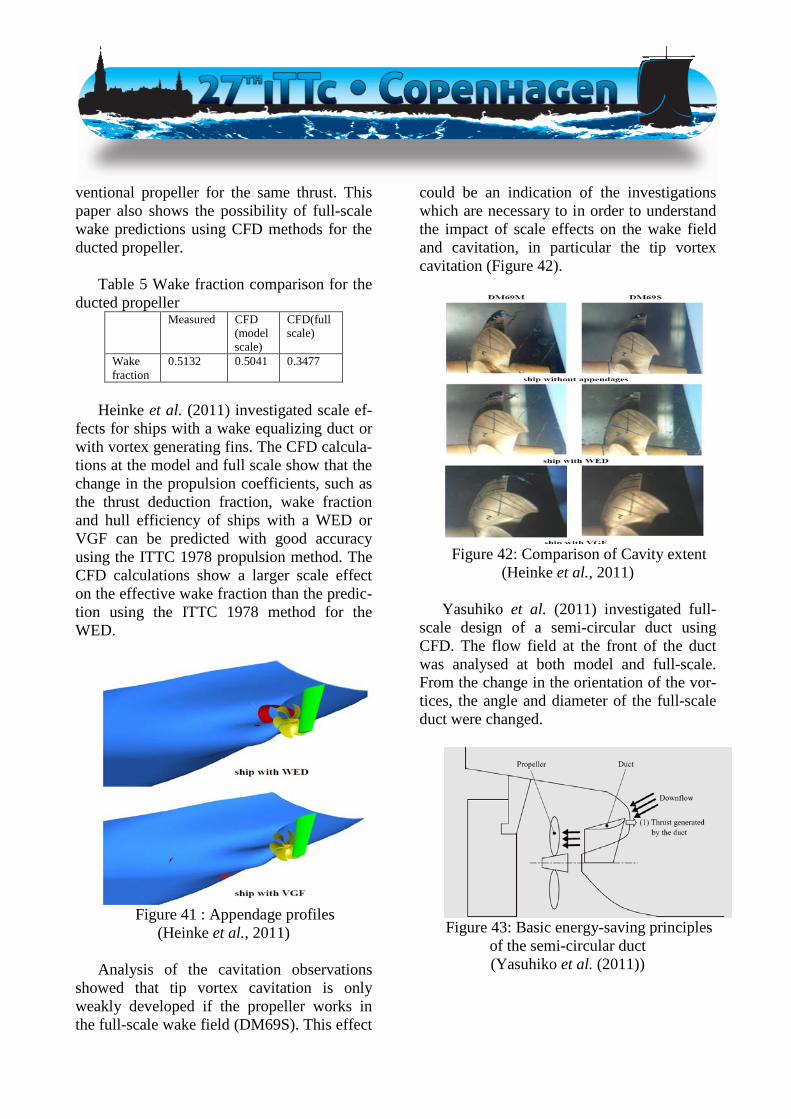
ventional propeller for the same thrust. This paper also shows the possibility of full-scale wake predictions using CFD methods for the ducted propeller.
Table 5 Wake fraction comparison for the
ducted propeller Measured CFD
(model scale)
CFD(full scale)
Wake fraction
0.5132 0.5041 0.3477
Heinke et al. (2011) investigated scale ef-
fects for ships with a wake equalizing duct or with vortex generating fins. The CFD calcula-tions at the model and full scale show that the change in the propulsion coefficients, such as the thrust deduction fraction, wake fraction and hull efficiency of ships with a WED or VGF can be predicted with good accuracy using the ITTC 1978 propulsion method. The CFD calculations show a larger scale effect on the effective wake fraction than the predic-tion using the ITTC 1978 method for the WED.
Figure 41 : Appendage profiles
(Heinke et al., 2011) Analysis of the cavitation observations
showed that tip vortex cavitation is only weakly developed if the propeller works in the full-scale wake field (DM69S). This effect
could be an indication of the investigations which are necessary to in order to understand the impact of scale effects on the wake field and cavitation, in particular the tip vortex cavitation (Figure 42).
Figure 42: Comparison of Cavity extent
(Heinke et al., 2011) Yasuhiko et al. (2011) investigated full-
scale design of a semi-circular duct using CFD. The flow field at the front of the duct was analysed at both model and full-scale. From the change in the orientation of the vor-tices, the angle and diameter of the full-scale duct were changed.
Figure 43: Basic energy-saving principles
of the semi-circular duct (Yasuhiko et al. (2011))
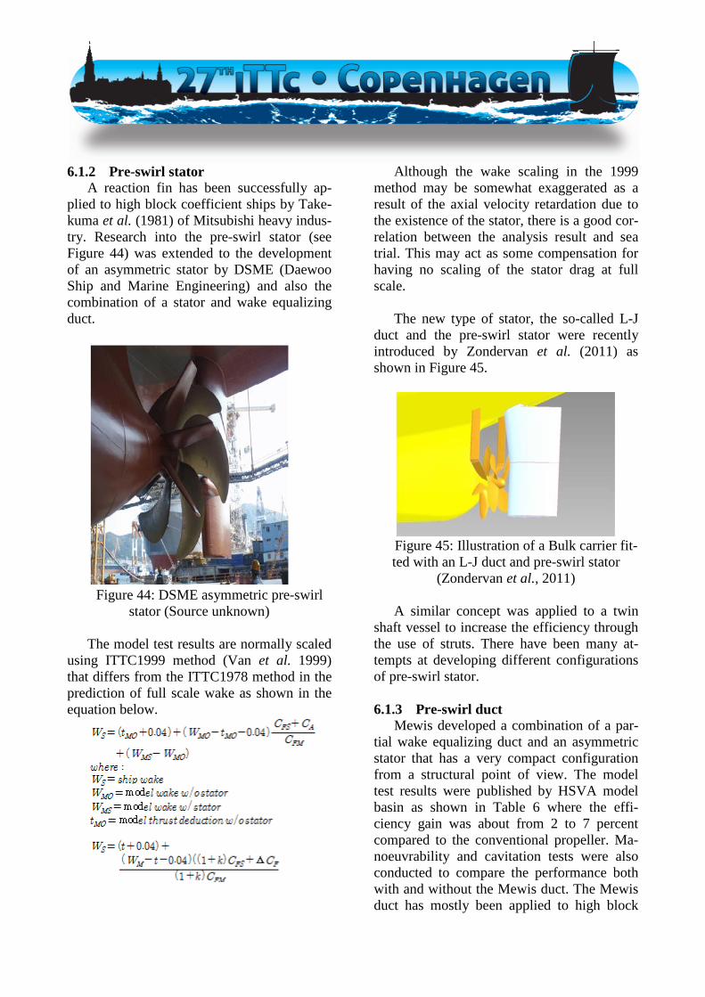
6.1.2 Pre-swirl stator A reaction fin has been successfully ap-
plied to high block coefficient ships by Take-kuma et al. (1981) of Mitsubishi heavy indus-try. Research into the pre-swirl stator (see Figure 44) was extended to the development of an asymmetric stator by DSME (Daewoo Ship and Marine Engineering) and also the combination of a stator and wake equalizing duct.
Figure 44: DSME asymmetric pre-swirl
stator (Source unknown) The model test results are normally scaled
using ITTC1999 method (Van et al. 1999) that differs from the ITTC1978 method in the prediction of full scale wake as shown in the equation below.
Although the wake scaling in the 1999 method may be somewhat exaggerated as a result of the axial velocity retardation due to the existence of the stator, there is a good cor-relation between the analysis result and sea trial. This may act as some compensation for having no scaling of the stator drag at full scale.
The new type of stator, the so-called L-J
duct and the pre-swirl stator were recently introduced by Zondervan et al. (2011) as shown in Figure 45.
Figure 45: Illustration of a Bulk carrier fit-ted with an L-J duct and pre-swirl stator
(Zondervan et al., 2011) A similar concept was applied to a twin
shaft vessel to increase the efficiency through the use of struts. There have been many at-tempts at developing different configurations of pre-swirl stator.
6.1.3 Pre-swirl duct
Mewis developed a combination of a par-tial wake equalizing duct and an asymmetric stator that has a very compact configuration from a structural point of view. The model test results were published by HSVA model basin as shown in Table 6 where the effi-ciency gain was about from 2 to 7 percent compared to the conventional propeller. Ma-noeuvrability and cavitation tests were also conducted to compare the performance both with and without the Mewis duct. The Mewis duct has mostly been applied to high block

coefficient ships such as bulk carriers and tankers as the duct is more effective.
The pre-swirl duct was analysed with a
varying stator angle and angle of attack of the duct by Huang et al. (2012). The changes in the wake field were with the variation of pa-rameters in a pre-swirl duct. An efficiency gain of between 2.9% and 4.3% was calcu-lated using CFD computations of these varia-tions.
Guiard et al. (2013) proposed a full-scale
design for a pre-swirl duct through the use of a CFD code. It was stated that a complicated turbulence model is difficult to apply to a compound propulsor such as a Mewis duct. The computed results are expected to be vali-dated by full-scale test data.
Table 6: Model test results with a BMS Mewis Duct from HSVA (Hollenbach and Reinholz, 2011) Year Ship
Type Gain in Power
Design Draught
Ballast Draught
2011 151k DWT Tanker
4.7% Not inves-tigated
2010 75k DWT Tanker
3.9% 7.2%
2010 163k DWT Tanker
4.7% 7.1%
2010 158k DWT Tanker
3.8% Not inves-tigated
2010 57k DWT Tanker
5.4% 7.8%
2010 20,000 DWT MPC
1.5% Not inves-tigated
2009 45k DWT Bulker
6.0% 5.4% *
2008 12,000 DWT MPC
7.7% 7.4%
2008 Aframax Bulk Carrier
6.9% Not inves-tigated
* light loaded draught condition
6.2 Devices at the propeller
6.2.1 Unconventional tip shape propellers Sistemar Company has proposed the Tip
Vortex Free propeller (TVF), though the name has subsequently been changed to the Contracted Loaded Tip propeller (CLT). The concept behind the design is the same as for a winglet on an airplane. This idea has been ex-

tended to both forward (so called KAPPEL) and backward smoothly curved tip rake pro-pellers to mitigate cavitation risks at the pro-peller tip. The reduced strength of the tip vor-tex reduces the pressure fluctuations on the hull surface rather than improving the effi-ciency. The backward tip rake propeller has been applied to most propellers in Korean ship-yards recently.
Anderson (1997) reported three kinds of
extrapolation for tip fins, using a method based on the ITTC78 method. To secure a fair comparison, this procedure was applied to both the tip fin and conventional propellers. The corrections turned out to be bigger for the tip fin propeller, meaning that it is more sensi-tive to scale effects. Unfortunately, no full-scale tests have been undertaken and so no confirmation of this scaling procedure can be made.
Inuakai (2013) conducted a comparative
study on the performance of backward and forward (KAPPEL type) tip rake propellers. It was found that the negative pressure area on the blade can be significantly reduced with backward tip rake propellers. This means that the blade area can be reduced without sacri-ficing cavitation performance, which conse-quently leads to a 2.6% higher efficiency when compared with a conventional propel-ler.
Figure 46: Forward tip rake propeller
(Source unknown)
Figure 47: Backward tip rake propeller
(Source unknown)
Figure 48: Contracted loaded tip propeller
(Source unknown) Bertetta (2012) carried out EFD and CFD
work to analyse the CLT propeller. A panel method and RANS code were used in the computational analysis of the POW perform-

ance and cavitation. There was good agree-ment between the experiments and computa-tions, with an overall error of less than 4%.
Inukai (2011) proposed the concept of a
CRP with a tip rake propeller to improve the propulsive efficiency. The efficiency of the backward tip rake type is slightly better than that of the forward type but there was no gain found in the experiment. Ultimately, a 1.5% efficiency gain was found compared to a con-ventional CRP.
Sanchez-Caja et al. (2012) analysed the
scale effects of the CLT propeller using CFD (RANS Solver). According to their computa-tional results, the difference between the full and model scale is larger than for a conven-tional propeller because the flow separation area is somewhat larger than that of a conven-tional propeller. This means that the standard extrapolation method for a conventional pro-peller may not be applicable to a CLT type propeller.
Cheng et al. (2010) reported on the scale
effects for an end plate effect propeller (KAPPEL) using both numerical computa-tions and experiments. The CFD showed lar-ger scale effect for both thrust and torque as compared with EFD, which only showed scale effect on torque.
Nielson et al. (2012) proposed a combined
system of a KAPPEL propeller and rudder bulb whose efficiency was up to 9% higher than a conventional propeller system. The proportion of this gain from the KAPPEL propeller and rudder bulb were almost even.
Figure 49: Comparison of cavity extent using panel and RANSE numerical computations (Cheng et al., 2010)
Figure 50: Open water propeller
characteristics from RANS / Panel method / Experiments at the model scale
(Nielson et al., 2012)

Figure 51: Pressure distribution and
streamlines for a KAPPEL propeller with a rudder bulb seen from starboard and port
sides (Nielson et al., 2012)
6.2.2 Propeller Boss Cap Fins (PBCF)
The PBCF is a relatively compact and cheap energy saving device. The effects of which are related to the propeller’s radial loading distribution. If the loading around the hub region is large, the rotational energy of the hub vortex can be effectively recovered by the PBCF.
Ouchi (1989) reported the comparative
analyses of the sea trial results of 11 ships and their models. The results indicated consider-able scale effects between the model and ac-tual measurements, such that the efficiency gain at full scale could be two to three times that at the model scale. As far as extrapolation methods are concerned, no dedicated proce-dure for the PBCF has been reported.
Kawamura et al. (2012) reported the dif-
ference between the effects of PBCF in model tests and in the full-scale data using CFD computations. The efficiency of the computed full-scale value was better than the model test results by around 1%, however it was still al-most 2% smaller than the sea trial data.
Hansen et al. (2011) reported the analysed
results of the efficiency improvement from PBCF installation in more than 60 vessels. Improvements in efficiency of between 2% and 10% were shown, with an average im-provement of 5%. Full-scale tests were car-ried out to find the correlation between the model and full scale results. The full scale results, showing an efficiency gain of around 4%, were a slightly less than the model test results which indicate that no large scale ef-fect is present which is a different conclusion from Ouch (1989). The hull condition was also examined to assess the full-scale results sensitivity.
Figure 52: Re Relationship between M/E output and FOC saving using PBCF
(Hansen et al., 2011)

Figure 53: Fitting the PBCF to a full scale
ship (Hansen et al., 2011) Hsin et al. (2011) has carried out compu-
tations on the unsteady forces in contra-rotating propellers using RANS code and the BEM method. Two CRPs were chosen to be examined and the experimental results were compared. Overall there was a reasonable cor-respondence between the two, except for the torque of the aft-propeller
6.2.3 Rim driven
Yakovlev et al. (2011) compared the rim driven propeller of both the hub and hubless types. The thrust and torque of the hubless propeller are higher than those of the propel-ler with the hub, whilst the efficiency is al-most same. Qing-ming et al. (2011) investi-gated the rim driven propeller (hubless pro-peller) with four different pitch distributions to examine the performance variations. It was shown that the vortex at the hub is closely re-lated to the radial loading distribution of the propeller.
Cao et al. (2012) designed and analysed a
rim driven thruster using a CFD code coupled with lifting line theory. The computed results have a good correlation with the experimental data. The computed results also indicated that the correct adjustment of the blade loading distribution can restrain the root and the tip region vortex.
Figure 54: Rim driven propeller
(Superyacht News.com, 2011)
6.3 Devices behind the propeller The most well-known device which can be
located behind the propeller may be the Grimse vane wheel, whose efficiency is known to be around 6%. This device however has been used only reluctantly recently as a result of the possibility of damage due to the free running condition and its large diameter.
Figure 55: Grim vane wheel
(Source unknown) Unconventional rudders have recently
been the focus for energy savings as well as for the reduction of cavitation problems on the rudder surface. Additional thruster fins (including a post-swirl stator) and a rudder-bulb (including a costa bulb) have been fur-ther developed. As the bulb size increases, the efficiency of the propeller can also be higher due to the smaller contraction of the slip stream caused by the rudder bulb. There have

been very few studies recently into devices located behind the propeller, which may be due to the complex flow pattern at the stern.
Figure 56: Thrust fin
(Hyundai heavy industry)
Figure 57: Rudder bulb
(Rolls-Royce brochure)
6.4 Oscillating propulsor. Mattheijssens et al. (2012) reported the
analysis of an oscillating foil with a combined motion of heaving and pitching from experi-ments and a numerical approach. The effi-ciency of the passive horizontal foil is very high at the design frequency and half of one chord length depth.
Politis and Tsarsitalidis (2012) reported
the Flexible Oscillating Duct as a novel pro-pulsor. BEM theory was used for the theoreti-cal analysis of this propulsor and the effi-
ciency gain obtained was between 3% and 10% when compared to a B-series propeller.
7 EXAMINE METHODS OF WAKE SIMULATION
For cavitation tests and measurements of
hull pressure fluctuations, the correct simula-tion of the full-scale wake field is an impor-tant technique for the reduction of scale ef-fects. One possible solution is to use a model that does not have complete geometrical simi-larity but is shaped to produce the full-scale wake field. In this case, the full-scale wake field is calculated by the use of CFD tools. Such models are often called “smart dummy” models.
In Germany the joint research project
KonKav II, “Correlation of Cavitation Effects Under Consideration of the Wake Field” has been initiated. Participants are Flensburger Schiffbau-Gesellschaft (FSG), Hamburgische Schiffbau-Versuchsanstalt (HSVA), Schiff-bau-Versuchsanstalt Potsdam (SVA), Techni-sche Universität Hamburg-Harburg (TUHH) and Universität Rostock (UniHRO). The pur-pose of the research project KonKav II is to develop a more accurate and marketable cavi-tation prognosis. In the project the focus is on scale effects that occur through the interaction between wake field, propeller cavitation and the resulting pressure fluctuations. A deeper understanding of these processes will help to convert model test results to full-scale predic-tions in a reliable way.
One of the objectives is to improve simu-
lation of a full-scale wake field in the context of model tests. It is common practice to use dummy models with attached strainers influ-encing the flow in a way that the wake field of the full-scale version is simulated. A pro-cedure based on an adjoint sensitivity analysis has been developed by Technical University

Hamburg-Harburg to find appropriate dummy model geometry and appropriate mesh pa-rameters of the strainers to simulate the previ-ously calculated full scale wake field. The photographs (Figure 58) show the geometry of the additional grids used on the conven-tional dummy model and a dummy model that is optimised on the base of an adjoint sensitiv-ity analysis.
Figure 58: Additional wire grids for the
conventional dummy model (left) and the op-timised dummy model (right), Photograph from Schiffbau-Versuchsanstalt Potsdam This research project is on-going, and
more results will be available within the next committee.
Schuiling et al. 2011, Bosschers et al.
2012 and Johannsen et al. 2012 report the use of such smart dummy models. Simple short-ening and narrowing the model (Figure 59) did not lead to sufficient wake fields. Good results could be achieved by modifying the gondola only in a way that propeller clearance and shaft height was kept the same. The result is shown in Figure 60.
Figure 59: Examples of intermediate
forms in systematic hull form variations of width and length.
Figure 60: View from behind the Smart
Dummy design (left), and the original geosim hull (right)
Even though the full-scale wake field was
not fully represented, a good similarity in the upper part was achieved (Figure 61).
Figure 61: Axial wake velocities of the
Smart Dummy design (left) compared to those at ship scale (right). The dashed lines
are at 1.1 and 0.6 times propeller radius. The solid line is at the propeller radius

Blade rate order hull pressure fluctuations were close to those found on full scale, but higher order blade rate components were not improved with respect to the full scale. The resulting hull pressure fluctuations for a sen-sor directly above the propeller were com-pared. The full- scale measurements were made available by Lloyd’s Register. The geo-sim results were obtained using the wake peak identity approach while the smart dummy re-sults were obtained using thrust-identity. A very good agreement between model scale tests and full-scale tests was obtained for the first harmonic while for the second harmonics there is still a considerable difference.
Figure 62: Comparison of non-
dimensional full scale (in black) and model scale (in blue and green) pressure amplitudes
for first four blade rate orders. In Heinke, et al. (2011), the scale effects
on cavitation and fluctuating pressure were experimentally investigated for the cases of a container ship without and with the WED or the VGF fitted. Based on RANS simulations, a shortened dummy model was adopted to simulate the “full-scale wake”. In all the cases, the pressure pulses were found to be apparently lower in the “full-scale wake” than in the model wake. Either the WED or the VGF could further reduce the pressure pulses. However, the variations in the fluctuating pressure amplitudes with the attack angle of VGF were found to be different at model- and full-scale, which might provide some hint as to how to optimize the orientation of the VGF.
Further publications deal with adjoint
RANS for hull form optimisation, such as
Stück et al. (2010), Kröger et al. (2011), and Rung et al. (2012). Various objective func-tions are considered, among other things the wake quality. Further developments in this field could also be useful for an effective and fast design of smart dummy models.
8 WAKE FRACTION SCALING FOR TWIN SCREW SHIPS
This is related to the 1978 Performance
Prediction method in which no wake fraction scaling is given for twin skeg cases.
For cases of finer forms where the shaft is
supported by A-brackets using wTS = wTM is still advised and appears to be the general practice.
However, there is an increasing number of
fuller form twin skeg vessels. In these vessels the wake field experienced by the propeller is close to that of a single skeg vessel and it might be that the normal single screw wake-scaling procedure should be used. This proce-dure is used by several establishments.
The use of wake scaling on twin skeg
ships needs to be examined further and the next committee should seek to obtain exam-ples of model and ship data so that the issue of wake scaling can be examined. In particu-lar the issue of whether the full wake scaling as used in the single screw method or some reduced level of scaling should be used.
Ohmori et al. (2013) have studied the scal-
ing of results from a twin skeg model by CFD and by three semi-empirical techniques. They conclude that the method due to Tanaka gave the best result, but also that the axial and tan-gential components of wake may need to be scaled separately. They conclude that more work is needed on the scaling of tangential wake.

Sakamoto et al. (2011) used CFD backed
by model tests to examine wake scaling on twin skeg ships. The work suggests that the ITTC78 single screw scaling method gives reasonably good results, but further work to develop specific twin skeg wake scaling methods is suggested.
9 SCALING OF CONVENTIONAL AND UNCONVENTIONAL PRO-PELLER OPEN WATER DATA
For initiating a comparative CFD-
calculation project two propeller geometries that are in the open domain had to be found. For the conventional propeller the PPTC-propeller (Potsdam Propeller Test Case) from SVA Potsdam could be used. But geometry for an unconventional propeller could not be found.
The PPTC-propeller has 5 blades and a di-
ameter of 250 mm. The following test de-scription was given by the ITTC:
• The propeller shall be tested in a pull con-
figuration. The corresponding hub cap is provided.
• The extent of the shaft behind the propel-ler has to be at least two propeller diame-ters.
• The extent of the solution domain can be chosen arbitrarily, however it is consid-ered necessary to have a radial domain extent which gives a cross sectional area of the domain which is at least 100 times larger than the corresponding propeller disc area. Radial extent Ddomain > 10 DP
• The dimensionless wall distance on the propeller blade shall be chosen such that the viscous sublayer is resolved.
• It is highly recommended to conduct the calculations in model scale under consid-
eration of laminar-turbulent transition on the blade. For the full-scale calculations a fully turbulent inflow can be assumed.
• The calculations shall be carried out ne-glecting cavitation.
• The water characteristics shall be taken for a water temperature of Tw = 15°C as provided in Tab. 1 on page 2.1.
• The propeller is a controllable pitch pro-peller. The gap between hub and blade root is considered unimportant regarding the integral values of the propeller and shall not be taken into account.
• The decision to calculate a single blade passage or the entire propeller (5 blades) is left to the participant. With respect to the test results the follow-
ing evaluation was requested by the ITTC: • Two different scale ratios (λ = 12 and λ =
1). • Five different advance coefficients:
J = 0.6, 0.8, 1.0, 1,2 and 1.4 • The forces on the propeller blade and on
blade sections The thrust and torque of different blade
sections shall be evaluated. The coefficients shall be subdivided into a pressure and a fric-tional component. The intention is to obtain a deeper and more detailed insight into the scale effects of the propeller. The total thrust and torque is obtained via the summation of the different blade section values. The calcula-tions shall be conducted in model and full-scale.
In total 10 calculations were requested.
The results are not linked to the correspond-ing participant, guaranteeing anonymity.
All ITTC members were invited to par-
ticipate on the comparative CFD-calculation by email. On the SVA Potsdam web site

(www.sva-potsdam.de/pptc_ittc_switch.html) the propeller data, an Excel sheet for the re-sults and instructions for the calculations are provided.
In total 9 institutions participated at the
ITTC propeller benchmark. Some institutions provided multiple results, giving in total 12 results. The following the institutions partici-pated: • DGA Hydrodynamics • Hyundai Heavy Industries • Krylov State Research Centre • MARIC • SJTU • SSPA • SSSRI • SVA • Technical Research Centre Japan Marine
United Corporation (JMU) The computational results were evaluated
for the following: • Computational method, approach • Open water curves • Thrust and torque on blade sections
The participants were asked to fill out a
questionnaire and provide details regarding their computations. From this, the following can be drawn: • In general a single blade passage with pe-
riodic side boundaries is used • The side boundaries are in general match-
ing • In general unstructured meshes consisting
of tetrahedral elements with a prismatic boundary layer and local grid refinment are used
• In model scale the dimensionless wall distances ranges between 1 and approx. 50
• In full-scale the dimensionless wall dis-tances ranges in general between 1 and approx. 30
• The number of cells on the blade surface in the range between 9,800 and 80,000
• For the domain extent two groups can be distinguished. One keeping the domain very large with the cross sectional area of the domain being 3600 times as large as the propeller disc area. The other group has the domain extent very small having values of below 16. The same applies for the upstream and downstream extent of the solution domain.
• All participants use 2 equations turbu-lence models The calculated open water curves are
compared with the corresponding measure-ments. The measured model scale open water curves are extrapolated to full-scale according to the ITTC extrapolation method. The ex-trapolated model data is denoted as EFD (ex-perimental fluid dynamics) results. The CFD (computational fluid dynamics) and EFD re-sults are compared.
The thrust and torque generated by differ-
ent blade sections, ranging from the hub to the tip of the propeller, are investigated for the requested advance coefficients, both for model and full-scale. The following two dia-grams show the KT and KQ curves, for the model scale and as recalculated by the ITTC 78 method for ship scale, in comparison with CFD data for full scale. Whilst the KT correc-tion according to ITTC 78 method is very small, the CFD results show bigger correc-tions. For KQ the CFD results show positive corrections for higher advance coefficients. The standard deviation of ∆KT and ∆KQ is greater than the values itself. That may be

caused by the small size of the calculation set. Thus these diagrams are preliminary results. More calculations are necessary.
Figure 63: Mean CFD values with σ-bounds and comparison with open water curves in
model scale.
Figure 64: Mean CFD values with σ-bounds
and comparison with open water curves in full scale.
Figure 65: ∆KT, red acc. to ITTC 78, black
from CFD with σ-bounds.
Figure 66: ∆KQ, red acc. to ITTC 78, black from CFD with σ-bounds
Streckwall, et al. 2013 reported their work
on an advanced scaling procedure for marine propellers. Emphasis is put on propeller de-signs with blade shapes that differ from “con-ventional” type. The work was performed within the European project “PREFUL” with the target to investigate the possibilities of improvements of the scaling calculation in order to consider the differences between blade shapes more precisely. As a result the differences between the several scaling pro-cedures are shown, especially in comparison to the results of a new “strip method”, which was developed within the project. It is under-stood that the enhanced open water correc-tions are to be compared with full-scale ob-servations (trial trips) in future.
10 DEVELOP GUIDELINES FOR HY-BRID PROPULSOR TESTING
10.1 Purpose Social demand on energy saving and
greenhouse gas emission reduction is generat-ing pressure to develop new more efficient propulsors. Remarkable advances in hybrid propulsors (propulsion systems consisting of more than one type of propulsor) has been made in recent years. But the model testing

procedure for such propulsors systems has not yet been established.
Among several configurations of hybrid
propulsor, the committee focused on the Hy-brid Contra-Rotating Shaft Pod propulsor (HCRSP or so-called hybrid CRP concept) and has developed model open water and pro-pulsion test procedure guidelines.
10.2 Definition and Classification There exist many combinations of hybrid
propulsors. They can be classified into two major groups: low interaction group and high interaction group. The high interaction group consists of different propulsors arranged in line in fairly close proximity (e.g. CASE III of Table 1 in Paragraph 3). All other configu-rations (parallel or in line propulsors with more distance in between) are usually classi-fied into low interaction group (e.g. CASE II and IV of Table 1 in Paragraph 3).
As described in the new guideline, model
test of low interaction group can be conducted following the conventional Propulsion Test Procedure 7.5-02-03-01.1 or Podded Propul-sor Test Procedure 7.5-02-03-01.3 or Waterjet Propulsion Performance Prediction – Propul-sion Test and Extrapolation 7.5-02-05-03.1. However load-varying test should be con-ducted for each propulsor separately to deter-mine the self-propulsion point.
10.3 Description of guideline A guideline for the high interaction case
was developed. Although many combinations of propulsor (e.g. conventional propeller, POD, waterjet, Z-drive, CRP and so on) are possible, effective combinations from the viewpoint of energy efficiency are limited. Thus the guideline focuses on the one of the
more significant combinations, HCRSP pro-pulsors. The method is based on the studies by Sasaki (2006/2009), Chang (2011), Quereda (2012), and Sánchez-Caja (2013).
The tank model test consists of propulsor
open water test, resistance test and self-propulsion test. The unique point of hybrid propulsor model test is that load distribution between fore propeller and aft POD is not fixed. Thus the load distribution varying tests are compulsory in both propulsor open test and self-propulsion test.
Another point is the arrangement of the
propeller open boat for the fore conventional propeller. As for the aft POD drive located behind the fore propeller, the propeller open boat must be arranged in reversed configura-tion (in front of the fore propeller). In the re-versed configuration, viscous wake of the propeller open boat flows into the propeller and the measured results are to be appropri-ately corrected (Ohmori, 2013).
Fore Prop.
FLOW
Propeller Open Boat
POD dynamometer
Aft Prop.
Figure 67: Open water test configuration
The final guideline is registered as 7.5-02-03-01.6 Hybrid Contra-Rotating Shaft Pod Propulsors Model Test.
10.4 Discussion The procedure covers only model tests and
the scaling method is not included. The rea-son for this is the lack of full-scale validation data. Although the scaling method for podded propulsors will be helpful, the development of the full-scale prediction method is the subject of future work.

Mitsubishi Heavy Industries (MHI) is the first shipyard that has built a large ship with HCRSP (Ueda, 2004). Their tank test proce-dure is simpler than the new guideline (it is basically based on the conventional propulsor test procedure), but it has already been con-firmed by the full scale trial results. However the committee could not adopt this method as no published paper is available.
Figure 68: HCRSP mounted on a ROPAX
Ferry (Ueda, 2004)
11 MONITORING OF FULL SCALE DATA FOR PODDED PROPULSION.
No new full-scale data has been published,
the only known available example is the “ABB case”. The Propulsion committee con-tacted ABB to establish if such data could be published.
The discussion in the 25th ITTC POD
committee report concluded that the main is-sue is still the scaling of pod housing drag. Taking this into account, the most helpful re-sults for benchmarking would be full-scale data with measurements of propeller thrust, torque and also pod housing drag.
The propulsion committee, with reference
to Honninen, et al. (2007), discussed with ABB if such full-scale data could be made available for the ship “Norilsky Nickel” for which extensive full-scale measurements were
conducted, including simultaneous measure-ments of the loads on the thruster body and propeller. ABB express its willingness to ac-quire and analyze such data and to publish the results in future.
12 CONCLUSIONS
12.1 Recommendations to the Next Com-mittee
12.1.1 Procedure Review/Update
The 27th Propulsion committee has devel-oped a new guideline for HCRSP (Hybrid Contra-Rotating Shaft Pod) Propulsor Model Tests. The model test scaling is not discussed in this guideline as there is a lack of model test and full-scale trials comparison data. For this reason, the committee recommends the continued monitoring of model test and scal-ing procedures used for this kind of device (and for propulsion devices in general) by member institutions of the ITTC. If there is sufficient information on the comparison be-tween model and full scale data indicating changes to test or scaling procedures, the rel-evant guidelines should be updated.
The committee recommends that the mon-
itoring of the existing literature for examples of the Reynolds number scale effects should continue in order to update the 7.5-02 -05-03.2 Waterjet System Performance procedure. Clarification and detailing of the procedure in the part relating to the data acquisition and in the part related to extrapolation is required. Further reviews of the literature should exam-ine the need and use of the blade-tip and chord Reynolds numbers as well the intake duct Reynolds number and update the proce-dure if required.
The committee recommends a review of
the power margins given in the guidelines and

the monitoring of the effect of the introduc-tion of the EEDI on power margins.
12.1.2 New Procedures
The committee recommends developing a new procedure for propulsion performance prediction for triple shaft vessels. Although the existing procedure largely covers this, the procedure needs to be extended to take ac-count of the interaction between centerline and wing propulsors and to allow for the de-termination of the wake fraction and the thrust deduction factors for these propulsors sepa-rately.
12.1.3 Technologies to Monitor
The committee recommends monitoring the model test and scaling procedures for en-ergy saving device technologies. The impact on self-propulsion and cavitation testing is also to be reported to assess the way of taking into account differences in inflow speed and direction between the model and the ship. This is particularly relevant to wake improv-ing devices where the optimum alignment may be different between the model and ship. This raises the question of the relevance of any propulsive gains determined from model tests to the ship. The use of CFD and/or a combination of CFD and EFD should be also considered, as well as full-scale trials results.
The committee recommends monitoring
the “smart dummy” model used for cavitation tests for propulsors behind a skeg. A joint re-search project “Koncav II” has been launched in Germany and preliminary results might be available within the three years term of the next committee.
The committee recommends examining
the existing procedures and assessing where CFD results can be introduced in the propul-sion process to assist EFD e.g. use CFD to determine the target wake field to be modelled in cavitation testing, use of smart dummy model
to model the target wake field, use of CFD in conjunction with EFD for composite propel-lers).
The present committee was not able to
find a suitable model test and CFD study for unconventional propellers. The definition of what would be interesting to work with as an unconventional propulsor is still to be dis-cussed with the CFD committee.
Recent publications suggest that RANS
codes are more and more widely used for propulsor design. The analysis of the data of the benchmark launched by the 27th commit-tee should be able to give some answers to the use and interpretation of RANS methods and procedures. A combine effort with the CFD committee will encourage the continuation of this study with the aim of getting further con-tributions from member institutes. The EFD data used in this study comes from only one institute. The committee recommends that ad-ditional EFD studies on the same propeller design should be performed.
An area to examine is the fluctuating
components of propeller bearing forces, espe-cially on Pod and azimuthing thruster
Further work is still required on the way to
test and analyse the results for composite pro-pellers. The use of CFD in combination with EFD to investigate the fluid-structure interac-tion (static and dynamic hydro-elastic re-sponse) needs to be better understood.
Experimental techniques such as detailed
local flow velocity measurement using PIV, blade strain, cavity surface and volume meas-urement still need to be monitored.
Testing and estimation methods for
propulsors in bubbly flow should be moni-tored. The open-water and self-propulsion characteristics in bubbly flow are relevant to

air lubricated vessels and the effect of void fraction, void type and affected area on the propeller need to be investigated and under-stood.
12.1.4 Scaling for Propulsors
As no full scale data on Pod Propulsor have been found within this session, the committee recommends that the next commit-tee should continue to look for-full scale data.
The prediction of full scale cavitation in-
duced hull pressure is still of interest either by means of CFD directly or CFD and EFD used in combination.
In view of the growing interest in energy
saving devices further work is still required on model test techniques and the prediction of power savings.
12.2 Recommendations to the Conference The Committee recommends to the Full
Conference that they should • Adopt the revised procedure ITTC Proce-
dure 7.5-02 03-01.4 1978 ITTC Perfor-mance Prediction Method
• Adopt the revised procedure ITTC Proce-dure 7.5-02 03-02.3 Propulsor Nominal Wake Measurement by LDV Model Scale Experiments
• Adopt the revised procedure ITTC Proce-dure 7.5-02 03-03.2 Testing and extrapo-lation Methods Propulsion : Cavitation Description of Cavitation Appearances
• Adopt the revised procedure Update to ITTC Procedure 7.5-02 03-03.3 Cavita-tion Induced Pressure Fluctuations Model Scale experiments
• Adopt the revised procedure ITTC Proce-dure 7.5-02-03-03.4 Cavitation Induced Pressure Fluctuations: Numerical Predic-tion Methods
• Adopt the new guideline 7.5-02-03-01.6 HCRSP (Hybrid Contra-Rotating Shaft Pod) Propulsors Model Test
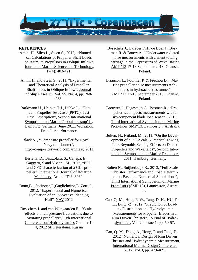
REFERENCES Amini H., Sileo L., Steen S., 2012, “Numeri-
cal Calculations of Propeller Shaft Loads on Azimuth Propulsors in Oblique Inflow”, Journal of Marine Science and Technology,
17(4): 403-421.
Amini H. and Steen S., 2011, “Experimental and Theoretical Analysis of Propeller
Shaft Loads in Oblique Inflow”, Journal of Ship Research, Vol. 55, No. 4, pp. 268-
288.
Barkmann U., Heinke H.J., Lübke L., “Pots-dam Propeller Test Case (PPTC), Test
Case Description”, Second International Symposium on Marine Propulsors smp’11, Hamburg, Germany, June 2011, Workshop:
Propeller performance
Black S. , “Composite propeller for Royal Navy minehunter”,
http://compositesworld.com/articles/, 2011.
Bertetta, D., Brizzolara, S., Canepa, E., Gaggero, S and Viviani, M., 2012, “EFD and CFD characterization of a CLT pro-peller”, International Journal of Rotating
Machinery, Article ID 348939.
Bono,B., Cucinotta,F.,Guglielmino,E.,Zotti,I., 2012, “Experimental and Numerical Evaluation of an Innovative Planning
Hull”, NAV 2012
Bosschers J. and van Wijngaarden E., "Scale effects on hull pressure fluctuations due to cavitating propellers", 10th International
Conference on Hydrodynamics October 1-4, 2012 St. Petersburg, Russia
Bosschers J., Lafeber F.H., de Boer J., Bos-man R. & Bouvy A., “Underwater radiated noise measurements with a silent towing
carriage in the Depressurized Wave Basin”, AMT ’13 17-18 September 2013, Gdansk,
Poland.
Briançon L., Fournier P. & Frechou D., “Ma-rine propeller noise measurements tech-
niques in hydroacoustics tunnel”, AMT ’13 17-18 September 2013, Gdansk,
Poland.
Brouwer J., Hagesteijn G., Bosman R., “Pro-peller-ice impacts measurements with a
six-component blade load sensor”, 2013, Third International Symposium on Marine Propulsors SMP’13, Launceston, Australia.
Bulten, N., Nijland, M., 2011, “On the Devel-
opment of a Full-Scale Numerical Towing Tank Reynolds Scaling Effects on Ducted Propellers and Wakefields”, Second Inter-national Symposium on Marine Propulsors
2011, Hamburg, Germany.
Bulten N., Suijkerbuijk R., 2013, “Full Scale Thruster Performance and Load Determi-nation Based on Numerical Simulations”, Third International Symposium on Marine Propulsors (SMP’13), Launceston, Austra-
lia.
Cao, Q.-M., Hong F.-W., Tang, D.-H., HU, F.-L., Lu, L.-Z., 2012, “Prediction of Load-
ing Distribution and Hydrodynamic Measurements for Propeller Blades in a
Rim Driven Thruster”, Journal of Hydro-dynamics, Vol. 24, Issue 1, pp. 50-57.
Cao, Q.-M., Dong, A., Hong, F. and Tang, D.,
2012 “Numerical Design of Rim Driven Thruster and Hydrodynamic Measurement, International Marine Design Conference
2012, Vol 3, pp. 479-489.

Carlton, J. S., 2012, “Marine propellers and propulsion”, Butterworth Heinemann,
Great Britain.
Castro A. M., Carrica P. M., Stern F., 2011, “Full scale self-propulsion computations using discretized propeller for the KRISO container ship KCS”, Computers & Fluids,
51, pp.35~47.
Chang, S.-H., Kinnas, A., 2012, “Numerical Simulation of Wetted and Cavitating
Flows inside Water-jets”, 29th Symposium on Naval Hydrodynamics, Gothenburg,
Sweden
Chang, B-J., Go, S., 2011, “Study on a proce-dure for propulsive performance predic-
tion for CRP-POD systems”, J. Marine Sci. Technology, Vol. 16 pp.1-7.
Cheng, H., Chien, Y., Hsin, C., Chang, K.,
Chen, P., 2010, “A numerical comparison of end-plate effect propellers and conven-tional propellers”, 9th International Con-ference on Hydrodynamics 2010, Shang-
hai, China, pp.495-500
Dang J., Liu R., Pouw C.,2012,”Waterjet Sys-tem Performance and Cavitation Test Pro-cedures”, Symposium on Marine Propul-
sors SMP’13,Launceston,Australia.
Dang J., Brouwer J., Bosman R. and Pouw C., 2012, “Quasi-Steady Two-Quadrant Open Water Tests for the Wageningen Propeller C- and D-Series”, Twenty-Ninth Sympo-sium on Naval Hydrodynamics, Gothen-
burg, Sweden.
Dang,J., van den Boom, H.J.J., Ligtelijn, J.Th.,2013, The Wageningen C- and D-
Series propellers, FAST ‘13
Delaney, K.,2011, “Use of RANS for analysis of a high speed Sealift Concept Vessel,
MARINE 2011,Lisbon,Portugal
DNV, 2010, “Rules for Classification Of Ships, Silent Class Notation”, Part 6,
Chapter 24. Det Norske Veritas.
Dubbioso G., Muscari R., Di Mascio A., 2013, “CFD Analysis of Propeller Performance
in Oblique Flow”, Third International Symposium on Marine Propulsors (SMP’13), Launceston, Australia.
Epps.Dual Operating point Blade optimiza-
tion for high speed propellers. FAST 2011
Eslamdoost, A., Larsson, L., Bensow, R.,2013, “Contribution of Different Parameters to the Thrust Deduction of a Waterjet Pro-
pelled Hull”, FAST 2013
Ferrieri J.M., Veitch B., and Akinturk A.,”Experimental Study on Ice Manage-
ment through the use of Podded Propeller Wash”, Third International Symposium on Marine Propulsors SMP’13, Launceston,
Australia May 2013.
Fujisawa T., 2013, “Study of Scale Effect on CRP by viscous CFD”, Conference Proc.
JASNAOE, 17: 147-148.
Funeno I., Pouw C., Bosman R, “Measure-ments and Computations for Blade Spin-dle Torque of Controllable Pitch Propel-lers in Open Water”, Third International
Symposium on Marine Propulsors SMP’13, Launceston, Australia May 2013.
Fu. Measurements and Computational Predic-
tions of a Deep-V MonohullPlaning Hull FAST 2011

Gany, A., Shemer,A., Gofer,A., Har-Lev,D., 2008, “Testing Air-Augmented Waterjet
Propulsion”, International Conference on Waterjet Propulsion, London, UK
Giles W., Dinham-Peren T., Amaratunga S.,
Vrijdag A., Partridge R., “The Advanced WaterJet: Propulsor Performance and Ef-fect on Ship Design”, 10th IMarEST Na-
val Engineering and Exhibition , May 2010, Portsmouth, UK
Głodowski R., Richards J., Koushan K.,
Alterskjaer S.A., Atlar M. & Saisto I., “Open water performance characteristics of a pod propulsor– the benchmark test”, The 3rd International Conference on Ad-vanced Model Measurement Technology for the EU Maritime Industry, AMT’13,
Gdansk, Poland.
Gowing S., 2011, “Experimental Study of an Air-Augmented Waterjetpropulsor”, Sym-posium on Marine Propulsors’11, Ham-
burg, Germany
Guiard, T., Leonard, S. and Mewis F., “The Becker Mewis Duct-Challenges in Full-Scale Design and new Developments for
Fast Ships”, 2013, Third International Symposium on Marine Propulsors
SMP ’13, Tasmania, Australia.
Haimov H., Vicario J., Del Corral, J., 2011, “RANSE Code Application for Ducted
and Endplate Propellers in Open Water”, Second International Symposium on Ma-rine Propulsors SMP’11, Hamburg, Ger-
many.
Hansen, H. R., Dinham-Peren, T., Nojiri, T., 2011, “Model and Full Scale Evaluation of a ‘Propeller Boss Cap Fins’Device Fitted to an Aframax Tanker”, Second Interna-tional Symposium on Marine Propulsors
2011, Hamburg, Germany.
Heinke H.-J., Hellwig-Rieck K., 2011, “Inves-tigation of Scale Effects on Ships with a
Wake Equalizing Duct or with Vortex Generator Fins”, Second International
Symposium on Marine Propulsors SMP’11, Hamburg, Germany.
He X.D., Hong Y., Wang R.G., “Hydroelastic
optimization of a composite marine pro-peller in a non-uniform wake”, Ocean En-
gineering Journal 39 (2012) 14–23.
Henderson K, “New Design of 2000 TEU Feeder“,
http://articles.maritimepropulsion.com/article/New-Design-of-2000-TEU-Feeder-
6784.aspx, Maritime propulsion, January 2012.
Hideki Y., Hiroaki M., Aiichiro Saeki, 2011, “Energy Saving Technology of the Diesel-Electric Propulsion, System for Japanese
Coastal Vessels”, IHI Engineering Review, Vol 44
Himei K. Numerical Analysis of Unsteady
Open Water Characteristics of Surface piercing Propeller. Third International
Symposium on Marine Propulsors SMP’13, Launceston,Australia
Hollenbach, U. and Reinholz, O., 2011, “Hy-
drodynamics Trends in Optimization Pro-pulsion”, Second International Sympo-sium on Marine Propulsors SMP’11,
Hamburg, Germany
Holtrop J., 2000, “MARIN Training Course on Propulsion Hydrodynamics”, Nether-
lands.
Huang S.-F., Huang G.-F., 2012, “Numerical Investigation for Effectiveness of Wake
Equalizing Duct”, 10th International Con-ference on Hydrodynamics, St. Petersburg,
Russia.

Huang, S., Huang, Z., Branch, S., 2012,” In-vestigation on Energy-Saving Effective-ness of Pre-Swirl Duct Based on CFD”, 10th International Conference on Hydro-
dynamics, St. Petersburg, Russia
Hur J. W., Lee H., Chang B. J., 2011, “Propel-ler Loads of Large Commercial Vessels at Crash Stop”, Second International Sympo-
sium on Marine Propulsors (SMP’11), Hamburg, Germany.
Hwang, J-L.,Chin, S-S.,Chang,K-K., Tu,
Chin-Chin.,2011, “Development of the Trans-Velocity Propellers”, Second Inter-
national Symposium on Marine Propulsors SMP’11, Hamburg, Germany
Inukai, Y., 2011, “Development of Contra-
Rotating Propeller with Tip-Raked Fins”, Second International Symposium on Ma-rine Propulsors SMP’11, Hamburg, Ger-
many.
Inukai, Y., “A Development of a Propeller with Backward Tip Rake Fin”, 2013,
Third International Symposium on Marine Propulsion SMP’13, Tasmania, Australia.
Ishida, S., Fujino, R., 1998, “A Performance
Prediction Method for Contra-rotating Propeller Ships”, Society of Naval Archi-tects of Japan, Vol. 183, pp. 35-44, 1998
(in Japanese).
Jang H., Mahesh, K., 2012, “Large Eddy Simulation of Crashback in Ducted Pro-pellers with Stator Blades”, 29th Sympo-sium on Naval Hydrodynamics, Gothen-
burg, Sweden.
Jang H., Mahesh, K., 2013, “Large Eddy Simulation of Flow around a Reverse Ro-
tating Propeller”, Journal of Fluid Me-chanics, 729: 151-179.
Johannsen, C., Wijngaarden, E., 2012, “Inves-tigation of Hull Pressure Pulses, Making Use of Two Large Scale Cavitation Test Facilities”, Proceedings of the Eighth In-
ternational Symposium on Cavitation (CAV 2012)
Jang, Jin-Yul, 2013, “Study on Performance
of Contra-Rotating Propeller”, 2013, Mas-ter Thesis, Pusan National University, Ko-
rea.
Kandasamy. Optimization of Waterjet Pro-pelled High Speed Ships – JHSS and Delft
Catamaran. FAST 2011
Kane C., http://www.compositecarbonfiberprop.com/qinetiq.htm, “World's Largest Compos-
ite Carbon Fiber Propeller”, 2001
Kawakita C., “Study on Marine Propeller Running in Bubbly Flow”, Third Interna-tional Symposium on Marine Propulsors
SMP’13, Launceston, Australia May 2013.
Kawakita, C., Takano, S., Kodan, Y., & Mizo-kami, S., (2011) ‘Experimental Investiga-tion of the Behavior of Injected Air on the Ship Bottom and its Influence on Propel-
ler’. Journal of the Japan Society of Naval, Architects and Ocean Engineers, Vol.12,
pp.43-50.
Kawamura, T., Ouchi, K., Nojiri, T., 2012, “Model and full scale CFD analysis of
propeller boss cap fins (PBCF)”, Journal of Marine Science and Technology, 0948-
4280.
Kawamura T., Ouchi K., Takeuchi S., 2013, “Model and full scale CFD analysis of
propeller boss cap fins (PBCF)”, Third In-ternational Symposium on Marine Propul-
sors SMP’13, Launceston, Australia.

Kim K.-S., Kim Y.-C., Kim J., Lee Y.-Y., Ahn H., Yim G., Park I.-R., 2012, “A Study on
the Energy Saving Fin Attached on the Ship Stern”, 10th International Conference on Hydrodynamics, St. Petersburg, Russia.
Kim, S.-E., 2009, “A Numerical Study of Un-
steady Cavitation on a Hydrofoil”, Proc., 7th International. Symposium on Cavita-
tion CAV2009, Ann Arbor, Michigan, USA.
Kinnas S.A., Jeon C.-H., Purohit J., TianY., 2013, “Prediction of the Unsteady Cavitat-
ing Performance of Ducted Propellers Subject to an Inclined Inflow”, Third In-
ternational Symposium on Marine Propul-sors SMP’13, Launceston, Australia.
Korkut, E., 2006, “A Case Study for the Ef-
fect of a Flow Improvement Device (a Wake Equalizing Duct) on Ship Powering
Characteristics”, Ocean Engineering, Vol.33, pp.205-218
Koushan K., Spence S., Savio L., 2011, “Ven-
tilated Propeller Blade Loadings and Spindle Moment of a Thruster in Calm
Water and Waves”, Second International Symposium on Marine Propulsors
SMP’11, Hamburg, Germany.
Krasilnikov V. I., 2013, “Self-Propulsion RANS Computations with a Single-Screw Container Ship”, Third International Sym-
posium on Marine Propulsors SMP’13, Launceston, Australia.
Li, D-Q, Grekula,M., Lindell, P. and
Hallander., J. (2012). Prediction of Cavita-tion for the INSEAN Propeller E779A Operating in Uniform Flow and Non-
Uniform Wakes. Proceedings of 8th Inter-national Symposium on Cavitation,
CAV2012, Singapore.
Lu, N. Svennberg,N., Bark, G. and Bensow, R. (2012) Numerical Simulations of the
Cavitating Flow on a Marine Propeller. Proceedings of 8th International Sympo-
sium on Cavitation, CAV2012, Singapore.
Maciel P., Koop A., Vaz G., 2013, “Modelling Thruster-Hull Interaction with CFD”,
OMAE ASME 32nd International Confer-ence on Ocean, Offshore and Arctic Engi-
neering, Nantes, France.
Manudha T. Herath, B. Gangadhara Prusty, G. H. Yeoh, M. Chowdhury and Nigel St.John, “Development of a shape-
adaptive composite propeller using bend-twist coupling characteristics of compos-ites”, Third International Symposium on Marine Propulsors SMP’13, Launceston,
Australia May 2013.
Mattheijssens, J., Marcel, J.-P., Bosschaerts, W., Lefeber, D., 2012, “Oscillating foils for ship propulsion”, 9th National Con-
gress on Theoretical and Applied Mechan-ics, Brussels, 9-10-11.
McDonald. A Tool for Analyzing and Com-
paring Tri-SWACH, Monohull and Trima-ran Hullforms. FAST 2011
Mewis, F., Guiard, T., 2011, “Mewis Duct® -
New Developments, Solutions and Con-clusions”, Second International Sympo-
sium on Marine Propulsors SMP’11, Hamburg, Germany.
Mosaad M.A., Gaafary M.M., El-Kilani H.S.,
Amin I.A., Power prediction of WIG craft. International Shipbuilding Progress 58,
pp219-238, 2012.

Motley M.R. and Young Y.L., “Scaling of the Transient Hydroelastic Response and Fail-ure Mechanisms of Self-Adaptive Com-posite Marine Propellers”, International Journal of Rotating Machinery Volume
2012.
Nielsen, J. R., Shin, K. W., Lundgren, E., Faghani, F., 2012, “Combined Kappel
propeller and rudder bulb system for im-proved propulsion efficiency”, MAN Die-
sel & Turbo, Frederikshavn, Denmark
Ohmori, T., Ochi, F. and Nagaya, S., 2013, “A Study on the Influence of Propeller Open Boat in Reversed Configuration Propeller Open Water Test”, Conference Proc. Japan
Society of Naval Architects and Ocean Engineers, Vol. 17, Nov. 2013, Japan.
Ohmori T., Sudo Y., “Numerical and Experi-
mental Study on Wake Scaling of Twin-Skeg Ships”, The Japan Society of Naval
Architects and Ocean Engineers. 2013
Ouchi, K, 1989, “Research and Development of PBCF –Improvement of Flow from
Propeller Boss”, The Proceedings of the International Symposium on Ship Resis-
tance and Powering Performance ’89 (ISRP), Shanghai.
Ouchi K., Uzawa K, Kanai A. and Katori M.,
“Wind Challenger - the Next Generation Hybrid Sailing Vessel”, Third Interna-
tional Symposium on Marine Propulsors SMP’13, Launceston, Australia May 2013.
Palm M., Jürgens D., Bendl D., “Numerical
and Experimental Study on Ventilation for Azimuth Thrusters and Cycloidal Propel-lers”, Second International Symposium on
Marine Propulsors ,SMP'11, Hamburg, Germany, June 2011 ,
Park H.-G., Choi J.-K., Kim H.-T., 2013, “An Estimation Method of Full Scale Perform-ance for Pulling Type Podded Propellers”, Third International Symposium on Marine Propulsors SMP’13, Launceston, Australia.
Pecoraro A., Di Felice F., Felli M., Salvatore
F., Viviani M., Propeller-hull interaction in a single-screw vessel, Third International
Symposium on Marine Propulsors SMP’13, Launceston, Tasmania, Australia,
May 2013
Politis, G., Tsarsitalidis, V., 2012, “Flexible Oscillating Duct: An approach to a novel propulsor”, Applied Ocean Research, Vol.
36, 99.36-40.
Pospiech P., “VOITH’s New Propulsion Sys-tem: The Voith Linear Jet (VLJ)”,
http://articles.maritimepropulsion.com/, November 23, 2012
Poul, A., 1997, “A Comparative Study of
Conventional and Tip-Fin Propeller Per-formance”, Twenty-First Symposium on Naval Hydrodynamics 1996, Trondheim,
Norway, pp.930-945.
Quereda, R., Veikonheimo, T., Pėrez-Sobrino, M., Ponce, J., Sánchez-Caja, A., Masip, J., González-Adalid, J., Uriarte, A., Nijland, M. and Kokkia, K., 2012, “Model Testing and scaling for CRP POD”, Proc. ICHD10,
Oct. 2012, St. Petersburg, Russia.
Rijpkema D., Starke B., Bosschers J., 2013, “Numerical Simulation of Propeller-Hull Interaction and Determination of the Ef-
fective Wake Field Using a Hybrid RANS-BEM Approach”, Third International
Symposium on Marine Propulsors SMP’13, Launceston, Australia.

Rung T., Wokner K., Manzke M., Brunswig J., Ulrich C., Stuk A., "Challenges and Per-
spectives for Maritime CFD Applications", Jahrbuch der Schibautechnischen Gesell-
schaft, 103:127-139, 2009.
Sakamoto N, Kawanami Y, Uto S., “Compu-tational Study for Single-Screw and Twin-Skeg Container Ships in Full Scale by Un-structured Grid based RANS Solver”, The
Japan Society of Naval Architects and Ocean Engineers, 2011
Sakamoto N., Kawanami Y., Uto S., Sasaki N.,
2013, “Estimation of Resistance and Self-Propulsion Characteristics for Low L/B Twin-Skeg Container Ship by a High-
Fidelity RANS Solver”, Journal of Ship Research, 57(1).
Sampson R., Atlar M., St John J.W. & Sasaki
N., “Podded propeller ice interaction in a cavitation tunnel”, Third International
Symposium on Marine Propulsors SMP’13, Launceston, Australia May 2013.
Sampson R. & Atlar M., 2013, “Prediction of
the effect of cavitation on propeller ice in-teraction”, The 3rd International Confer-ence on Advanced Model Measurement
Technology for the EU Maritime Industry, AMT’13, Gdansk, Poland.
Sanchez-Caja, A., Gonzalez-Adalid, J., Perez-
Sobrino, M. and Saito, I., 2012, “Study of End-Plate Shape Variations for Tip Loaded Propellers Using a RANSE Solver”, 29th Symposium on Naval Hydrodynamics,
Gothenburg, Sweden.
Sánchez-Caja A., González-Adalid J., Pérez-Sobrino M., Saisto I., 2014a, “Evaluation of Endplate Impact on Tip Loaded Propel-ler Performance Using a RANSE Solver”, International Shipbuilding Progress, 61:
103~128.
Sánchez-Caja A., Martio J., Saisto I., Siik-onen T., 2014b, “On the Enhancement of
Coupling Potential Flow Models to RANS Solvers for the Prediction of Propeller Ef-fective Wakes”, Journal of Marine Science and Technology, published online in Feb-
ruary 2014.
Sánchez-Caja A., González-Adalid J., Pérez-Sobrino M., Sipilä T., 2014c, “Scale Ef-fects on Tip Loaded Propeller Perform-
ance Using a RANSE solver”, Ocean En-gineering, http://dx.doi.org/10.1016/
j.oceaneng.2014.04.029.
Sánchez-Caja A, Pérez-Sobrino M., R. Quereda M.R., Nijland N., Veikonheimo
T., González-Adalid J., Saisto I. and Auriarte A., “Combination of Pod, CLT and CRP Propulsion for Improving Ship
Efficiency: the TRIPOD project”, A Third International Symposium on Marine Pro-pulsors SMP’13, Launceston, Australia
May 2013.
Sasaki, N., Kawanami, Y., Ukon, Y., Kano, T. and Tomizawa, S., 2006, “Model test pro-cedure and analysis of hybrid CRP POD system”, Proc. 2nd International confer-
ence on technical advances in podded pro-pulsion (T-POD), Nantes, France.
Sasaki, N., Kuroda, M., Fujisawa, J., Imoto, T.
and Sato, M., 2009, “On the Model Tests and Design Method of Hybrid CRP Pod-ded Propulsion System of a Feeder Con-tainer Ship”, Proc. The First International
Symposium on Marine Propulsors SMP’09, June 2009, Trondheim, Norway.
Scherer., “Hydrodynamics of surface piercing
outboard and sterndrive propulsion sys-tems”. FAST Conference 2011

Schuiling B., Lafeber F. H., van der Ploeg A., van Wijngaarden E., "The Influence of the
Wake Scale Effect on the Prediction of Hull Pressures due to Cavitating Propel-
lers", Second International Symposium on Marine Propulsors SMP’11, Hamburg,
Germany, June 2011.
Schulze, "An improved Z-drive with Contra-Rotating Propellers for High-Speed Appli-
cations", FAST Conference 2011
Sileo L., Steen S., 2011, “Lateral Force and Turning Moment on a Reversing Ship”,
Second International Symposium on Ma-rine Propulsors SMP’11, Hamburg, Ger-
many.
Sipilä, T. and Siikonen, T. (2012). RANS Pre-dictions of a Cavitating Tip Vortex. Pro-ceedings of 8th International Symposium
on Cavitation, CAV2012, Singapore.
Skejic,R.,2012,”Effective Power Require-ments for High Speed Catamarans in Calm
Water During the Preliminary Design Stage”, NAV 2012 - 17th International Conference on Ships and Shipping Re-
search.
Streckwall H, Greitsch L., Scharf M., “An advanced Scaling Procedure for Marine Propellers”, Third International Sympo-
sium on Marine Propulsors SMP’13, Launceston, Australia May 2013.
Stuck A., Kroger J., Rung T., "Adjoint-ased
Hull Desogn for wake optimization”, Ship Technology Research, Vol. 58, No.1, Jan-
uary 2011.
Taketani T., Kimura K., Ando S., Yamamoto K., “Study on Performance of a Ship Pro-peller Using a Composite Material”, Third International Symposium on Marine Pro-pulsors SMP’13, Launceston, Australia
May 2013.
Tomohiro Takai, MamvannanKandasamy, Frederick Stern, Verification and valida-tion study of URANS simulations for an axial waterjet propelled large high-speed ship, J Mar Sci. Tech. (2011) 16: 434-447
Tsai,J.,Tse,C.,Wang,S.,Yeh,D., 2005, “Exper-
imental Study on the Hydrodynamic Performace of Two-Phase Nozzle for
Waterjet propulsion System”, FAST 2005, St-Petersburg, Russia.
Ueda, N., Oshima, A., Unseki, T., Fujita, S.,
Takeda, S. and Kitamura, T., 2004, “The First Hybrid CRP-POD Driven Fast
ROPAX Ferry in the World”, Mitsubishi Heavy Industries, Ltd. Technical Review
Vol.41 No.6.
Van, S.-H., Kim, M.-C., Lee, J.-T., 1993, “Comparison of Powering Performance Prediction Methods for Preswirl Stator
Propulsion System”, Proceedings of SNAK, Spring Meeting.
Veikonheimo T., 2006, “Solving problems of
propeller model scaling”, The naval Archi-tect, pp 51-53.
Verma A., Jang H., Mahesh K., 2012, “The
Effect of an Upstream Hull on a Propeller in Reverse Rotation”, Journal of Fluid
Mechanics, 704: 61-88.
Verhulst M. A., 2012, “Statistical Analysis of Model-Full Scale Correlation for Propul-
sion Tests and the Role of CFD in Ex-trapolation”, 10th International Conference on Hydrodynamics, St. Petersburg, Russia.

Vesting F., Johansson R., Bensow R. E., 2013, “Parameter Influence Analysis in Propeller Optimisation”, Third International Sym-posium on Marine Propulsors SMP’13,
Launceston, Australia.
Villa D., Gaggero S., Brizzolara, S., 2012, “Ship Self Propulsion with Different CFD Methods: From Actuator Disk to Viscous Inviscid Unsteady Coupled Solvers”, 10th International Conference on Hydrodynam-
ics, St. Petersburg, Russia.
Weber, "Application of the New FORTJES Z-drive from REINTJES on Planing Vessels",
FAST 2011
Wu, X., S., Choi, J-K., Hsiao, C-T., Chachine G.L., 2010, “Bubble Augmented Waterjet Propulsion: Numerical and Experimental Studies”, 28th Symposium on Naval Hy-drodynamics, Pasadena, California, USA
Wu, X., Singh, S., Choi, J-K., Chachine G.L.,
2012, “Waterjet Thrust Augmentation us-ing High Void Fraction Air Injection”,
29th Symposium on Naval Hydrodynam-ics, Gothenburg, Sweden
Xia L., Lundberg J., Bensow R. E., 2012,
“Performance Prediction of a Nozzle Pro-peller”, 29th Symposium on Naval Hydro-
dynamics, Gothenburg, Sweden.
Yakovlev, A. Y., Sokolov, M. A., Marinich, N. V., 2011, “Numerical Design and Experi-
mental Verification of a RIM-Driven Thruster”, Second International Sympo-
sium on Marine Propulsors SMP’11, Hamburg, Germany.
Yasuhiko, I, Tadaaki, K., Shigeki, N., Fumito-shi, O., 2011, “Energy-Saving Principle of the IHIMU Semicircular Duct and Its Ap-plication to the Flow Field Around Full Scale Ships”, IHI Engineering Review,
Vol. 44, No. 1, pp.17-22.
Young Y.L., “Hydroelastic behaviour of flexi-ble composite propellers in wake inflow”, 16th International Conference on Compos-
ite material, 2007
Young Y.L.,”Dynamic hydroelastic scaling of self-adaptive composite marine rotors”,
Elsevier Ltd., Composite Structures Jour-nal 92, pp 97–106, 2010.
Young Y. L, 2012, “Analysis & Scaling of
Flexible Composite Marine”, Presentation at the 3rd Propulsion Committee meeting,
Pusan.
Young Y.L., Motley M.R., 2011, “Influence of Material and Loading Uncertainties on the
Hydroelastic Performance of Advanced Material Propellers “, Second Interna-
tional Symposium on Marine Propulsors SMP’11, Hamburg, Germany.
Yu H., Kong W., Cai R., Wang J., Zhang Y.,
2013, “Numerical Study of Energy-saving Mechanism of Duct on a VLCC with
Real-geometry Propeller”, Third Interna-tional Symposium on Marine Propulsors
SMP’13, Launceston, Australia.
Zhang N., Chen X., Xie H., 2012, “Numerical Simulation of Hull/Propeller Interaction of Submarine”, 10th International Conference on Hydrodynamics, St. Petersburg, Russia.
Zheng,Y.,Dong,W.,2012,”Hull Form Design
and Preliminary Evaluation of a Surface Planing Submersible Ship”, ISOPE-2012,
Rhodez, Greece

Zondervan, G.-J., Holtrop, J., Windt, J., Ter-wisga, T., 2011, “On the Design and
Analysis of Pre-Swirl Stators for Single and Twin Screw Ships”, Second Interna-tional Symposium on Marine Propulsors
SMP’2011, Hamburg, Germany
Zurcher K., Bose N.,Binns J.R., Thomas G.,Davidson G. Design and commission-ing tests for waterjet self-propulsion test-ing of a medium speed Catamaran ferry using a single Demihull, Third Interna-
tional Symposium on Marine Propulsors SMP’13, Launceston, Australia.