msfc propulsion overview for ihprpt steering committee · msfc propulsion overview for ihprpt...
TRANSCRIPT

1
National Aeronautics and Space AdministrationNational Aeronautics and Space Administration
MSFC Propulsion Overviewfor IHPRPT Steering CommitteeMSFC Propulsion Overviewfor IHPRPT Steering Committee
James CannonMarshall Space Flight CenterApril 3, 2012
James CannonMarshall Space Flight CenterApril 3, 2012
https://ntrs.nasa.gov/search.jsp?R=20120014498 2018-06-23T23:16:18+00:00Z

2
General Topics
• Liquid Engine • Advanced Manufacturing• Air Force Collaboration• In‐Space Propulsion• Solid Propulsion• Advanced Propulsion• Scale Model Acoustics Testing
3
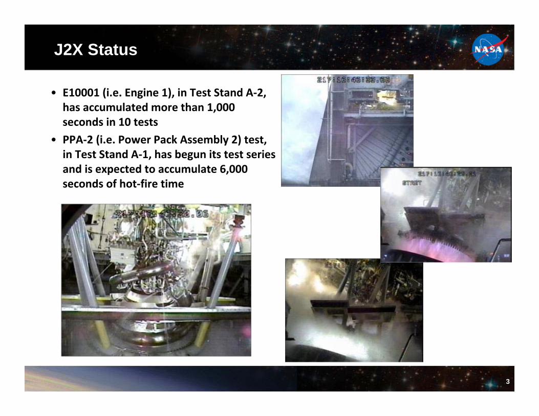
J2X Status
• E10001 (i.e. Engine 1), in Test Stand A‐2, has accumulated more than 1,000 seconds in 10 tests
• PPA‐2 (i.e. Power Pack Assembly 2) test, in Test Stand A‐1, has begun its test series and is expected to accumulate 6,000 seconds of hot‐fire time

4
MSFC’s Expander Cycle Testbed (ExCyT) Project
• During early architecture studies for the Altair lunar lander, it was determined for performance concerns, the decent engine would be a pump fed, LOX/LH2 expander cycle.
• MSFC Engineering used a small thrust class to size major components that would eventually support a full-up engine design.
• Began in 2006 under NASA IRAD funding to support design and development of the major components
• Fuel turbopump, injector, chamber, turbine bypass control valve and LOX pressure-fed control valve
• Testbed was designed to be a robust test article, flexible to addition and subtraction of key hardware, and maximize the capability of data acquisition.
• With the cancellation of the Altair program, the testbed serves the purpose to support new efforts in technology demonstration

5
P = 50.0T = 39.0
FTNK
P = 35.1T = 39.2
FPIN
P = 1415.8T = 70.2
FPDC
P = 1241.5T = 529.2
VNTIP = 1223.6T = 529.3
FDIV
P = 1206.3T = 524.3
FTI
P = 783.2T = 493.1
FTDP = 766.9T = 493.1
FIIV
W = 2.80Qdot = 4952
REGNW = 1.50Pos = 100.0%
BVNT
W = 1.31VNT
W = 2.15FTIL
W = 0.65Pos = 19.0%
FTB2
W = 2.82Pos = 100.0%
MFV
W = 2.82∆P/Pc = 9.6%
FINJ
W = 3.30Pos = 100.0%
FFCL
P = 1250.0T = 170.0
OTNK
P = 1235.5T = 170.1
OCVI
P = 1003.8T = 171.0
OCVD
P = 991.0T = 171.0
OIV1
P = 969.2T = 171.1
OIV2
W = 6.90Pos = 100.0%
OIL1
W = 10.05Pos = 100.0%
OIL2
W = 10.05∆P/Pc = 38.5%
STG2
W = 16.93CdA = 0.086
OCV2
W = 6.90∆P/Pc = 41.6%
OINJ
W = 16.95Pos = 100.0%
OFCL
Power Level = 100.0%Pc = 700.0
Set Point
MR = 6.00
η = 74.0%N = 93415
FTRBφn = 1.26
∆P = 1380.6
FPMP
ψn = 0.86τn = 1.11
ExCyTComponents System Vision Engine

6
ExCyT Technology EffortsExCyT Fuel Turbopump
•Powder Metallurgy manufacturing of complex geometry hardware and environmental material compatibility (Cost)• Partial admission turbine design and environmental characterization (Performance)• White light scanning for digital caliper clearance data of as-assembled hardware and verification of rotor assembly concentricity and straightness (Reliability and Cost)•Demonstrating the use of solid mold casting process for complex turbopump housing manufacturing (Cost and Performance)
Two Stage Injector•High performing with lower LOX pump discharge pressure requirement than High-dP•Performance and Operability via throttling
GrCop84 Advanced High Heat Transfer Chamber• Largest GRCop84 liner material in combustion chamber application for an engine system•GRCop-84 Liner has a better combination of conductivity and strength than other copper liners •Cost and Performance
Fuel Turbine Bypass Valve (FTBV)•Low actuation force across the throttle range•The piezoelectric actuator requires power only when it is commanded to change position. •Cost and Performance
Throttling Cavitating Venturi Valve (TCaV)•Simple and Reliable Design •Cost and Performance
Sensitive But Unclassified

7
Rapid Manufacturing Activities at MSFC
• J‐2X Gas Generator discharge duct– Built, hot‐fire tested, inspected, dissected– DMLS Final Report, will be submitted to the
SLS Liquid Engine Office for release Summer
• RS‐25 internally tied flex joint (ER33)– Built, structured light scanned
• F‐1 LOX inducer bolt torque adapter– Made at MSFC from Electron Beam Melting
process, Ti‐6Al‐4V alloy– Withstood 3200 ft‐lbs of torque to break free
the LOX inducer bolt
• J‐2X Fuel Turbine Exhaust Duct Maintenance Port Plug– Building DMLS parts to replace machined
parts
Excel 2007.lnk

8
F-1 Teardown Status
• F‐1 engine teardown activity is to:– Capture knowledge about the F‐1– Understand the mechanical layout of the engine and the hardware designs, – Test components to understand the F‐1 engine performance and sensitivities,– Apply knowledge to the design of a new, large LOX/RP engine.
• F‐1 teardown started on September 19, 2011, completed on November 7, 2011– 7 weeks, Team removed on the order of 840 parts (excluding fasteners).– Turbopump disassembly is currently in work.
• Hardware was removed inventoried and photographed, structured light scanned• An initial assessment was made of the condition of each component
– Cleaning method and NDE defined – Detailed assessment will be made after cleaning and NDE

9
Obsolescence Mitigation Using Available TechnologiesStructured Light Scanning System is used to document the engine assembly and components.
Electron Beam Melting (EBM) is used to generate unique tooling for the turbopump disassembly.
Scan data used for GSE design
MSFC Engine Room
10
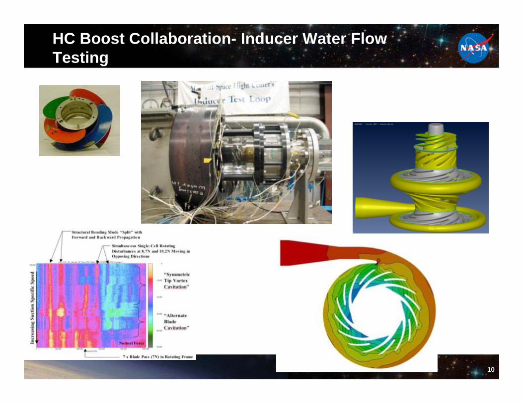
HC Boost Collaboration- Inducer Water Flow Testing

11
3GRB Collaboration - Aero-spike Nozzle Testing

12
Cryogenic Propellant Storage and Transfer Project
•Multiple NASA Centers Involved with GRC Lead • Objectives – Store cryogenic propellants in a manner that maximizes their availability for use regardless of mission duration
– Efficiently transfer conditioned cryogenic propellant to an engine or tank situated in a microgravity environment
– Accurately monitor and gauge cryogenic propellants situated in a microgravity environment
• Capabilities to be Demonstrated – LH2 Cryogenic Fluid Storage– LH2 Cryogenic Fluid Acquisition– LH2 Cryogenic Fluid Quantity Gauging– LH2 Cryogenic Fluid Transfer

13
CPST Ground Test Article (GTA) Overview
• GTA Scope:– Demonstrate thermal vacuum performance for a simulated mission environment – Perform Integrated System Performance for all modes of operation to correlate
math models and anchor Flight Payload design– Mature and evaluate flight-like design interface details for manufacturability
• Demonstrate flight tank prototype manufacturing and streamlined engineering• Demonstrate flight-like LAD manufacture and integration
• GTA Description– A technology development version of the
CPST CFM Payload with all CPST functionality
– GTA consists of flight-like:• Storage and Transfer Tanks• LADs• Transfer and Pressurization Systems• Instrumentation
– Designed to perform integrated passive and active thermal storage and transfer performance testing with LN2 and LH2 in vacuum environment

14
Chemical In-Space Propulsion
• In‐house Advance Chemical In‐Space Propulsion IRAD Funded– Need for low toxicity or green propellants – Tri‐gas thrusters for advanced satellite propulsion – Tri‐gas is a dilute stoichiometric mixture of oxygen and hydrogen gases in an inert gas such as helium or nitrogen, where the inert gas makes up 90 to 95% of the total gas volume.
– Mixture is non‐flammable and inert until flowed through an appropriate catalyst under the correct P&T
– Initial thruster design tested during 2010 summer Propulsion Academy with varying blends of 02‐H2‐N2 tri‐gas , varied % to determine effect on performance
– IRAD work will explore performance optimization and development of a flight‐like tri‐gas thruster in the one‐ to five‐pound (4.45 –22.2 N) thrust class
– Develop low cost test approach to test other green propellants
Tri‐gas Thruster
CDA Hot Fire Test Facility

15
RSRMV Testing Overview
• Testing completed under Ares Project – Development Motor (DM) Testing Full
• DM‐1 (2009): ambient motor– First full‐scale, full‐duration motor test; 650 total instrumentation channels; validated the design
• DM‐2 (2010): cold motor (400F)– Characterized new insulation material in the aft dome and different ply angle within the nozzle;
included intentional “flaws” to test redundant capture and sealing features.• DM‐3 (2011): hot motor (930F)
– Reduced insulation weight by approximately 1300 lbs; incorporated a nozzle w/different materials and contours.
– Avionics Testing• Completed component hard environment testing, single string, and multi‐string systems testing
of new avionics utilizing flight‐like engineering development units (EDUs)• Integrated the Revision 1 EDUs into the MSFC controlled demonstration test, managing the
TVC actuators and testing the control commands of the avionics boxes during a simulated flight.
• Testing completed under SLS Booster– Completed 24” Motor Test March 14, 2012
• Evaluate nozzle design changes, nozzle material changes, and insulation material changes
– Avionics Testing• Completed Flight Control Test 1 (FCT‐1) which demonstrated the new avionics subsystem's
interfacing and control of the heritage shuttle TVC system.
– Upcoming Testing• FCT‐2: September 2012• Qualification Motor #1 (QM‐1): Spring 2013• QM‐2: Fall 2014
Block 1 SLS Configuration
Block 1 Booster Design Overview• Unique thrust‐time profile• Heritage forward structures• Expendable design• New avionics• Heritage Metal Cases• Asbestos‐free insulation• Heritage TVC

16
Solid Rocket Motor Analysis Team
Launch Abort System Jettison Motor 2D char and erosion analysis including char depth after heat soak Peregrine Sounding Rocket nozzle and Insulation thermal and ablation analysis
RSRMV Joint Pressurization Routine for case and nozzle joints
RSRMV - Thermal characterization of materials
RSRMV – Carbon Cloth Phenolic nozzle char and erosion analysis
RSRMV insulation ablative material affected depth analysis
RSRMV –Carbon Cloth Phenolic Forward Nose Ring wash anomaly (erosion and char, in depth and surface heat rates and temps)
RSRM DM-6
DM-3
DM-2
DM-1

17
Solids In-house Projects
• Peregrine – New Sustainer Motor for Sounding Rocket– In‐house design for low cost, maximum reliability, and
maximize agency spin‐offs– NASA Sounding Rocket Program at Wallops Flight Facility Stakeholder
– Supports Science Missions– Teaming with AMRDEC
• Nano launcher for Cubesat IR&D Funded In‐house Project– Reduce cost of LEO access by an order of magnitude– Ultimately provide on demand launch capability for the nano‐satellite(1‐10 kg) class of payloads
– Demonstrate rapid manufacturing of solid rocket motors/stages (“Print a rocket”) using DMLS or EB
– Current Focus is on upper stage trade study, single step case liner and insulation demonstration, and defining payload, power, and communications interfaces

18
Propulsion Research and Technology Development• Non-Nuclear System Testing Approach for Nuclear Systems
– Most nuclear system technologies are thermal hydraulic in nature and can be assessed with affordable non-nuclear testing techniques. Applies to fission surface/space power (FSP) & nuclear thermal propulsion (NTP) systems.
– Nuclear Thermal Rocket Element Environment Simulator (NTREES) Facility • High pressure/high power/hot hydrogen conditions at 50kW RF heating (upgrade underway to
1.2MW)• Test envelope to evaluate small to large material samples
– Under Nuclear Cryogenic Propulsion Stage project work started on fabrication of subscale HIP ZrO2 fuel element sample for NTREES testing
• Electric Propulsion Activities & Low Thrust Test Stand– Pulsed Inductive Thruster: Ongoing R&D focused on development of conical PIT
technology• Storable Low power microwave ionization, 3 to 5kW bench test design
with power system suitable for pulse rates of 30hz.• Storable propellant operations (ammonia, middle hydrocarbon, water, etc.).
•Low thrust Variable Amplitude Hanging Pendulum with Extended Range (VAHPER) thrust stand – unique vacuum compatible test apparatus for realistic thruster evaluations.• Range of 100 micro-N to 1 N (resolution of 50 micro-N) with Impulse discrimination of 1mN-s.• Can be operated in continuous and pulsed mode; support thruster masses up to 70kg. • Specialized microwave & RF power systems, high voltage/current systems, controls and diagnostics
19
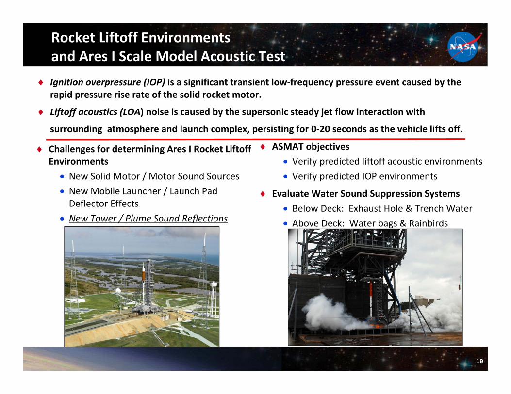
Rocket Liftoff Environmentsand Ares I Scale Model Acoustic Test
Ignition overpressure (IOP) is a significant transient low‐frequency pressure event caused by the rapid pressure rise rate of the solid rocket motor.
Liftoff acoustics (LOA) noise is caused by the supersonic steady jet flow interaction with
surrounding atmosphere and launch complex, persisting for 0‐20 seconds as the vehicle lifts off.
Challenges for determining Ares I Rocket Liftoff Environments
New Solid Motor / Motor Sound Sources New Mobile Launcher / Launch Pad Deflector Effects
New Tower / Plume Sound Reflections
ASMAT objectives Verify predicted liftoff acoustic environments Verify predicted IOP environments
Evaluate Water Sound Suppression Systems Below Deck: Exhaust Hole & Trench Water Above Deck: Water bags & Rainbirds

20
ASMAT as Pathfinder
Spatial Correlation Measurements Computational Fluid Dynamics
Materials Experiments Imaging: WALLE & Infrared

21