the - philbrick archive. 12. a method of sta- fig. 13. another effective bilizing suggested by the...
TRANSCRIPT
The
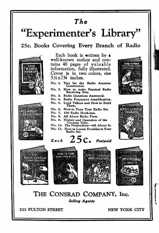
"Experimenter's Library" 25c. Books Covering Every Branch of Radio
Each book is written by a well-known author and contains 48 pages of valuable information, fully illustrated. Cover is in two colors, size 5/4 x7K inches.
ALL ABOUT • RADIO PARTS
I © T « t ( . . ^
No. 1.
No. 2.
No. 3. No. 4. No. 5.
No. 6. No. 7. No. 8. No. 9. No. 10. No. 12.
Tips for the Radio Amateur Constructor.
How to make Practical Radio Receiving Set*.
Radio Questions Answered. Radio Frequency Amplification Loud Talkers and How to Build
Them. How to Tune Your Radio Set. 100 Radio Hook-ups. All About Radio Parts. History and Operation of the
Vacuum Tube. The Neutrodyne—All About It. How to Locate Troubles in Your Radio Set.
Each 25c. Postpaid
HOW TO TU«F. you ft f- flO.O SET
(••HM.TICAI. KflOlO
ftWf(U(Ni". r,fr.v
H i
IftAOlC QUESTION
THE CONSRAD COMPANY, inc. Selling Agents
233 F U L T O N S T R E E T N E W Y O R K C I T Y


THE EXPERIMENTER'S LIBRARY, No. 13
Reflex Radio eivers
By P. E . E D E L M A N
TRADE
Published by THE E. I. COMPANY
233 Fulton Street New York City

Printed in the United State* of America
Copyright by THE E. I. COMPANY
1924
All rights reserved, including: that of translation into foreign languages, including the Scandinavian
I N T R O D U C T I O N .
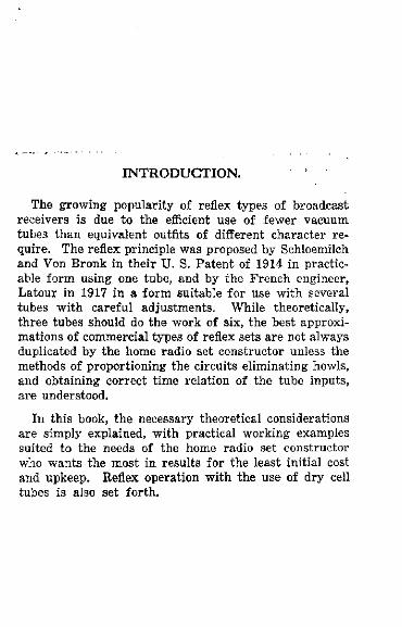
The growing popularity of reflex types of broadcast receivers is due to the efficient use of fewer vacuum tubes than equivalent outfits of different character require. The reflex principle was proposed by Schloemilch and Von Bronk in their U . S. Patent of 1914 in practicable form using one tube, and by the French engineer, Latour in 1917 in a form suitable for use with several tubes with careful adjustments. While theoretically, three tubes should do the work of six, the best approximations of commercial types of reflex sets are not always duplicated by the home radio set constructor unless the methods of proportioning the circuits eliminating howls, and obtaining correct time relation of the tube inputs, are understood.
In this book, the necessary theoretical considerations are simply explained, with practical working examples suited to the needs of the home radio set constructor who wants the most in results for the least initial cost and upkeep. Reflex operation with the use of dry cell tubes is also set forth.
R e f l e x R a d i o R e c e i v e r s
C H A P T E R I.
F U N D A M E N T A L S O F R E F L E X SETS. T H E O R Y O F C O M B I N E D A M P L I F I C A T I O N
A N D S T A B I L I Z A T I O N .
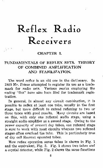
The word reflex is an old one in the dictionary. In 1923 Mr. Priess attempted to register its use as a trademark for radio sets. Various marks employing the ending "flex" have also been filed for trademark registration.
In general, in almost any circuit combination, it is possible to reflex at least one tube, usually in the first stage, but more difficult to extend reflexing to two or three tubes with good results. Many circuits are based on this, with only one reflexed audio stage, using a straight audio amplifier as a second stage. Owing to the power capacity of present day tubes, one reflexed stage is sure to work with most circuits whereas two reflexed stages often overload the tube. This is particularly true of dry cell filament operated tubes.
How reflex operation saves tubes is shown in Fig. 1 and the equivalent, Fig. 2. Fig. 1 shows two tubes and a crystal detector, while Fig. 2 shows the same functions
5

aSjaaj 1 2&*SS*El Accomplished with only one vacu-•um tube method. quency amplification
I ^
34-VIBRATIONS P E R SECOND
if)// . S O M E EARS
I O K I L O C Y C L E S \ CAN HEAR 30 • J T H E S E HIGH
VIBRATIONS.
4700 VIBRATIONS PER SEC. (HIGHEST M U S J C A L
I N S T R U M E N T VIBRATION)
I . '!C KILOCYCLES-. ( 4 0 , 0 0 0 VIBRATIONS PER. SEC.)
^ N L IMIT OF A U D I B I L I T Y fltl/^ o F 0 P - KNOWN. P E R S O N .
F R E Q U E N C I E S / /
" 6 KILOCYCLES i 5 0 , 0 0 0 METERS
(LOWEST RADIO F R E Q U E N C Y E X P E R I M E N T
A L L Y T R I E D ) I
44 RADIO, F R E Q U E N C I E S
5 \
I OVERLAP I ^ R A N G E J
INCREASING FREQUENCY (KILOCYCLES)
BROADCAST RADIO RANGE
3 0 0 M E T E R S "1000 KILOCYCLES
^ C O M M E R C I A L RADIO R A N G E
10,000 M E T E R S - 3 0 K I L O C Y C L E S U S E D BY LONG WAVE
R A D I O STATIONS
Fig. 3 . frequencies.
Showing the overlap range between radio and audio
Fig. 1 Fie. 2
REFLEX RADIO RECEIVERS
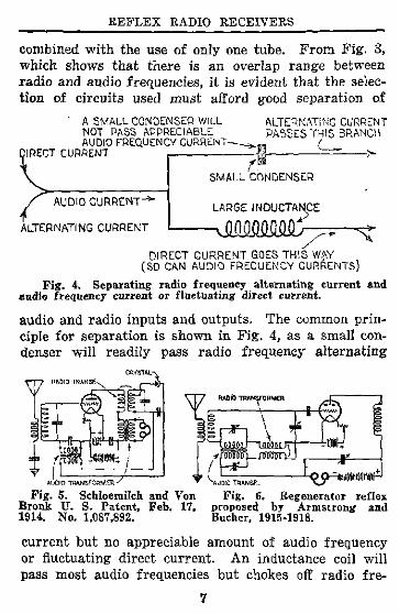
combined with the use of only one tube. From F i g . 3, which shows that there is an overlap range between radio and audio frequencies, it is evident that the selection of circuits used must afford good separation of
A SMALL CONDENSER WILL NOT PASS APPRECIABLE AUDIO FREQUENCY CURRENT
DIRECT CURRENT
ALTERNATING CURRENT PASSES THIS BRANCH
AUDIO CURRENT-
ALTERNATING CURRENT
S M A L L CONDENSER
LARGE INDUCTANCE
DIRECT C U R R E N T GOES THIS WAY (SO CAN AUDIO FREQUENCY CURRENTS)
Fig. 4. Separating radio frequency alternating current and audio frequency current or fluctuating direct current.
audio and radio inputs and outputs. The common principle for separation is shown in F i g . 4 , as a small condenser wi l l readily pass radio frequency alternating
AUDIO TRANSFORMER
Fig. 5. Schloemilch and Von Bronk U. S. Patent, Feb. 17, 1914. No. 1,087,892.
» AUDIO TRANSF-
Fig. 6. Regenerator reflex proposed by Armstrong and Bucher, 1915-1918.
current but no appreciable amount of audio frequency or fluctuating direct current. A n inductance coil wi l l pass most audio frequencies but chokes off radio fre-
7
REFLEX RADIO RECEIVERS
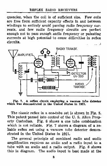
quencies, when the coil is of sufficient size. Few coils are free from sufficient capacity effects in and between windings to entirely avoid passing radio frequency currents, and few radio frequency circuits are perfect enough not to pass enough audio frequency or pulsating currents at high potential to cause difficulties in reflex circuits.
RADIO TRANSF.
Fig. 7. A reflex circuit employing a vacuum tube detector which was demonstrated in the United States in 1921.
The classic reflex in a one-tube set is shown in Fig. 5. This patent passed into control of the U . S. Alien Property Custodian. Fig. 6 shows a one tube combination which is not reliable. Fig. 7 shows a diagram of a reliable reflex set using a vacuum tube detector demonstrated in the United States in 1921.
The general principle of combined radio and audio amplification requires an audio and a radio input to a tube with an audio and a radio output. Fig. 8 shows this in diagram. The audio input is best made at the
8
REFLEX RADIO RECEIVERS
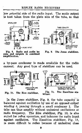
low potential side of the radio input. The audio output is best taken from the plate side of the tube, so that
AUDIO INPUT
Fig. 8. Radio and audio inputs and outputs in combined amplification.
LOOSE COUPLING DESIRABLE FOR R E F L E X
Fig. 9. The Jones stabilizer.
a by-pass condenser is made available for the radio current. Any good type of stabilizer can be used.
Fig. 10. The Rice stabilizer. Fig. 11. bilizer.
The Hazeltine sta
in the Jones stabilizer, Pig. 9, the tube capacity is balanced against oscillation by use of an opposed output winding 4, passing through a small condenser 1, The tube can thus amplify without undesired oscillations at radio frequency. The Rice stabilizer, Fig. 10, is also suited for reflex operation, and balances the radio input against oscillation. The Hazeltine stabilizer, Fig. 11, is more difficult to reflex because of undesired close
9

KEFLEX RADIO RECEIVERS
coupling of circuits. A stabilizer operating without a neutralizing condenser is shown in Fig. 12. The potential coil 3 applies a counter potential to control the tube
AUDIO OUTPUT
Fig. 12. A method of sta- Fig. 13. Another effective bilizing suggested by the author.method of stabilizing a reflex
circuit.
against undesired oscillations. Fig. 13 shows another stabilizer. A resistance of 50 to 400 ohms can also be used as a stabilizer by insertion at 4 or 5, as indicated in Fig. 14, and is sometimes incorporated in the wind-
Fig. 14 Fig. 15
ings of the coils. Fig. 15 shows how insertion of audio input and output coils at such points tends to assist stabilization. Seldom will a series resistance 6, (shown in Fig. 16) be necessary, but when a very short aerial is employed, such a resistance, adjustable up to 300 ohms,
10

R E F L E X RADIO RECEIVERS
is serviceable. A favorite method of avoiding oscillation troubles is to use an output coil 7, Fig. 17, of few turns, coupled magnetically, but only slightly capacita-tively to a tuned radio output circuit 8.
Fig. 16 Fig. 17
In using two or more tubes, several reflex methods are possible as shown in the next diagrams. Fig 18 shows the use of two tubes for radio and audio amplifica-
Fig. 18 Fig. 19
tion, proposed by Latour. Fig. 19 shows a reverse feed method for proportioning inputs and outputs. Fig. 20
Fig. 21
shows a much used essential method. Figs. 21 and 22 show other effective plans. Most of the reflex sets using
11
Fig. 20

R E F L E X RADIO R E C E I V E R S
two or more tubes operate on such plans, even when "re-invented" or exploited by different individuals.
Fig . 25
The heterodyne method of amplification brought out by Fessenden, improved by Armstrong and others, also permits use of reflex methods. Figs. 23, 24 and 25 show use of intermediate frequency or audio frequency reflex in heterodyne amplifier circuits.
12

C H A P T E R II.
O N E - T U B E R E F L E X C I R C U I T S .
Circuits employing one vacuum tube are popular because they afford good volume and can be adjusted so as not to radiate troublesome interference to neighboring receiving sets.
Fig. 26 Fig. 27
Fig. 26 shows a popular form using tuned plate circuit shunted by a crystal detector. A vario-coupler with primary 1 and secondary 2 is used. A 23 plate series condenser is used in the aerial circuit. A coil, 5, comprising 55 turns of No. 22 D.C.C. wire wound on a tube 2%, inches in diameter is tuned with a .0005 M.F . variable condenser. The crystal detector 7 may be of permanent type such as known by trade names "Pyratek," "Erla," etc. Condenser 8 is .001 M.F . Condenser 11 is .002 M.F . The audio transformer 9 is 4*/2 to 1 ratio. Condenser 10 is .001 M . F . Coil 5 should be mounted at right angles to coil 2. A potentiometer, 12, of 400 ohms is used to apply a stabilizing potential on the grid.
13

REFLEX RADIO RECEIVERS
A very simple one-tube reflex set which works without use of audio transformer is shown in F i g . 27. The coil 2 of ten turns No. 22 D.C.C. wire on tube 23^ inches
AERIAL GND PRIMARY^ IOTURNS N 2 . 2 2 D.C.C
Fig. 28. Back panel layout of a practical one-tube reflex receiving set.
diameter is loosely coupled to coil 2 of fifty-five turns, No. 22 D.C.C. wire on tube 2% inches diameter, tuned 2, of ten turns No. 22 D.C.C. wire on a tube 2 % inches
14

REFLEX RADIO RECEIVERS
tuned radio transformer may be used, with the grid terminal connected to the detector as shown. This circuit gives good volume. Fig. 28 shows a panel layout for this set.
Fig. 29 Fig. 30
Fig. 29 gives a diagram of another one-tube reflex set with two tuning controls. Coils 1 and 3 may each have twelve turns of No. 22 D.C.C. wire on a tube 2% inches in diameter. The coils 2 and 4 are similarly constructed with fifty-five turns No. 22 D.C.C. wire each, on a tube 2% inches diameter by 3 inches long. Loose coupling between the coupled coils can be had by separation of one-half inch between the coils. The coils 1 and 2 should be mounted at right angles to coils 3 and 4. Condensers 5 and 6 are each of .0005 M.F. Maximum Capacity. A five to one ratio audio transformer, 9, may be used.
A simple loop receiver, satisfactory for distance up to twenty-five miles from a broadcast station, is shown in Fig. 30. The loop may comprise twenty turns spaced one-half inch apart, wound spiral fashion, starting with inside diameter of fourteen inches.
15

REFLEX RADIO RECEIVERS
In operating reflex sets, a good crystal detector is important. If an adjustable type is used, galena or a synthetic crystal is suitable. If the crystal detector is not rectifying properly, a whistling sound may be heard which should clear on proper adjustment. As for tubes to use, one U.V.201-A is preferable, though a U.V.199 tube can be used, as well as a W.D.12. One tube can be operated satisfactorily on dry cell current supply; however, it will be a great deal more economical to use a storage battery with the U.V.201-A type.
16

C H A P T E R III.
T W O - T U B E R E F L E X CIRCUITS.
Two-tube combinations permit two stages of radio and two stages of audio amplification with a crystal detector, or one stage radio and audio with a tube detector. -
Fig. 31 shows a good combination with loose coupling between the tubes. The coils, 1, 2, and 3, 4, may have the same dimensions as those described for Fig. 29. It should be noted that a soft detector tube such as the U.V.200 requires grid return to positive terminal of the
17
Fig. 31
REFLEX RADIO RECEIVERS
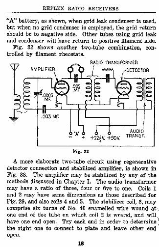
" A " battery, as shown, when grid leak condenser is used, but when no grid condenser is employed, the grid return should be to negative side. Other tubes using grid leak and condenser will have return to positive filament side.
Fig. 32 shows another two-tube combination, controlled by filament rheostats.
Fig. 32
A more elaborate two-tube circuit using regenerative detector connection and stabilized amplifier, is shown in Fig. 33. The amplifier may be stabilized by any of the methods discussed in Chapter I. The audio transformer may have a ratio of three, four or five to one. Coils 1 and 2 may have same dimensions as those described for Fig. 29, and also coils 4 and 5. The stabilizer coil, 3, may comprise six turns of No. 40 enamelled wire wound at one end of the tube on which coil 2 is wound, and will have one end open. Try each end in order to determine the right one to connect to plate and leave other end open.
18

Fig. 34
19
Fig. 33

REFLEX RADIO RECEIVERS
Some one-tube circuits can be made over into two-tube circuits by adding a vacuum tube detector in place of the usual crystal. A two element tube can be so used. The
Fig. 35
"Sodion" is another form of tube suitable as a detector for reflex circuits. A combination using "Sodion" tube is shown in Fig. 34. Special resistances, 1 and 2, of thirty ohms each, are required in this circuit. The "Sodion" tube is non-regenerative, thus, oscillating troubles are avoided by its use. In other respects, this circuit is the same as usual.
A two-tube circuit suitable for dry cell operation is shown in Fig. 35. Coils 1 and 2 may have dimensions as described for Fig. 29. A 200 ohm adjustable resistance may be used for stabilizing when a short aerial is employed. A fixed transformer is used for one radio stage, while the other radio stage is tuned. The audio transformers used should be three to one or four to one
20

Fig. 36
Fig. 37
21

REFLEX RADIO RECEIVERS
in ratio. TJ.V.199 tubes may be used, but the first tube will operate better if of U.V.201-A or C.301-A type. Separate " A " battery leads will have to be provided in case two tubes of different types are used.
Fig. 36 shows a popular two-tube circuit which is easy to operate. The first radio stage is tuned, and the second radio stage uses a fixed transformer. The second tube is reflexed by means of a permanent type of crystal detector.
In assembling two-tube circuits, care should be taken to connect the terminals according to their proper battery polarities. Label binding posts correctly so that the user will not get the " B " battery leads across the tube filaments. Test circuits as wiring proceeds.
Fig. 37 shows a two-tube combination with an extra stage of audio frequency added. Before considering further circuits, some of the apparatus requirements will next be taken up.
22

C H A P T E R IV.
P A R T S U S E D I N R E F L E X C I R C U I T S .
In reflex circuits, good parts are essential. The circuits have to stand up under service conditions where high potential audio currents as well as radio frequency currents are combined. Insulation must be good, and it is well to test each part before using it.
The parts discussed in the following are to be considered as illustrations of desirable types rather than particular makes as there are many good types of suitable construction on the market.
Variable tuning condensers, F ig . 38 are best of the vernier type or operated by a vernier control dial in
order to secure fine adjustment. A l l fixed condensers should be of the mica dielectric type, as shown in F ig . 39 or similar. Rheostats for detector tube control are preferably of the fine adjustment type as shown in Fig. 40.
Condensers.
Fig. 38 Fig. 39 Fig. 40
23
REFLEX RADIO RECEIVERS
Coils.
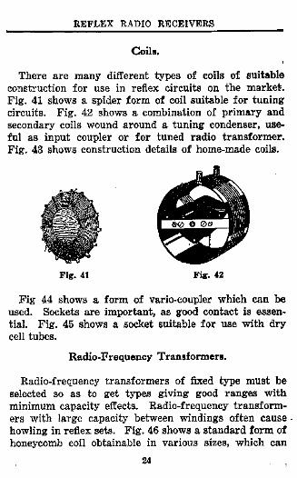
There are many different types of coils of suitable construction for use in reflex circuits on the market. Fig. 41 shows a spider form of coil suitable for tuning circuits. Fig. 42 shows a combination of primary and secondary coils wound around a tuning condenser, useful as input coupler or for tuned radio transformer. Fig. 43 shows construction details of home-made coils.
Fig. 41 Fig. 42
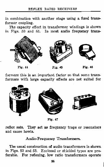
Fig 44 shows a form of vario-coupler which can be used. Sockets are important, as good contact is essential. Fig. 45 shows a socket suitable for use with dry cell tubes.
Radio-Frequency Transformers.
Radio-frequency transformers of fixed type must be selected so as to get types giving good ranges with minimum capacity effects. Radio-frequency transformers with large capacity between windings often cause howling in reflex sets. Fig. 46 shows a standard form of honeycomb coil obtainable in various sizes, which can
24

R E F L E X RADIO RECEIVERS
be used in reflex sets. This type of coil is usually employed in connection with a shunt variable condenser and for radio amplifier coupling. Fig. 47 shows suitable types of fixed radio transformers.
FIBER TUBE-
STABILIZING COIL MAY BE WOUND ON THIS END
SECONDARY 55 TURNS.,
PRIMARY- 12 TURNS
Fig. 43
Fixed radio transformers generally operate best at certain wavelength ranges. Figs. 48 and 49 show how response varies at different wavelengths. One stage of tuned radio amplification can be employed satisfactorily
REFLEX RADIO RECEIVERS
in combination with another stage using a fixed transformer coupling.
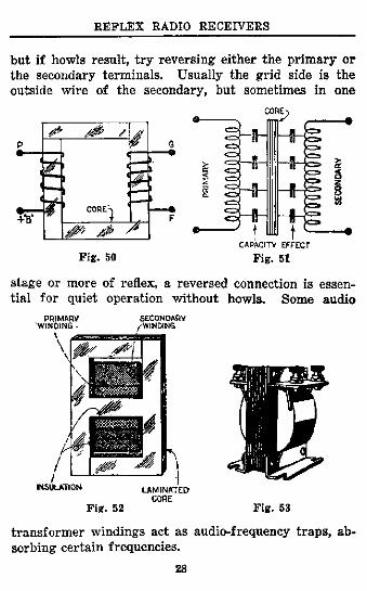
The capacity effect in transformer windings is shown in Figs. 50 and 51. In most audio frequency trans-
Fig. 44 Fig. 45 Fig. 46
formers this is an important factor so that some transformers with large capacity effects are not suited for
Fig. 47
reflex sets. They act as frequency traps or resonators and cause howls.
Audio-Frequency Transformers.
The usual construction of audio transformers is shown in Figs. 52 and 53. Enclosed or shielded types are preferable. For reflexing, low ratio transformers operate
26

REFLEX RADIO RECEIVERS
satisfactorily whereas, in higher ratios, few makes of transformers prove efficient. Three or four to one ratio can usually be used. Some makes permit five or six to
Fig. 48. Amplification curves of fixed radio-frequency transformers.
one ratio. Sometimes it is necessary to leave the filament return from the grid of the audio circuit open, so that the high ratio transformer will not cause howls.
Fig. 49. Relative sensitivity of radio-frequency transformers at various wavelengths.
In using transformers, follow labelled terminals, plate terminal to the plate of the tube, grid to the grid, etc.,
27
REFLEX RADIO RECEIVERS
but i f howls result, try reversing either the primary or the secondary terminals. Usually the grid side is the outside wire of the secondary, but sometimes in one
C A P A C I T Y E F F E C T
Fig. 50 Fig. 51
stage or more of reflex, a reversed connection is essential for quiet operation without howls. Some audio
P R I M A R Y S E C O N D A R Y " W I N D I N G • / W I N D I N G
I N S U L A T I O N L A M I N A T E D C O R E
Fig. 52 Fig. 53
transformer windings act as audio-frequency traps, absorbing certain frequencies.
28

R E F L E X RADIO RECEIVERS
Resistances.
Variable resistances—a rheostat, grid leak and poten-
Fig. 54 Fig. 55 Fig. 56
tiometer are shown in Figs. 54, 55 and 56. Non-inductive types are preferable for some circuits.
Crystal Detectors.
Many crystal detectors are tricky in adjustment and variable in sensitivity. Galena and pyrites (iron, etc.)
Fig. 59
are usually used with fine contact points. Zincite, Bornite, or other two-crystal combinations are sometimes used. A popular type of fixed crystal detector is
29
REFLEX RADIO RECEIVERS
shown in Fig. 57. Other crystal detectors of the adjustable and semi-permanent types are shown in Figs. 58 and 59.
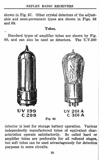
Tubes.
Standard types of amplifier tubes are shown by Fig . 60, and can also be used as detectors. The U.V.200
O V 1 9 9 U V 201 A C 2 9 9 C 3 0 1 A
Fig. 60
detector is best for storage battery operation. Various independently manufactured tubes of equivalent characteristics operate satisfactorily. So called hard or amplifier tubes are preferable for all reflexed stages, but soft tubes can be used advantageously for detection purposes in some circuits.
30
R E F L E X RADIO RECEIVERS
Wiring a Reflex Set.
In wiring, it is best to assemble the radio-frequency circuit first and test it separately as a regular radio-frequency set, leaving the audio wiring for later attention. If the radio circuit is going, the audio additions can be added stage by stage and tested for certain success. In testing several stages of radio amplification, a fixed crystal detector in series with a headset can be successively connected across the outputs of each radio stage. If results are poor or lost, and no short or open circuits are found, perhaps a stabilization connection is required to control regeneration effect through the amplifier tube. Connections of the radio-frequency current carrying circuits should be short and direct. If necessary, the audio-frequency circuits can be located further away with longer connections, but audio-frequencies at high potentials can also leak by capacity effects in parts and or by close wiring, causing audio regeneration effects and howls. Anyone who builds a reflex set and gets the best results right away without further adjustments or changes can consider such as lucky craftsmanship, as even factory built sets need to be tried and tested in the course of construction.
31
C H A P T E R V .
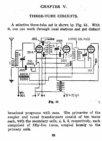
T H R E E - T U B E CIRCUITS.
A selective three-tube set is shown by Fig. 61. With it, one can work through local stations and get distant
broadcast programs with ease. The primaries of the coupler and tuned transformers consist of ten turns each, with the secondary coils, 4, 5, 6, respectively, each comprised of fifty-five turns, coupled loosely to the primary coils.
32

RADIO DETECTOR-
"A"* "b" <»
Fig . 62
OUTPUT DETECTOR
AUDIO TRANSF
Fig . 63
33

R E F L E X RADIO R E C E I V E R S
In the circuit of F ig . 62, a potentiometer is shown as a stabilizer and wil l broaden the tuning so that the directional effect of the loop wil l come in handy when local stations have to be worked through. Adjustment of each filament rheostat wil l permit quiet operation. F ig . 63 shows a well known circuit employing a direct feedback and reverse-feed audio amplifier with addition of a resistance stabilizer.
:34

C H A P T E R V I .
F O U R - T U B E C I R C U I T S .
Four-tube reflex circuits afford the most satisfactory loud-speaker results, especially if a short indoor aerial loop or phantom input is to be used. F ig . 64 shows one of these circuits. One rheostat controls the detector and the other the amplifier tubes. The first audio transformer is shown with one terminal open. Most types of transformers wil l work this way while some types will only operate effectively with usual closed connection as shown by the dotted lines.
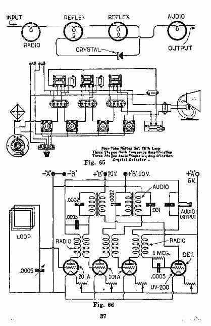
A four-tube circuit, better known as the "Acme" circuit, is shown in F ig 65. It employs potentiometer control, three audio and three radio stages, with crystal detector, and operates with good volume. Similar circuits are exploited under the name "Erla," etc. Manufacturers who thus furnish complete parts fitting together in operative circuit have done much to popularize home construction of reflex sets. The most popular circuits for which "Er la" parts are made are shown in Figs. 36 and 37.
Fig . 66 shows a four-tube set controlled by filament rheostats. F ig . 67 shows the neutrodyne reflex arrangement with the first tube reflexed. F ig . 68 shows a four-tube combination with inductance stabilized, reversed feedback, radio amplifier reflexed with two tubes used for a push-pull second audio-frequency stage. This arrangement gives good volume, but requires careful
35

CO
RADIO T R A N S F . (FIXED) OPEN FOR LOOP
GROUND FOR P H A N T O M / .000001 MF. I0.0C0 OHMS §
RADIO TRANSF. (FIXED OR TUNED)
LOOP 16T. 3 0 n S I D E ± "A V S P A C I N G . NS. 16 - + WIRE OR 3 5 T . S P I D E R W E B FOR P H A N T O M
L E A V E O P E N O N HIGH RATIO T R A N S F
Fig. 64
CAPACITY OF S E T 'AND •vkr B A T T E R I E S - T O GROUND
V
REFLEX AUDIO
. fonr Tube H«*lex StX With Loop Throe S U ; - l rl.c'i. FVtquoncy Amplification Three Stages AoiitFrcqueneii Amplification
F i g . 65 c ^ t ' t 4 , 0 < t , e t , r *

CO
Fig. 64

F i g
. Few Tufcc R a « « x Sat Wifli L»p ITirae S t R « * l » rrtqutncn Amplification Thra* Stagai AnJU Fraqacnci) Amplif icatian
„ _ Cructal Octactar .
IK. 65
F i g . 66
87

Fig. 67
CO 0 0

Fig. 68
CO CO
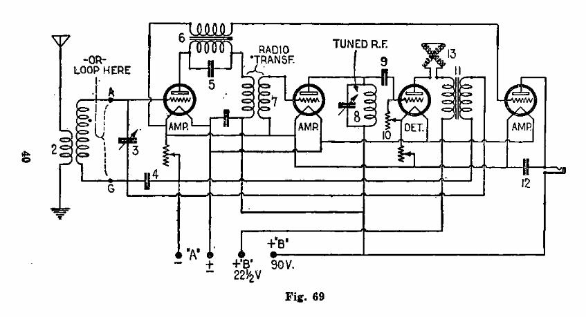
Fig. 69
o

Fig. 70
f—*

Fig. 71
to

REFLEX RADIO RECEIVERS
adjustment of coil 5 in opposition to coil 15. The coupler, 4, has four turns of No. 22 wire on the primary winding, loosely coupled to secondary, 15, comprising 42 turns No. 22 D.C.C. wire on a tube 4 inches in diameter. The coil 5 is wound with forty-six turns on a rotor, coupled to coil 15 and connected to oppose coil, 15. The rotor has an average diameter of 3 ^ inches. It is also possible to reflex push-pull amplifiers but usually little is gained, as the regular arrangement affords all the amplification required.
Fig. 69 shows another four-tube circuit capable of powerful amplification yet affording ample selectivity to work through local stations.
Fig. 70 shows use of double loop input. The tuned loop is insulated from the remainder of the circuit but can transfer energy to the coupled loop, permitting maximum operation of the audio amplifier on different inputs without howling.
Fig. 71 shows a four-tube set using U.V.199 tubes, with two tubes in parallel. This gives greater volume. Regenerative detector circuit is also successfully used but radiation is prevented by the reflexed tube. The use of two coupled variometers for input prevents capacity difficulties.
43

C H A P T E R V I I .
C O M P L E X R E F L E X C I R C U I T S .
There are various complex types of reflex circuits which are difficult to be placed in operation by a home builder. F i g . 72 shows a Heterodyne amplifier in which
Fig. 72
aii intermediate stage is reflexed through the first radio amplifier tube. F i g . 73 shows a Heterodyne-reflex circuit, or reflex applied to the Super-Heterodyne circuit.
44

CI
Fig. 73

C H A P T E R VII I .
O P E R A T I O N O F R E F L E X SETS.
The best aerial arrangement for operating a reflex set is shown in F ig . 74. A shorter aerial may require use of a resistance stabilizer. A longer one wi l l broaden
GARAGE OR N9.I4 COPPER WIRE HOUSE TOP SUPPORT POLE SUPPORT \ \
the tuning. Details for constructing a suitable loop are given in F ig . 75. F ig . 76 shows a form of factory-made loop.
\
WATER PIPE- 4
Fig. 74
46

R E F L E X RADIO R E C E I V E R S
For loud-speaker operation, there are various phonograph adapters, such as shown in F ig . 77. This device makes it possible to use the sound chamber of the phono-
Fig. 75 Fig. 76
graph. Practically any standard type of loud-speaker using a permanent magnet is suitable for reflex set operation.
Fig. 77
Figs. 78 and 79 show how a wave trap may be added to ordinary reflex sets if required to cut out strong local stations.
47

R E F L E X RADIO RECEIVERS
Batteries.
Batteries of suitable dry cell type are shown in Fig. 80. A storage battery, Fig. 81, and charger, Fig. 82,
Fig. 78 Fig. 79
will be useful when three or four-tube sets are operated with tubes requiring current supply over one-half ampere.
By-passing condensers may often be eliminated from reflex circuits as transformers have considerable capacity effect. This can be ascertained by experiment.
48

R E F L E X RADIO RECEIVERS
When reflex sets are operated on a loop and phantom input, the volume and distance results will be about equal. The phantom input method is shown in Fig. 64 and is effective over a usual range of two thousand miles. Any
reflex set employing two or three stages of radio-frequency amplification will operate over long distances with a short indoor aerial, loop, or phantom input circuit. A one-tube set will operate over long distances with a good outdoor aerial and for short distances with loudspeaker volume, even with a reasonably good indoor aerial. .
The reader will be able to choose the circuit desired, mount it properly, wire it correctly, test and get it going 0. K . without being a slave to dimensioned blue prints requiring purchase of certain makes of parts which are not always easily obtainable, or will be able to improve an old set by reflexing one or more stages.
Reflex sets are subject to induction disturbances causing audio noises coming from signal and power lines nearby. The best way to limit these when they cannot be filtered or tuned out is to have the first tube used as
Fig. 81 Fig. 82
Induction Disturbances.
49

R E F L E X RADIO RECEIVERS
the last audio stage, or to use one stage of radio ahead of the usual circuit with a choke coil by-pass for audio currents.
Other Troubles.
Assuming that set is 0. K., troubles may be caused by " A " batteries running down, " B " batteries deteriorating to a point giving fluctuating current supply, loose contacts in tube sockets, poor vacuum tubes, moist dust accumulating on plates of variable condensers, or loose joints in wiring. This is true for any type of sensitive receiving apparatus as well as reflex sets.
Simple Wiring Desirable.
The use of numerous switches and jacks in reflex circuits affords more opportunity for feedback of circuits to cause howls, so should be avoided. Many forms of automatic switch jacks which work well in other circuits, are not suitable for reflex outfits.
Howls.
Howls are audio-frequency regenerated or heterodyned results not wanted in reflex operation. Use of condensers to stop howls consists in experimentally proportioning different values of fixed condensers as shunts windings of a transformer will need to be increased or across the audio-frequency coils. Sometimes a fixed condenser connected across the primary and secondary decreased to stop howling. The principle is to use as small a condenser as possible without securing howls; as a better potential builds up across a small condenser.
50
R E F L E X RADIO R E C E I V E R S
Howls can also be stopped by turning down one or more filament rheostats, by using a potentiometer to adjust grid input potential, by reversing one or more leads of the transformers used, by separating the circuits further apart, or by adjusting the radio input to prevent overloading of the radio stages of amplification. When faults such as leaky condensers are found, and everything else seems 0. K. , audio howl may still be caused by the vibration of the loud-speaker to the vacuum tubes via the air, and can be remedied by mounting the set on pads or moving the loud-speaker further away from the receiving set. The last audio stage wiring is at high audio-frequency potential and must be kept away from other wires as much as possible to prevent capacity and coupling leakage which will cause regenerative audio howls. In using a loop with a tuned radio-frequency set, i t is necessary to shield the set against the loop to prevent intercoupling effects between the loop and the tuned radio transformer coils. Usually a grounded tin foil shield suffices for this. The use of loose coupled radio transformers further avoids audio feedback difficulties. Properly built, reflex radio sets afford very powerful amplification, which, tube for tube, surpasses that of most any other circuit possible to assemble.
51

" T H E R A D I O C O N S T R U C T O R "
This receiver is the last word in improved Super-Heterodynes. It employs six tubes and is, without doubt, the most sensitive circuit in existence at the present time. It engages what has been called the "Modulation System" of rectification in place of the usual "Frequency Change" of the received radio currents as in the standard Super-Heterodyne.
The description of this Pattern is written by R. E . Lacault, who devised the Ultradyne; thus, the constructor can feel assured that he is following authentic data.
Complete instructions given in a four-page pamphlet, one large blue print Pattern showing Perspective Wiring Diagram, Coil Winding Forms, Full Size Panel Layout and details for building a cabinet. Contained in a heavy two-color printed envelope, size 9x12 inches.
Pattern No. 10
H O W T O M A K E
The Ultradyne By R. E. LECAULT, Associate Editor of Radio News
T H E CONSRAD C O M P A N Y , inc.
233 FULTON STREET NEW YORK CITY

BUILD YOUR C O C K A D A Y SET FROM A CONSRAD PATTERN How To Make
A Cockaday Receiver Pattern No. 6
The Cockaday four-circuit tuner is one of the latest advancements in radio. Its main advantage lies in the fact that the set can be adjusted to the highest point of regeneration, and tuning accomplished over a wide band of wave-lengths without the necessity for readjustment the regeneration control. The set described in our packet was designed and built at our own shop. A l l dimensions, size of
wire, number of turns, etc., are given, leaving nothing to the imagination.
The Packet consists of a fully illustrated instruction Pamphlet, size 8 % x l l ^ inches and two large Blue Print Patterns—one of the Actual Size Panel Layout with directions for building a suitable cabinet, and one Perspective Wiring Diagram of the Set.
Contained in a Two-Color Printed Envelope, size 9x12 inches.
Price 50c. Prepaid
How To Make A Five Tube Cockaday Receiver
With Push-Pull Amplification Pattern No. 11
This pattern gives the complete assembly, wiring, adjusting and tuning details for the new Cockaday five-tube receiver with Push-Pull amplification. The set as described in our pamphlet of instructions is one of the best receivers for the reception of distant stations due to its remarkable selectivity. It is also noted for great volume, as the power amplifier of the Push-Pull type used in this set is, without question, a big improvement over other forms of audio frequency amplifiers.
Complete instructions in a four-page pamphlet. Size 8^x11 inches. One large blue print Pattern showing a Perspective Wiring Diagram, and Full Size Panel Layout. Contained in a heavy two-colored printed envelope, size 9x12 inches.
Price 50c. Prepaid
THE CONSRAD CO., Inc. 233 Fulton Street N . Y . C.

" T H E R A D I O C O N S T R U C T O R " Pattern No. 13
HOW TO MAKE
The Harkness Receiver
The Harkness Receiver is essentially a Reflex circuit which successfully employs tuned radio frequency amplification without the necessity of using a potentiometer or neutralizing condensers to prevent self-oscillation. Those who are familiar with radio circuits and their operation will readily realize the importance of this achievement in radio frequency amplification and will be astonished with the remarkable sensitiveness and selectivity of this set.
Since the Harkness Receiver does not oscillate, it follows that the operation is simple. The set has only two dial controls, and when the best positions of these have been found for various stations, the positions can be permanently logged for future reference. In this way it is not necessary to search for a particular station. Any desired station can be received by turning the two dials to the positions which have been recorded beforehand on the log. The set will also operate efficiently on a loud-speaker and the use of a crystal detector gives clear and undistorted reproduction of speech and music.
In addition to the several combined features of this set, it is simple and inexpensive to build. A comparatively small number of. parts are used and they can be easily assembled according to the directions given in a four-page instruction pamphlet and. two blue-print pattern sheets. Contained in a heavy two-color printed envelope, size 9x12 inches.
Price 5 0 C . Prepaid
T H E CONSRAD COMPANY, inc. 233 F U L T O N STREET N E W . Y O R K CITY
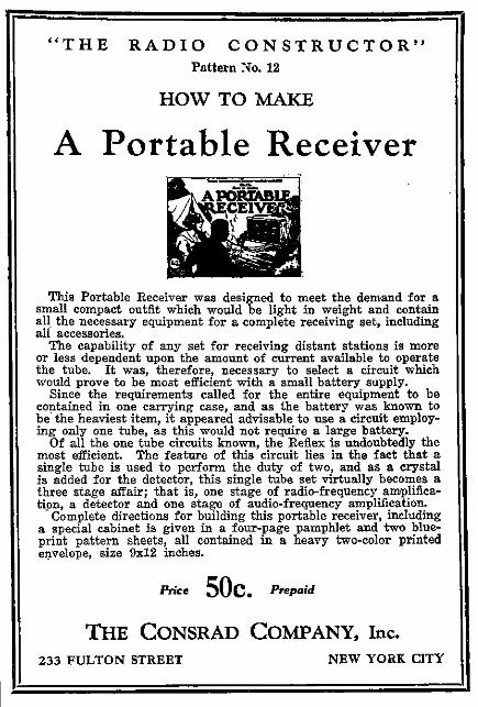
" T H E R A D I O C O N S T R U C T O R " Pattern No. 12
HOW TO MAKE
A Portable Receiver
This Portable Receiver was designed to meet the demand for a small compact outfit which would be light in weight and contain all the necessary equipment for a complete receiving set, including all accessories.
The capability of any set for receiving distant stations is more or less dependent upon the amount of current available to operate the tube. It was, therefore, necessary to select a circuit which would prove to be most efficient with a small battery supply.
Since the requirements called for the entire equipment to be contained in one carrying case, and as the battery was known to be the heaviest item, it appeared advisable to use a circuit employing only one tube, as this would not require a large battery.
Of all the one tube circuits known, the Reflex is undoubtedly the most efficient. The feature of this circuit lies in the fact that a single tube is used to perform the duty of two, and as a crystal is added for the detector, this single tube set virtually becomes a three stage affair; that is, one stage of radio-frequency amplification, a detector and one stage of audio-frequency amplification.
"Complete directions for building this portable receiver, including a special cabinet is given in a four-page pamphlet and two blueprint pattern sheets, all contained in a heavy two-color printed envelope, size 9x12 inches.
Price O U C . Prepaid
T H E CONSRAD COMPANY, inc. 233 F U L T O N STREET NEW Y O R K CITY

" T H E R A D I O C O N S T R U C T O R " Pattern No. 5
H O W T O M A K E
A Reflex Receiver
The plans for this Reflex Receiver were issued after considerable research work by our engineers. Most people have trouble with reflex receivers. It takes an expert to build one that will work satisfactorily. The constructional details of a reflex receiver, contained in this packet, are the results of successful efforts.
This Packet contains a Four-Page Illustrated Pamphlet, size 8V2 x liy2 inches and Two Large Blue Print Patterns—one of the Actual Size Panel Layout with Directions and Sketches for building a suitable Cabinet, and one Perspective Wiring Diagram of the Set.
A l l contained in a Two-Color Printed Envelope, size 9 x 12 inches.
Price 5 0 C . Prepaid
T H E CONSRAD C O M P A N Y , inc. 233 FULTON STREET NBW YORK CITY

" T H E R A D I O C O N S T R U C T O R " Pattern No. 4
H O W T O M A K E
A Reinartz Receiver
The original Reinartz Receiver is the most popular type of set in existence today. It gained its popularity through its simplicity of long-distance reception. Full directions for building this receiver are given in this packet. The connections of the set are shown plainly, so that the novice will have no trouble in following them.
The Packet contains a Four-Page Illustrated Pamphlet, size Sy2 x liy2 inches and Two large Blue Print Patterns—one of the Actual Size Panel Layout with Directions for making a suitable cabinet, and one of a Perspective Wiring Diagram of the Set.
A l l contained in a heavy Two-Color Printed Envelope, size 9 x 12 inches. ,
Price 5 0 C , Prepaid
T H E CONSRAD C O M P A N Y , inc. 233 FULTON STREET NEW YORK CITY

Radio Broadcast Listener's Book of Information and Log Record
To the countless thousands of enthusiastic broadcast listeners thirsting for Information but lacking: in technical knowledge, this book is specially dedicated. It describes in every-day understandable language how to select the set for your particular requirement, how to erect the aerial and install your set, how to operate it and the proper method of upkeep and maintenance of batteries etc.
The four main divisions of this book are as follows:
Part A—Information for the Broadcast Listener. Part B—Radio Broadcast Station of the U. S. by call letters. Part C—Radio Broadcast Station of the U. S. by States. Part D—Log of Broadcast Stations and Station Log Chart.
In part B you will find a complete list of Radio Broadcast Stations with name, location, power, wave-length and sending hours of the Station Indexed alphabetically according to their call letters. There are several pages of Log sheets for the keeping of records of the broadcast stations heard and also special tuning charts for making curves of the wavelength and dial settings for a set. Contains 2 pages, size 5%x9*4 inches, loose-leaf.
Price 50c. Prepaid
"RADIO NEWS" AMATEUR'S HANDIBOOK
Volume No. 1 Chock full of radio constructive and In
structive articles from cover to cover. Written by foremost radio authorities, in plain everyday language which everyone can understand. Sections include articles on Receiving Sets and Sundry Apparatus, Transmitters and Accessories, Radio Theory, Vacuum Tube Data, and Practical Hints for the Amateur. A book which also serves as a ready reference and should find a place In the library of every amateur, it contains 244 pages and over 375 illustrations, diagrams and photographs bound in a multi-colored heavy board.
On sale at all leading radio stores. If your dealer cannot supply you, send a dollar bill and the book will be forwarded to you postpaid.
Price $1.00 Prepaid
T H E CONSRAD COMPANY, inc. 233 FULTON STREET NEW YORK CITY

"The Electrical Magazine for Everybody"
# 3
100 Articles and Over 100 Illustrations
PR A C T I C A L E L E C T R I C is p robab ly the most novel magazine of i t s k i n d ever conceived. It is personal ly edited by
H . Gernsbach. editor of S C I E N C E & I N V E N T I O N , M O T O R C A M P E R & T O U R I S T and R A D I O N E W S . M r . Gernsbach, who founded the old " M o d e r n E l e c t r i c s " as we l l
as the " E l e c t r i c Expe r imen te r , " knows thoroughly wha t his readers w a n t and have wanted for many years. P R A C T I C A L E L E C T R I C S , the 100% electr ical magazine, eclipses the best tha t was i n " M o d e r n E l e c t r i c s " and " E l e c t r i c a l Expe r imen te r . "
For Sale at All Newsstands. 25c. the Copy. $2.50 a Year. Canada and Foreign—$3.00 a Year
Motoring Winter, Summer, Autumn and Spring MOTOR
CAMPER & TOURIST
A magazine dedicated to the vas t a r m y of campers and touris ts who w a n t to k n o w how and where to go. The in teres t ing and ins t ruc t ive art icles, photos and sketches each month w i l l help y o u to decide correc t ly these most impor tan t points.
It covers ar t ic les on a lmost every outdoor sport tha t can be indulged i n whi le Motor Camping, such as when Mother , D a d , Sis ter and B r o t h e r and the k ids s w i m , hunt fish golf, h ike , snap photos, p lay tennis, c l i m b mountains, l i s ten i n on their camp R a d i o . and otherwise indulge i n the i r innumerable
pet hobbies.
SUBSCRIPTIONS $2.50 THE YEAR—FOREIGN 50c EXTRA ON ALL NEWSSTANDS 25c THE COPY
GERMOTT PUBLISHING CO., Inc. 53 Park Place New York City

R a d i o ' s G r e a t e s t M a g a z i n e
ON ALL NEWSTANDS 25c« the copy
Subscriptions $2.50 the year Foreign 50c. extra
l St - in every Department
1st—In Circulation The distribution of the November Issue of RADIO NEWS was 400,000 copies. A gigantic number of books. This more than doublet the output of any other Radio Publication.
1st—In Advertising RADIO N E W S carries more than twice as much advertising as any other Radio Magazine. The number of lines of advertising in the November issue is 63,098. When you want to buy equipment read the advertising pages of RADIO N E W S .
1st—In News There is no vital development in radio that is not sooner or later in the pages of RADIO NEWS. RADIO N E W S is first in presenting the modern developments in Radio. RADIO N E W S was first in presenting the revolutionary development of the SOLO DYNE, the tube that needs no "B" batteries. First in the introduction of.the CRYSTODYNE. the oscillating crystal detector.
Radio for the Non-Technical Reader The Great Magazine of Scientific
and Inventive Happenings Not only does Science and Invention cover every single new development in the great world of Science but it also carries in its pages every month a special nontechnical radio section for those radio fans who are interested in radio from the standpoint of the well informed amateur. This is in line with the policy of Science and Invention to make everything, even the most intricate scientific developments, understandable to everyone.
ON ALL NEWSSTANDS 25c the copy Subscriptions $2.50 the year
Foreign 50c. extra
5Cltnce and Invention
K t l K T U T MAX M COLO
Orer 40 Non-Technical Radio Articles Every HonfL
EXPERIMENTER PUBLISHING COMPANY, Inc., 53 Park Place, N. Y. City