the optoelectronic systems for vertical deformations … · the optoelectronic systems for vertical...
TRANSCRIPT

TS3 Standards, Quality Assurance and Calibration Ľubomír Ondriš, Štefan Lukáč, Viktor Rusina, Ján Buzási and Dušan Krušinský TS3.6 The Optoelectronic Systems for Vertical Deformations and Tilt Measurement of Objects and Technological Equipment FIG Working Week 2004 Athens, Greece, May 22-27, 2004
1/13
The Optoelectronic Systems for Vertical Deformations and Tilt Measurement of Objects and Technological Equipment
Ľubomír ONDRIŠ, Štefan LUKÁČ, Viktor RUSINA, Ján BUZÁSI, Dušan
KRUŠINSKÝ, Slovak Republic
Key words: automated survey system, hydrostatic levelling, pendametry, optoelectronic measuring system, CCD sensor. SUMMARY The hydrolevelling and pendametric measuring systems developed in Institute of Measurement Science Slovak Academy of Sciences in cooperation with Department of Surveying Slovak Technical University are described. They are assigned to vertical deformations and tilt measurement of objects and technological equipment. The high measuring accuracy and high long-term stability of metrological parameters is achieved by means of optoelectronic method. The specific applications of developed systems in several application fields are also brought. ANOTÁCIA Opisujú sa hydronivelačné a pendametrické meracie systémy, vyvinuté v Ústavu merania Slovenskej akadémie vied v spolupráci s Katedrou geodézie Stavebnej fakulty Slovenskej technickej univerzity na meranie polohy rozľahlých objektov v priestore. V oboch meracích systémoch sa aplikáciou optoelektronických metód a prvkov dosahuje vysoká presnosť merania a dlhodobá stabilita metrologických parametrov. V závere sa uvádzajú konkrétne aplikácie vyvinutých systémov na Slovensku i v zahraničí.

TS3 Standards, Quality Assurance and Calibration Ľubomír Ondriš, Štefan Lukáč, Viktor Rusina, Ján Buzási and Dušan Krušinský TS3.6 The Optoelectronic Systems for Vertical Deformations and Tilt Measurement of Objects and Technological Equipment FIG Working Week 2004 Athens, Greece, May 22-27, 2004
2/13
The Optoelectronic Systems for Vertical Deformations and Tilt Measurement of Objects and Technological Equipment
Ľubomír ONDRIŠ, Štefan LUKÁČ, Viktor RUSINA, Ján BUZÁSI and Dušan
KRUŠINSKÝ, Slovak Republic
1. INTRODUCTION Determination of the large construction and engineering objects vertical deformations and tilt during the building, manufacturing, or assembly period is a frequent requirement in technical practice. Anyway the monitoring of these parameters is required also in period of their exploitation. Preservation of the functional ability of mentioned objects, is the decisive reason for the long-term, or sometime also continual monitoring of these objects. As an example, we can mention the particle accelerators monitoring in the high-energy physics basic research. In another cases, the maintaining of the operational safety and also environment conservation is very important. We can mention the case of the nuclear, or water power plants. 2. MEASURING METHODS 2.1 Method of the Hydrolevelling Precise measurement of the important object functional parts vertical deformations, or elevations are performed by the classical geodetic methods. Due to development of optoelectronic measuring methods, a renaissance of the well-known hydrolevelling method can be observed. Using right this optoelectonic method, there is possible precise continual measurement of relative height of liquid levels in hydrolevelling sensors, what is the basis of the hydrolevelling. If a certain physical condition (Vasjutinskij 1983) are fulfilled, common horizontal plane of levels in all sensors can be used as the reference plane for the sensors elevations determination. 2.2 Pendametric Method The pendametric method is suitable for precise biaxial measurement of the objects angle deviation from the plumb line and its time dependent changes. This method is based on the position measurement of vertical damp pendulum wire in a reference horizontal plane. (Practically identical optoelectronic method. is possible to use for this purpose.) Pendulum is in its hanging point connected with the measured object, as is shown in Fig. 1.

TS3 Standards, Quality Assurance and Calibration Ľubomír Ondriš, Štefan Lukáč, Viktor Rusina, Ján Buzási and Dušan Krušinský TS3.6 The Optoelectronic Systems for Vertical Deformations and Tilt Measurement of Objects and Technological Equipment FIG Working Week 2004 Athens, Greece, May 22-27, 2004
3/13
Fig. 1: The principle of pendametric method 2.3 The Influence of the Limiting Factors The identical density of used liquid and equal atmospheric pressure above liquid levels of the connected vessels system are conditions for hydrostatic equilibrium in the hydrolevelling method. The condition of equal atmospheric pressure above liquid levels can be easy viable by means of sensor spaces above levels interconnection in whole system, and connecting this space with free atmosphere in one place. The limiting factor of this method is thus the temperature dependence of used liquid density. This problem is particularly soluble by means of temperature measurement in all sensors of system and then subsequent result correction. Exact correction requires perception of temperature spread over the whole system, including the interconnecting pipes. Pendametric method measurement is not so sensitive to temperature changes. However on the wire and weight of vertical pendulum must not have an influence the aerodynamic forces and a force influence of the earth magnetic field. 3. THE OPTOELECTRONIC MEASUREMENT OF MEASURED ELEMENT As is mentioned above, common measured quantity in both mentioned methods is the measuring element position. That measured element is liquid level in the case of the hydrolevelling and pendulum wire in the case of the pendametry. Using a suitable optical

TS3 Standards, Quality Assurance and Calibration Ľubomír Ondriš, Štefan Lukáč, Viktor Rusina, Ján Buzási and Dušan Krušinský TS3.6 The Optoelectronic Systems for Vertical Deformations and Tilt Measurement of Objects and Technological Equipment FIG Working Week 2004 Athens, Greece, May 22-27, 2004
4/13
system, there is possible to use unified hardware solution of the measuring optoelectronics for both methods and thus simplify the measuring system. 3.1 The Liquid Level Height in Hydrolevelling Sensor In Fig. 2 is represented the optoelectronic measurement of liquid level height. An optical active level meniscus near the glass walls of couvette is ussed., The light intensity of passing parallel beam is in this region increased, owing to light beam reflection and refraction in the meniscus region. This intensity drop after crossing the optical system has a U-form character of the illumination function on the CCD line chip. The CCD output signal is digitised and then processed in local microcontroller. Information about measured photometric profile is transmitted to the industrial PC assigned for measured data processing, e.g. liquid level position calculation, relative sensors elevation, results presentation and archivation. Part of the illumination function corresponding to the liquid level height is approximated by the parametric function and level height is determined as inflex point of this function. For the purpose of obtaining the best approximation, the Marquard-Levenberg algorithm is used for non-linear regression(Fig 3). The determination of level position by this method is better than 1 tenth of adjacent CCD pixel distance. This distance is ordinary 14 µm.
Fig. 2: Parallel light beam passing through the sensor liquid cell

TS3 Standards, Quality Assurance and Calibration Ľubomír Ondriš, Štefan Lukáč, Viktor Rusina, Ján Buzási and Dušan Krušinský TS3.6 The Optoelectronic Systems for Vertical Deformations and Tilt Measurement of Objects and Technological Equipment FIG Working Week 2004 Athens, Greece, May 22-27, 2004
5/13
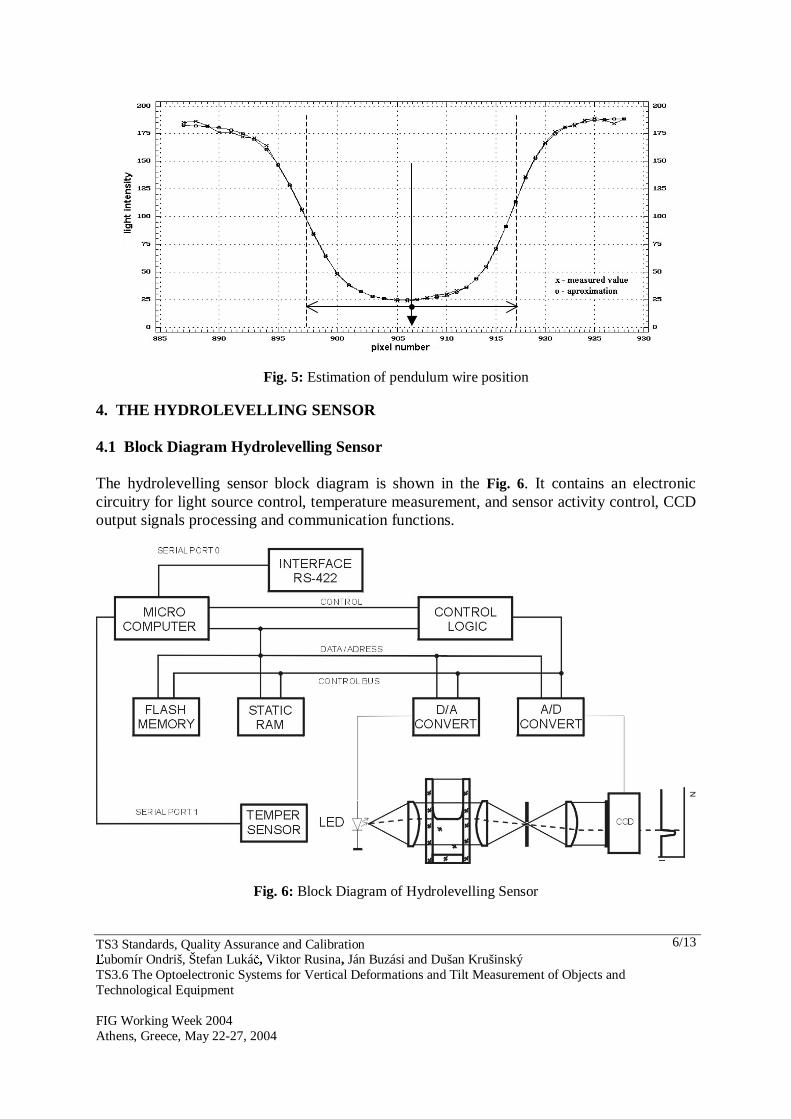
Fig. 3: Estimation of liquid level height by non linear regression 3.2 The Pendulum Wire Position in the Pendametric Sensor Fig. 4. shows a situation with uniaxial illumination of the opaque wire with a circular cross-section by the parallel light beam. The measured photometric profile on the CCD sensor pixels is depicted on the same figure. In this case is sufficient a linear regression of both transitions in illumination function for wire center position determination in one axis. The same method is used for wire position determination in the second axis. The tilt vector is determined from distance of pendulum hanging point from reference plain in which the wire position was measured, and from measured deflection in both axes.
Fig. 4: Parallel light beam passing through the sensor measurement space with pendulum wire
dhce
abI)(1 −+
+=
I - light intensity h - horizontal coordinate a - difference between min. and max. b - minimum of light intensity c - inflex point position - level position d - slope of the light intensity curve For non linear regression used Marquard-Levenberg algorithm
TS3 Standards, Quality Assurance and Calibration Ľubomír Ondriš, Štefan Lukáč, Viktor Rusina, Ján Buzási and Dušan Krušinský TS3.6 The Optoelectronic Systems for Vertical Deformations and Tilt Measurement of Objects and Technological Equipment FIG Working Week 2004 Athens, Greece, May 22-27, 2004
6/13
Fig. 5: Estimation of pendulum wire position
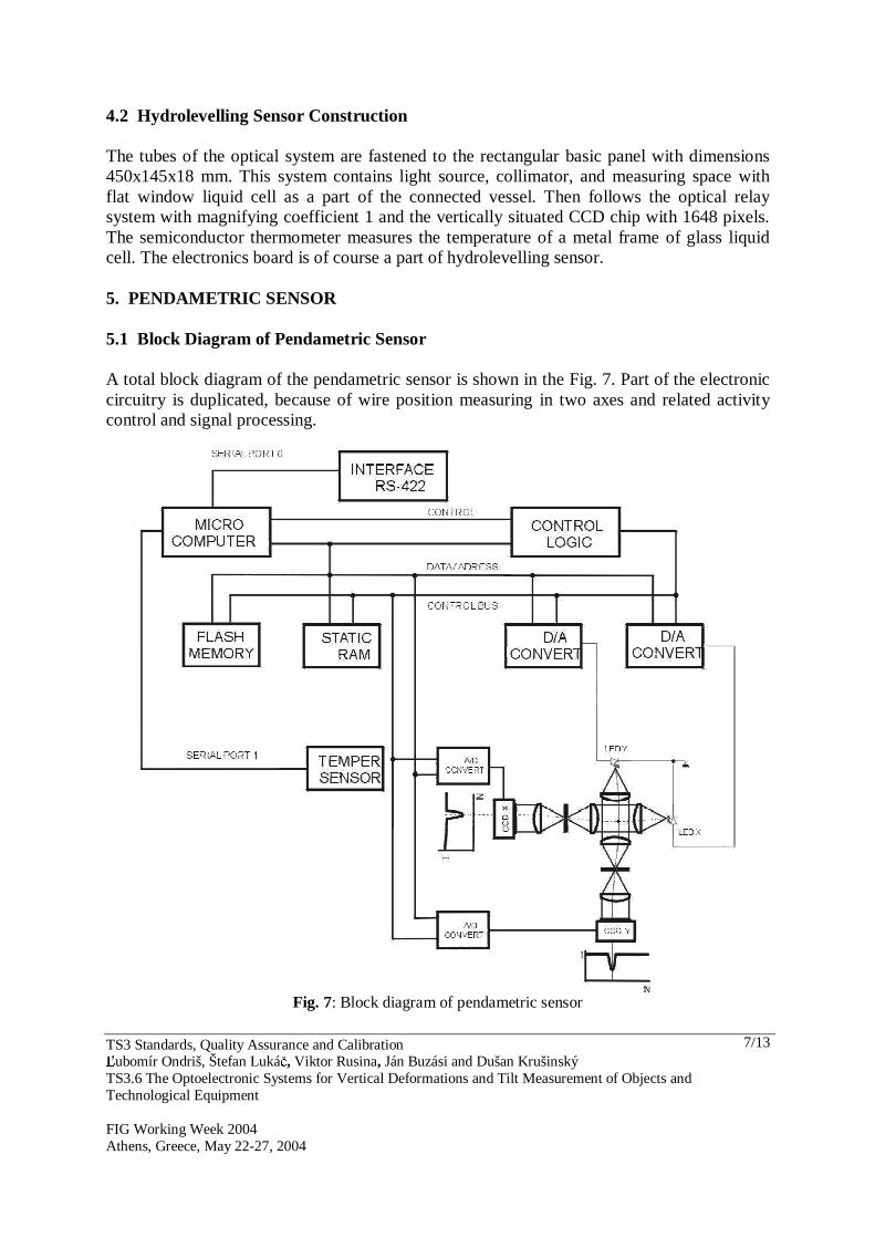
4. THE HYDROLEVELLING SENSOR 4.1 Block Diagram Hydrolevelling Sensor The hydrolevelling sensor block diagram is shown in the Fig. 6. It contains an electronic circuitry for light source control, temperature measurement, and sensor activity control, CCD output signals processing and communication functions.
Fig. 6: Block Diagram of Hydrolevelling Sensor
TS3 Standards, Quality Assurance and Calibration Ľubomír Ondriš, Štefan Lukáč, Viktor Rusina, Ján Buzási and Dušan Krušinský TS3.6 The Optoelectronic Systems for Vertical Deformations and Tilt Measurement of Objects and Technological Equipment FIG Working Week 2004 Athens, Greece, May 22-27, 2004
7/13
4.2 Hydrolevelling Sensor Construction The tubes of the optical system are fastened to the rectangular basic panel with dimensions 450x145x18 mm. This system contains light source, collimator, and measuring space with flat window liquid cell as a part of the connected vessel. Then follows the optical relay system with magnifying coefficient 1 and the vertically situated CCD chip with 1648 pixels. The semiconductor thermometer measures the temperature of a metal frame of glass liquid cell. The electronics board is of course a part of hydrolevelling sensor. 5. PENDAMETRIC SENSOR 5.1 Block Diagram of Pendametric Sensor A total block diagram of the pendametric sensor is shown in the Fig. 7. Part of the electronic circuitry is duplicated, because of wire position measuring in two axes and related activity control and signal processing.
Fig. 7: Block diagram of pendametric sensor

TS3 Standards, Quality Assurance and Calibration Ľubomír Ondriš, Štefan Lukáč, Viktor Rusina, Ján Buzási and Dušan Krušinský TS3.6 The Optoelectronic Systems for Vertical Deformations and Tilt Measurement of Objects and Technological Equipment FIG Working Week 2004 Athens, Greece, May 22-27, 2004
8/13
5.2 Pendametric Sensor Construction Two optical systems with mirror refracted light beams are fastened to the square shape basic panel with dimensions 275x275x18. These systems consist from collimated light sources, common measuring space, optical relay systems with magnifying factor 5 and horizontally situated CCD chips the same type as in hydrolevelling case. 6. MEASURING SYSTEM CONFIGURATION The both above described independent methods can be combined for measurement reliability enhancement. Such a redundancy makes possible obtain more information’s about an object behaviour, as the measured object must not be a monolithically solid body. The measuring system configuration depends on goals of measurements and also measured object character. The system of nuclear reactor tilt measurement is schematically shown in fig. 8. The system uses three hydrolevelling sensors, which are sufficient for tilt plane determination. Part of the system can be also a compensatory vessel with liquid reserve. The system contains also two biaxial pendametric sensors as useful redundancy.
Fig. 8: Measuring system configuration
7. APPLICATIONS OF HYDROLEVELLING AND PENDAMETRIC MEASURING
SYSTEMS Both above described measuring systems are successfully used in nuclear power plants Jaslovské Bohunice a Mochovce in Slovakia for nuclear reactor objects tilt monitoring. They serve for continual measurement, results presentation and archivation of a tilt data for two reactors of Jaslovske Bohunice power plant and two reactors of Mochovce power plant. This is a contribution to the extension of the operational safety in the production blocks technological process. Developed measuring systems were used in the international scientific cooperation also for height position measurement of the Nuclotron superconducting magnets, in Joint Institute for Nuclear Researches, Dubna, and Russia. This measuring system is depicted in the Fig. 9. The 25 hydrolevelling sensors, located on the circular accelerator magnets create it. The Nuclotron accelerator perimeter is 251,5 m. Part of this system is also communication system and application software.

TS3 Standards, Quality Assurance and Calibration Ľubomír Ondriš, Štefan Lukáč, Viktor Rusina, Ján Buzási and Dušan Krušinský TS3.6 The Optoelectronic Systems for Vertical Deformations and Tilt Measurement of Objects and Technological Equipment FIG Working Week 2004 Athens, Greece, May 22-27, 2004
9/13
Fig. 9: Measuring system for Nuclotron accelerator
8. MEASURING SYSTEM METROLOGICAL PARAMETERS The calibration of developed hydrolevelling and pendametric sensors was carried out by two methods. The standard method was based on vertical shift of one sensor towards another one, in case of hydrolevelling. The elevation was calculated as difference of both sensor readings. The short wire, fastened in holder, was horizontally shifted using a precise cross-table in the case of pendametric system calibration. A precise incremental measuring device with measuring accuracy 0,001 mm was used. The alternative method was using precise optical grids with known geometry, inserted into the measuring space. The optical grids were manufactured photolithographically. Reached metrological parameters are shown in table.

TS3 Standards, Quality Assurance and Calibration Ľubomír Ondriš, Štefan Lukáč, Viktor Rusina, Ján Buzási and Dušan Krušinský TS3.6 The Optoelectronic Systems for Vertical Deformations and Tilt Measurement of Objects and Technological Equipment FIG Working Week 2004 Athens, Greece, May 22-27, 2004
10/13
Hydrolevelling measuring
system Pendametric measuring
system Measuring range ± 10 mm ± 2 mm Accuracy of measurement 0,01 mm 0,005 mm Resolution 0,001 mm 0,001 mm Temperature range 0 − 40 °C 0 − 40 °C 9. CONCLUSION The long-term stability of reached metrological parameters and high measurement accuracy was achieved as a consequence of using an optoelectronic method for object vertical deformations and tilt measurement. The reached measurement accuracy is practically one order better, than accuracy reached with precise geometrical leveling. The multiprocessor sensor systems, developed in Institute of Measurement Science Slovak Academy of Sciences are working fully automatically with minimum request on service. Software of central PC assigns a user comfort and possibility of modifications according to measurement specifications. It is good in a tabular graphic measurement results interpretation. Presented measuring systems stood the test of time in operational measurements of large objects. It is possible to use them also for diagnostic measurements, where is necessary to measure for example consistency of constructions, deformations of capital buildings in industrial and constructional environment. Both used measuring methods are relative, but if the initial object state is found out by the absolute method, there is possible to pass to the absolute measurements using described methods. The systems described here were developed in the Institute of Measurement Science Slovak Academy of Sciences in cooperation with Department of Surveying, Slovak Technical University. REFERENCES Bujukjan S., Vasjutinskij I., 2003:Videomeasuring Hydrostatic System, TS 22 Surveying in
Industry and Construction, FIG Working Week 2003, Paris. Ondriš Ľ., et al., 1994: An Optoelectronic Hydrolevelling System, Meas. Sci. Technol 5, pp.
1287 –1293. Ondriš Ľ., et al., 1998: A Hydrolevelling System With Distributed Inteligence for the
Nuclotron Accelerator, Nuclear Instruments and Methods in Physics Research A, pp 513 - 522, Amsterdam, Elsevier Science.
Vasjutinskij I.,1983 : Hydrostatic Levelling,( monography in Russian) 180 p. Moskva, Nedra 1983.

TS3 Standards, Quality Assurance and Calibration Ľubomír Ondriš, Štefan Lukáč, Viktor Rusina, Ján Buzási and Dušan Krušinský TS3.6 The Optoelectronic Systems for Vertical Deformations and Tilt Measurement of Objects and Technological Equipment FIG Working Week 2004 Athens, Greece, May 22-27, 2004
11/13
BIOGRAPHICAL NOTES Ľubomír Ondriš was born in Bratislava, Slovakia in 1935. Graduated from the Faculty of Electrical Engineerig, Slovak Technical Univesity, from radioelectronic branch, in 1958. He worked as a research engineer at the Electrical Institute, Slovak Academy of Sciences. In 1965 he joined the Joint Institute for Nuclear Research Dubna, Russia and received PhD. degree in electronic engineering, in 1970. His work included solving of spectrometer for nuclear particles time of flight measurement and associated electronic equipment. In 1983 he collaborates on the building of first computer network in Czechoslovakia. His reach experience in electronics and information technology was used in first generation of original measurement system for hydrostatic levelling and pendametry in 1985. He is the author of optoelectronic method of unified position measurement of measuring element for hydrostatic levelling an pendametry in 1994. In recent time, he has participated in the development of novel method and system for space parameters measurement of nuclear particle beams. At presents he works in applied measurement laboratory, department of optoelectronic measuring methods, Institute of Measurement Science, Slovak Academy of Sciences. He holds an Outstanding Achievement Award of Slovak Academy of Science, Aurel Stodola gold medal, received in 2000 for work in the area of technical sciences. Štefan Lukáč born in Slanec, Slovakia, in 1951. Education: (1970-1975) Slovak University of Technology in Bratislava, Faculty of Civil Engineering, specialisation: Geodesy and Cartography. He attained the Certificate of authorised surveyor for engineering surveying in 1997. Professional experience: Since 1975 he performed and managed the surveying works mainly in the engineering geodesy, since 1978 he is employed as an assistant lecturer at the Department of Surveying at the Faculty of Civil Engineering, Slovak University of Technology in Bratislava, where he gives lectures in subjects as Surveying in Industry and Professional Standards in Geodesy and besides the pedagogical, scientific and publication activities (more than 120 publications) oriented mainly to the field of geodetic works in investment construction, technical specifications and standards, performs also surveying works in engineering geodesy for external customers. Membership in professional organisations: since 1997 he is the President of Slovak Union ofSurveyors, since 1997 a member of the Directive Board of Chamber of Surveyors and Cartographers and since 2002 a Vice Chairman of Chamber Board. He is also a national delegate of the Slovak Republic for the 1st Commission of FIG since1998 and a national delegate of the Slovak Republic for the 6.1st Commission of FIG. Viktor Rusina born in Bratislava, Slovakia, in 1940. Graduated from the Faculty of Electrical Engineering, Slovak Technical University, Bratislava from Radio Technology Materials Engineering branch, in 1963 and absolved postgraduate study of Patent Engineering in 1975. From 1973 to 1985, he worked as a specialist in the standartisation, metrology, quality testing and information technology area in the Czechoslovak Federal Institute. His past research experience include electrical measurement of non-electrical quantities, sensors and instrumentation systems for different purpose. At presents he works in applied measurement laboratory, department of optoelectronic measuring methods, Institute of Measurement Science, Slovak Academy of Sciences.

TS3 Standards, Quality Assurance and Calibration Ľubomír Ondriš, Štefan Lukáč, Viktor Rusina, Ján Buzási and Dušan Krušinský TS3.6 The Optoelectronic Systems for Vertical Deformations and Tilt Measurement of Objects and Technological Equipment FIG Working Week 2004 Athens, Greece, May 22-27, 2004
12/13
Ján Buzási was born in Bratislava,Slovakia, in 1936. He received the Ing. degree in fine mechanics engineering branch from Czech Technical University, Prague, in 1961. From 1961 to 1963, he worked as a research engineer at the development department of large czechoslovak optical corporation. From 1963 to present he works in applied measurement laboratory, department of optoelectronic measuring methods, Institute of Measurement Science, Slovak Academy of Sciences. His curent research interests are in the field of opticald and related instumentation design and development. Dušan Krušinský was born in Oravský Podzámok, Slovakia, in 1943. He received the Ing. degree in physics from Faculty of Technical and Nuclear Physics, Czech Technical University, Prague, in 1967. His past research activities involved the area of radioelectronics, physical chemistry and instrumentation of nuclear technology. From 1982 to 1988 he worked as a research engineer at the Joint Institute for Nuclear Research in Dubna, Russia. He has performed research on a variety of electronic measurement and control systems with particular attention to information technology, microcontrollers etc. His recent research has been in optoelectronic measuring systems in department of optoelectronic measuring methods, Institute of Measurement Science Slovak Academy of Sciences. CONTACTS L’ubomír Ondriš Institute of Measurement Science Slovak Academy of Sciences Dúbravská cesta 9 841 04 Bratislava SLOVAK REPUBLIC Tel. + 4212 5477 4033 Fex + 4212 5477 5943 Email: [email protected] Web site: http:\\www.savba.sk Štefan Lukáč Slovak University of Technology, Department of Surveying Radlinského 11 813 68 Bratislava SLOVAK REPUBLIC Tel. + 421 2 5927 4388 Fax + 421 2 5249 4334 Email: [email protected] Web site: http://www.svf.stuba.sk/kat/GDE/
TS3 Standards, Quality Assurance and Calibration Ľubomír Ondriš, Štefan Lukáč, Viktor Rusina, Ján Buzási and Dušan Krušinský TS3.6 The Optoelectronic Systems for Vertical Deformations and Tilt Measurement of Objects and Technological Equipment FIG Working Week 2004 Athens, Greece, May 22-27, 2004
13/13
Viktor Rusina Institute of Measurement Science Slovak Academy of Sciences Dúbravská cesta 9 841 04 Bratislava SLOVAK REPUBLIC Tel. + 421 2 5477 4033 Fex + 421 2 5477 5943 Email: [email protected] Web site: http:\\www.savba.sk Ján Buzási Institute of Measurement Science Slovak Academy of Sciences Dúbravská cesta 9 841 04 Bratislava SLOVAK REPUBLIC Tel. + 421 2 5477 4033 Fex + 421 2 5477 5943 Email: [email protected] Web site: http:\\www.savba.sk Dušan Krušinský Institute of Measurement Science Slovak Academy of Sciences Dúbravská cesta 9 841 04 Bratislava SLOVAK REPUBLIC Tel. + 421 2 5477 4033 Fax + 421 2 5477 5943 Email: [email protected] Web site: http:\\www.savba.sk