the operating characteristics of twin screw extruders
TRANSCRIPT

The Operating Characteristics of Twin Screw Extruders
geometry
Material f
JOHN M . SMITH, LEON P. B. M . JANSSEN, W. L. DE KONINC:, and P. P. J. ABELN
Laboratory for Physical Technology Delft University of Technology
Delft, The Netherlands
1J
The operation of a twin screw extruder processing a powder or granular solid is reviewed. The operating variables of screw speed and barrel temperature profile interact with a number of design parameters- screw design, die geometry, feed zone geometry and with the material properties, in determining machine performance. The factors that determine output and pressure development are specified in a sequence of block diagrams. The dynamic response of an operating machine to disturbances in the steady state conditions is explained in the light of the established relationships and interpreted in conven- tional control theory terms. Attention is drawn to the impor- tance of mixing in the chambers formed by the screw channels and of the residence time distribution in determining the qual- ity of the final product.
-
INTRODUCTION n earlier publications we have presented models for I the description of the throughput characteristics of the
melt filled zone of a twin screw extruder (1) and the factors that influence the residence time distribution (2). Steady state operation is clearly governed by continuity-what goes in must come out-so that output is controlled entirely by the feeding of solid frgm the hopper to the screws. The operation of the machine is represented in a diagram (Fig. 1 ) . The only relevant design parameters are the feed zone geometry and ma- terial properties, and the only operating variable under sensible conditions is the screw speed. The other factors
properties Feed rate
Fig. 1 . Basic s teady s tate operat ing d iagram.
that control transport within the machine cannot affect the output. This scheme is necessarily an oversimplifica- tion, since the system has several points at which the momentary input and output interacts with conditions in the machine. The present paper presents an analysis of machine performance and provides a basis for the estimation of dynamics of operation.
STEADY STATE OPERATION When an extruder is working continuously under
steady state conditions, several important factors which have a bearing on operation can be identified (Fig. 2) . The primary variables are clearly the screw speed and the barrel temperature profile: in general the operator has no immediate control over anything else. The design parameters which inieract with these include the mate- rial properties and the multitude of geometric details that define the die end and screw geometries. Material properties must be understood comprehensively; not only the nature of the feedstock, i.e., whether granular or powder, but also its frictional coefficient; melting characteristics and properties linking stress with flow; viscosity, elasticity and adhesion, all as functions of tem- perature and pressure. Die geometry naturally estab- lishes the relationship between the output, local fluid rheology and the pressure development at the die inlet. Screw geometry must take into account possible differ- ences between the filling zone and the melting and pumping zone.
An extruder is represented diagrammatically in Fig. 3. The solid supplied from the hopper partly fills the screw channel-in operational equipment the filling fraction (x) usually lies between 35 and 85 percent. Near the die the chambers are completely filled, and in that region the volumetric displacement rate of the screws is usually greater than the output volume rate. The d&er-
660 POLYMER ENGINEERING AND SCIENCE, JUNF, 1978, Yo/. 18, No. 8

The Operating Characteristics of Twin Screw Extruders
Screw L
geometry
-
Feed zone Feed rate geometry hopper to screws
profile rheology
Pressureat gradient bet. chambers geometry die inlet
Fig. 2. Interactions in steady state operation.
\. . . .q I
zone
melt ing
Fig. 3. Simplijied representation of a working twin screw ex- truder.
ence between these corresponds to a return leakage flow which, in screws of a uniform profile, must equal in volume the void fraction of the solids conveying zone.
v o = V f h - V L = x ' v t h
In terms of formulae we can write:
(1)
Q t h = 2 NmV (2)
where the volumetric displacement rate is
in which N is the screw speed (s-'), m is the number of
thread starts per screw and V the volume of one of the C shaped chambers that provide the conveying action.
The leakage flow, QL, takes place through the identi- fiable gaps, over the flights, calander-like through the flight-root gap, through the curved tetrahedral spaces between the flight walls and through any equatorial gaps between the sides of the intermeshing flights (1). The total backflow is in part driven by the inter-chamber pressure differences, but direct conveying by the mov- ing surfaces can also be significant, particularly for the calendar gap between counterrotating screws or through the tetrahedal gap with corotating screws. It is clear that in the solids-conveying part of the screw, where the channels are partly filled only, there is little or no axial pressure gradient, the continued interruption of the screw channel by the flights of the opposing screw ensuring that inter-chamber effects are minimized. Over the fluid-filled length the pressure rises to that at the die entry. In an absolutely uniform screw system with an isoviscous Newtonian fluid this pressure development along the screw would be linear, as represented in Fig. 4 (3).
The melting process in a twin screw extruder is very rapid-usually clearances are small enough to prevent solid migration between chambers and once liquid is present and flowing effectively countercurrent to the moving solid bed, the transition to a liquid phase is completed in little more than a single chamber. This means that we can reasonably consider zones of solids conveying and melt pumping as being sharply differ- entiated.
The relationships that can be established for steady state operation are illustrated in the diagram (Fig. 2 ) . Making the assumption that behavior in the filling zone is straight-forward, i.e., the fractional filling, x, of the screw feed section is independent of screw speed, and coupling this with the approximation of Newtonian isoviscous fluid behavior, we can make the following deductions:
1. Output (and likewise the leakage flows) will be linearly proportional to screw speed.
i 1 Filled length I IDieI -
Fig. 4 . Steady state operation, simplijied axial pressure profiles. A . Given screw speed N , die resistance 1 lc'; B . Same screw speed N , die resistance hnlved 1 1 2 ~ ' ; C. Haloed screw speed N , original die resistance 1 lc'.
POLYMER ENGINEERING AND SCIENCE, JUNE, 1978, Vol. 18, No. 8 661
John M . Smith, Leon P . B . M . Junssen, W. L. de Koning, and P . P. J . Abeln
2 . The developed pressure will be linearly propor- tional to output.
3. Since the leakages vary linearly with screw speed, so will the pressure gradient, and it follows that the number of filled chambers (usually also the position of the melt front) will be independent of screw speed, but would ofcourse be affected by changes in die geometry. 4. Under normal operating conditions the melt/
chamber filling front will lie somewhere between the hopper feed port and the die head. With an open dis- charge there would be no melt build up, no pressure development and no homogenization of the melt. With a blocked discharge, if melt is forced back along the screws as far as the hopper port, then the feeding opera- tion would be seriously disrupted. In the light of these restrictions, coupled with the fact that in a twin screw extruder we have to consider the material as being con- veyed by discrete chambers within the screw profile, then it is clear that the pressure development at the die entry can have no influence on the feeding mechanism whatsoever. This implies that it is the output that de- termines the generated pressure and not vice-versa.
The only feedback is completed by the connection between the number of filled chambers and the fluid rheology and strictly speaking the isoviscous fluid as- sumption negates this. When the material has a strong time and temperature dependence in the flow proper- ties this link could be quantified to give indication of behavior: in fact the temperature gradients in the liquid-from the just molten conditions at the melt front to the highest temperatures reached at the die entry- will usually affect the viscosity to a much more sig- nificant extent than any probable non-Newtonian ef- fects. However to a first order even this can be ignored and the simple model used to provide direct answers to design questions (4).
However plausible the reasoning that leads to the system diagram presented in Fig. 2, it cannot be pre- tended that it reflects reality, even within the assump- tions explicitly named, since number of full chambers need not, at a given moment, correspond to the predic- tion of the steady state model. The hopper to screw transfer and filling process is not exactly reproduced on each revolution of the screw after all. Any resulting imbalance can only correct itself by either pumping out the excess or allowing extra chambers to fill. This defines the essential weakness of considering only steady state factors.
THE CHAMBER-FILLING MECHANISM
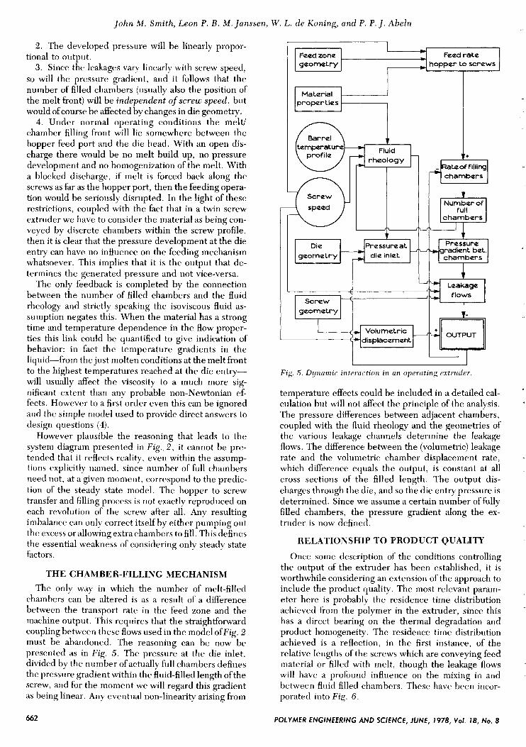
The only way in which the number of melt-filled chambers can be altered is as a result of a difference between the transport rate in the feed zone and the machine output. This requires that the straightforward coupling between these flows used in the model ofFig. 2 must be abandoned. The reasoning can be now be presented as in Fig. 5. The pressure at the die inlet, divided by the number of actually full chambers defines the pressure gradient within the fluid-filled length of the screw, and for the moment we will regard this gradient as being linear. Any eventual non-linearity arising from
* c Feud rate
hoppur to screws
Barrul
profilu
I Prussuruat die inlet
radiint but.
I --
Volumutric
Fig. 5. Dynumic interuction in an operating extruder
temperature effects could be included in a detailed cal- culation but will not affect the principle of the analysis. The pressure differences between adjacent chambers, coupled with the fluid rheology and the geometries of the various leakage channels determine the leakage flows. The difference between the (volumetric) leakage rate and the volumetric chamber displacement rate, which difference equals the output, is constant at all cross sections of the filled length. The output dis- charges through the die, and so the die entry pressure is determined. Since we assume a certain number of fully filled chambers, the pressure gradient along the ex- truder is now defined.
RELATIONSHIP T O PRODUCT QUALITY
Once some description of the conditions controlling the output of the extruder has been established, it is worthwhile considering an extension of the approach to include the product quality. The most relevant param- eter here is probably the residence time distribution achieved from the polymer in the extruder, since this has a direct bearing on the thermal degradation and product homogeneity. The residence time distribution achieved is a reflection, in the first instance, of the relative lengths of the screws which are conveying feed material or filled with melt, though the leakage flows will have a profound influence on the mixing in and between fluid filled chambers. These have been incor- porated into Fig. 6.
.
662 POLYMER ENGINEERING AND SCIENCE, JUNE, 1978, VoI. 18, No. 8

The Operating Characteristics of Twin Screw Extruders
Feed zone geometry hopper to screws
in ruii chambers
rheolog y
chambers I
I chambers I I 1
I l i 1 Preswre at Fressure
die inlet chambers
L i Leakage
I flows screw
geometry
:
Fig. 6. Interactions affecting product q u d i t y .
Mixing within a chamber is clearly affected by the screw geometry and speed, fluid rheology and the leak- age flows. This last is particularly dimcult to handle since it is known that the future history of a given leak stream (e.g., that through the tetrahedron gap) is dependent on the other gaps, in particular whether the calender gap is significant (2). It seems probable that a successful mixing model of the extruder will be based on presuming a degree of segregation within the chambers. We have of course to deal with a laminar flow and the strongly developed flow to and fro within a chamber has been shown to contain isolated regions that diffuse very slowly. The final link between the residence time distri- bution, mixing in the full chambers and product quality remains to be established. With extended knowledge of the processing history of the material that finally dis- charges through the die head it will be possible to pre- dict such properties as striation thickness or thermal degradation. Even with that information we are far from establishing that the product will be satisfactory for any arbitrary application, or that it has been made in the most economical way, but those problems are seen as being outside the scope of the present work.
EXTENSION OF THE MODEL IN TERMS OF A CONTROL DIAGRAM
In the previous paragraphs the working of the ex- truder has been considered qualitatively in engineering diagrams in which the influence of the different physical mechanisms on each other is given. In order to obtain more quantitative knowledge it is sensible to transform this diagram to a control diagram according to the con- ventions generally used in process dynamics and control (e.g., Johnson (5) and Johnson and De Koning (6)). However, it must be realized that giving a complete
description of the processes in a twin screw extruder, including heat transfer and mixing, would be too exten- sive within the context of this work. Therefore as a basis for the analysis, the diagram as gwen in Fig. 5 is chosen without taking the temperature effects into account, assuming that the melt has Newtonian behavior with a temperature independent viscosity. With these as- sumptions a dynamic system diagram can be-derived and is given as Fig. 7. Here N represents the screw speed, Q t h , Qi, Qo and QL are the positive displacement capacity, the feed, the output and the leakage flow rates respectively, vF is the number of fully filled chambers, A€' is the pressure difference between two consecutive chambers and P d is the die pressure. The transfer func- tionsfl tof7 follow from the theory and are derived from equations published previously (1; 2), see Appendix A. They can be assumed as:
Pd
VF f 3 : AP = -
(9)
Here A' and B' are proportionality constants, a' is a feed factor, C ' represents the inverse of die resistance, P d is the die pressure and Qi and Q o are the inflow and the outflow of the extruder. From E q 9 the number of fully filled chambers in the steady state can be found.
Combination of this equation with Eys 3 , 4 , 6 and 7 leads to
dvF - a' N -.2NmV + A' AP + B' N --
dt (V - a ' I2m) (10)
The pressure difference between two consecutive chambers follows from E q s 4 8
2NmV - B' N AP = A' + VF c' Since for steady state operations
the combination of E q s 8 and 9 gives after rewriting
N I Pd
Fig. 7. System diagram in control terms.
POLYMER ENGINEERING AND SCIENCE, IUNE, 7978, Vol. 78, No. 8 663

John M . Smith, Leon P. B . M . Janssen, W. L. de Koning, and P . P . J. Abeln
- A ' d vF,s - - C: 2mV - B' - a;
In these formulae the subscript s indicates steady state values. If we limit considerations to small variations in the extruder operation, these functions can be linearized. After rewriting the system variables (pi, Q t h ,
Q L , Q,, p d , AP, N , vF, a' and C ' ) as a steady state value plus a perturbation, E q s 3-9 can be rewritten after linearization as:
where the A indicates a deviation from the steady state value. Since these equations are interdependent, one of the variables can be eliminated, for instance the pertur- bation in the pressure difference between two consecu- tive chambers
2mV - B' - a: 2mV - B' - a; AN - A' 2mV - B' A(AP) =
N S AC! - (27nV - B' - C; N , AvF C,' A (2mV - B ' ) A2
Substitution of this equation into Eq 20 gives, after recombination with Eqs 14, 15,17and18, the difference equation that describes the change of the number of fully filled chambers, due to changes in the die resist- ance, the feeding process and the screw speed:
-- - A, Au,. + b, AN + hz ha' + b, AC' dt
(22)
where Ai , b, , b2, b, represent
(2mV - B' - a,;)' 2mV - B'
2mNs C i A' (2mV - a;)
A . = -
b, = 0
2mN, 2mV - a;
b2 =
(26) 2mV - B' - a: 2mNs a$
b, = 2mV - B' C i (2mV - a,;)
Defining an input u - as
- u = (21) AC'
and combining Eqs 24-26 to an input matrix B i
Eq 22 can be rewritten as
- Ai Avp + Biu -
-- - at
This equation can be represented as a diagram shown in Fig. 8.
Now that the dynamics of the number of fully filled chambers in the extruder are known, these have to be related to the other variables as for instance die pressure and output rate. From the linearized Eqs 14-20 the out- put variables can be deduced similarly. Choosing as output vector:
y = p;) (30)
the output matrix A,, becomes
N , Ci (2mV - B' - a;)' (2mV - B ' )
and the matrix B ,
a; N , (2mV - B' - a:) (2mV - B ' )
- a:2 N , Ci2 (2mV - B ' )
\ o 0 0 (32)
(33)
The output equation can be rewritten as
y =: A, A v ~ + B , u -
which can be represented by Fig. 9. Combination ofEqs 29 and 33 (which implies also the combination of the
U Fig. 8. Relationship between the number of full chumbers und the input u. -
Fig. 9. Relationship between the number of full chumbers, the input u - und the output y.
..
664 POLYMER ENGINEERING AND SCIENCE, IUNE, 1978, Vol. 18, No. 8

The Operating Characteristics of Twin Screw Extruders
Figs. 6 and 7) gives the standard state-space model of a twin screw extruder as represented in Fig. 10. For con- venience this figure can also be drawn with all influences separately (Fig. 1 1 ) .
From this dynamic model some interesting conclu- sions can be drawn. From control theory (e.g., Johnson and De Koning (6)) it follows that the time constant with which the system approaches a new steady state situa- tion is
1 - A' (2mV - 23') (2mV - a:) O d = - , l - 2mN, Cg (2mV - B' -
(34) From this equation it can be concluded that the time constant of the extruder for any disturbance is propor- tional to the die resistance and inversely proportional to screw speed. Its magnitude is generally of the order of one or more minutes.
However it must be realized that these calculations reflect only the response of the fully filled zone. In order to obtain the response of the total extruder to a distur- bance in the input a certain dead time has to be added. This reflects the time needed to transport a disturbance from the hopper through the part where the extruder is only partially filled to the fully filled zone. In general, this dead time is much shorter than the response time of the extruder and for these estimations of this response it has been neglected.
From the standard state-space model as given in Eqs 29 and 33 the response of the output variables (Po, P d and vF) to disturbances in the output variables ( N , a' and C) can be derived. The machine is supposed to operate at steady state, but at a certain moment (t = 0) a distur- bance in one of the input variables is imposed.
As a first example, a change in rotational speed is assumed (Fig. 12). It follows from the model that the
U -
w Fig. 10. Combination of Figs. 8 and 9,
A v *
r - - - - --- ~
- L.. . . . - A
Fig. 1 1 . Relationships f o r the total system deriued f r o m Fig. 5.
1" 11 - t
" I I 0 -----
-t.
-t I
-t I Fig. 12. Responses to a change in screw speed.
number of fully filled chambers does not alter. This means that no change of the hold-up of polymer in the extruder occurs and therefore the output and the die pressure follow the changes in the screw speed instan- taneously.
As a second example, some disturbance in the feed can be considered causing less material to be supplied from the hopper than is leaving the extruder as output. From Fig. 13 it can be seen that chambers will empty with the same exponential time constant as that of the system. This is connected with a similar behavior of the output, which slowly approaches its new (lower) steady state value. In the beginning the effect of decreasing feed will be compensated for by the extra material that is discharged because of the the emptying of the cham- bers. Since no change in die geometry occurs the pressure at the die inlet will change synchronously with the output.
Aa t I
-t.
Fig. 13. Responses to a change in feed rate at constant screw speed.
POLYMER ENGINEERING AND SCIENCE, JUNE, 1978, Vol. 18, No. 8 665

John M . Smith, Leon P. B . M.Janssen, W . L. de Koning, and P . P . J . Abeln
The influence of the last input variable, the die geometry, is shown in Fig. 14 . A partial die blockage will give rise to a higher die resistance which can be expres- sed by a decrease in the variable C ' . Die blockage will instantaneously increase the pressure development and so the leakage flow, and so reduce output. While operat- ing with less output than input, material will begin to pile up and the fully filled length will increase. As that happens the pressure gradient between the chambers will fall, slowly reducing the leakage flows and eventu- ally bringing the output back to the stable (initial) value. This increasing output is associated with an increasing die pressure as show in Fig. 12.
It can be seen that for normal applications, control can be best achieved either by varying the screw speed or by controlling the feed. Screw speed control has an instan- taneous effect on output and developed pressure, but may be expensive to install. Feeder control on the other hand may be relatively simple to implement, but has the disadvantage of providing a slower response, and the transport lag which has been neglected in the analysis presented here may be important.
APPENDIX A
Leakage Flow Equations The most complex relationships in the system are
those that determine the leakage flows (4). These can be summarized as follows for counter-rotating screws; Fig- ures A1 and A2 define the notation.
Through the tetrahedron gap 1 .R
Q T = 0.0054 (-$)
Through the flight gap
A'S s 6" 6qP
+- [3q (K - B) + PAP] (A-2)
4" I -t
I 1
ed -I,
Fig. 14. Respo1ise.y to (I chungc in die resi.stance a t constant screu speed.
Fig. A l . Cross sec t ion through screcs.
+I
I R
I +-B+
Fig. A2. Details of screw profiles geometrtj
Through the calander gap
A P d 3m
Qc =
, + W 4 2 R - H ) a} (A-3)
and across the side gap
(Is = r W ( 2 R - H ) (If - a) ( E + a tan Q) AP(H - a) ( E + a tan Q)3 cos2 Q +
a 24qR sin - 2
E + a tan Q [l - 0.630 - a cos2 Q
E + a tan Q + 0.052 ( - a cos2 $ 1 5 1 (A-4)
These equations, which rest on a judicious combination of analysis and empiricism, combine to give a total leak- age flow in the form
(11, = (IT + + Vr + Q s = AAP + B N (A-5)
in which AP is the pressure difference between succes- sive chambers (i.e., froin one to that adjacent to it on the other screw) and N the screw speed. Numerical values for the constantsA and B follow from the use of the screw geometric parameters in Eqs (A-1 )-(A4).
The other term which is needed is the individual chamber volume. This is again a rather cumbersome calculation, limited in accuracy only by the screw design
666 POLYMER ENGINEERING AND SCIENCE, JUNE, 1978, Vol. 18, No. 8

The Operating Characteristics of Twin Screw Extruders
parameters. For a screw pair with m thread starts, the volumeV is given by
S m v = - {(* - 5) R2 + ( R -
- 2,{ ( R H - T) H2 B + ( R H ~ - 2 ~ 3 ) tan +} (A-6)
NOMENCLATURE Apart from the geometric variables defined in Figs.
AT andA2, m = number of thread starts per screw N = screw speed, s-‘ S = screw pitch length, m Q = volumetric rate, m3s-* Q(. = leak through calender gap Q F = leak over flight gap Q1 = input = transfer from hopper to screw Q1, = total leakage
Qs = leak through side gap Q:r = leak through tetrahedron gap
Q() = output
Q f h = theoretical positive displacement ( E q 4 ) V x
vF A’
B ‘ C’ a’ = Q i / N , m3
= volume of one c-shaped chamber, m3 = filling fraction in solids conveying zone of a uni-
= number of full chambers = pressure gradient dependent part of total leak
= drag flow part of total leak flow, m3 = reciprocal of die resistance, m5/Ns
form screw
flow, m5/Ns
REFERENCES 1. L. P. B. M. Janssen, L. P. H. R. M. Mulders, and John M.
Smith, Plust. Polym., 43, 93 (1975). 2 . L. P. B. M. Janssen and John M. Smith, Proc. Conf. on Poly-
mer Rheology and Plastics Processing, p. 160, (Plastics and Rubber Inst., London) Loughborough (Sept. 17-19, 1975).
3. L. P. B. M. Janssen, J. J. Pelgrom and John M. Smith, Kunststoffe, 66, 724 (1976).
4. L. P. B. M. Janssen, “A Phenomenological Study on Twin- Screw Extruders,” Dissertation, Delft University of Tech- nology, Delft (1976).
5. A. Johnson, “Elementary Process Dynamics and Control,” Part 1, Delftse Uitgeversmij., Delft (1976).
6. A. Johnson and W. L. d e Koning, “Elementary Process Dynamics and Control,” Part 2, Delftse Uitgeversmij., Delft (1977).
POLYMER ENGINEERING AND SCIENCE, JUNE, 1978, Vol. 18, No. 8 667