the next generation space telescope : proceedings of a - stsci
TRANSCRIPT

m^f.
THE NEXT GENERATIONSPACE TELESCOPE I Mr
Simulated images

Cover: Two simulated images by James Gunn illustrate the improvements in resolution
and sensitivity that the NGST would give when compared to the Hubble Space Telescope.

TELESCOPE iVJASASCIENCE National Aeronautics and
INSmUTE Space Administration
THE NEXT GENERATION SPACE TELESCOPE
Proceedings of a Workshop jointly sponsoredby the
National Aeronautics and Space Admnistration
and the
Space Telescope Science Institute
and held at the
Space Telescope Science Institute
Baltimore, Maryland,
13-15 September 1989
Editors:
Pierre-Yves Bely and Christopher J. BurrowsSpace Telescope Science Institute
Garth D. Illingworth
University of California, Santa Cruz
Published and distributed by the Space Telescope Science Institute
3700 San Martin Drive, Baltimore, MD, 21218
CTK^J
' r-t
Scientific Organisation Committee:
Garth D. Illingworth (Chair), University of California
James Roger Angel, University of Arizona
Jacques M. Beckers, European Southern Observatory
James E. Gunn, Princeton University
Donald N.B. Hall, University of Hawaii
Malcolm Longair, Royal Observatory, Edinburgh
Hervey S. (Peter) Stockman, Space Telescope Science Institute
Edward J. Weiler, NASA Headquarters
Local Organisation Committee: /4^r[^TrAav>^^i Lc\o^<^<' "^
Pierre Y. Bely (Chair) ^ 6?6Christopher Burrows
J ^^^^ _ ^ ^.g
Barbara EUer . /
Hervey S. (Peter) Stockman ' " 1
TABLE OF CONTENTS
Foreword 1
Conclusions of the Workshop 5
Sage Advice 7
SESSION 1. INTRODUCTION AND PLANS
Sumnciary of Space Science Board 1995-2015 Study, G. Field, CFA 11
Status and Future of NASA Astrophysics, E. Weiler, NASA Headquarters . . 16
ESA Long Term Plans and Status, F. Macchetto, STScI 27
The Next Generation UV-Visible-IR Space Telescope G. Illingworth, UCSC . 31
SESSION 2. SCIENTIFIC POTENTIAL
NGST and Distant Galaxies, J. Gunn, Princeton 39
Planetary Astronomy with a Large Space Telescope, R. Brown, STScI ... 44
Star Formation Studies with a Large Space Telescope, L. Blitz, U of Maryland 49
Quasi-stellar Objects and Active Galactic Nuclei: Prospects for
a 10 meter Space Telescope, J. Miller, Lick Obs 54
Stellar Populations in Galaxies: the Scientific Potential for a
10-16 m Space Telescope, J. Gallagher, AURA 61
Quasar Absorption-line Studies with HST Successor, R. Green, NOAO ... 72
Use of 16m Telescope to Detect Earthlike Planets, R. Angel, Steward Obs. 81
SESSION 3. LARGE OPTICS: GROUND-BASED DEVELOPMENTS
The Keck Telescope Project, J. Nelson, Lawrence Berkeley Lab., UCB ... 99
Stressed-lap Polishing, H.M. Martin and J.R.P Angel, Steward Obs. . . . 101
Large Telescope 0-IR Astronomy from the Ground,
N. Woolf, Steward Obs 110
SESSION 4. CURRENT PROPOSALS AND STUDIES
Considerations for a Next Generation UV-Optical Space Telescope,
M. Nein and S. H. Morgan, NASA MSFC 117
IBIS: An Interferometer-Based Imaging System for Detecting Extrasolar
Planets with a Next Generation Space Telescope, D. Diner, JPL 133
The Large Deployable Reflector, P. Swanson, JPL 142
PAMELA: High Density Segmentation for Large, Ultra-light,
High Performance Mirrors, J. Rather et al, Kaman Aerospace Corp. . . . 147
Optical Interferometry from Space, R. Stachnik, NASA Headquarters .... 157
Direct IR Interferometric Detection of Extrasolar Planets, M. Shao, JPL . . 160

SESSION 5. TECHNOLOGIES FOR lARGE, HIGH THROUGHPUT WIDEBANDOPTICAL SYSTEMS IN SPACE
Design Concepts for Very Large Aperture, High-performance Telescopes,
D. Korsch, Korsch Optics 171
The Lunar Configurable Array Telescope (LCAT), A. Meinel/M. Meinel, JPL 177
Large Optical Fabrication Considerations and Speculation about
the Overall NGST Configuration, M. Krim, Perkin Elmer 182
Large Segmented Optics Fabrication and Wavefront Control, R. Vyce, Itek . 198
Fabrication of Large and Fast Mirrors with Extroardinary Smooth Surfaces,
D. Knohl, Carl Zeiss 209
Economical Production of Large Optics, D. Pileri and W. Prensky, Kodak . . 217
Super Smooth Optics for Extrasolar Planet Detection,
R.J. Terrile, JPL, and C. Ftaclas, Hughes 225
Sensing and Control for Large Opticcd Systems, A. Wissinger, Perkin Elmer . 232
Requirements for Diffraction Limited Optics, C. Burrows, STScI 241
Precision Segmented Reflectors (PSR), R. Lin, JPL 252
ASCIE: An Integrated Experiment to Study Control Structure Interaction in
Large Segmented Optical Systems, J-N Aubrun and K. LoreU, LMSC . . . 256
Control Structure Interaction (CSI) Technology, W. Layman, JPL 263
Pointing Control System for a 10 meter Space Telescope, D. TenereUi, LMSC 270
Moving Target Tracking for a Next Generation Space Telescope,
D. SkiUman, NASA GSFC 274
Passive Cooling of a 10 meter Space Telescope, P. Tulkoff, Swales 279
Cryogenics for Space Observatories: Technology, Requirements, Issues,
H. Schember , JPL 285
Visible and UV Detectors for High Earth Orbit and Lunar Observatories,
B. Woodgate, NASA GSFC 296
Infrared Detectors for a 10 m Space or Lunar Telescope,
R. Thompson, Steward Obs 310
SESSION 6. SPACE LOGISTICS
Advantages of High vs. Low Earth Orbit for SIRTF,
P. Eisenhardt and M. Werner, NASA Ames 321
Orbital Sites Tradeoff Study,
D. Neill, P. Bely, G. MiUer, and A. Spigler, STScI 333
The Moon as a Site for Astronomical Observatories,
J. Burns, New Mexico State U 341
Required Technologies for a 10-16 m UV-Visible-IR Telescope on the Moon,
S. Johnson and J. Wetzel, BDM Corp 348
Space Logistics: Launching Capabilities, R. Furnas, NASA Headquarters . . . 360
On-orbit Assembly and Maintenance, D. Soderblom, STScI 365
Technological Spinoff from the Next Generation, V. Trimble, UMD/UCI . . 367
List of Participants 369

FOREWORD
In Space Science in the Twenty-First Century, the Space Science Board of the Na-
tional Research Council identified high-resolution interferometry and high-throughput
instruments as the imperative new initiatives for NASA in astronomy for the two decades
spanning 1995 to 2015. In the optical range, the study recommended an 8 to 16-meter
space telescope, destined to be the successor of the Hubble Space Telescope (HST), and to
complement the ground-based 8 to 10-meter-class telescopes presently under construction.
It might seem too early to start planning for a successor to HST. In fact, we are late.
The lead time for such major missions is typically 25 years, and HST has been in the
making even longer with its inception dating back to the early 1960s. The maturity of
space technology and a more substantial technological base may lead to a shorter time
scale for the development of the Next Generation Space Telescope (NGST). Optimistically,
one could therefore anticipate that NGST be flown as early as 2010. On the other hand,
the planned lifetime of HST is 15 years. So, even under the best circumstances, there will
be a five year gap between the end of HST and the start of NGST.
The purpose of this first workshop dedicated to NGST was to survey its scientific po-
tential and technical challenges. The three-day meeting brought together 130 astronomers
and engineers from government, industry and universities. Participants explored the tech-
nologies needed for building and operating the observatory, reviewed the current status
and future prospects for astronomical instrumentation, and discussed the launch and
space support capabihties likely to be available in the next decade. To focus discussion,
the invited speakers were asked to base their presentations on two nominal concepts, a
10-meter telescope in space in high earth orbit, and a 16-meter telescope on the moon.
Artist's view of these two concepts are shown in Figures 1 and 2, and their specifications
are summarized in Table 1.
The workshop closed with a panel discussion focused mainly on the scientific case,
siting, and the programmatic approach needed to bring NGST into being. The essential
points of this panel discussion have been incorporated into a series of recommendations
that represent the conclusions of the workshop.
Speakers were asked to provide manuscripts of their presentation. Those received
were reproduced here with only minor editorial changes. The few missing papers have
been replaced by the presentation viewgraphs. The discussion that follows each speaker's
paper was derived from the question and answer sheets, or if unavailable, from the tapes
of the meeting. In the latter case, the editors have made every eflFort to faithfully represent
the discussion.
We are most thankful to all the speakers for their very thoughtful and valuable con-
tributions. Their vast experience in science and engineering wiU be essential for the
successful completion of a project of this scale. Thanks are due to Roger Angel, Jack
Burns, Don Hall, Duccio Macchetto, Joe Miller, Jean OHvier, Peter Stockman, Dominick
TenereUi, and Rodger Thompson for chairing the various sessions or for their participation
in the panel. We would also Uke to thank John Bahcall who introduced the workshop
by sharing some of his experiences with the HST project. His pertinent remarks about
the dedication of those involved in the development of HST emphasized the deep and
widespread commitment needed to bring about its successor.
We would particularly Hke to thank Riccardo Giacconi for his keen interest and sup-
port of the workshop. He had urged us for some time to think of the long-term needs of the

astrophysics community and to explore the scientific potential and technical challenges of
a successor to HST. We also greatly appreciate the support given by Peter Stockman. Hecontributed invaluable advice and assistance throughout, ensured that the appropriate
Institute resources were available, and gave an excellent summary of the meeting.
We would also Hke to extend our gratitude to Charles Pellerin for personally support-
ing the meeting and providing NASA funding for the publication of these proceedings.
This workshop is but an early step on the long journey to the completion of NGST.As evidenced by these proceedings, however, the spectacular views of the heavens to be
provided by this telescope and a deeper understanding of our universe and its origin are
a worthy destination for this complex and challenging journey.
The Editors

Table 1. Nominal Next Generation Space Telescope (NGST)

Figure 1. Artist's concept of a 10 meter telescope in high earth orbit. The telescope is
very compact thanks to a fast primary and the short baffle that a relaxation of sun, moon
and bright earth avoidance angles in high orbit permits. Solar panels are fixed on the rear
of the spacecraft to minimize mechanical disturbances.
Figure 2. Artist's concept of a 16 meter telescope on the moon. The segmented primary
mirror is supported by a hexapod mount, the legs of which are extendable for pointing and
tracking. A coude-like arrangement is used to feed the scientific instruments which are
located underground for radiation and meteorite protection. The rails are for a hangar-type
shield which is rolled over the telescope during lunar day.
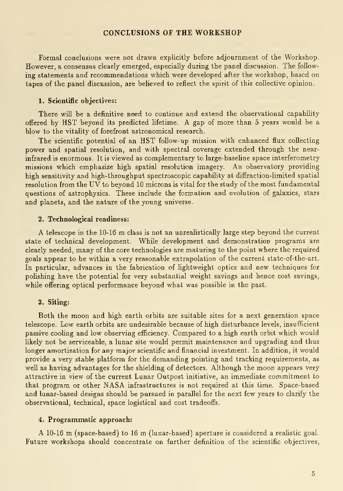
CONCLUSIONS OF THE WORKSHOP
Formal conclusions were not drawn explicitly before adjournment of the Workshop.
However, a consensus clearly emerged, especially during the panel discussion. The follow-
ing statements and recommendations which were developed after the workshop, based on
tapes of the panel discussion, are beheved to reflect the spirit of this collective opinion.
1. Scientific objectives:
There will be a definitive need to continue and extend the observational capability
offered by HST beyond its predicted hfetime. A gap of more than 5 years would be a
blow to the vitaUty of forefront astronomical research.
The scientific potential of an HST follow-up mission with enhanced flux collecting
power and spatial resolution, and with spectral coverage extended through the near-
infrared is enormous. It is viewed as complementary to large-baseline space interferometry
missions which emphasize high spatial resolution imagery. An observatory providing
high sensitivity and high-throughput spectroscopic capability at diffraction-limited spatial
resolution from the UV to beyond 10 microns is vital for the study of the most fundamental
questions of astrophysics. These include the formation and evolution of galaxies, stars
and planets, and the nature of the young universe.
2. Technological readiness:
A telescope in the 10-16 m class is not an unreahstically large step beyond the current
state of technical development. While development and demonstration programs are
clearly needed, many of the core technologies are maturing to the point where the required
goals appear to be within a very reasonable extrapolation of the current state-of-the-art.
In particular, advances in the fabrication of Hghtweight optics and new techniques for
poHshing have the potential for very substantial weight savings and hence cost savings,
while offering optical performance beyond what was possible in the past.
3. Siting:
Both the moon and high earth orbits are suitable sites for a next generation space
telescope. Low earth orbits are undesirable because of high disturbance levels, insufficient
passive cooHng and low observing efficiency. Compared to a high earth orbit which would
likely not be serviceable, a lunar site would permit maintenance and upgrading and thus
longer amortization for any major scientific and financial investment. In addition, it would
provide a very stable platform for the demanding pointing and tracking requirements, as
well as having advantages for the shielding of detectors. Although the moon appears very
attractive in view of the current Lunar Outpost initiative, an immediate commitment to
that program or other NASA infrastructures is not required at this time. Space-based
and lunar-based designs should be pursued in parallel for the next few years to clarify the
observational, technical, space logistical and cost tradeoffs.
4. Programmatic approach:
A 10-16 m (space-based) to 16 m (lunar-based) aperture is considered a realistic goal.
Future workshops should concentrate on further definition of the scientific objectives,

review of preliminary studies and the identification of critical technologies. Strawmandesigns should be prepared to refine the various concepts and ideas and focus discussion.
A "Telescope Design Group" should be formed to guide and oversee the preliminary
design work. This group, comprised of astronomers and technologists, should address the
scientific goals and technical requirements together, paying particular attention to system
engineering. In projects of this complexity, efficient design is the result of many compro-
mises that can only be developed by successive iterations and by system-level analyses.
The importance of this iterative process involving astronomers, physicists and engineers
in the science-engineering tradeoffs and in defining the requirements was emphasized by
many participants. The involvement of these different groups needs to occur during all
phases of the project, from concept development, through technology development andfabrication, and finally during system-level testing.
Once clearly identified by the preliminary design process, the development of the key
enabhng technologies should be integrated with the appropriate long-term program of
the national and international Space Agencies (e.g., NASA's Technology 21). This will
ensure both that the technological requirements are addressed at the proper level, and
that benefits are obtained from interaction with other programs.
5. International cooperation:
Like HST, the next generation space telescope project should be carried out coop-
eratively as an international program. Cost sharing renders such major missions moreaffordable for each participating country, and international collaboration often enhances
quaUty and performance. Complex and pioneering space missions also benefit from the
exchange of ideas and variety of approaches afforded by multicultural collaborations.
SAGE ADVICE
"International cooperation may be critical for such a major project". Bahcall
"It's not often that we have a chance to participate in history". Danielson (as quoted by
Bahcall)
"Astronomers will become addicted to HST observing". Elingworth
"In comparison to ground-based uses, adaptive optics in space should be easy". Angel
"In space, only a filled aperture telescope makes sense". Swanson
"Don't underestiniate the difficulty of achieving the required surface error". Swanson
"We should not simply accept a traditional R-C design for a 10 meter telescope". Korsch
"The more money that we put up front, the cheaper the next telescope will be". Breck-
inridge
"One of the things which should come from this workshop is a better understanding of
the merits of filled apertures and interferometers". Breckinridge
"Time is the great enemy". Krim
"I don't want you to think that 100°K is guaranteed". Schember
"I recommend that you think beyond Shuttle C for the next ST". Furnas
"On M&R, my rule of thumb is don't do it!". Soderblom
Collected during the Workshop by Pete Stockman


Session 1
Introduction and Plans

Simunary of Space Science Board 1995-2015 Study
George Field
Center for Astrophysics
1. Introduction
In 1984, NASA requested the Space Science Board to undertake a study to determine
the principal scientific issues that the disciplines of space science would face during the
period from about 1995 to 2015.^ Six Task Groups were established, including one on
Astronomy and Astrophysics, chaired by Bernie Burke. As Bernie could not be here, and
I had served on both the Astronomy and Astrophysics Task Group and the Steering Group
of the Study, I agreed to report on its activities in his absence here today. Roger Angel,
a participant in this Workshop, was also a member of the Astronomy and Astrophysics
Task Group.
2. The Space Science Board Report: Space Science in the Twenty-First Century
On page 46 of Space Science in the Twenty-First Century - Overview^ the recom-
mended program for astronomy and astrophysics is given under three headings: (1) imag-
ing interferometry, (2) large area and high-throughput telescopes, and (3) AstroMag, a
massive cosmic-ray analyzer in space. Item (2b) is an 8-16 meter optical space tele-
scope, the subject of this Workshop. The same Report, in the volume on Astronomy and
Astrophysics, 2 p. 48, states that,
"A large-aperture space telescope for the ultraviolet, optical, and infrared regions has
immense scientific potential. The need for such a telescope will be very high after 10 to
20 years of use of HST and ground-based 8- to 10-m-class telescopes. Even now we see
that some of the most fundamental of all astronomical questions will require the power
of a fiUed-aperture telescope of 8- to 16-m diameter designed to cover a wavelength range
of 912 Ato 30/im, with ambient cooling to 100° K to maximize the infrared performance.
"With the HST and SIRTF still to be launched, and the anticipated wealth of data
not yet analyzed, it is difficult but not premature to formulate a detailed concept of such
a large-scale telescope for the ultraviolet, optical, and infrared regions. This telescope
will also complement a space interferometer. The diffraction limited resolution of a 15-m
telescope is six times sharper than that of the HST; it would be far more sensitive, both
because of its greater collecting area and because of the small size of its diffraction-limited
image. The image is 1/100 arcsec in diameter for a 15-m telescope in visible light. At
this resolution the reflected zodiacal background is reached at magnitude 33, about 11
magnitudes fainter than ground-based telescopes, and four magnitudes fainter than HST.
"The large telescope would not simply be a scaled-up HST. Its infrared performance
would be optimized by cooling the optics to at least the lower limit of passive radiation
methods, about 100°K. Similarly, the optical performance would be greatly enhanced
by a wide-field optical design suitable for larger, high-resolution detector mosaics and
multiple-image spectroscopy. Images with 10^^ picture elements are possible with present
optical designs, and the technology for charged coupled device (CCD) mosaics this large
is advancing.
11

"A large range of scientific problems could be undertaken only by a telescope of this
type. The combination of light-gathering power and resolution offered by such a telescope,
equipped with advanced spectrographs and detectors, would lead to a quantum leap in
our understanding of some of the most fundamental questions in astronomy."
There follow six pages of dicussion of scientific objectives for an 8- to 16-m telescope.
On p. 55 of the same Report^ there is a section on technological developments,
including a discussion of methods for fabricating the telescope. In particular, it is stated
that,
"Two possible avenues are available for orbiting the large telescope. It seems hkely
that in the time frame under consideration large vehicles could launch a prefabricated
telescope up to 8 m in diameter. Alternatively, for a 16-m diameter telescope, construction
in orbit is probably the best route. Mirror segments would be polished and tested on the
ground and assembled onto a frame structure built in space."
"Large telescopes designed to operate in a zero-g environment, but which do not
have to withstand launch, are an exciting challenge to designers and engineers. Given
a well-directed technology development program, the task group anticipates that an 8-
to 16-meter telescope will be within closer reach than a simple extrapolation from HSTwould suggest."
Thus, the assessment of an 8- to 16-m space telescope by the Task Group on As-
tronomy and Astrophysics is relatively optimistic. It should be noted that as explained
above, the large telescope is only one of the recommended elements of the program for
astronomy and astrophysics in the 1995-2015 time frame. There are four other large-area
telescopes for submillimeter. X-ray, and gamma-ray astronomy, and three facilities for
imaging interferometry at optical and radio wavelengths, including one, the Large Space
Telescope Array of nine 1.5-meter optical telescopes mounted on a tetrahedral structure
100 m or so in diameter, aimed for milliarcsecond resolution with about 20 m^ collecting
area, about 1/4 that of the large telescope.
The Task Group briefly addressed the question of cost, and assumed (p.68) that for
each wavelength regime only one observatory class facility will operate at a time, that
new facilities will be developed soon enough to prevent the occurence of substantial gaps
in observational capability, and that new facilites will cost about twice as much as the
ones they replace. On this basis, the Task Group concluded that the base program (Great
Observatories and their replacements) can be carried out if the annual real-dollar NASAastrophysics budget increases over FY 85 at 2.3 % per year. If the large telescope is taken
to be the replacement for HST, one infers that the Task Group believes that it can be
accomplished for about $4B in 1986 dollars. I will retum to the question of cost in the
last section, below.
The Astronomy and Astrophysics Task Group wrote an Appendix entitled, "Astro-
physics at a Lunar Base," which, however, does not appear as part of its Report.
In its Overview volume,^ the Steering Group accepted the main outlines of the Task
Group Repon, including the 8-m to 16-m telescope. In chapter 9 of the Overview there
is a discussion of Human Presence in Space in which it is argued that if human presence
extends further into the solar system, brief forays of human beings to remote places are
not very useful for science. On the other hand, much useful science can be done by humans
located at various stations (earth orbit, Moon, Mars) for long periods. It concludes (p.
77) that
12

"space science experiments, tended in space by human beings, may provide the most
important rationale for the staging, assembly, maintenance, repair, and operation of ma-
jor space facilities (e.g., space astronomical telescopes, earth science experiment pay-
loads/platforms, launch vehicles for planetary missions)."
The Space Science Board Study was concluded in June, 1986, and the Report was
published in 1988.
3. The Report of the National Commission on Space: Pioneering the Space Frontier
In 1985 Congress chartered and the President appointed a National Commission on
Space of 15 members, chaired by Dr. Tom Paine, former Administrator of NASA. As a
member of the commission, I wrote the first draft of the section on space science in its
Report, Pioneering the Space Frontier, published in 1986^. I drew heavily on the Space
Science Board 1995-2015 Study^'^ discussed above. The National Commission on Space
was charged with "formulating a bold agenda to carry the civilian space program into the
21st century." Told that the Space Station should be treated as a given in its deliberations,
the Commission laid out a trillion-dollar plan that would result in a permanent Moonbase in 2005 AD and a Mars base in 2027 AD. Considerable space was given to science
generally and to astronomy in particular. On p. 9, the Reports recommends "a sustcuned
program to understand the evolution of the Universe, through astronomical facilities of
increasing power, precision, and sophistication at locations in more distant Earth orbits
and at eventual locations on the Moon."
On p. 50, it states that
"Astronomical instruments can be located in low Earth orbit, geostationary orbit,
solar orbit, or on the surface of the Moon. With a few notable exceptions, most of themhave been in low Earth orbit, and in the near future will continue to be located there
because of lower cost and direct support from the Space Station. As a lunar base is
developed, astronomers will take advantage of the ability to build rigid telescope mounts,
of the freedom from contamination by propellants, of the longer and colder nights, and of
the shielding from Earth light and radio interference which are available on the far side
of the Moon."
The recommendations of the Space Science Board 1995-2015 Study were transmuted
(p. 52) into one for
"a large space telescope array composed of 25-foot (8-m) diameter telescopes [to]
operate in the ultraviolet, visible, and infrared. The combination of large diameter tele-
scopes with a large number of telescopes would make this instrument 100 times more
sensitive than Hubble Space Telescope. Because the image would be three times sharper,
the limiting faintness for long exposures would increase more than 100 times."
This recommendation is broadly consistent with the Space Science Board recommen-
dations for both the 8- to 10-m optical space telescope and the large space telescope
array.
4. The Ride Report: Leadership and America's Future in Space
NASA Administrator Dr. James Fletcher formed a task group to define potential U.S.
space initiatives, and to evaluate them in the light of the current space program and the
nation's desire to regain and retain space leadership. Its report, Leadership and America's
Future in Space,^ published in August 1987, can be viewed as a NASA response to the
13

Report of the Rogers Commission to investigate the Challenger accident and the Paine
Commission on the future of the space program. It narrowed the field of new initiatives
beyond the current base program to four options:
(1) Mission to Planet Earth
(2) Exploration of the Solar System
(3) Outpost on the Moon
(4) Humans to Mars.
Briefly, Mission to Planet Earth would use the perspective afforded from space to
characterize the Earth on a global scale; Exploration of the Solar System would retain
U.S. leadership in the (unmanned) exploration of the outer solar system and regain U.S.
leadership in exploration of comets, asteroids, and Mars; the Outpost on the Moon would
return Americans to the Moon to continue exploration, to establish a permanent scien-
tific outpost, and to begin prospecting for resources; and Humans to Mars would send
astronauts on three round trips to land on the surface of Mars, leading to the eventual
establishment of a permanent base. In view of the fact that astronomy is not mentioned
in the Ride Report under options (1) or (2), one may surmise that the space astronomy
program would not be highlighted if they are adopted. Astronomy is mentioned under
Outpost on the Moon (p. 30), where it is stated that, "The Moon's unique environ-
ment provides the opportunity for significant scientific advances; the prospects for gains
in lunar and planetary science is abundantly clear. Additionally, since the Moon is seis-
mically stable and has no atmosphere, and since its far side is shielded from radio noise
from Earth, it is a very attractive spot for experiments and observations in astrophysics,
gravity-wave physics, and neutrino physics, to name a few." Astronomy is not mentioned
under Humans to Mars. In concluding chapters, the Ride Report recommends that NASA"should embrace the Mission to Planet Earth," that "although not necessarily at the pace
suggested in this initiative, planetary exploration must be solidly supported." The Ride
Report is not enthusiastic about an early effort to land humans on Mars, but is favorable
toward the timely establishment of an Outpost on the Moon.
Apparently the National Space Council is moving toward a decision as to which, if
any, of the Ride Report initiatives to recommend to the President. This would have
profound implications for the 10- to 16-m telescope being discussed in this Workshop. If
the choice is to retum to the Moon, one may anticipate substantial increases in the NASAbudget. Although Figures 14 and 15 on p. 46 of the Ride Report are not labelled in dollar
amounts, one can surmise that starting in the mid 90's, NASA's budget would have to
triple for either the Outpost on the Moon or the Humans to Mars programs to be carried
out. On the other hand. Mission to Planet Earth or Exploration of the Solar System
would apparently require only about a 30% increase in the NASA budget. I conclude
that in the latter case, funds available for the 8-m to 16-m telescope will be little more
than for the telescope it replaces, the HST. What might a telescope in Earth orbit actually
cost? In connection with a study of the cost of space-based laser ballistic missile defense I
carried out with David Spergel,^ I had occasion to look into the cost one might estimate
for diffraction-limited optical systems in low earth orbit, including the associated systems
for target acquisition and tracking (but not launch or maintenance). Our best estimate
for the cost of a system of aperture D (meters) was $3.6 (D/10)^-^ billion in 1984 dollars,
or $3.8 (D/10)l-7 billion in 1986 dollars, consistent with the $4B implied by the Space
Science Board Study (see above). Hence I agree that a 10-meter in low earth orbit seems
14

reasonable on fiscal grounds.
For a 16-m on the Moon the scaling law indicated above would suggest an increase
by a factor of 2.2, up to $8.4B in 1986 dollars, w^hich might be acceptable under a muchexpanded (about three-fold) NASA program driven by an Outpost on the Moon. However,there will be major cost differentials between basing in earth orbit and on the Moon.Clearly the question of cost will be vital to address as planning proceeds.
References
1. Space Science in the Twenty-First Century: Imperatives for the Decades 1995-2015.
In seven volumes; Volume I, Overview. Report of the Study Steering Group, SpaceScience Board, Commission of Physical Sciences, Mathematics, and Resources, Na-
tional Research Council (Washington, D.C.: National Academy Press), 1988.
2. Ibid.., Volume II, Astronomy and Astrophysics. Report of the Task Group on As-
tronomj' and Astrophysics, Space Science Board, Commission on Physical Sciences,
Mathematics, and Resources, National Research Council. (Washington, D.C.: Na-
tional Academy Press), 1988.
3. Pioneering the Space Frontier: The Report of the National Commission on Space
(New York: Bantam Books), 1986.
4. Leadership and America's Future in Space, by Sally K. Ride (Report to the Adminis-trator of NASA, August 1987).
5. "Cost of Space-Based Laser Ballistic Missile Defense," by George Field and DavidSpergel, Science, 231, 1387-1393 (1986).
DISCUSSION
Pilcher : There was another NASA report following the Ride Report entitled Beyond Earth's Bound-
aries, the first annual report of the Office of Exploration (OESP). OEXP was formed in 1987 at Sally
Ride's recommendation to provide an institutioned home within NASA for human exploration of the
solar system. In Beyond Earth's Boundaries, OEXP reported on a group of case studies including one
on a lunar observatory. That case study was based in part on papers presented at a series of workshops
including Future Astronomical Observatories on the Moon (held in 1986 at JSC, proceedings published
as orange covered NASA Conference Proceedings); Lunar Bases and Space Activities of the 21st Cen-
tury (held in 1984, proceedings published in 1985 by the Lunar and Planetary Institute, Houston); and
A Lunar Farside Very Low Frequency Array (held at Univ. New Mexico, Albuquerque; Proceedings
in Press).
15

Status and Future of NASA Astrophysics
Edward J. Weiler
NASA Headquarters
PART1
STATUS OF CURRENT PROGRAM
HUBBLE SPACE TELESCOPE(HST)
• FIRST OF FOUR GREAT OBSERVATORIES
• AMONG NASA'S HIGHEST PRIORITY PROGRAMS
• 2.4 METER APERTURE DIFFRACTION-LIMITED "OPTICAL" TELESCOPE
• SIX INITIAL INSTRUMENTS
FOC • WF/PC • FOSHRS • HSP • FGS
• 1150 A TO 1.1 MICRON MEASURING RANGE
• 15 YEAR LIFETIME ACHIEVABLE WITH ON-ORBIT SERVICING
CURRENT STATUS: TELESCOPE SHIPMENT TO KSC IN OCTOBER 1989; LAUNCH IN
SPRING 1990.
I
16
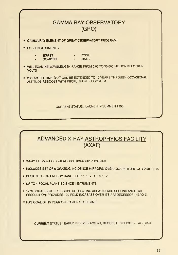
GAMMA RAY OBSERVATORY(GRO)
• GAMMA RAY ELEMENT OF GREAT OBSERVATORY PROGRAM
• FOUR INSTRUMENTS
EGRET • OSSECOMPTEL • BATSE
• WILL EXAMINE WAVELENGTH RANGE FROM 0.05 TO 30,000 MILLION ELECTRONVOLTS
• 2 YEAR LIFETIME THAT CAN BE EXTENDED TO 1 YEARS THROUGH OCCASIONAL
ALTITUDE REBOOST WITH PROPULSION SUBSYSTEM
CURRENT STATUS; LAUNCH IN SUMMER 1990
\ADVANCED X-RAY ASTRQPHYICS FACILITY
(AXAF)
• X-RAY ELEMENT OF GREAT OBSERVATORY PROGRAM
• INCLUDES SET OF 6 GRAZING INCIDENCE MIRRORS; OVERALLAPERTURE OF 1 .2 METERS
• DESIGNED FOR ENERGY RANGE OF 0.1 KEV TO 10 KEV
• UP TO 4 FOCAL PLANE SCIENCE INSTRUMENTS
• 1700 SQUARE CM TELESCOPE COLLECTING AREA; 0.5 ARC SECOND ANGULARRESOLUTION; PROVIDES 100-FOLD INCREASE OVER ITS PREDECESSOR (HEAO-2)
• HAS GOAL OF 15 YEAR OPERATIONAL LIFETIME
CURRENT STATUS: EARLY IN DEVELOPMENT; REQUESTED FLIGHT - LATE 1995
17

SPACE INFRARED TELESCOPE FACILITY
(SI RTF)
LAST OF THE GREAT OBSERVATORIES
CRYO COOLED TELESCOPE WILL EXCEED SENSITIVITY OF IRAS BY 3 ORDERS OFMAGNITUDE
THREE SCIENCE INSTRUMENTS
INFRARED SPECTROMETER (IRS)
INFRARED ARRAY CAMERA (IRAC)
MULTIBAND IMAGING PHOTOMETER (MIPS)
PRIMARILY GUEST OBSERVER PROGRAM
PLANNED LIFETIME OF AT LEAST 5 YEARS IN 100,000 KM ORBIT
CURRENT STATUS: PHASE B RFP UNDER EVALUATION; IN OSSASTRATEGIC PLAN FOR 1993 NEW START
J
ASTRO - 1 .2
• SPACELAB PAYLOAD WITH FOUR SEPARATE COMPLEMENTARY OPTICAL TELESCOPES
• THREE CO-POINTED FAR UV TELESCOPES: HUT, UIT, WUPPE
• BBXRT ON SEPARATE POINTER (TAPS)
• TOGETHER, OBTAIN MEASUREMENTS AT WAVELENGTHS BETWEEN 0.12 AND 3500 A
• 200 - 300 INDEPENDENT OBSERVATIONS DURING TYPICAL 9-10 DAY MISSION
• ASTRO-2 TO INCLUDE GUEST OBSERVER PROGRAM
CURRENT STATUS: BBXRT INSTRUMENT SHIPPED TO KSC;ASTR0-1 LAUNCH
PLANNED FOR SPRING 1990; ASTRO-2 LAUNCH PLANNED FOR 1991
18

EXTREME ULTRAVIOLET EXPLQRFR(EUVE)
• WILL PRODUCE AN ALL SKY SURVEY COVERING 80 TO 900 A IN 4 BANDS SPATIALRESOLUTION OF 30 ARC SECONDS
• DEEP SURVEY WILL SCAN REGION TWO DEGREES WIDE BY 180 DEGREES LONG ALONGTHE ECLIPTIC; COVERS 100 TO 500 A RANGE IN 2 BANDS
. DETAILED SPECTROSCOPY FOLLOWS
• PAYLOAD CONSISTS OF FOUR GRAZING INCIDENCE TELESCOPES AND A VARIETY OFOPTICAL FILTERS
• LAUNCHED ON EXPLORER PLATFORM SPACECRAFT USING DELTA II ROCKET
• MISSION DURATION AT LEAST 3 YEARS; EXCHANGED WITH XTE PAYLOAD VIA ON-ORBIT
SERVICING FROM SHUTTLE
CURRENT STATUS: INSTRUMENT DELIVERY TO GSFC IN EARLY 1990;
LAUNCH IN AUGUST 1991
ORBITING AND RETRIEVABLE FAR ANDEXTREME ULTRAVIOLET SPECTROMETER
(ORFEUS)
ONE-METER CLASS GERMAN ULTRAVIOLET TELESCOPE; ONE US AND ONEGERMAN SPECTROMETER - IMAPS ULTRA HIGH RESOLUTION SPECTROMETER
CARRIED IN SPACE SHUTTLE ON ASTRO-SPAS CARRIER
DEPLOYED FROM CARGO BAY DURING 7 DAY MISSION
PERFORMS SPECTROSCOPIC INVESTIGATIONS OF FAR AND EXTREME U V
EMISSIONS FROM CELESTIAL OBJECTS IN THE 40 TO 1 20 NM WAVELENGTHRANGE INCLUDING 1987 A SUPERNOVA REMNANT
RETRIEVED BY SHUTTLE AND RETURNED TO EARTH AT CONCLUSION OF MISSION
CURRENT STATUS: APPROVED PROGRAM; LAUNCH IN 1992
J
19

HUBBLE SPACE TELESCOPE 2NDGENERATION INSTRUMENTS
(HST 2ND GENERATION)THREE NEW INSTRUMENTS
. NEAR INFRARED CAMERA AND MULTI-OBJECT SPECTROMETER (NICMOS)
. 0.8 TO 2.5 MICRON IMAGING AND SPECTROSCOPY
. ADVANCED DETECTORS; FULLY DIFFRACTION - LIMITED OPERATION
. WIDE FIELD/PLANETARY CAMERA CLONE (WF/PC II)
• REPLICATION OF WF/PC WITH UPGRADED FOCAL PLANE ARRAY
. SPACE TELESCOPE IMAGING SPECTROGRAPH (STIS)
• 2-D SPECTROGRAPH OPERATING AT 1 1 50 TO 1 1 ,000 A• 30 TO 1 00 TIMES BETTER EFFICIENCY THAN FOS/HRS• FULL HST SPATIAL RESOLUTION; 1000 TIMES MORE ELEMENTS THAN FOS
. 40 TIMES MORE SPECTRUM AND 20 TIMES MORE ELEMENTS THAN HRS
. THIRD GENERATION INSTRUMENT(S) in 1998 - 1999
CURRENT STATUS: NICMOS IN PHASE B; PLANNED FOR FIRST SERVICING IN 1995
WF/PC II TO BE AVAILABLE IN EARLY 1993
STIS IN PHASE A; FLIGHT READY BY 1996
FAR ULTRAVIOLET SPECTROMETER EXPLORER(FUSE)
• SPECTROSCOPY IN 900 TO 1200 A REGION AT HIGH RESOLUTION (=30,000)
• LIMITING MAG =17 m,
• SPECTROSCOPY IN 1 00 TO 900 A REGION AT MODERATE RESOLUTION (=500)
• 10-100 TIMES MORE SENSITIVE THAN EUVE
CURRENT STATUS: FINISHED PHASE A; CANDIDATE FOR EXPLORER
PLATFORM PAYLOAD AFTER XTE MISSION (AWAITING DR. FISK SELECTION
FOR FLIGHT IN =1996)
20
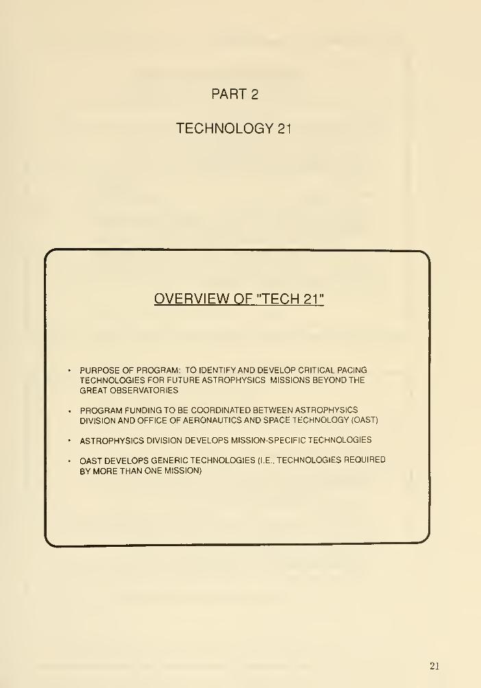
PART 2
TECHNOLOGY 21
OVERVIEW OF "TECH 21"
PURPOSE OF PROGRAM: TO IDENTIFY AND DEVELOP CRITICAL PACINGTECHNOLOGIES FOR FUTURE ASTROPHYSICS MISSIONS BEYOND THEGREAT OBSERVATORIES
PROGRAM FUNDING TO BE COORDINATED BETWEEN ASTROPHYSICSDIVISION AND OFFICE OF AERONAUTICS AND SPACE TECHNOLOGY (OAST)
ASTROPHYSICS DIVISION DEVELOPS MISSION-SPECIFIC TECHNOLOGIES
OAST DEVELOPS GENERIC TECHNOLOGIES (I.E., TECHNOLOGIES REQUIRED
BY MORE THAN ONE MISSION)
21

METHOD OF IDENTIFYINGCRITICAL TECHNOLOGIES
THE "LDR" METHOD HAS BEEN ADOPTED BY THE ASTROPHYSICS DIVISION AS THEBEST WAY TO IDENTIFY CRITICAL TECHNOLOGIES. THIS INVOLVES:
• IDENTIFICATION OF ONE OR MORE "STRAWMAN" MISSIONS WHICH ARE TYPICAL OF(BUT NOT NECESSARY IDENTICAL TO) THE PLANNED MISSIONS
• NASA CENTER SELECTED AS "LEAD" FOR EACH STRAWMAN MISSION
• SERIES OF 2-3 WORKSHOPS/MISSIONS, AT = 1 YEAR INTERVALS, TO DEFINE
MISSION SCIENCE OBJECTIVES. METHOD OF IMPLEMENTATION, PACING
TECHNOLOGIES, AND TO IDENTIFY SCIENCE/TECHNOLOGY TRADES
. MEETINGS CO-SPONSORED AND ATTENDED BY BOTH OAST AND OSSA
. FOLLOW- ON TECHNOLOGY STUDIES COORDINATED BETWEEN OFFICES, WITH
RESULTS FEEDING INTO NEXT WORKSHOP
TECHNOLOGY 21 PROGRAM STATUS
WORKSHOP SERIES COMPLETED FOR LDR
WORKSHOPS CURRENTLY UNDERWAY FOR INTERFEROMETRY GRAVITY
PHYSICS. AND 10 METER TELESCOPE
ADDITIONAL WORKSHOP SERIES CONTEMPLATED
TECHNOLOGY 21 PROGRAM ELEMENTS SELECTED BY "POPULAR DEMAND-
SIGNIFICANT FUNDING STARTS FY 92 AND RAMPS UP RAPIDLY
LUNAR PROGRAM MAY RESULT IN AUGMENTATION (TO BE USED FOR LUNAR
PROGRAM CANDIDATES)
22

PART 3
LUNAR PLAN
EARLY LUNAR-BASED SKY SURVEY:THE CRATER TELESCOPE
DESCRIPTION:
• EXTREMELY WIDE BAND, VERY DEEP, UV/OPTICAL IMAGING SURVEY
• SURVEY ADJACENT STRIPS (OR SAME STRIP) OF SKY AT 1 MONTH INTERVALS
• A WIDE-FIELD ZENITH-POINTED TELESCOPE OF =2 M APERTURE
• FOCAL PLANE READ OUT AT APPARENT SIDERAL RATE
• SEVERAL DETECTORS IN FOCAL PLANE. SENSITIVITY: 0.1 TO 10 MICRONS
SCIENTIFIC RATIONALE:
• SIMULTANEOUS UV/VIS/IR "PALOMAR SKY SURVEY"
• 100 TIMES MORE SENSITIVITY (V>25) AND 20 TIMES MORE RESOLUTION (=0.1 ARCSECONDS AT 0.5 n) THAN PALOMAR SURVEY
• 1000 SQUARE DEGREE FIELD OF VIEW. SAMPLED ANNUALLY
SPECIAL ADVANTAGES OF LUNAR SITING:
• LONG INTEGRATION TIME (HIGH SENSITIVITY) AFFORDED BY LUNAR ORBIT
• NO POINTING REQUIRED
. TELESCOPE CAN BE PASSIVELY COOLED TO CRYOGENIC TEMPERATURES FOR
OPERATION OF THE DETECTORS
• TELESCOPE CAN BE SHIELDED NATURALLY WITH CRATER OR EXCAVATION FOR
PROTECTION FROM HIGH COSMIC RAY EVENT RATE
pRnr.RAMMATIC RATIONALE:
• UNIQUE CAPABILITY TO SURVEY LARGE AREA OVER WIDE BANDPASS
. WILL SUPPORT OTHER LUNAR-BASED ASTRONOMY FACILITIES
• TECHNOLOGY WELL DEVELOPED
• LOW COST EASY TO INSTALL AND OPERATE
23
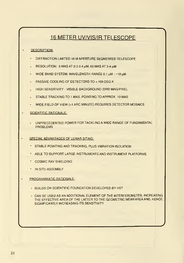
16 METER UV/VIS/IR TELESCOPE
DESCRIPTION:
DIFFRACTION-LIMITED 16 M APERTURE SEGMENTED TELESCOPE
RESOLUTION: 6 MAS AT 0.3-0.4 nM, 60 MAS AT 3-4 ^M
WIDE BAND SYSTEM, WAVELENGTH RANGE 0.1 ^M - -10 nM
PASSIVE COOLING OF DETECTORS TO < 100 DEG K
HIGH SENSITIVITY - VISIBLE BACKGROUND 33RD MAG/PIXEL
STABLE TRACKING TO 1 MAS. POINTING TO APPROX. 10 MAS
WIDE FIELD OF VIEW {>1 ARC MINUTE) REQUIRES DETECTOR MOSAICS
SCIENTIFIC RATIONALE:
UNPRECEDENTED POWER FOR TACKLING A WIDE RANGE OF FUNDAMENTALPROBLEMS
SPECIAL ADVANTAGES OF LUNAR SITING:
• STABLE POINTING AND TRACKING, PLUS VIBRATION ISOLATION
• ABLE TO SUPPORT LARGE INSTRUMENTS AND INSTRUMENT PLATFORMS
• COSMIC RAY SHIELDING
• IN-SITU ASSEMBLY
PROGRAMMATIC RATIONALE:
• BUILDS ON SCIENTIFIC FOUNDATION DEVELOPED BY HST
• CAN BE USED AS AN ADDITIONAL ELEMENT OF THE INTERFEROMETER, INCREASING
THE EFFECTIVE AREA OF THE LATTER TO THE GEOMETRIC MEAN AREA AND, HENCE,
SIGNIFICANTLY INCREASING ITS SENSITIVITY
24

LUNAR-BASED SYNTHETIC APERTUREINTERFEROMETER
DESCRIPTION:
• OPTICAL EQUIVALENT TO RADIO VLBI
• 10 KM BASELINE INTERFEROMETER WITH MULTIPLE 1 - 3M APERTURES
10 MICRO ARC SECOND IMAGING, 10-100 NANO ARC SECOND ASTROMETRY
• EVOLUTIONARY DESIGN (START WITH 2 ELEMENTS, END WITH 20-30)
• TOTAL EVENTUAL COLLECTING AREA 50 - 1 00 SQUARE METERS
30 MAG/PIXEL POINT SOURCE SENSITIVITY
SCIENTIFIC RATIONALE:
• RESOLVE BROAD LINE REGION AND NARROW LINE REGION IN AGN's
• ISOTROPY AND UNIFORMITY OF HUBBLE FLOW TO 1%, PARALLAX OF OBJECTS TO 10s
OF MEGAPARSECS
• IMAGE WHITE DWARFS TO 10 X 10 PIXEL
• IMAGE ACCRETION DISKS AROUND STELLAR OBJECTS. NEUTRON STARS, BLACK HOLES
• DETECT AND CHARACTERIZE PLANETS
SPECIAL ADVANTAGES OF LUNAR SITING:
• ULTRA-ACCURATE BASELINE DETERMINATION ON AN ATMOSPHERE - FREE BODY
• LOW NIGHTTIME TEMPERATURE (PASSIVE COOLING OF OPTICS)
PROGRAMMATIC RATIONALE :
• EARLY SCI/TECH DEMONSTRATION POSSIBLE WITH SHORTER BASELINE (<1 OOM)
ORBITING INTERFEROMETER
• EVOLUTIONARY GROWTH OF LUNAR-BASED INTERFEROMETER
• A 16 METER TELESCOPE CAN BE A POWERFUL INTERFEROMETER ELEMENT
25

DISCUSSION
niingwotth: Can you comment on how the science goals in NASA's response to the President's July
20 initiative will be iterated with the science community following the submission of the report to the
NSC.
Pilcher : NASA's 90 day study (in response to the President's July 20 initiative) must be broad, but
its scope and brevity limits its depth. The process of defining the science content of human exploration
missions must be a continuing one. Mike Duke has been detailed to the OSSA front office to work
with all the science Divisions and the external communities on defining science for the 90 day report.
That process must continue beyond the 90 day study to provide scientific input of increasing maturity
to the Office of Exploration mission studies.
Weiler : We have agreed within Astrophysics that we will iterate and that we will use the advisory
structure (the MOWG's), but we will also get help from the Astronomy and Astrophysics Survey
Committee - from a broader community.
Breckiiuidge: Is the "crater" telescope considered to be a "suitcase" telescope mission to the moon?
A 1 meter telescope is more like a large steamer trunk than a "suitcase."
Weiler : Yes, "suitcase" means requiring little or no assembly from the astronaut. Deployment and
pointing (rough) are acceptable. Larger than a suitcase is ok.
26

ESA Long Term Plans and Status
Duccio Macclietto
European Space Agency
Introduction
The European Space Research Organization, the predecessor of ESA, was estabhshed
some 25 years ago. The main goal then was to coordinate the work of European as-
tronomers and scientists to design and build a telescope to be placed in Earth's orbit. As
it turned out, the first satellite that was built was not an astronomical satellite, it was a
space plasma physics satellite. Since those early days, ESA has conducted a very active,
although budget limited, research program in astronomy. The first astronomical satellite
that was launched was TD-IA, which carried an ultraviolet telescope. It was followed by
COS-B, which conducted an all sky survey of gamma-ray sources. That was followed by
a joint mission with NASA, the International Ultraviolet Explorer satelUte (lUE), well
known to all of you, and then lately the EXOSAT, which explored the X-ray region.
The Horizon 2000 Program
Following these early successful missions, a study was conducted five years ago by
ESA to define with European scientists the long range priorities in space research for
the following decade. There were extensive studies within the European community to
define the mission of interest to each discipline. This was further refined over a two-year
period, and the result of that program is what is now called the European Space Agency's
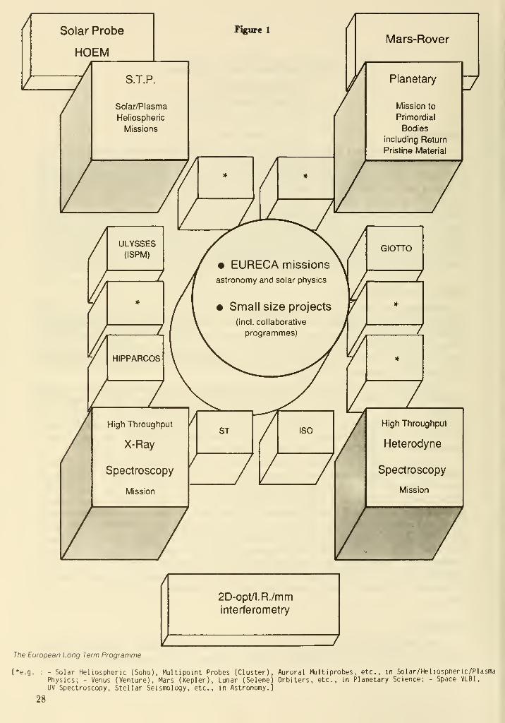
"Horizon 2000", represented in Figure 1.
The program is built around what are called the four "corner stone" missions. These
typically cost upwards of 500 miUion dollars, while ESA's budget for scientific research is
of the order of 300 million dollars per year. What that means is that ESA can build only
one of these satellites at a time. While one mission is winding down a start wiU be madeon the next. The first cornerstone to be built is the SOHO/CLUSTER mission, again a
collaboration with NASA. It will be followed later by the X-ray mission XMM.The smaller boxes in Figure 1 are missions of the 200 million dollar type. Such
missions include satellites such as Hipparcos and the ESA's contribution to the Hubble
Space Telescope. There are also a few empty boxes, and these are opportunities for
future missions which I will briefly describe little later on. The circular central region
in the center represent low-cost missions, on the order of 100 million dollars or less.
These are either throw away type missions, assorted missions, or joint missions with
NASA or other agencies where ESA's contribution would be less than 100 million dollars.
The outer rectangular areas indicate missions which will be ready at a time well beyond
Horizon 2000. In addition, the plan identifies a number of missions that have considerable
scientific interest in the European community but are of a complexity, or cost or require
technological advances of such a magnitude that it is impossible to carry them out in this
century.
ISO/XMMIf we turn to astronomy, the mission that is currently being built is the Infrared Space
Observatory, ISO. It is a 60 centimeter infrared telescope which is surrounded by a large
27
A Solar Probe
HOEM
Figure 1
S.T.P.
Solar/Plasma
Heliospheric
Missions
ULYSSES(ISPM)
HIPPARCOS
High Throughput
X-Ray
Spectroscopy
Mission

Dewar which keeps the temperature of the telescope and the detectors at about 4 degrees
Kelvin. It will carry about 2,000 liters of hehum. The total mass is about 5,000 kilos and
it is expected to be launched in about 1996.
Following ISO, other approved programs, which are not being built yet but are in a
detailed definition phase, are: Cassini, a joint mission with NASA, that will explore the
atmosphere and the surface of Titan which is scheduled for launch in 1996; XMM, which
is a high X-ray spectroscopy mission to be launched in 1998 with the Ariane launcher; and
the Columbus polar platform mission, which is mainly devoted to study solar terrestial
physics.
Of particular relevance to this conference, XMM consists of a series of nested tele-
scopes and a number of spectrometers and imagers. The imaging quality is only about
30 arc seconds, the emphasis being to build a hght bucket to carry out intermediate
resolution spectroscopy.
FIRST
The next cornerstone astronomy mission is the Far Infrared Space Telescope (FIRST).
It is a heterodyne spectroscopy mission. It will cover the wavelength range between a
hundred microns and one milHmeter. This is an important range because of the availability
of both continum radiation, and a number of atomic and molecular lines. The basehne
is to have a passively cooled antenna about 8 meters in diameter, able to carry out high
spatial resolution observations. The FIRST antenna can be either a deployable antenna or
a segmented antenna, and that will depend on what type of technology is the best suited
at the time of launch. The Dewar at the focal plane is of the same type of technology
that has been developed for ISO and will keep the experiments at about 4 degrees Kelvin.
The launcher should be an Ariane 5, and the orbit is a 24 hour type orbit. The pointing
accuracy will be one arc second with a stabihty of about half an arcsecond. The design of
the antenna is a Cassegrain with a prime focal ratio of F/1.35. It will not have a chopping
secondary, because of the great added complexity that this will require. The material of
the antenna will be carbon fiber and it will have a very high surface accuracy of about
6 microns. It will have an error of about 100 microns, and a random error of about 20
microns. The model payload detectors includes heterodyne spectroscopy with SIS mixers,
spectrophotometry with a grating combination, a far infrared spectrometer to observe
the wavelength range between 100 and 250 microns, and a far infrared photometer. TheFIRST mission is currently planned for year 2010.
Interferometry
ESA has estabhshed a space interferometry study team to discuss aperture synthesis
in space. The terms of reference of that team were to define the main science goals, to
establish a strategy for ESA involvement in the project, to identify and discuss differ-
ent mission concepts, to identify science trade-offs and advise on the technical research
program that is needed to carry out this long-term program. This team met a numberof times and they have recently issued a report. They compare a number of different
concepts from rigid structures with a number of free flying elements to floppy structures
of the VLA type. The final two concepts that have emerged are Oasis and Float. Oasis
has a large coherent field of view, while Float is a fiber-linked optical array. The problem
29
here is of course to develop fiber-optics which have good transmission in the ultraviolet.
Tlie two studies, one was a Michelson-type arrangement, and the other is a Fizeau-type
arrangement for beam recombination. In one case, the structure is floppy, in the Fizeau
case is semi-rigid with active optics. The array shape in the case of Michelson would be
a VLA type - a wide type array, with non-redundant spacing and Fizeau again would be
a non-redundant space ring with about 12 different telescopes. In one case the structure
is a space inflatable structure with optical elements connected through rigid tubes, the
other an inflatable structure. These two types of structures are being developed by in-
dustry in Europe for other applications at this time. So there is some hope that it will be
useful for this project. In the Michelson case the ultraviolet is clearly excluded from the
arrangement, whereas in the Fizeau there is a possibility to go down to below 0.1 micron.
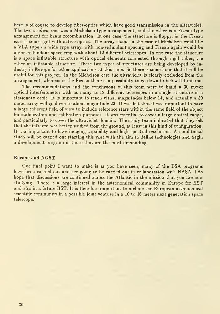
The recommendations and the conclusions of this team were to build a 30 meter
optical interferometer with as many as 12 different telescopes in a single structure in a
stationary orbit. It is important to reach visual magnitudes below 14, and actually a 30
meter array will go down to about magnitude 23. It was felt that it was important to have
a large coherent field of view to include reference stars within the same field of the object
for stabilization and calibration purposes. It was essential to cover a large optical range,
and particularly to cover the ultraviolet domain. The study team indicated that they felt
that the infrared was better studied from the ground, at least in this kind of configuration.
It was important to have imaging capabihty and high spectral resolution. An additional
study will be carried out starting this year with the aim to define technologies and begin
a development program in those that are the most demanding.
Europe and NGST
One final point I want to make is as you have seen, many of the ESA programshave been carried out and are going to be carried out in collaboration with NASA. I do
hope that discussions are continued across the Atlantic in the mission that you are nowstudying. There is a large interest in the astronomical community in Europe for HSTand also in a future HST. It is therefore important to include the European astronomical
scientific community in a possible joint venture in a 10 to 16 meter next generation space
telescope.
30
The Next Generation UV-Visible-IR Space Telescope
Garth lUingworth
University of California Observatories/Lick Observatory
Board of Studies in Astronomy and Astrophysics
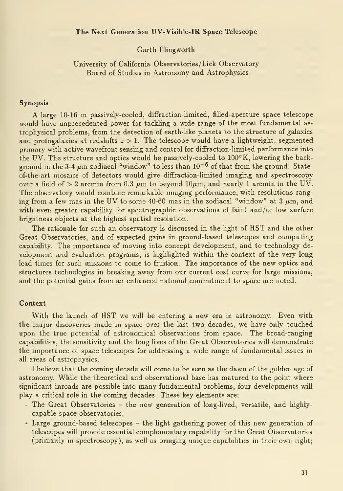
Synopsis
A large 10-16 m passively-cooled, diffraction-limited, filled-aperture space telescope
would have unprecedented power for tackling a wide range of the most fundamental as-
trophysical problems, from the detection of earth-Uke planets to the structure of galaxies
and protogalaxies at redshifts z > 1. The telescope would have a lightweight, segmented
primary with active wavefront sensing and control for diffraction-limited performance into
the UV. The structure and optics would be passively-cooled to 100° K, lowering the back-
ground in the 3-4 fim. zodiacal "window" to less than 10~" of that from the ground. State-
of-the-art mosaics of detectors would give diffraction-limited imaging and spectroscopy
over a field of > 2 arcmin from 0.3 /xm to beyond lO/xm, and nearly 1 arcmin in the UV.The observatory would combine remarkable imaging performance, with resolutions rang-
ing from a few mas in the UV to some 40-60 mas in the zodiacal "window" at 3 /xm, and
with even greater capabihty for spectrographic observations of faint and/or low surface
brightness objects at the highest spatial resolution.
The rationale for such an observatory is discussed in the light of HST and the other
Great Observatories, and of expected gains in ground-based telescopes and computing
capabihty. The importance of moving into concept development, and to technology de-
velopment and evaluation programs, is highhghted within the context of the very long
lead times for such missions to come to fruition. The importance of the new optics and
structures technologies in breaking away from our current cost curve for large missions,
and the potential gains from an enhanced national commitment to space are noted.
Context
With the launch of HST we will be entering a new era in astronomy. Even with
the major discoveries made in space over the last two decades, we have only touched
upon the true potential of astronomical observations from space. The broad-ranging
capabihties, the sensitivity and the long Hves of the Great Observatories will demonstrate
the importance of space telescopes for addressing a wide range of fundamental issues in
all areas of astrophysics.
I believe that the coming decade will come to be seen as the dawn of the golden age of
astronomy. While the theoretical and observational base has matured to the point where
significant inroads are possible into many fundamental problems, four developments will
play a critical role in the coming decades. These key elements are:
- The Great Observatories - the new generation of long-lived, versatile, and highly-
capable space observatories;
- Large ground-based telescopes - the light gathering power of this new generation of
telescopes will provide essential complementary capabihty for the Great Observatories
(primarily in spectroscopy), as well as bringing unique capabihties in their own right;
31
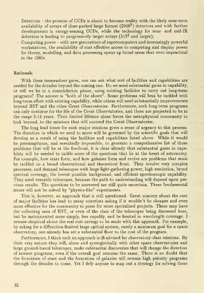
Detectors - the promise of CCDs is about to become reality with the likely near-term
availability of arrays of close-packed large format (2048^) detectors and with further
developments in energy-sensing CCDs, while the technology for near- and mid-IR
detectors is leading to progressively larger arrays (512^ and larger);
Computing power - with new generations of supercomputers and increasingly powerful
workstations, the availability of cost effective access to computing and display power
for theory, modelling, and data processing opens up broad areas that were impractical
in the 1980s.
Rationale
With these tremendous gains, one can ask what sort of faciHties and capabilities are
needed for the decades beyond the coming one. Do we need substantial gains in capability,
or will we be in a consolidation phase, using existing facilities to carry out long-term
programs? The answer is "both of the above". Some problems will best be tackled with
long-term effort with existing capability, while others will need substantially improvements
beyond HST and the other Great Observatories. Furthermore, such long-term programs
can only continue for the life of the Great Observatories, and these are projected to be in
the range 5-15 years. Their hmited hfetime alone forces the astrophysical community to
look beyond, to the missions that will succeed the Great Observatories.
The long lead times for such major missions gives a sense of urgency to this process.
The direction in which we need to move will be governed by the scientific goals that will
develop as a result of using the facihties and capabihties listed above. While it would
be presumptuous, and essentially impossible, to generate a comprehensive list of those
problems that will be at the forefront, it is clear already that substantial gains in capa-
bility will be needed to tackle some of the questions that he at the heart of astronomy.
For example, how stars form, and how galaxies form and evolve are problems that must
be tackled on a broad observational and theoretical front. They involve very complex
processes, and demand telescopes with large light-gathering power, high resolution, broad
spectral coverage, the lowest possible background, and efficient spectroscopic capabihty.
They need versatile telescopes, because the path to understanding wiU depend upon pre-
vious results. The questions to be answered are stiU quite uncertain. These fundamental
issues wiU not be solved by "physics-Hke" experiments.
This is, however, an approach that is stiU questioned. Great concern about the cost
of major facihties has lead to many scientists asking if it wouldn't be cheaper and even
more effective for the community to press for more specialized projects. These may have
the collecting area of HST, or even of the class of the telescopes being discussed here,
but be instrumented more simply, less capably, and be hmited in wavelength coverage. I
remain skeptical about the real cost savings to be made with this approach. For example,
by asking for a diffraction-hmited large optical system, surely a minimum goal for a space
observatory, one already has set a substantial floor to the cost of the program.
Furthermore, I think such an approach is ill-advised for observatory-class missions. Bytheir very nature they will, alone and synergisticaUy with other space observatories and
large ground-based telescopes, make substantial discoveries that will change the direction
of science programs, even if the overall goal remains the same. There is no doubt that
the formation of stars and the formation of galaxies will remain high priority programs
through the decades to come. Yet I defy anyone to map out a strategy for solving these
32

problems that they are confident will survive the coming decade or two of observations.
These problems are not amenable to defining an "experiment" that will lead to their
solution. Broad ranging capabiUty is needed that will allow us to build upon a growing
base of understanding - to branch out to follow the leads shown by observations.
Interestingly, I think that we have a consensus by example within the astrophysical
community that is consistent with this view. There are large numbers of universities
around the country that are planning telescopes with their hard-won private money. Al-
most invariably, when the funds allow, they choose large versatile telescopes, and are the
envy of their colleagues for so doing. Astronomers are "voting with their feet" for large,
versatile telescopes.
I think that this view will be strengthened as the community experiences the Great
Observatories and the new 8-10+ m large ground-based telescopes.
This is not to say that such telescopes are all that are needed. Problems such as
surveys in wavebands inaccessible from the ground, the structure on the smallest scales in
AGNs and quasars, defining the fundamental distance and reference systems, high energy
events, etc. are going to require astrometric systems, interferometers, survey telescopes,
specialized x-ray and 7-ray telescopes and so on. COBE is a current example of a very
impressive and valuable experiment. These facilities provide an essential complementary
element to the large versatile telescopes. The large telescopes can be thought of as pro-
viding the heart of an organic program which is supported by a wide variety of more
directed, more focused capabilities.
Over the next 15 years or so of HST's lifetime, it is clear that the astrophysical
community will become "addicted" to HST's capabihties - namely, its:
- resolving power,
- UV coverage,
- near-IR capability,
- and the predictabiHty of its performance.
It will not only have a major impact on what we do, but also on how we do it.
Yet, for all the wonderful new capabihties offered by HST, it is clear that there will
be a component of great frustration. It is simply too small to do spectroscopy at the
level demanded by many of the outstanding problems, and almost certainly too small
for foUowup of many of its discoveries with its powerful imaging systems. The new,
large ground-based telescopes wiU be able to provide the necessary spectroscopic foUowup
in many cases, but their poor imaging capabihties by comparison with those on HST,their lack of UV coverage, and their high IR background will be a Hmiting factor, and a
substantial one.
Next Generation Space Telescope
While these general considerations provide a broad rationale for a next generation
large UV-Visible-IR telescope, it is the scientific case itself which leads one to great
enthusiasm for such an observatory. As can be seen in the subsequent science papers,
a particularly compelling scientific case can be made for a 10-16 m class space telecope
with the proposed performance capabilities noted in the introduction to the Workshop.
Words such as "awesome" and "astonishing" have been used by more than one scientist
upon thinking about or being shown the capabilities of such a telescope.
33

The goal is for a 16 m class passively-cooled, diffraction-limited, wide-band telescope.
Its instrument complement would be sensitive from the UV at ~ 0.1 /xm to beyond 10
fim. With passive cooling of the structure and optics to less than 100°K, the background
would be lowered in the 3-4 fim zodiacal "window" and at longer wavelengths to less than10~^ of that from the ground. The diffraction-limited images would be 7 milliarcsec at 0.5
fim. It could reach 32 mag in the visible at 10:1 S/N in less than 10^ s. State-of-the-art
mosaics of detectors would give diffraction-limited imaging and spectroscopy over a field
of > 2 arcmin from 0.3 fim to beyond lO/xm, and to nearly an arcmin in the UV.
The combination of high resolution, low background, wide bandwidth, and wide field
are what give this telescope its unique capabilities. For example, the low background
across the wavelength region covered by this telescope, ~0.1 - 20 ^m, allows for measure-
ments to be made of much, if not most, of the baryonic matter in the universe, assuming
the dark matter to be non-baryonic. Furthermore, the resolution provides an excellent
match to some natural length scales in the universe. For example, the telescope is partic-
ularly well-matched to direct observations of the structure in galaxies and proto-galaxies
at high redshift. Structures in galaxies (e.g., star forming regions, spiral arms, disk/bulge
length scales, merger "arms and tails") have characteristic scales of 100 pc - 1 kpc. With10 mas resolution we can resolve structures in galaxies at any redshift with the resolution
that we now study the nearest cluster of galaxies, the Virgo cluster, from the ground.
This is an astonishing capability and is shown very explicitly in the paper by Jim Gunnwhere he simulates images at a redshift z = 1 of a spiral galaxy with HST and with a 15
m telescope.
The question of the detection of earth-like planets in stellar systems within 10 pc of
the sun and the subsequent spectroscopic observations of those planets with the goal of
detecting ozone and other molecules indicative of life is addressed by Roger Angel in this
volume. It is an extremely challenging observational program, and one which requires a
16 m telescope with all the capabilities summarised here. Yet it is an immensely exciting
goal and one which captures the imagination not only of astronomers and life scientists
but of people at large.
Times cales
HST has a nominal life of 15 years. It is now approaching 20 years since the start
of Phase B for HST. It is clear that the pre-Phase A conceptual and technology develop-
ment needs to start very soon to minimize the gap between HST and its successor. Thematurity of astronomy, and the resultant difficulty and complexity of the scientific issues
that are now at the forefront of the field, requires long-term observational capability. Asubstantial gap, greater than 5 years, for example, would have a very deleterious effort on
the productivity in the field and would be a waste of the scientific talent and resources
that will build up around HST and the Great Observatories.
An added concern, of course, is the tough environment in which spacecraft operate,
especially low earth orbit spacecraft with the attendent thermal cycling. If HST, an
immensely complex instrument, degrades faster than expected in a way which cannot
be accommodated by the M&R (Maintenance and Refurbishment) program, we could
potentially be facing a large gap before the next mission. This would also impact the
productivity of AXAF and SIRTF, because the multiwaveband synergy would be lost,
undercutting one of the pillars of the Great Observatory program. A gap in capability in
34
the central UV-Visible-IR wavelength region of 10 years would be far too long. The goal
should be for a gap of less than 5 years between HST and its successor.
Cost
One scaling "law" that has been used in the past for telescopes has cost rising as
the 2.7 power of the diameter, i.e., (£>i/Z>2)'^-^. Applying such a factor for a 10-16 mclass telescope based on HST's cost leaves one gasping. However, such an approach is
inappropriate given changes in technology and the gains that can be accomplished byexperience and attention to detail. Recent ground-based large telescopes have brokenthe cost-curve for 1950-70's telescopes by a factor of four, and further gains are in the
pipeline. The German science community is seriously looking at a structure, the Hexapodstructure like that shown in Figure 2 in the Introduction, that is based on experience with
flight simulators. This offers large weight savings, and hence cost savings, even beyondthe space frame designs currently being used for the Keck Telescope. For a 12 m diameter
telescope, they project total weights comparable to previous-generation 4 m telescopes.
Another area where major gains in performance with attendent weight savings, andhence cost savings, can be made is in the area of lightweight optics. As we can see fromthe discussions at this meeting, this is an area where major improvements in fabrication
and polishing technology are occuring. The combination of improved performance andlower weight for the optical segments will directly and dramatically affect the final cost
of the NGST.We are clearly very early on the learning curve for observatory-class missions, and
should have every expectation for substantial gains in lowering the cost of such missions.
HST can be an extremely valuable experience base for such gains. I hope that as wepass launch, as HST becomes a powerful, productive observatory, that we can revisit the
construction of HST in a very objective, non-accusatory way with the goal of improving
our ability to do such missions faster and cheaper. The computer industry and the
Japanese automobile industry have made remarkable strides by learning from experience,
by attention to details, and by maximizing the product per dollar. There is no reason
why we cannot do the same.
Turning to the revenue side of the equation, I think that we are ripe for a renewedand expanded committment to space, and to space science. With the remarkable political
changes that are taking place in the world, I see a renewed emphasis on space as the focus
of our high-technology effort. Even modest real (after inflation) annual increases can very
substantially increase the total budget over a multi-year period. For example, just bymatching the GNP growth, say 3% per year, plus adding another 5% above inflation,
for a period of fifteen years through to 2005, the annual budget for space activities as
carried out through NASA could grow from $13 billion to $41 billion in 1990 dollars. Thespace science program that could be carried out with the usual fraction of such a budget,
combined with the increased capabilities that could be obtained per dollar through the
technology and potential fabrication improvements noted above, is exciting, to say the
least.
The goal of building a 16 m class telescope early in the next century is an ambitious
one, but one that is closer at hand and more realistic than one might initially expect.
This sentiment was echoed in a a study of the long-term goals for space science that wasperformed under the auspices of the National Academies of Science and of Engineering,
35

and of the Institute of Medicine. The study group was tasked with developing a program
for Space Science in the 21st century. The reports of the study groups and an overview
volume have recently been published (1988) under the title Space Science in the Twenty-
First Century: Imperatives for the Decades 1995 to 2015.
The report contains a recommendation for an 8-16 m, passively-cooled, UV-Visible-
IR telescope. The report's concluding remark (from the section discussing an 8-16 mtelescope in space) notes that: Given a well-directed technology development program,, the
task group anticipates that an 8 to 16 m telescope will prove to be within closer reach than
a simple extrapolation from, HST would suggest.
While this report recognizes the scientific value of such a telescope, and I think re-
alistically appraises the situation vis-a-vis the needed technology developments, it is but
a start to a wide-ranging program leading to the development of a 16 m class telescope
within a broad space science program. This workshop takes the next critical step.
36

Session 2
Scientific Potential


NGST and Distant Galaxies
James GunnPrinceton University
One of the most-heralded abilities which HST will bring us is the capability to study
the morphologies of quite distant galaxies, distant enough that the look-back time is a
substantial fraction of the age of the universe. It appears that with substantial expenditure
of observing resources, crude morphological information can be obtained out to redshifts
approaching unity, with quite good images at, say, z=0.5.
Most theories of galaxy formation, and indeed the growing body of ground-based
spectroscopic evidence, put the epoch of galaxy formation earlier, though I think the
weight of modern evidence is that it is not much earHer, and the redshift range 2-3
promises to be of enormous interest. HST, by reason of its small collecting area and,
to some extent, hmited resolution, cannot address this problem directly. The awesome
capability of a fifteen-meter diffraction-limited telescope in high orbit, however, would
allow us to see what is going on at these epochs directly and with considerable ease-if
stiU requiring a great deal of observing time.
It is perhaps worth a few words to say why one expects to see something interesting,
and to discuss what one might see. On the theoretical front, the popular Cold Dark
Matter scenario requires that galaxy formation be late, and furthermore in general quite
chaotic. The model of Baron and White and the newer models of Katz(1989), the latter
incorporating real hydrodynamics and an attempt at a physically reasonable star for-
mation description, produce objects which at the present epoch look very much Uke the
galaxies we see (the former an ellipical galaxy, the latter both ellipticals and convincing
disk spirals). The gross morphology of these systems changes little past z=l, but between
z=2 and z=3 the objects look very different from galaxies today, and in fact in most
surveys, if they could be seen, would be counted as multiple objects, there being several
more-or-less isolated islands of star formation in merging, still mostly gaseous, blobs. If
one takes the predicted brightnesses of these objects seriously (which one does, of course,
at one's peril- the star formation rates are are, well, very uncertain), they should be visible
in the very deep ground-based surveys of Tyson and others, and if so, could well explain
the mystery of the counts of galaxies. The counts are several times too high fainter than
about 25th magnitude to be explained by conventional models, and extreme evolutionary
models which do fit them fail spectacularly to fit the observed redshift distributions at
brighter levels. If, in fact, one were observing not galaxies at very faint levels, but pieces
of galaxies putting themselves together to make galaxies, the problems with the counts
would be much less severe. It is interesting (but again, regard with caution) that the
visual brightness of these objects is predicted to change little between z=2 and z=l, the
integrated brightness corresponding to about V=23-24 for the progenitor of a big (Mv =-21) spiral at the present epoch. But that brightness is not lumped in a single concentra-
tion until about z=1.5, and prior to that is quite complex, with several separated regions
of star formation contributing comparably to the total luminosity.
39

What manner of instrumentation would it require to investigate this birth process?
First of all, the lumps in which stars first form are very small, so one needs high resolution,
ideally about 100 pc at z=l-2, or about 15 milliarcseconds. Secondly, one needs high
sensitivity; in the 'turn-on' phase when the object is quite chaotic, the total brightness
may correspond to V=26 but might consist of several lumps spread over a few arcseconds.
It becomes clear on a little reflection that a space-based telescope several times the
aperture of HST is needed, and furthermore that such an instrument would do very nicely
indeed. I will end this discussion by presenting some simple simulations of observations
done with an instrument with the following properties:
- 16-meter aperture
- f/20 modified Ritchey optical system; the scale is 1.45 microns/mas
- 5 arcmin diffraction-limited field; this can be easily achieved with a single-element
refractive astigmatism corrector
- FWHM = 10 mas or about 15 microns at V- Camera with 3 reflections and 1 transmissive element (astig. corr.)
- 8192x8192 CCD with 7.5 micron pixels; the focal plane might be paved with 25 of
these devices; each has a field 40" square
- Read noise of 2.5 electrons RMS for the CCD.- For the near IR, a 1024x1024 HgCdTe device with 40 micron pixels would give a field
of 30 arcseconds with 25 mas pixels; it seems likely that a read noise of 10 electrons
will be attainable.
A comment about the assumed technology is perhaps in order...the tallest order in
the list is almost certainly the diffraction-limited 15-meter primary, which others in this
conference wiU address with much more expertise than I possess. The optical layout is
strjiightforward, and the detector properties probably a much-too-conservative extrapo-
lation of the current art. I have assumed a high-earth-orbit environment, which is opera-
tionally very much simpler than the low-orbit environment of HST. It will allow passive
cooling of the optical detectors (though the IR imagers and other IR instrumentation
which will doubtless be aboard wiU certainly require cryogens or other active cooling.)
The radiation environment is relatively benign. With moderate shielding, such as is
used in the Galileo detectors, the proton rates are of order 3 per square centimeter per
second and the electron rates much lower. The proton flux can rise by four orders of
magnitude during a very energetic solar flare event, but the dose and duty cycle of such
events is very much lower than the South Atlantic anomaly which one has to deal with in
low orbit. The typical rates are higher than the WF/PC rates, for instance, but not by
much. With the 7.5 micron pixels assumed for the opticail sensors, the mean time for a
given pixel to be hit is about 6 x 10^ seconds, while the detected sky photon rate is of the
order of .015/second in the visible and near IR with broad-band filters. Thus exposures of
the order of 1000 seconds will have sky levels of order 15 electrons and will be well into the
shot-noise limited regime while of order 1 pixel in 600 will have suffered a cosmic-ray hit;
it seems straightforward that a three-exposure sequence might be standard, with a simple
voting scheme to eliminate hits. The situation in the IR is much trickier; the assumed
40-micron pixels are 28 times larger than the assumed optical ones, the read noise worse,
and the background fluxes lower. Dividing the exposure into roughly 200-500 second
segments will still put one close to the shot-noise limit and have only one or two percent
of the pixels hit during any one sub-exposure, but one would be much more comfortable
40
with a lower noise floor (which may well be possible by the time this instrument is built.)
The capabilities of such an instrument are awesome for a very large range of problems.
For example, if one imagines a set of broad (20%) filters spanning the range 2900 AA to 2.2
microns, a 2-hour exposure would yield 10:1 signal-to-noise photometry at the following
visual magnitudes:
Wavelength: 2900A 4300A 6200A 9300A 2.2/i
Magnitude: 30.5 32.5 32.5 31.0 32.0
for an object with an energy distribution like an FO star. The sun coxdd be detected
with 10:1 S/N at 3.5 Mpc, and a lO-day Cepheid at 200 Mpc. A z=2, Mv=-21.5 normal
gcdaxy containing an 18th magnitude QSO could be detected at 5:1 S/N. (AU the above
for 2-hour exposures).
The simulations I have done are for the nearby galaxy NGC2903, an ScI-II spiral at
about 10 Mpc distance moved to z=l with the assumption of no luminosity evolution.
The image from which the simidations were made was obtained with the 4-shooter CCDcamera on the Hale telescope in 0.8 arcsecond FWHM seeing with a Thuan-Gunn gfUter; the S/N in the image is high enough that noise must be added to it to make the
simulations. Recall that forming galaxies at z=2-3 are expected to have fluxes in the
visible not too different from this, since they will have much more active star formation.
They are all simulations of pictures taken in the 9300-Angstrom 20 per cent filter used
in the above sensitivity calculations; the protogalaxy images will be better at somewhat
shorter wavlengths because of the young stellar populations, though if there are normal
galaxies at z=l the assumed band is probably optimal (we would be better off at 2.2
microns from the point of view of S/N, but the assumed sampling is not as good there.)
The first pictures are simulations of Keck telescope images of this galaxy, with expo-
sures of 3 hours and 30 hours, with a CCD with 0.1 arcsecond pixels and 0.5 arcsecond
FWHM seeing. Although the signcil-to-noise in the long exposure is exquisite, the resolu-
tion is inadequate for any serious morphological study, and realizable g£uns in resolution
by processing will be insufficient to change the situation significantly.
The situation is better, as might be expected, with HST. We show simulated images
with superpositions of WFC images from three and thirty (!) orbits; the thirty-orbit
picture begins to show some detail, and quantities like color gradients can be extracted
with some accuracy, but the (undersampled) resolution of a little less than a kiloparsec is
inadequate to make a clear picture of what is going on in the arms, and one would expect
that a more chaotic, just forming galaxy, while just as bright, would present an even more
confused picture at this level of image quality.
Finally, the 16-meter images for exposure times of 2 hr and 24 hr are shown; while
24 hours may seem excessive, remember that the focal plane of the telescope can cover
25 of the assumed detectors which wiU cover an entire protocluster with one pointing,
so in principle seversd hundred galaxies like this one can be studied with one such long
exposure. The resolution and S/N in the long exposure is similar to the ground-based
picture of 2903 10 Mpc distant, and, in fact, had the seeing been significantly worse in the
2903 image, we would not have been able to simulate the 16-meter image of the galaxy
at z=l at all realistically!
41
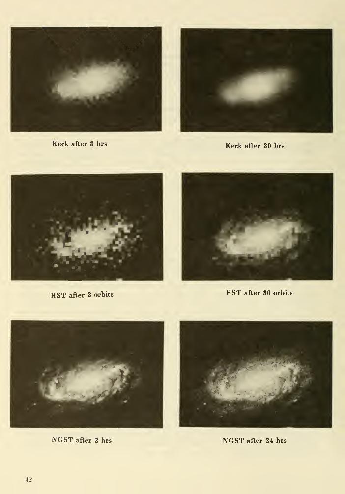
Keck after 3 hrs Keck after 30 hrs
HST after 3 orbits HST after 30 orbits
NGST after 2 hrs NGST after 24 hrs
42

Similar spectacular gains are to be had with spectroscopy. It is easily possible to dodynamics on this galaxy at z=l with a spectrograph optimized for this sort of problem,which is an instrument much more like low-resolution spectrographs on large ground-basedtelescopes than the instruments typically used in space; one would hope that the dynamicsof distant galaxies is an important enough problem that such an instrument might be partof its focaJ-plane complement. A spectrograph with a 0.1 arcsecond-wide slit critically
sampled onto a CCD of the same sort as the imagers (i.e, with an f/2 camera) would havea resolving power of 2000. A 24-hour exposure would result in an exposure level in the skyof about 3500 counts per pixel, with the galaxy at 10 kpc radius contributing a signal of
300 counts. If one binned 4 pixels along the slit for an effective spatial resolution of 2 kpc,
the resulting S/N per resolution element is 12:1; farther in, at 2.5 kpc radius, the S/N in
a single pixel row is 25:1 per resolution element, either sufficient to measure velocities to
a few tens of km/sec at this resolution (and, of course, to explore the stellar populationand HII region chemistry in some detail.). The galaxy uses some 40 pixels (4 arcseconds)
along the slit, so if, for instance, the spectrograph were fed by fiber ribbons, one could
look at of order 50 galaxies at once if the field of the spectrograph could be made big
enough, or using a fiber hydra, one could completely map a 4-arcsecond square region,
essentially the whole galaay. The latter possibility I find quite incredibly exciting; the
dynamics of protogalaxies is certain to be complex, and 2-dimensioncd spectral mappingat relatively high spectral resolution would be a wonderful tool to study them, as weU as
a vast other suite of problems in astrophysics.
DISCUSSION
Gallagher: How bad will the cosmic ray environment be in HEO?
Gnnn : The cosmic ray environment is a problem for HST because of the high readout noise of the
detectors - with the much lower noise expected for future detectors, repeated exposures can be made
and cosmic rays identified and rejected.
Bahcall : I am surprised at the conservatism of these discussions regarding detectors and the field of
view. In 20 years will we not do much better than a factor of 2?
Gnnn : We are looking at mosaics with a large number of pixels to cover the 5 arcmin field so it is a
large gain.
Jackson : Can we support the data rates form these very large pixel sizes?
Gnnn : Computer power increases so switfly that I do not see this being an issue in the future.
43

Planetary Astronomy with a Large Space Telescope
Robert A. BrownSpace Telescope Science Institute
My topic is not well described in terms of objects; it is better viewed as a cluster of activities.
The first is exploration. Voyager 2's recent fly-by of Neptune exemplifies the robotic thrust
of the first thirty years of solar system exploration, which will culminate in human expansion into
space. The second is planetary science, which is the investigation of the underlying processes that
govern the planets or that brought them to their current state. The third is planetary astronomy,
which is the gathering and analysis of light with planetary interest. Astronomy is one of several
research pathways for advancing both solar system exploration and planetary science.
I am personally convinced that a 10-meter—or larger—telescope on the Moon or in Earth orbit
would make nujor new contributions to both the exploratory and the scientific objectives related to
planets and planetary systems. Nevertheless, we learned during the development of the Hubble
Space Telescope (HST) that the potential contributions of a new system will remain just that
—
potential—unless the investments are made to address the complexity of forefront planetary re-
search. In this talk, I have selected some exciting projects in planetary astronomy, but my list is by
no means exhausive. My purpose, simply, is to demon-strate both the latent scientific power and the associ-
ated special requirements of planetary studies
using a large space telescope.
Solar System Inventory. The variety
between and the relationships among the small
bodies of the solar system is an arterial themein planetary science. The study of these
objects is a great research bridge betweeninterstellar material and the meteorites. Alarge space telescope could extend signifi-
cantly the inventory of small objects in the
solar system.
Assuming detections are limited by back-
ground light, an aperture four times larger than
HST would improve the faintest object that could
be studied by a factor of 16 or 3 stellar magnitudes.
This gain would allow us to investigate the asteroid distribution to four-times smaller size or two-
times greater distance. Also, it could uncover entirely new classes of objects in the outer solar
system.
An exhaustive search for faint solar system objects would require immediate access to all deep
images taken with a large space telescope. Images of galactic and extra-galactic fields are, in effect,
double exposures: the universe is seen through the solar system, which can introduce unexpected
and interesting foreground images. Only if those objects are rapidly identified and recovered by
follow-up observations, can the orbits are determined. Only then are the objects "known to sci-
ence." To accomplish this, and so to derive maximum scientific benefit from the deep-space im-
ages, the proprietary data rights must be structured so as to permit dual access to their double
information content.
Jupiter Atmosphere. Groundbased images of Jupiter at 5 micrometers wavelength indicate
that openings exist in the Jupiter clouds through which telescopes can probe to warmer depths in
the atmosphere. A correlation has been found between regions of higher brightness temperature
and certain features seen at higher resolution in visible hght. A diffraction limited 10-meter tele-
scope could exploit this effect to study the vertical structure and distribution of minor constituents
Solar System Exploration
AAAPlanetary p j PlanetaryScience l / Astronomy
44

in the deep atmosphere by looking through the clouds. These observations—combining visible
imagery and infrared spectroscopy—would benefit greatly from the small infrared diffraction-
limited footprint, w^hich v^^ould be about 400 kilometers at 4 AU distance.
Spectrometers with higher resolving power would be needed to perform critical studies of
planetary atmospheres using a large space telescope. In the infrared, where the molecular con-
stituents are spectroscopicaUy active, the resolving power should be greater than about 10,000—
a
value somewhat higher than that discussed by Garth niingworth in his introduction to this work-
shop. In general, planetary studies require optimized instrumentation to derive fuU value from
advances in the basic telescope itself.
Comet Nuclei. We believe that comets consist of interstellar grains and condensed gases
conglomerated in the protosolar nebula. While the comet nucleus is thus an archaeological record,
the coma and tail are not, because the gasses released from the nucleus are quickly modified bychemical reactions. Therefore, gathering the information locked in the nucleus requires address-
ing it or its immediate environment directly.
The acuity of large space telescope would allow studies of freshly produced parent molecules
near a comet nucleus. For a 10-meter aperture, for example, one Nyquist-sampling resolution
element at 0.6 micrometers would correspond to the apparent size of a typical 10 kilometer nucleus
at a distance of 1 AU, and many comets come much closer to the Earth. Imagery obtained at this
spatial resolution could discover how the morphology and rotational characteristics of the nucleus
are related to its activity. One could, for example, place a spectrograph slit at various distances
from the nucleus, measure parent molecules, and document their evolution in distance, which, in
free flight, is time.
A critical requirement for observing comet nuclei—one shared by most planetary studies—is
accurate target acquisition and tracking. The apparent motion of the target is complex, because it
is a superposition of three components. One component is due to heliocentric orbiting, another is
parallax caused by the telescope orbiting the Earth, and a third is possible planetocentric motions
of the target—rotation or satellite orbiting, for example. The capabilities, first, to put the footprint
of the telescope down on a definite place on the changing field, and, second, to hold it there, are
prerequisites to interpreting the observational data v^th confidence. HST has taught us how de-
tailed and challenging are the special pointing requirements for moving targets.
Mars Habitability. The President has declared human exploration of Mars to be a national
objective, and that will require a deeper understanding of the geology, climate, and weather of
Mars. One can envision major research programs on each of those topics.
A 10-meter space telescope would have approximately 6 kilometer resolution on the face of
Mars at visible wavelengths. Using that, one could, for example, map geological units at a higher
detail than has been possible to now. This would establish a basis to extend horizontally whatrobotic missions leam from in situ samples. Another application would be studies of martian dust
storms, which regularly veil the entire planet. They originate in very small regions and becomeglobal in a matter of days. How do dust storms arise and grow? Can we understand them weUenough to be confident about human habitation of Mars? A large space telescope could study
Mars dust storms in an early growth phase with about 6 kilometer resolution—a powerful im-
provement in documenting their evolution.
Dust storm studies would require very rapid rescheduling performance by the operational
system for a large telescope. The onset of a dust storm could be learned from groundbased obser-
vations. In a matter of hours, the large space telescope would need to acquire the planet andfollow the storm's development continuously for a few days. This ability to respond rapidly to
ephemeral events would benefit a wide range of planetary studies, and it could be designed into
the planning and scheduling system of the large space telescope.
lo & Jupiter's Magnetosphere. My next example uses the largest structure in the solar system,
namely the magnetosphere of Jupiter. We have learned from four spacecraft flyby's and fromgroundbased observations that the jovian magnetosphere is dominated by heavy ions that origi-
nate in the volcanoes of the innermost major satellite, lo. We know many details about lo and its
45
environment, but our understanding of its interactions are minimal. The phenomenology is ex-
tremely complex and variable—as in any great geophysical system. If we better understood the
processes at lo, we would better understand the entire Jupiter magnetosphere.
A 10-meter telescope could grasp lo and its phenomena in detail. For example, with approxi-
mately 45 kilometer resolution at visible wavelengths, it could resolve the volcanoes and track its
evolution. One could address such questions as: How exactly do the volcanoes develop? Howdoes the volcanic material escape into the magnetosphere?
Complex, dynamic objects like lo call for complicated and flexible observing programs. It
makes no sense to study just one facet of a complex problem, then to study some other aspect at a
different time. An integrated campaign can study various aspects of the problem in one time frame.
For lo, a campaign could follow the appearance of its surface, take spectra of its atmosphere, andcoordinate with thermal ir and visible observations from the ground. This coordinated mode of
research is used by the planetary community on a planetary missions. Synergistic investigations
give a more complete picture of a complex problem. The #1 recommendation of the planetary
panel on the STAC—the Space Telescope Advisory Committee—was to develop this ability to
integrate multiple, separately-justified observations in one observing suite. It requires additional
integrative capability in the scheduling system, which HST does not currently possess. Withforward planning, it could be designed into the operation of a future large telescope in space.
Extra-Solar Planetary Science. My final topic relates to a current intellectual revolution in
planetary science prompted by the new abUity to study other planetary systems—forming andalready formed—around other stars. This new research area is based on generalizing the tradi-
tional questions about how the solar system formed. Now we can now ask: What is the preva-
lence of systems around other stars. Is the Kant-Laplace paradigm of planetary system formation
valid? The answers are increasingly accessible in the astronomical record. For example, much of
the Kant-Laplace evolutionary sequence of planetary systems has been exemphfied by observa-
tions of collapsing molecular clouds, protostellar nebulae in Keplerian rotation, and disk structures
around young stellar objects. Furthermore, there is every expectation that groundbased telescopes
and HST will find self-luminous planets—young Jupiters and "superplanets"—around other stars.
We will soon know how common and how various other planetary systems are.
A large space telescope could contribute two key things to extra-solar planetary studies. One,
it could view the structures around stars that relate to planet forming. Two, it could detect matureplanets like those in the solar sytem. I want to discuss those two topics separately.
Viewed from the nearest star-forming regions, about 150 pc distance, the Nyquist pixel at 0.6
micrometers for a 10-meter telescope subtends approximately 1 AU. This resolution would bepowerful for studying, as examples, the evolution of protoplanetary disks and wind-disk interac-
tions in T Tauri stars, and the nature of mature disks like (3 Pictoris. In the near infrared, this
telescope system could study hot, young planets.
Based on what we know about HST, could a large space telescope discover extra-solar planets
using only reflected star-light? The graph shows HST's performance for an optimistic test case:
the Sun-Jupiter system as viewed from 5 parsecs. At its greatest elongation of about 1", Jupiter
would be 26th visual magnitude, and the Jupiter/Sun flux ratio would be about 10"'. The central
surface brightness of Jupiter is about 4 orders of magnitude lower than the wing of the Sun image,
which would be the dominant background. Simply from the standpoint of information theory, to
detect Jupiter under these conditions with a signal-to-noise ratio of five would require a 58 day ex-
posure time. That is longer than the expected stability time of HST and its instruments.
For HST at visible wavelengths, the wing will consist of approximately equal contributions
from aperture diffraction and micro-roughness scattering. This means that apodization cannot
improve the contrast between the planet and star. (The diffracted component can be lowered, but
the light scattered by surface errors cannot be removed.)
Using apodization, a future large space telescope can be made to operate with roughness scat-
tering dominating the background. In that case, the contrast ratio of the planet to the stellar wing
46

HST & Extra-Solar Planets
CM
'>_
V)
iJ
Eo
LL
0.
X3
CM
wiJ
Eo
COQ.
XJ3
I I 1 1 1 1
1
I I ' 1 1 1
1
Airy diffraction
^ Roughnessscattering
0.5T -1 1 1 r
1.0e (arc-seconds)
varies directly with the square of the
aperture and inversely as the meansquared mirror roughness in the
band of spatial frequencies on the
telescope mirrors that scatter light of
the given wavelength into the angu-lar zone around the star beingsearched for planets. Therefore, the
contrast ratio improves approxi-
mately a factor of 16 going from HSTto a 10-meter telescope. Further, if
the large space telescope has 25 timessmoother optics, the contrast ratio
would improve to unity—very
favorable for searching a variety of
nearby stars for planes.
At the time the HST mirrors werepolished, the roughness powerspectrum was not explicitly con-
strained by formal requirements.
This was because no analysis existed
of the scientific benefits associated
with ultra-low scattering. With afuture large space telescope, this
could be corrected. The results
—
better light management in the
telescope and lower scattering
—
would help many types of planetary
observations. Indeed, lowering the
veil of vmwanted light around bright
objects—quasars, stars, and planets
—
will open up one of the last imex-plored regions of astronomical
discovery.
Acknowledgements. Thanks to HalWeaver, Marc Buie, and Ben Zellner for
their contributions to this paper. Supportfor this work was provided by NASAunder Contract NAS526555 through the
Space Telescope Science Institute, whichis operated by Aura, Inc.
SummarySolar System Inventory Immediate access to all deep images
Jupiter Atmosphere Special InstrumentationComet Nuclei Accurate pointing and tracking
Mars Habitability Rapid response to ephemeral eventslo/Jupiter Magnetosphere Integrated observing campaigns
Extra-Solar Planetary Science Low-scattering optics
47
DISCUSSION
Danly: Would you like to comment on the tradeoffs between separate telescopes dedicated to particular
problems versus a very versatile telescope?
Brown: I don't believe we could justify both a special purpose planetary 10 m telescope and a special
purpose "deep space" 10 meter telescope. The special requirements of various communities could be
incorporated into the telescope at the beginning with little extra cost. It is expensive to add new
requirements in the middle of a development project.
Diner : An exciting use of a 10 meter telescope would be the high resolution study of Venus at 2
microns which would have implications for the Greenhouse effect - as well as the study at 10 microns
of high latitude clouds for dynamical processes.
Brown: There is certainly no end to the planetary problems awaiting investigation. Discussing the
inner planets also raises another requirement, and that is the need to point the telescope closer than
40-50 degrees to the sun - which has implications for baffling.
48

Star Formation Studies with a Large Space Telescope
Leo Blitz
Astronomy Program
University of Maryland
College Park, MD 20742
Introduction
Star formation is not a single topic. It encompasses virtually all of astronomy and
virtually all interesting astronomical scales. This short paper can therefore be only the
most cursory overview of the science that can be done with the next generation successor
to the Hubble Space Telescope. Nevertheless, the broad range of science that can be
addressed with this proposed instrument (which 1 will refer to as the NGST) in attacking
questions of star formation is absolutely overwhelming. Furthermore, it is clear from
other chapters in this report that many of the most interesting questions really devolve
into questions of how stars form on various scales.
The first point that must be emphasized is that the actual process of star formation is
hidden from view at optical wavelengths. The dust that veils the evolution from protostars
into stars makes it impossible for any telescope working at optical wavelengths to probe
into the placental environment to view the actual workings of the birth of a star. It is
for this reason that much of the most important work that has been done in the last
twenty years has occurred at millimeter and optical wavelengths. It is therefore largely
as an infrared telescope that the NGST will obtain its most important observations for
teaching us how stars form. There are nevertheless important questions that can be
addressed only at optical wavelengths. The primary emphasis, then will be on the infrared
and secondarily the optical capabilities of the NGST.
In what follows, I first discuss the general areas that make up the topic of star forma-
tion, and then address specific questions that astronomers are currently struggling with.
The last part will be a discussion of the detailed capapbilities of the NGST in addressing
some of these questions.
The Questions of Star Formation
The basic questions that are generally asked on the topic of star formation can be
outlined as follows;
1) How do new stars form?
This is the basic question of star formation. What are the detailed physical processes
that control the formation of stars? What controls the formation of duplicity and multi-
plicity in stars? Why do some stars form in clusters? What controls the low end of the
initial mass function? What, in fact does the low end of the initial mass funtion look like?
Why has it been so hard to detect the collapse of the interstellar medium into protostars?
2) How do planetary systems form?
49

How common are planetary systems around other stars? Do planetary systems form
at the same rate as do stars themselves, or are they much less common? What governs
the formation of planets around new stars? Is there hope of detecting other planetary
systems through direct imaging?
3) How do Stars form from Giant Molecular Clouds?
All stars currently form from molecular clouds, most form from Giant Molecular
Clouds (GMCs). How do GMCs form? What controls the formation of stars within a
GMC? What determines whether some stars are born in bound clusters and others in
unbound associations? Does the initial mass function form all at once within a given
GMC or is it the product of different modes of star formation (i.e. is star formation
bimodal?)? Why are there apparently no globular clusters forming at the present epoch
in the Milky Way, while at the same time there appear to be many forming in the Large
Magellanic Cloud, one of the two satellite galaxies of the Milky Way? How do globular
clusters form in the first place?
4) How do stars form in the disks of galaxies?
WhcLt role do the spiral arms have in the formation of stars in a galaxy? W^hat
determines the efficiency of star formation as a function of radius in the disk of a spiral
galaxy? How does the process of star formation differ in the galaxies that have well defined
spiral arms and those that have fiocculent spiral structure? Similarly, what controls the
star formation in SO and Sa galaxies?
A related question regarding star formation in normal galaxies are is, for example,
whether star formation is episodic in dwarf or other galaxies? Does star formation con-
tinue at a reduced rate in elliptical galaxies, especially now that we know that there are
molecular clouds in such galaxies? K so, how does the star formation proceed in elipticals?
5) How do stars form in active galactic nuclei?
Stars are known to form with particular ferocity in starburst nuclei, and some active
galactic nuclei such as Seyfert galaxies are also known to be starbursts. How do the
conditions differ in the centers of starbursts from those in ordinary galaxies? Do the stars
form differently in the nuclei of starburst galaxies? Is there an evolutionary connection
between Seyfert nuclei and starbursts? What feeds the starburst? Are the ultraluminous
galaxies simply this same phenomenon at a higher rate? Is the formation of quasars
related to the starburst and Seyfert phenomenon?
6) How did the first stars form?
Are molecular clouds a necessary condition for the formation of stars? The conditions
of star formation in the present epoch appear to require heavy elements to obtain the
necessary cooling, which according to current ideas must have been formed from stars.
How did the first generation of stars form, then, without these coolants (or alternatively,
do we need to revise early cosmology to account for the first generation of stars?)? Was
the initial mass function of the first generation of stars different from the present initial
mass function?
What to Look for
The above questions by no means exhausts the set of important areas of investigation
50

in the general area of star formation, but simply outlines some of the more obvious
questions as I see them. To answer some of these questions we need to have specific
methods of attack, particular observations that will answer as many of the questions as
possible, and others that will illuminate the correct answers if a direct approach is not
feasable. Let us consider some of the observations that can be made with the NGST to
address a few of the questions outlined above. I shall indicate whether these appear to
be best accomplished in the infrared or optical portion of the spectrum.
1) Direct detection of individual protostellar and neostellar systems. In this case,
protostellar refers to stars that have not yet initiated nuclear burning, neostellar stars
that have at least begun to generate internal energy by deuterium burning. Astronomers
have not yet found unambiguous observational evidence for the collapse of the interstellar
medium around an individual star. It may be that such evidence will require observations
of the near infrared lines of hydrogen and carbon monoxide. Furthermore, the holy grail
of star formation studies still eludes us as of this writing: the identification of a true
protostar, as opposed to a deeply embedded neostallar object.
2) Direct and indirect detection of protoplanetary disks, and other planetary systems.
The protoplanetary disks will be best observed (and possibly imaged) in the near infrared,
while other planetary systems will be best observed in the optical through special imaging
techniques and accurate astrometry.
3) Resolution of embedded stars and star clusters in galactic and extragalactic molecu-
lar clouds. Work on infrared arrays, especially the NICMOS system promise improvements
of orders of magnitude from what is currently possible, so that imaging of embedded stel-
lar populations can be carried out even in other galaxies with unprecedented sensitivity,
resolution, and spatial coverage.
4) Work with these arrays, as well as the unprecedented sensitivity and resolution in
the optical portion of the spectrum should make it possible to determine how the initial
mass function behaves even below the hydrogen burning limit in both optically visible
and embedded star clusters.
5) The detection of brown dwarf stars. As is shown below, the NGST is an ideal
instrument for the detection of brown dwarf stars. Since brown dwarfs are also the prime
candidates for baryonic dark matter, if the dark matter exists in that form, the NGSTshould, by being uniquely capable of doing important star formation studies, also provide
important evidence for dealing with one of the most intractable conundrums in cosmology.
Other possible projects related to star formation studies with the NGST, most of
which are not currently possible at any wavelength, are the following:
1) Resolution of H2 shock fronts in protostellar regions. This is not currently posi-
ble in the millimeter region, and furthermore, because the H2 can be observed directly,
information on the primary molecular constituent is directly obtainable with the NGST.
2) Observation of the proper motions of protostellar and neostellar jets in 1-2 years.
3) Determination of the rotation curves of protoplanetary nebulae.
4) Direct imaging of rings, voids, and clearing of disks similar to the Kirkwood gaps
in protoplanetary disks.
5) The near infrared spectroscopy of cocoon stars will be possible to distances 10^
times farther than is currently attainable.
6) Resolve star forming regions in nearby galaxies.
51

7) Determination of the initial mass function of clusters down to A stars in galaxies
as distant as M51.
8) Observations of CO lines at 2.3 fim for stellar typing. It will be possible then to
obtain the velocity dispersions of embedded star clusters.
9) Observations of the star cluster at the galactic center. It will be possible to resolve
essentially all of the stars, determine the velocity dispersion of the stars as a function of
galactic radius and confirm or refute the presence of a black hole at the galactic center.
Capabilities of the NGST
Having set the stage for what astronomers might Uke to observe with the NGST, we
now turn our attention to the capabihties of the instrument. The science and the projects
outUned above are necessarily an extrapolation from the interests and activities taking
place at present. By the time the NGST is actually in operation, the science will have
no doubt undergone a considerable change, and some of the questions posed above will
have been answered. However, the representative capabiUtes discussed below should be
expected to change very httle, as long as the design parameters of the instrument do not
change significantly.
In what follows, the design parameters outhned in the technical sections of this report
are used.
Optical detection of Jupiter-like planets
At opposition, Jupiter has an absolute magnitude of ~ -2 at a distance of 4 AU. TheNGST will be capable of detecting objects in the optical to a limiting magnitude of ~ 31.
Thus it wiU be possible to detect Jupiter to a distance of 4 x 10^ x (4 AU) or 80 pc. That
is, Jupiter itself could be detected with the NGST to a distance within which there are ~
100,000 stars! The major technical problem in such an observational undertaking would
be to separate the image of a Jupiter-Uke planet from the central star. This problem is
discussed in some detail in the contribution from Roger Angel.
Protojupiters and Brown Dwarf Stars
At a distance of 100 pc, Jupiter would be observed to be 50 miUiarcseconds from
the Sun. Observations of protojupiters would hkely be done at 3 fiia. The nearest rich
molecular clouds are the Taurus and Ophiuchus star forming regions at a distance of 150
pc. Thus bright protojupiters could be marginally resolved in these clouds from their
central stars. If Jupiter has a temperature of ~ lOOK, the peak of its blackbody spectrum
occurs near 30 fim. In the 3 to 10 ^m region, an instrument has the greatest sensitivity to
objects with surace temperatures of 300 - 1000 K. Since this is the likely temperature range
for brown dwarf stars, the NGST would be the best instrument for detecting these objects
because of the excellent combination of large aperture and low infrared background.
Protoplanetary Disks
Known protoplanetary disks have a scale size of ~ 1000 AU. Again, one would wish
to observe these disks in the near infrared. A 1000 AU disk would subtend 50 miUiarcsec
at a distance of 20 kpc. Thus one could observe and detect protoplanetary disks virtually
52

anywhere in the Milky Way! For the more nearby objects, one could detect structure in
the disks, and possible see the early stages of clearing in Kirkwood gaps caused by a large
Jupiter-like planet. Furtheremore, at distances within one kpc or so, it will be possible
to obtain the detailed temperature structure of protoplanetary disks which would in turn
provide important data to aid in understanding the chemical and physical evolution of
the early solar system.
Protostellar Outflowing Jets
Protostellar jets have been the subject of much recent study because they seem in-
evitably to be a by-product of the star formation process and because understanding the
physics of these objects may help to clarify the nature of extragalactic jets. These ob-
jects would primarily be observed in the optical portion of the spectrum. A typical size
scale is 1 pc, which subtends 10 milliarcsec at a distance of 20 Mpc. Optical protostellar
jets could thus be observed in the star forming regions in all of the galaxies in the local
superclusterl
Indirect Detection of Planets by Stellar Wobble
The wobble induced by the Jupiter on the Sun is ~ 0.005 AU. At Ipc, this subtends
an angle of 5 milliarcsec. For astrometry, the NGST is expected to be able to measure
stellar centroids to 0.1 milliarcsec. Thus one could detect the motion of the centroid of a
star to ~ 50 pc. For more massive planets, or for those at larger distances from the central
star than Jupiter is from the Sun, the limiting distances are correspondingly larger. If
it were possible simultaneously to image the planet for which the stellar wobble were
detected, good planetary mass estimates are possible for the nearer objects, as well as
the possibility of inferring the presence of additional planets too faint to be imaged, but
nonetheless massive enough to induce a wobble of the stellar centroid.
Low End of the Stellar Initial Mass Function
An interesting range to determine the low end of the stellar initial mass function
consists of stars with absolute magnitudes in the range Mi, = 15-20 mag. With the
NGST, one could have a complete volume limited sample of stars to distances of 100
pc, a volume containing ~ 10^ stars. Thus the initial mass function could be completely
determined to M,; = 20 mag to this distance. Furthermore, since a number of well known
clusters lie within or near 100 pc, it will be possible to determine whether the initial mass
function for the field stars is the same as that for clusters at the lowest stellar masses.
In summary, the NGST would provide a unique capability to obtain observations of
a host of questions central to understanding how stars form and how the star formation
process affects and is affected by various environments in the Milky Way, in normal
galaxies and in the nuclei of active galaxies and quasars.
DISCUSSION
Bender : What can one hope to say about the earliest star formation from 10 meter telescope data?
Bliti : There are a number of observational approaches to the problem. The most direct is to try
to determine the metal content of galaxies at the highest z. No instrument will be better than the
proposed telescope for this purpose. Other approaches are to look for stars in what appear to be
otherwise primordial gas clouds, and imaging of starbursts at the highest redshifts attainable.
53

QUASI-STELLAR OBJECTS AND ACTIVE GALACTIC NUCLEI:
PROSPECTS FOR A 10 METER SPACE TELESCOPE
Joseph S. Miller
Lick Observatory, Board of Studies in Astronomy and Astrophysics
University of California, Santa Cruz, California 95064
I. Introduction
It is sobering to realize that, in spite of the fact that nearly 30 years have passed
since the discovery of quasars, we still know very little about them. In consideration of
what could be learned about them with a very large space telescope (VLST), I will start
with an examination of the major issues associated with QSOs and active galactic nuclei
(AGNs) as they appear at present. This will be followed by a short listing of the assumed
performance of the VLST. I will conclude with an attempt to outline the major areas in
which I would expect the VLST to make a large contribution.
II. Major Issues
A. The central object
We still do not know what the central source of energy in QSOs and AGNs is or
how it works. It is not even clear that they all have the same kinds of central objects,
though considerable uniformity in observed characteristics over the various classes of
objects suggests that something basically similar is going on over a large range in
luminosity. Accretion onto a massive black hole is the generally accepted hypothesis for
the energy source, but direct observational evidence for this picture is slim at best; it
has achieved prominance largely through elimination of other possibilities. Furthermore,
even if we adopt the massive black hole hypothesis, how it works in detail is poorly
understood. Mass estimates, generally based on theoretical considerations, range over
three orders of magnitude. The source of fuel supply is unclear, as are details of the
energy release mechanism.
We still do not understand the mechanisms that produce the continuum from x-rays
to the infrared, even at the level of deciding between thermal and non-thermal processes.
The only exceptions for this are the blazars, where the observations strongly support a
synchrotron emission process. We do not understand the origin of the emission-line clouds
or their motions. In fact, the only thing that appears to be well established are that these
54

clouds are photoionized by a flat spectrum source, and that the clouds come in both high
density and low density versions (or perhaps a continuous range of densities).
The radio sources associated with quasars are also poorly understood. What produces
them, and how is energy supplied? Why are most QSOs radio-quiet, while a small
percentage are radio-loud?
B. Evolution
We know very little about the lifetimes of QSOs or AGNs. Was there an epoch of
maximum QSO-activity, for which there is some evidence, and why? We do not know.
Are low-luminosity AGNs the descendents of luminous QSOs? Do nearby galaxies contain
dead QSOs, perhaps rather commonly? What do the luminous IRAS sources have to do
with QSOs? Are they QSOs enshrouded in an envelope of dust? Does a "young" QSOdiffer from "mature" and "old" QSOs? Our ignorance in this general area is considerable.
C. Relationship of AGNs to host galaxies
While AGNs are clearly located in the centers of galaxies and there is a fair amount
of direct evidence that QSOs are too, the relationship between the active nucleus and
the surrounding galaxy is unclear. Are QSOs and AGNs a natural result of galactic
evolution? That is, if we clearly understood the formation and evolution of galaxies,
would we conclude that QSOs arise naturally and expectedly out of galactic processes,
or are they pathological accidents resulting from some other influence, e.g., interactions
between galaxies? We don't know.
Turning the question around, what is the influence of an active nucleus on the
surrounding galaxy? Does it affect galactic structure or evolution? We don't know.
D. The bigger picture
Since QSOs can have very large luminosities and can produce large amounts of
ultraviolet radiation, they may be important in affecting the ionization level of the
intergalactic medium, but our information about this is rather limited. It is even possible
that QSOs have played a role in galaxy formation. In any event, we can use distant
QSOs as probes of the intergalactic medium and intervening galaxies, a field of research
that continues to be very active and rewarding, even if we learn nothing about QSOs
themselves from these studies.
Finally, as very distant objects with obviously extreme physical conditions, QSOs have
the possibility of revealing new physics. While I don't consider this a likely possibility,
it is still something that should be acknowledged.
55

In the end we are not even clear about whether or not QSOs and AGNs are important.
By important I mean that they play some vital role in the universe, such as, for example,
important and necessary components in galaxy evolution or formation. Alternatively, they
may be fascinating objects with bizarre properties whose real impact on the universe
beyond them is of little consequence.
Anticipating the discussion in the last section, I expect that a VLST would have
its major impact on A above, although some contribution to the remaining issues
would also be expected.
ni. Performance
For the discussion in Section IV, I will adopt the following performance characteristics
for the VLST:
A Resolution
I6OOA 4 mas (milliarcseconds)
5OOOA 14 mas
3/i 75 mas
10// 0:75
100/x 2 '.'5
I feel that it is important that the VLST be a filled-aperture telescope. Synthesized
large apertures can provide high resolution, but for objects like QSOs and AGNs, which
are likely to have complex structures, I believe a filled-aperture telescope would make life
vastly simpler. In addition, for a number of studies as will be indicated, the full light
gathering power of a 10 meter aperture is extremely important.
56

IV. Observational Prospects
A. Structure of the central object
Even in the nearest AGN the expected size of the black hole and inner luminous
accretion disk (if they exist) would be unresolved (sizes ~ 10~^ — 10~^ pc). Therefore
we could not expect to see resolved the source of the central continuum, unless of course
our current picture of what is going on is wrong. However, the broadline region (BLR)
could be resolved in the nearest AGNs such as NGC 1068. Current models suggest that
the BLR extends over a region roughly covering from 10~^ to of order a few parsecs,
depending on the object. For NGC 1068, 4 mas corresponds to about 0.3 pc, and the VLSTshould at least partilaly resolve the BLR. Information about the geometrical organization
of the clouds would be of enormous value, especially if some spatially-resolved velocity
structure could be obtained for the BLR.
Though the BLR would be resolved only partially in the nearest objects, the VLSTwould be expected to resolve fully the narrow line region (NLR) out to redshifts of about
0.1. Even for 3C 273 at z = 0.16 one would expect to resolve the NLR partially. This could
be of great potential value. For example information on the NLR ionization conditions as a
function of position could give direct information on the properties of the central ionizing
continuum source. Velocity structure within the NLR could direct information on the origin
of the clouds and the nature of the central gravitational potential.
Our studies of NGC 1068 at Lick with a spectropolarimeter have revealed the presence
of an obscured Seyfert type 1 region in this type 2 Seyfert galaxy. We have interpreted
these results as indicating that the nucleus of NGC 1068 contains an obscuring torus
that blocks our direct view of the type 1 region. Scattering of light from this region by
electrons located outside of the torus allows us to see the hidden region, the scattered
light being highly polarized. The VLST would resolve the scattering region and perhaps
parts of the obscuring torus, giving us direct, detailed information about the structure of
this object if spatially-resolved polarimetric observations were made. For example, if the
ionizing radiation emerging from the central region is anisotropic in flux and hardness, as
some models predict, this could be studied directly. Observations of the blue bump as seen
reflected in a resolved scattering region could provide information on the origin of this
feature, but this would be a difficult observation even with a VLST. It is possible that the
IR emission region could be resolved at some wavelengths, which would provide us with
an understanding of the mechanisms which produce the IR radiation.
In summary, I believe a VLST would provide crucial information otherwise unobtainable
about the nature of the central objects in nearby AGNs. The interaction of observation and
theory could take place at a much deeper level than it has in the past.
57

B. The central regions of normal galaxies and those with AGNs
Recently evidence has been accumulating that some nearby galaxies (e.g., M31) contain
massive compact objects in their centers, raising the possibiltiy that black holes may be
common features in the nuclei of galaxies. This could also be interpreted as support for the
view that many or even most massive galaxies go through an AGN phase, and in these
nearby objects we are seeing the relic black holes of the dead QSOs. Two kinds of data are
important for the investigation of this problem: high spatial resolution velocity profiles of
the nuclear stars and accurate high-resolution light distributions. Clearly the Hubble Space
Telescope (HST) will make very important contributions to this study, but principally only
for relatively nearby objects. It is also important to carry out similar studies of AGNs and
QSOs. For these the higher spatial resolution of a VLST is crucial, as one must overcome
a large by large brightness contrast between the AGN and the stellar light.
As part of this type of study, there should also be a search for evidence for mergers.
While it is well-established that quite a few active galaxies are involved in interactions
or mergers with nearby galaxies, it is also the case that many active galaxies appear to
be quite isolated. Thus it remains unclear how important interactions are in producing
AGNs. This question could be addressed at some level with VLST observations of the
nuclear stars in AGNs and normal galaxies.
Recentiy work by Sargent, Filippenko, and others has shown that the AGN phenomenon
extends to very low luminosity active nuclei, nuclei that would be thought to be "normal"
or non-active without a careful study. How much can this result be extended? Do most
or perhaps all galaxies contain a mini or micro-mini AGN? Once again HST will make
important contributions to this question, but mainly for nearby galaxies. To reach out to
more distant objects, important for evolutionary studies, will require the VLST.
C. The galaxies associated with AGNs and QSOs
For nearby AGNs such as Seyfert galaxies, it is fairly easy to study the general
properties of the surrounding galaxies. But for more distant, luminous QSOs the nature
of the associated galaxies remains unclear. This is an area of research where the HST
will obviously make important new contributions, but again mainly for the nearer objects.
Current evidence suggests that AGN activity increases with redshift, but nothing is
known about the galaxies associated with distant luminous quasars and radio-quiet QSOs.
From the limited studies by Boronson, Oke, Stockton, and others that are possible with
ground-based telescopes, we have learned that the galaxies associated with QSOs often
show distinct peculiarities. A good example, is 3C 48, with its very high luminosity
from early-type stars. I believe we will find that the galaxies associated with luminous
58
quasars are in fact often abnormal; that is, if the AGNs were removed, we would still
find the surrounding galaxy peculiar. An investigation of this requires observations of
QSOs to at least a redshift of about 1-1.5, which will require both the high resolution
and light-gathering power of a VLST.
D. Radio source interactions
Currently there is available some evidence from the studies of van Breugel, Miley,
and others that radio jets can interact in important ways with the interstellar media of the
galaxies in which they are embedded. Visible manifestations of this are emission regions,
perhaps excited by shocks, and regions of enhanced star formation. The VLST could make
unique contributions to the study of radio-source-galaxy interactions. Out to a redshift
of ~ 0.1 it would be able to resolve the regions studied with VLBI; even for 3C 273
some resolution of the inner jet region could be achieved. This range of distance includes
several superluminal sources such as 3C 84. At present we know nothing about the optical
characteristics of these galaxies at similar scales to those observed with VLBI , and HSTwill not have enough resolution to do much on this problem.
Further out in the galaxies (d ~ 100-100,000 pc), the jets studied with VLA resolution
could be studied with HST, but the limited Ught-gathering power of that telescope would
be a limitation. Similarly, searches for optical radiation from radio lobes requires large
apertures more for light gathering than for resolution, and the brightness of sky is a
major handicap for ground-based telescopes.
There is currently a rapidly developing area of study concerning distant luminous radio
galaxies. Much can still be done with ground-based telescopes, and the HST will also make
important contributions in this area. I am sure a VLST would be needed to push this study
to very distant objects, where available observations indicate strange things are going on.
E. High redshift QSOs and the epoch of galaxy formation
Several QSOs with z > 4 have already been identified. In the context of current
thinking about galaxy formation, these QSOs must be associated with quite young galaxies
or galaxies still in formation. This prospect makes these objects all the more interesting.
Careful studies with a VLST operating at the limit of its performance in light-gathering
power and resolution could provide unique and extremely valuable data on the earliest
stages of galaxy evolution, data which would be unavailable by any other means.
59

V. Concluding Remarks
I feel I have hit only a few highpoints in this discussion of the impact of a VLST on
AGN and QSO research. As I pointed out, for many studies the large light gathering power
compared to die HST is as important as or more important than the resolution. I believe
the greatest impact would be on smdies of the structure of central objects themselves,
about which we know embarrassingly little when one considers the effort put into their
study. However, as is generally the case, the greatest discoveries will likely come in
areas which cannot be anticipated at present.
DISCUSSION
Stockman : You mentioned the need for a full aperture - can you expand upon that and can you
comment on the dynamic range that you need?
Miller : The dynamic range will be very large, virtually unlimited. It is hard to be quantitative but
dynamic ranges of 10* — 10^, maybe 10' will be very common. For the other part, the filled aperture,
the structure in AGNs will be rather complicated and it is the dettiils that you care about, not the
overall structure. For example, if it is elongated or two blobs instead of one blob would be interesting,
but the details could be even more interesting than a simple model. I see an interferometer and a filled
aperture as actually working in parallel to one another.
Stockman : Is there a specific dynamic range that is required by a VLST to study the surrounding
regions of QSOs?
Miller : I would expect that a dynamic range of about 10' would be very useful if one wanted to study
regions within 0.1" (or even less) of an active nucleus, but I have not done any detailed calculations,
so this a rough guess.
Thompson: Could you comment on the relative roles of polarization and infrared imaging in studying
embedded sources?
Miller : We really do not know enough about the potentitds of infrared imaging. I expect that
polarization and infrared imaging data could be quite complementary, as they have been for star
formation regions.
Dlingworth: Can one see directly into the nucleus in the infrared? That is, at a wavelength of order
10 microns, is the optical depth low enough?
Miller: Once again, we do not enough to answer that question in general, b ut from what little we
do know I expect some or many will be optically thin at that wavelength.
60
SXEUAR POTTOAnCKS IN GMAXIE5: "IHE SdEITFIFIC PCnHWIALFOR A 10-16 m SEACE TEEESOOPE
J. S. GKLLftOffiR
NJRA, Inc. and Spacse Telesoape Science Institute
I. XNTRODUCnC^
With the advent of multi-wavelength data frcxn advanced ground-based andspace cbservatories, we are beginning to construct a consistent model of howthe universe reached its present state. Despite scstie formidabledifficulties, the big bang hypothesis has thus far provided a usefulframework for interpreting many <±>servable phencjnena, including theabundances of ejqDected primordial nucleosynthesis properties such as ^He andthe presence of the cosmic background radiation. Ihere are also a number ofremaining puzzles; e.g. how large scale structure forms and how mostbaryonic matter appears to beccme concentrated into galaxies. The situationis therefore encouraging but it is premature to say that we have solved themystery of the origin of galaxies and other large structures that populatethe current universe.
Some exanples of the types of questions that we would like to answer are:
* When and hew did galaxies form? Was this process relativelycoeval as outlined in older models, or do galaxies form over awide range of times?
* What fraction of the total baryonic and dark matter isgravitationally bound into galaxies? What is the dark matter? Howdoes the dark and baryonic matter interact as galaxies form andevolve?
* Hew are prcperties of galaxies connected to large scale propertiesof their environment? For example, it has been known since thepioneering work of Hui±ile in the 1930s that galaxy morphologiessystematically vary between lew density regions of the universeand the very dense cores of rich clusters of galaxies, but theorigin of this correlation is still not understood.
* Hew did the chemical elements form and disperse?
* Is there a physiccil connection between nuclear activity ingalaxies and the formation or evolution of their "normal" stellarand gaseous ccstponents?
* What factors control the rate of evolution of galaxies; e.g. v^iat
determines the star formation rates and gas exhaustion time scaleswithin galaxies?
61

Having set the stage on v*iich extragalactic astroncmy currently must play,let me turn to the iirportance of stixiies of stellar pc^xilations in galaxiesfor further progress on fundamental astrcfiiysiccLL issues. As stars formthey produce an analogy to a geological record by trapping some of theconditions at the time of their formation, such as elemental abundances orscmetiroes the state of the galactic gravitational catponent. Iheevolutionary histories of galaxies and therefore of the universe can inprinciple be recovered by making apprcpriate cbservations of stars withingalaxies (see Norman, Renzini, and Tosi 1986 for an overview on stellarpopulations)
.
II. THE STELLAR STRATA OF GALAXIES
1. Overview
Although a great deal of progress has been made in interpreting theintegrated li(^t frcsn galactic stellar populations, the most unambiguousresults are cbtained v^en stars are studied individually. Unfortunately, atthe present time investigations of the details of stellar populationsthrou^ measurements of individual stellar parameters are limited primarilyto our cwn Milky Way galaxy and its satellites (the seven dwarf spheroidalsystems and the Magellanic Clouds; see van den Berrgh arid de Boer 1984)
.
More general information on evolved 1cm mass, and intermediate mass stars isjust new beccaning available frcsn CXD ctoservations of Local Group galaxies(e.g. Freedman 1989; Rich et al. 1989), but beyond the Local Groi^)
(distances greater than about 1 Ipc) data on resolved stellar populationsare still sparse (see Hudon et al. 1989)
.
The current limitations inpose severe constraints. For exaitple, the onlyprecise ages for very old stellar populations are for Milky Way globularstar clusters. We must apply a kind of generalized cosmological principlev*ien we think of star clusters (or abundances of radioactive elements andtheir decay products) as giving an "age" of the universe. Other galaxiescould well be older than the Milky Way if galaxy fonnation is not coeval,vAiich would increase the difficulty in reconciling ages from nuclearstellar clocks with those found fran the ejqansion rate of the universe. Anirreconcilable difference in these two time scales would obviously haveprofound intellectual consequences.
All astronomers are therefore eagerly anticipating the gains in angularresolution (factors of 3-10 over the best and typical ground-based data)
that the Hul±)le Space Telesccpe (HST) will provide. These will enable us toreally resolve and measure colors and magnitudes of a wide range of stellartypes in nearby galaxies. We will then see if the Milky Way and itsgravitationally bound nei^ibors are indeed the typical members of the LocalGroup of gcilaxies that we have always assumed.
looking beyond the HST, higher angular resolution and more collecting areaare desirable to push such investigations much more deeply into the stellarstrata of Local Group galaxies as well as to rich stellar populations wellbeyond the Local Group. In justifying such a major effort it is useful to
62
recall the basic advantages gained by cisserving the individual members of
stellar populations:
* Mature H^sary. The theoretical understanding and sophisticationof numerical models for the structure, evolution, and atmospheresof stars equal or exceed those of any other class of astrcphysical<±>ject. Enpirical data are therefore readily interpreted in termsof stellar physical and evolutionary characteristics.
* Good Qipirical Data. Galactic astronony and its extensions to theMagellanic Clouds have provided an excellent framework for theinterpretation of many other features of stellar populations thatare yet to be fully incorporated in theory. Exanples includecalibration of pulsation period - luminosity relationships thatallow precise distance determinations, defining standard ranges ofmass loss rates for various classes of stars, or defining thespectroscopic and photcsnetric signatures of interacting binarystar systems.
* Historical Recxard. Table 1 summarizes characteristic ages of thestellar strata that are seen in the Milky Way. Ihe application ofstellar populations to the ages of galaxies is one of many"historical" applications of stellar peculation studies. Countsof numbers of short lived OB stars allow us to measure currentstar formation rates (Gallagher and Hunter 1987) , vMle numbers ofstellar remnants (e.g. white dwarfs; Iben and Laui^in 1989), longlived stars and elemental abundances give us a clue to the pasthistory of the star formation process. Cotparisons between theevolutionary histories of nearby galaxies and that deduced from in
situ observations of younger galaxies at hi^ redshifts willprovide a key check on our still rudimentary theoretical modelsfor galaxy evolution. As these models inprove, we will makedetailed tests of our ideas about galaxy formation and evolutionby establishing that they are in agreement with c±)servable
characteristics of galaxies at the present epoch.
* Si:f}erb Test Particles. Stars are good approximations to pointmasses. Ihey also have the advantage of sharp spectral linefeatures vAiich allow velocities to be determined at the kni/s leveleven for apparently very faint stars. Furthermore, since starshave tiny angular sizes they can be used to define precisecoordinate frames that are useful for prtper motion studies thatin combination with radial velocities to yield information on thefull three dimensional dynamical structures of astrc^ysicalsystems.
Althou^ not all of these issues can be addressed through ciDservations ofgalactic stellar populations, an understanding of stellar peculations willinprove our ability to model evolutionary processes in galaxies. Two briefexaitples of this type of program which include illustrative recentreferences to ongoing work follow.
63

TABLE 1Stellar Ages
Stellar Mass Range Spectral Classes Lifetimes
Hi^ (12-120 solar masses) OB (main sequence) <10^ yr
Intermediate (2-12) BA (main sequence) <10^
Produces AGE stars
Low (0.7-2) APGK (main sequence) 10^-10
Produces RGB, HB
Very Low (0.7-0.07) KM (main sequence) >10Lifetimes exceed Milky Way age
2. Example; Evolution of Old Stellar Populations
Ihe color magnitude diagrams for star clusters v*iere more than about 5 Gyrhas elapsed since stars last formed have well defined prcperties. The mainfeatures on such cfcservers' Hertzsprung-Russell (H-R) diagrams are as
follows:
* Main sequence tumoff. The luminosities and colors of lew massstars leaving the core hydrogen burning main sequence evolutionaryphase are to first order functions of stellar age and metallicity.Cfcservational determinations of the main sequence tumoff in
ccanbination with abundance estimates is the primary age datingtool for the oldest star clusters. Such cbservations require
reaching to at least My=>t-6 for good colors for high quality age
estimates. If the data go fainter than this, then information is
also (Stained on the initial mass function (see Hurley et al. 1989
and references therein)
.
* Red giant brancii. After stars have left the main sequenceevolutionary phase, they relatively rapidly change structure tohave compact cores and distended convective envelopes. Stars in
the red giant jiiase of their lives are primary optical luminosity
sources in older stellar populations. The location of the red
giant branch on color magnitude diagrams is a function of metal
and helium abundances, but for masses below those of the sun, is
less sensitive to stellar mass. CSDservations of the structure of
the giant branch are therefore particularly useful as probes ofelement abundances in galaxies with old stellar populations.
Horizcntal branch. The location of stars on the horizontal branch
of the globular cluster H-R diagram d^^ends mainly on degree of
mass loss from the hydrogen eiwelojpe and an un]<ncwn "second
64

parameter". Seme horizontal branch stars pulsate and are seen asFR Lyrae variables that are useful but intrinsically faintstandard candles that can be used to measure distances.
* Asynptotic giant brcinch. Ihese are more luminous evolved starsthan the red giants and r^resent stars in their last majornuclear burning phases. Properties of asyirptotic giants depend onthe age of the stellar population and degree of earlier mass loss.
* Ocnpact rennants. Dying stars will leave behind a fraction oftheir mass in the form of a black hole, neutron star, or vrtiite
dwarf, the type of remnant d^jending v^wn initial mass and detailsof evolutionary histories. Ccmnpact remnants are extremely faint(unless energized by mass accretion in close binary star systems,
v*iere they can become luminous broad band radiators) , but provideimique information on properties of a star cluster at the time oftheir formation. The v^iite dwarfs are especially useful for thistype of investigation since they have well-defined cooling tracksas a function of mass.
Many of the key characteristics of old galactic stellar pc:^)ulations cantherefore be determined throu^ measurements of apparent magnitudes (fluxes)
and colors for ensembles of stars. When ccmbined with distances these leadto locations of stars on the color-luminosity plane that can be coirpared
with well known local c±)jects (e.g. globular star clusters in the Milky Way)
and with theoretical predictions. In making such observations full
wavelength coverage of normal stellar energy distributions (0.1-20 microns)
cire invaluable in minimizing errors due to transformations betweenc±)servable and theoretical characteristics (e.g. bolcroetric luminosities andeffective tetiperatures eire primeiry theoretical quantities)
.
With present day ground-based telesccpes, studies of resolved stellarpopulations can only extend as far as the Magellanic Clouds for lower itain
sequence stars (e.g. Mateo 1988; Elson et al. 1989) and the Local Grotp forthe red giant branch (c.f. Heasly et al. 1988; Rich et al. 1989). Theproposed 10-16 m large space telescope would fantastically increase thepower of these techniques and thereby enable us to firmly establish theevolutionary states of the galaxies that populate our local comer of theuniverse.
3. Example: Young Stellar Populations - the Stellar Birth Process
H-R diagrams for young stellar populations are in some ways less clean thanthose for very old stellar populations . While the core hydrogen burningmain sequence is well defined, stars may cross regions of lower surfacetenperature more than once during their lifetimes in response to the effectsof mass loss. Because main sequence stars radiate most of their flux in theultraviolet, young stellar ccarplexes eire dominated at optical wavelengths bythe cxxjler and intrinsically more luminous blue stpergiants that evolvefrom massive main sequence stars. Yellow and red si:pergiants are rare amongvery massive stars, and can be mixed up with asyiiptotic giant branch starsat all but the hicfiest red sipergiant luminosities. Variables are ccramon
among evolved massive stars, and include the classic:al C^^heid variablesthat are primary standard candles in determining extragalac±.ic distances.
65

Because main sequence O stars that piiotoionize hydrogen to produce hi^ilyvisible mi regions are short lived, they are very useful as prcbes ofgalactic star formation rates. The technique is in principle sinple (e.g.
,
Galla^er and Hunter 1987) . One measures the luminosity frcan an Hreccitibination emission line and uses this information to calculate thenumber of 'typical' O stars that must be present. If one can guess at thetotal stellar mass produced each time a typical O star is formed, then onehas measured the mass of stars produced during the lifetime of the typical Ostar and the star formation rate iinmediately follows. Similar methodologycan be applied to any short-lived evolutionary phase for stars of kncwnlifetime; e.g. for red sipergiants or Type II supemovae. Ihis techniquehas been applied to nearby galaxies using resolved stellar populations (e.g.
Hoessel and Anderson 1986) and to more distant galaxies by measuring H-Balmer emission line luminosities (Hunter et al. 1982; Kennicutt 1983).
Ihere is, however, a key assuirption: that the distribution function for
initial stellar masses (initial mass function) , v*iich sets the relative massfraction in massive stars, remains rou^ily constant in all types ofgalaxies. While there is reasonable evidence that this holds true in lewdensity disks of galaxies, two widely discussed prx±)lem areas remain: (1)
l£w mass stars may form ind^sendently of massive stars, thus even if theinitial mass function is invariant, the stellar birth rate derived frcm Ostars will be too low. (2) In extreme circumstances such as occur in starbursts, the initial mass function may be subject to major variations.
Ihus to understand the current rate at vrtiich galaxies are turning their gasinto stars, we must check the validity of the assuirptions about the initialmass function. Ihis will be done to rather faint magnitude limits in theMagellanic Clouds (M^>9) with the HST but stars vAiose main sequencelifetimes exceed galactic ages cannot be reached even elsev^iere in the local
Group of galaxies. Similarly, in the nearest star burst galaxies the HSTangular resolution corresponds to 1-2 pc, vAiich is insufficient to over coanne
crawling effects and allcw us to directly study stellar content withinactive starbursts.
III. APPLJCftnC^S OF A LARGE SPACE TEIESCPPE
A 10-16 m space telescope has several attributes v*iich make it well suitedto studies of stellar populations: hi^ angular resolution, large collectingarea, and raulti-^wavelength coverage. In considering saitple programs forsuch a facility, I chose to errphasize photometric cAsservations (vtiere thegains of such a telesoc^je over ground based facilities are huge) that couldbe made in a survey mode. Other powerful capabilities for stellarpc^xilation studies include UV/IR spectroscc^jy, especially in multi-cfcject
modes (for measurements of stellar kinematics, chemical abundances, massloss rates, etc.). These areas will cill be pioneered by the HST. To beconservative, I have based the projects on a 10 m aperture; even so theresults would be incredible!
Ihe performance of a 10 m space telescope in terms of galactic stellarpopulation studies are summarized in Tables 2 and 3. These capabilitieswill allow us to extend studies from the few nearest galaxies that are now
66

accessible to hundreds of galaxies in the neariay universe thereby testingassuitption that the MiUq'^ Way is a typical galaxy. Ihe methods that now canbe used only to probe galaxies in the local universe will similarly beextended to hi^ redshifts and thus to younger galaxies. A few prograins arelisted below to v*iet the observer's appetite:
* Ages of the Oldest Stars. New generation ground-based telesccpesand the HST will coaiplete the inventory of glcAxilar star clustersin the local supercluster and its surroundings. With a 10 iti spacetelesccpe we will: (1) Determine precise ages of glcijular starclusters in the Local Groi^j using data that will be of equivalentresolution and si;?)erior photcanetric quality (in terms of precisionand wavelength coverage) to the best current observations ofglobular star clusters in the Mil}q^ Way. (2) Obtain the^jproximate ages for elliptical galaxies throu^ cruder studies ofglobular star clusters in the nearest field elliptical galaxies.
(3) Prcbe the Virgo cluster with the same types of techniques thatare new being used in the Andrcsneda galaxy, viiich are sufficientto reveal dramatic differences between cluster and field galaxyeeirly evolutionary histories. Note that in many models fororigins of galaxies, cluster galaxies form first because of thehi^er densities of the cluster environment. These stellar ageswill be corpared with ejqaansion ages (vAiidhi will also be known tounprecedented precision due to new data on distances to galaxiesbased on primary stellar calibrators out to D=50-100 Vlpc frcm theIcirge space telescope) . A fundamental cosmological test is then tosee if these two types clocks in fact yield the same age for theuniverse, cis they must in the standard cosmologiceil model.
* Universality of the Stellar Birth Process. A description of thestellar birth process is necessary for understanding theevolution of galaxies. With a 10 m class space telescope we canej^lore new aspects of this issue: (1) Measure the stellarluminosity function and infer initial mass functions for a rangeof stellar ages dcwn to near the lower limit for stellar masses inthe Magellanic Clouds. Ihis will test the universality of theinitial mass function in galactic disks, and as a side benefitwill reveal the evolutionary histories of the Magellanic Clouds ingreat detail (e.g. Elston et al. 1989). (2) Directly c±>serve thekinds of stars make \xp stellar populations in poorly ei^loreddense stellar environments; e.g. the nuclei of the Milky Way, M31,and M33. (3) Young stellar populations in star burst galaxieswill also be resolvable. Nearer exanples of such galaxiesinclude luminous blue galaxies (e.g., NGC 3310), M82, andextragalacrt:ic HII regions such as II Zw 40. Multi-irfavelength
observations of individual stars will provide the basis for aunderstanding the products of the star formation process v*ien itis operating at hi^ activity levels that are cajrrently rare.
67

l^ble 210 B 'Delesccpe Rssoluticn Rxjlprints in rsiiayip«
location Bard Size Ccsftiments
Magellanic Clouds Optical 0.004 pc See most mainsequence stars in MCdisk & clusters.
Local Grocp Optical 0.05-0.1 Resolve disks,bulges, stcir clustersto level of mostevolved stcirs & mainsequence OBAPG.

* Chemical Abundances and the Evolution of Elliptical Galaxies.
This program would involve both spectrosccpy and photcxnetry.
Fhotometry would be done on resolved the K giant populations in
the outer regions of Virgo and Fornax cluster ellipticals. Thesedata will enable us to examine the range and levels of heavyelement abundances from even relatively mundane photoannetric
measurements. Such information will constrain models for theformation of elliptical galaxies. Ehotcmetry would be follcwed upwith spectrosocpy to confirm specifics of the chemical abundancepatterns, vdiich provide further information on hew nearby Egalaxies formed and evolved during their active star formingphases billions of years ago.
* Supemovae. Si^jemovae will be detectable to cosmologicaldistances, even at near infrared wavelengths (cf. Van Buren andNorman 1989) . The irtplications of such capabilities range frcsn
determination of key cosmolgical parameters throu^ use ofsi^jemovae as standard candles to cAjserving the creation of metalsas supemcfvae ej^jlode in young, distant galaxies.
In summary, a large space telescope would place our understanding of theevolution of the neca±y universe on a sound quantitative basis. There is noalternative to resolving individual stars if we wish to c±)tain anunambiguous understanding of the natures of galactic stellar peculations.This goal is critical to understanding evolutionary processes in galaxiesand to the effective use of galaxies as cosmological "markers". Telesccpeswith large collecting areas that are capable of hi^ angular resolution (and
therefore must be in space!) are required to do this jc±».
IV. ISSUES FOR THE DESIGNERS
1. Stellar population studies in galaxies require imaging of fields withmaximally ccmplex structures (e.g. spatial structures with significantmodulation on all scales dcwn to the instrumental resolution) . Oftenthe scene will also cover a very wide range in surface bri^tness.Work on this prc±)lem therefore requires careful attention to scatteredli^t and si^ierior detector dynamic range, including resistance to poorbehavior frcsn saturated pixels.
2. Hi^ photonftetric precision is very desirable. Therefore carefulattention needs to be paid to stability of the instrumental profileover time and with position across the field of view. High qualityflat fielding will also be necessary.
3. Many stellar peculation projects require multi-wavelength cAservationsof targets for maximal science return. Multiplexing detectors forsimultaneous multi-wavelength (e.g. UV, optical, IR) <±)servations cantherefore greatly enhance scientific efficiency of the large spacetelesocpe for stellcir pcjpulation studies.
69

4. Science trade-offs between angular resolution and collecting area
should be thorou^ily studied. Many sources suggested for study in this
paper are likely to be confusion-limited for photcjnetric studies with a
10 in clciss space telescope. Ihe same collecting eirea configured as acatpact interferometer could prove more pcwerful than a monolithicaperture for work in this field.
5. A 10 m telescope in space will be photon-starved for spectroscopy. Thedifference of 100 in bandwidth between "spectrosccpic" and"Fhotcmetric" cADservations combined with the factor of 2 betterthroui^Tput of "photometric" systems lead to a 6 magnitude difference in
limiting magnitude between the spectroscopic and j*iotcsnetric
operational modes. This can only be made 1:5) throu^ long integrationtimes in the spectrosccpic mode, v*iich will require superior detectors
for lew flux level, long exposure performance.
I would like to thank the Flagstaff members and associates on the Hul±)le
Space Telescope WF/PC team. Bill Baum, Hu^ Harris, Deidre Hunter, and Dave
Monet, for many stimulating discussions about ctoservations of galacticstellar populations with hi^ angular resolution from space observatories.
REraRENCES
Elson, R. A. W. , Fall, S. M. , and Freeman, K. C. 1989, J^.J. , 336, 734.
Freedman, W. L. 1989, A.J. , 98, 1285.
Galla^er, J. S. and Hunter, D. A. 1987, in Star Formation in Galaxies .
(NASA Conf . Pub. 2466), p. 259.
Heasly, J. N. , Christian, C. A., Friel, E. D. , and Janes, K. A. 1988, A.J.
,
96, 1312.
Hoessel, J. and Anderson, N. 1986, Ap.J. Sv^pl., 60, 507.
Hudon, J. D. , Richer, H. B. , Pritchet, C. J., Crabtree, D. , Christian, C.
A., and Jones, J. 1989, A.J., 98, 1265.
Hunter, D. A., Galla^er, J. S., and Pautenkranz, D. 1982, ;^.J. Si:?3pl., 49,
53.
Hurley, D. J. C. , Richer, H. B. , and Fahlman, G. G. 1989, A.J., 98, 2124.
Iben, I., Jr. and Lau^ilin, G. 1989, i^.J., 341/ 312.
Kennicutt, R. C. 1983, Pip.J., 272, 54.
70

Massey, P., Garmary, C. D. , Sikley, M. , and DeGioia-Eastwood, K. 1989, A.J.,
97, 107.
Mateo, M. 1988, ^.J. , 331, 261.
Norman, C. A., Renzini, A., and Tosi, M. 1986, Stellar Populations in
Galaxies . (Cainbridge University Press: Cambridge)
.
Rich, R. M., Mould, J. R., Picard, A., Frogel, J. A. , and Davies, R. 1989,
Ap.J. Lett., 341, 151.
Van Buren, D. and Norman, C. A. 1989, Ap.J. Dstt. , 336, I£7.
van den Bergh, S. eind de Boer, K. , eds. 1984, lAU Symposium No. 108.
Structure and Evolution of the Magellanic Clouds . (Reidel, Dordrecht).
DISCUSSION
Thompson: Could you clarify your comment about the angular resolution of ground-based telescopes
at 10 microns.
Gallagher: Even though the seeing on the ground at 10 microns is good enough that a large telescope
can be diffraction-limited, the high background will limit the problems that can be studied compared
to a cooled large space telescope.
71
Quasar Absorption-Line Studies with HST Successor
Richard F. Green
Kitt Peak National Observatory
National Optical Astronomy Observatories
The study of quasar absorption lines has occupied substantial amounts of time on
large-aperture telescopes in the last 20 years. The importance of the topic is reflected
in its being an accepted Key Project for HST and a major scientific driver in proposals
for 8 - 11 meter ground-based telescopes.
Contained in the investigation of quasar absorption lines are fundamental astrophy-
sical questions: What is the history of chemical enrichment in various galaxy environ-
ments? What is the major ionizing energy input to the clouds? Competing sources are
the ultraviolet flux and shock energy from stellar winds and supemovaein local regions
of active star formation, as contrasted to the diffuse UV background from quasars and
proto-galaxies. How are the clouds distributed with respect to the large-scale structure
traced out by luminous material? The spatial distribution of the absorbers at higher red-
shifts may hold the clue to determining the evolution of large structures with cosmic
time.
The current state of knowledge has absorption systems classified on the basis of
the visibility of metal-line features and apparent velocity with respect to the quasar sys-
temic redshift. Those systems with velocities within -10,000 km/s of the quasar red-
shift are the associated systems. The Broad Absorption Line systems are interpreted as
arising in energetic outflows in the vicinity of the quasar, typically manifested in broad
troughs of absorption in highly ionized species such as N V and O VI with blueward
extensions up to 0.1c. Associated narrow lines have been detected, particularly in C IV
in radio quasars (Foltz et al. 1986, Sargent et al. 1988a). The existence of such sys-
tems could be attributable to halos of galaxies in clusters associated with the quasars,
consistent with the finding of Yee and Green (1987) of an increasing tendency at higher
redshift for radio quasars to be situated in moderately rich clusters. An alternative is
that the interaction of the radio source with the intracluster medium produces a number
of ionized clouds distributed in velocity along the line of sight.
Absorption systems with redshifts less than those of the quasars by velocities
exceeding 10,000 km/s are generally considered to be intervening. For typical abun-
dances and ionizations, metal lines become visible when the optical depth at the
72

hydrogen Lyman limit approaches unity. The detected systems are about evenly split
among those with C II stronger than C IV (found only among the systems with the
highest H I columns), those with C IV stronger than C II, and those with the two transi-
tions about equal. Strong line features detected at moderate spectral dispersion are
created by a number of individual components with a complex velocity structure and
ionization varying strongly among components. These complex systems are observed
too frequendy to be attributed to lines of sight through the centers of rich galaxy clus-
ters, intercepting multiple galaxy halos. In a photoionization model, the diffuse cosmic
UV background is insufficient to produce the strengths of features with ionization
potentials lower than that of hydrogen; a local source of additional energy is required,
such as hot, young stars. As shown by several statistical studies (e.g., Lanzetta et al.
1987), the mean free path to absorption in both C IV and Mg II implies a very high
absorption cross-section at moderate to high redshifts. As found by Tytler (1982) and
Bechtold et al. (1984), and later confirmed by Sargent et al. (1988a), the distribution in
redshift of the Lyman limit absorption systems is consistent with a uniform space den-
sity (in comoving coordinates) with a constant cross-section. All these lines of evidence
are consistent with associating the optically thick absorbers with galaxies.
If that association is indeed true, then the absorption line systems contain valuable
information about the evolution of physical conditions in the gas phase of galaxies with
cosmic time. Those systems selected in surveys for the C FV doublet were shown by
Sargent et al. (1988b) and Khare, York and Green (1989) to increase in numbers more
rapidly than a uniform distribution back to z = 2, then decrease toward earlier limes.
Although the evidence is not yet conclusive, Sargent et al. argue that the early epoch
represents the build-up of the total C abundance. Trace elements in the most optically
thick systems such as chromium and zinc give a measure of the depletion onto grains
and net heavy element abundance ([Fe/H]) in the range of 0.1 to 0.01 solar. The dust to
gas ratio inferred from spectral reddening of quasars by Fall et al. (1989) is about 10%
of the Galactic value, while Chaffee et al. find molecular to atomic gas ratios below
10 of the Galactic value.
A paradigm for interpreting some of the metal-line systems was offered by York et
al. (1986), in comparing the complex velocity and ionization structure to a line of sight
through a region of active star formation (see Walborn et al. 1984). Turbulence and
ionizing energy input comes from supernova shocks and strong winds from massive
stars, which also provide an intense near-ultraviolet radiation field. The large cross-
section to absorption is then produced by an aggregate of star-forming regions, such as
dwarf galaxies, in the gravitational potential of what will become a more condensed
73
system through dissipation and collapse.
The plethora of absorption lines observed at wavelengths less than that of the
Lyman a emission-line of the quasar cannot all be associated with metal lines from the
few strong systems, and are attributed to Ly a. The connection with the metal-line sys-
tems is not clear: at the high column density end, about 20% show weak C HI and Si
in absorption. The extension of the distribution of neutral hydrogen column densities
from the Ly a "forest" clouds to the metal-line clouds is also not clear, especially given
the difficulties of component blending and profile fitting. There is a strong observed
evolution in the number density of absorbers with redshift, and no evidence for a break
in that trend to the highest redshifts observed (z=4.7 by Schneider et al. 1989). There is
no strong signal for velocity clustering in the Ly a only systems as there is for the
metal-line systems. Study of absorption in quasar pairs with small angular separation
shows some evidence for the existence of voids (Crotts 1989), although the results for
single sight-lines are more controversial. There is also a well-documented "proximity
effect", in which the density of Ly a clouds drops near the quasar redshift. This effect
is interpreted in analogy to a Stromgren sphere, in which the quasar ionizes the sur-
rounding intergalactic clouds; the radius (inferred from redshift) out to which the quasar
has measurable influence allows a determination of the diffuse intergalactic radiation
field.
Several theoretical models for the Ly a forest clouds are consistent with the exist-
ing data. It is possible that the clouds are composed of primordial material and are not
associated with galaxies. They could be in pressure equilibrium with a hot, diffuse
intergalactic medium. That equilibrium could depend on size and shape; some systems
could be collapsing under self-gravity, while others could be expanding and "evaporat-
ing". The relative influence of shocks and photoionization must be determined.
What will HST (and FUSE) teach us about these different absorbing clouds? The
general answer is that the space observations will allow direct comparison of physical
conditions in low-redshift absorbers with those in high redshift absorbers as inferred
from ground-based data. The low-redshift systems are identified by Mg II absorption;
access to C IV, Ly a and other strong UV transitions require vacuum observations. A
C IV survey will allow a stronger test for evolution of the number density of such sys-
tems, which can be interpreted in terms of a changing extragalactic radiation field and
changing galaxy cross-section. HST spectra can be searched to build statistics on the
low-redshift Ly a forest systems. Their distribution can then be compared with the
galaxy distribution in the same volume to see if those clouds populate voids, or trace
the galaxy density. The proximity effect can be derived statistically to determine a
74

low-z value of the diffuse extragalactic background radiation density. From observing
lines of sight through the Milky Way halo and local group galaxies, the depletion pat-
tern can be determined as a function of metallicity. Because the low-z absorbers can be
associated directly with host galaxies, the problem of current gas-phase metallicity as it
relates to the history of star formation can begin to be addressed.
Ultraviolet spectroscopy with HST (and FUSE) will have great value because of
the large number of line diagnostics found at wavelengths shortward of 1200 A that
yield densities and effective temperatures. The problem with working in the same spec-
tral region redshifted to optical wavelengths is the extreme difficulty in de-blending and
making unambiguous identifications, because the line density of metal lines and Ly a
forest lines is so high. Key physical diagnostics such as C III XX971, 1175, can be
nearly impossible to disentangle from the large number of Lyman series and other lines
from lower redshift systems. With the smaller number of systems, and sharply
decreased number of Ly a forest lines at low redshift, HST has a distinct advantage.
The key to relating quasar absorption lines to galaxies lies in the redshift range in
which both can be well studied (z < 1). HST cannot adequately address this region
because ofphoton limitations.
As a benchmark, take a 16th mag, low-redshift quasar. Then the flux in the UV is
4 X 10"^ photons cm"'^ s'^ A"^ The second generation spectrograph, STIS, will have an
effective area of about 300 cm for a spectral resolution of 10,000, yielding a count rate
for the nominal quasar of 0.02 counts/s/resolution element. To detect a 10 mA line at 1
G significance requires a S/N = 25, or an exposure of 30,000 seconds. Now, at 16th
mag, there are ~ 200 quasars with 151 > 30 °; the median z = 0.15 !
To study evolution in the physical propenies of absorbers, it will be necessary to
probe redshifts beyond 0.15, probably to z > 0.5. Yee and Green (1987) have argued
that by z = 0.6, there has been a significant brightening in the 4000 A radiation of the
typical galaxy, which would certainly correspond to a change in the local component of
ionizing flux above the Lyman limit. That redshift also marks a change in the dynami-
cal properties of clusters that host radio galaxies and quasars.
To derive physical conditions and make detailed velocity comparisons with inter-
vening galaxies requires the high dispersion spectroscopy, which then limits HST to
objects around 16th mag. However, the expectation is that only 1 quasar in 65 will
have a line of sight intercepting an absorber with z < 0.15 (implying 3 systems for our
sample) and only 1 in 15 will catch an absorber with 0.15 < z < 0.75, or some 5 sys-
tems amenable to detailed study. The steepness of the quasar surface density as a
75

function of magnitude gives a strong advantage to larger aperture for these programs.
For throughput comparable to that of HST, a 10-m telescope would allow high-
dispersion spectroscopy of 19th mag objects, with 2 / square degree; a 16-m would
reach to 20th mag at 12 / sq. deg.
Several gains will be realized with larger aperture. The physical conditions, such
as temperature, density, abundances, and ionization in the absorbing clouds can be
determined in direct relation to the abundance gradients and local radiation fields
inferred firom composite spectra and H n regions of the host galaxies. Increased aper-
ture will allow access to other probes; for example, unreddened late B stars will be
observable beyond the distance of M 33. The interstellar medium of local group galax-
ies can then be examined for velocity structures in star-forming regions, for metallicity
as a function of star formation rate and history, and for depletion as a function of local
metallicity. High quality telescope optics that yield high spatial resolution would pro-
vide an added bonus. With the capability of resolving "spectroscopic" binaries, we
would have continuous spatial probing of adjacent sight lines as the orbital separation
changes. It would be possible to separate turbulent, systematic and thermal motions
along Galactic and Local Group sight lines at resolutions up to 100,000. The specified
performance would yield - 10 A.U. separations at 1 kpc. Similarly, quasar lensed
images can be used to probe the interstellar medium in the lensing object. At z=0.2, 20
mas separation corresponds to 100 pc, sufficient to probe individual clouds and com-
plexes.
A strong scientific motivation for a large-aperture telescope with high throughput
and the capability for high-dispersion ultraviolet spectroscopy is to raise quasar
absorption line studies to the level of determining the chemical and dynamical evolu-
tion of interstellar and halo gas with cosmic time.
76
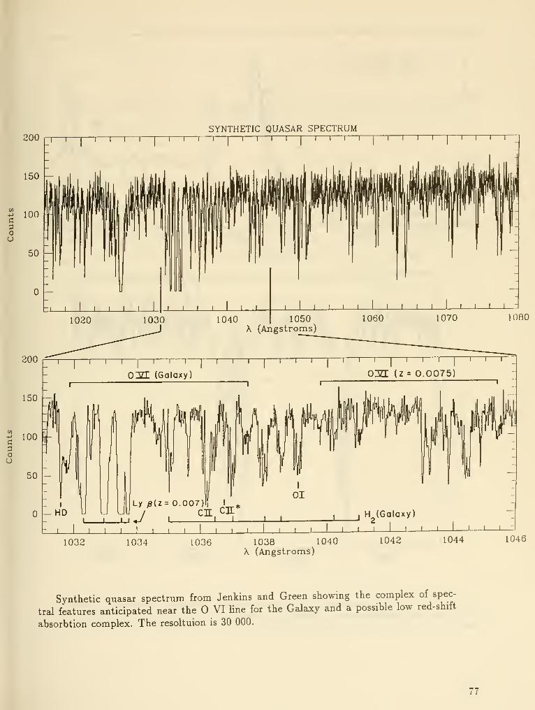
c
ou
200
150 —
100
SYNTHETIC QUASAR SPECTRUM-|—I—I—I—I—I—I—1
—
1—I—I—I I I
I
I \ 1 r
cpou
1080
200
150
100
I
HD uI L
Ly /3{Z= 0.007)on cn'
I I I L J I
H (Galaxy)
I- I II I
I I I I II I I I I I I L I I I I I I I I I 1 L
1032 1034 1036 1038 1040\ (Angstroms)
1042 1044 1046
Synthetic quasar spectrum from Jenkins and Green showing the complex of spec-
tral features anticipated near the VI Une for the Galaxy and a possible low red-shift
absorbtion complex. The resoltuion is 30 000.
77
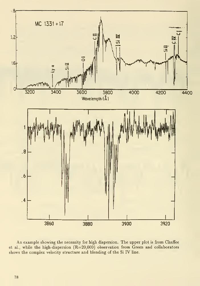
3200 3400 3600 3800 4000
Wavelength (A)
4200 4400
3860 3880 3900 3920
An example showing the necessity for high dispersion. The upper plot is from Chaffee
et al., while the high-dispersion (R=20,000) observation from Green and collaborators
shows the complex velocity structure and blending of the Si IV Une.
78

References
Bechtold, J., Green, R.F., Weymann, R.J., Schmidt, M., Estabrook, F.B., Sherman,
R.D., Wahlquist, H.D. and Heckman, T.M. 1984, ApJ., 281, 76.
Crotts, A.P.S. 1989, ApJ., 336, 550.
Fall, S.M., Pei, Y.C. and McMahon, R.G. 1989, Ap.J.(Utt.), 341, L5.
Foltz, C.B., Weymann, R.J., Peterson, B.M., Sun, L., Malkan, M.A. and Chaffee, Jr.,
F.H. 1986, ApJ., 307, 504.
Khare, P., York, D.G. and Green, R.F. 1989, ApJ., 347, 627.
Lanzetta, K.M., Turnshek, D.A. and Wolfe, A.M. 1987, ApJ., 322, 739.
Sargent, W.L.W., Boksenberg, A. and Steidel, C.C. 1988a, ApJ.SuppL, 68, 639.
Sargent, W.L.W., Steidel, C.C. and Boksenberg, A. 1988b, ApJ., 334, 22.
Schneider, D., Schmidt, M., and Gunn, J.E. 1990, ApJ.(Lett.), in press.
Tyder, D. 1982, Nature, 298, 427.
Walbom, N.R., Heckathom, J.N. and Hesser, J.E. 1984, ApJ., 276, 524.
Yee, H.K.C. and Green, R.F. 1987, ApJ., 319, 28.
York, D.G., Dopita, M., Green, R.F. and Bechtold, J. 1986, ApJ., 311, 610.
79

DISCUSSION
Miller : What is the advantage over the ground of a large space telescope for absorption line studies?
Is it working in the UV on low redshift objects?
Green : Yes, it is the ability to use the diagnostics we know (CIV, SilV, OVI) in the redshift range
where we can also study the galaxy (z = 0.25-0.75). Then we need access to the UV with the same
light-gathering power.
Gunn : The calculations I described about galaxies around quasars indicate that if the absorbers are
galaxies, and dwarf galaxies, they can be seen to redshifts of about 2 with the NGST.
Green : These observations will be key to closing the loop in establishing the relationship between the
absorbers and distant galaxies. I would still emphasize the lower redshift systems, because we would
probably be able to study the galaxies in more detail spectroscopically.
Stockman : Couldn't you use HST or NGST to study the actual clouds seen at redshifts of 2 ~ 2-3?
This would be the complement of your desire to study clouds at redshifts where the galaxies/clouds
can be observed from the ground.
Green : The high redshift clouds can be related to NGST galajcy imaging, as pointed out by Jim Gunn.
In order to understand the metallicity and velocity structure of a cloud in the context of its location
and local history of star formation, we require detailed spectroscopic study of the associated galaxy;
lower redshift galaxies will be much more amenable to spectroscopy with high spatial resolution.
80

USE OF A 16 M TELESCOPE TO DETECT EARTHLIKE PLANETS
Roger Angel
Steward Observatory
University of Arizona
Tucson, AZ
Abstract
If there are other planets similar to the Earth, in orbit around nearby stars
like the sun, they could be detected through their thermal emission, and their
atmospheric compositions measured. A large telescope in Earth orbit is necessary,
cooled to around 80 K. In order to overcome the limitations set by diffraction and
zodiacal background emission, a primary mirror area of some 200 m^ is required,
and an overall dimension of some 20 m. The 16 m telescope under consideration
at this conference is ideally suited to the task. It could be configured as a filled
round aperture, and the required very high contrast ratio could be obtained with
focal plane instruments that block or interfere sections of the wavefront.
Alternatively, the primary surface could be made from four slightly separated 8 mmonoliths. The latter configuration yields the highest resolution and contrast whenoperated as an interferometer, with little negative impact on performance for
direct imaging. A properly optimized telescope should yield spectra of good
quality (A/AX = 100, signal/noise ratio of 50) of earthlike planets as far away as 10
pc, given integrations of a week or so.
Introduction
A popular T-shirt bears the now familiar image of the Earth from space and the
caption, "Good planets are hard to find". It is the sad fact that the exploration of the
solar system has found the Earth to be unique. The differences are perhaps no more
clearly evident than in the beautiful spectra of thermal emission obtained by Hanel
and his colleagues and collected together in figure 1. Mars atmosphere shows only
carbon dioxide, Venus has also absorption by sulfuric acid. Only in the Earth's
spectrum are found the features of water and oxygen in the form of ozone. Thestrong features of methane and steeply rising spectra of the outer planets reflect their
very cold and inhospitable temperatures.
Today we seem to be on the brink of finding planets, albeit of the most
massive type, around nearby stars. Astrometric and spectroscopic techniques with
modern detectors have the capability to detect the motion of stars that would indicate
massive orbiting planets. However, direct imaging that could give more information
than simply mass and orbital motion, even of Jupiter sized planets of the nearest stars,
is at the very limit of sensitivity of the Hubble space telescope. In this paper we will
81
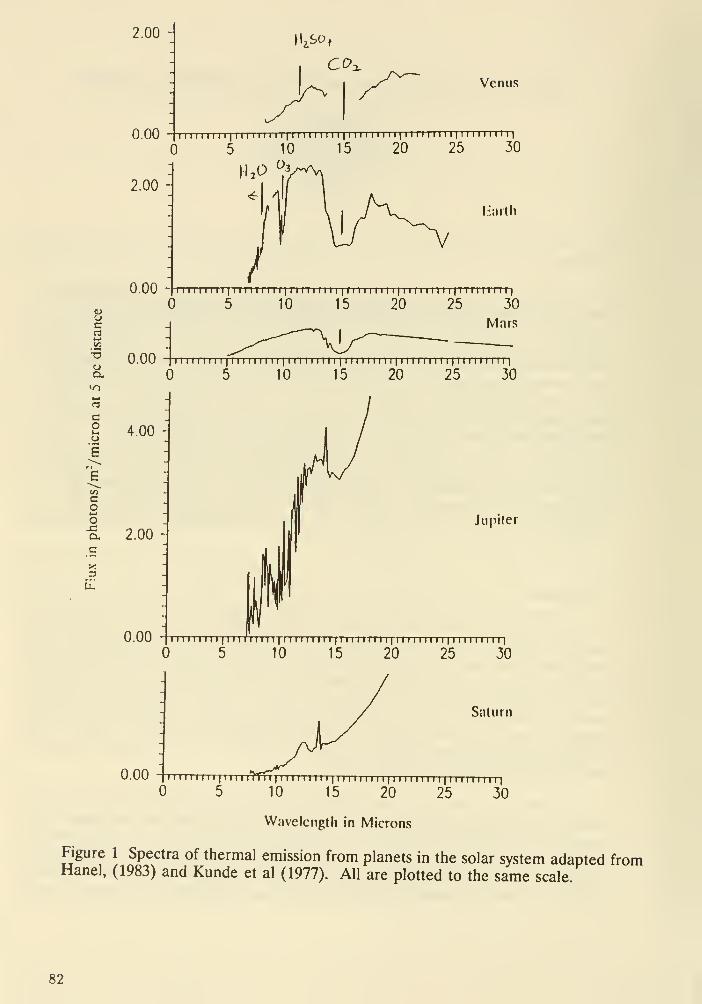
2.00
0.00
2.00
Venus
1 1 1 1 1 1 1 1 1
[II 1 1 1 II 1
11 1 r 1 1 1
1
1 1
1
1 1 1 M 1 1 1 1 [| 1 1 II 1 1 1 1 i|ii II 1 1 II i|
5 10 15 20 25 30
1 12^ ^!
lijuth
0.00 1 1 1 1 1 1 1 1 1 1 [1 1 1 1 1 1 1 1
11 1 1 1 1 1 1 1 II I II 1 1 1 1 1
1
1 1 1 1 1 1 1 1 II1
1 1 1 1 1 1 1 1 11
1
5 10 15 20 25 30
Mars
"I iiiiiiii lii i riiiii 1 1 iiiiiii I [111 1 111 1 i|ii I i nn i
|iiiiiiiii|
5 10 15 20 25 30
0.00
Siitiirn
" n 1 1 II I II I m 1 1 1 1
1
1 n n 1 1 1 1 1 1 1 1
1
I I I n 1 1 n 1 1 1 [ II 1 1 n I MI
5 10 15 20 25 305 10 15 20 25 30
Wavelength in Microns
Figure 1 Spectra of thermal emission from planets in the solar system adapted fromHanel, (1983) and Kunde et al (1977). All are plotted to the same scale.
82
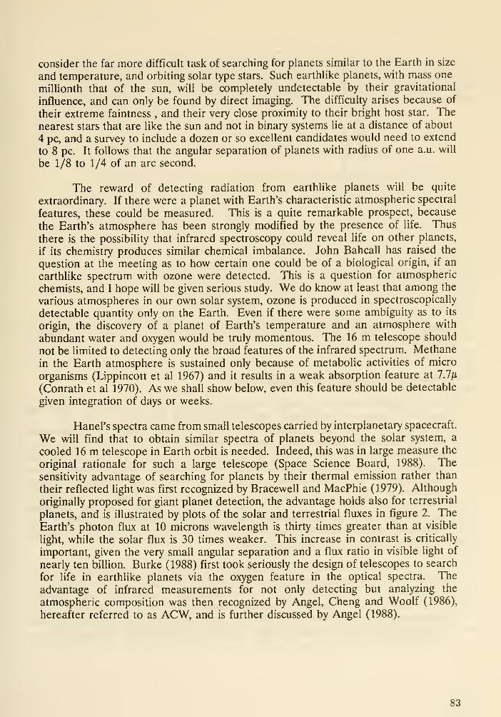
consider the far more difficult task of searching for planets similar to the Earth in size
and temperature, and orbiting solar type stars. Such earthlike planets, with mass one
millionth that of the sun, will be completely undetectable by their gravitational
influence, and can only be found by direct imaging. The difficulty arises because of
their extreme faintness , and their very close proximity to their bright host star. The
nearest stars that are like the sun and not in binary systems lie at a distance of about
4 pc, and a survey to include a dozen or so excellent candidates would need to extend
to 8 pc. It follows that the angular separation of planets with radius of one a.u. will
be 1/8 to 1/4 of an arc second.
The reward of detecting radiation from earthlike planets will be quite
extraordinary. If there were a planet with Earth's characteristic atmospheric spectral
features, these could be measured. This is a quite remarkable prospect, because
the Earth's atmosphere has been strongly modified by the presence of life. Thus
there is the possibility that infrared spectroscopy could reveal life on other planets,
if its chemistry produces similar chemical imbalance. John Bahcall has raised the
question at the meeting as to how certain one could be of a biological origin, if an
earthlike spectrum with ozone were detected. This is a question for atmospheric
chemists, and I hope will be given serious study. We do know at least that among the
various atmospheres in our own solar system, ozone is produced in spectroscopically
detectable quantity only on the Earth. Even if there were some ambiguity as to its
origin, the discovery of a planet of Earth's temperature and an atmosphere with
abundant water and oxygen would be truly momentous. The 16 m telescope should
not be limited to detecting only the broad features of the infrared spectrum. Methane
in the Earth atmosphere is sustained only because of metabolic activities of micro
organisms (Lippincott et al 1967) and it results in a weak absorption feature at 7.7/i
(Conrath et al 1970). As we shall show below, even this feature should be detectable
given integration of days or weeks.
Hanel's spectra came from small telescopes carried by interplanetary spacecraft.
We will find that to obtain similar spectra of planets beyond the solar system, a
cooled 16 m telescope in Earth orbit is needed. Indeed, this was in large measure the
original rationale for such a large telescope (Space Science Board, 1988). The
sensitivity advantage of searching for planets by their thermal emission rather than
their reflected light was first recognized by Bracewell and MacPhie (1979). Although
originally proposed for giant planet detection, the advantage holds also for terrestrial
planets, and is illustrated by plots of the solar and terrestrial fluxes in figure 2. The
Earth's photon flux at 10 microns wavelength is thirty times greater than at visible
light, while the solar flux is 30 times weaker. This increase in contrast is critically
important, given the very small angular separation and a flux ratio in visible light of
nearly ten billion. Burke (1988) first took seriously the design of telescopes to search
for life in earthlike planets via the oxygen feature in the optical spectra. The
advantage of infrared measurements for not only detecting but analyzing the
atmospheric composition was then recognized by Angel, Cheng and Woolf (1986),
hereafter referred to as ACW, and is further discussed by Angel (1988).
83
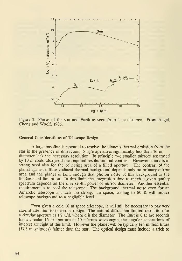
12 r--| —1—I I t
-2
—r — T— I f f""*"* »
—
f~'
^_. Sun
EarthOg, C02.
_l I I L_
00 05 15
log X (nm)
Figure 2 Fluxes of the sun and Earth as seen from 4 pc distance. From Angel,
Cheng and Woolf, 1986.
General Considerations of Telescope Design
A large baseline is essential to resolve the planet's thermal emission from the
star in the presence of diffraction. Single apertures significantly less than 16 mdiameter lack the necessary resolution. In principle two smaller mirrors separated
by 10 m could also yield the required resolution and contrast. However, there is a
strong need also for the collecting area of a filled aperture. The contrast of the
planet against diffuse zodiacal thermal background depends only on primary mirror
area and the planet is faint enough that photon noise of this background is the
fundamental Umitation. In this limit, the integration time to reach a given quality
spectrum depends on the inverse 4th power of mirror diameter. Another essential
requirement is to cool the telescope. The background thermal noise even for anAntarctic telescope is much too strong. In space, cooling to 80 K will reduce
telescope background to a negligible level.
Even given a cold 16 m space telescope, it will still be necessary to pay very
careful attention to telescope design. The natural diffraction limited resolution for
a circular aperture is 1.2 \/d, where d is the diameter. The Umit is 0.15 arc seconds
for a circular 16 m aperture at 10 microns wavelength, the angular separations of
interest are right at this limit. However the planet will be typically ten million times
(17.5 magnitudes) fainter than the star. The optical design must include a trick to
84

strongly suppress the diffracted light from the star, if there is to be any hope of
finding a planet. It is also necessary to pay very careful attention to the accuracy of
the mirror surfaces, for tiny figure errors will produce weak features in the diffraction
pattern that masquerade as planetary images. In the following sections we consider
in more detail these technical aspects.
Two Ways to Control Diffraction in a Filled Circular 16 m Telescope
Focal plane instruments are needed to alter the normal Airy pattern of a 16
m telescope. Two options are available. The transmission or phase across the pupil
can be modified to produce very dark regions in the diffraction pattern (apodization).
Alternatively an interferometric beam-splitter can be arranged to cancel the starlight
at one of a pair of foci.
Apodization is generally used to suppress the far wings of the diffraction
pattern. What is wanted in the present case is strong suppression of the diffracted
energy in a region as close as possible to the central maximum. ACW proposed a
new method to this. All that is needed is to mask out the pupil in an annular region
from radius .66 to .9 of the full aperture. This has the effect of making the first dark
ring of the diffraction pattern extremely dark over a considerable width. The effect
has been demonstrated recently in the laboratory by Peter Wizinowich, and is shown
in figure 3. A spherical mirror of 2.4 m radius of curvature was masked with a full
aperture of 16 mm. Two point sources at .633 microns wavelength, one a thousand
times brighter than the other, were placed near the center of curvature, and the
nearby image recorded directly with a CCD camera. Figure 3a shows the image with
the two sources well separated. Over most of the field the apodization causes
stronger diffraction rings than are in the Airy pattern, but the first dark ring is wider
and much deeper. In figure 3b the weaker source has been moved close in, to an
angular separation of 2 X/d. It is clearly visible at this separation of only 1.7 times
the Rayleigh criterion, despite the very large intensity ratio. The analysis by ACW of
this apodization shows that suppression of the diffracted energy in the dark ring to
3x10* of the peak intensity is realized, over an area several times larger than the
image core.
The apodization method is simple and very powerful, particularly in allowing
a search of a complete annular region in one image. However, it will not allow
detection of planets closer in angular separation than about 1.6 X/d, or 0.2 arc seconds
at 10 microns wavelength. Its capability to find planets with 1 au orbits will be limited
to only a few solar type stars. It is possible at least in principle to obtain nearly as
strong star suppression still closer, by using interferometric instrumentation at the
focal plane of the 16 m telescope. Suppose that the full aperture is masked into two
elliptical apertures, as shown in figure 4a. The diffraction pattern then has a central
narrow bright fringe, with the first dark fringe lying only 0.9X/d from the central peak
(0.11 arc seconds). The resolution is higher, but the dark fringe is too narrow to be
useful. In this case, as in the classic Michaelson stellar interferometer, the
interference fringes between the two apertures are formed in the focal plane.
85

Much more efficient suppression of the stellar flux is obtained without loss of
resolution if the two wavefronts are exactly superposed with the aid of a semi-
transparent beam splitter. In this case the fringes are projected onto the plane of the
sky, and a point stellar source centered on a dark fringe gives no light at all at the
focus where the interference is destructive. All the energy appears from constructive
interference in the other beam. The situation is Reversed for a planet located at angle
0.9 A/d from the star. This is the principle of the interferometer proposed by
Bracewell and MacPhie (1979).
t
Planet
Figure 3a and 3bLaboratory images of
sources differing by Vf in
intensity, obtained with a
mirror apodized as
described in the text.
The weaker source is
marked "planet".
t
Planet
86

V
Figure 4a Apertures in
the pupil of a 16 mtelescope that define
the two elements of an
interferometer.
I Refractive Path Compensators
Beam Splitter Figure 4bInterferometer to
combine the two
adjacent beams.
The theoretical limit of starlight suppression for this type of two element
interferometer of spacing s is set by the finite angular size of the parent star. Theresponse at angle 6 off the null axis varies as sm\i[ds/\) where s is the spacing
between centers of the interferometer elements. Suppose the planet is located at a
maximum, and the center of the star is on the null axis. If the star has the samediameter as the sim, and the planet is at the furthest separation of a 1 a.u.radius
orbit, then the stellar light will be reduced by a factor 1.3x10', compared to the in-
phase signal. This background is about 4 times worse than in the apodization case.
Realization of the interferometric null in practice imposes a severe constraint on
pointing. If the telescope points off by one stellar diameter, about 1 miUiarcsecond,
the uncancelled image will brighten by an order of magnitude, and be about 1000
times brighter than the planet. In practice it will not be possible to point the 16 mtelescope to the required accuracy, and it will be necessary to servo control the null
via optical starlight, adjusting the interferometer path lengths to the required accuracy
of a few nanometers.
87

Some care is needed to devise a two beam interferometer for the present case,
in which the individual diffraction patterns are not much larger than the fringe
spacing. In the scheme of Bracewell and MacPhie, for example, the individual images
of an off-axis object do not overlap, but separate on either side of the residual star
image. This is of little consequence for widely spaced interferometer elements. In
the present configuration, it prevents full constructive interference of the planet's flux,
and increases the image area and hence sky background noise. Not only is the signal
to noise ratio degraded, but it may be impossible in practice to distinguish a planet
from the much brighter zodiacal light local to the star, which will be symmetrically
distributed on either side of the star. The same type of problem arises in the rotating
shearing interferometer, as described by Diner (1989) at this conference.
An interferometer optimized for two very close elements as would be derived
from a single filled aperture is shown in figure 4b. It would be used in conjunction
with an afocal secondary. The off-axis images are exactly superposed in this design,
and are given simply by the single elliptical aperture diffraction pattern whose overall
intensity is determined by the sin^ fringes. The design has pathlength compensators
incorporating refractive materials of different dispersion. These would be chosen so
that the destructive interference at one focus is achromatic over a useful range of
wavelengths. The phase change of n on reflection by a metal could perhaps be used
for this purpose, but we note that the phase difference at a metallic beamsplitter used
in the Bracewell and Macphie interferometer is not tt, as was desired.
What is the Optimum Optical Configuration for the 16 m Telescope?
We have so far considered designs based on a filled circular aperture. A 16
m telescope is too big to be built and launched in one piece. It would have to be
assembled from mirror segments. Diffraction spikes would be produced by the
segment edges as well as the spider vanes supporting the secondary. Is it possible
to redeploy the same collecting area to do a better job? Insofar as zodiacal
background is the limiting factor, there is no advantage to be gained. Resolution
can be improved, for example, by arranging the aperture as a two element array.
With two separated 11.3 m mirrors, it would be possible to make narrower fringe
spacing, and thus have the resolution to search more distant stars. However, there
is a large number of candidate systems closer than 10 pc, and the very faint signal
from earthlike planets beyond this distance would lead to extremely long and difficult
observations, even if the interferometer gave adequate starlight suppression. For the
nearer systems, there is a distinct disadvantage in using two element interferometer
baselines longer that are needed to give more than half a fringe spacing between star
and planet. If there were one and a half fringes, for example, then the star disc gives
nine times more uncancelled background emission.
An arrangement that eliminates diffraction spikes, and gives excellent star
rejection down to planet separations of 0.1 arc second (at lO/x wavelength) is shownin figure 5b. The telescope is made from four 8 m circular monolithic mirrors,
arranged in a diamond pattern. These mirrors would be figured as off-axis segments
88

of a single paraboloidal surface. A single paraboloidal secondary would be used to
make an afocal telescope, which would directly feed an interferometric beamcombiner for planetary work. This arrangement is preferred over an MMT style
telescope, because there is no obscuration by individual secondaries and the field of
view is larger. The
y^^ -^t-
TiX
Figure 5a Filled 16 m circular
aperture.
k-n, -^
Figure 5b Diamond configurations
with four 8 m circular elements.
wavefronts from the two pairs of diagonal elements would be superposed in phase
with interferometers like that shown in figure 4b, and the resulting wavefronts then
combined out of phase with a third interferometer. The effect is to superpose on the
sky two sets of sine-squared fringes at oblique angles.
If the mirror centers are at distances r, and r^ from the telescope axis, then
the intensity of the image of a point source at angle B to the axis and position angle
is given by
I = 1/4 {cos (27rr,^cos0/A) - cos(27rr/sin0/A)}'
89
This reduces near the axis to
1= 1/4 (TT^/Ay (r/cos'^-r/sinW, [e<<\/T]
The dependence of I on 9^ results is very efficient suppression of the star.
Thus for r~8 m, and X ~10/xm, I is less than 10* for ^ < 4 mas and < 10' for ^ < 1
mas.
The ratio tJt^ in diamond pattern is chosen so that no matter what the angular
separation between planet and star, as long as it is above some minimum, the
telescope can be oriented so that the planet lies close to an interferometric maximumwhen the star lies on the null axis. We find that with r, = 8 m and r, = 4.85 m,
points in the pattern with I > 0.6 can be found for all angular radi >. 0.1 arc second
(for \ = 10/im), with I being typically > 0.9. (Complete constructive interference of
all four wavefronts corresponds to I = 1).
Performance Estimates
The effect of mirror imperfections and misalignment will be to give systematic
errors. Imperfectly cancelled starlight can easily mimic the appearance of a planet.
It will be necessary to repeat measurements to check for and cancel these errors,
which cannot be estimated without detailed system modelling. We can estimate here
the errors due to photon noise in the thermal background, which are quite
predictable, and set an absolute lower limit to the integration times that will be
needed to get reliable data.
In the interferometric configurations, if the beamsplitters are ideal with 50%reflected and transmitted energy, both the signal from the planet and the photon
noise from a diffuse zodiacal background remain the same as for a single dish with
the same total area. All the flux collected from the planet appears in a single image
at the focal plane where there is constructive interference. The interferometric image
has the larger angular size of the single element diffraction pattern, but the zodiacal
background does not interfere constructively, and is no stronger than it would be for
one interferometer element. Thus in the case of the diamond array of four 8melements the image has four times the angular area of that for a 16 m filled aperture,
but the background brightness is four times fainter, because each beam has passed
twice through a semi-transparent beamsplitter.
Because zodiacal background is diffuse, it cannot be avoided by interferometry
or apodization. We must take into account the emission both from within our ownsolar system, which is accurately known, and from the system under investigation. Thelatter is unknown, but for purposes of estimating the photon noise background wefollow ACW in assuming a system just like the solar system. The total background
is then 3 times the local level, integrating along the line of sight out of our system.
90
into the new one and out again. The zodiacal emission in our own solar system is
well represented by a grey body of temperature 275K and optical depth 7x10*.
Under these assumptions, the flux incident from the total zodiacal background
on a 16 m telescope in a beam large enough to capture the central bright spot of the
Airy pattern is 23,000 photons/sec in a 1/i bandwidth at 10^ wavelength. The photon
flux from a planet the same as the Earth incident on the telescope is about 500
photons/sec if it is at 4 pc distance, 80 photons/sec if it is at 10 pc.
Suppose that a planet has been detected, and a spectrum of quality adequate
to detect features like those in figure 1 is to be obtained. We will assume that a
resolution of X/AA = 100 and a signal to noise ratio of 50 is required. An ideal 16
m system with no losses, detecting of the central Airy maximum with 100% quantumefficiency, would require an integration time of an hour for the planet at 4pc, 6 hours
at 10 pc. In reality, the combined effects of optical losses and optical imperfections
that result in imperfect star cancellation will probably increase the necessary
integration time by an order of magnitude. Furthermore, if the exact phase
relationships for star cancellation cannot be maintained over a broad wavelength
range, then a full spectrum must be built up from separate integrations of smaller
spectral regions. Even so, a respectable spectrum of an earthlike planet as far away
as 10 pc could be obtained in an integration period of a week or two.
Over a period of years the telescope could complete a spectroscopic survey of
tens of planetary systems like the solar system, if they are present. If a planet werefound with a spectrum resembling Earth's, longer exposures could be used to search
for weak features such as methane. The methane feature at 7.7 microns wavelength
in the Earth's spectrum is about 0.03 microns in width and 10% deep. Integrations
some five times longer than used for the routine survey spectra would be able to
detect even this feature.
It is on the basis of these performance estimates that we believe the collecting
area of a 16 m telescope, or close to it, is required. If the effective diameter were
halved, for instance in an array of four 4 m elements, the integration time would be
increased by a factor 16, and become prohibitively long. A telescope at this size
could detect earthlike planets, but would not be able to carry out spectroscopic
analysis of good quality. Under any circumstance, a telescope to overcome the limits
of diffraction must be based on a large and extremely rigid structure. Given this, it
would not save much money to cover it only with small mirror area, but it wouldseverely compromise performance.
Impact on Normal Telescope Operation
A 16 m telescope has enormous value for many aspects of astronomical
research. It is fortunate that the requirements imposed to make the telescope suitable
for earthlike planet studies enhance rather than compromise the performance for
91

other observations. To get the nearly perfect diffraction limited performance at lOfi
wavelength, the surface quality (on large spatial scales) is such as to realize normaldiffraction limited imaging at 0.1/i (ACW).
For normal imaging and spectroscopy, the afocal beam from the telescope
would be brought to a direct focus with an auxiliary telescope in place of the
interferometric beam combiners. The diffraction pattern of the diamond array has
higher resolution than that of a 16 m circular aperture, but has significant side lobes.
A comparison is given in figure 6. The fraction of the total energy in the central
maximum is 84% for the Airy pattern compared to 60% for the diamond array. Fourof the sbc prominent side lobes each contain 5% of the total energy, with 2% in each
of the remaining two. For imaging and background limited spectroscopy, the
advantage of higher resolution offsets the disadvantage of lower concentration. Only
a modest degree of image cleaning would be required to remove to sidelobe patterns.
The full width at half maximum power in visible light (5000A) is 7.7 mas for the 16
m filled aperture, and 5.2 mas for the diamond array. Interferometric methods would
allow a doubling of this resolution, as would halving the wavelength of observation.
New Technology
The major advance in optical technology required to build the telescope is in
mirror fabrication. Off-axis segments need to be polished to very high accuracy.
The stressed lap method (Martin et al. 1988) is extremely promising, for 8 m or
smaller segments, but needs to be demonstrated explicitly in the off-axis case. Glass
honeycomb substrates with zero thermal expansion at 70-80K need to be developed.
Borosilicate glass of suitably chosen composition has this property. The facilities for
fabrication into 8 m substrates are now being developed (Angel 1989) and could be
upgraded to handle the more refractory compositions needed for this application.
Work is needed to design an interferometric beam combiner in which phase
shifts are controlled to the required very high accuracy, and on mechanical structure
and active alignment techniques. The telescope with its thermal baffling is a large
structure that will require assembly in orbit or on the Moon. If monolithic 8 msegments are used, then rockets large enough to contain them will be needed.
Given the present state of technology, none of these tasks is beyond our reach.
The search for a planet like our own is a project of immense appeal, and could be the
central goal of an international space telescope project, as envisaged by Bahcall et al.
(1989).
92
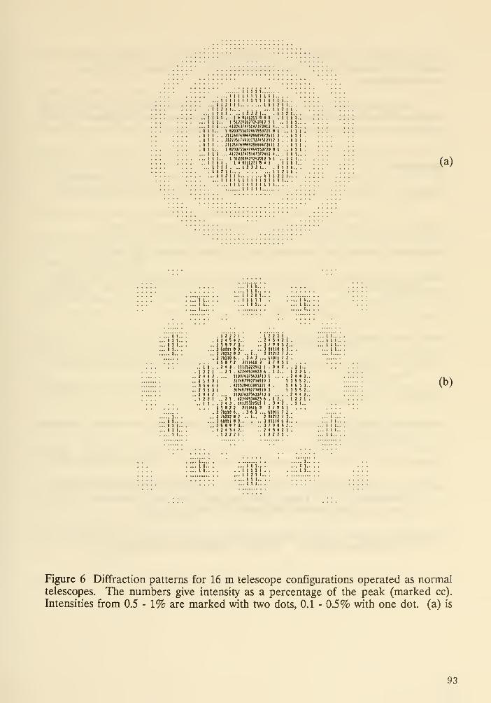
I I
I I
I I
I I..
I I
I I
I I
I 1..
IllIIIII
I ;
I I
I M I 1
I I I I I I I I I I I..
I 1 I 1 I I I t 1 I I I I
i I I 1 I Ill]Ml I I :
I . .. I J ) ! I.. .1I < SIMZII 4 < I
1 mivizmmii 5 I .
.. 'tiiiviiwi7iia I..
I «0!J!S»?'<H5SJ?2O J I
, Ji;jisi;n;cc?;?'5mi! 3
, J1U6"'H»»«»««<<!SII 1
1 ««);««;<*«$j;:o « i
'\ii<vmwv}<ii I..
1 SI!!0!SM!*»1? S 1 .
I • 91112111 • 1
II. .. 1 J 3 2 1.. .1III II1 2 I I I I I 1 2 I
I I I I I I 1 I I I I I I I
. I I I I I I I I 1 I I..I 1 t 1 1
I.. .
1 1 .
2 I..I 1 I.
I I 1.
I I I.
..II.11.11. I I
..111I I I.
I I I.
1 I I.
2 I..(a)
... 1 1 1..
....II I.
... I I 2 I I
. . I I I I I
... I I I.
III.111.I I..
... I..
II..III.III.
... I I.
.. I I
.12 2 1
. 2 I < .
2 s s :
. 3 S t I
.255:
. 2 < < I
.12 2 1
.. I I
1 2 2
I 4 5
S t 1
tlOIIII21271110
.. 2 I
2 < 3
[5)2I ;iiio
I 21212
I tlOII
I 5 « «
I 2 < 5
.12 2
1.
».. . 3 « ) ..
2 3II1»II 3
11125322511
. 123HSJH23ll3);53'5»33;imwnmw«1S2«CCM522I3n<87r»27148rIi3s;s375»)3;i:. t2]<*53«23. 1I125J2251I2 3III6I1 3
i.. . 3 » 3 .
1 2 .. 1..
a 3
2 3..
• 2..
2 1.
2 2 2 1.< 5 < 2 I
2 9 « 5 2
9III9 t 3
«I212 ' 3
ilOtI 1 2
2 2 9 5 1
.312.
. 1 2..
. I 2..
.312.2 7 9 5 1
61011 7 2
91212 7 3
91110 t 3
7 19 5 2
4 5 4 2 1
2 2 2 1.
. 1 I..
12 2 1..2(42..13 5 5 2..
14 6 5 3..
13 5 5 2..
.2442.12 2 1.
1 I..
.11...
.111.111.
(b)
111.III.
.11...
... 1 1 1.
.1111
.112 1
... I I I.
... I I I.
Figure 6 Diffraction patterns for 16 m telescope configurations operated as normaltelescopes. The numbers give intensity as a percentage of the peak (marked cc).
Intensities from 0.5-1% are marked with two dots, 0.1 - 0.5% with one dot. (a) is
93
the Airy pattern for a filled 16 m aperture, (b) is the pattern with the same angular
scale for a diamond array of 8 m telescopes with r^ = 8 m and r^ = 4.8 m.
Acknowledgments
I am grateful to Neville J. Woolf for valuable discussions of this topic, to Peter
Wizinowich for obtaining the laboratory apodized images, and to Michael Hart for
assistance in preparing the montage of planetary spectra.
References
Angel, J.R.P., 1988, in "Bioastronomy -- The Next Steps," ed. G. Marx, Kluwer,
153.
Angel, J.R.P., Quarterly Journal Royal Astronomical Society, in press.
Angel, J.R.P., Cheng, A.Y.S. and Woolf N.J., 1986, Nature, 232, 341.
Bahcall, J.N., Giacconi, R., Rees, M., Sagdeev, R. and Sunyaev, R., 1989, Nature
339 . 574.
Bracewell, R.N. and MacPhie, R.H., 1979, Icarus, 38, 136.
Burke, B. F. 1986, Nature . 322, 340.
Conrath, B.J., Hanel, R.A., Kunde, V.G. and Prabhakara, C, 1970, J. Geophys.
Res. 75, 5831.
Diver, D.J., 1989, These Proceedings.
Hanel, R.A., 1983, in "Spectrometric Techniques", Volume 3, p. 43, G.A. Vanasse
ed.. Academic Press.
Lippincott, E.R., Eck, R.V., Dayhoff, M.O. and Sagan, C, 1966, Ap. J., 147, 753.
Martin, H.M., Angel, J.R.P. and Cheng, A.Y.S., 1988, Proceedings of the ESQConference on Very Large Telescopes and Their Instrumentation, ed. M.H.Ulrich, Garching, Federal Republic of Germany, 353.
Space Science Board, 1988, in "Space Science in the 21st Century: Imperatives for
the Decades 1995-2015". National Academy Press, Washington, D.C.
94
DISCUSSION
Bahcall : How do you know that ozone is only the result of life.
Angel: The oxygen in our own atmosphere is now taken to be due to the presence of life. However,
it would be good to look more closely at this approach.
Pilcher : It might also be good to look at other molecules (e.g., methane) that appear to be in
chemical disequilibrium in our oxidizing atmosphere. These molecules in disequilibrium may also be
useful diagnostics of life. Methane, for example, is in disequilibrium by 7 orders of magnitude while
for oxygen it is about a factor of 20.
Nelson : You stated that the gaps are not important. Can you expand on that?
Angel: The energy &om the gaps spreads out over a large area - and so with narrow gaps (say 2%
of the area) the level of the scattered light at the 0.25" ring should be small, even compared to the
highly attenuated starlight.
Unidentified : Doesn't working in the visible where the Airy disk is so much smaller offset the contrast
gain in the Infrared? That is, doesn't the 400X gain in the Airy disk area offset the 600x gain for the
IR in contrast?
Angel: The contrast is not only better in the IR, but the photon flux is much higher, and this
observation is photon-flux limited. The 10 micron O3 line is also much stronger than the visible O2
line.
Dlingwortli: One would also be concerned about the need for a surface that is signiflcantly better
than that required for the 10 micron observations - and that is already tough.
FalL Could you do better by looking at brighter (earlier-type) stars at larger distances from the stars.
Angel: The problem is that the number of available stars is extremely smeill, and that it gets very
difficult with bright stars.
Rehfield : Has scatter from the structure been considered in the telescope design?
Angel: Most of the complex structure is outside of the aperture and field of view. Only simple
secondary supports contribute scatter.
Korsch : You need to consider the scattering properties of the additional optics to make the pupU
plane for the apodizer.
Angel: It is really quite straightforward because a pupil plane can be obtained very simply most
anywhere with such a small field of view (0.25").
95


Session 3
Large Optics: Ground-based Developments
97


The Keck Telescope Project
Jerry Nelson
50-351 Lawrence Berkeley Laboratory
Berkeley, CA 94720
Introduction
The Keck Observatory is a project to build a 10-m optical and infrared telescope for
ground based astronomy. The primary is composed of 36 hexagonal segments that
together form an f/1.75 hyperbola. The segment positions are actively controlled to remove
the adverse effects of gravitational and thermal deformations on the supporting steel
structure.
Details of the project are described in a number of internal reports and memos and
periodic status are given in recent SPIE proceedings. A review of the characteristics of the
Project with emphasis on the segment fabrication and the active control system was
presented at this conference. Since most of this information is available in the recent SPIE
proceedings information of a general nature is not repeated here. We only repon here some
interesting aspects of segment fabrication that may be of interest for large high accuracy
telescopes in space.
Segment Fabrication
Our mirrors are being polished at Itek Optical Systems in Lexington, MA. They are
polished as circular mirrors using stressed mirror polishing (SMP). With this technique,
spheres are polished into an elastically deformed mirror so that when the externally applied
deforming forces are removed, the sphere relaxes into the desired off axis section of a
hyperboloid. Our hyperboloids vary up to about 100|im from a sphere.
After SMP the mirrors are cut into hexagons. Our experience is that the mirrors
warp a significant amount from this cutting (0.5|im) and this error along with the
imperfections in the polishing itself makes the mirror unacceptable optically. Our
specification is that the mirrors should concentrate 80% of the light into 0.24 arcsecond
diameter. After cutting the mirrors are typically about five times worse than this.
Originally our plans were to test these hexagons and make final correction of the
surface using a technique called Computer Controlled Optical Surfacing (CCOS) where a
small (10cm) tool is driven over the surface with a dwell time controlled by computer to
remove the high spots. We tried this technique with two mirrors and found the technique
to be wanting for our application.
There were several problems with CCOS. First, the method only converged slowly
to the desired surface, so many (-10) polish-test cycles were necessary to produce the final
mirror. This of course makes the process relatively expensive. Second, the polishing
process generally roughened the edges of the mirror up rather severely. Edges here mean a
region about the diameter of the tool (10cm) wide going around the entire segment
perimeter. This is about 25% of the segment surface area, so it is important. The edge
surfaces had high spatial frequency errors with amplitudes in the 50nm rms range. This led
to substantial broadening of the image size. Finally, even in the interior there were
apparent grooves or lines caused by the tool motion pattern. These could be easily seen in
99

interferograms of the surface. Their amplitude was relatively small (~10nm ) so they were
not a concern for observations in the red end of the spectrum, but in the blue-ultraviolet, it
became a concern.
As a result of these difficulties we have chosen to make improvements to our mirror
surface by deforming them gendy with a set of corrective forces applied to the back of the
mirror through our passive suppon system. This approach has some merit because the
largest part of the surface error is in the form of very low spatial frequency errors that can
be removed with these corrective forces. We call this set of springs that applies the
correcdve forces "warping harnesses". Our experience is that warping harnesses are very
inexpensive and stable and they correct most of the errors of interest. At the moment,
having made six mirrors, we suU are about a factor of two away from our final polishing
goals. We hope that as our fabrication experience grows our image quality will improve to
the desired level.
DISCUSSION
Johnson: What is the reliability and performance life of the actuators on the segments of the KeckTelescope?
Nelson: The most significant problem noted is the possibility of leaking hydraulic fluid. Initially,
many leaks were noted. Tightening up eliminated the leaks for now. In operation, it may be necessary
to replace some actuators periodically. This replacement (and leakage) would be a problem in space,
much more than on Earth.
Breckinridge : How much force do you need on your warping harness?
Nelgon : We can safely apply forces up to about 300 N per support point. Typically we warp our
mirrors with forces a factor of 5 less than this.
Manhart : Do you warp each mirror as it is being tested in its own harness, then mount it in the
telescope and hope that it doesn't change? How often do you check its figure?
Nelson : Each mirror is tested after cutting at Itek. Our experience with warping harnesses is that their
performance is predictable to within measurement errors. We can (and will) also test each segment in
the telescope using a Hartmann-Shack camera with 240 points/segment.
Swanson : Is the Hartman test sufficient to phase the primary mirror in an absolute sense? You are
measuring relative edge developments rather than absolute piston errors.
Nelson : Yes, it is adequate. The Hartman test uses four colors determined by filters to eliminate
fringe ambiguity.
Korsch : Are the segments cut slightly diflferent according to their position on the surface, as regular
hexagons do not ideally fill a parabolic surface?
Nelson : The segments appear as regular hexagons as seen by a star. Viewed normsd to the opticeJ
surface, one sees the segments are actually non-regular by typically few millimeters.
Kahan : Can you provide ball park segment production costs for generating/polishing and coating
boules?
Nelgon : The boules would go for about $100k each, fabrication would be about $50k, and coating
(aluminum) would be minor. All this presumes successful continued use of the warping harness.
100

Stressed-lap Polishing
H. M. Martin and J. R. P. Angel
Steward Observatory
University of Arizona
Tucson, AZ 85721
Abstract
We present a method for polishing fast aspheric mirrors to high accuracy. It is based
on an actively stressed lap whose shape is changed continuously make it fit the mirror
surface as it moves across that surface and rotates. A stressed lap 600 mm in diameter
has been built to polish a 1.8-m f/1 paraboloid. It consists of a rigid aluminum disk which
changes shape continuously under the influence of 12 moment-generating actuators. These
actuators are programmed to produce the shape changes necessary to give the correct off-
axis parabolic surface at all times. In this paper we describe the principles and design of
the lap, and progress to date in polishing the 1.8-m mirror.
1. Introduction
At the meeting Angel gave a discussion of stressed lap polishing as part of a more
general description of the Columbus project. The Columbus telescope is the largest planned
by the US community, to be located at 3200 m elevation on Mt. Graham in Arizona. It will
have two 8 m mirrors on a common mount, each having a focal ratio of 1.2, and an image
quality of 0.125 arcsec FWHM. First light (for the first mirror) is projected for 1994. This
report focuses only on the mirror polishing method to be used for the Columbus telescope,
which is also of direct relevance to future space telescopes. A recent description of the
Columbus and other ground-based telescopes is given by Angel et al. (1989).
Looking beyond the Hubble telescope, it is clear that telescopes in space will need
mirrors that are not only larger, but also smoother and more accurate. The natural
short wavelength limit for normal-incidence telescopes is at 91 nm. Diffraction-limited
performance at this wavelength, with a Strehl ratio of 90%, requires a surface accuracy
of 2 nm rms. Very much higher Strehl ratios, > 1 — 10"^, are needed to avoid scattered
light for the detection of Earthlike planets at 10 /xm wavelength. In this case a surface
accuracy of 2.5 nm rms must be maintained over the largest spatial scales. To avoid
diffraction spikes, the mirror surfaces should ideally be off-axis segments of an aspheric
parent surface. For compact telescopes with such optics, the mirror surface will also be
strongly aspheric.
Mirrors are polished to high accuracy in an iterative process of measurement followed
by corrective removal of material. Progress in optical metrology recently has been very
great, and a moderate extension of present practice will allow even large surfaces to be
measured more accurately than the above specifications. There is a problem, however, in
removing material, even if we know where it needs to comie off. The desired combinations
101
of size, smoothness, accuracy, asphericity and lack of axisymmetry are well beyond the
present state of the art in polishing, and will remain impossible with almost all existing
polishing techniques.
The method of stressed-lap polishing holds the promise of solving all these problems. It
is currently being tested for the first time, in the manufacture at the Steward Observatory
Mirror Laboratory of the primary mirror for the Lennon Telescope being built by the
Vatican Observatory and the University of Arizona. This mirror is 1.83 m (72 in) in
diameter with a vertex radius of curvature equal to 3.66 m (144 in) and conic constant
equal to —0.996. Thus the mirror is slightly ellipsoidal, for use in an aplanatic Gregorian
telescope, but is virtually an f/1 paraboloid. The surface has a peak-to-valley deviation
from the best fitting sphere of 445 /Ltm. The Vatican mirror forms a stringent test for the
Columbus (and Magellan) telescope mirrors, which at 8 m and f/1.2 have not much larger
absolute tisphericity (1.1 mm peak to valley deviation from the best fitting sphere). For
comparison, the fastest 4-m class mirror polished to date has about 5 times less asphericity
than the Vatican mirror.
2. Mirror specifications
Telescopes on the ground are limited in performance by distortion caused by thermally
induced variations of the refractive index of air. It might at first sight seem that the
specification for ground-based telescopes would be much more relaxed than for space optics,
and that the technologies for polishing would be quite different. In fact, the atmosphere
under the best conditions causes little degradation on small spatial scales, up to about 0.5
m. It follows that ground-based mirrors must be very smooth in this domain if they are
not to degrade performance. Smoothness on these scales is the most demanding teisk for
mirror polishing, and thus the new ground-based and space-based mirrors drive the samecritical new technology development.
The specification for the figure of the asphere for the Vatican mirror is given in terms
of the structure function, or mean square phase difference between point pairs in the
aperture as a function of their separation (Brown 1983). We choose a structure function of
the same form as the atmospherically induced phase distortions according to the standard
Kolmogoroff model of turbulence (Tatarski 1961), with a scale factor corresponding to
an image FWHM of 0.125 arcsec at 633 nm wavelength. Since the atmospheric wavefront
distortion approaches toward small spatial scales, the relevant requirement for the mirror
is that little light is lost due to diffraction by small-scale irregularities, as discussed by Angel
(1987). The specification chosen allows a loss of 20% of light at 350 nm wavelength due to
small-scale irregularities (6% loss at 633 nm), with virtually no effect on the image size.
There are no definite plans yet for use of very jispheric mirrors in space astronomy,
but it is worth noting that the mirror needed for the SOFIA airborne telescope is very
similar in size and figure to the Vatican mirror. Working at infreired wavelengths, it does
not need to have such an accurate surface, and could be finished easily by the stressed lap
method.
102
3. Rationale for the stressed lap
A number of innovative polishing techniques have been proposed for the 8-m-class
mirrors and used on smaller and slower mirrors. The general problem that any viable
polishing technique must overcome involves conflicting requirements for the polishing tool.
The tool should be large and rigid, and must fit the mirror surface to an accuracy of
order several microns. While a small rigid tool can maintain a good fit to the mirror
surface even as it translates and rotates, it has to be so small (15 cm in diameter to fit the
8-m f/1.2 mirror to within 3 /zm) that polishing becomes unacceptably time-consuming.
Furthermore, the tool's natural smoothing action works only on scales smaller than its
diameter, so one has to actively control the figure over a large range of scales. The opposite
extreme, a large flexible tool, must be sufficiently flexible that it rides over roughly 1 mmof asphericity. Such a tool will also ride over large errors in the mirror figure without
exerting a significant corrective action.
We have developed a way to combine the advantages of large tools and rigid tools,
by building a large rigid lap that is bent actively as it translates and rotates, so that it
continuously matches the changing aspheric surface with which it is in contact. Actuators
mounted on the lap apply edge moments to change its shape, based on commands from
a computer that monitors the lap's position and orientation with respect to the mirror
and evaluates the required forces. In this way the stressed lap removes the difficulties
associated with asphericity from the polishing operation, in much the same way that a
null corrector removes them from testing. The eisphericity is, in a sense, transparent to
the optician, who polishes the mirror as though he were polishing a sphere with a passive
lap.
4. A lap for a 1.8-in f/1 asphere
The stressed lap consists of a metal disk with actuators attached to the upper face,
and coated on the lower face with the traditional layer of pitch. The lap is pressed against
the mirror prior to polishing, allowing the pitch surface to take on the correct absolute
shape for one particular position and orientation of the lap. When the polishing run starts,
the actuators must induce the correct changes in shape as the lap moves relative to the
mirror.
One of the key aspects of making the stressed lap work was to find a reasonably simple
arrangement of actuators that would accurately induce the required shape changes. These
shape changes can be expressed as a sum of Zernike polynomials. For the 1/3-diameter
lap that we use for the f/1 mirror, they are given to an accuracy of 0.3% by the first three
polynomials that involve bending, namely defocus, astigmatism and coma. In their work
on stressed-mirror polishing, Lubliner and Nelson (1980) showed that these bending modes
can be produced in a thin plate by a distribution of bending moments and shear forces
acting on the edge of the plate. We use the same principle for the stressed lap.
103
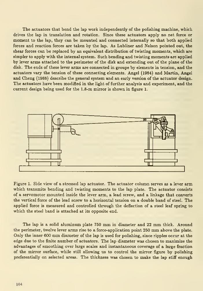
The actuators that bend the lap work independently of the polishing machine, which
drives the lap in translation and rotation. Since these actuators apply no net force or
moment to the lap, they can be mounted and connected internally so that both applied
forces and reaction forces are taken by the lap. As Lubliner and Nelson pointed out, the
shear forces can be replaced by an equivalent distribution of twisting moments, which are
simpler to apply with the internal system. Such bending and twisting moments are applied
by lever arms attached to the perimeter of the disk and extending out of the plajie of the
disk. The ends of these lever arms are connected in groups by elements in tension, and the
actuators vary the tension of these connecting elements. Angel (1984) and Martin, Angel
and Cheng (1988) describe the general system, and an early version of the actuator design.
The actuators have been modified in the light of further ajialysis and experiment, and the
current design being used for the 1.8-m mirror is shown in figure 1.
Figure 1. Side view of a stressed lap actuator. The actuator column serves as a lever armwhich transmits bending and twisting moments to the lap plate. The actuator consists
of a servomotor mounted inside the lever arm, a lead screw, and a linkage that converts
the vertical force of the lead screw to a horizontal tension on a double band of steel. Theapplied force is measured and controlled through the deflection of a steel leaf spring to
which the steel band is attached at its opposite end.
The lap is a solid aluminum plate 750 mm in diameter and 22 mm thick. Aroundthe perimeter, twelve lever arms rise to a force-application point 250 mm above the plate.
Only the inner 600 mm diameter of the lap is used for polishing, since ripples occur at the
edge due to the finite number of actuators. The lap diameter was chosen to maximize the
advantages of smoothing over large scales and instantaneous coverage of a large fraction
of the mirror surface, while still allowing us to control the mirror figure by polishing
preferentially on selected areas. The thickness was chosen to maJte the lap stiff enough
104

not to conform to errors in the mirror figure that are outside the specification. The worst
situation occurs when the lap overhangs the edge of the mirror by at most 1/4 its diameter,
in which case one can show that the lap distorts to give a maximum slope error of about
0.1 arcsec.
The stressed lap control system provides real-time, closed-loop control of the actuator
forces. These forces are related to the lap deformations through an off-line calibration
procedure that is performed as often as necessary to maintain accuracy, typically once
per month. During operation, the control computer issues conmiand signals which pass
through a slipring onto the rotating lap. These signals update the command positions for
analog servocontrol circuits controlling the actuators. The update rate is 1.8 kHz for the
entire set of twelve actuators, so the force variations are smooth and the instantaneous
forces within 0.1% of the required values.
5. Polishing machine and technique
We are polishing the 1.8-m mirror on a computer-controlled machine designed to
exploit the capabilities of the stressed lap. The position of the lap on the mirror is described
in cylindrical coordinates, with one motor controlling radial motion of the lap and a second
motor controlling rotation of the mirror. A third motor drives the lap in rotation. The
three axes are controlled independently by a 386 PC, and arbitrary polishing strokes can
be programmed. The motors produce accelerations up to 1 va/s^, allowing large variations
in removal rate as a function of position, and coverage of the entire surface in less thaji one
minute. Because of the rapid coverage of the surface, uncontrolled variations in removal
rate due to changes in abrasive concentration and properties, which typically occur on a
timescale of several minutes, are averaged over the entire surface. Such rapid coverage of
the surface is possible only because of the active control of the shape of the lap.
Our intention is to polish the mirror from start to finish with a single stressed lap, as
opposed to several laps of different diameters. In order to develop techniques that would
allow us to figure the mirror with this subdiameter lap, we initially polished the mirror as
a sphere using a passive lap of the same size and stiffness as the stressed lap. This exercise
also gave us the opportunity to solve the problems of mirror support and thermal control
without the added complication of debugging the stressed lap.
The mirror was not generated prior to being finished as a sphere, but was lapped
with loose abrasives from the spin-cast paraboloid, which had local surface irregularities
of roughly Imm and overall astigmatism of about 50 /xm. The 1/3-diameter lap has little
automatic tendency to remove large-scale errors such as astigmatism; these errors were
removed explicitly by varying the dwell time ajid rotation rate of the lap as a function
of position on the mirror. Astigmatism was removed by varying the mirror rotation rate
through each rotation so that dwell time increased in proportion to desired removal.
The final figure achieved with the mirror as a sphere meets the specification described
in Section 2, as shown in figure 2.
105

CO
0.1
0.01
1 1—I—I I I
_1 I I L_l_ J I I II I I
10separation (cm)
100
Figure 2. Surface error as a function of spatial scale on the 1.8-m mirror as a sphere. Thestraight line shows the surface error corresponding to the atmospheric wavefront distortion
for 1/8-ajcsec seeing, and the curve includes an allowance for small-scale errors that scatter
a small fraction of the light.
6. Calibration and testing of the stressed lap
The theory of plate bending establishes that we can produce very nearly the correct
shape changes in the stressed lap with the distribution of edge moments that we apply.
This was confirmed independently through finite-element analysis performed by Walter
Siegmund. The theory caji be used to obtain the forces required to bend the lap into the
proper shape as a function of its position and orientation, but the accuracy of this predic-
tion would be limited by our knowledge of the plate properties, tolerances in machining
and assembly, and accuracy of the force measurements. Instead, we use plate bending
theory only to design the lap, and determine force values empirically. Our only measure
of actuator force is the displacement of the leaf spring shown in figure 1, which is the
feedback signal for the actuator's servocontroUer. We have made no attempt to calibrate
this in terms of absolute force. We simply determiine the feedback signals required to give
the correct lap deformations.
We calibrate and test the lap by placing it on a metrology table consisting of three
hard-point supports ajid an array of 32 spring-loaded displacement transducers located on
a square grid that covers the 600-mm diameter working surface. The lap deformations are
106
computed as a function of the offset r from mirror center to lap center, and orientation
with respect to the direction to the mirror center. We choose a reference set of actuator
feedback signals to correspond to the symmetric shape required for r = 0. These values
are fairly arbitrary as the pitch will take on the correct absolute shape for one position and
orientation. The 32 displacements are read for these reference signals; all shape changes
and all other signals are measured with respect to these reference values.
For a number of positions (r, 0) , the actuator signals are varied to minimize the sumover the 32 sensors of the squared difference between measured and ideal displacement
(Angel 1984). We achieve an rms error of 3 ^m or better over the entire range of r out
to 750 mm, the maximum lap excursion. We need resolution of about 0.5 mm in r and
4 axcmin in 6 to determine actuator signals to the required accuracy. The signals vary
smoothly with r and 0, however, so we store them as smaller arrays of coarsely gridded
values, and compute derivatives as finite differences between adjacent values. The control
computer uses these arrays, with resolution of 25 mm in r and 1.4° in 0, along with the
encoder readings for r and 0, to interpolate actuator signals which are sent to the lap.
Since this computation is done in real time, only a simple linear interpolation is possible.
We can use a higher-order interpolation to go from the signals determined by calibration
to the coarse tables used by the control computer, so a much smaller number of points,
typically around 100, need to be used for the calibration.
We believe that the accuracy of 3 /Lim rms achieved during calibration is adequate
to polish the mirror to its final figure. Currently the accuracy achieved during operation
is limited to a value several times worse because of mechanical hysteresis in the system.
Friction in the bearing located at the connection between the tension band and the leaf
spring produces a bending moment that is not measured by the leaf spring's deflection and
which exhibits hysteresis through the cycle of forces. This problem does not seem to have
limited our ability to polish the mirror up to the present time, but we expect that it would
eventually limit the accuracy of the mirror figure. It will be largely eliminated in a future
implementation which replaces this bearing with a flexure pivot.
7. Progress with the f/1 asphere
Following completion of the sphere, the mirror was generated as a paraboloid using the
Large Optical Generator (Shannon and Parks 1984) at the University of Arizona Optical
Sciences Center. The generated surface was accurate to 4 /xm rms and 20 ^m peak-to-
valley, with subsurface damage extending only 30 /xm deep. It was therefore possible
to start polishing with pitch directly, without going through the usual process of loose-
abrasive grinding with a sequence of grit sizes. The lap has removed material from the high
zones left by the generator, as expected. As we write this paper the surface has not been
lowered enough to meet the lowest zones left by the generator; about 80% of the surface
now has a polished shine. The polished surface is extremely smooth, indicating that the
lap is fitting the aspheric surface adequately. As long as the lap produces a surface that is
107
smooth on small scales, we can control the overall mirror figure by varying the polishing
strokes.
8. Future polishing of Isirger primaries and other aspherics
We are currently building a 1.2-m diameter stressed lap that will be used to polish a
3.5-m f/1.5 paraboloid starting in mid-1990. Laps of 2-2.5 m will be built for the larger
primaries of the MMT upgrade project (6.5 m f/1.25) and the Columbus and Magellan
projects. These will use the same concept as the stressed lap for the 1.8-m mirror, with
modifications to the actuators and force-measuring devices based on our experience with
the first lap.
The stressed lap and polishing machine currently being used on the 1.8-m mirror
will eventually be used to polish the large wide-field secondary mirrors for the 6.5- and
8-m primaries. These secondaries are convex hyperboloids roughly 2 m in diameter, with
asphericity comparable to that of the 1.8-m primary. The stressed lap does not care
whether the surface is concave or convex, or precisely what shape changes are required,
as long as they can be represented accurately as a sum of the three lowest-order bending
modes. For the conic sections of revolution used for all classical telescope designs, a
relatively large stressed lap can be used.
For off-axis conic sections and general aspherics, one can always represent any suffi-
ciently small sub-aperture in terms of the low-order distortions that the stressed lap can
produce. For a severe aspheric, as one increases the lap size, the higher-order distortions
eventually become important and the lap will not fit the mirror adequately. This limiting
lap size, however, will be many times greater than that of a passive lap which cannot
accommodate any change of shape beyond the tolerance in fit.
9. Acknowledgements
The development of the stressed lap has been possible only through the combined
effort of a number of scientists, engineers and programmers. We particularly acknowledge
the contributions of Dave Anderson, Bob Nagel, Dick Young, and the Steward Observatory
technical division.
References
Angel, J. R. P. 1984, Proc. lAU Colloquium 79: Very Large Telescopes, Their Instrumen-
tation and Programs, ed. M.-H. Ulrich and K. Kjar, 11.
Angel, J. R. P. 1987 in Identification, Optimization, and Protection of Optical Telescope
Sites, ed. R. L. Mills et al., 167.
Angel, J. R. P., Hill, J. M., Martin, H. M. and Strittmatter, P. A. 1989, Astrophysics and
Space Science, 160, 55.
Brown, D. S. 1983, Proc. SPIE, 399, 12.
Lubliner, J. and Nelson, J. E. 1980, Applied Optics, 19, 2341.
108

Martin, H. M., Angel, J. R. P. and Cheng, A. Y. S. 1988, Proc. ESO Conference on Very
Large Telescopes and their Instrumentation (Garching: ESO), 353.
Shannon, R. R. and Parks, R. E., Proc. SPIE, 444, 271.
TatajTski, V. I. 1961, Wave Propogation in a Turbulent Medium (New York: McGraw-Hill).
DISCUSSION
Macchetto : Wouldn't you end up with different micro-roughness in different places with the stressed
lap technique?
Angel: We expect that with large laps matched to the radius of curvature micro-roughness will be
very small. This technique may be the best hope for generating optics with smooth surfaces.
109
Large Telescope O-IR Astronomy from the ground
N. Woolf
Steward Observatory, University of Arizona
Introduction
What you would like me to say, is that large telescope diffraction limited observations can't
be done from the ground. Failing that, you would like me to say it CAN be done from the
ground. I bring you the worst message of all. We don't know whether it can be done fromthe ground. Or rather, that we suspect that some things can be done from the ground, andsome can not be done from the ground, and it will take a great deal, of observational andexperimental work to find where the boundary lies.
There are of course some things that will never be done from the ground, because the
atmosphere absorbs too much. Thus the region from 3000 to 912A is totally reserved for
space observations. Similarly, telescopes on the ground will always have some surfaces with
noticeably emissivity at ambient temperature. There will thus be an IR background that
limits the sensitivity of equipment at wavelengths beyond 3 or 5 microns. And at somewavelengths airglow will make space the preferred location because of its reduced sky
brightness. But in between lies the bulk of the region where astronomy has cut its teeth,
and where we know most. That is the obvious region to advance with diffraction limited
imaging by large telescopes.
Adaptive optics
The process for correcting images to diffraction limit in real time is called adaptive optics.
There is the use of some kind of flexible surface to correct for wavefront errors put in bythe atmosphere. There is the sensing and measuring of those errors to know how muchto correct.
Because the refractive index of air is fairly constant across the visible and IR region, the
wavefront error information sensed from one wavelength region can be used to correct at
some other region. Because the accuracy of correction needed is reduced when the
wavelength is longer, it is much easier to correct an infrared image in real time than anoptical image in real time, and the image will stay corrected for a longer time, and becorrected over a wider field. The time and field diameter increase somewhat faster than
the wavelength, so that there are somewhat more diffraction limited pbcels in the
correctable field at longer wavelengths.
110
The length of time for which the image stays corrected, is the length of time for which the
rms wavefront error stays within our diffraction limited tolerance of 1/10 to 1/20 wave.
Because this time is very short in the visible, the correction must be carried out on a star
with a substantial photon flux, somewhere between 8th. and 11th. magnitude. However
there are experiments underway, using the telescope to project an artificial star by reflecting
Sodium D lines off the upper atmosphere, and correcting on the image of that. If the
process is successful, diffraction limited imaging will be available anywhere in the sky.
The next problem is that the wavefront errors arise at various layers throughout the
atmosphere, while the correction is currently applied at a single surface which can at most
be conjugate with a single layer of the atmosphere. As a result, the correction is only
appropriate for a small area, the isoplanatic patch, around the light source and in
consequence only a limited area of sky is corrected to diffraction limit. There are however
possibilities of having more than one corrective surface, and so widening the region of sky.
The expected final result is that visual images will be corrected across a patch of sky some2" to at most 20" in the visible, while at 10 microns, the corrected area will be some minutes
of arc in size. The correction at longer wavelengths will be better and much easier, giving
a longer coherence time, a larger isoplanatic patch and being possible on a fainter star if
the initial seeing is superior. Adaptive optics is a way of improving the best sites, it is
relatively poor at coping with the inferior ones.
Because a patch of Sodium light reflected from the upper atmosphere will show a parallax,
the size of telescope is limited for having the source in the same isoplanatic patch for all
parts of a large primary mirror. Conquering this problem will need a complex solution, but
it is not in principal impossible.
What can adaptive optics achieve?
The first thing we have to realize is that the size of the isoplanatic patch is independent of
the telescope size. In consequence, the number of diffraction limited patches that can be
placed in a single isoplanatic patch increases as the primary mirror area increases. Even
a 2" patch can contain 2000x2000 pixels, if the pbcel is 0.001" across. However this
corresponds to a telescope primary 100m across. If we assume a standard ratio for the cost
of ground and space facilities of 500:1, and cost being proportional to mirror area then such
a ground telescope would cost about the same as a 4m telescope in space. One difference
is that, astonishingly, our technology is currently more geared to dealing with the problems
of space.
If we had such a giant telescope, with such spectacular angular resolution, what would we
do with it? There are three obvious areas of research. The first is studies of intrinsically
bright objects, such as the surfaces of stars, the second is a study of the regions close to
stars for objects related to those stars. The third is to say that the universe is similar in all
directions, and so the regions close to the direction to stars is just like any other region, and
one can study cosmology in them, and very well too, IF the telescope reaches sky
background in the area we are observing. Thus the dark sky point source faintness limit
of a 100m diffraction limited telescope is under those circumstances 7 magnitudes fainter
than the limit of a 4m telescope, and 5m fainter than the limit of a 10m telescope.
Ill

The background limit of telescopes with adaptive optics
If we observe near a star, using the star's light for adaptive optics, there is a concern that
the scattered light from the star will exceed sky background. On the other hand if there
is an artificial star made with sodium light, the sodium emission is easily filtered away. But
we currently better understand how to use the real star as a source for adaptive optics.
Thus it is appropriate to consider the scattered background around a star. For problems
of planetary searches, from any platform, the problem of scattered light is a crucial one.
Ivan King (1971) published the profile of a star image, and it was later shown by two
different groups that the profile consists of two parts, an inner region which is on the
ground dominated by seeing, and an outer region which is called the aureole.
Following this talk, and at this meeting, a consensus developed that the aureole is the result
of the residual polishing imperfections on the mirror. On the small scale, these are referred
to as "orange peel" and "dog biscuit". The larger the scale of the structure, the closer in is
the scattered light, thus orange peel and dog biscuit affect the outer parts of the aureole
from about 10" out, ripple because of the use of small tools affects the area further in.
There are possibilities of substantially reducing the ripple by (1) polishing aspheric surfaces
with a stressed lap, (2) avoiding segmentation and controlling mirror shape at the support
points, and (3) avoiding any obscuration in the beam by use of off-axis optics. Thereduction of orange peel and dog biscuit seem likely to require some form of super
polishing.
Some improvement in both large and small scale correction will be needed if we are to
study cosmology using the areas of the sky close to stars. With current mirrors, the aureole
at about 4500A is fainter than the star by about 10 magnitudes per square arc second at a
radial distance of 3", and at 9" it is about 12.5 magnitudes fainter. The light at every part
of the aureole is likely to be reduced by the square of the wavelength. You can see
therefore, that at least in the visual there will be a very delicate question whether
sufficiently faint stars can be used for adaptive optics that the sky background light will
dominate at the outer part of the isoplanatic patch. The critical question is whether the
large ground telescope concept is boxed in between wavelengths sufficiently short that the
zodiacal light dominates airglow, and yet at the same time that the night sky brightness
dominates inside the isoplanatic patch.
Forms of Large Telescope
Both on the ground, and in space there is considerable confusion about the relative role of
large telescopes and interferometers. I do NOT regard them as interchangeable, at least
at wavelengths below a few mm. where one is in the photon-noise dominated regime.
Equally, I regard them both as extremely important. The interferometer clearly has a better
potential for highest angular resolution, and the single aperture is, for currently imaginable
costs and associated aperture sizes, the leader in point source sensitivity.
The difference between a radio and an optical interferometer arises because the noise at
radio wavelengths is dominated by wave-noise, or if you will by the statistics of the bunching
of bosons, whereas in the O-IR region, the detection events are far fewer and are
dominated by individual particle statistics. In consequence amplifiers are able to be
112

relatively noise free at radio wavelengths and are very noisy at optical wavelengths, with
even a perfect amplifier producing one noise event per unit time per unit bandwidth. (I amindebted to Dr. B. Burke for directing me to this conclusion). Thus the optical
interferometer is forced to detect at the place where the light is brought together, while at
radio wavelengths it is possible to amplify a signal, split this up, and get independent
interference between beams. The problem shows up in the mapping mode, but need not
show up in the spectroscopic observation of a single point source once its position has been
determined.
Thus a single point source can be tracked and if the interferometer aperture is kept phased
by variable delay lines (i.e. one sits on top of the bright fringe), and if perfect beamsplitters
are assumed the device will reject the incoherent light of the background and so allow the
same signal/noise ratio that would be obtained for the same area in the form of a single
dish. ( This was pointed out to me by Dr. Angel). Unfortunately, for this configuration the
light from many other areas of the sky is suppressed by interference because the
interferometer impresses fringes onto the plane of the sky.
If however one instead attempts to map an area of sky, then one finds the light spread
angularly into a pattern where a substantial fraction of the energy appears in low-surface
brightness side-lobes (see for example the patterns shown by Meinel, Meinel and Woolf
1983). There is then a loss of signal/noise ratio if there is a sky background that is
appreciable compared with the signal. Because of the background, the light in these low
level frringes can be detected with at most an extremely low signal/noise ratio, and in
consequence it hardly helps in the total observation. The problem appears to be reduced
by, (1) using fewer, larger interferometer elements and moving them around to synthesize
an aperture, with three elements being a probable optimum, or (2) having the
interferometer spacings redundant, and in the extreme variant of this, in having all elements
co-linear. Either of these solutions places considerable emphasis on aperture rotation
synthesis.
It is interesting to consider three concepts intermediate between a telescope and an
interferometer to try to balance the astronomical advantages of a single large instrument.
In the NNTT 4-square concept (Angel and Woolf 1986), four close spaced large apertures
were used to get somewhat higher angular resolution than for a single dish of the same
area, and with a modest loss of point-source sensitivity in the sky-viewing mode. Theversatile array concept (Woolf, Angel and McCarthy 1983) uses a similar 4 apertures in a
linear non-redundant array, in which there was a greater loss of point sensitivity, though
reduced by the co-linearity of the elements, and a much greater gain in angular resolution.
The third (Angel, Woolf and Epps 1982) was the use of a non-circular aperture, a highly
elongated one, with the use of rotation synthesis and tomographic image reconstruction.
This last seems to me to be worth far more consideration for large space and lunar
telescopes as well as for giant telescopes on the ground. It has the full point source
sensitivity of the aperture for spectroscopic observations, without any special efforts beyond
those normal for adaptive optics on the ground, or alignment and phasing in space.
Further, it is possible to map in various ways that allows the data to be analyzed either for
optimum point source sensitivity or for maximum angular resolution
113
Conclusions
There are no very simple conclusions. The balance of opportunities and costs of doing
astronomy from the ground and space is a most difficult topic, even without the
uncertainties that started this paper. I believe it is entirely appropriate to put substantial
effort into concept development, and particularly into cost reduction for all schemes for
giant astronomical facilities. Every dollar spent in this phase can pay off hundredfold in
our eventual decision. It is in this phase that the normal committee type of compromise
is least helpful. We need to discover the optimum, regardless of individual feelings.
Equally I feel that we cannot afford to overbalance our efforts either towards large
telescope structures or towards interferometry. There will indeed be a time when we have
to set a priority, and all pull together for a single device, and maybe even for a single
platform. Earth, orbit or Moon. That time is not yet here. And equally, we are all
responsible that EVERY concept is the very best one of its kind possible. We are here to
get the best for astronomy, not to push anyone's pet scheme.
References
Angel J.R.P. and Woolf N.J. 1986 Ap.J. 301.478
Angel J.R.P. Woolf N.J. and Epps H.W. 1982 Proc. S.P.I.E. 332.134
King I. 1971 Pub. Astr. Soc. Pacific,83,199
Meinel A., Meinel M. and Woolf N. 1983, App.Optics & Opt.Eng. 9,150
Woolf N.J., Angel J.R.P. and McCarthy D.W.Jr. 1983, Proc. S.P.I.E. 444, 78
114
Session 4
Current Proposals and Studies
115


Considerations for a
Next Generation UV/Optical
Space Telescope
During the past 25 years, a remarkable scientific
revolution has occurred in astrophysics as a re-
sult of convergence on two advancing fronts.
First, instruments and telescopes have been de-
veloped to make sensitive measurements through-
out the entire electromagnetic spectrum. Sec-
ondly, access to space has permitted observa-
tions above the obscuring and distorting "dirty
window" of our atmosphere. Beginning around
the middle of the next decade, a third major path
— the availability of the permanently manned
Space Station Freedom— will join with the ear-
lier two capabilities, to not only continue this
M.E. Nein and S.H. Morgan
NASA - George C. Marshall
Space Flight Center
revolution, but to accelerate the quest for an-
swers about the universe that have puzzled man-
kind for centuries. Beyond Earth-orbit, NASA is
actively studying the possibility of a return to the
Moon, which would provide a valuable platform
for astrophysics observations during the next
century.
The promise offered by space observatories will
be dramatically illustrated when four observa-
tories, the Hubble Space Telescope (HST),
Gamma Ray Observatory (GRO), Advanced X-
Ray Astrophysics Facility (AXAF), and Space
Figure 1 . NASA's Great Observatories
117
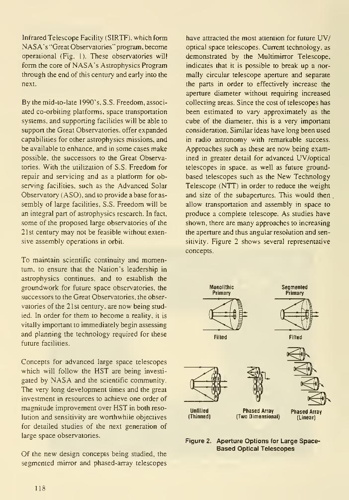
Infrared Telescope Facility (SIRTF), which form
NASA's "Great Observatories" program, become
operational (Fig. 1). These observatories will
form the core of NASA's Astrophysics Program
through the end of this century and early into the
next.
By the mid-to-late 1990's, S.S. Freedom, associ-
ated co-orbiting platforms, space transportation
systems, and supporting facilities will be able to
support the Great Observatories, offer expanded
capabilities for other astrophysics missions, and
be available to enhance, and in some cases make
possible, the successors to the Great Observa-
tories. With the utilization of S.S. Freedom for
repair and servicing and as a platform for ob-
serving facilities, such as the Advanced Solar
Observatory (ASO), and to provide a base for as-
sembly of large facilities, S.S. Freedom will be
an integral part of astrophysics research. In fact,
some of the proposed large observatories of the
21st century may not be feasible without exten-
sive assembly operations in orbit.
To maintain scientific continuity and momen-
tum, to ensure that the Nation's leadership in
astrophysics continues, and to establish the
groundwork for future space observatories, the
successors to the Great Observatories, the obser-
vatories of the 21st century, are now being stud-
ied. In order for them to become a reality, it is
vitally important to immediately begin assessing
and planning the technology required for these
future facilities.
Concepts for advanced large space telescopes
which will follow the HST are being investi-
gated by NASA and the scientific community.
The very long development times and the great
investment in resources to achieve one order of
magnitude improvement over HST in both reso-
lution and sensitivity are worthwhile objectives
for detailed studies of the next generation of
large space observatories.
Of the new design concepts being studied, the
segmented mirror and phased-array telescopes
have attracted the most attention for future UV/optical space telescopes. Current technology, as
demonstrated by the Multimirror Telescope,
indicates that it is possible to break up a nor-
mally circular telescope aperture and separate
the parts in order to effectively increase the
aperture diameter without requiring increased
collecting areas. Since the cost of telescopes has
been estimated to vary approximately as the
cube of the diameter, this is a very important
consideration. Similar ideas have long been used
in radio astronomy with remarkable success.
Approaches such as these are now being exam-
ined in greater detail for advanced UV/optical
telescopes in space, as well as future ground-
based telescopes such as the New Technology
Telescope (NTT) in order to reduce the weight
and size of the subapertures. This would then
allow transportation and assembly in space to
produce a complete telescope. As studies have
shown, there are many approaches to increasing
the aperture and thus angular resolution and sen-
sitivity. Figure 2 shows several representative
concepts.
Monolithic
Primary
SegmentedPrimary
Filled Filled
^^̂
Unfilled
(Thinned)
Phased Array
(Two Dimensional)Phased Array
(Linear)
Figure 2. Aperture Options for Large Space-Based Optical Telescopes
118

In order to "thin" the aperture, several major
considerations must be addressed to ensure that
the optical performance remains acceptable. The
modulation transfer function, as a measure of the
optical performance, must not become zero any-
where except at the highest spatial frequency
(corresponding to the diffraction limit of the
circumscribed (full) aperture diameter). Other-
wise, information at some spatial frequencies
will be lost. The practical consequences of this
are reflected in careful selection requirements
for subaperture spacing and location. Experi-
mental results, reported elsewhere, seem to indi-
cate that advantageous placement of the subaper-
ture can be accomplished.
Although optical performance considerations
play a major role in the selection of a telescope
concept, other important aspects also become
major trade criteria in the design of advanced
space telescopes. Some of these criteria are listed
in Figure 3, where various telescope concepts
are compared. It is obvious that the traditional
contiguous-filled circular aperture concept has
excellent optical performance, allows testing of
the complete optical train on the ground (al-
though necessarily under degraded conditions
because of the g-loading), avoids the complexi-
ties of orbital assembly, and does not require
rotation of the telescope to construct an image.
Unfortunately, the extreme weight and volume
associated with this approach could exceed the
transportation-to-orbit capability of projected
future launch vehicles, unless extreme attention
is paid to superlight-weighting of the mirror and
telescope structure and the spacecraft compo-
nents. The latter, however, normally has a high
price tag associated with it. For example, a 10-m
Advantages Disadvantages
Advanced Technology
Development Auxilliary
Systems
Contiguous
Filled Circular
Aperture
SegmentedFilled
Aperture
Mills
Cross
SegmentedDiluted
Aperture
Traditional Concept
Excellent PSF
Excellent Spatial
Frequency Coverage
On-Ground Testing
No Rotation
No On-Orbit Assembly
Optically Traditional
Concept
Excellent PSF
Excellent Spatial
Frequency Coverage
No Rotation
Light Weigtit
Transportation (Ground
& Space)
High Resolution
Growth Capabilty
On-Ground Testing
Space Transportation
Moderate Optical Path
Compensation
Moderate Alignment
Growth (Restncted to
Initial Aperture
No Rotation
Limited Resolution
No Modularization
Extreme Weight & Volume
Transportation (Ground &Space)
Heavy Launch Vehicle
• Off Axis Aspheres
• Complex Assembly• Complex Alignment
• Limited Sensitivity
• Number of Reflections
• Field of View
• Image Reconstruction
• Beam Alignment
• Rotation
• Limited Sensitivity
• Moderate Spatial Freq.
Coverage
• Ofl-Axis Aspheres
• No Ground Testing as a
Completed Telescope
• Size. Inertia
• No Modulanzation
• Difficult Assembly
Structural Stability
Launch Vehicle
Transportation to Oper.
(GEO?) Orbit
Mirror/Telescope Assembly
Structural Stability
Precision/Large Number
Segment Fabrication
Precision Alignment &Control Actuators
Optical Coatings
• Optical/Mechanical Phasing
• Stable Structures
• Optical Coatings
• Fine Guidance Telescope
Coalignment
• Precision Alignment
Actuators
• Large Stable. Adj. Structures
• Large Off-Axis Mirrors
• Orbital Assembly
• Transportation to Oper.
Ortjit
PSF = Point Spread Function
Figure 3. Typical Trade Considerations for Telescope Concepts
119

®HST .. ,
(2 4m) Monolith^
' (lO-m)
Monolithic
Approaches
1000
100
£ 10
1 .
oLDR(Ref)
O4-MeterGround(Ref)
VLSI(8-m) LDR
(20-m)1
SegmentedApproaches
VLSI
COSMIC-4
HST COSMIC-1
Diffraction-Limited
Full Aperture (6300 A)
OOOOSCOSMIC-1(14x2-m)
COSMIC-4(28x2m)x(28x2m)
@ 1000m
.JTRIOSSAMSI
I
Interferometer Approaches
HST

Table I. Performance Comparison of UV/Optical Telescopes
Telescope
System

and robotics, initial alignment, and long-term
maintenance have only recently received atten-
tion. Early analysis shows that transportation to
an orbital altitude of 300 nmi with subsequent
assembly requires launch capabilities of the or-
der of 50 tons for a thinned primary mirror-type
telescope with 10-fold increase in resolution over
the HST. This capability may be available early
in the 21st century. However, a high Earth orbit,
especially a geosynchronous orbit (GEO), would
be better for the observatory, since both gravity
gradient and aerodynamic torques are minimized.
For the large telescopes under consideration,
these torques are the major environmental dis-
turbances and are the primary drivers of momen-
tum management and control system design in
low Earth orbit.
Additional considerations for operating large
observatories in high Earth orbit, or preferably
GEO, are shown in Table II. Thus it becomes
obvious that orbit-to-orbit transportation will be
one of the major considerations in the develop-
ment of future large observatories, affecting every
aspect of the design. Since there are currently no
indications in NASA's future mission models of
an Orbital Transfer Vehicle (OTV) with the ca-
pability to transport 50 tons of payload to GEO,telescope designers must consider assembly of
telescope modules at high altitude orbit loca-
tions either through robotics, by astronauts, or
both. Alternatively, telescopes must be designed
which can be accommodated by projected launch
vehicles, even at the expense of some scientific
capabilities. To operate these observatories at
more accessible orbits will entail the problems
highlighted in Figure 6. It is clear that assembly
by robotics and/or man in GEO without the
presence of a large operational base, such as a
temporarily or permanently manned GEO sta-
tion, will further complicate the design of these
telescopes.
In order to better understand the key technology
issues which will have to be resolved before
serious design approaches can be advanced,
several different generic telescope system con-
cepts are now being analyzed by NASA. As
Table II. Orbit Considerations for Future Astronomical Observatories
LEO

Dimensional Stability
• Mirror Figure & Surface '\ -J• Segment Alignment, Element Phasing I s/• Material Stability / V• Thermal Structural Dynamics• Subsystem Interaction
• Pointing & Stability Control of LowFrequency Structures
Orbital Requirements
• Transportation to Orbit \
•Assembly / ?• Initial Alignment & Maintenance of Alignment /
• Orbit to Orbit Transfer r ?
• Operations \
• Maintenance & Repair ?
o
Figure 6. Key Enabling Tectinologies for Advanced Telescopes
pointed out by the Space Science Board's Task
Group on Astronomy and Astrophysics in its
study of major directions for space sciences
during the 1995-2015 time period, astronomers
will probably pursue two different approaches:
( 1 ) high resolution through interferometry, which
means a large baseline between sensors, and (2)
high "throughput" for imaging faint objects. This
requires large 8- to 16-m diameter mirrors.
In concert with these recommendations. MSFChas conducted studies of two representative
advanced telescope configurations to further
assess a range of key technical problems inher-
ent in both interferometric-type telescopes and
large contiguous primary mirror telescopes.
The interferometric telescope concept selected
for technology investigations is a type represen-
tative of the one-dimensional Coherent Optical
System of Modular Imaging Collectors (COS-
MIC) that was previously studied. The particular
arrangement selected is known as a "Golay 9"
array. This concept is optimum from the stand-
point of providing an autocorrelation function of
maximum compacmess. The two-dimensional
array of nine afocal telescopes arranged in a
nonredundant pattern is shown in Figure 7. This
concept has the advantages of being relatively
compact, not requiring rotation to form an im-
age, and allowing later expansion of the baseline
by the addition of more telescopes that would
feed the same beam combiner. However, there
123

Figure 7. Two-Dimensional Coherent Array Telescope
are also disadvantages associated with these types
of systems. They suffer from low UV throughput
due to the eight or more reflections needed to
bring the collected light to focus. In addition, the
useful field of view (FOV) is very narrow, only a
few tens of arcseconds (Fig. 8). This may not be
too critical, however, since even a 10-microrad
FOV will require a detector array with 1 million
resolution elements (for 10-nanorad telescope
resolution). Other design benefits must also be
considered, such as construction and checkout of
the individual telescopes on the ground and trans-
portation to and assembly in orbit. Furthermore,
considerably less cross-sectional area is exposed
to the micrometeoroid and space debris flux
compared to large, contiguous aperture systems.
The probability of micrometeoroid impact with
the mirror surfaces is therefore reduced, allow-
ing smaller light shields made from rigid mate-
rial (a micrometeoroid bumper). This enhances
the ability to control straylight increases during
the telescope lifetime.
In order to investigate the technology require-
ments for a partially filled primary mirror tele-
scope, the two-dimensional configuration shown
in Figure 9 was selected. In this concept, the pri-
mary mirror consists of 1 8 off-axis segments of a
single parent primary mirror feeding light to a
common secondary mirror and thence to a focal
plane behind the primary in a Cassegrain or
Ritchey-Chretien arrangement. The nonredun-
dant, two-dimensional pattern provides the wid-
est two-dimensional aperture separation that
avoids zeros in the optical transfer function. The
initial dilute aperture configuration requires some
degree of image processing to obtain diffraction
hmited imagery. This concept, an unfilled aper-
ture with a common secondary mirror, has a
large FOV (recognizing that detector arrays may
not be available to fill the focal plane). It allows
a later increase of the sensitivity by the addition
of segments to the primary and has a minimumnumber of reflections — thus a high UV through-
put. The major disadvantage of this approach is
124

1 2
Semi-Field Angle (Arc-Min)
Figure 8. Field of View for Various Aperture
Configurations
that a very large outer structure is required to
place the secondary mirror at the proper distance
from the pnmary. The large dimensions pose
problems, not only in control, but also in launch
and assembly of the telescope modules. The
system will only function as a complete tele-
scope for the first time when the modules are
assembled in space. Because of the large dimen-
sions of the lightweight support structure, com-
plete assembly and checkout on Earth is proba-
bly impossible or meaningless, at least from the
standpoint of verifying optical performance.
Although studies of various telescope systems
and the associated problems of orbital assembly
of the telescopes are in progress, preliminary
technology assessments have been completed
and criticality and technology-readiness judg-
ments have been made in order to scope the need
and specific objectives of additional studies.
Erectable Secondary
Mirror Assy
Compression Struts
Light Shield andBaffle System
Tension
Wire Ass'y
M'mor Integrating
Structure
Chordal Rib
Radial ArmBrace Strut
Fine Guidance andInstrument Module
Workshop Module(Optional)
Mirror SegmentShown in Final
Position
Spacecraft Attitude
Stabilization Module Incl.
Command, Control Power,
Survival Aids
Orbiter Bay Outline
Shovm by Shaded Area
Docking Adapter
OTV ModuleOrbiter Cargo
Bay Diameter
Figure 9. Thinned Primary Mirror with Common Secondary Mirror Telescope
125
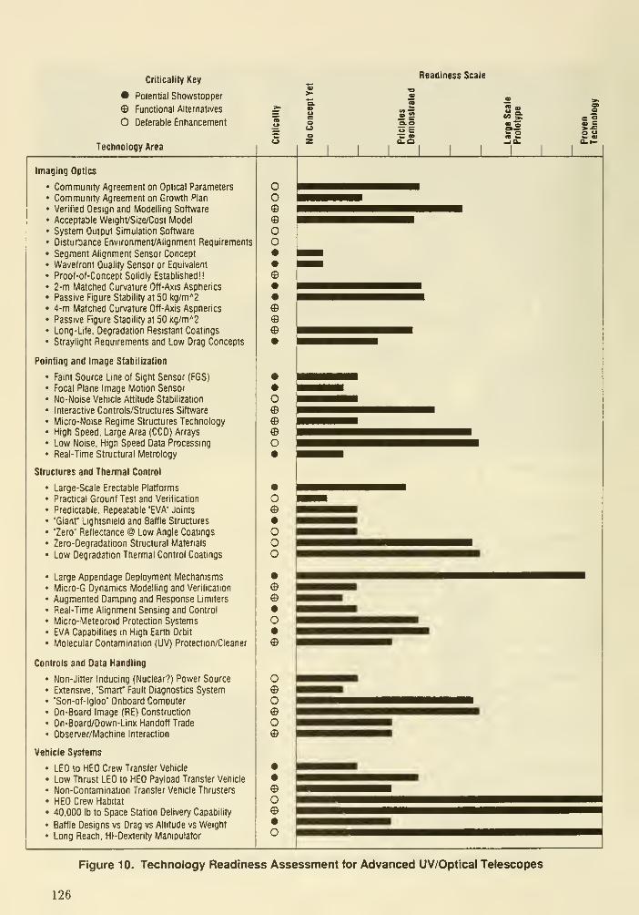
Criticality Key
• Potential Showstopper
© Functional Alternatives
O Deferable Entiancennent
Technology Area
Readiness Scale
uE
Imaging Optics
Community Agreement on Optical Parameters
Community Agreement on Growth Plan
Verified Design and Modelling Software
Acceptable Weight/Size/Cost Model
System Output Simulation Software
Disturbance Environment/Alignment Requirements
Segment Alignment Sensor Concept
Wavefront Quality Sensor or Equivalent
Proof-of-Concept Solidly Established!!
2-m Matched Curvature Off-Axis Aspherics
Passive Figure Stability at 50 kg/m"2
4-m Matched Curvature Off-Axis Aspherics
Passive Figure Stability at 50 kg/m'^2
Long-Life. Degradation Resistant Coatings
Straylight Requirements and Low Drag Concepts
Pointing and Image Stabilization
• Faint Source Line of Sight Sensor (FGS)
• Focal Plane Image Motion Sensor
• No-Noise Vehicle Attitude Stabilization
• Interactive Controls/Structures Siftware
• Micro-Noise Regime Structures Technology• High Speed, Large Area (CCD) Arrays
• Low Noise. High Speed Data Processing
• Real-Time Structural Metrology
Structures and Thermal Control
Large-scale Erectable Platforms
Practical Grounf Test and Verification
Predictable. Repeatable "EVA" Joints
"Giant" Lightshield and Baffle Structures
"Zero" Reflectance @ Low Angle Coatings
Zero-Oegradatioon Structural Materials
Low Degradation Thermal Control Coatings
Large Appendage Deployment Mechanisms
Micro-G Dynamics Modelling and Verification
Augmented Damping and Response Limiters
Real-Time Alignment Sensing and Control
Micro-Meteoroid Protection Systems
EVA Capabilities in High Earth Orbit
Molecular Contamination (UV) Protection/Cleaner
Controls and Data Handling
• Non-Jitler Inducing (Nuclear?) Power Source
• Extensive. "Smart" Fault Diagnostics System• "Son-of-lgloo" Onboard Computer• On-Board Image (RE) Construction
• On-Board/Down-Llnl< Handoff Trade
• Observer/Machine Interaction
Vehicle Systems
• LEO to HEO Crew Transfer Vehicle
• Low Thrust LEO to HEO Payload Transfer Vehicle
• Non-Contamination Transfer Vehicle Thrusters
• HEO Crew Habitat
• 40.000 lb to Space Station Delivery Capability
• Baffle Designs vs Drag vs Altitude vs Weight
• Long Reach, Hl-Dextenty Manipulator
OO
OO•
©
©©
o
o
o©•ooo
o
o©o©o©
©o©
o
Figure 10. Technology Readiness Assessment for Advanced UV/Optlcal Telescopes
126

These technology assessments are summarized
in Figure 10.
Although the successors to NASA's Great Ob-
servatories will probably not be operational until
early in the 21st century, history has shown it
takes at least 15 to 25 years from concept to
flight of a large spacebome astronomical tele-
scope. Figure 1 1 indicates that the HST develop-
ment cycle, spanning a period of 23 years, is not
an anomaly. If one includes the precursor tech-
nology development projections for the AXAF,even at this early stage in the program, the fore-
cast is a development time of about 25 years.
From the time observational astronomy began
almost 400 years ago with the small telescope of
Galileo, to the sophisticated instruments of to-
day, this discipline is driven by technology. The
technology available for the next generation of
space telescopes cannot be predicted, based solely
on this discipline's demands. Rather, it depends
to a large degree on the requirements of the other
disciplines that use the capabilities of space.
Therefore, it must be recognized that a technol-
ogy development period of at least 5-10 years
must be allocated in advance of any serious
design efforts. Thus, it is appropriate and neces-
sary that concept studies be conducted now to
identify the key enabling technologies, not only
for the eventual development of these advanced
telescopes, but also for transportation and as-
sembly requirements (Fig. 12). These require-
ments will have a major influence on telescope

Sensitivity Resolution
Transportation/
Assembly
Modularization
Optical Configuration
Fill Factor
Field ot ViewMTF Zeros
Reflectivity/
Optical Coatings
SystemWeight
Optical/
Mechanical
Stability
Program Cost
Figure 12. Generic Design and Technology Concerns for Advanced Telescopes
designs. As a matter of fact, the very configura-
tion of the telescopes and apertures arrangement
may be determined by the transportation sys-
tems available, orbital assembly, tools, facilities,
and construction sequences which must be com-
patible with the man-machine interfaces.
NASA has recently expressed three major goals
for the Agency:
• Advance scientific knowledge of the planet
Earth, the solar system, and the universe
beyond
• Expand human presence beyond the Earth
into the solar system
• Strengthen aeronautics research and develop
technology toward promoting U.S. leader-
ship in civil and military aviation.
Consistent with the first and second goals and
now specifically directed by the President's
"New Initiative for Space Exploration" is a re-
turn to the Moon (Fig. 13). This was, in fact, a
recommendation of the National Commission
on Space.
Since the Moon has no obscuring atmosphere, it
would be an ideal platform for astronomical
Continue observations with increasing
sensitivity and angular resolution
Use the unique science opportunities afforded
by observations from lunar facilities for
increases in resolution and sensitivity if cost
effective
Plan for evolutionary development of the lunar
facilities
Figure 13. Next Century Astronomy Objectives
128

observations (Fig. 14). A stable and low gravity
environment would provide a platform for ob-
servations, such as interferometric measurements
— both at radio and visible wavelengths. For
example, the pattern of the Very Large Array
(VLA) to make long baseline interferometry
measurements in radio astronomy could be fol-
lowed to construct a "Lunar Optical VLA" (Fig.
15) as proposed by Professor Bernard F. Burke
of the Massachusetts Institute of Technology. Aset of 1-m class telescopes would be deployed
along a "Y"-shape, each arm 6 km long, with a
maximum baseline of 1 km. An angular resolu-
tion of 10 micro-arc seconds at 5000 A, a four
order ofmagnitude improvement over HST, could
be possible with this system. The placement of
other large telescopes, such as a 16- to 20-m di-
ameter UV/optical/IR system (Fig. 1 6) and other
interferometric telescopes on the near or far side
of the Moon offer interesting trade options; and
certainly will affect the design of future space
observatories, not only from the viewpoint of
transportation requirements and assembly on the
Moon by man and robots, but also from the as-
pects of modularity and commonality with orbit-
ing space telescopes.
Exciting prospects await astrophysics research
during the next 25 years. The Great Observato-
ries, observations from S.S. Freedom, and spe-
cialized space missions will evolve to the devel-
opment of space observatories with even greater
capabilities. The demands for improved perform-
ance require aggressive long-term technology
development. Moreover, these advanced obser-
vatories will no longer be guided by historical
BENEFITS
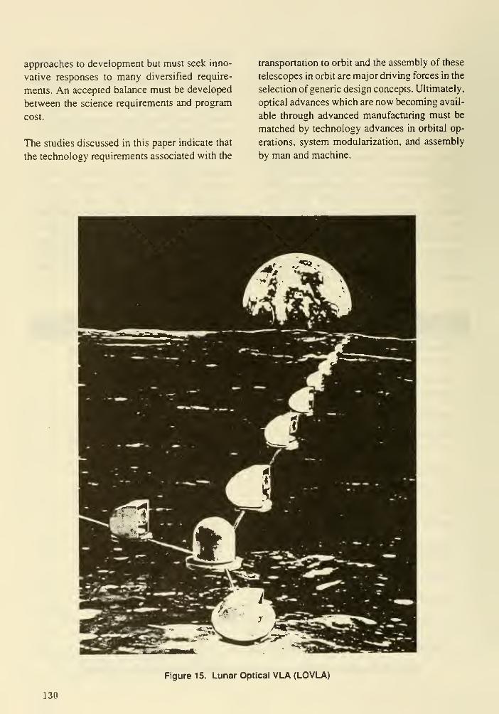
approaches to development but must seek inno-
vative responses to many diversified require-
ments. An accepted balance must be developed
between the science requirements and program
cost.
The studies discussed in this paper indicate that
the technology requirements associated with the
transportation to orbit and the assembly of these
telescopes in orbit are major driving forces in the
selection of generic design concepts. Ultimately,
optical advances which are now becoming avail-
able through advanced manufacturing must be
matched by technology advances in orbital op-
erations, system modularization, and assembly
by man and machine.
Figure 15. Lunar Optical VLA (LOVLA)
130
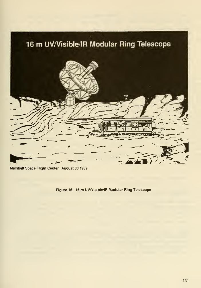
Marshall Space Flight Center August 30,1989
Figure 16. 16-m UV/Visible/IR Modular Ring Telescope
131

DISCUSSION
Bender : How bad is the debris problem at 1500 km altitude, where you can get a fully illuminated
sun synchronous orbit?
Nein : As shown in the graph below, the modelled surface area flux is a line straight above 700 km,
although there is a valley at 1300 km and a drop off past 1500 km. However the second peak occurs
at 15Q0 km. This would not be a good location from a debris point of view and also because of the
radiation environment).
1—^-^—
a
• ICltud* Iksl
>!«« \ FUb c«ultli« trm mil i<>jKt cradnd b)
(£ S^cm QamM UMfmmi b> die HaleJ
wliMM* to- K> a okjKta In Jtouir. 1987.
•n crWul laclinUon a< tO'«— iiii f« .
Ejgenhardi : Large impacts (greater than a few mm) are due to micio-meteoioids and will be a problem
in any orbit. 1500 km is a bad altitude.
Dlingworth: What is the projected capability of OTV for weight/size from LEO to HEO?
Nein : The payload capability of an OTV can range from 13-30 klb depending on assumptions made
for launch vehicle and engine. The volume available for the payload is about 15 ft diameter by 20 ft
long.
Davis: What is the assembly time for large observatories?
Nein : Assembly time for the Galaxy 9 was estimated at about 800 EVA hours by MSFC. This is
characteristic of all 10 m or larger observatories if restricted to launch by the shuttle (15' diameter
payload bay). The assembly time via EVA is prohibitive and we conclude that for some time robots
or automation are required. However, most 10 m si»e telescopes could be loaded without on orbit
assembly by the Shuttle C Block II 10m x 30 payload bay and 150 klb to LEO, or possibly the ALS.
132

IBIS: AN INTERFEROMETER-BASED IMAGING SYSTEM FOR DETECTING
EXTRASOLAR PLANETS WITH A NEXT GENERATION SPACE TELESCOPE
David J. Diner
Jet Propulsion Laboratory, California Institute of Technology
Mail stop 169-237
4800 Oak Grove Drive
Pasadena, CA 91109
(818)354-6319
1. INTRODUCTIONThe direct detection of extrasolar planetary systems is a challenging observational objec-
tive. As shown in Fig. 1, the observing system must be able to detect faint planetary signals
against the background of diffracted and scattered starlight, zodiacal light, and in the IR, mirror
thermal radiation. As part of a JPL study, we concluded that the best long-term approach is a 10-
20 m filled-aperture telescope operating in the thermal IR (10-15 |im) (Diner et ai, 1988a,b). At
these wavelengths, the star/planet flux ratio is on the order of 10^ - 10^ (see Fig. 2). Our study
supports the work of Angel et al. (1986), who proposed a cooled 16-m IR telescope and a spe-
cial apodization mask to suppress the stellar light within a limited angular region around the
star. Our scheme differs in that it is capable of stellar suppression over a much broader field-of-
view, enabling more efficient planet searches. To do this, certain key optical signal-processing
components are needed, including a coronagraph to apodize the stellar diffraction pattern, an in-
frared interferometer to provide further starlight suppression, a complementary visible-wave-
length interferometer to sense figure errors in the telescope optics, and a deformable mirror to
adaptively compensate for these errors. Because of the central role of interferometry we have
designated this concept the Interferometer-Based Imaging System (IBIS). IBIS incorporates
techniques originally suggested by KenKnight (1977) for extrasolar planet detection at visible
wavelengths. The type of telescope discussed at this workshop is well suited to implementation
of the IBIS concept.
2. THE IBIS CONCEPT2.1 Rationale
IBIS is designed to detect terrestrial, as well as gas-giant type planets. The optimal spec-
tral range for this purpose is 10-15 [im. Although the star/planet flux ratio improves at longer
wavelengths (Fig. 2), for terrestrial-type planets the zodiacal light/planet ratio increases by
more than an order of magnitude between 10 and 50 ^m (Fig. 3). Furthermore, the telescope
cooling requirements become considerably more difficult as the wavelength increases (Fig. 4).
Finally, the aperture size needed to achieve sufficient angular resolution will exceed 20 m if
wavelengths longer than 15 nm are considered.
IBIS uses several means to suppress the light from the parent star. The Lyot coronagraph is
an effective means of suppressing diffracted light, with little penalty in the planetary signal. At
the wavelengths envisioned for IBIS, the occulting disk will mask only a few Airy nulls, making
it necessary to supplement the coronagraph with an additional starlight suppression method. As
described below, this can be achieved with a rotational shearing interferometer (RSI). We re-
quire the RSI to reject 99% of the incident starlight
133

2.2 Optical Schematic
Figure 5 is a conceptual optical layout of the IBIS system. The primary and secondary image
the star and planetary system onto an opening in the center of the quaternary. A tertiary mirror
accepts the light diverging from the first image and forms an image of the primary on the active
quaternary. The stellar image is then relayed to a point behind the primary. This optical layout is
similar to a design for the Large Deployable Reflector.
The first stage of starlight suppression takes place at the second stellar image behind the
primary mirror. Here an occulting mask blocks the light from the central star. Beyond this image
a Lyot stop blocks diffracted light. The second stage of stellar suppression takes place in an RSI
located behind the second focal plane. Because the RSI destructively interferes light reflected
from diametrically opposite points on the primary mirror, effective cancellation requires that the
wavefi"ont phase be diametrically symmetric. This requires only the phase difference between
each pair of points to be controlled to high accuracy, not the absolute wavefront. As a result, the
figure tolerances on the primary mirror are relaxed by about an order of magnitude. Sensing of
phase errors is envisioned to take place in a separate but complementary RSI operating at visi-
ble wavelengths. A dichroic beamsplitter would divide the incoming light into its visible and long-
er-wave components. Residual starlight in the visible RSI acts as a phase reference, generating
a signal that is used to drive the deformable quaternary mirror.
3. TECHNICAL BACKGROUND3.1 Interferometer Modelling
A rotational shearing interferometer produces superimposed images, one rotated by an an-
gle 2e about the center of the optical axis relative to the other. The quantity 20 is the shearing
angle, and results from a difference of in the angular orientations of the two fold mirrors in the
interferometer arms. The general RSI concept is diagrammed schematically in Fig. 6a. Figure 6b
shows the specific case discussed in this paper, in which the two roof mirrors are oriented 90°
with respect to each other, providing 180° of shear.
For a point source illuminating the RSI, the pattern observed in the final focal plane is an im-
age of the source and a ghost image at a position diametrically opposed to the source. With
equal path lengths in each arm and a near-perfect conductor coating the roof mirrors, the interfer-
ometer will provide destructive interference at the center of the field. Thus, for a point source on
the optical axis (the central star), the two images of the source null one another. On the other
hand, for an off-axis source (the planet), the image and ghost image do not overlap and there is-
no interference in the focal plane.
Rejection of 99% of the incident starlight corresponds to a ratio of cancelled to uncancelled
starlight, p, of 10"^ and a fringe visibility (contrast) of 0.99. To determine the theoretical limits on
fringe visibility, we have analyzed phase, amplitude, and polarization effects due to reflections
within the interferometer. Following Roddier et al. (1978), it can be shown that the use of gold-
coated roof mirrors in the interferometer results in our starlight rejection goal being met in both
P- and S-polarizations.
3.2 Fourier Optics Modelling
A Fourier optics modelling program has been developed to simulate the effects of diffraction
suppression techniques and wavefront errors on the feasibility of observing extrasolar planets.
The stellar point-spread function for a 16-m aperture operated at 12 |im with a 25% bandwidth is
shown in Fig. 7. Application of an occulting disk of radius 0.3 arcsec in the first focal plane, a pu-
134
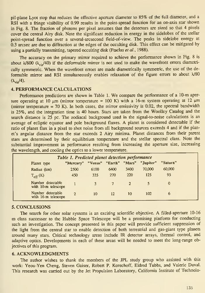
pil-plane Lyot stop that reduces the effective aperture diameter to 85% of the full diameter, and a
RSI with a fHnge visibility of 0.99 results in the point-spread function for an on-axis star shown
in Fig. 8. The fraction of photons per pixel assumes that the detectors are sized so that 4 pixels
cover the central Airy disk. Note the significant reduction in energy in the sidelobes of the stellar
point-spread function over a several-arcsecond field-of-view. The peaks in sidelobe energy at
0.3 arcsec are due to diffraction at the edges of the occulting disk. This effect can be mitigated by
using a partially transmitting, tapered occulting disk (Ftaclas et al., 1988).
The accuracy on the primary mirror required to achieve the performance shown in Fig. 8 is
about V800 (^v^40) if the deformable mirror is not used to make the wavefront errors diametri-
cally symmetric. When the wavefront errors are made diametrically symmetric, the use of the de-
formable mirror and RSI simultaneously enables relaxation of the figure errors to about X/80
4. PERFORMANCE CALCULATIONSPerformance predictions are shown in Table 1. We compare the performance of a 10-m aper-
ture operating at 10 jim (mirror temperature = 100 K) with a 16-m system operating at 12 |im
(mirror temperature = 70 K). In both cases, the mirror emissivity is 0.02, the spectral bandwidth
is 25%, and the integration time is 40 hours. Stars are taken from the Woolley Catalog and the
search distance is 25 pc. The zodiacal background used in the signal-to-noise calculations is an
average of ecliptic equator and pole background fluxes. A planet is considered detectable if the
ratio of planet flux in a pixel to shot noise from all background sources exceeds 4 and if the plan-
et's angular distance from the star exceeds 2 Airy minima. Planet distances from their parent
stars are determined by their equilibrium temperature and the stellar spectral class. Note the
substantial improvement in performance resulting from increasing the aperture size, increasing
the wavelength, and cooling the optics to a lower temperature.
Table 1. Predicted planet detection performance
Planet type "Mercury" "Venus" "Earth" "Mars" "Jupiter"
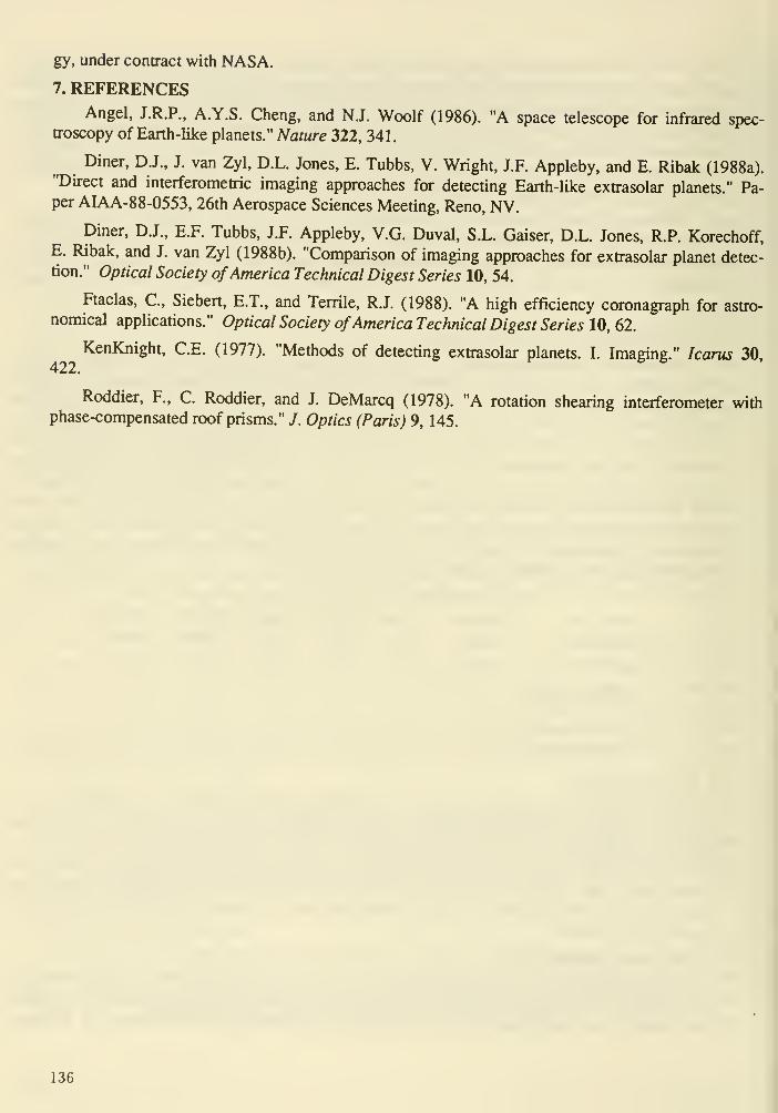
gy, under contract with NASA.
7. REFERENCESAngel, J.R.P., A.Y.S. Cheng, and N.J. Woolf (1986). "A space telescope for infrared spec-
troscopy of Earth-like planets." Nature 322, 341.
Diner, D.J., J. van Zyl, D.L. Jones, E. Tubbs, V. Wright, J.F. Appleby, and E. Ribak (1988a)."Direct and interferometric imaging approaches for detecting Earth-like extrasolar planets." Pa-per AIAA-88-0553, 26th Aerospace Sciences Meeting, Reno, NV.
Diner, D.J., E.F. Tubbs, J.F. Appleby, V.G. Duval, S.L. Gaiser, D.L. Jones, R.P. Korechoff,E. Ribak, and J. van Zyl (1988b). "Comparison of imaging approaches for extrasolar planet detec-tion." Optical Society ofAmerica Technical Digest Series 10, 54.
Ftaclas, C, Siebert, E.T., and Terrile, R.J. (1988). "A high efficiency coronagraph for astro-nomical applications." Optical Society ofAmerica Technical Digest Series 10, 62.
KenKnight, C.E. (1977). "Methods of detecting extrasolar planets. I. Imaging." Icarus 30,
Roddier, F., C. Roddier, and J. DeMarcq (1978). "A rotation shearing interferometer withphase-compensated roof prisms." /. Optics (Paris) 9, 145.
136
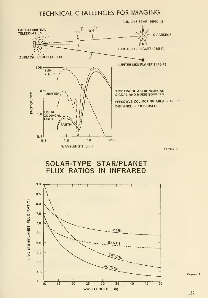
EARTH ORBITINGTELESCOPE .
•..
,
TECHNICAL CHALLENGES FOR IMAGINGSUN LIKE STAR (5800 Kl
0.5''
O^ 10 PARSECS
ZODIACAL CLOUD (300 K)
100
EARTH LIKE PLANET (250 K)
JUPITER LIKE PLANET (125 K)
OlUMZoI-oI
1.0
0.1
SUN / •-,
X 10 " / ^
LOCALZODIACALLIGHT
lOh A\JUPITER; •
SPECTRA OF ASTRONOMICALSIGNAL AND NOISE SOURCES
EFFECTIVE COLLECTING AREA = BOm^
DISTANCE = 10 PARSECS
0.1 1.0 10
WAVELENG1II (pml
100
Figure 1
SOLAR-TYPE STAR/PLANETFLUX RATIOS IN INFRARED
10 15 20 25 30 35
WAVELENGTH (urn)
40 45
Figure 2
137
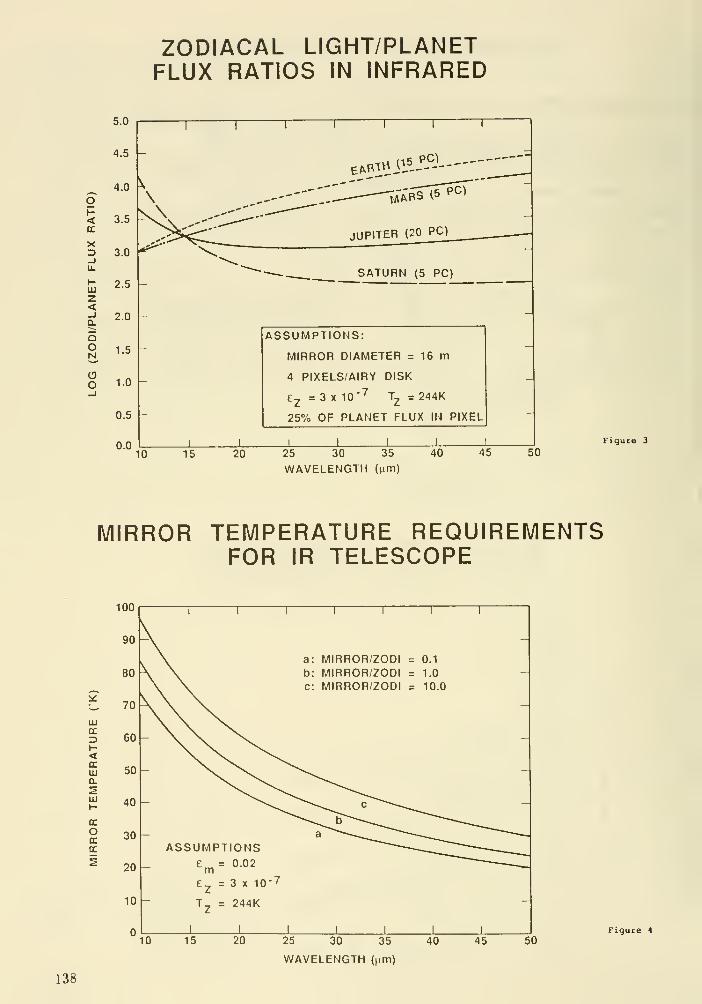
ZODIACAL LIGHT/PLANETFLUX RATIOS IN INFRARED
5.0
OH<tL
X
UJ
z<
ooN
oo
4.5 -
4.0
3.5
3.0
2.5
2.0
1.5
1.0
0.5
0.0
JUPITER (20 PC)
SATURN (5 PC)
ASSUMPTIONS:
MIRROR DIAMETER = 16 m
4 PIXELS/AIRY DISK
3 X 10' T^ = 244K
25% OF PLANET FLUX IN PIXEL
I
10 15 20 25 30 35
WAVELENGTH (Mtn)
40 45 50Figure 3
MIRROR TEMPERATURE REQUIREMENTSFOR IR TELESCOPE
LUCC
<CCUJQ.
UJ
CC
oocCC
uu
90
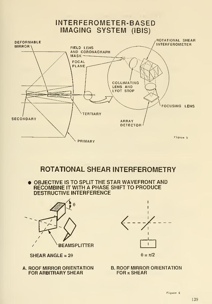
DEFORMABLEMIRROR
SECO
INTERFEROMETER-BASEDIMAGING SYSTEM (IBIS)
ROTATIONAL SHEAREROMETER
FOCUSING LENS
figure 5
PRIMARY
ROTATIONAL SHEAR INTERFEROMETRY
OBJECTIVE IS TO SPLIT THE STAR WAVEFRONT ANDRECOMBINE IT WITH A PHASE SHIFT TO PRODUCEDESTRUCTIVE INTERFERENCE
/ BEAMSPLITTER
SHEAR ANGLE = 29
<- - -/K-
e = 7i/2
A. ROOF MIRROR ORIENTATIONFOR ARBITRARY SHEAR
B. ROOF MIRROR ORIENTATIONFOR K SHEAR
Figure 6
139

STELLAR POINT-SPREAD FUNCTIONNO SUPPRESSION
16-ni diameter X - 12 \un AX/X = 0.25
couo
10
10
10-10
_i 1 i_ J I p
-2 2
Distance from Center (arcseconds)
STELLAR POINT-SPREAD FUNCTIONWITH CORONAGRAPH AND INTERFEROMETER
16-iu diameter X = 12 \.[m AX/X = 0.25
10
Xh.
-2
(/I
coo.ca.
couo
10
10-10
—I r-
_i I L-
-2 2
Distance from Center (arcseconds)
Figure 7
Figure 8
140

DISCUSSION
Layman: Given a bulk mirror temperature of 100°K, what detector temperature is required?
Diner : Probably about 20° K.
R. Green : What are the requirements on the mirror scattering profile at the angular scales of interest
here?
Diner : The figure requirement of A/40 at visible wavelengths is based on calculations of scattering
due to mirror figure ripples on scales of ~20-100 cm. Using the rotationtil shearing interferometer and
deformable mirror relaxes the requirements on the primary to about A/4 in the visible.
Layman: Do micrometeroroid induced surface pits (1 mm to 100 mm pit size) give serious stray light
problems for planet detection? (Assume about 10 pits/ft^)
Diner : These small pits scatter light over a broad field of view. The most detrimental spatial scales
for scattering are tens of cm to a meter, so the small pits, at least qutilitatively, are not expected to
degrade performance.
Wool£ The benefits of the large filled aperture is that by minor modifications in the pupil plane you
can configure an apodized aperture, an interferometer, or even something you have not yet dreamed
up. The really worrisome problem is whether we will have enough control of phase and amplitude
irregularities to benefit from these schemes.
Diner : Right.
Bely: How do you plan to guide the instrument? Using the parent star?
Diner : The one advantage of having the bright central star is that it provides a guiding and phfise
reference. There are a number of places a portion of the stellar signal could be picked off, such as the
back side of the coronagraph mask.
141
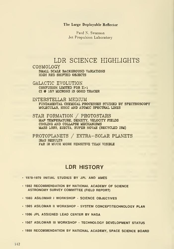
The Large Deployable Reflector
Paul N. SwansonJet Propulsion Laboratory
LDR SCIENCE HIGHLIGHTSCOSMOLOGY
SMALL SCALE BACKGROUND VARIATIONSHIGH RED SHIFTED OBJECTS
GALACTIC EVOLUTIONCONFUSION LIMITED FOR Z>1CI O 157 MICRONS IS GOOD TRACER
INTERSTELLAR MEDIUMFUNDAMENTAL CHEMICAL PROCESSES STUDIED BY SPECTROSCOPYMOLECULAR. IONIC AND ATOMIC SPECTRAL LINES
STAR FORMATION / PROTOSTARSMAP TEMPERATURE. DENSITY. VELOCITY FIELDSCOOLING AND COLLAPSE MECHANISMSMASS LOSS. EJECTA. SUPER NOVAE (RECYCLED ISM)
PROTOPLANETS / EXTRA- SOLAR PLANETSIRAS RESULTSFAR IR MUCH MORE SENSITIVE THAN VISIBLE
LDR HISTORY
• 1978-1979 INITIAL STUDIES BY JPL AND AMES
• 1982 RECOMMENDATION BY NATIONAL ACADEMY OF SCIENCEASTRONOMY SURVEY COMMITTEE (FIELD REPORT)
• 1983 ASILOMAR I WORKSHOP - SCIENCE OBJECTIVES
. 1985 ASILOMAR II WORKSHOP - SYSTEM CONCEPT/TECHNOLOGY PLAN
• 1986 JPL ASSIGNED LEAD CENTER BY NASA
• 1987 ASILOMAR III WORKSHOP - TECHNOLOGY DEVELOPMENT STATUS
• 1988 RECOMMENDATION BY NATIONAL ACADEMY, SPACE SCIENCE BOARD
142

LDR: TWO - STAGECONFIGURATION
HOLE TO SKY
SECONDARY
THERMALSHIELD
SUNSHIELD10 - MfTER
SUNSHiaD
SECOND STAGE
FOCUS
• DEDICATED ASTRONOMICAL OBSERVATORY FOR THE 1990'S
• 20MF/0.5, PASSIVE PRIMARY REFLECTOR. DIFFRACTION LIMITED AT 30-50 MICRONS
• FOUR MIRROR, TWO-STAGE OPTICS
• ACTIVE QUATERNARY MIRROR
• 84 LIGHTWEIGHT PRIMARY REFLECTOR SEGMENTS, 2M SIZE. <10 KG/M AREAL DENSITY
• OVERALL SURFACE ERROR <3 MICRONS RMS
• ACTIVE CONTROL SYSTEMS FOR FIGURE, POINTING, VIBRATION
• SURFACE FIGURE MEASUREM.ENT SYSTEM
• SUNSHADE FOR THERMAL CONTROL
• FOCAL PLANE INSTRUMENTS COVERING 30-1000 MICRON SPECTRAL RANGE; CRYOGENIC,
COHERENT NON-COHERENT
• SPACE STATION ASSEMBLY
143
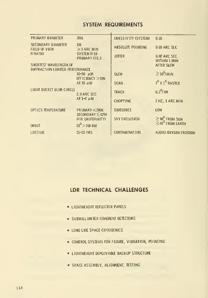
SYSTEM REQUIREMENTS
PRIMARY DIAMETER 20M

DIAMETER VS. RMS SURFACE ERRORFOR SOME WELL KNOWN TELESCOPES
0.01 0.1 1 10
Surface Error (microns rms)
100 1000 10000

10
10 -
X
10
10
10
10
)-M
* Reproduced from SPIE paper delivered in Orlando, Florida on April 2, 19S^.
PAMELA: High density segmentation for large, ultra-light,high performance mirrors.
J, D. G. Rather, B. L. Ulich, Kaman Aerospace CorporationG.Ames, A. Lazzarini, Kaman Instrumentation Corporation
E. K. Conklin, FORTH, Inc. and D. Korsch, Korsch Optics, Inc.
ABSTRACT
This paper provides the first public disclosure of anoptical technology which makes possible important newopportunities for the construction of very large telescopes.This technology, developed by Kaman Corporation in anIndependent Research and Development program extending overthe past several years, is generically known as PAMELA™, anacronym for Phased Array Mirror, Extendable Large Aperture.Kaman 's patented PAMELA^ approach leads directly to theability to build rugged, diffraction-limited opticaltelescopes or beam expanders for ground-based or orbitaldeployment that have unprecedentedly low weight. Inaddition, the entire optical system will be fault-tolerant,leading to large expected savings in overall system cost andcomplexity. These attributes make PAMELA™ a prime candidatetechnology to benefit both civilian and military opticalsystems in such areas as laser applications, imaging, remotesensing, and communications. PAMELA™ will also have broadapplicability to the needs of astronomy.
1.0 INTRODUCTION
The search for new, less expensive, and better ways to build anddeploy large optical telescopes both on the ground and in space hasreceived much attention over the past decade. Although numerousinnovations have been attempted, optical systems built by existingmethods are still very expensive, fragile, and demanding of time andtalent. Breakthroughs in optical design, fabrication, and control areessential if a wider range of applications are to be addressed bylarge, lower-cost optical systems. Here we report such a breakthroughthat should render large scale adaptive optics applications feasible.
The development of the technologies supporting Kaman 's PAMELA™concept has been guided by carefully conceived studies of end to endstrawman systems. The estimated primary mirror weights derived fromthese studies, if realized, would represent significant advancement ofthe state-of-the-art. Figure 1-1 provides a graphical comparison ofthe primary mirror weight (including all supporting structure in themirror cell) for PAMELA™ mirror technology compared with existingachievements using more conventional optical technologies. The
147

specific mass (kg/m ) of a PAMELA™ mirror will be at least four timeslower than that of any previous mirror technology; and, moreimportantly, this specific mass will be preserved as the mirroraperture is scaled upward to 2 meters or more.
2.0 DISCUSSION
The idea of making large telescope primary mirrors from manysmall mirrors can be traced back well into the 19th century. Indeednumerous attempts have been made to build such telescopes; but, withonly a few exceptions, they have functioned only as "light buckets"rather than true imaging devices because the individual small mirrorscould not be kept phased to the requisite precision. If theirregularities in the optical surface exceed a few percent of thewavelength of light, diffraction limited performance cannot beachieved.
Kaman's PAMELA^ approach depends upon innovative improvements inthe states-of-the-art of adaptive optics sensing, actuation, andcontrol techniques. Basically, the PAMELA™ approach depends uponmass-produced small segments which can move at high frequencies withgreat precision to correct for optical errors both intrinsic andextrinsic to the telescope. This permits the use of very low-weight,easily deployable mounting surfaces for the segments. Though themechanical structure and optical train may have many dynamical
MIRROR AREAL MASS DENSITIES AS AFUNCTION OF SEGMENT SIZE
200
180

imperfections, the agile PAMELA™ segmented surface functions as a
massive, parallel-processing automaton to generate the conjugatesurface which cancels all of the errors, thus restoring nearlydiffraction-limited performance.
All previously known adaptive optics wavefront correction schemesutilize methods for generating a so-called conjugate wavefront byreversing the spatial phase of a propagating wave at (or through) somesub-element of the optical system (such as a tertiary deformablemirror) . Hence the optical ray bundles must be reduced to relativelysmall size in comparison with the primary optical element before therequired conjugate wave corrections can be applied. These existingmethods have several disadvantages compared with PAMELA™ , includinglimited spatial frequencies, limited phase adjustment ranges of only a
few wavelengths, and limited ability to cope with the very largeintensity associated with high power laser beams, to mention a few.The PAMELA™ approach circumvents all of these limitations.
While the PAMELA™ approach is described here as applied to theprimary mirror of an optical system, the method is completely generaland can be applied to any subsidiary element of the beam train aswell. In most instances, however, great benefits of cost and systemsimplicity will result from putting the PAMELA™ segments on thesurface of the large primary reflector.
The PAMELA™ concept involves synthesizing a large optical surfacefrom hexagonal segments whose size approximates that of thedisturbance coherence dimension, r , associated with the wavelengthsof interest. For ground-based or airborne applications, r isdominated by atmospheric disturbances, which typically set the segmentscale to <5 cm at -0.5 micron wavelength. Surprisingly, also inspace-based applications relatively small-sized PAMELA™ mirrorelements are still found to be desirable to minimize system weight andto correct for small scale structural resonances and optical rayaberrations associated with thermal effects and low weight telescopeconstruction. As the mirror elements are made smaller, they alsobecome thinner and hence lighter. Materials such as crystallinesilicon or silicon carbide become usable, wherein the much greaterstiffness contributes to further weight reduction. Moreover, smallsegments are very amenable to inexpensive replication andmanufacturing processes. The segments for a PAMELA™ telescope are notsimple mirrors, but, rather, they are hicfhlv sophisticated miniaturemachines possessing large digital computing power in their owninternal electronics together with ultra-precise measuring sensors andposition actuators on each segment. Indeed, the PAMELA™ conceptrepresents the first large scale direct application of the economiesof the silicon microprocessor industry to optical components. Most ofthe wavefront reconstruction process that generates the requiredconjugate surface is accomplished economically and very rapidly (>10kHz) by the microprocessors in the segments, which function as amassive, parallel-processing network. Central control is alsomaintained from a small and economical master computer whichcommunicates with each segment by a two-way optical fibre link.
149

Figure 2-1 illustrates the PAMELA™ mirror concept, showing theindividual segments grouped into clusters which in turn make up themirror surface. Each of the individual segments has threeelectromagnetic piston actuators and three active inductive edgesensors (the other three alternate edges have passive elements foredge sensors associated with adjacent active segment edges). Thepiston actuators move in response to control signals from both aglobal wavefront error sensing device and the local edge sensors Theend result of precisely controlled segment motion is an opticalsurface that behaves like a phase conjugating continuous facesheetmirror, but with much larger dynamic range and much simpler and fastercontrol algorithms and technology.
The long stroke afforded by the PAMELA™ actuators provides theuniquely important capability for modulo-zero corrections over >200wavelengths (i.e. without 2n7r phase ambiguities). This propertyprovides the stroke dynamic range to compensate easily for the largestwavefront aberrations that can be imposed by mechanical or thermaldisturbances to the ray path. Hence, very lightweight supportstructures can be used to support the segments, which are, themselvesvery light weight and thus highly mobile with only small power inputto the actuators. ^
Segment
Clusterol Segments
Full Aperture
Figure 2-1. PAMELA™ active segments will be mass producedin clusters which can be combined to form arbitrarily laraeapertures. Micro-electronics on each segment drivesactuators to achieve a quasi-continuous surface whichDenaves as a phase conjugating membrane mirror having hiqhfrequency response and long-throw adaptive capability
150

This leads to large potential savings in weight and cost.Moreover, since the primary segments are demagnified back through theoptical train, they can correct for small scale, large amplitudedisturbances occurring anywhere in the telescope system, such asthermal distortions on secondary mirrors and vibration induceddisturbances in the ray path.
The optical quality of images provided by highly segmentedmirrors has been carefully compared to the quality of images fromfilled apertures. The amount of energy in the central lobe of thediffraction pattern is comparable to that for a filled aperture, andthe image quality will be comparable. Six-sided diffraction spikeswill show only for very bright point sources, just as four sidedspikes occur in conventional systems from the secondary mirrorsupports. Scattering of light from segment edges will lower imagecontrast very slightly, as predicted by the Ruze theory familiar toradio astronomers. As long as phase continuity is maintained, theimages from a PAMELA™ array will be excellent. Similarly, in the caseof laser beam expanders, the Strehl ratio will approach 87% at 0.5 /im
wavelength for the expected surface roughness of 0.025 /im, and theamount of power diffracted or lost between the inter-segment gaps willbe less than 0.6 percent.
A set of baseline requirements were adopted during Kaman's PAMELAIR&D effort. These requirements are listed in Table 2-1.
TABLE 2-1 BASELINE CONCEPT FOR PAMELA
2* Large Aperture (scalable to area >100 m )
* Many Segments (scalable to n >20,000)* Active Wavefront Control on the Primary Mirror* Large Dynamic Range (>100 /zm with 20 nm accuracy per
element)* High Temporal and Spatial Bandwidth (atmospheric and optics
train correction capability)* High Power Throughput* Mass-Produced Active Mirror Segments (low cost)* Near Diffraction Limited Operation for A = 0.5 /im
* Modularity of Adaptive Surface and Control System
Since Kaman Corporation has developed and produced for many yearsa broad range of precision displacement measuring instrumentation, itwas possible to develop hardware based on existing technology that hasthe potential for meeting the stringent requirements of PAMELA™telescopes. Initial design and construction of these hardwarecomponents has been carried out, and the experimental data obtainedfrom tests show the required performance characteristics.
Some of the key findings that evolved out of the IR&D effort atKaman are summarized below:
1) The segmented primary mirror using small, lightweight,essentially identical segments has very significant advantages interms of ease of component fabrication, ruggedness of the system.
151

overall system weight, and cost.
2) The formidable computing problem associated with reconstructing avisible wavefront over a large mirror surface from tilt I
measurements can be greatly reduced by use of the technologicallyattractive edge matching techniques to preserve phase and local]parallel processing to simplify the control problem.
3) Edge matching of segments can be done iteratively with good]convergence accuracy.
4) New edge matching sensors devised by Kaman are feasible on theedges of segments as small as 2 cm.
5) New electromagnetic piston actuators, conceived and designed byKaman, are needed since existing actuators (PZTs, PMNs, etc.)have inadequate stroke to achieve the large displacementsrequired to correct errors in low-weight telescope structures.Moreover, the cost of Kaman 's actuators is expected to be muchless than that of conventional actuators.
The baseline concept adopted for PAMELA™ places additionalconstraints on the measurement and control process. Co-existence of asensitive metrology system with an imaging or laser system leads tothe need for multi-wavelength or broad-band operation, which implies acontinuous or quasi-continuous surface; 2n7r ambiguities in therelative phase of individual elements are not acceptable. Neardiffraction limited operation at visible wavelengths requires aclosed-loop segment correction bandwidth of several kHz for typicalcomposite system fluctuations. A general requirement for robustnessand reliability in the system leads to a strong preference fordistributed processing and as much local autonomy in the individualsegments as possible.
In the extensive research performed by Kaman to date, numerousapproaches for wavefront control were studied in detail. Three ofthem would work; each has advantages and disadvantages. However, whena full systems analysis approach was applied to the entire telescopesystem, one wavefront control approach was found to be the mostpractical, scalable, and inexpensive solution.
In this method, a global wavefront tilt sensor designed by Kamanprovides two-axis tilt information to each segment via an opticalfibre data link. The edge sensors on the segments are then used toderive additional piston information to drive the segments to acontinuous surface condition. This method uses well-establishedtechnology which is very sensitive and inherently satisfies therequirement for non-dispersive performance at multiple wavelengths.
Since segment tilt information is basically the local derivativeof the phase (which is the required quantity) , complex signalprocessing is required. A typical straightforward mathematicalapproach to the problem (frequently utilized in present adaptiveoptics systems) derives phase directly through the inversion of an
152
extremely large matrix, on the order of the square of the number ofsegments, and requires a different solution for each permutation ofmissing or non-functioning tilt sensors. While this is feasible forsmall adaptive optics systems, it is very difficult for a system withpotentially several tens of thousands of elements. However thereexist a number of iterative methods which use tilt informationdirectly to set the surface, and which appear practical for systemsthe size of PAMELA. These methods require a computation ratesubstantially higher than the phase disturbance bandwidth, but recentadvances in microprocessor electronics make such computations not onlypractical but cost-effective. Thus, a systems analysis approachindicates Kaman's new measurement and control concept to be thepreferred one. Its complexity lies not in the wavefront sensor, adifficult area, but in the computation algorithm, which is now wellunderstood.
3.0 VALIDATION
The results of Kaman's studies provide the basis for ourconfidence that an edge-matched large array is feasible. Someinteresting experiments can be reported.
1) Edge Sensors . An essential element of the proposed segmentedmirror concept is the existence of a sensor which is capable ofaligning the edges of adjacent segments in order to form whatapproximates a continuous "face-sheet" surface. This must bedone to an accuracy of a small fraction of the wavelength oflight. All existing sensing technologies were evaluated, withparticular attention given to inductive, capacitive, and opticaldevices. The inductive sensor, which Kaman has investigated indepth, emerged as the most promising technique due to itsinherently stable zero reference point, high resolution, widedynamic range, low sensitivity to gap changes and environmentalchanges, and low complexity signal conditioning.
2) Circuit development, testing, and integration . First generationsignal conditioning circuits have already been integrated onsilicon using semi-custom CMOS technology.
3) Computer modeling . Kaman has developed a computer model whichfacilitates simulation of the performance of large arrays ofsegments subjected to diverse perturbations.
4) Actuator design . To achieve the required long-throw displacementof the segments, a new type of actuator has been designed.
5) Segment Fabrication . Several preliminary segment fabricationtechniques have been explored. The most promising thus far haveutilized crystalline silicon and silicon-carbide for thesubstrate. Two types of silicon carbide fabrication methods arecurrently being evaluated under the ongoing IR&D effort. Figure3-1 shows one example of a test segment which is dynamically flatto X/20.
153

6) Validator . A test device has been built which has successfullydemonstrated edge match of a fully mobile center segmentsurrounded by displaceable segments. The edge sensors perform asexpected, giving repeatable white light fringes on a Michaelsoninterferometer. Figures 3-2 and 3-3 show the validator deviceand a typical fringe pattern.
Figure 3-1. Silicon carbide segment (rear view)
154

Figure 3-2. Dynamic segment validator.
ip'
Figure 3-3. Continuity of fringes across gap between twoedge-matched segments.
155

DISCUSSION
Miller : What is the mirror surface? Is it silicon?
Rather : There are various ways of preparing the surface. The ones available now are a bonded silicon
surface on the silicon carbide. There are a few manufacturers. One of the best is made by United
Technologies Optical Systems in West Palm Beach.
Bnrbidge: You said that the cost is down by a factor 5-10. How do you demonstrate that?
Rather : It depends on the economies of mass-production. It is still uncertain but it comes from
programs for evaluating the cost of meiss-production.
Nelson : For a 10-16 meter telescope, how small do the segments have to be to approximate the surface
with spherical segments?
Rather : There are many tradeoffs, but I would say no bigger than 15 cm, and probably 7 cm, but
Korsch can answer that since he has been looking at this question.
Korsch : If the segments are sufficiently smeill, the shapes of Ceissegrain-type and R/C-type primaries
may be approximated by simpler segment shapes. The segment sizes allowing a spherical approximation
will probably be too small (less than 1 cm), but relatively simple toroidal shapes will most likely be
adequate.
156
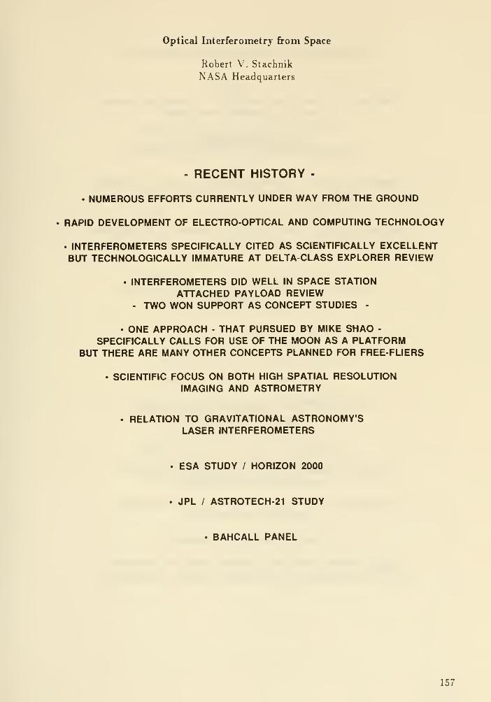
Optical Interferometry from Space
Robert V. Stachnik
NASA Headquarters
- RECENT HISTORY -
• NUMEROUS EFFORTS CURRENTLY UNDER WAY FROM THE GROUND
RAPID DEVELOPMENT OF ELECTRO-OPTICAL AND COMPUTING TECHNOLOGY
• INTERFEROMETERS SPECIFICALLY CITED AS SCIENTIFICALLY EXCELLENTBUT TECHNOLOGICALLY IMMATURE AT DELTA-CLASS EXPLORER REVIEW
• INTERFEROMETERS DID WELL IN SPACE STATIONATTACHED PAYLOAD REVIEW
- TWO WON SUPPORT AS CONCEPT STUDIES -
• ONE APPROACH - THAT PURSUED BY MIKE SHAO -
SPECIFICALLY CALLS FOR USE OF THE MOON AS A PLATFORMBUT THERE ARE MANY OTHER CONCEPTS PLANNED FOR FREE-FLIERS
• SCIENTIFIC FOCUS ON BOTH HIGH SPATIAL RESOLUTIONIMAGING AND ASTROMETRY
. RELATION TO GRAVITATIONAL ASTRONOMY'SLASER INTERFEROMETERS
• ESA STUDY / HORIZON 2000
. JPL / ASTROTECH-21 STUDY
• BAHCALL PANEL
157
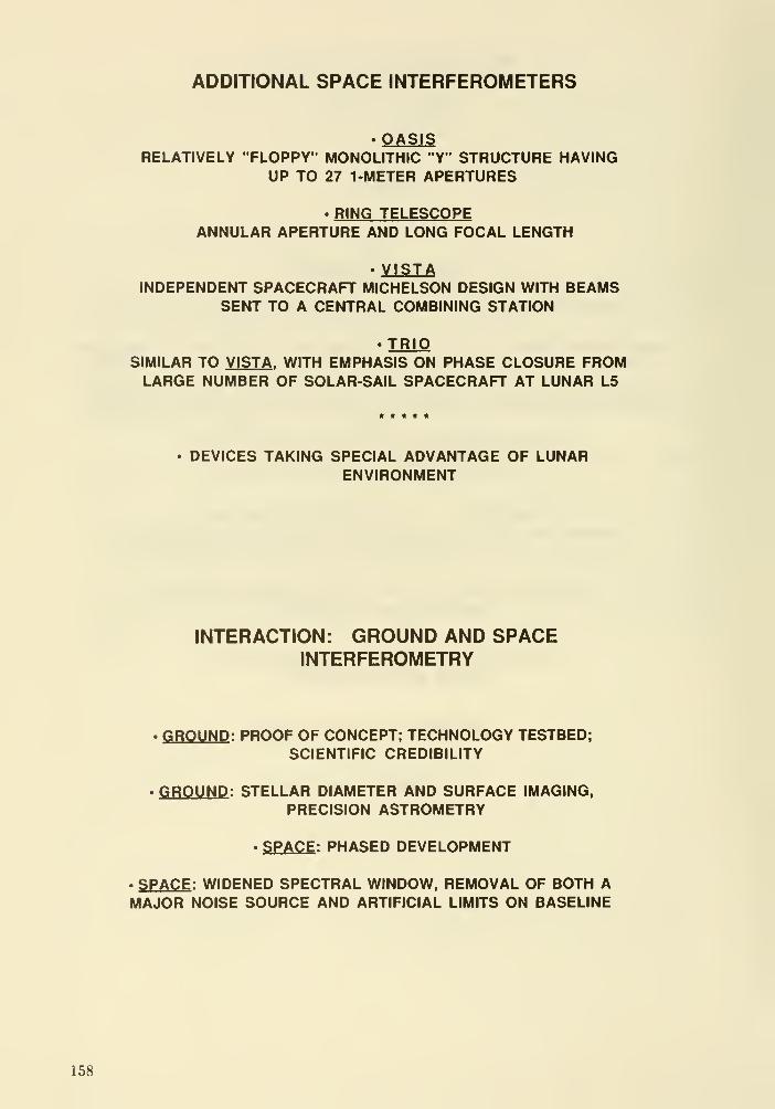
ADDITIONAL SPACE INTERFEROMETERS
' OASISRELATIVELY "FLOPPY" MONOLITHIC "Y" STRUCTURE HAVING
UP TO 27 1 -METER APERTURES
RING TELESCOPEANNULAR APERTURE AND LONG FOCAL LENGTH
» VISTAINDEPENDENT SPACECRAFT MICHELSON DESIGN WITH BEAMS
SENT TO A CENTRAL COMBINING STATION
• TRIOSIMILAR TO VISTA . WITH EMPHASIS ON PHASE CLOSURE FROMLARGE NUMBER OF SOLAR-SAIL SPACECRAFT AT LUNAR L5
. DEVICES TAKING SPECIAL ADVANTAGE OF LUNARENVIRONMENT
INTERACTION: GROUND AND SPACEINTERFEROMETRY
• GROUND : PROOF OF CONCEPT; TECHNOLOGY TESTBED;SCIENTIFIC CREDIBILITY
• GROUND : STELLAR DIAMETER AND SURFACE IMAGING,
PRECISION ASTROMETRY
• SPACE : PHASED DEVELOPMENT
. SPACE : WIDENED SPECTRAL WINDOW, REMOVAL OF BOTH AMAJOR NOISE SOURCE AND ARTIFICIAL LIMITS ON BASELINE
158

INTERACTION: MONOLITHIC ANDSYNTHESIZED APERTURES
• A CONTINUUM !
FILLED => VERY DILUTE
• RECALL THE EXPERIENCE OF THE RADIOCOMMUNITY
ANDLOOK AT THE VLT
• DESIGNING ANY NEW LARGE MONOLITHTO BE COMPATIBLE WITH AN
ASSOCIATED ARRAY WILL BECOMEINCREASINGLY DESIRABLE
. SCIENCE, AT PRESENT, LOOKSSOMEWHAT ORTHOGONAL.
THE DISTINCTION IS LIKELY TODISAPPEAR WITH TIME, AS HAS BEEN THE
CASE FOR THE RADIO COMMUNITY
• IN THE SHORT TERM, DESIGNS OF BOTHSYNTHETIC AND MONOLITHIC APERTURE
INSTRUMENTS WILL ADDRESSCOMPLEMENTARY SCIENCE. THIS WILL BELESS TRUE IN THE FUTURE . DESIGNERSOF BOTH TYPES OF INSTRUMENTS
SHOULD CONSIDER THE NEEDS OF THECOMBINED COMMUNITY OF USERS
159

Direct IR Interferometric Detection of Extra Solar Planets
Michael Shao
Jet Propulsion Laboratory
Abstract
This paper describes a concept for the direct detection of extrasolar planets. The concept is based on a decade old idea fromBracewell but expanded. A long baseline interferometer is examinedwith two three meter telescopes, cooled to 70K and a baseline of30-50 meters. In space, this instrument would be able to detect anEarth sized planet around a solar like star at 10 parsec inapproximately 1 hour of integration (5 sigma) . The total number ofcandidate stars with detectable "Earths" number in the thousands.
I Introduction
Several techniques have been proposed that in theory would becapable of detecting Earth like planets around nearby stars. The IRlong baseline interferometer technique described here, has asignificant cost advantage of a factor of 10 to 30, $500M vs $5-15Bor $1B vs $10-308. The technique is based on using a long baselineinterferometer with an achromatic nulling beam combiner topartially cancel the light from the star so that the IR light fromthe planet can be detected.
The major sources of noise in IR direct planetary detection a;
1) Light from the star, diffracted or scattered into the detectopixels that would otherwise detect planetary emission.
2) Thermal emission from the optics3) Zodiacal IR emission from dust within the solar system (near
the earth's orbit, this dust has an emissivity of 1.0 e-7and a temperature of 277K)
.
4) Zodiacal IR emission from the dust around the star where we a
searching for planets.
In direction detection of extra solar planets at visiblewavelengths, #1 in the above list is the most severe problem. At IRwavelengths, depending on the design of the instrument, any of theabove four effects can dominate.
Bracewell in the mid 70 's, first proposed the idea of using a spacebased IR interferometer to extra solar detect planets. A study ofthe concept by Lockheed for NASA Ames, was conducted with thedetection of a Jupiter sized planet at 10 parsec as the goal of the"baseline" instrument. The detection of smaller but much warmerplanets such as Earth, or Venus was not considered. It turns outthat in many ways the detection these warmer planets with IRinterferometry, is not significantly more difficult.
Fig. 1 shows the difference between detecting the emission of aextra solar planet at visible and IR wavelengths. By moving into
160

Figure 1
Relative Sun - Earth photon flux vs wavelength
photons/um/sec relative
10,000.000.000 r
100.000.000 r
1.000.000
10.000
100
0.01
0.2
I
0.5 2 5
microns
10 20 50
the IR two advantages are gained, one the contrast ratio betweenthe star and planet improves by about 3 orders of magnitude,
^
second, the number of IR photons per second from the planet isactually larger in the IR. For detection of Earth like planets,detection at lOum is optimum.
While the detection of an Earth-Sun system at 10, 2.5 or 4 parsecis a useful objective, it is also important to determine the numberof candidate stars around which a planet could be detected, if a
planet were there. Here the advantage of a long baselineinterferometer becomes apparent. An Earth-Sun system at lOpc wouldhave an angular separation of 0.1 arcsec, requiring a baseline of25 meters to resolve (or a 25 meter filled aperture telescope)
.
However, the vast majority of stars in the solar neighborhood aremuch less luminous and the separation of an Earth like planet fromthe star would be much smaller, requiring corresponding longerbaselines. While an interferometer with 2 3meter apertures (15 sqmeters) would be 10-30 times less expensive than a 16 m filledaperture telescope, it would be an additional order of magnitudeless expensive than a 50-100 meter telescope that would be capableof detecting hundreds to a thousand planets that the 3minterferometer would.
II IR Long Baseline Interferometer in Space
For an example, we consider a long baseline interferometer with two3 meter aperture telescopes, and a baseline of 30-50 meters. Weassume that the baseline can be extended so that the star-planet is
161

Figure 2
Planetary Achronatic Nulling Interferoneter Concept
This is just 1 exQnple (other achronatic nulling interf. exist)
Mirror
V^
^WCorner cube
-y
Each am sees 1 T, I R off bean splitter
Noma! bean splitter , not 50/50
Null due to polarization flip, not DPD shift, wideband
resolved by the interferometer. Fig. 2 shows the basic idea of theinstrument. Light from the two telescopes are brought together toan achromatic nulling beam combiner. In a conventional pupil planeinterferometer such as the one studied by Lockheed, the starlightwas nulled out by changing the path in one arm of theinterferometer by 1/2 wave. However, a physical change of 1/2 waveat lOum wavelength would not be exactly 1/2 wave at 10.1 urn. Theinterferometer in Fig. 2 gets around the problem by producing anull (dark fringe) at zero optical path difference by flipping thepolarization of one of the interfering beams. This particularinterferometer also uses the beam splitter in a symetrical way,light from both telescopes will use the beamsplitter once intransmission and one in reflection. This gets around the problem offabricating a beamsplitter that is exactly 50/50. In fact, almostany dielectric beamsplitter with < 1% absorption will be capable ofnulling out the starlight by a factor of 10,000.
The pointing and phasing of the interferometer are important if ahigh degree of starlight cancellation is desired. Pointing errorswill cause the interfering wavefronts to be tilted with respect toeach other. The optical path difference must be almost equal forthe null to be deep. Typically at 10,000 attenuation of stellarsignal, the optical path must be equal to 20 nanometers rms. Thisimplies the precision (optical figure) a factor of several lesssevere than the optical quality of the Hubble telescope optics. Inaddition the use of a single mode spatial filter before thedetector could be used to relax the optics quality by an order ofmagnitude.
162

Interferometric cancellation requires that the amplitude of theinterfering wavefronts be equal to 1% for cancellation of 10,000.This is met by using a dielectric beam splitter that has less than1% absorption in a symmetrical way such as in fig 2 . In addition thepointing of the telescopes must not move the image more than 1/2of the diffraction spot or about 1/3 arcsec. Control of theoptical paths in the two arms must also be controlled at the 20nmlevel. This would be accomplish by using a dichroic beam splitterto split the vis/near ir light to a separate interferometer. Sincethe central star is quite bright centering the fringe to 20nm atvisible wavelengths is actually quite a bit simpler than theoperation of a ground based interferometer that has to track themillisec fluctuations due to atmospheric turbulence.
Ill SNR calculation
The SNR calculation is quite straightforward. The assumptions are:
1) The star is the size of the Sun, a black body at 5700K.2) The planet is the size of the Earth at 300K.3) Both are a distance of 10 parsec (unit emissivity)4) The local zodiacal dust is a gray body at 277K and an
emissivity of 7.0 e-8.5) The dust around the distant star-planet is similar, 274K
and emissivity of 1.4 e-7 . The emissivity is twice as highbecause in looking out of the solar system we only see 1/2of the dust.
6) The planetary signal is collected by 2 3 meter telescopes7) The area-solid angle product for background is lambda squared
100 square microns8) The optics is at a temperature of 70K with 20% emissivity.9) The detection bandwidth is 20% (9-llum)10) The detector Q.E. is 50%.11) The interferometer cancels star light by a factor of 10,00012) The center of the band is at lOum13) Assume that IR detector noise well below background of 10,000
photons/sec, eg read noise of «300 electrons if detector is rout once per 10 sec.
source
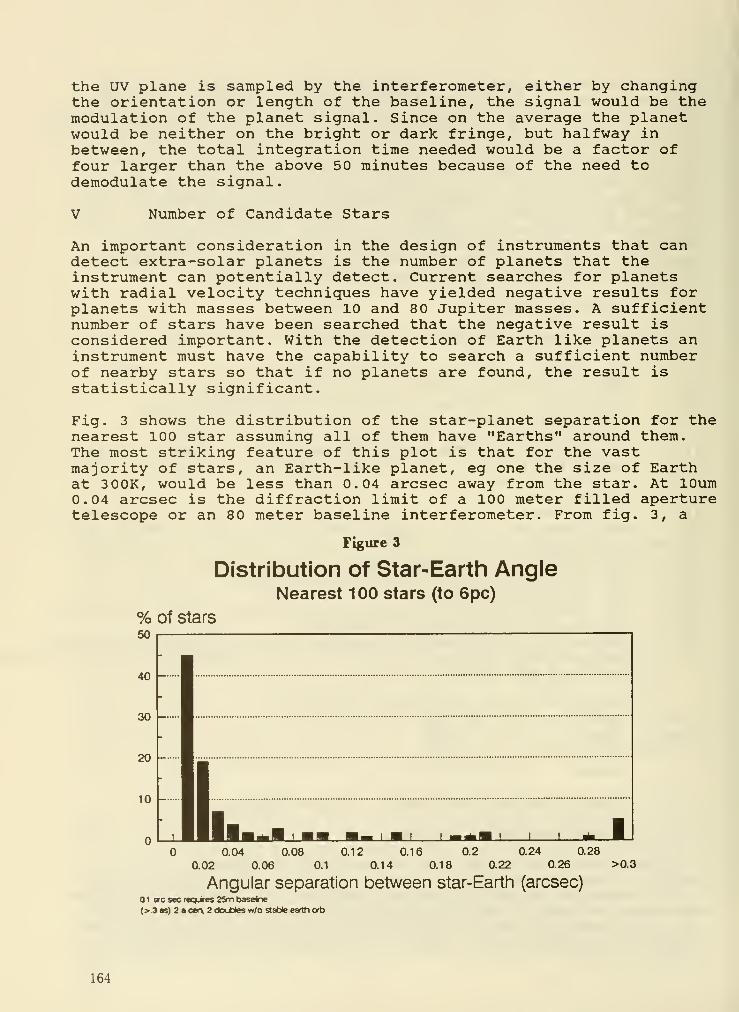
the UV plane is sampled by the interferometer, either by changingthe orientation or length of the baseline, the signal would be themodulation of the planet signal. Since on the average the planetwould be neither on the bright or dark fringe, but halfway inbetween, the total integration time needed would be a factor offour larger than the above 50 minutes because of the need todemodulate the signal.
V Number of Candidate Stars
An important consideration in the design of instruments that candetect extra-solar planets is the number of planets that theinstrument can potentially detect. Current searches for planetswith radial velocity techniques have yielded negative results forplanets with masses between 10 and 80 Jupiter masses. A sufficientnumber of stars have been searched that the negative result isconsidered important. With the detection of Earth like planets aninstrument must have the capability to search a sufficient numberof nearby stars so that if no planets are found, the result isstatistically significant.
Fig. 3 shows the distribution of the star-planet separation for thenearest 100 star assuming all of them have "Earths" around them.The most striking feature of this plot is that for the vastmajority of stars, an Earth-like planet, eg one the size of Earthat 300K, would be less than 0.04 arcsec away from the star. At lOum0.04 arcsec is the diffraction limit of a 100 meter filled aperturetelescope or an 80 meter baseline interferometer. From fig. 3, a
Figure 3
Distribution of Star-Earth AngleNearest 100 stars (to 6pc)
% of stars50
0.04 0.08 ai2 0.16 0.2 0.24 0.28
0.02 0.06 0.1 0.14 0.18 0.22 0.26 >0.3
Angular separation between star-Earth (arcsec)ai arc sec reqLires 2Sm baseine
(>.3 as) 2 a C8r\ 2 doubles w/o stable earth orb
164
200m baseline is needed to detect Earth like planets around 50% ofthe nearest 100 stars (with 6 parsec) . For stars further away than6 parsec, on the average, longer baselines are needed. Radioastronomy went from filled apertures to interferometers becauseimportant scientific questions required very high angularresolution that was achievable in an affordable way only withmultiple telescope interferometry. 100 or 200 meter telescopes inspace or on the Moon are not practical or affordable in theforeseeable future. Three multi-hundred meter optical inter-ferometers (ground based) are funded the Australian interferometerSUSI, the NRL imaging array and the ESO Very Large Telescope.
Interferometers have no intrinsic advantage over filled aperturetelescopes. The advantage is economic, diffraction limited 100 to2 00 meter filled aperture telescopes are extremely expensive, evenat radio wavelengths, at optical wavelengths 100,000 times smaller,they are not affordable.
VI SNR summary
In the calculations above, an interferometer with 3 meter apertureswas used to detect Earth like planets at 10 parsec. For starscloser than 10 parsec, the required apertures are smaller. In theabove example, the nulling interferometer was assumed to cancel thestarlight by a factor of 10,000. For stars with luminosity greaterthan the sun, the factor of 10,000 is not sufficient. Fortunately,the vast majority of stars in the solar neighborhood are lessluminous and a factor of 10,000 is not needed. A large number ofvariables are involved and optimization of an instrument design iscorrespondingly complicated. As an example we consider therequirements for an interferometer to detect an Earth aroundBarnard's Star.
Table 1. IR Interferometer for Direct Detection (Barnard's Star)
• Abs mag 13.2 Visible
• dist 1.9pc
• Star/Earth ratio @10um 400,000 (600 times
zodi)
• I nterferometric cancellation factor of 600
• Star-Earth separation 0.012 arcsec
• Baseline needed 250 m
• Aperture needed 60 cm
• Integration time ~1 hr
• (30cm, *300, 16hrs) also works
Fig. 4 shows roughly, the degree of starlight cancellation requiredas a function of the star's absolute magnitude. Also plotted is thedistribution of the density of stars as a function of absolutemagnitude. Since the vast majority of stars are significantlyfainter than the sun the degree of starlight cancellation (at lOum)
165

would be less than 10,000 in the 1st example with 3m apertures.With 3m apertures, the interferometric cancellation needed is theflus ratio (star/planet) divided by 2500 to get star light equalthe zodiacal light level.
Stellar Density #*10000/cu pc140
10um Flux Ration Star/Earth1.0C€+08
- 5.00E+07
Figure 4
OOE+05(5) 5 10 15 20
Absolute stellar Magnitude (10pc)
Density Flux Ratio
For 16hf Irtegration 2o<*planet=2500 (SNR=5)
Irterferometnc Carcelatian= F.Ry2S00
Fig 5 shows the number of candidate stars as a function ofcollecting aperture. With 3 meter apertures, the number of Earthsthat could be discovered, is over 1000.
# Candidate Stars vs Aperture
# Earth-star candidates
10.000 !-
1.000 r-
Figure 5
ai 02 0.3 05 1 2
Diameter Meters4 hit invf^vtor^poin (9MU4
• >100m««t wididtoi worn ««•
166

Conclusion
A number of techniques exist for the direct detection of extra-solar planets. Long baseline interferometry in the thermal IR has
one compelling advantage. It is capable of detecting "Earths"around nearby stars with collecting apertures, and cost, an order
of magnitude lower than other techniques. In addition, in the long
run it is the only technique that can achieve the very highresolution needed (<0.01 arcsec) to perform a complete survey of
nearby stars for "Earth" like planets.
DISCUSSION
Angel: You have considered using a two-element interferometer with two 3-meter apertures. With
a filled aperture and the apodizing system discussed yesterday, in an exposure of two minutes, an
earth-like planet would be seen in a 0.25" ring around a star at 4 parsecs. One would explore a region
with 6 resolution elements in the image space unambiguously in 2 minutes at the 5 sigma level. For
comparison, for the two 3-meter telescope interferometer, putting in the same conditions and the same
zodiceil light "background", one would get a single metisurement, not an image, at one fringe spacing at
a single orientation, and that would take several hours. At the end we would know only that the fringe
contrast would be slightly reduced by some object in the field. To make a map with any semblence of
the detail from the filled aperture image, many orientations would have to be done. This would result
in days of integration.
Shao : Let me respond to that. The standard algorithm is that the dynamic range of a map is the S/N
per u-v point divided by the number of u-v points. So if there are 25 u-v points each with a S/N of 1,
that produces a map with a S/N of 5. That is the case for a large number of pixels. The radio maps
are done that way. The S/N per individual baseline can be quite low if you have a large number. The
number of u-v points needed are the number of pixels in the map that one is trying to reconstruct. In
the case of the planet with the star nulled out there is only one pixel.
Angel: You have looked at using very large baselines with the interferometer. For the 16 meter
telescope one can get to 0.1" by masking out apertures, and so one can get out to 10 pc. Within 10 pc
there are enough stars that one could spend years with an interferometer, given the time that it takes
to do a stellar system, and so it is not clear that there is an advantage over a filled aperture to having
an interferometer with bigger baselines that goes below 0.1".
Shao : Well, it really depends on the cost. Instead of two 3-meter telescopes one should really
compare the cost of two 12-meter telescopes in an interferometer with 50 to 100 meter baselines to a
filled aperture. You could look much, much further. You could go to 50 pc. The number then goes to
thousands of objects.
167

miBgworth: Planet detection is not the only science that will be done with either interferometers or
filled apertures.
Shao : I agree that both interferometers and filled apertures have many science goals other than planet
detection. In prior studies of interferometers for the direct detection of planets, a number of problems
were identified that, upon more careful study have straightforward solutions, compared to the many
problems of putting a large precise instrument in space.
niingworth: David Diner did a study comparing interferometers and filled apertures, for planet
detection. He decided that a 10-20m filled aperture was best. Why did Diner choose the filled
aperture rather than the interferometer that you are proposing for planet detection?
Diner : I have severtd concerns with the interferometer. First, measurements must be made at many
baselines and orientations and this multiplies the integration time. Second, the interferometer must be
stable between collection of points in the u-v plane, which puts very tight tolerances on the pointing
of the telescopes and on thermal control of the optics. At the cold temperatures needed to detect
planets, if the temperature of the mirror changes by a very tiny fraction of a degree that gives a change
in the signal that might be interpreted as a planet. There were thus a number of problems with an
interferometer that led us to choose a filled aperture.
Shao : I responded to the first of your concerns in my previous answer to Roger Angel. There
are a number of techniced problems such as the path length problem that we now have solutions to.
Controlling to 5 nanometers we see as doable. For the thermal control problem we see using an array
of detectors instead of a single detector as the means to solve this problem. In addition to the detector
looking at the planet, we would look at the pixels 4-5 arcsecs away through the same optical system.
Kahan : A brief comment—your last viewgraph would suggest cost grows > D^. In fact, in a
production mode, and ignoring for the moment the issue of number of different segment shapes and
the secondary mirror support dynamics, a number of studies suggest the cost of a fully populated
segmented primary goes as < D*. Considering the cost of the partially filled aperture support, it
seems that the cost with a fully populated mirror is still very open.
Shao : Yes. For a spaceborne system that's likely to be the case at the moment.
168

Session 5
Technologies for Large, High Throughput Wideband Optical Systems in Space
169


DESIGN CONCEPTS FOR VERY LARGE APERTURE, HIGH-PERFORMANCE TELESCOPES
Dietrich Korsch, Optical Science Consultant10111 Bluff Drive, Huntsville, AL 35803
SUMMARY
The influence of the primary mirror on the performance and on the feasibi-
bility of a very large telescope with extreme performance requirements is
considered. A detailed study comparing aspheric- and spherical -primary
systems, before selecting the mirror configuration, is recommended. Pre-
liminary results are presented.
INTRODUCTION
When thinking about building a next generation space observatory which will
undoubtedly take many years to complete and will, hopefully, operate for
many more years, we must also think of the next generation of astronomers,
who will eventually be the principal benificiaries of such a project. This
means that we can not be satisfied with developing a system that only accom-
modates today's list of science objectives, as even those may change and
more ambitious ones will most certainly be added in the years to come. It
must, therefore, be our goal to develope a facility that serves not only as
many science interests as possible, but that will also be able to grow to
meet the challenges of the future.
Such a universality and flexibility can be achieved by applying the con-
cept of modularization wherever possible. This not only facilitates ser-
vicing and repairing subsystems as it becomes necessary, but it also pro-
vides the opportunity to update and improve the overall system as the need
arises and the state of the art progresses.
DESIGN CONSIDERATIONS
Based on today's state of the art the feasibility of a ten to sixteen meter
telescope depends almost entirely on the feasibility of the primary mirror
which is not only unprecedented in size, but also demands an unprecedented
degree of precision.The primary mirror, because of its size and because it is so tightly inte-
grated into the overall system structure, cannot be easily replaced like
many other subsystems of modular configuration. In addition to being the
most crucial part of the telescope it will also be a permanent component and
therefore requires extraordinary attention. A thorough study of possible mir-
ror configurations, taking into account system performance, manufacturability
and cost, should become a high-priority early effort.
171

Regarding the primary mirror configuration there are basically two options to
be considered.
Option 1: An aspheric primary.
The exact shape should be slightly hyperbolic to allow the formation of a
Ritchey-Chretien telescope, using a single secondary mirror. This would yield
a telescope system with a moderate, high-resolution field of view, adequate to
satisfy many of today's science objectives. In time the single secondary mir-
ror could be replaced by a more sophisticated corrector optics which would
create a telescope with a very wide, highly corrected field of view, allowing
an increase of the variety and quality of observations.
The disadvantage of this option is the fact that the manufacturability of
such a large and complex mirror to the required accuracy is at the present
time extremely uncertain.
Option 2: A spherical primary.
A spherical primary could also initially be combined with an appropriate single
secondary mirror which could then later be replaced by a more complex corrector
optics. While the two-mirror system would provide only a very narrow, highquality field of view, it has been shown that a spherical primary with a three
-
mirror corrector, for instance, can produce a telescope that out-performs the
Ritchey-Chretien.The disadvantage of the spherical-primary concept is that, as a two-mirror sys-
tem it might not perform adequately, even as a transitional solution. The ad-
vantages of a spherical primary, however, are manifold. It is the easiest and
least expensive surface to fabricate; it is the surface that can be produced to
the highest quality; it is very easy to test; the alignment of segments requi-
res three degrees of freedom less than the segments of an aspheric mirror; and,
perhaps most importantly, a spherical primary can be made now, that is, the pro-
bably highest risk factor can be eliminated immediately and time, effort and
money can be used to develope the remaining, still demanding, but less riskyparts of the system.
PRELIMINARY DESIGN COMPARISONS
A priliminary comparative study of the attainable performances of a spherical-primary telescope with a three-mirror corrector and the classical (parabolicprimary) and aplanatic (hyperbolic primary) versions of the Cassegrain-typetelescope has been carried out. For comparative purposes the following commondesign parameters and performance goals were used:
aperture diametersystem focal lengthmaximum mirror separation
10 m220 m15 m
field of view: 2 arcminresoluion : 50 nrad (10 to 12 /im pixel size)
172
The telescope conigurations used for the comparison are diagrammetrically shownin fig. 1. A graph summarizing the performance analyses is shown in fig. 2. Theresidual aberrations are defined by the smallest circle surrounding the completespot diagram. It was found that a spherical-primary telescope with a three-mir-ror corrector can be optimized to a higher degree than the aplanatic Cassegrain(Ritchey-Cretien) . The arrangement of the three corrector mirrors as shown is
neither the only possible one, nor necessarily the preferred one.
CONCLUSIONS
It is believed that the successful construction of telescopes with very largeapertures depends almost exclusively upon the feasibility of the primary mirror.This is especially true, when stringent accuracy requirements are imposed inaddition to the large size, as in the case of an HST successor. Trusting todayin the availability of a large aspheric primary later could prove to be a cost-ly, if not fatal mistake. A thorough investigation of the effects of the prima-ry mirror configuration on the system performance and, even more importantly, onits feasibility is strongly recommended.
173
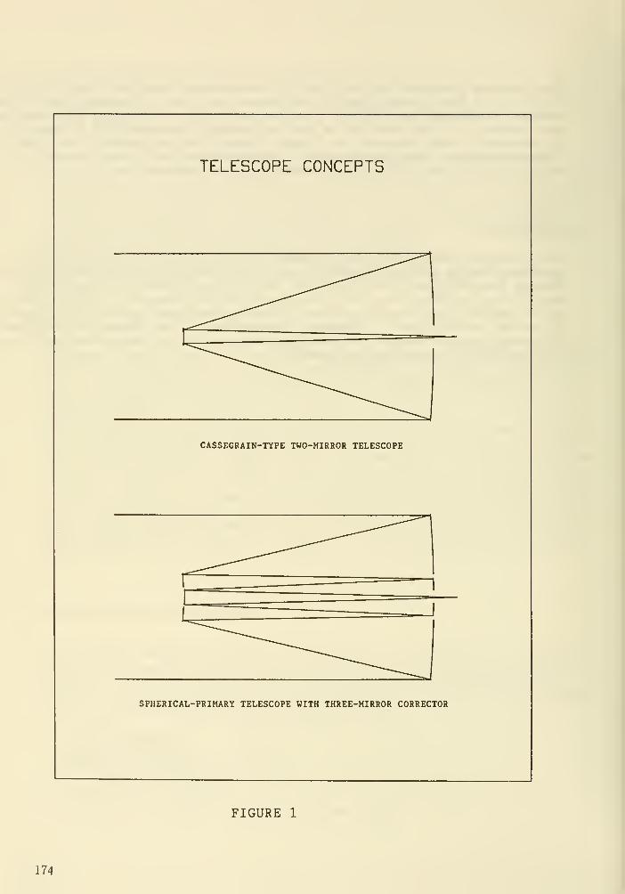
TELESCOPE CONCEPTS
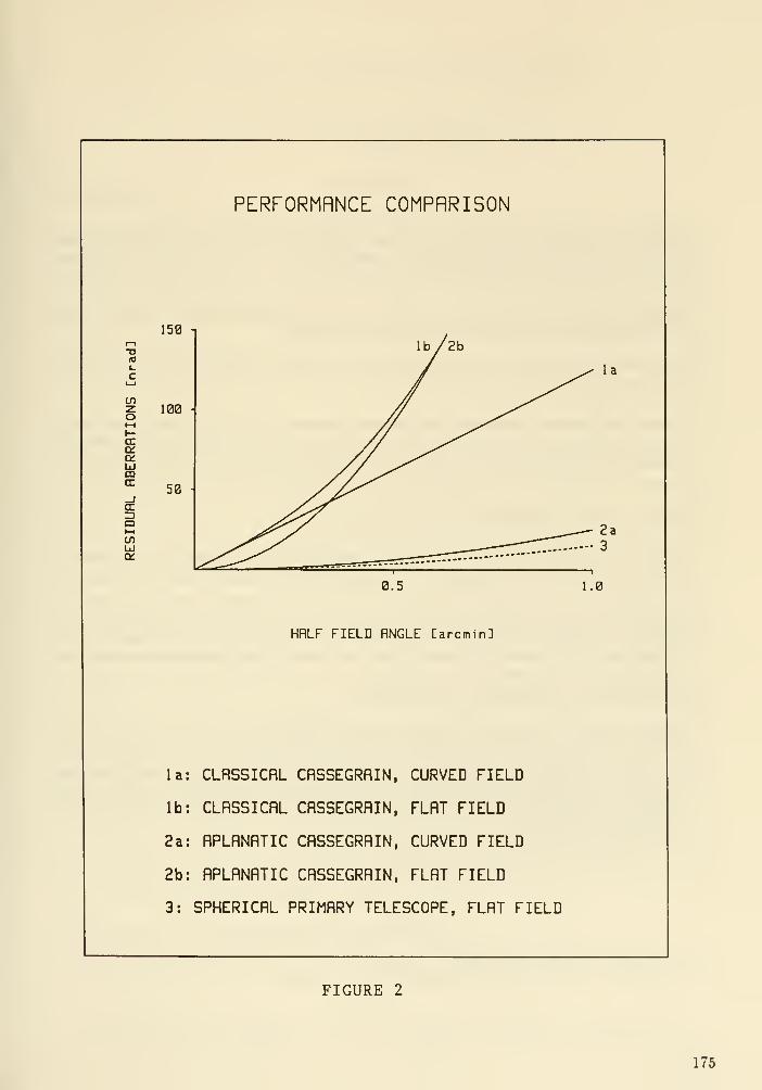

DISCUSSION
Nelson : For a Ritchey Chretien system, how large a field of view can be approximated by a plane?
The issue here is how large a single detector (in a mosaic) can be and still be planar. The individual
detectors can be laid out to approximate the curved focal plane.
Korsch : It depends on the actual design parameters. For our example, the residual aberrations reach
about pixel size (10 fiia) at the edges of a 1 arcmin diameter field.
Bely : Your proposed design includes 4 reflecting surfaces. Could you comment on the corresponding
loss of throughput?
Korsch : This question is difficult to answer, because it depends on too many factors, such as coating
materials, coating process, aging, etc. As an example, according to Action Research data, the efficiency,
using a UV coating optimized for 250-360 nm (Ag and Mg F2), drops to 64% after two reflections at
150 nm.
Rehfield : Have you considered three mirror astigmat designs?
Korsch : A three-mirror telescope with an aspheric primary could meet the performance requirements.
However, it seems that a spherical primary with a two mirror corrector cannot be corrected well enough.
Dlingworth: You have concentrated on a flat focal plane and noted that the field is quite limited
with a curved focal plane. However, I do not feel that a curved focal plane is necessarily a major
disadvantage. The instruments could accommodate such a curved focal plane and will generally have
interniil relay optics. I doubt also that we would try to have such a large magnification in one element.
The structural requirements appear to be too large.
Korsch : There are certainly more important considerations than a flat focal plane as I have tried to
point out in the paper. However, flatness of the field, at least over the area of an individual detector
array (1/2 to 1 arcminute), may be required. The concern about a large secondary magnification is as
familiar as it is unjustified. Interestingly enough, nobody is ever concerned about an afocal telescope
which has an infinite secondary magnification. It is the vertex curvature that can cause fabrication
and adjustment difficulties.
176
The Lunar Configurable Array Telescope (LCAT)
Aden B. Meinel and Marjorie P. Meinel*
Jet Propulsion Laboratory
Introduction
The desire for a much larger space telescope than HST by astronomers is clearly
demonstrated by the attendance at this Workshop. The reality is that a much larger
space telescope than the HST collides with cost scaling reality. Coupled with this reality
is the fact that any multi-billion dollar science project must have broad-based support from
the science community and solid political support at both Presidential and Congressional
levels. The HST Successor is certainly in the same multi-billion dollar class as the Super
Collider of the physics community, a project that has finally achieved the broad support
base necessary for funding to follow. Advocacy of a bigger HST on the general grounds
that 'bigger is better' will not be sufficient. A new concept needs to be developed that
clearly diverges from scaling up of a traditional HST-type space telescope. With these
realities in mind we have a few comments regarding the nature of a possible space telescope
that may depart from what the organizers of this Workshop had in mind.
The national goal declared by the President is Space Station, the Moon and Mars, in
that order. Space Station is a potential location where a large system could be assembled
prior to being sent into a high orbit. It is not a desirable environment for a large space
telescope. Mars is not relevant as an observatory site. The Moon is very relevant for
reasons we will address. Our comments are based on the premise of a permanent Lunar
Outpost.
One of the main arguments for a lunar telescope is a degree of permanency, that is,
as long as a Lunar Outpost is maintained. In contrast, the relatively short lifetime of an
orbiting telescope is a disadvantage, especially as a cost penalty. Access to a telescope in
a 100,000 km orbit for refurbishment and resupply is a major problem with no solution
in the present NASA planning.
A telescope in conjunction with a Lunar Outpost means the possibility for continual
upgrading or modifying the telescope to meet changing science objectives. The two main
technical disadvantages of the Moon are i) its gravity field and ii) direct Sun and Earth
light. The gravity term is manageable. It also appears to be feasible to shield the telescope
from direct sun and Earth light and from scattering from nearby lunar terrain. Thermal
disturbances to the telescope also appear to be manageable by proper shielding, enabling
the telescope to become as cold as if it were at a lunar pole crater. If these conditions are
met, the telescope could be at a logistically convenient location near the Lunar Outpost.
We want to address a concept that is significantly different from those presented in
the preliminary communications from Garth Illingworth in order to help fill in the matrix
of possibilities. This option, moreover, is of special interest to JPL and could be an area
where JPL can contribute in future studies.
The Lunar Configurable Array Telescope (LCAT)
The lunar telescope could well be the optical analogue of the VLA: the Lunar Con-
figurable Array Telescope (LCAT). In tight clustering, similar to the MMT, it would
* The authors were unable to attend the meeting. This paper was read by J. Breckinridge who also
answered questions on their behalf.
177
produce a tight diffraction image suitable for feeding a high resolution image into the
entrance aperture of analytical instrumentation. In dilute array it could become an in-
terferometer of immense resolution capability through image reconstruction. JPL has
prepared reports on the performance capabilities of lunar imaging interferometers that
can be supplied upon request.
An LCAT is also a possibility for a very large space telescope operating in high Earth
orbit. Here the problem is one of telescope lifetime compared to the usefulness of a given
configuration and the number of weeks or months that a given configuration would be
maintained. Configuration changes for VLA are scheduled months in advance to meet the
science objectives of many astronomers.
This scheduling strategy is not appropriate for an orbital system, but it is for a lunar
system. If the orbital system has a lifetime of only 5-10 years, configuration changes
would be limited because of the intense demand for observation time. A full 10-year
program could be developed for the array in its densest configuration. Similarly, a full
program could be developed for the array in its interferometric configurations. The system
lifetime would simply be too short to meet its potential for serving a broadest astronomical
community. Not so for a lunar-based LCAT.
In our concept the most attractive aspect of LCAT is that the array consists of
modest-sized fully-independent modules. This means that lunar-based astronomy could
begin as soon as the first module is delivered to the Lunar Outpost. The cost scaling law
is favorable, the political hurdle minimized, time to first light minimized, and industry
assured of a production run sufficient to attract interest and effective support.
The optimum module size is clearly one that can be carried, fully assembled, in a
single transport vehicle. This means a mirror that is the order of 2.4 m diameter, a size
that is attractive because of existing industrial fabrication facilities and the baseline of
experience to date with modules of this size. The alternative, if a large module is desired,
is to at least have major subsystems fully assembled to minimize final assembly at the
lunar base. One could foresee that there might be a manufacturing capability in the
4-meter size class, but the module cost then would be considerably higher. The answer
as to whether a 2.4-m module would be sufficiently large can readily be had by modeling
procedures.
While the size we are proposing for each module is that of the HST, we do not propose
that the module will either look or cost like the HST. The LCAT module would be
much more compact and not have the expensive spacecraft modules necessary for orbital
operation. The LCAT module would have the basic parts of any terrestrial telescope,
with the beam combining module a separate subsystem delivered as a complete unit. The
goal would be an LCAT module small enough and light weight enough that it can be
delivered as space is available in the manifest.
Some of the main technical issues which need to be addressed are examined below.
Field of view. The field of view of the MMT is limited to a few arcmin by the size of
the facets on the six-sided beam combiner. If a wider field is desired, a prime focus
single mirror combiner can be used. It is still limited to a field of about 10 arcmin,
but for a large telescope this size field is quite useful.
Added reflections. The beam combiner and path length compensation add at least
three reflections. This can be serious for wavelengths below 0.2 fim. One is then
caught between the desire on the one hand for the highest resolution, meaning an
array of apertures rather than a single aperture, and on the other hand by a longer
178

integration time. For the most extreme ultraviolet it would probably be preferable to
operate the array as singles, and consequently at the resolution provided by a single.
Path length compensation. Path length compensation of a lunar array is small com-
pared to that for an imaging interferometer on Earth. The rate at which the path
length compensation system operates is small but over a much larger total path-
length change if a kilometer-sized array is used. An array like that proposed for
project ALOHA by Labeyrie, where mobile modules move so as to keep path lengths
constant, is a possible option. Further engineering analysis would be needed to deter-
mine if the ALOHA concept is a practical option for a lunar system. Demonstration
of ALOHA on Earth is clearly a necessary precursor.
Polarization. The plane of polarization must be maintained throughout the reflections
in the path length compensator / beam combiner optics; otherwise the diffraction
pattern of the array will be compromised.
Diffraction / MTF effects. The diffraction pattern formed by an array of discrete
apertures results in energy being distributed into an array of secondary maxima sur-
rounding the central maximum. The cleanest diffraction pattern is clearly that of
a single unobscured aperture. As the apertures are separated the number and in-
tensity of these secondary maxima increase. For a non-redundant array the central
maximum is at maximum sharpness and resolution but at minimum central spike
intensity. What is not always appreciated is the seriousness of the efi'ect of such an
array pattern on the secondary maxima. Both the number and intensity total of the
secondary maxima are maximized. This situation is very bad if one wants to feed an
analytical instrument or record a direct image.
We feel that the LCAT concept should be given study attention edong with the more
conventional options for both orbital and lunar telescopes. This study should first be
from a systems point of view. This would be followed by addressing technical issues such
as the performance of LCAT in its densest clustering as well as for various configurations
required for typical science objectives. It is easy to talk about beam combining. The
real problems arise when one is faced with actually building a working system. These
practical engineering aspects of beam combining mean that good concepts need to be
developed and then analyzed. One objective of such a study should be to define precursor
experiments that could be done on Earth to show that critical milestones can be met.
There is an interesting compromise between a single large aperture telescope and an
interferometer that still makes use of the modular concept: A fixed, co-mounted cluster
of seven modules, much like the MMT, plus outlying modules that would constitute the
configurable interferometric array. The co- mounted cluster of seven would avoid path
length compensation, give a reasonably tight diffraction pattern, and still have the cost
and logistical advantages of modules that we discussed above.
Current related projects at JPL are addressing construction of a large imaging inter-
ferometer at a terrestrial site, location TBD (supported by the U.S. Navy), and design of
an orbiting imaging interferometer of fixed baseline, supported by JPL funding.
Acknowledgements
The research described in this paper was earned out by the Jet Propulsion Laboratory,
California Institute of Technology, under a contract with the National Aeronautics and
Space Administration.
179

Artist concept of the Lunar Configurable Array Telescope (LCAT)
Standardized modules are delivered to Lunar Outpost as manifest permits. The modules are config-
ured as they become available into a Large Aperture MMT with two or more configurable interferometric
modules. Astronomy begins as soon as first module is de livered. The science objectives are similar to
those of the NGST.
Advantages of lunar siting include: long operating lifetime, support from Lunar Outpost, vacuum
environment, very low tracking rates, and ability to be reconfigured as science programs require.
180
DISCUSSION
Woolf Recall that yesterday Roger Angel showed that while we are replacing the MMT with a single
large aperture, with Columbus we are building a new MMT. The MMT concept is only appropriate if
you have already started with the largest filled aperture that is possible. And if you want the same
point source sensitivity as a 16 meter with thinly spread 4 m apertures, you need 256 of them.
Rolan : Extending the comment that Nick Woolf made, - as segment diameters rise, the full facesheet
costs may drop, but one finds that reaction structure costs climb. (As diameters go up, bending rises
by segment size to the 4th power; this has to be bought back with thickness, and thus the substrate
cost can climb to oiTset pure faceplate based conclusions.) Thus, the optimum cost point for "5-tier"
construction may be < 8 m, especially when possible breakage is considered. Conversely, for "3-tier"
designs (which are probably the preferred way to go), larger may be better.
Breckmridge: Yes, and it's certain that we need to do sufficient phase A studies to really let us get at
some of these issues. I believe that NASA must have a much more aggressive Phase A system study
than we had for EST. This is essential to: (i) identify trades between filled aperture and interferometry
in terms of science payoffs; (ii) constrain cost; (iii) monitor technology development activities. The
more money that is put up front in studies and analyses the cheaper the whole telescope is going to
be (..APPLAUSE!!..).
niingworth: Let me make a point that is related to this discussion. There have been several workshops
over the past few years where a rather rosy view has been taken about the potential of interferometry.
There have been many scientists who have become concerned that we were starting down a path that
was too narrowly defined in its technical focus without a clear understanding of the scientific goals of
the astronomical community. The perspective has now become more sophisticated and an appreciation
has developed that these approaches are complementary. If one looks at the observational phase space,
the multiparameter phase space, there are regions which are optimally tackled by interferometry, and
there are regions that are optimally tackled by large fiUed-aperture systems. The overlap is a grey
area, which needs to be fleshed out scientifically and technically. I see this workshop as one of the first
steps in this process.
181

Large Optical Fabrication Considerations
and Speculation about the overall NGST Conilgiu'ation
Michael KrimPerkin- Elmer Corp.
Introduction
It had been recognized at Perkin-Elmer, as elsewhere, that the the ability to effi-
ciently produce optics in the eight to ten meter diameter class would be necessary for the
next generation of opticcil telescopes. Depending on the application, specifically whether
ground based or space based, these telescopes will have mirrors that, in general, are re-
spectively monolithic or segmented. We believe that it is not necessary to distinguish
between the two and that a manufacturing approach which is applicable to either type of
mirror architecture is within our reach. This paper describes such an approach and the
facility and equipment that would be required to implement it.
Since this conference is devoted to the science and engineering aspects of the Next
Generation Space Telescope (NGST) and not mirror manufacturing in general, we have
attempted to make our remarks about large mirror fabrication quite specific to that
project. In this regard we will present a design concept for the NGST*, the intent of which
is to provide the rationale for the selection of a particular mirror segmentation approach
as well as to provide sOme insight into other systems level design issues. Notable amongthese are the issues and considerations relating to system deployment and launch vehicle
space constraints, i.e. real-estate allocation, and other mechanical aspects of the design.
In any event it is exciting to speculate about what the large-scale design architecture of
the NGST might be. It is happily reminiscent of the work that we did in the early 1970's
when the configuration of the Hubble Space Telescope was first being "put to paper".
Telescope Conceptual Design
Why a Segmented Primary:
A concept for the overall architecture of the NGST is shown in Figure 1 where a six-
petal primary mirror, designed to facilitate automatic deployment in space without direct
astronaut assistance, is utilized. The system architecture shown in the figure was evolved
to meet the requirements and goals that were stated for the NGST. However, prior to
discussing the logic behind the design, certain key assumptions were made at the outset.
Firstly it was assumed that a launch vehicle sufficiently large to accomodate a monolithic,
or fully assembled segmented, 10m mirror would not exist in the USA's or anyone else's
inventory in the 2010 to 2015 era. While the Advanced Launch System (ALS) is generally
regarded as a 10m vehicle,it would not be large enough to accomodate a fully assembled
and erected 10m system. As shown in the inset, a 10m aperture telescope will have an
This paper was written prior to receiving the preliminary systems description and data package
prepared by Bely and Dlingworth. Any differences between what was assumed here and that data is
completely unintentional. The conceptual design described in this paper was based only on the material
contained in the announcement of the meeting and some (hopefully) educated guesses.
182
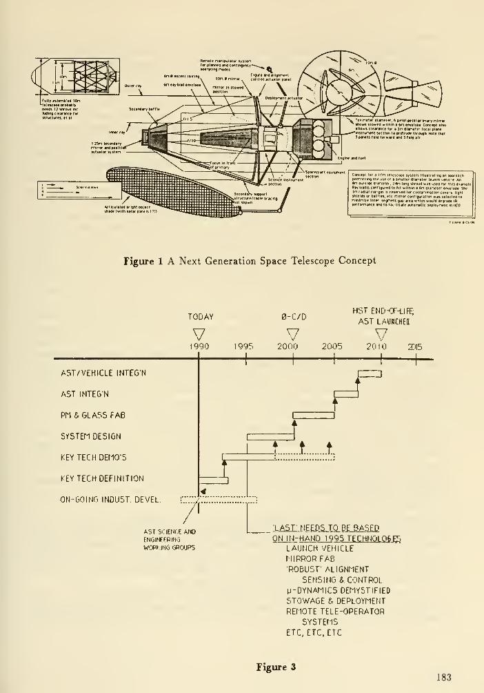
Rerwit nanipulaior sysienfor eivtMO antf conlinftncy--'
optrsitng noMs
n r\titr dlirtfl^. 6 priai pttal prinary nirror--Own ilOHfd wllMn • 6n Mtvvloe* Concrpi»• IIOHi clfM-WKi for > In dincttr ro<ii piww
^tnstrurttftt stctton to proirutft tnrougrt Nott tMt1 pvwis roio rerHVd sM 1 rsiQ art
Articulated Drignt odMiaot (with »ltr panels
Concept foi a H.>n telescope lysten iHuilraling an approscnpernmir>9 ine use or a mailer dianeier la^Kti vehicle Anin outside diineier. 24n long sivoud was used for tmj eianpiePayloadis conligured lo fit witnir a 6n diarteier envrlope ThtIn rtdldl oargm is reserved (or coManlnalion covers, lijni
sMeldi or baffles, etc nirror conf iquraiion was selected toninini/e Inter segrtenl gap area wnicri would deyadc inperrornjfKe artd to facilitate •ulonallc deploynenl iniCO
Figure 1 A Next Generation Space Telescope Concept
TODAY
y1990 1995
0-C/D
V2000
HSTEND-CF-LIF^
AST LAUMCHffl
2005V
2010 Xil5
AST/VEHICLE INTEG'N
AST INTEGN
PM & GLASS FAB
SrSTEM DESIGN
KEY TECH DEMO'S
KEY TECH DEFINITION
ON-GOING INDU5T DEVEL
r
/[
ASTSCIEfli E AHOENGirfEPlNG
WCPHNO '3R0IJPS
f4
rr...t. .t.
•LAST- NEEDS TO BE BASEDON IN-HAND 1995 TECHN0L06E5
LAUNCH VEHICLE
MIRROR FABROBUST' ALIGNMENT
SENSING & CONTROLM-DYNAT-IICS DEMVSTIFIEO
STOWAGE & DEPLOYMENTREMOTE TELE-OPERATOR
SYSTEMSETC, ETC, ETC
Figure 3
183

overall diameter of 11 or so meters when baffling, structures and other system elements
are accounted for. Adding shroud-to-structure clearances and making allowances for the
fairing structure itself adds perhaps another meter. This suggests that a 12m shroud
would be realistic expectation.
Secondly, a segmented 10m mirror system,including an integrating structure plus
position control actuators, is probably a significantly lighter than a monolith of the same
size. Presuming that a 10m sandwich mirror is designed such that the maximum bending
stress developed at a 7.5g quasi- static launch acceleration does not exceed a safe stress
limit of 2000 psi, it would weigh in the neighborhood of 50,000 lbs and be approximately
30 inches thick. This weight range is predicated on a family of mirror designs with 0.5 and
1 inch faceplates and a lOx areal density core. In Figure 2 we show the methodology used
to determine the weight and proportions of these mirrors. The stress equation shown in
that figure yields approximate answers only and is in no way intended as a substitute for
rigorous analysis. While this mirror doesn't imply a final optimized design, it is felt to
be representative of what might be achieved with a glass structure. This model further
assumes that the mirror is supported at 3 points near its periphery. Some stress reduction
can be achieved with supports at a 2/3'rd radius location. The center deflection at 7.5 g's
is on the order of 0.25 inches or about 9500 waves! It follows then that a (force) actuator
system and s reaction plate would be needed to compensate for "some" non-recoverable
launch strains. It follows also that an auxiliary multi-point launch support system would
need to be extremely stiff, and consequently heavy, if it were to be effective in limiting
deflections for such a mirror.
On the other hand, 3/4 of an inch glass distributed over a 10m diameter would weigh
only 7500 Ibi. However a 3/4 inch thick mirror segment in excess of 50 inches in diameter
will require more than a simple 3-point support system to limit stress levels to 2000 psi.
Therefore thin shell (meniscus) mirrors of this type would need to employ displacement
type actuators to couple it to a structurally efficient composite sandwich (or truss) support
structure. These are "stiff" actuators which directly impart a displacement to the mirror
as opposed to a "60ft" actuator such as employed on the HST which apply a force field
to the mirror. This is an important but subtle difference. The idea here is to "....use
structures for what structures do best and use mirrors as mirrors".
The sandwich mirror will require fewer but more powerful actuators than the thin
meniscus mirrors. Both approaches will require reaction , i.e. support, structures. Qual-
itatively the weight of the actuator systems will be "a wash", at least to first order. In
that case, the segmented meniscus approach could save about 25,000 lbs over a monolithic
approach. The additional weight of the deployment mechanisms and possibly a robotic
arm for teleoperator- assisted erection will still result in a positive weight advantage for
the segmented approach.
Finally one might question the technical and economic feasibility of producing a 10m
diameter lightweighted (sandwich) mirror blank from a low expansion material such as
Zerodur or Coming's ULE within the next several decades . For these reasons, the ability
to efficiently produce a segmented primary mirror appears to be an important technology
for any NGST concept. Implicit in this is also the technology needed to ensure the
coalignment to fractional micron tolerances of the segments.
As tempting as it is to dismiss orbital assembly as something that could be accom-
plished by suited astronauts on a space station, the dependence of the NGST on the
availability of such a resource was avoided. Even if it were assembled in low earth orbit
184
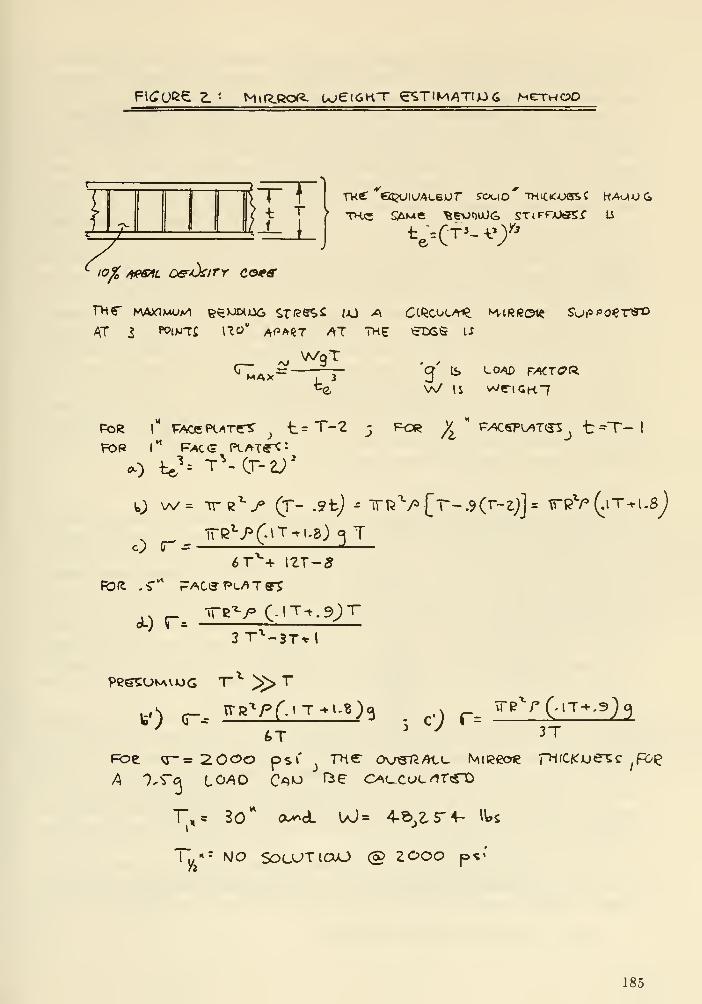
FK^ORC Z ' M\R.ROR. UjeiGKT eSTlMATIjJc; MeTHCPO
Elofo /tpa^fi Off<kiTr co^s
rnr nvaxix^z/i &e>Jwo6 srf?esi jjo ^a ckscocai^ kirroi^ suf=po€r<yo
^T S WtVTi I'Jy" A<>AiiT /^T THE etiGS li
MAX W vv/ IS we"iGK"7
Fo«? 1** FAceP(./^Te^ ^ t=T-2 _5 for ^ ' p^^spi^tcj^^ t^T-
I
FOP l"^ ^M.<= PLAT«-^:
O (T- ^^ -^
—
FOft .-r'^ PAC(3-1*i./>Tff5
dL) r-
^T + 12T-5
3T'^-3T*I
6T 3T
Foe q-= 2.0OO pst'_j
mer ov«t^/h,(_ MiRcoie pi(C«:xje^c ^p>i^
r,c 30** cx>^dL UJs 4-e>,ir+- IWj
y^
= MO SOL-UTICUO @ 2 000 p<'
185

( LEO ) and that there was an available orbit transfer vehicle (OTV), the boosting of a
fully assembled, relatively frail and flexible NGST represents a major controls, contam-
ination avoidance, and structural dynamics challenge. Therefore we opted to configure
the design to be automatically deployed in the specified high earth orbit (HEO) and to
require only a single launch to achieve operational status. Finally, it is assumed that it
would be desirable to achieve an operational date of about 2010 for the NGST. That is
consistent with the HST's 15 year lifetime. Completing the NGST within 20 or 25 years
from now implies that the technologies that will be used for it's design and construction
are no more than extensions of what can be accomplished today, particularly with regard
to materials. In fact it might be stated that the NGST cannot afford to use anything
later than 1995 technology. We show this in Figure 3 where an attempt at a development
schedule is presented. This schedule tacitly implies therefore that the primary mirror will
be glass, such as Zerodur of Corning ULE, although the rapid emergence of new mirror
materials such as silicon carbide may alter this conclusion in the near future.
A few comments about the concept drawing need to be made here. To a large extent,
the drawing began with an outline drawing of the assumed launch vehicle which defined
the envelope for the stowed NGST. An 8m outside diameter ascent fairing with a 7mdiameter available for the payload was assumed. While such a vehicle does not exist
today, it is within the range of capabilities that are being considered by the Air Force and
NASA. For the purposes of this paper, volume constraints were considered to be morecritical than weight. The ability to stow a 10m system in a 7m payload envelope and
then automatically deploy it places far greater demands on on the resourcefullness of the
designers than weight, at least in my opinion.
Primary Mirror Segmentation:
Segmentation concepts for primary mirrors encompass the (nearly) hexagonal shapes
employed by the Keck and LDR designs, multi-row trapezoidal concepts often favored by
metrologists since each row or circle contains identical facets but which are wasteful of
material, and petals such as we are suggesting for the NGST. The principal motivation
for the petal approach where each petal is in itself a monolithic segment is infra-red
operation. To minimize self-emission or thermal noise arising from the telescope, the total
area of non-reflecting surface between the mirror segments needs to be minimized. This
is accomplished with the petal approach. A monolithic individual segments which might
be pre-assemble and aligned on earth to take advantage of the deployment advantages of
the petal configuration but the idea of reducing gap area between the segments would be
defeated.
A six-petal approach was selected because it represents the minimum number of petals
that can be stowed within the assumed 7m diameter cargo bay or ascent fairing (shroud)
payload envelope. This was illustrated in Figure 1 where three petals are folded forward
and three back. The superscribed circle enclosing the segments is 6m leaving margin
between the assumed 7m allowable payload envelope. At this stage of the concept, this
margin needs to be reserved for mirror support structures, thermal control surfaces, anddeployment mechanisms. The inscribed circle is 3m which is sufficient for the telescope
instrument science instrument.
Another petal approaches such as a "vegetable steamer", shown in Figure 4, in which
all the petals are folded in one direction but overlap in sort of a spiral fashion was rejected
because it forced the petal assemblies to be too thin for practical applications. Another
186
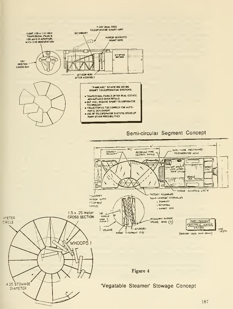
EIGHT 126 » 110 INCH
TRAPCrOIOAL PA^iELS
FOR AN a-n APERTURE
WITH Jl« OBSCURATION
7-DOf DUAl. nODE
TELEOPERATOfi SMART-ARM
MIRROR SEBrtENTS
MOUNT HERE
JETISONKREAFTER ASSEMBLY
-PAMCAKE- STACKIHE USING
SnAKT TELtOPtRATOR STSTEHS
• TRAPEZOIDAL PANELS OFFER REAL -ESTATE
ADVAKTAGES OVER PETALS
BUT WILL REQUIRE SMART TELEOPERATOR
TECHMOLOGYTRAJECTORIES TOO COMPLEX FOR Ain-0-
MATIC DEPLOYMENT• USE OF TELEOPERATOR SYSTEMS OPENS UP
MANY OTHER POSSIBILITIES
Semi-circular Segment Concept
-METER
CIRCLE
1 .5 X .25 meter -^
CROSS SECTION »""'-«
1 youp^ttitsie '-toPfoeT erf (raoojco US06 Mi«c-oeA»'J
4 25 STOWAGEDIAMETER
Figure 4
'Vegatable Steamer' Stowage Concept
187

approach where the mirror was divided into only two segments, split along a diameter
and stowed on either side of the central telescope structure, also shown in Figure 4,
was considered as way of minimizing the inter-segment gap area. While it has manyadvantages from a mirror producibility and performance aspect, the lack of rotational
symnetry was judged to be a disadvantage from an automatic deployment aspect. As
shown in that figure, such an approach would include a robotic arm to 'maneuver' the
segments and other system elements into position as an alternative to the more fully
automatic deployment approach possible with the six-petal configuration.
Figure Sensing and Control:
The critical difference between segmented and monolithic mirrors is that the former
requires that each segmented be generated and figured to an absolute radius of curvature
while for a monolith, the radius of curvature only needs to fall within some nominal range
defined (primarily) by the adjustment range of the secondary mirror. A rough estimate of
overall wavefront error as a function of the difference in the radius of curvature between
segments can be obtained from the equation
_ 1 d^AR
where d is the smallest segment dimension and R is the nominal radius of curvature. Theprecision of i?, expressed as AR/R is on the order of 310~^ for a wavefront error of a
twentieth wave (rms) and for a nominal segment size of 2m and a radius of curvature
of 30m. This is equivalent to a gross saggita tolerance of 0.04 micrometers or about
1 fourteenth of a wave. Clearly this degree of precision is difficult, if not prohibitively
costly (my opinion), to achieve if the segments were individually produced and/or if
there were no means for adjusting curvature after the segments were actually completed.
The four mirror telescope design advocated by Meinel and the LDR community is an
elegant means of correcting radius of curvature errors arising from manufacture. For
the NGST however, we felt that the additional two reflections imposed by the tertiary
and quaternary mirrors might be too expensive from a throughput aspect in the short
end of the operating spectrum. A more appropriate solution for this application wethought would be the use of shape (figure) control actuators which physically bend the
segments to the correct curvature,if required, to correct for manufacturing errors. Thefigure control system, whether used directly on the primary mirror or on an image of it
on a quaternary, also provides a correction capability for errors that might arise from
the large temperature change between the shop and orbital operation at the desired 100
degrees Kelvin. Of particular concern is the effect of this spatially uniform temperature
change on any CTE anisotropy that might (will) be present in the segment substrate. Wewill take advantage of the ability of the figure control system to correct low frequency
aberrations and thereby relax the manufacturing tolerances in this range to about a half
wave rms. The presumption here is that a properly designed actuator system can provide
a wave of correction, at least in the long spatial frequency domain. In the mid- spatial
frequency regime, beyond the (presumed) correction capability of the actuator system,
the as-manufactured figure quality will be on the order of 0.01 waves. As with the Hubble
Space Telescope (HST), our optics manufacturing approach is based on the use of small
tools operating at a uniform and constant interface pressure with material removal being
proportional to velocity of the tool path at any given point. This is accomplished at
Perkin-Elmer with a machine referred to as the Computer Controled Polisher (CCP).
188

The concept of a CCP capable of figuring a 10m mirror will be described later in this
paper, after the architecture discussions are completed.
The ability to compensate for long spatial frequency errors with actuators mitigates
against the need for inherently rigid mirror segments. In fact, rigidity can be a detriment
in the design of a figure control system (in certain instances). Provided that figure errors
in those spatial frequencies equal to or shorter than the span between three (theoretically
two) actuators are within acceptable limits (0.01 waves rms), the low spatial frequency
errors can be relatively large, several waves is not unreasonable although we have not yet
quantitatively explored just how inaccurate one could allow the optic to be before the
sensing and control system becomes an impractical theoretical exercise.
It is conceivable therefore that the substrate could be a relatively thin sheet of ma-
terial, a 25mm (1 inch) for arguments sake, provided of course that it can be generated
and figured. It is (well) beyond the scope of this paper to address the trades relating
thickness, actuator density, sensing and control system complexity, structural integrity,
weight, inherent reliabiity, and so on. Suffice for this discussion, the ability to generate,
figure, and polish extraordinarily thin substrates is an important consideration in the
manufacture of a NGST type mirror.
Other Interesting Speculations About the Concept: It was assumed that at least a
dual focal length capability, for many of the same reasons this is the norm with terrestrial
telescopes, would be desired. For illustrative purposes it was assumed that the visible and
infrared final focal ratios were 10 and 20 respectively and that the primary mirror would
be f/1.5. Focal ratios (f/no's) greater than 20 were not considered for NGST because of
the size related and exponentially increasing vibration and structural sensitivities. Final
focal ratio-to-detector matching is as usual, an instrument responsibility. These choices
were not based on any quantitative trades or analyses. An f/1.5 primary was judged to be
as fast as one could go optically and still achieve a 20 or so arc minute total field of view.
The selection of an f/10 visible and an f/20 IR focal ratios offers the ability to minimize
the size of the secondary mirror to reduce self emission for IR operation. This could be
at the expense of having two secondaries that could automatically be interchanged. This
is probably a disadvantage from a weight, dynamics, and failure potential aspect. Several
otlier more attractive approaches for achieving a dual focal length capability could be
considered including the use of common f/10 fore-optics with the visible focal clearance
and employ a tertiary to achieve a 2x final magnification as well as to provide an exit
pupil for the location of a cold stop.
Unlike the HST, where a 3m superscribed circle enveloped the instrument package, it
may not be necessary to locate the NGST's final focus behind the primary. Presuming
that a 3m diameter instrument section is still reasonable, then the instrument section
might be allowed to pass through a central hole in the mirror at the expense of a linear
obscuration ration of 0.3. A 1.25m secondary with a magnification of 6.6 would produce
an f/10 image which comes to focus approximately 0.6m ahead of the primary. This is
what is shown in the conceptual drawing.
Regardless of what form the final optical design might take, the secondary mirror needs
to be supported by a structure which, from an idealistic IR performance standpoint, should
not introduce any obscuration in object space and must not introduce any obstruction in
(convergent) image space. An off-axis system would fulfil these desires. A structure such
as the HST secondary mirror support truss would be a good practical compromise. While
the the obscuration from the thin spiders legs are in object space, the rest of the structure
189

is totally outside of the optical envelope. However, for all intents and purposes, a 10mcylindrical truss such like the HST is a non-solution for the NGST, it is not amenable
to automatic deployment. One attempt at a solution for a deployable secondary mirror
support structure which doesn't intrude into image space is illustrated in the concept
drawing. It consists (very conceptually) of an arrangement of telescoping tubes and
rotary deployment actuators which can be stowed within the 7m payload envelope. As
shown in the drawing, the erected truss will not intrude into image space, meeting the
self-imposed (inflicted?) goal for IR performance.
Baffling:
Bright object baffling, i.e. the earth, sun, and moon, is a persistent problem for giant,
space deployable telescopes. The use of a positionable bright object blocking screen might
prove to be a more easily implemented solution, albeit with (potentially severe) opera-
tional constraints. While on the subject of large distributed surfaces, the concept drawing
does not show any solar arrays. Hopefully by the time NGST becomes operational com-
pact power sources such as nuclear or radioisotope generators become politically as well
as technically acceptable. The cumulative effect of submicron micrometeoroid impacts on
the surface of the primary mirror is an issue that requires further evaluation. A baffle en-
closure, even one composed of several layers of multi-layer insulation (MLI), can provide
some protection against this source of degradation.
So much for thoughts and speculations about what the NGST might look like and
why. Now I shall describe how the mirror described in the concept might actually be
produced.
Large Mirror Manufacturing options
As we stated at the beginning of this paper, Perkin-Elmer along with others in the
field, have been exploring alternative ways of producing optics in the 8 to 10 meter
size range. Our experience lies with the successful application of small tools, the CCPdescribed earlier, and we can extend that technology from the 90'th wave, 2.4m HSTprimary to the the 10m NGST. All of the technology to accomplish this facility scale-up
is currently in place and we believe that such a mirror could be completed in five years,
including the production of the blank by Corning or Schott and the parallel construction
of the building and the fabrication of the metrology and polishing equipment. Subsequent
mirrors of that size, if there are any and we hope that there will be, could be figured at the
rate of one every two years in that facility. The model of such an optical manufacturing
facility is shown in Figure 5 and will be described more fully later.
Segment Manufacture:
In addition to the basic issue of scaling up our optical shop to accomodate 8 to 10mHST type (monolithic) mirrors, the question of radius of curvature matching of individual
segments to the kind of precision described earlier has been also been addressed at Perkin-
Elmer. Making matched segments, one at a time, has successfully been accomplished
under government contract. In this instance the segments were spheres, approximately
Im in diameter with a focal length of 5m (as I recall). While successful, this approach is
190
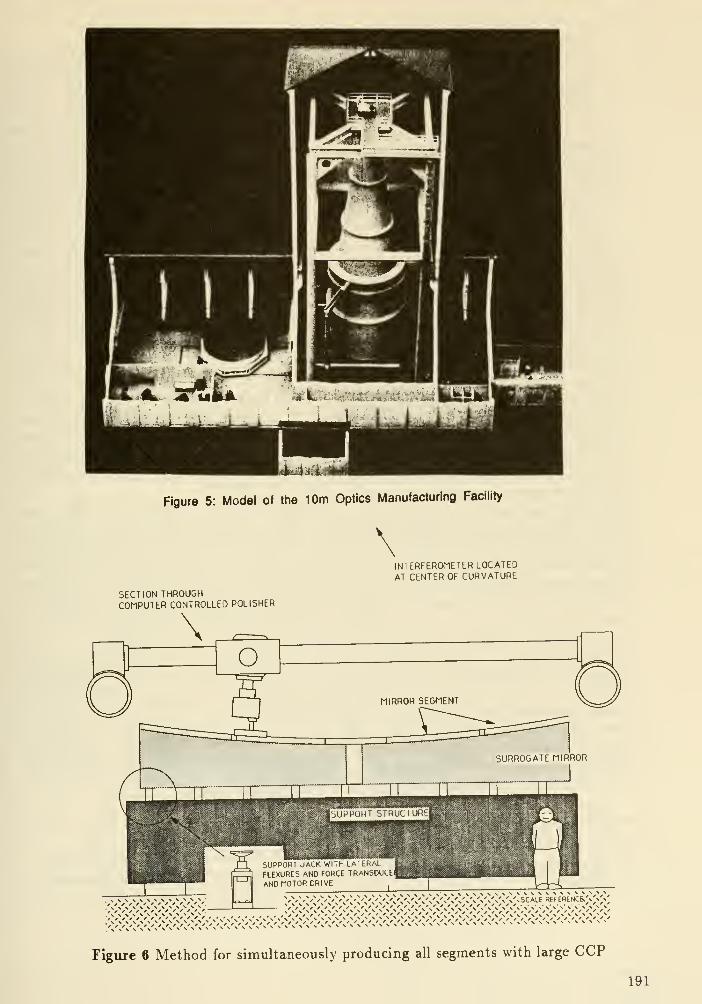
Figure 5: Model of the 10m Optics Manufacturing Facility
INTERFEROMETER LOCATEDAT CENTER OF CURVATURE
SECTION THROUGHCOMPUTER CONTROLLED POLISHER
Figure 6 Method for simultaneously producing all segments with large CCP
191

extremely costly in terms of schedule. As described earlier, curvatures can be adjusted
to some extent with actuators, or as in the case of Keck, with preset "coercers", i.e.
a "set and forget" actuator. Or at least that's what I think is being done. On another
program that we were associated with, the Large Deployable Reflector (LDR), the concept
of "semi-replication" was evolved where a graphite tool was used as a master for molding
thin quartz substrates to a common radius of curvature. In this instance quartz was
selected because of it's superior homogeneity. This was an important factor since the
temperature change between fabrication and operation was several hundred degrees (F)
and the AR/R precision had to be preserved. This process was subsequently demonstrated
in a joint Perkin- Elmer/Hereaus program, under the DARPA umbrella program called
Rapid Optical Fabrication Techniques (ROFT). In another program sponsored by NASA-Lewis, we successfully laminated thin glass sheets to (nearly) matching CTE (coefficient
of thermal expansion) composite substrates preformed to a spherical surface. These two
programs are mentioned only for completeness since enormous material and process scale-
up problems would need to be solved before they could even be considered as a candidate
for the NGST mirror. From here on we shall confine our discussion to glass mirrors, albeit
unusually thin by present standards.
The ability of the CCP to be scaled up to 10m sizes begs the question, "Why not
temporarily attach all the segments to a 10m tooling plate and generate them all at once?".
In principal, the concept is as illustrated in Figure 6. The idea here is to "fool" the CCPand/or the optical shop into thinking that they are working on a monolith. In this mannerit is believed that all of the segments will have the correct curvatures, eliminating the
AR/R concern described earlier. This is really an extension of the technique developed byDr. Robert Leighton of the California Institute of Technology for the rapid and accurate
manufacture of 10m class sub-millimeter aluminum reflectors.
There are three issues that must be resolved for such a technique to work: what
material should the tooling plate be made of; how are the segment substrates attached to
the tooling plate; and what will be the extent of sleeking or other gap related 'damage' and
how can it be controlled. Ideally the tooling plate would look very much like a relatively
thick mirror and be constructed from the same material as the segments. The segments,
presuming that they are constant thickness elements of a meniscus, would be attached to
the concave front surface of the tooling plate. This front surface would be generated to a
sphere whose radius of curvature matched the back surface of the segments.
In addition to the obvious choice of ULE or Zerodur for the tooling plate, a muchlower cost and more readily available material, slip cast silica, has merit. Slip cast silica,
as produced by the the Cerodyne Corporation, is used for high temperature tooling by the
automotive and aircraft industries. It is cast, as implied by the name, from a fused silica
slurry which may optionally contain a pebble sized fused silica aggregate which improves
its strength and reduces shrinkage during the drying process. It is fired at a relatively
low temperature (1100 degrees C) after casting to produce a stable, structurally sound
shape which is about 95% as dense as the parent material. It can (probably) be cast over
styrofoam or similar blocks to achieve for lightweighting if deemed necessary.
The key attributes for the attachment method to join the monolithic tooling plate
and the segments include:
a) the ability to fill (the small but inevitable) voids between the the mating surfaces
b) the ability to set up without shrinkage or other mechanisms for inducing strain in the
substrate
192
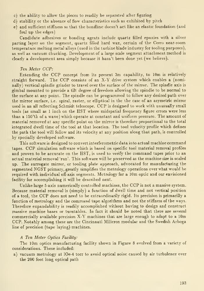
c) the ability to allow the pieces to readily be separated after figuring
d) stability or the absence of flow characteristics such as exhibited by pitch
e) and sufficient stiffness so that the bondline doesn't act like an elastic foundation (and
foul up the edges)
Candidate adhesives or bonding agents include quartz filled epoxies with a silver
parting layer on the segment, quartz filled hard wax, certain of the Cerro near-room
temperature melting metal alloys (used in the turbine blade industry for tooling purposes),
as well as vacuum chucking. Development of a large scale segment attachment method is
clearly a development area simply because it hasn't been done yet (we believe).
Ten Meter CCP:
Extending the CCP concept from its present 3m capability, to 10m is relatively
straight forward. The CCP consists of an X-Y drive system which enables a (nomi-
nally) vertical spindle grinder to travel over the surface of the mirror. The spindle axis is
gimba! mounted to provide a tilt degree of freedom allowing the spindle to be normal to
the surface at any point. The spindle can be programmed to follow any desired path over
the mirror surface, i.e. spiral, raster, or elliptical in the the case of an asymetric mirror
used in an all reflecting Schmidt telescope. CCP is designed to work with unusually small
tools (as small as 1 inch on the HST where midspatial frequency figure errors were less
than a 150'th of a wave) which operate at constant and uniform pressure. The amount of
material removed at any specific point on the mirror is therefore proportional to the total
integrated dwell time of the tool at that location. The tool velocity profile which defines
the path the tool will follow and its velocity at any position along that path, is controlled
by specially developed software.
This software is designed to convert interferometric data into actual machine commandtapes. CCP simulation software which is based on specific tool material removal profiles
and proven to be accurate on the HST, is used to verify the command tapes prior to an
actual material removal 'run'. This software will be preserved as the machine size is scaled
up. The surrogate mirror, or tooling plate approach, advocated for manufacturing the
segmented NGST primary, greatly simplifies the metrology operations over what would be
required with individual off-axis segments. Metrology for a 10m optic and our envisioned
facility for accomplishing it will be described next.
Unlike large 5-axis numerically controlled machines, the CCP is not a massive system.
Because material removal is (simply) a function of dwell time and not vertical position
of a tool, the CCP does not need to be extraordinarily rigid. Its precision is primarilly a
function of metrology and the command tape algorithms and not the stiffness of the ways.
Therefore expandability is readily accomplished without having to design and construct
massive machine bases or turntables. In fact it should be noted that there are several
commercially available precision X-Y machines that are large enough to adapt to a 10m
CCP. Notably among these are the Cincinnati Milicron modular and the Swedish Arboga
line of precision (tape laying) machines.
A Ten Meter Optics Facility:
The 10m optics manufacturing facility shown in Figure 8 evolved from a variety of
considerations. These included:
a) vacuum metrology at lOe-4 torr to avoid optical noise caused by air turbulence over
the 200 foot long optical path
193

b) insensitivity of the 100 foot high metrology tower to ambient seismic and acoustic
noise
c) in-situ metrology to minimize moving and handling the 60,000 lb surrogate mirror
(tooling plate and segment assembly) between figuring and metrology operations
d) the use of the CCP in a grinding mode to generate and aspherize the segments.
The ability of the CCP to operate with an abrasive wheel in addition to its morefamilar loose abrasive grinding and polishing mode reduces, or might possibly eliminate,
the need for either a 10m spherical generator or a precision grinder such as a Campbell.
More importantly this would eliminate the need for a large precision turntable. Roughshaping of the surrogate mirror (tooling blank) can (probably) be as 'sloppy' as 0.025
inches or 1000 waves and still be within the capabability envisioned for the CCP in a
wheel grinding mode. Since the CCP spindle path can follow almost any mathematically
describable shape, and since the spindle has a two axis tilt capability, by commanding it
to follow a series of concentric circular paths it can duplicate the kinematics of a classical
generator without a massive turntable. Following this quasi-generating operation with
a spiral path where the 'Z' direction or spindle axis is also programmed, the (nominal)
1mm or 0.040 inch of parabolization (or whatever) would also be accomplished without a
turntable (and without a large Draper).
In the next section, we will describe a facility concept which is based on the use of
this manufacturing approach with special emphasis on metrology.
Facility Concept:
As shown in Figure 8, the facility is essentially contained within a 150 foot high, 60
foot square tall building. This building is surrounded by a lower building which houses
engineering offices, a small machine shop, and an area for integrating the mirror assembly
with the shop support system. Because this operation requires high capacity overhead
cranes and because the cranes cannot pass by the metrology tower support columns, this
assembly operation is carried out in this support area. Once the integrated shop support
system and mirror are wheeled into the tower and firmly jacked into position, we do not
envision it to be moved again until after the final interferograms are completed.
Metrology Tower:
The metrology tower (Figure 9) is erected on a massive seismic mass, a 2000 ton
concrete foundation which 'floats' on a thick bed of crushed rock. This foundation is
separate from the foundation on which the rest of the building is constructed. Thetower itself is constructed from four Im diameter Ismm steel columns braced to each
other with a platform on top for the metrology equipment. To absolutely eliminate anyresonance amplification of the basic tower modes or to prevent the existance of local,
acoustically excited 'ringing' modes, the columns will be (partially) filled with gravel. Wehave designed the tower to have a I'st mode of 1.3 cps, including the non-structural massof the gravel. This is well above the noise spectra usualy associated with groundborne
'cultural' noise.
We had considered in-air (as was employed on the HST program), in helium, and in
vacuum metrology. Ultimately we came to the belief that a vacuum approach is the least
likely to provide 'regrets' during mirror fabrication. It is a conservative approach but
194

t>OL*C w*u. rXMUu' MUUIU
TXtS LEVtL OCCFT MkCN
BEHQ PERFOmO)
FUXMKALPI m-
I ^^^^^^^^^^^^Vti«^^^y;v;^^y
TD ELMNATC JCOuTTC COLMja
Figure 8 Section through the Metrology Tower
Figure 7 The Large Optics Facility as envisaged on the coast of Southern California
195

one which we have absolute confidence in. In addition to the extremely long optical path
length which itself might be a problem, stabilization times for HST metrology approached
6 to 8 hours in a closed chamber that had about tenth of the volume needed for the NGST.By eliminating the air, this stabilization time issue is eliminated. We believe that a mild
(10~^ torr) vacuum can be achieved in the same or even less time, containment vessel
would be required to contain the helium in any event. Rather than helium, it could be
'filled' with vacuum.
The vacuum chamber is suspended from the walls of the building and does not have
any direct mechanical connection with the seismic mass or with the metrology tower.
However the seismic block does serve as the lower closure for the chamber. We accomplish
this by constructing the vacuum tank with a cylindrical skirt at its lower end. During
figuring and polishing operations or when access to the mirror is needed, this skirt is
raised approximately 18 feet above the floor. During those metrology operations whenwe will require vacuum, the skirt is lowered to the floor and an inflatable rubber-like
seal will close the gap. As vacuum is increased, the skirt will be forced against the floor
compressing a compliant gasket on its lower end. The inflatable seal is a barrier against
the transmission of mechanical noise from the vacuum tank to the seismic mass and
consequently the metrology tower.
Metrology:
Full aperture phase measuring interferometery (PMI) will be used for the NGST. It
is important to note the inclusion of the words, 'full aperture'. We believe that working
at the full circular aperture with all of the segments in place on the surrogate mirror, and
consequently having symmetry about the optical axis, will lead to more accurate as well
as more rapid metrology. The ability to simultaneously figure all of the segments in place
is a distinct advantage of the CCP approach which is (conceptually) unlimited in size.
We investigated the effect of vibration on metrology accuracy, of particular interest
with the interferometer located approximatly 100 feet above the mirror. Using a PMImodulation frequency of 500 cps and assuming a (tentative) error allocation of 0.02 wavepeak to peak, we determined that 6 microns of lateral motion occurring at the tower's
natural frequency could be tolerated. This is equivalent to an acceleration response at
the end of the tower of 40 micro-g's (0.000040 g's). At the base of the tower whose
amplification at resonance will be extremely low as a result of the gravel fill, we estimated
that disturbance levels on the order of 15 to 20 micro-g's could be permitted.
Measurements made on the shop floor of our Danbury facility, which is within a thou-
sand yards of a major truck highway rarely exceeded 1.5 we do not believe that vibration
will be a problem, despite the 30m separation between the mirror and interferometer.
Unlike the HST where an all-reflective null corrector was employed, we believe that
this would be impractical for the NGST primary. The reason is that the mirrors would
have to be approximately 2m in diameter (or so I'm told by the optical designers). TheHST null corrector design cannot be simply scaled to the NGST because the f/No of the
latter is almost twice as 'fast' as the HST's 2.3. Suspending two 2m mirrors on metrology
mount systems whose precision needs to be equal to the HST mount is judged to be
an unacceptable and unnecessary risk. Therefore a refractive, or possibly a diffractive,
approach will be employed. Obviously different nul correctors will be used for coarse IRand for precision visible interferometry.
196
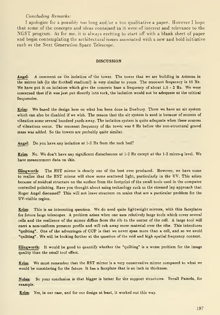
Concluding Remarks:
I apologize for a possibly too long and/or a too qualitative a paper. However I hope
that some of the concepts and ideas contained in it were of interest and relevance to the
NGST program. As for me, it is always exciting to start off with a blank sheet of paper
and begin contemplating the architectural issues associated with a new and bold initiative
such as the Next Generation Space Telescope.
DISCUSSION
Angel: A comment on the isolation of the tower. The tower that we are building in Arizona in
the mirror lab (in the football stadium!) is very similar to yours. The resonant frequency is 10 Hz.
We have put it on isolators which give the concrete base a frequency of about 1.5 - 2 Hz. We were
concerned that if it was just put directly into rock, the isolation would not be adequate at the critical
frequencies.
Krim: We based the design here on what has been done in Danbury. There we have an air system
which can also be disabled if we wish. The reason that the air system is used is because of sources of
vibration some severed hundred yards away. The isolation system is quite adequate when these sources
of vibrations occur. The resonant frequency of the tower was 6 Hz before the non-structural gravel
mass was added. So the towers are probably quite similar.
Angel: Do you have any isolation at 1-2 Hz from the rock bed?
Krim: No. We don't have any significant disturbances at 1-2 Hz except at the 1-2 micro-g level. Wehave measurement data on this.
mingworth: The HST mirror is clearly one of the best ever produced. However, we have come
to retdize that the HST mirror will show some scattered light, particularly in the UV. This arises
because of residual structure on the surface from the footprint of the small tools used in the computer
controlled polishing. Have you thought about using technology such as the stressed lap approach that
Roger Angel discussed? This will not leave structure on scales that are a particular problem for the
UV-visible region.
Krim: This is an interesting question. We do need quite lightweight mirrors, with thin faceplates
for future large telescopes. A problem arises when one uses relatively large tools which cover several
cells and the resilience of the mirror differs from the rib to the center of the cell. A large tool will
exert a non-uniform pressure profile and will rub away more material over the ribs. This introduces
"quilting". One of the advantages of CCP is that we never span more than a cell, and so we avoid
"quilting". We will be looking further at the question of the mid and high spatial frequency content.
mingworth: It would be good to quantify whether the "quilting" is a worse problem for the image
quality than the smtdl tool effect.
Krim: We must remember that the HST mirror is a very conservative mirror compared to what we
would be considering for the future. It has a faceplate that is an inch in thickness.
Nolan : So your conclusion is that bigger is better for the support structures. Recall Pamela, for
example.
Krim: Yes, in our case, and for our design at least, it worked out this way.
197

Large Segmented Optics Fabrication and Wavefront Control
J. Richard VyceLitton Itek Optical Systems
1.0 NGST Technological Perspective
As a space based optical system to be implemented and operated for years or decades
the NGST requires significant technological advances over the HST. Many, possibly all,
of these advances are under development. Several have been and are being done at Itek;
the scope of these efforts offers strong support for NGST feasibility.
Given the Workshop strawman NGST optical system of a segmented active primary
mirror in a cassegrain-type configuration, its generic optics control system (Fig.l) is likely
to follow those of other optical systems previously studied for various imaging and beamprojection applications. The earliest of the latter at Itek, interestingly, is a 30 meter
system (Fig.2) studied in 1975 for NASA Lewis as a laser projector for sending powerfrom low earth orbit to a lunar station.
The elements in Figure 1 lead to the natural separation of NGST technology re-
quirements into three distinct categories: the lightweight, deformable optical segments
comprising the 10-16 meter pnmary facesheets; the active primary structure and activa-
tion mechanism; and adaptive optics sensors and control elements for maintaining goodoptical wavefront quality and stable pointing. These three technologicjd areas will be
considered in that order in what follows.
2.0 Optical Fabrication
2.1 Keck Telescope Primary Optics
The 10 meter f/1.75 Keck primary, comprising 36-1.9 meter hexagonal segments at
6 different radii, represents one realistic NGST primary option. Indeed, there was the
reported 1988 announcement by the Soviet Academy of Sciences on their intention to
pursue a space telescope with segmented optics of a "design similar to the Keck telescope".
Keck Telescope mirror fabrication, involving maJcing the 36 segments plus a set of 6
spare segments, provides experience relevant to the NGST. Because the segments are a
reasonably thick 10 cm, it has been possible to make them utilizing the innovative stress
polishing technique. However, this is uidikely to be possible on the necessarily thinner
solid, or lightweighted, substrates of an NGST. Thus, Keck experience is relevant for
the magnitude of surfacing and for the final test technique, but not for the surfacing
technique. That is likely to be based on more general surfacing techniques such as Itek's
Computer Controlled Optical Surfacing (CCOS) described below. CCOS was originally
considered for final figuring on the Keck segments, but this was obviated by good stress
polishing results, and use of a "warping harness" in the segment whiffletree supports for
figure correction.
Steps in the Keck surfacing process are illustrated in Fig. 3. Stress polishing involves
applying precise bending loads to an appropriately supported circular substrate, so as to
deform the upper surface to the negative of the aspheric departure required in the finished
198

surface. After polishing with a large lap to the required spherical radius as measured with
a micro-inch bar profilometer each segment is unstressed and tested in the AutocoUimatingTest Facility (Fig. 4). It is then cut to hex shape, installed on its whiffletree mount, andremeasured in the ATF for warping harness adjustment. The ATF employs two movableflats and precise alignment metrology for autocollimation testing the segments in each of
the 6 raditd positions.
One infrequently encountered optical requirement, but a critical one in segmentedmirrors, is the need for precise radius match among segments. This is achieved through
measurement with the bar profilometer and radius control in polishing. The need for
radius determination in ATF testing added significantly to the difficulty of its metrology.
After some debugging problems the Keck segment fabrication process is proceeding
satisfactorily. Serial production is weU underway with several segments having been com-
pleted and fabrication time continuing to drop as experience accumulates.
2.2 Itek's CCOS (Computer Controlled Optical Surfacing) Process
CCOS process is aimed at surfacing general aspheric elements both centered and
off-axis with progressively greater efficiency. This process provides capability to manu-
facture 2 to 4-m aspheric mirrors in less than half the time needed with the conventional
technology. It is increasingly automated in its three major steps: figure generation, grind-
ing/polishing, and testing. CCOS is essentially the robotic emulation of a skilled optician
(Figs. 5,6) in which measured positive surface errors (bumps) determine rubbing com-
mands for a nutating lap whose polishing "influence function" is well characterized. As
with an optician, the process is iterative, but improving control of polishing parameters in
CCOS is increasing the degree to which errors are corrected in a polishing cycle, thereby
reducing the number of cycles and total surfacing time.
The mirror segment is first polished on an Arboga 5-axis machine which has circular
symmetry about an external center and hence the polishing pad works in circular arcs.
The pad is kept from rotating by a radius arm affixed at the center of symmetry.
To minimize the time between rubbing and testing, a CCOS machine is located ad-
jacent to an optical test chamber. The work piece, blocking body and stand are on an
air dolly which permits easy movement of that assembly between the machine and test
chamber.
An important CCOS process adjunct is the laser profilometer, which serves two func-
tions. It provides fractional micron measurement on ground surfaces, permitting use of
fast fine grinding almost to final figure, thereby greatly reducing material to be removed
at the slower polishing rate. It also makes the precise measurement of radius and off ajds
location required by segmented optics.
Interferograms of an earlier aspheric segment and a large aspheric demonstration
mirror recently completed by CCOS, shown in Fig. 7, indicate the good performance of
the process on difficult surfaces and the quality improvement in the recent mirror.
2.3 Machine Lightweighting
Cost and delivery of fused or fritted lightweighted mirror substrates can frequently
be bettered by machine lightweighting of solid blanks. This is especially true for glass-
ceramics whose material cost is low and which currently cannot be fused or fritted. Ma-
chine lightweighting has emerged as a useful option in lightweight mirror fabrication and
has been applied at Itek to the largest lightweighted elements.
199

The basic machining technique is relatively straightforward and has exhibited low risk
comparable to other lightweighting techniques. After machining, acid etching is normally
employed to relieve stresses in the grinding-damaged surface layer.
3.0 Active/Adaptive Optics
From the Generic Optics Control System block diagram (Fig. 1) a list of key NGSTactive/adaptive technologies has been compiled and addressed in terms of experience from
specific programs or groups of programs at Itek (Fig. 8). For most technologies relevant
experience has been accumulated from multiple programs over as long as two decades. Achronological listing of programs (Fig. 9) brings out some of their accomplishments, in
meiny cases the first of their kind.
The following sections give examples of this work, first in active primary mirrors and
then in adaptive optics.
3.1 Active Primary Mirrors
As early as the late '60s, there were concerns about providing ever larger diffraction
limited space optical systems using passive technology alone. In the search for alterna-
tives, development was started on active optics capable of being controlled by appropriate
sensors to correct system wavefront errors ocurring during operation. An early 72-inch ac-
tive optics breadboard served to test opto-mechanical design concepts, control algorithms,
and closed loop operation.
The advent of real time adaptive optics in the early '70s, combined with the growing
active optics experience led to investigation of large, lightweight, segmented active optics
with characteristics consistent with space use. The first program of this kind was oriented
to S-MWIR sensor application and thus was constructed for and tested at cryogenic
temperature. In addition to breaking new ground in lightweighting, closed loop phasing
and figure control through numerous actuators, and cryogenic operation, it also proved the
viability of "negative figuring" the (repeatable) figure change from ambient to cryogenic
test temperature.
Building on this experience, a more advanced active, segmented primary has been
developed (Fig. 10) aimed at a specific space application and compatible with space
flight after replacement of some electronic and mechanical components by space qualified
versions. This mirror design was intended for scaling to larger size, and is believed to
represent the most mature point of departure for an NGST primary of the Workshopstrawman type.
3.2 Adaptive Optica
Adaptive optics of the kind currently used or planned stem from the 1973 21- channel
breadboard predecessor of the Compensated Imaging System (CIS) (Fig. 11). The CIS,
started in 1975, has operated on a 1.6 meter telescope throughout the '80s to provide
ground-based satellite imaging of unprecedented quality.
Adaptive optics technology has advanced about 11/2 generations beyond that in the
CIS, in wavefront sensors, wavefront processing electronics, and deformable mirrors. Fromthe beginning, wavefront sensors have had photon counting sensitivity and multi-kilohertz
bandwidth.
200

The first kilochannel wavefront sensor is used for SWIR laser wavefront diagnostics,
and also incorporates a complete 100+ channel closed loop wavefront correction system.
A pulsed, visible wavelength wavefront sensor of extremely high performance is de-
signed for electronic scaleup to multi-kilo channels.
The first wavefront sensor for space use is part of a major Shuttle-based experiment
scheduled to fly in 1991. Its design is based directly on the CIS wavefront sensor.
Deformable mirrors have improved substantially from that in the CIS, which required
multi-kilovolts to produce one micron surface deformation. Current designs (Fig. 12)
employ discrete multi-layer actuators to produce several microns of deformation from ±100
volt drive with wavefront quality suitable for the shortest visible wavelengths. Existing
technology is of kiloactuator scale, and is capable of growth. The deformable mirror for
the Shuttle wavefront control experiment is similar to those above but designed and tested
to space and man-rated standards.
3.3 Active Primary - Deformable Mirror Trade- Off
An alternative to an NGST active segmented primary is a passive segmented primary
with a deformable mirror (DM). Passive segments, if permitted to deform slightly under
operational conditions, could be extremely lightweight. One of the small mirrors in the
beam train could be made deformable to correct the primary deformations. The DM can
also tilt and may be able to provide all necessary tilt correction. Phasing of the primary
would stiU be necessary. The DM projection on the primary will be smeared several mmby the NGST field of view, but this is tolerable if small relative to the smallest deformed
regions.
The basic trade off thus is the complexity and cost of assembled segments using large
multi-part electro-magnetic actuators, versus monolithic segments and a relatively small
DM using simple, monolithic ceramic actuators.
3.4 Summary
This limited review has covered many of the advanced optical technologies that may
be required for the NGST.All of those considered have been or are being pursued. At this level of examination
there is no indication either of technology gaps or of "show stoppers" that would prevent
attaining the desired NGST level of performance.
201
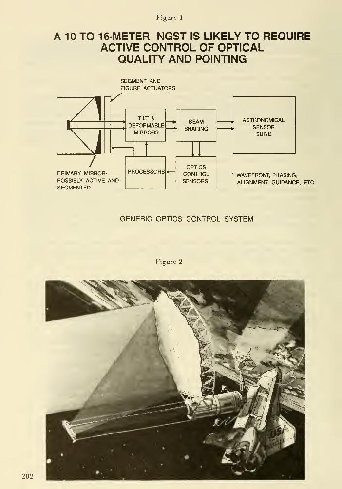
Figure 1
A 10 TO 16-METER NGST IS LIKELY TO REQUIREACTIVE CONTROL OF OPTICAL
QUALITY AND POINTING
SEGMENT ANDFIGURE ACTUATORS
Zl
/
>/
TILT &
DEFORMABLEMIRRORS
PRIMARY MIRROR-POSSIBLY ACTIVE ANDSEGMENTED
BEAMSHARING
PROCESSORSOPTICSCONTROLSENSORS*
ASTRONOMICALSENSORSUITE
* WAVEFRONT, PHASING,
ALIGNMENT, GUIDANCE, ETC
GENERIC OPTICS CONTROL SYSTEM
Figure 2
202
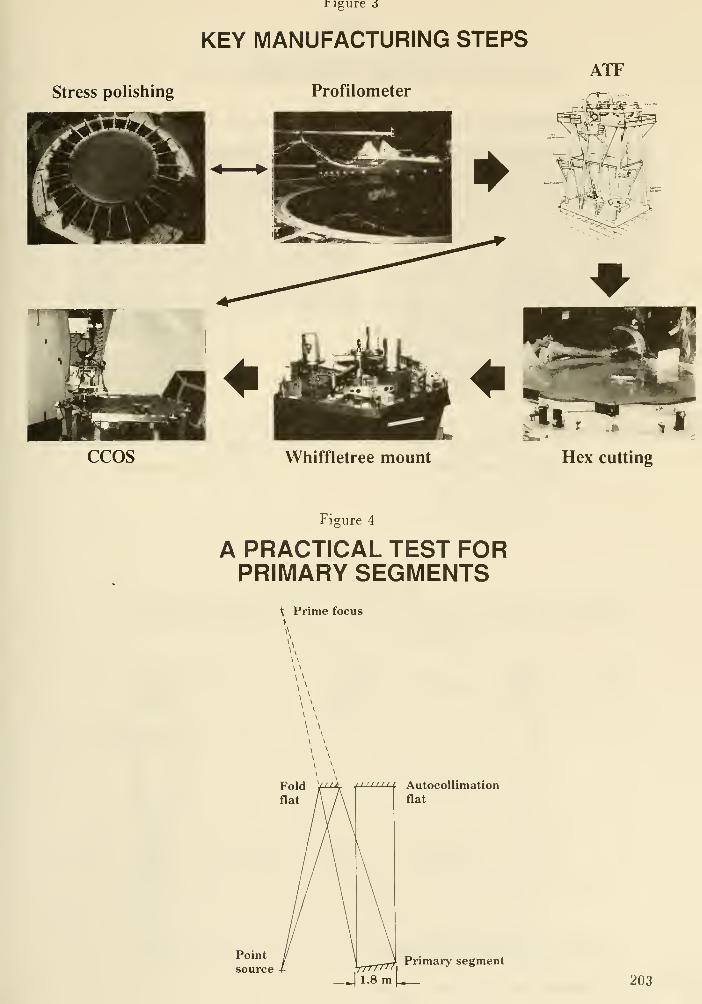
Stress polishing
rigure 6
KEY MANUFACTURING STEPS
Profilometer
ATF
CCOS Whiffletree mount Hex cutting
Figure 4
A PRACTICAL TEST FORPRIMARY SEGMENTS
\ Prime focus
Autocollimation
flat
Yrrrrn,1.8 m \^
Primary segment
203
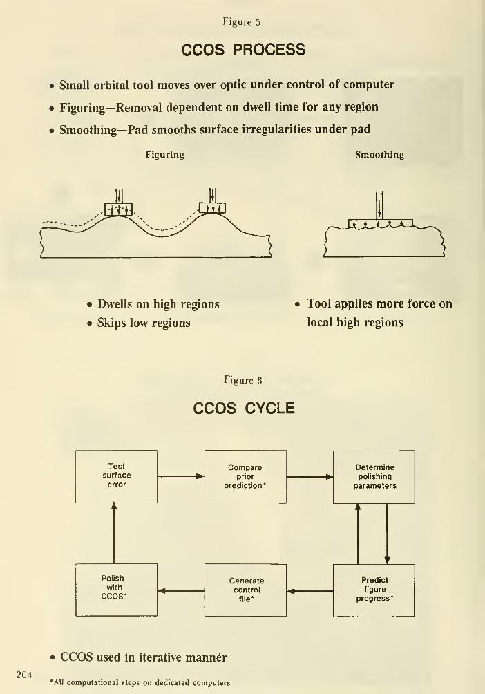
Figure 5
CCOS PROCESS
• Small orbital tool moves over optic under control of computer
• Figuring—Removal dependent on dwell time for any region
• Smoothing—Pad smooths surface irregularities under pad
Figuring Smoothing
• Dwells on high regions
• Skips low regions
Tool applies more force on
local high regions
Figure 6
CCOS CYCLE
Test
surface
error
Polish
with
CCOS*
Compareprior
prediction*
Generatecontroi
file*
Determinepolishing
parameters
Predict
figure
progress*
204
• CCOS used in iterative manner
*A1I computational steps on dedicated computers
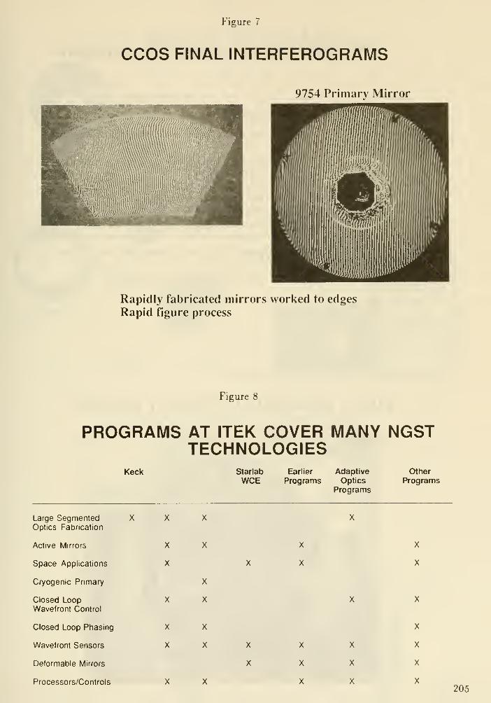
Figure 7
CCOS FINAL INTERFEROGRAMS
9754 Primary Mirror
Rapidly fabricated mirrors worked to edges
Rapid figure process
Figure 8
PROGRAMS AT ITEK COVER MANY NGSTTECHNOLOGIES
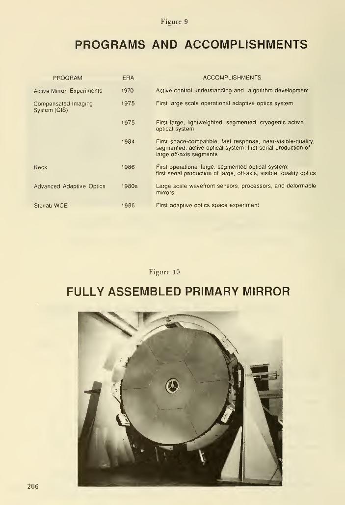
Figure 9
PROGRAMS AND ACCOMPLISHMENTS
PROGRAM
Active Mirror Experiments
Compensated ImagmgSystem (CIS)
Keck
Advanced Adaptive Optics 1980s
Starlab WCE
ERA ACCOMPLISHMENTS
1970 Active control understanding and algonthm development
1 975 First large scale operational adaptive optics system
1975 First large, lightweighted, segmented, cryogenic active
optical system
1984 First space-compatible, fast response, near-visible-quality,
segmented, active optical system; first serial production of
large off-axis segments
1986 First operational large, segmented optical system;
first senal production of large, off-axis, visible quality optics
Large scale wavefront sensors, processors, and deformable
mirrors
1986 First adaptive optics space experiment
Figure 10
FULLY ASSEMBLED PRIMARY MIRROR
206

Figure 11
ADAPTIVE OPTICS FORIMAGE COMPENSATION
I'ncompensated
i-^i^'
Deformablemirror
Imagingdetector
Wavefrontsensor
Wavefrontprocessor
Compensatedimage
Figure 12
LOW-VOLTAGE KILOACTUATORMIRROR—PRINTED WIRING CONCEPT
Pusher
207

DISCUSSION
Angel: You got close to actually showing us what kind of quality you can get with computer controlled
polishing. You showed an interferogram with rather closely-spaced fringes. You do phase-shifting
interferometry and so real numbers are probably available. Can you tell us what quality can be
obtained?
Vyce: I cannot say exactly what the quality is, but I am sure that it can be excellent for visible
wavelength optics.
Angel: I can see wiggles in the interferogram so it is probably not adequate for ground-based systems,
and almost certainly not for the space optics that we are talking about here.
Unidentified : Those are not corrected optics - that is an active mirror and is Jis manufactured without
the corrections that will be applied.
Vyce: Angel is referring to the finer-grained structure which would not be corrected out. I am not
certain that this is a finished unit, by the way.
Angel: There is a concern about computer-controlled polishing, and so I urge that when you come to
talk to astronomers you give us numbers so that we can see how well the technique is doing.
Breckinridge: Ate you doing any work on ion polishing?
Vyce: Not yet, but we may in the future.
Nelson : With regard to Angel's comments. Two of our mirrors for the Keck telescope had final
polishing with CCOS and, ignoring the edge problems with CCOS, the mirrors were polished to
surface errors below 20 nm. There were edge problems and there were high frequency errors at the
10 nm rms level that led us to go to a more cost-eiTective solution, namely warping harnesses. Since
it is an iterative process, Itek may be able be able to do better. The edge efiects were a particular
concern to us because it ia a segmented mirror.
Vyce: I think that we have a way of dealing with the edge efiects and so we are checking that out
Kahan : Dick, would you agree that its fair to say that meter class optics can be made to visible
quality levels in about 30 weeks, given today's CCOS techniques? This makes the primary mirror less
of a cost driver, given the epic aerospace aspects of the total program.
Vyce: Yes. In fact, 30 weeks is pretty conservative.
208

Fabrication of large and fast mirrors
with extraordinarily smooth surfaces
Ernst-Dieter Knohl
Carl Zeiss
Abstract
At the inception of the Next Generation Space Telescope (NGST) program we should ask what
technologies are needed and are these technologies already available. It is clear that an important area is
the fabrication of highly polished optical surfaces, in order to get high resolution images. For the NTTprogram Zeiss developed a fast polishing technique to generate super smooth surfaces, and patented it
as membrane tool technology. The striking results of the ESO NTT demonstrate how powerful these
new tools are: the concentration of energy of the 3.6 m primary turned out to be twice as good as the
HST, and 50 times less expensive (Neglecting the atmospheric contribution to the image spread) Rapid
metrology is essential for fast figuring process. Zeiss is running interferometry in "Real Time" averaging
hundreds of frames in one evaluation. Therefore no vacuum chamber is needed. An adequate mirror
support system for figuring and testing has been built for the NTT primary and has been qualified in
interferometric tests. For an active supported mirror Zeiss prefers the thin, solid meniscus solution for
best optical performance. With such designs, mirror diameters are limited to between 8 and 9 m.
1. The conventional figuring technique
In the fabrication of a large aspherical mirror, the conventional technique is to begin
with a spherical lapping step with area covering tools. Figuring of a spherical surface needs
no special machine control just a turning workpiece and an oscillating tool. The next step
is to pohsh the spherical surface. The third step is a interferometric test. Next aspherical
deformation of the surface is done by lapping, and the asphere is poUshed. Finally, an
interferometric test with a compensating system will give the input to the next pohshing
cycle. This process being repeated until the figure and poUsh are satisfactory.
This time consuming process was estabhshed to generate the optic of the 3.6 m tele-
scope MPIA with 35 n deviation from the best fitting sphere and a F-number F/3.5. In
four years a RMS wavefront aberration of 24 nm was reached. The first light of the MPIAtelescope was in 1984 and Birkle has published "Operation and Test Results" in Ref.l.
With the same technology a second 3.6 m optic was fabricated for the Iraqi Observa-
tory on Mt. Korek. Unfortunately the complete telescope is stored today in Baghdad.
2. A new polishing technique to generate super smooth surfaces
The ESO NTT optics was specified to have 80% energy within 0.15 arc sec diameter.
This challenging requirement can only be met with new fabrication technologies. TheNTT primary has a free aperture of 3.5 m, a F-number F/2.2 and about 200 /i deviation
from the best fitting sphere. To reach this goal Zeiss developed new tools for super
smooth surfaces, a fast metrology with high resolution and an adequate support system.
The results are striking and are pubhshed by ESO in Ref. 2 and 3, and show about a
factor of three better energy concentration than standard techniques.
209
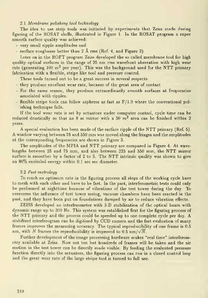
2.1 Membrane polishing tool technology
The idea to use strip tools was initiated by experiments that Zeiss made dnring
figuring of the ROSAT shells, illustrated in Figure 1. In the ROSAT program a super
smooth surface quality was achieved:
- very small ripple amplitudes and
- surface roughness better than 2 A rms (Ref. 4, and Figure 2)
Later on in the ROFT program Zeiss developed the so called membrane tool for high
quahty optical surfaces in the range of 25 nm rms wavefront aberration with high wear
rate (generating 100 m^ per year). This was the background used for the NTT primary
fabrication with a flexible, stripe like tool and pressure control.
These tools turned out to be a great success in several respects
- they produce excellent wear rate, because of the great area of contact
- For the same reason, they produce extraordinarily smooth surfaces at frequencies
associated with ripples.
- flexible stripe tools can foUow aspheres as fast as F/1.0 where the conventional pol-
ishing technique fails.
If the tool wear rate is set by actuators under computer control, cycle time can be
reduced drastically so that an 8 m mirror with a 50 m^ area can be finished within 2
years.
A special evaluation has been made of the surface ripple of the NTT primary (Ref. 5).
A window varying between 25 and 550 mm was moved along the fringes and the ampUtudesat the corresponding frequencies are shown in Figure 3.
The ampUtudes of the MPIA and NTT primary are compared in Figure 4. At wave-
lengths between 25 and 75 mm, and also between 225 and 550 mm, the NTT mirror
surface is smoother by a factor of 2 to 3. The NTT intrinsic quality was shown to give
an 80% encircled energy within 0.1 arc sec diameter.
2.2 Fast metrology
To reach an optimum rate in the figuring process all steps of the working cycle have
to mesh with each other and have to be fast. In the past, interferometric tests could only
be performed at nighttime because of vibrations of the test tower during the day. Toovercome the influence of test tower seeing, vacuum chambers have been erected in the
past, and they have been put on foundations damped by air to reduce vibration effects.
ZEISS developed an interferometer with 3-D stabilization of the optical beam with
dynamic range up to 300 Hz. This system was estabhshed first for the figuring process of
the NTT primary and the process could be speeded up to one complete cycle per day. AstabiHzed interferogram can be digitized by CCD camera and the fast evaluation of manyframes improves the measuring accuracy. The typical reproducibiHty of one frame is 0.5
nm, with TV frames the reproducibiHty is improved to 0.5 nm/VW.Further development of the image processing hardware makes "real time" interferom-
etry available at Zeiss. Now not ten but hundreds of frames will be taken and the air
motion in the test tower can be directly made visible. By feeding the evaluated pressure
function directly into the actuators, the figuring process can run in a closed control loop
and the great wear rate of the large stripe tool is turned to full use.
210

2.3 Supporting System
The advanced technology of active optics leads to more and more thin, solid mirrors
with the most possible homogeneity. The aspect ratio of the NTT primary was chosen
D/h = 15. New projects Hke SOFIA or VLT tend to D/h = 45. Therefore the new mirror
quaHty depends strongly upon the optimized supporting system. The mirror support
during figuring has to guarantee the following functions:
- Supporting the mirror axial weight
- Carrying the axial and tangential force variations of the polishing loads
- Damping of the pohshing loads
- Supporting for interferometry without imposing any constraints
- Active correction of long wavelength deformations to increase the dynamic range of
the test system
During the NTT program Zeiss measured the quahty of the support system by turning
the mirror with respect to the supporting pads. Finally a perfect match was found between
data from mirror support during fabrication and data from mirror support in the telescope
cell . The beautifully sharp astronomical images are a direct consequence of the support
quality.
Active correction makes sense only if the mirror body is solid and homogeneous. In
case of a structured mirror the active bending corrects for long wave errors but introduces
ripples with even steeper slope errors. This effect have been demonstrated with simple
paper models.
3. Limits of mirror dimensions
In a study phase of the VLT program Zeiss developed all the technologies needed for
8 m mirror figuring (Ref. 6). The biggest useable monolithic glass mirror is between 8
and 9 m diameter for several reasons:
- fabrication of blank "
- mirror handling
- transportation on road and by ship
Many ideas exist for the construction of larger primaries. For example the MMTsolution or the Keck solution with all its attendant problems. To overcome the problems
with figuring of off-axis aspherical elements, Zeiss is studying a 12 m primary made out of
4 segments. The idea is to assemble these segments at simulated zero-g into a monolithic
blank, do the polishing and interferometric testing in the well known on-axis manner, to
take the four segments apart for transportation and to align and assemble them again on
site in the telescope cell.
Thorough calculations have still to validate this approach. But the great advantage
of large coherent optics is obvious, and the approach is worth pursuing.
211
4. Conclusions
- The largest monolithic mirrors that can be produced, handled and transported are
limited to diameters between 8 and 9 m.
- Two years is typically needed for figuring, preparation of supporting pads and testing
to finish 50 m^ of super smooth optical surface corresponding to an encircled energy
of 80% within 0.2 arcsec diameter.
- The great improvement of the NTT optics was achieved with stripe tools and actuators
under pressure control, with fast IR and visible interferometry, and with unconstrained
mirror support.
- The full advantages of active optics are only obtained if ripples at spatial frequencies
above the controlled frequencies are accordingly reduced.
- Active correction of honeycomb mirrors makes no sense, while long wave deformations
are corrected by active bending, short ripples caused by the structure occur with even
greater slope errors.
- At Carl Zeiss rapid active tools to generate fast optics were developed and used in
the NTT program. Real time metrology is available with correction of test tower
seeing and vibration and adequate supporting systems have been used for mirrors
with reduced stiffness.
Figures 5 illustrates the evolution of surface polish quality with time for the NTT.Figure 6 shows the time actually taken to figure mirrors of given aspheric deformation in
three cases, and predictions for the VLT.
References
1 K. Birkle and U. Hopp, Das 3.5 m teleskop MPIA Operation and test Results, Mit-
teilungen der AG Nr. 68, 1987
2 R. N. Wilson et al., ESO Active Optics: the NTT and the Future, ESO Messenger
No. 53, Sept. 1988
3 R. Wilson ESO, "First Light" in the NTT, ESO Messenger No. 56, June 1989
4 K. Beckstette, Aspects of Manufacturing Grazing Incidence X-Ray Mirrors, Carl Zeiss,
D-7082 Oberkochen, West Germany SPIE Vol . 645 (1986)
5 H. Geib, C. Kiihne, E. Morgenbrod, How to Quantify Ripple, Proc. lAU Colloquium
No. 79, April 1984
6 E.D. Knohl et al, 8 m Class Primary: Figuring, testing, handhng, SPIE Vol . 1013
(1988)
212
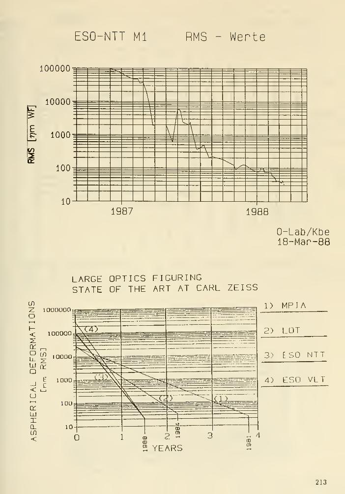
ESO-NTT Ml RMS - Werte
100000
10000
?r 1000
100
10
E
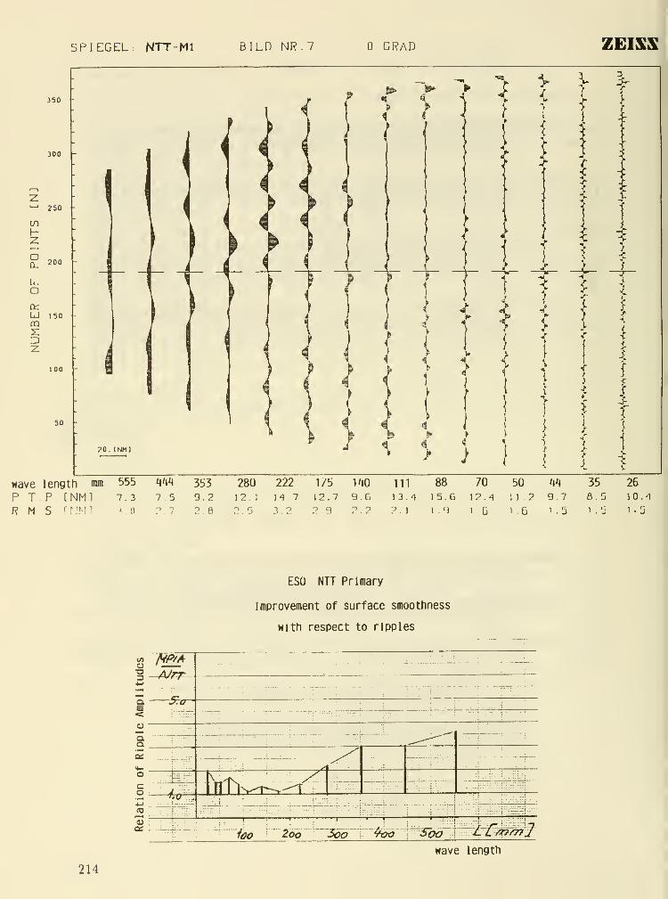
SPIEGEL: NTT-MI BILD NR.7 GRAD ZEISS
300
^ 250 -
inHZ
£ 200
o
UJ 150OQ
i
20. INM)
^
4\ I
1
/
I
ii\
J-
I
4^
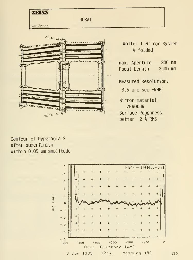
Wolter I Mirror System
^ folded
max. Aperture
Focal Length
800 mm
2^00 mm
Measured Resolution:
3.5 arc sec FWHM
Mirror material:
ZERODUR
Surface Roughness
better 2 A RMS
Contour of Hyperbola 2
after superfinish
within 0.05 pm amplitude
-.5
-GOO
.5
DISCUSSION
Miller : Can the membrane polishing be extended beyond 8 meters?
Knohl : Yes, we think that it could be extended beyond that point.
niingwortli: Mike Krim noted a "print-through" problem with thin mirrors. For thin mirrors do
you think that the technique will work without "print-through" of the support so that the resulting
segments are smooth on small scales?
Knohl : The technique works on rotationally-symmetric mirrors. We are now working on the 12 meter
DGT telescope and are discussing putting the segments together and polishing them as a monolith.
Krim: The "quilting" problem arises particularly in lightweight mirrors that are "pocketed" from
the back. There are tradeoffs that can be made in the degree of lightweighting, the cell spacing, the
faceplate thickness, and the tool pressure. It is a midtiparameter (7?) tradeoff.
Knohl: Yes, you have to do an optimisation of the process.
Angel: On that topic, if you make a lightweight glass honeycomb structure for a large space telescope
you are talking about really very thin faceplates - maybe a cm or less. Under any realistic polishing
pressure, maybe a tenth of a psi, for example, the cells would have to be very small to avoid deflections.
They would probably have to be an inch or two in size. The only advantage of a computer-controlled
polisher in not "quilting" the surface is when the tool size is less than a cell size, say a cm or two. I
find it difficult to see that this small tool advantage could be usefully realized for polishing a 16 meter
mirror. Therefore I do not see that there is a domain where small tool polishers will be used for large,
lightweight space optics.
niingworth: Have you thought about using your membrane lap technology on segments' surfaces by
polishing all the segments at once in a support somewhat like that described by Mike Krim of Perkin
Elmer?
Knohl : Yes, the membrane tool can be used for segments of any shape. In this case, the workpiece
doesn't move and the membrane tool is oscillating in the surface plane. The point still being under
discussion is the best set up for the metrology of off-axis segments.
216

Economical Production of Large Optics *
David Pileri and William Prensky
Eastman Kodak Company, Federal Systems, Advanced Technology Products
Special Optics Fabrication, Rochester, New York 14650
ABSTRACT
Optics for large systems are frequently ultra-lightweight and deformable by design. They often have
unusual shapes and include non-rotationally symmetric surface figures. Surface roughness, subsurface damage,
light scattering and laser damage threshold specifications are also frequently required. Manufacturing techniques
being developed to address these stringent requirements will be discussed.
1. INTRODUCTION
As large, monolithic optical structures are no longer feasible, large optical systems typically incorporate
multi-segmented arrays.''^ Spacebome systems can be assembled in orbit from segments that can be
transported in smaller launch vehicles. Space-based and ground-based systems use active optics to compensate
for distortions. Manufacturing these optical elements presents many challenges. Conventional processes,
materials and methods are not capable of figuring these active optics in a cost effective manner. New,
deterministic manufacturing techniques need to be developed. These techniques must not only be capable of
accurately figuring large, complex, optical components; they must also support a performance level requiring
minimum light scattering and minimum laser threshold damage (resulting from subsurface damage and surface
microroughness) . On-going process developments at Eastman Kodak Company have resulted in optical
manufacturing technology that will provide the deterministic, cost effective fabrication of large state-of-the-art
optical components.
2. LARGE ASPHERIC OPTICS TECHNOLOGY
Large primary mirror designs as shown in Fig. 1 are segmented representing a parent optic several meters
in diameter. In order to reduce the areal density the mirror segments are either lightweighted, or consist of thin,
solid facesheets (Fig. 2) . Regardless of the configuration, the segments are deformable by design (under active
actuator control in the system). Glass-ceramic or stable glass materials such as fused silica, ULE®, or Zerodur®are likely candidates for substrates.
2.1 Aspheric Curve Generation
The generation of an aspheric profile (i.e., diamond grinding of the three-dimensional aspheric equation
to within a few waves of nominal ) for axisymmetric optics is typically accomplished by spinning the optic about
the optical/mechanical axis and moving a grinding head radially. This is not possible for large, off-axis
elements. Therefore, reliable aspheric curve generation of unusually shaped, off-axis segments requires a
generating machine with state-of-the-art size, stiffness, accuracy, and meuology. A machine of this caliber
would also allow manufacturing large anamorphic designs and using ductile grinding techniques^ to produce a
specular surface.
Process developments at Kodak have resulted in machinery capable of generating axisymmetric aspheric
elements up to 0.8m diameter, and to within 6 iim p-v of nominal. Kodak has now expanded this process
capability to large off-axis segments by commissioning Cranfield Precision Engineering, Ltd., to build a
three-axis CNC generating machine with a working envelope of 2.5m x 2.5m x 0.6m.* The OAGM 2500(Off-Axis Generating Machine) pictured in Fig. 3 features a) a precision air bearing grinding spindle, b) an
in-situ metrology system using a retractable air bearing measurement probe, c) a metrology frame based on
distance measuring interferometers that reference to three precision mirrors, and d) a Granitan® machine
structure for stability yielding a total machine weight of 130 tons. The machine is expected to be on line in
December 1989.
This paper was presented by John Keller, Kodak 217

Secondary Mirror
Alignment and Focus,
Actuators
Graphite/Epoxy
Support Tubes
Secondary
Mirror
Primary Mirror-
Segments
Segment Phasing andDeformation Actuators
Graphite/Epoxy
Structure
SegmentPhasing and
Alignment
Sensors
Fig. 1. Example of segmented primary mirror design.
Fig. 2. Example of facesheet mirror blank.
218
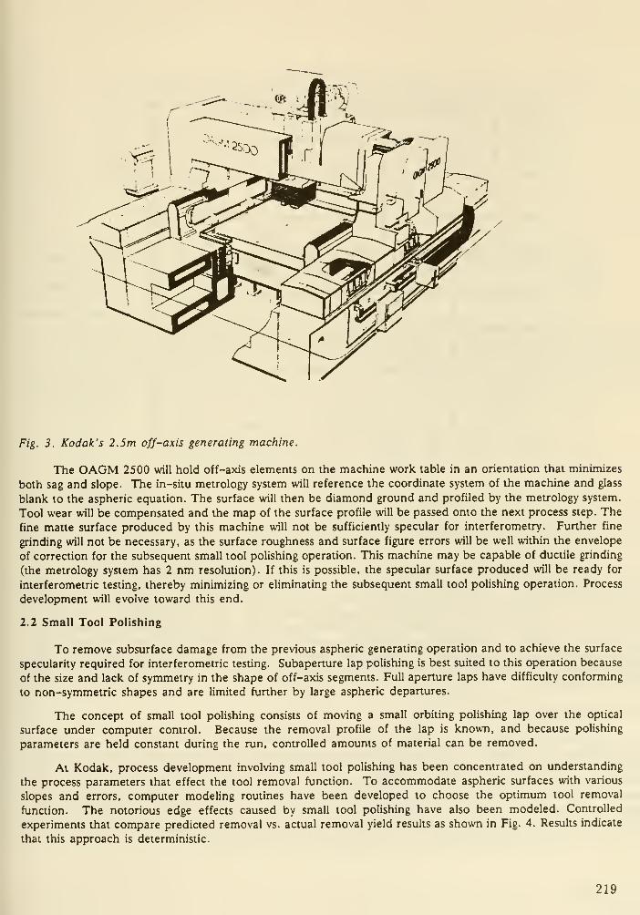
Fig. 3. Kodak's 2.5m off-axis generating machine.
The OAGM 2500 will hold off-axis elements on the machine work table in an orientation that minimizes
both sag and slope. The in-situ metrology system will reference the coordinate system of the machine and glass
blank to the aspheric equation. The surface will then be diamond ground and profiled by the metrology system.
Tool wear will be compensated and the map of the surface profile will be passed onto the next process step. The
fine mane surface produced by this machine will not be sufficiently specular for interferometry. Further fine
grinding will not be necessary, as the surface roughness and surface figure errors will be well within the envelope
of correction for the subsequent small tool polishing operation. This machine may be capable of ductile grinding
(the metrology system has 2 nm resolution). If this is possible, the specular surface produced will be ready for
interferometric testing, thereby minimizing or eliminating the subsequent small tool polishing operation. Process
development will evolve toward this end.
2.2 Small Tool Polishing
To remove subsurface damage from the previous aspheric generating operation and to achieve the surface
specularity required for interferometric testing. Subaperture lap polishing is best suited to this operation because
of the size and lack of symmetry in the shape of off-axis segments. Full aperture laps have difficulty conforming
to non-symmetric shapes and are limited further by large aspheric departures.
The concept of small tool polishing consists of moving a small orbiting polishing lap over the optical
surface under computer control. Because the removal profile of the lap is known, and because polishing
parameters are held constant during the run, controlled amounts of material can be removed.
At Kodak, process development involving small tool polishing has been concentrated on understanding
the process parameters that effect the tool removal function. To accommodate aspheric surfaces with various
slopes and errors, computer modeling routines have been developed to choose the optimum tool removal
function. The notorious edge effects caused by small tool polishing have also been modeled. Controlled
experiments that compare predicted removal vs. actual removal yield results as shown in Fig. 4. Results indicate
that this approach is deterministic.
219

i
^2
1.0
o.e
0.6
0.4
0.2
0.0
•0.2
0.4
•0.6-

Table 1
SMALL TOOL POLISHING AND ION FIGURING ANALOGY
Removal Function Parameters X Path Profile = Figuring
Small Tool
Polishing
Dwell Time
Obliquity
Pad & Orbit Diameter
Pad & Orbit Speed
Rectangular
X.Y.Z
Ion
Figuring
Dwell Time
Obbquity
Beam Energy
Gas Type
Temperature
Rectangular
X.Y.Z
Kodak has supported process development in ion figuring and has significant experience with the
substrates fused silica and silicon carbide using ion plasma etch^ on optics up to 100 mm in diameter. We have
now increased this process capability by commissioning DynaVac Company, Division of Tenney Engineering, to
build a vacuum chamber capable of ion figuring (Fig. 5). This chamber has a 2.5m capacity. The ion source
position is controlled by a five-axis CNC positioner (x.y.z, ^x, 4)y). The machine is expected to be on line in
September 1989.
TRANSLATIONSTAGE
Fig. 5. Kodak's ion figuring system.
221

With the IFS (Ion Figuring System), off-axis optical elements will be figured to their final specification.
Interferometric data will be passed in closed loop fashion to the machine's controller for each iteration. Fewiterations are expected, as this process is highly deterministic. The logical extension to this process development
is a state-of-the-art machine that exhibits in-situ metrology and thin film coating capability. Process
development will evolve toward this goal.
3. LARGE PLANO OPTICS TECHNOLOGY
Multi-segmented piano optics are also a design possibility. Again, these optics may be active by design,
being either ultra-lightweighted (Fig. 6) or facesheets. Glass-ceramic or stable glass materials such as fused
silica, ULE®, or Zerodur® are likely candidates for substrates. We believe that surface figuring before ion
figuring is best accomplished using planetary polishing techniques.
Fig. 6. Example of Im piano ultra-lightweight mirror.
3.1. Planetary polishing
Planetary polishing machines have a horizontal, annular-shaped lap, the flatness of which is maintained
by a conditioner polishing on the surface along with two or more workstations. Within each workstation, optics
are held in septums which are motor-driven to maintain rotational synchronization with the lapping table.
Recirculating slurry systems are frequently used and environmental controls are necessary to maintain figure
control of the lap. Planetary polishing is an efficient method of polishing large piano optics. Numerous optics
can be processed simultaneously and stock removal can be carefully controlled, minimizing subsurface damage.Fig. 7 shows a 4m planetary polishing machine designed and built at Kodak to support Im optics for the
Lawrence Livermore National Laboratory's Nova Laser program. The table for this polisher is a single piece of
granite weighing 33 tons. The conditioner is a 2.5 ton piece of fused quartz.
Final figuring for large piano optics no longer needs to be completed on the planetary polishing machine.
Once subsurface damage is removed and the surface error is within a fraction of a wave of specification, ion
figuring will be used to complete the manufacturing process. For large piano optics used in transmission ion
figuring is an extremely attractive method to correct for inhomogeneities in the glass.
222

Fig. 7. Kodak's 4m planetary polishing machine.
4. CONCLUSIONS
Kodak's new optical fabrication and finishing systems are undergoing final acceptance tests and should be
operational by the end of 1989. They will be usable with beryllium and other materials, as well as glasses. Their
application will substantially reduce the time and cost traditionally associated with large optics. Kodak's
developments have been driven by our growing concern that, despite growing needs for large optical systems,
their deployment could be inhibited by expensive optical components.
5. REFERENCES
^ P.N. Swanson, J.B. Brekinridge, A. Diner, R.E. Freeland, W.R. Trace, P.M.McElroy, A.B. Meinel and A.F.
Tolivar, "System Concept for a Moderate Cost Large Deployable Reflector (LDR)," Optical Engineering, Vol.
25, No. 9, pp. 1045-1054, September 1986.
2 D.C. Kline, "Space-based Chemical Lasers for Ballistic Missile Defense (BMD)." Proceedings of the Inter-
national Conference on Lasers '87, F.J Duarte editor, pp. 205-217, STS Press, McLean, VA, 1988
3 N.J. Brown and B.A. Fuchs, "Brittle to Shear Grinding Mode Transition for Loose Abrasive Grinding," OSATechnical Digest: Optical Fabrication and Testing, pp. 23-26, November 1988.
" P.B. Leadbeater, M. Clarke, W.J. Wills-Moren, T.J. Wilson, "A Unique Machine for Grinding Large,
Off-axis Optical Components: The OAGM 2500," Precision Engineering, to be published.
5 S.R. Wilson, D.W. Reicher and J.R. McNeil, "Surface Figuring Using Neutral Ion Beams," Advances in Fab-
rication and Metrology for Optics and Large Optics, J.B. Arnold and R.E. Parks editors, Vol. 966, pp. 74-81,
SPIE, Washington 1989.
® L.N. Allen, "Precision Figuring of Optics by Ion Machining Processes," Conference on Lasers and Electro-
Optics, Baltimore, MD, Vol. 11, April 1989.
223

DISCUSSION
Nelgon : I have a question legaiding the convergence rate of ion polishing. I had heard that you could
get accuracies of 90%. What is your experience with this machine and your expectations?
Keller : While we haven't had any direct experience with large optics in the new ion facility, we have
made some estimates based on our experience with small optics. Based on our work on the HST mirror
we believe that we could cut the 18 iterations needed for that mirror with conventional techniques down
to 3 iterations. Furthermore, even though those 18 iterations involved only 70 hours of polishing, it
actually took a year to finish the mirror because of the overhead of testing, handling and setup. With
a deterministic process such as ion polishing we believe that we could do a HST mirror in about a
month.
MUler : Can you tell us what ductile grinding is?
Keller : Effectively it is like diamond turning where the materijil is sheared away instead of being
"chipped" off.
Angel: Can you give us some feel for the size of the ripples that might be left on an aspheric surface
from the polishing tool and the size of the ion beam needed to remove them?
Keller : We need some experience before we can give you some real numbers, but we do have some
cedculations.
Nelson : What is the maximum beam size that you could use?
Keller : The beam size could be 5, or 10 or 15cm. It can be made quite large.
Dlingworth: Removal of the edge ripple from your example would suggest that you need ion beams
that are a fraction (1/3-1/4) of the small tool size. Is that the size you use - several cm? If I understand
correctly, this means that the "polished" surface from the "small tool" polishing would have to have
the final desired smoothness on scales less than several centimeters.
Keller : Yes, 1/3 to 1/4 will work, but the "up modes" of the ripple are Gaussian so the same size will
work (faster removal). However, note that in one example, the low ripple mode was below the nominal
surface. In practice one must keep the ripple zone "turned up."
224
Super Smooth Optics for Extra-Solar Planet Detection
Richard J. Terrile
Jet Propulsion Lab, Caltech, Mail Stop 183-501, Pasadena, CA 91109
and
Christ Ftaclas
Hughes Danbury Optical Systems Inc., 100 Wooster Heights Rd.
,
Danbury, CT 06810
ABSTRACT
The goal of imaging planets around the nearby stars has importantscientific significance but requires the use of advanced methods of controllingdiffracted and scattered light. Over the last three years we have undertaken a
study of coronagraphic methods of controlling diffracted light and of figuringhyper-contrast optics. Progress in these two general areas have led to a
proposed space-based, 1.9 meter diameter coronagraphic telescope designedspecifically for very high performance in the imaging of faint objects near
bright sources. This instrument, called the Circumstellar Imaging Telescope
(CIT) , relies on a new high efficiency coronagraph design and the careful
control of scattered light by extremely smooth optics. The high efficiencycoronagraph uses focal plane apodization in order to concentrate diffractedlight more efficiently in the pupil. This allows convenient removal of the
diffracted light by masking off parts of the telescope pupil while notsacrificing the center of the field. Reductions of diffracted light by factorsexceeding 1000 are not only possible but are required in order to detect extra-
solar planets. Laboratory experiments with this new design have confirmed the
theoretica,l diffraction reductions to the limits of the optics used (factors of
about 300) . The extremely high efficiency of this coronagraph puts strongconstraints on the narrow angle scattered light due to figure errors in the
telescope mirror. Since planets orbiting nearby stars are expected at angulardistances of about 1 arcsecond, it is in this small angular range in whichscattering must be controlled. The figure errors responsible for scattering in
this range come from mid- spatial frequencies corresponding to correlationlengths of about 10 cm on the primary mirror. A primary mirror about 15 times
smoother than the Hubble Space Telescope mirror is required for the CIT.
Laboratory experiments indicate that small test mirrors can be fabricated with
existing technology which come within a factor of two of this requirement.
1 . INTRODUCTION
In this paper we will discuss the application of super- smooth optics to the
problem of the direct detection of extra-solar planetary systems. The two key
technology developments which have enabled serious consideration of this
scientific problem are in the control of diffracted light and in the fabrication
of super-smooth optics. This paper will concentrate on the control of
225

diffraction. Further discussion of mirror scattering and fabrication issues can
be found in reference 1
.
Over the last three years a joint program between the Jet Propulsion
Laboratory (JPL) and the Perkin- Elmer Corporation (now Hughes Danbury Optical
Systems Inc.) has been organized to define the requirements for optics capable
of directly detecting extra-solar planetary systems from Earth orbit. The mainconclusions from this study were that: 1) Direct detection of nearby extra-
solar planets is possible from a meter-class orbital telescope designed to
reduce diffracted and scattered light to levels about 1000 times belowdiffraction from the unapodized aperture. Furthermore, there are a wide range
of scientific goals in planetary science and in astrophysics that areaddressable with such an orbital telescope. 2) A high efficiency coronagraph
was designed and tested in the laboratory which can reduce diffracted light to
these required levels without sacrificing the center of the field of view and
without dramatically reducing the effective aperture diameter of the telescope.
3) The requirements on the mirror figure demand a mirror about 15 times
smoother than the HST primary at mid-spatial scale frequencies (10 cm).However, laboratory and fabrication experiments have shown that currentmetrology is capable of making such measurements and that small (30 cm diameter)
test mirrors have been fabricated with nearly flight quality figures. As a
result of these conclusions we have proposed a flight project called the
Circumstellar Imaging Telescope (CIT) '.
2. THE CIRCUMSTELLAR IMAGING TELESCOPE (CIT)
The CIT consists of a 1.9 meter diameter telescope in which small angle
scatter has been greatly suppressed, mated to a camera that can implement a
variety of diffraction control strategies. These strategies, including a newhigh efficiency design, are chosen to realize the performance inherent in the
fore-optics and to maximize the scientific return of the mission. Thus bothdiffraction and scatter are comparably reduced unveiling the circumstellarenvironment. One arcsecond away from a bright point source the baseline CITwill have a background level more than 5 magnitudes per square arcsecond fainter
than the Hubble Space Telescope (HST) leading to a much higher sensitivity near
bright objects.
The key design features of the CIT are control of scattered light through
use of super-polished mirrors, control of diffracted light through use of a
coronagraph, and control of image motion through use of an internal fine
pointing system. Computer modeling indicates that, with only moderate advances
in mirror fabrication technology, the CIT will be able to detect Jupiter sized
planets around solar type stars at distances out to ten parsecs
.
3. PLANETARY DETECTION AND CHARACTERIZATION
At the very heart of Planetary Science lies the question of the uniqueness
of life on Earth. Current theories entertain the idea that suitable conditions
for life probably occur commonly throughout the galaxy on planets surrounding
stars. Therefore, a corollary to this fundamental question is what is the
nature and probability of planet formation. With our solar system as the only
available model, clues to the nature of planet formation are derived from
observations of current conditions. The planets orbiting the sun are co -planar,
226

co-rotating and generally show a compositional ordering with distance from the
sun. This regularity is thought to be a relic of the conditions during the
formation of the sun and solar system. Models of the formation of the planets
have them forming in a collapsing nebula or disk of material around the early
sun. Indeed, recent observations of circumstellar disks indicate that these
conditions do occur early in the lifetimes of stars. In order to gain a deep
understanding of the entire process of planetary formation it is desirable to
observe the various stages of evolution from the earliest stages of stellar
formation to a survey of mature planetary systems. Recent progress has be made
in detection and imaging of circumstellar disks, but direct planet detection
remains the most challenging observational goal.
The most difficult aspect of direct detection of mature planetary systems
is the large difference in brightness between the planets and parent star. In
the example of Jupiter around the sun the brightness ratio in visible light is a
factor of about 1 billion . Furthermore, the maximum diameter a planet can have
is about 10% greater than Jupiter before additional mass causes the core to
become degenerate and the radius to decrease with added mass. The visual
magnitude of Jupiter, viewed from 10 parsecs, is 25.9 at opposition, 27.4 at
quadrature and 27.5 on average. Only the presence of a broad ring system could
add to the equivalent cross section and therefore the brightness of a large
planet. The challenge of direct detection of planets is not in the detection of
a faint signal, but in separating this relatively faint planetary component from
the dominant background glare of the parent star. Even for relatively nearby
stars the angular separations of parent star and planet are an arcsecond or
less. It is now recognized that the HST will not be able to directly detect
extra- solar planetary systems because of the inherent levels of scattered light
in the telescope ' '.
4. CONTROL OF DIFFRACTED LIGHT
The CIT baseline design includes diffraction control technologies which
fully exploit the low scatter telescope optics. The CIT camera will use
coronagraphic approaches to suppress diffraction near single bright in- field
sources, as with the extra-solar planetary detection problem, and a pupil
apodization approach to suppress the diffraction wings of all sources in crowded
fields, as in observations of stellar populations in compact clusters.
Traditional approaches to diffraction reduction have involved eitherapodization (rolling-off or softening the edge of the entrance pupil to lower
diffraction sidelobes) , or coronagraphic re-imaging systems. The requirement for
large diffraction reductions at sub -arcsecond scales imposed by the planetary
detection problem argues against pupil apodization which extracts increasing
penalties in effective collecting area for improved small angle performance .
o
The coronagraph was first employed by Lyot in 1934 to observe the solar
corona. At the first focus the source is occulted and then the entrance pupil
is re -imaged. The occultation results in the remaining diffracted light in the
system concentrating in a ring approximately centered on the image of the edge
of the entrance pupil. The pupil or Lyot stop masks off part of this ring so
that when the light is re -imaged to a second focus the diffraction pattern is
reduced in intensity. The same principle can be applied to secondaryobscuration and secondary support structure so our subsequent discussion will
227

concern itself with a simple circular unobscured pupil.
As a typical example of the classical coronagraph, when the occulting mask
covers about 5 diffraction radii (i.e. 5 lambda/d) and the Lyot stop is 90% of
the pupil image in diameter, the reduction in diffraction is about a factor of
100. Calculation of the pupil plane and first and second focal plane
intensities for this case are shown in Figures la and b. Closing down the Lyot
stop in this case produces no further gains since the remaining light in the
pupil plane is virtually uniformly distributed. The only way to improve the
diffraction reduction efficiency of the coronagraph is to enlarge the occulting
stop giving up valuable science field. For a 1.9 meter aperture the 5 lambda/d
disk is already occulting the central arc second of the field which we
considered marginally acceptable. Furthermore the hard edge of the occulting
mask has rung through the system creating a diffraction peak centered on the
stop edge further reducing the useful field. In short the classical coronagraph
is inefficient, and performs worst where it's most needed, near the center of
the field.
aUJ>
2 .* .s a
RADIUS (ENTRANCc PUPIL - 1)
2 4 6 8 10 12 1* 16
RADIUS (SCALED TO DIFFRACTION RADIUS)
Figure la Figure lb
Figures 1 a and b show the distribution of light in the pupil of a Lyot type coronagraph and in the first
and second focal planes, respectively. Note that in Rgure la diffracted light is concentrated in a ring
near the outer edge of the entrance pupil but is only reduced by about a factor of 1 Gin the center of
the pupil. A 90% Lyot mask effectively removes the outer bright ring. Rgure lb shows the original
star signal in the first focus (top cun/e) and in the second focus (bottom). Note that at the second
focus light is reduced by about a factor of 100 but the edge of the occulting mask produces a bright
ring of light at about 5 Airy rings.
The key to improving the performance of the coronagraph is to pack more
diffracted light in the pupil plane ring. This suggests apodization in the
conjugate or focal plane. In Figures 2a and b we show the same intensity plots
as in Figures la and b but now the hard occulting mask has been replaced by a
graded transmission mask whose amplitude transmission varies as [l-exp(r/rQ)**2]
with r adjusted to give 50% intensity transmission at the 5 lambda/d point.
The focal plane apodization has concentrated the diffraction pattern in the
pupil plane into a single broad peak. The diffraction intensity reduction is
comparable to the previous case for a 90% Lyot stop but now when the Lyot stop
228
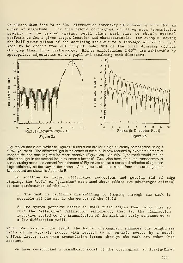
is closed down from 90 to 80% diffraction intensity is reduced by more than anorder of magnitude. For this hybrid coronagraph occulting mask transmissionprofile can be traded against pupil plane mask size to obtain optimalperformance for a given target location and characteristic. For example, movingthe half power points of the occulting mask out to 8 larabda/d allows the Lyotstop to be opened from 80% to just under 90% of the pupil diameter withoutchanging final focus performance. Higher efficiencies (>10 ) are achievable byappropriate adjustments of the pupil and occulting mask diameters.
' -1
zUJaMl>
cc
8
2 .* .5 .8 1.0
Radius (Entrance Pupii = 1)
Figure 2a
1.2
U5Z
UJ>
!UJa.
8
2 * 6 8 10 12 14
Radius (In Diffraction Radii)
Figure 2b
Hgures 2a and b are similar to Hgures la and b but are tor a high efficiency coronagraph using a-
90% Lyot mask. TTie diffracted light in the center of the pupii is now reduced by over three orders of
magnitude and masking can be more effective (Figure 2a). An 80% Lyot mask would reduce
diffracted light in the second focus by atX3ut a factor of 1700. Also because of the transparency of
the occulting mask, the second focus (bottom of Rgure 2b) shows a smooth distribution of light andhigh efficiency all the way to the center. Photographs of these cases from our coronagraphic
breadboard are shown in Appendix B.
In addition to larger diffraction reductions and getting rid of edgeringing, the "soft" or "gaussian" mask used above offers two advantages criticalto the performance of the CIT:
1. The mask is partially transmitting so imaging through the mask ispossible all the way to the center of the field.
2. The system performs better at small field angles than large ones sothat the "effective" diffraction efficiency, that is, the diffractionreduction scaled to the transmission of the mask is nearly constant up to
a few diffraction radii.
Thus, over most of the field, the hybrid coronagraph enhances the brightnessratio of an off-axis source with respect to an on-axis source by a nearlyuniform factor even when transmission losses through the mask are taken intoaccount
.
We have constructed a breadboard model of the coronagraph at Perkin- Elmer
229
and results to date totally support the computer models. Our gaussian masks are
made by direct playback through a microdensitometer onto Kodak Tech Pan film.
They have a central photographic density in excess of 5 and conform quite
closely to the required transmission profile. For the dimensions of our
laboratory system the full width between 50% transmission points of these masks
is 1 mm.
We have compared the occulted point spread functions, and resulting pupil
plane images for the hard and "soft" stop cases. We have verified to date that
the run of intensity for the 90% Lyot stop follows model predictions for both
the hard and soft edged stops. So far we have demonstrated diffraction
reductions of 300 to 400 and are limited by the quality of the relay optics used
in the laboratory set-up.
5. CONCLUSIONS
We have defined the observational constraints to directly detecting extra-
solar planets around the nearby stars. The design of an instrument capable of
meeting these goals requires the efficient reduction of diffracted and scattered
light by about 3 orders of magnitude below the airy wings of the unapodized
aperture. The diffraction reduction is achieved through the high efficiency
coronagraph, which uses gaussian occulting masks in the first focus to better
concentrate diffracted light in the pupil plane, and laboratory experiments
confirm this high efficiency to the limits set by the experimental set-up.
Scattering, due to mid- spatial scale figure error in the mirrors must also be
reduce to a comparable level and fabrications of such quality mirrors has been
demonstrated in the laboratory.
6 . REFERENCES
1. Ftaclas, C. and Terrile, R. J. "Fabrication Experiments on Super-Smooth
Optics for Direct Detection of Extra-Solar Planetary Systems." SPIE
Proceedings . in press. (1989)
2. Terrile, R. J. "Direct Imaging of Extra- Solar Planetary Systems With A
Low- Scattered Light Telescope." Bioastronomv - The Next Steps . G. Marx editor,
Kluwer Academic Publishers, 125. (1987)
3. Terrile, R. J. "Direct Imaging of Extra-Solar Planetary Systems with
the Circumstellar Imaging Telescope (CIT) .
" AIAA Paper 88-0555 . 26th Aerospace
Meeting, Reno, Nevada, Jan 11-14 (1988)
4. Lockheed Palo Alto Research Laboratory "Systems Level Feasibility Study
for the Detection of Extrasolar Planets, Part 2, Apodized Telescope (APOTS)."
LMSC-D676425 . Lockheed. (1979)
5. Brown, R. A. "Efficiency of HST." STScI News Letter . Vol. 3 . No. 1.
(1986)6. Brown, R. A. "Direct Planet Detection: A Realistic Assessment of HST
and Other Spaceborne Optics." Bioastronomv - The Next Steps , ed. G. Marx,
Kluwer Academic Press. (1987)
7. Brown, R. A. and Burrows, C. J. "On the Feasibility of Direct
Extrasolar Planet Detection Using Hubble Space Telescope." Icarus, in press.
(1989).8. Lyot, B. "A Study of the Solar Corona and Prominences Without
Eclipses." Mon. Not. Royal Astron. Soc . 99, 580. (1939).
230
DISCUSSION
Miller : Was the increased smoothness at the end due to the way in which the mirror was supported
and the pitch was grooved, or was there some other process that was used?
Terrile : I am not aware that anything particularly unusual was done during the polishing. Some gains
were made by stiffening the lap and controlling the mechanics of putting the mirror together. We are
now interested in trying to see if the same gains can be obtained with smtill tools - with computer
controlled polishing.
Bnrrowg : If you scaled this to 16 meter, the diffraction curves would come down and the problem
would be easier.
Terrile : That's a good point. With a 16 meter mirror you would be looking for the Jovian planets
at many more rings out. So the Jupiter detection problem becomes easy because you would be at 50
- 100 rings out. But if you want to look at other problems like detecting earth-like planets, then you
are back to the same difficulties.
mingworth: Have you thought about the practicjility of doing these smooth surfaces with lightweight
mirrors where you would have to worry about print-through from the ribs and supports to the surface?
Terrile : Yes, you have to worry about that. With planet detection we are talking about using spatial
frequencies around 10 cm, just the scale of the waffle pattern on a lightweight mirror. So we are very
interested in the new lightweighting approaches, particularly those where the mirrors are lightweighted
after polishing. Unless we can be shown otherwise, we will take a conservative approach and opt for a
solid 2 meter mirror, with its weight disadvantage, for this problem of searching for Jovian planets.
231

Sensing and Control for Large Optical Systems
Alan B. Wissinger
Perkin Elmer Corporation
Abstract
The paper provides an overview of the technology developed at Perkin Elmer for large
optical system sensing and control. For future telescopes, sensing and control systems
will be required to measure wavefront quality and alignment on-orbit without access to
bright stars or to the primary mirror center-of-curvature. Examples of past technology
developments (HST's OCS and the Sample Point Interferometer patent), current technology
(laser radar and mirror sensing using holographic grating patches), and future technology
(phase retrieval from the image alone) are reviewed.
1. Introduction
1 originally organized this talk along the lines of the historic development of large
optics alignment and wavefront sensing and control. However, in listening to other talks
at this workshop, 1 realized that I could have gone back farther in technical history and
made an interesting point.
A long time ago, Perkin-Elmer built a 36 inch balloon-borne telescope for Princeton
University: Stratoscope II. The Stratoscope II system incorporated a means for alignment
sensing and control. The sensing sj'^stem consisted of a TV camera that produced a very
detailed and enlarged image of a star, at about f/200. The control system consisted of
Nick Woolf, sitting at the TV monitor in the Stratoscope control van. Nick observed
the sharpness and symmetry of the image, and made decisions about how to move the
secondary mirror of the telescope. He then commanded (via radio) the mechanism of
the secondary mirror mount in one or more of its three degrees of freedom: longitudinal
motion for focus and two lateral motions to reduce coma.
I mention this because we have come nearly full circle with our technology; the future
technology we are developing at Perkin Elmer once again senses the image directly, but
now computers and a special algorithm does what Nick did in his head, albeit with
the ability to control more degrees of freedom. In between, we've developed a numberof space-borne interferometric techniques for alignment sensing and control that I shall
briefly describe.
2. Requirements
Table 1 lists typical summary requirements for alignment sensing and control for a
large space-borne telescopic system such as the next generation Space Telescope. Since
most ground-based optical metrology is done with the sensor at the center of curvature
length of the mirror), it is not feasible to transfer these well- known techniques to space
applications. Furthermore, sensing techniques which make use of bright stars (as in the
Hubble Space Telescope) may not be applicable since the primary mirror of the next
generation Space Telescope will most likely require continuous sensing and control of figure
quality and segment alignment during long integration times on faint sources. In addition,
it is desirable that sensing and control not interfere in any way with the astronomy mission,
and, of course, it should be lightweight, efficient and reliable.
232
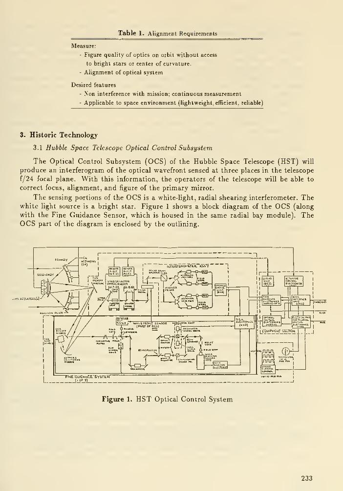
Table 1. Alignment Requirements
Measure:
- Figure quality of optics on orbit without access
to bright stars or center of curvature.
- Alignment of optical system
Desired features
- Non interference with mission; continuous measurement
- Applicable to space environment (lightweight, efficient, reliable)
3. Historic Technology
3.1 Hubble Space Telescope Optical Control Subsystem
The Optical Control Subsystem (OCS) of the Hubble Space Telescope (HST) will
produce an interferogram of the optical wavefront sensed at three places in the telescope
f/24 focal plane. With this information, the operators of the telescope will be able to
correct focus, alignment, and figure of the primary mirror.
The sensing portions of the OCS is a white-light, radial shearing interferometer. Thewhite light source is a bright star. Figure 1 shows a block diagram of the OCS (along
with the Fine Guidance Sensor, which is housed in the same radial bay module). TheOCS part of the diagram is enclosed by the outlining.
Figure 1. HST Optical Control System
233
The main telescope is shown in the upper left part of the diagram, and shows the five-
degree-of-freedom secondary mirror mount and the primary mirror with its twenty-four
figure control actuators. In operation, the image of a selected bright star is positioned on
the OCS pickoff mirror (lower left). The Hght from the star is collimated, after passing
through the astigmatism corrector plates and the field lens. The collimated beam is split
by the beam splitter. One of the beams is magnified by several diameters while the other
beam is demagnified by a similar amount. One of the two beams is then path-length
modulated by a set of oscillating optical wedges. The two beams are then combined at
the beam combiner, and relayed to an image dissector camera.
The interferometer reference beam is the larger of the two beams. In effect, a small
portion of the primary mirror (the enlarged beam) becomes the reference for the entire
mirror. The camera and signal processing electronics records the temporal phase (relative
to the modulator) of the interference pattern and transmits that data to the ground.
Further computer processing produces information about the state of focus, alignment and
primary mirror figure. It is expected this procedure will be followed weekly in the early
days of HST operation, and hopefully less frequently after favorable operating experience
is gained.
3.2 Sample Point Interferometers
In the late seventies, a patent for the sample point interferometer was granted to
Perkin Elmer. The purpose of the invention is to provide interferometric sensing of the
position and figure of a mirror segment from a convenient location, i.e. behind either the
secondary mirror or the primary mirror.
Figure 2, from the patent, illustrates the principle of operation. A mirror or a segment
of a mirror (item 21, upper diagram - "Fig. 1") for which the position and figure quality
is to be measured is fitted with a number of retrorefiectors about the size of an eraser on
a lead pencil. These retrorefiectors might be arranged as shown in the inset figure at the
right ("Fig.2"). A laser and lens arrangement (Items 10, 11, 12,20 and 22) illuminates the
mirror and the embedded retrorefiectors. The laser light reflected from the retrorefiectors
is combined with the light from the reference beam of the interferometer (item 15). The
optical path length of the reference leg is modulated by moving the end mirror (17). The
combined beams are detected by a photodetector array (item 18), where lens 22 produces
an image of the mirror.
For each retrorefiector (items 23a, 23b, and 23c), there is a detector. The electrical
signal output of these detectors is shown at the bottom ("Fig. 4"). If the optical path
length to the retrorefiectors is not exactly equal, a relative phase shift will occur as indi-
cated by item 25. It is this phase shift that is the desired measurement. Measuring phase
electronically is much more precise than measuring relative intensity, as in conventional
interferograms.
Since the wavelength of the laser light is accurately known, the measured phase shift
provides the mirror position actuator system with the signals needed to correct the po-
sition (or figure) of the mirror. Of course, the system must be initialized and calibrated
since it can only measure changes from the start position, and must make continuous
measurements and count waves to "remember" the initial position.
The center illustration ("Fig. 3") shows an embodiment where the laser and interfer-
ometer optics are conveniently located behind the primary mirror.
A number of alignment control systems have been built based on this patent. The
system is extremely sensitive and is able to control to about a hundredth of a wave.
234
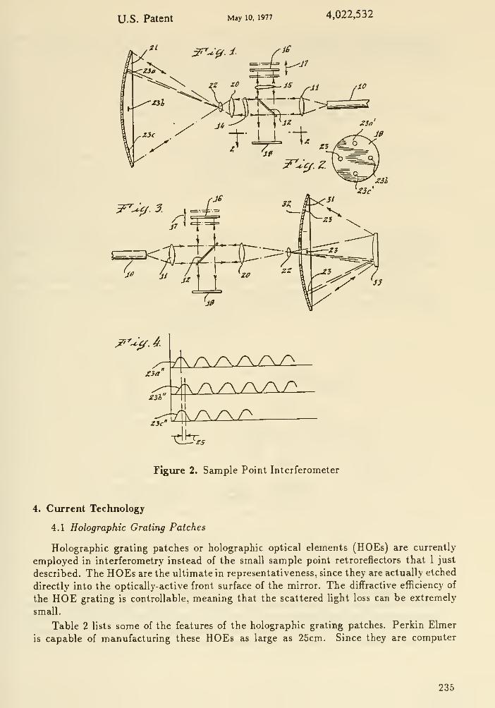
U.S. Patent May 10. 1977 4,022,532
X'^^^. ^
Figure 2. Sample Point Interferometer
4. Current Technology
4.1 Holographic Grating Patches
Holographic grating patches or holographic optical elements (HOEs) are currently
employed in interferometry instead of the small sample point retroreflectors that I just
described. The HOEs are the ultimate in representativeness, since they are actually etched
directly into the optically-active front surface of the mirror. The diffractive efficiency of
the HOE grating is controllable, meaning that the scattered light loss can be extremely
small.
Table 2 lists some of the features of the holographic grating patches. Perkin Elmer
is capable of manufacturing these HOEs as large as 25cm. Since they are computer
235

generated, they can be designed for any arbitrary mirror surface and can form an image
at any reasonably convenient place.
Table 2. Holographic Grating Patches
One hologram monitors mirror phase at each actuation
Each hologram acts as a retroreflector
Hologram is a phase-relief grating etched into mirror
Hologram is:
- computer generated
- fabricated locally on aspheric surface
- diffraction-limited quality
- controllable diffraction efficiency
- extremely low scatter
Figure 3 shows an application of the grating patch HOEs in the sample point inter-
ferometer application. They can also be used for alignment and focus monitors since the
image produced by diffraction is of extremely high quality, and is bright (virtue of the
laser illumination).
This technology is applicable to large optical systems having a smooth optical sub-
strate, and permits exceedingly precise, unambiguous, and rapid measurements of the
position and figure of the front surface of the mirror.
PRIMRY BIRROR SEOCTT
PHASE
REM HODIiATOR
EXPANDER
/ ll'lllllll N. N
LASER \ \ ^V^DETECTOR SECONDARY
ARRAY niRROR
Figure 3 Sample Point Interferometer using HOEs
4.2 Laser Radar
The Applied Science and Technology Directorate at Perkin Elmer has recently pro-
duced a unique and very simple laser radar capable of unambiguous absolute distance
measurements. The new laser radar incorporates a standard laser diode and an electron-
ics box that modulates the diode current and decodes the laser return. The principle of
operation is based on the fact that the backscatter from a target will form a front cavity
236

for the laser. Generally, the front cavity effect is unwanted, but in this application, the
front cavity is exploited to yield the desired distance information. Patents are pending at
Perkin Elmer, and journal papers are available describing the application. (See DeGrootet al, Applied Optics, Vol. 27, No. 21, Nov. 1, '88; and Optics Letters, Vol. 14, No. 3,
Feb. 1, '89)
Table 3 lists a number of applications for the laser radar. Of most interest to this
workshop is the "Optical Feedback Metrology Tool" item. The sub-micron metrology
application is applicable to rough as well as smooth surfaces.
We have presented to JPL the possible applications of laser radar for direct, front-
surface sensing for control of the Large Deployable Reflector (LDR) IR telescope that
Paul Swanson told you about earlier at this workshop. Table 4 lists some of the mainpoints that we made in our presentation.
The laser radar has been amply demonstrated in the laboratory and is ready for
various systems applications.
Table 3 - Laser measuring tools under development
High-power Coherent Laser Radar:
- 100 W mode-lokded diode array source
- km operational range
- Absolute range and velocity of high-speed objects
Backscatter Modulation Laser Radar:
- 0.5mW (eye safe) compact IR source
- 50 m operational range
- Absolute range and velocity with 1% accuracy
Short-range ranging and velocimetry instrument
- 5 mW UR source laser
-3m operational range
- Extremely compact, single and rugged design
- Both range and velocity to 1% accuracy
Optical Feedback Metrology Tool
- Sub-micron metrology of strongly aspheric optical surfaces
- Optical feedback geometry is compact and inexpensive
- Extrelmely aspheric surfaces can be accomadated
Position Tracking of Rotating Targets
- Compact, 1 mW IR source
- Tracks movement of rotating objects with 25 micron precision (0.001 inch)
- Can tolerate interupted beam and up to 1 mm/s displacements without ambiguity
- 50 cm operational range (can be extended?)
237
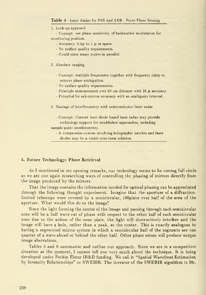
Table 4 - Laser Radar for PSR and LDR - Front Plane Sensing
1. Lock-up approach
- Concept: use phase sensitivity of backscatter modulation for
monitoring position.
- Accuracy: O.lfi to 1 /x in space.
- No surface quality requirements.
- Could sense many points in parallel.
2. Absolute ranging
- Concept: multiple frequencies together with frequency chirp to
remove phase ambiguities.
- No surface quality requirements.
- Principle demonstrated over 50 cm distance with 25 /x accuracy.
- Potential for sub-micron accuracy with no ambiguity interval.
3. Mariage of interferometry with semiconductor laser radar
- Concept: Current laser diode based laser radar may provide
technology support for established approaches, including
sample-point interferometry.
- A compromise system involving holographic patches and laser
diodes mav be a viable near-term solution.
5. Future Technology: Phase Retrieval
As I mentioned in my opening remarks, our technology seems to be coming full circle
as we are one again researching ways of controlling the phasing of mirrors directly from
the image produced by the mirrors.
That the image contains the information needed for optical phasing can be appreciated
through the following thought experiment. Imagine that the aperture of a diffraction-
limited telescope were covered by a semicircular, lOOplate over half of the area of the
aperture. What would this do to the image?
Since the light forming the center of the image and passing through each semicircular
zone will be a half wave out of phase with respect to the other half of each semicircular
zone due to the action of the zone plate, the light will destructively interfere and the
image will have a hole, rather than a peak, at the center. This is exactly analogous to
having a segmented mirror system in which a semicircular half of the segments are one
quarter of a wave ahead or behind the other half. Other phase errors will produce unique
image aberrations.
Tables 5 and 6 summarize and outline our approach. Since we are in a competitive
situation at the moment, I cannot tell you very much about the technique. It is being
developed under Perkin Elmer IR&D funding. We call it "Spatial Wavefront Estimation
by Intensity Relationships" or SWEBIR. The inventor of the SWEBIR algorithm is Mr.
238

Ed Siebert of P-E, and after all of his computer development is completed, I am sure
you'll be able to find future journal articles by Ed.
Table 5. Phase Retrieval
A family of mathematical approaches to determining optical
system figure errors from a star image
Equivalent in performance to a white light interferometer,
but without hardware
Can be used for figure capture and verification
Table 6. SWEBIR
Spatial wavefront estimation by intensity relationships
Computation of pupil function (figure and phase) from optical transfer function (OTF)
For point source (star):
- measure image (point spread function)
- compute Fourier transform to get OTF- apply SWEBIR
For extended source (known):
- measure image
- compute Fourier transform
- divide by Fourier transform of known source to get OTF- apply SWEBIR
SWEBIR is a very exciting development for large space telescopes since it promises
a very minimum amount of sensing hardware in the telescope: a single CCD (and a
computer). The computing requirements are not extraordinary.
6. Conclusion
A variety of technologies are available for the direct sensing and control of the large
telescopes of the future. These range from direct observation of a star image to interfer-
ometric measurements of the wavefront or, alternatively, sampled optical path length, to
laser radar.
239

DISCUSSION
Rehfield : Is SWEBIR applicable to high spatial frequency wavefront errors?
Wissinger: Yes. The spatial frequency bandwidth is governed by the size and density of the detector
array used to measure the PSF intensity.
Diner : I don't understand how you retrieve an OTF from the intensity image because you've lost
phase information.
Wiasinger: This is the purpose of phase retrieval. A comparison of algorithms is given by J. Fienup,
Applied Optics 21, 2758 (1982).
layman: Approximately what is time constant of a SWEBIR figure correction?
Wissinger: With a modest computer, the output should be expected in several seconds.
Vyee: Is the SWEBIR phase retrieval technique based on the 70s Gonzales' work more recently
updated by Jim Fienugo of ERIM?
l^singer: No. SWEBIR was developed at Perkin-Elmer.
240

Requirements for Diffraction Limited Optics
Christopher J. Burrows f
Space Telescope Science Institute
Abstract
We show that a ten meter 'diffraction limited' telescope can conduct a complete survey for a Jupiter-
like planet in a similar orbit around any of 20 or so stars closer than 5 parsecs. It will see at leeist one
planet in every close planetary system similar to ours. In addition to the scientific interest, such a survey
has great popular appeal, and should figure prominently in the justification for funding a Next Generation
Space Telescope (NGST) mission. If the telescope is capable of this very demanding mission, it will be
suitable for a wide variety of other scientific investigations.
Certain design constraints must be met for the survey. In particular, we show that 'diffraction
limited' means that both low and high spatial frequency errors on the wavefront are small in a definite
sense. Low frequency errors lead to a loss in resolution. High frequency errors lead to a loss in contrast.
A 10m telescope that is not diffraction limited in both respects will not be able to conduct a complete
survey. If the resolution is too low, the planet's image is smeared over too much stellar background signal,
while if the contrast is poor, the stellar background is raised.
Two areas of critical technology emerge from these considerations. First, for high contrast imaging,
fabrication and polishing techniques must be developed to yield smoother mirrors than those on HST.
Then the wings of a stellar image will be dominated by the intrinsic diffraction profile, which can be
largely removed by apodization. Second, for high resolution imaging, the conflicting requirements for a
large, lightweight, and fast primary mirror with an accurate figure mean that active optics will be needed.
We show that it will be hard to control the mirror surface with field stars. Either local sensing of mirror
displacements will be needed, or the mirror must be intrinsically stable to a fraction of a wavelength over
the full 10m aperture for a typical time of many seconds. This implies critical developments are necessary
in control and structure interactions.
1. Introduction
Presently there are no direct observational constraints on the probability of plane-
tary formation. The selection effects if we try to extrapolate from our own system are
formidable! A strongly positive or negative result from a survey would be of great philo-
sophical and scientific importance. Several schemes have been proposed for the detection
of Jupiter or Earth-like planets around nearby stars. It is important to ensure that any
search is complete over a substantial range of planet sizes, orbits (and temperatures), so
that even a negative result is significant.
In this paper we derive technical constraints for a 10 meter space telescope given the
specific scientific goal of conducting a meaningful survey for extrasolar planets. We show
in Section 2 that such a telescope, if diffraction limited can achieve the goal. In Section
3 we indicate how performance changes as the telescope degrades from the ideal, and weindicate technological problems that will need to be addressed to ensure that the required
image quality is achieved. The detailed discussion of the planet detection problem for the
Hubble Space Telescope (HST) given in Brown and Burrows (1989, hereafter referred to
as BE) is extended here to the proposed 10m aperture, and to include the effects of noise.
t Affiliated with the Astrophysics Division, Space Science Department of ESA
241
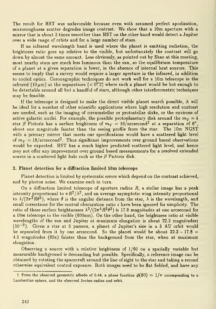
The result for HST was unfavorable because even with assumed perfect apodization,
microroughness scatter degrades image contrast. We show that a 10m aperture with a
mirror that is about 3 times smoother than HST on the other hand would detect a Jupiter
over a wide range of orbits and for a large number of stars.
If an infrared wavelength band is used where the planet is emitting radiation, the
brightness ratio goes up relative to the visible, but unfortunately the contrast will go
down by almost the same amount. Less obviously, as pointed out by Shao at this meeting,
most nearby stars are much less luminous than the sun, so the equilibrium temperature
of a planet at a given separation is lower, in the absence of internal heat sources. This
seems to imply that a survey would require a larger aperture in the infrared, in addition
to cooled optics. Coronagraphic techniques do not work well for a 10m telescope in the
infrared (lO/xm) at the separations (< 0'f2) where such a planet would be hot enough to
be detectable around all but a handful of stars, although other interferometric techniques
may be feasible.
If the telescope is designed to make the direct visible planet search possible, it will
be ideal for a number of other scientific apphcations where high resolution and contrast
are needed, such as the imaging of circumstellar or protostellar disks, or the environs of
active galactic nuclei. For example, the possible protoplanetary disk around the my = 4
star Pictoris has a surface brightness of my = IG/arcsecond"^ at a separation of 6",
about one magnitude fainter than the seeing profile from the star. The 10m NGSTwith a primary mirror that meets our specifications would have a scattered light level
of m,y = 18/arcsecond^. Thus significant improvements over ground based observations
would be expected. HST has a much higher predicted scattered light level, and hence
may not offer any improvement over ground based measurements for a resolved extended
source in a scattered Ught halo such as the (3 Pictoris disk.
2. Planet detection for a diffraction limited lOm telescope
Planet detection is limited by systematic errors which depend on the contrast achieved,
and by photon noise. We examine each in turn.
On a diffraction limited telescope of aperture radius R, a stellar image has a peak
intensity proportional to irRr/X^, and an average asymptotic wing intensity proportional
to X/{2ir^R9'^), where 9 is the angular distance from the star, A is the wavelength, and
small corrections for the central obscuration ratio e have been ignored for simplicity. Theratio of these surface brightnesses X'^/{2ir^R^d'^) is 17.8 magnitudes at one arcsecond for
a 10m telescope in the visible (600nm). On the other hand, the brightness ratio at visible
wavelengths of the sun and Jupiter at maximum elongation is about 22.3 magnitudesf
(10~^). Given a star at 5 parsecs, a planet of Jupiter's size in a 5 AU orbit would
be separated from it by one arcsecond. So the planet would be about 22.3 - 17.8 =4.5 magnitudes (60x) fainter than the background from the star, when at maximumelongation.
Observing a source with a relative brightness of 1/60 on a spatially variable but
measurable background is demanding but possible. Specifically, a reference image can be
obtained by rotating the spacecraft around the line of sight to the star and taking a second
otherwise equivalent control exposure. Both images need to be flat fielded, and have any
t From the observed geometric albedo of 0.44, a phase function ^(90) = I/tf corresponding to a
Lambertian sphere, and the observed Jovian radius and orbit.
242

distortions removed and the control image would need to be derotated before subtracting.
The stellar background should then almost exactly cancel. Sources of systematic error
(such as pointing and flat field errors) would need to be carefully controlled. BB (1989)
argue that for HST, such systematic effects hmit the relative brightness to at best about
1/100.
Photon noise, on the other hand is typically not a serious problem for the large
aperture, provided a wide bandpass is used (justifying our choice of the average wing
intensity above). In order to detect the planet, one can design an optimal hnear filter,
because the planet is unresolved so the expected signal is known, and the noise will
have Poisson statistics. Within 5 parsec, AUen lists 50 stars. Of these, 23 are membersof known multiple star systems and can probably be regarded as lower priority for a
planetary search. A further 5 stars are fainter than 12th magnitude. This leaves 22
candidates, with magnitudes approximately evenly distributed between 6th and 12th. In
only one hour, Jupiter 5 AU from an my = 6 candidate, contributes about 2 x IC* counts,
corresponding to a signal to noise ratio of S/N = 13 (assuming an overall efficiency of
0.5, a bandpass of AA/A = 0.5, and including noise from the reference exposure). If the
candidate star has my = 9 we would stiU have S/N = 3 in one hour, and even the faintest
candidates can be surveyed to this level in less than a day.f
A 3a- detection can be confirmed by examining the planet's rotated position - There
should be a corresponding negative signal there. It seems desirable to do the detection
in each channel separately to give a 'coincidence check', and hence eliminate problems
caused by cosmic rays, or bad pixels for example. A more detailed analysis of the detection
possibihties, including the effects of micro-roughness and apodization is given after their
effects are discussed in the next section.
3. Image quality
A telescope can be regarded as diffraction limited when the images that it gives are not
sensibly different from those obtained from a hypothetical perfect telescope of the sameaperture size, and overall efficiency. In the previous section, the performance of such
a hypothetical telescope was shown to be adequate for the planetary search problem,
but any significant drop in performance relative to this standard would make detection
impossible.
There are several different ways of faiUng to meet the 'diffraction limit': The aper-
ture configuration can be suboptimum, the mirror can be contaminated with particulates
(dust), the images can be distorted by aberrations, and the mirror surface can scatter
light. AU of these problems should be dealt with by careful attention in the design phase.
Their detailed effects are examined and compared to HST in the following four subsec-
tions. HST is used as a reference because it is the best we have without NGST, wecan learn from the experience in constructing it, and it was pushing the hmits of our
technology when constructed.
3.1 Pupil obscurations
The effect of small structures in the entrance pupil is to diffractively scatter light to
large angles. In the case of HST, the secondary mirror spiders will produce diffraction
t For reference, under the above conditions, the telescope's limiting magnitude is 34.5 in 1 hour for
S/N=3 with a detector read noise less than 3 e~ rms, and a background of my = 24/arc8econd'^.
243
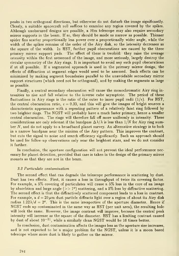
peaks in two orthogonal directions, but otherwise do not disturb the image significantly.
Clearly, a suitable spacecraft roll suffices to examine any region covered by the spikes.
Although unobscured designs are possible, a 10m telescope may also require secondary
mirror supports in the beam. If so, they should be made as narrow as possible. Thinner
spider fins scatter proportionally less power over a proportionally wider angle, while the
width of the spikes remains of the order of the Airy disk, so the intensity decreases as
the square of the width. In HST, further pupil obscurations are caused by the three
primary mirror support pads. The effect of these is twofold: they raise the average
intensity within the first arcsecond of the image, and more seriously, largely destroy the
circular symmetry of the Airy rings. It is important to avoid any such pupil obscurations
if at all possible. If a segmented approach is used in the primary mirror design, the
effects of diffraction at segment edges would need to be assessed. Such effects can be
minimized by making segment boundaries parallel to the unavoidable secondary mirror
support structures (which need not be orthogonal), and by making the segments as large
as possible.
Finally, a central secondary obscuration will cause the monochromatic Airy ring in-
tensities to rise and fall relative to the inverse cube asymptote. The period of these
fluctuations in Airy rings is the ratio of the outer to inner pupil radii (1/e). For HST,the central obscuration ratio, e = 0.33, and this will give the images of bright sources a
characteristic appearance with a repeating pattern of a relatively faint ring followed by
two brighter rings. The NGST will probably have a much faster primary, hence a smaller
central obscuration. The rings will therefore fall off more uniformly in intensity. These
considerations are only relevant if the bandpass AA/A is less than IjN for Airy ring num-
ber AT, and do not apply to a broadband planet survey. An alternative strategy is to look
in a narrow bandpass near the minima of the Airy pattern. This improves the contrast,
but cuts the signal to noise and search efficiency significantly. Such an approach should
be used for follow-up observations only near the brightest stars, and we do not consider
it further.
In conclusion, the aperture configuration will not prevent the ideal performance nec-
essary for planet detection, provided that care is taken in the design of the primary mirror
mounts so that they are not in the beam.
3.2 Particulate contamination
The second effect that can degrade the telescope performance is scattering by dust.
Dust has two effects. First, it causes a loss in throughput of twice its covering factor.
For example, a 5% covering of particulates wiU cause a 5% loss in the core of an image
by absorbtion and large angle (>> 1") scattering, and a 5% loss by diffractive scattering.
The second effect is that the diffractively scattered component leads to a loss in contrast.
For example, a d = 20 /im dust particle diffracts fight over a region of about its Airy disk
radius \.22\jd = 2°. This is the same irrespective of the aperture diameter. Hence if
NGST ends up contaminated in the same way as HST (per unit area), the resulting halo
will look the same. However, the image contrast will improve, because the central peak
intensity will increase as the square of the diameter. HST has a fimiting contrast caused
by dust of about 10~^^, while a similarly clean NGST would be 16 times better.
In conclusion, dust contamination affects the images less as the aperture size increases,
and is not expected to be a major problem for the NGST, unless it is a moon based
telescope where more dust is fikely to gather on the mirror.
244

3.3 Mirror figure errors
One effect of wavefront errors on the image is to lower the central peak intensity.
The central intensity drops by the Strehl factor (5 = exp(-47r^<T^/A^)) for a small root
mean square (rms) wavefront error a, or if the wavefront error is large but occurs at high
frequencies in the pupil, and has Gaussian statistics. If a 20% drop in peak intensity
is regarded as acceptable, then the equation can be solved to show that a must be less
than A/ 13. For larger wavefront errors, the peak intensity falls rapidly, and the desired
survey would be impossible. The important point is that alignment and microroughness
errors will also contribute to this total, so the primary mirror surface figure will need
to be maintained to about A/40 rms f, over the entire aperture. This is a demandingspecification and corresponds approximately to the performance of the HST primary. It
is an order of magnitude more stringent than a typical groundbased telescope mirror
specification. Furthermore it seems clear that the primary wiU need to be perhaps as fast
as Fp = 1.2 and lightweight for packaging reasons.
Nobody has proposed a method of building such a monolithic 10m mirror that will
passively retain its shape to this accuracy. Existing proposals generally involve either
segmented, or meniscus construction, with an active control system. In each case, a
characteristic length scale (either the segment size or the distance between actuators)
is typically about Im. Larger scales lead to tight positional tolerances on segments, or
unacceptably thick membranes.
Specifically, if a segment is moved away from the mirror center, the rms wavefront
residual after best correction for tilt and piston can be shown to be proportional to the
radial displacement, the square of segment radius, and inversely proportional to the full
aperture baseline squared, and F/ratio of the primary {Fp) cubed. A detailed calculation
shows that for A/20 wave rms at 500 nm and Fp = 1, any radial displacement must be
less than 7.5 fim for one meter segments. If this degree of freedom is to be passively
controlled, (as in the Keck telescope), it is clear that the segments cannot be much larger.
A wavefront tilt can be estimated to an accuracy of X/n if at least n^ photons are
detected|. Furthermore, the correctable field size of the telescope is limited to about a
radius of 2J\Fp/D where the astigmatism of a Ritchey- Chretien Cassegrain becomes one
wave. The field must be fuUy corrected or cahbrated in order to be useable for wavefront
measurements, so this seems a realistic bound on the achievable field.
For the 10m Fp — 1 system we need a guide star density of 400 per square degree in
order to get one in the field on average. Over much of the sky (away from the galactic
plane) this means that guide stars will be 18th magnitude or fainter. It takes 1 second to
collect 400 counts from an 18th magnitude star with a Im aperture (assuming an efficiency
of 0.5 and a bandpass of 200nm). On the other hand, over the full aperture one collects
enough light for overall pointing in about 10ms.
In conclusion, if the mirror surface is to be actively controlled in tilt, and field stars
are to provide the position feedback, any disturbances must be less than 1/40 wave over
timescales of several seconds over the full 10m aperture. The effects of any gravitational,
ram pressure, thermal, and magnetic perturbations would all need to be shown to be
below these levels over such timescales. Clearly, such a control system could not take out
t Corresponding to an rms wavefront error of A/20
t This follows if one considers the Cramer Rao bound for estimating the phase of fringes a =Tl~^/(1 — V 1 — M^) for fringe contreist M, or the statistical errors in a centroid.
245
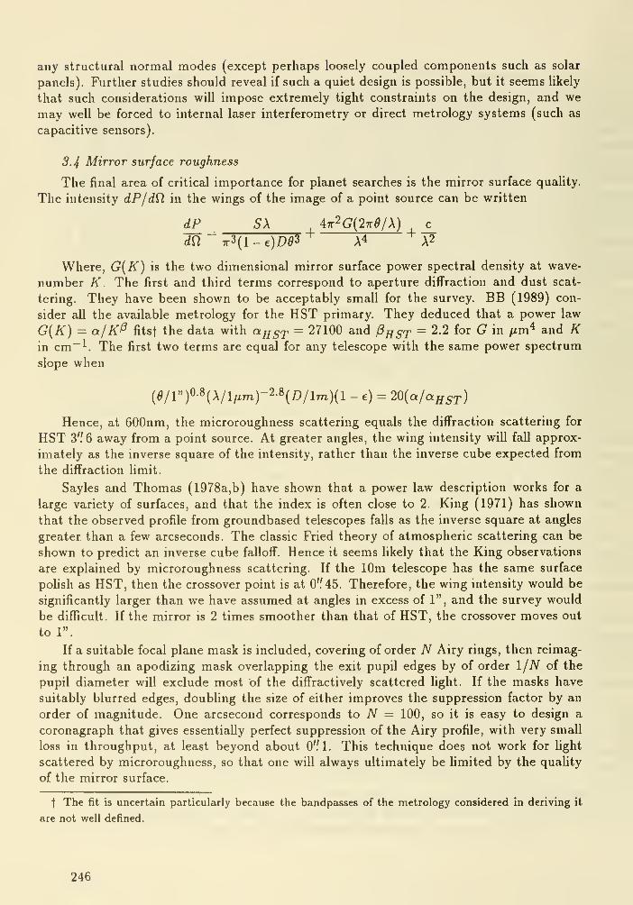
any structural normal modes (except perhaps loosely coupled components such as solar
panels). Further studies should reveal if such a quiet design is possible, but it seems likely
that such considerations will impose extremely tight constraints on the design, and we
may well be forced to internal laser interferometry or direct metrology systems (such as
capacitive sensors).
3.4 Mirror surface roughness
The final area of critical importance for planet searches is the mirror surface quality.
The intensity dP/dQ in the wings of the image of a point source can be written
dP _ SX 47r2g(27rg/A) c
dfi "7r3(l-e)D^3+ X^ X^
Where, G{K) is the two dimensional mirror surface power spectral density at wave-
number K. The first and third terms correspond to aperture diffraction and dust scat-
tering. They have been shown to be acceptably small for the survey. BB (1989) con-
sider all the available metrology for the HST primary. They deduced that a power law
G{K) = a/Kf^ fitsf the data with aggj^ = 27100 and /3^5y = 2.2 for G in /xm^ and Kin cm~^. The first two terms are equal for any telescope with the same power spectrum
slope when
(5/l")0-8(A/l,xm)-2-8(I»/lm)(l - e) = 20{a/aHST)
Hence, at 600nm, the microroughness scattering equals the diffraction scattering for
HST 3" 6 away from a point source. At greater angles, the wing intensity will fall approx-
imately as the inverse square of the intensity, rather than the inverse cube expected from
the diffraction limit.
Sayles and Thomas ( 1978a, b) have shown that a power law description works for a
large variety of surfaces, and that the index is often close to 2. King (1971) has shown
that the observed profile from groundbased telescopes falls as the inverse square at angles
greater than a few arcseconds. The classic Fried theory of atmospheric scattering can be
shown to predict an inverse cube falloff. Hence it seems Ukely that the King observations
are explained by microroughness scattering. If the 10m telescope has the same surface
pohsh as HST, then the crossover point is at 0'.'45. Therefore, the wing intensity would be
significantly larger than we have assumed at angles in excess of 1", and the survey would
be difficult. If the mirror is 2 times smoother than that of HST, the crossover moves out
to 1".
If a suitable focal plane mask is included, covering of order N Airy rings, then reimag-
ing through an apodizing mask overlapping the exit pupil edges by of order 1/A^ of the
pupil diameter wiU exclude most of the diffractively scattered fight. If the masks have
suitably blurred edges, doubfing the size of either improves the suppression factor by an
order of magnitude. One arcsecond corresponds to N = 100, so it is easy to design a
coronagraph that gives essentially perfect suppression of the Airy profile, with very small
loss in throughput, at least beyond about O'.'l. This technique does not work for fight
scattered by microroughness, so that one will always ultimately be fimited by the quafity
of the mirror surface.
t The fit is uncertain particularly because the bandpasses of the metrology considered in deriving it
are not well defined.
246

If the mirror polish power can be improved by about a factor of 2 (a factor of 1.4
in amplitude) on the relevant scales (1-10 cm), over that predicted for HST then the
planet search is feasible. An order of magnitude improvement would be desirable because
both contrast and signal to noise would improve correspondingly, leaving more margin for
error and a smaller planet would be detectable. Such a specification is reasonable. There
are indications that the HST primary is not as good as some ground based telescopes in
this respect. The specifications on the secondary pohsh can be about 1/e less stringent,
because the beam diameter is smaller on the secondary.
Microroughness imposes a practical hmit on contrast. A goal should be to fabricate
a mirror that has a surface that is 3 times smoother in amplitude than the HST primary.
The telescope would then be 'diffraction Umited' out to 8 arcseconds from a bright source.
4. Planet detection with apodization and microroughness present
If the specifications developed in Section 3 are met, a Jupiter-like planet would be
detectable at 5 AU, from any of about 20 stars at 5 parsec. Some of the 20 candidates
are in fact closer, or the planet may be at a different distance from the star. Therefore,
we consider the effects of the angular separation explicitly here, and combine the effects
of signal to noise and contrast Umitations to derive the available search space.
First, if the star is closer, but the planet is assumed to be in the same radius orbit,
the apparent angular separation increases linearly, so the contrast will go up as the the
inverse square or cube of the distance (depending on whether one is microroughness or
Airy diffraction limited). So we are considering a worst case by assuming all the candidates
are at their maximum distance.
Second, if the planet orbit is changed but for a fixed distance to the star, the planet
brightness decreases quadratically with angular separation. Thus, in the diffraction hmit
one gets a Unear growth in the ratio of the planet to stellar surface brightness with
increasing angular separation, until the image becomes dominated by sky background
(or other effects such as microroughness scattering). For a star with my — 6 the profile
remains brighter than a sky brightness of my = 24/arcsecond^ out to a separation of
15". For m,y = 12 the sky is reached at 2". The planet at 15" is 5.9 magnitudes fainter
than at 1", so a Jupiter-hke planet at 15" from a 6th magnitude star at 5pc would have a
brightness of 6 + 5.9 + 22.3 = 34.2. A detection should be possible throughout the range
1" to 15" and is Umited at the low end by low contrast and systematic errors, and at
the high end by poor signal to noise. On the other hand, in the region where the image
is microroughness limited, the ratio of the planet to stellar surface brightness will be
constant, until the sky brightness becomes the limiting factor. In this case, one is limited
by signal to noise for short exposures (one hour), but by contrast for longer exposures (10
hours). The microroughness hmit will be reached if a suitable coronagraph is used.
AU of these considerations are illustrated in Figure 1, which shows the available search
space both with and without microroughness scattering. The area indicated as feasible
apphes to the detection of a Jupiter-hke planet in orbit around a star at 5 parsec. There-
fore, angular separations in the Figure correspond numerically to the size of the orbit
relative to Jupiter's. The grey area defining the hmits of detectability corresponds to a
signal to noise in the range 2 to 4 and a contrast in the range 1/64 to 1/128. For the
bottom panels, all the Airy profile contribution is assumed removed by apodization, and
the microroughness scatter is taken to be a factor of 2 better than that predicted for HST(although we recommended a factor of 9 in Section 3).
247

Diffroction limit -1 hour
0.1 1.0 10.0
Angular Separation (orcsec)
Diffraction limit - 10 hours
(U
V3
1
9 8
Cl
<
m&^w0- iliiliinsj:
61
0. 1.0 10.0
Angulor Separation (orcsec)
Microrouqhness - 1 hour Microrouqhness - 10 hourm 1 , < ,, 1 , .». —, ..v.-' '
I 'M I J ' ' '' J. ' iit i
.........'.*. :j
: i:.ms.- ' -.'.-.'.m
0.1 1.0 10.0
Angular Seporation (orcsec)
u34-'
c01
D
C(U
L
Q.
a<
10
6
0.1 1.0 10.0
Angular Seporation (orcsec)
Figure 1: Feasible search space in white, as a function of the star's apparent magnitude, and
the angular separation from it of a Jupiter-hke planet. The panels correspond to 1 and 10
hours of integration, when limited by diffraction or microroughness. The dotted contours
map the signal to noise ratio, while the solid contours correspond to contrast.
248

5. Conclusions
A 10m diffraction-limited telescope can directly detect a Jupiter sized planet at 5
parsecs, where over 20 single candidate stars are available for a survey. The planet would
be detected when it passes through maximum elongation if it is at least 5 AU and less
than about 50 AU from the brighter stars. Therefore, even a non-detection would be a
scientifically valuable result, provided synoptic observations cover half the orbital period
(6 years for Jupiter around one solar mass). If a coronagraphic camera is used the planet
would be detectable throughout most of the orbit.
Conversely, a significant decrease in the peak intensity, or increase in the wing intensity
would make this experiment impossible with a 10m aperture. In the microroughness
hmit, increasing the aperture size improves the contrast ratio as the square. Although
the experiment is feasible with a 10m mirror that is a factor of 2 smoother than the
HST primary, an order of magnitude improvement would vastly improve the results, and
expand the search space. A significantly smaller aperture, even if made proportionally
smoother would suffer from severe signal to noise problems for the survey considered here.
Planet searches are not the only scientific driver for the development of the NGST,but the goal has great popular appeal, and should figure prominently in the justification
for funding such a mission. Furthermore, as we have shown, mission requirements flow
naturally from such a goal, in areas as diverse as aperture configuration, mirror quality,
pointing stability, detector performance, and mission lifetime.
If these ambitious goals can be met, other scientific projects requiring high contrast
and resolution, and accurate reproducable pointing, would of course also benefit. HSThas a much higher predicted scattered light level, and hence may not offer any improve-
ment over ground based measurements for a resolved extended source in a scattered hght
halo such as the (3 Pictoris disk. The NGST will provide us with higher resolution and
sensitivity. With careful design it will also provide higher contrast. Such image quality is
vital for the appUcation that may be a primary driver for the development, and will also
serve well in other investigations.
Acknowledgements
It is a pleasure to thank Robert Brown and Pierre Bely for many useful discussions,
and Jan Koornneef for a careful reading of the manuscript.
References
Brown, R. A. and Burrows, C. J., 1990. Icarus, Submitted
Sayles, R. S. and Thomas, T. R. 1978a. Nature, 271, 433
Sayles, R. S. and Thomas, T. R. 1978b. Nature, 273, 573
King, I. 1971. Publ. Astron. Soc. Pacific, 83, 199
249

DISCUSSION
Angel: I have a comment relating to on-board metrology using guide stars. The situation is easy
compared to doing adaptive optics on the ground. You can take stars at much larger angles if you
use something like a Hartmann test, for example. You know what the aberrations are going to be
at large fields. So once you have made a calibration, you can either do it by calculation or explicitly
with the telescope. It seems to me that fields up to several arcminutes are quite feeisible, because the
aberrations will still be such that a Hartmann test will work. You can use brighter stars from a wider
field because wavefront distortion of the guide star can be quite large.
Biirrows : My main object in identifying the guide star problem is to bring it to people's attention. The
field can no doubt be enlarged somewhat with corrective optics. However, the uncorrected aberrations
increase as the square of the field angle, and I have already assumed that they can be calibrated or
corrected to something like A/20 over a field where they are as large as one wave. It is an order-of-
magnitude calculation. The problem that I have is that even if you make it a 5 arcminutes or 10
arcminutes field you still need an extremely quiet structure over long periods. Furthermore, for many
active optics concepts, people talk about correcting over diameters that are much smaller than a meter.
I agree that one can push any of the individual eissumptions but we will need to push several of them
at once. It seems to me that it will be extremely challenging to do that. So perhaps we will need
instead to put effort into developing on-board metrology that will make the structure rigid internally
without external references.
Breckinridge: Is there an observing program to take place during the flight of the Space Telescope
which will measure the performance and the performance degradation of large mirrors in space for the
purpose of planet detection and characterization?
Burrows : Yes. One of the Observatory level tests to be conducted during the Science Verification
period is specifically designed to measure the wings of the point spread function out to about 12 arcsec.
These wings provide the background against which any planet must be detected. The mirrors are not
expected to experience degradation on orbit at length scales of centimeters, and so the performance in
this region is not expected to change. It will be monitored with the science instruments as the mission
progresses. It will be interesting to compare the results of this test with predictions made on the
bcisis of the pre-launch metrology. I know of no case of a mirror where there is both well-established
metrology and good measurements of the profile. So maybe we have to be careful when saying that we
understand the wing profile. HST may be the first case where both of these measurements are done.
niingworth : The timescales and size scales (Is and Im) that can be constrained with the signal from
an 18th magnitude star do not seem to me to necessarily be a severe problem - But I would appreciate
some feedback from the speaker and the audience on this!
Burrows : The 1 m constraint seems reasonable from stiffness and weight considerations. The 1 second
constraint is much harder to justify, and I have identified it as an area for further work. Clearly, thermal.
250

gravitational, magnetic and possibly atmospheric drag stresses become relevant on these timescales in
addition to mechanical normal modes that may be excited in the structure by the pointing system in
response to those perturbations.
Layman: The 1 second sample time calculated for A/20 position measurement accuracy (18 mag star,
Im^ surface area) would permit no more than approximately 0.1 Hz control bandwidth.
Burrows : One would need to be concerned if the area to be controlled was less than a meter, such as
might be required for a meniscus of for small segments.
Unidentified : A comment of on the dust coverage. For AXAF the end- of-life budget for coverage is
5 10"^. As you noted, dust only affects the Airy profile at large radii, but it still matters.
Burrows : Dust has been a serious concern for the HST project, and the measured 2% coverage is
expected to increase by 1% or so during launch. For a given dust distribution, larger apertures have
less contrast degradation.
Angel: For a telescope on the moon one can dump the vibrational energy into the ground. The moon
also has the great advantage of lacking the exciting mechanisms (e.g., wind) that cause us so much
trouble on earth. For a spacecraft you need to avoid vibrational frequencies which are higher than
some critical frequency. So you have to think about what is going to excite it, and how quickly you
can dump it.
Stockman : I believe I can comment on Roger Angel's question about how vibrations are damped
in space. On HST, the structure is made extremely stiff so that all natural frequencies are above 10
Hz. However, the solar arrays have very low frequencies (about 0.2 Hz) and their effects and slow
thermal effects are removed by the pointing control system. The Pointing Conrol System and all other
disturbances are controlled or damped to minimize the excitation of high frequency modes.
251

Precision Segmented Reflectors (PSR)
Richard Y. LinJet Propulsion Laboratory
PSR PROGRAM
• AN ELEMENT OF CIVIL SPACE TECHNOLOGY INITIATIVE (CSTI)
• OBJECTIVES
• DEVELOP ENABLING TECHNOLOGIES FOR LARGE LIGHTWEIGHT SEGMENTEDREFLECTOR SYSTEMS FOR SPACE APPLICATIONS
• VALIDATE TECHNOLOGIES BY MEANS OF A SYSTEM DEMONSTRATION
• APPROACH
• FOCUSED DEVELOPMENT• SOME ADVANCED RESEARCH• WILL SERVE AS A FUTURE TECHNOLOGY TEST BED
• JOINT OAST & OSSA PROGRAM: MANAGED BY OAST
• PARTICIPATING CENTERS
• JPL & LaRC, WITH JPL LEAD
• RESOURCES
~ $20M
• FOUR YEARS PROGRAM• FY'88 - FY'91
• PROGRAM COMPLETION CAN BE EXTENDED
• 4 MAJOR ELEMENTS
252
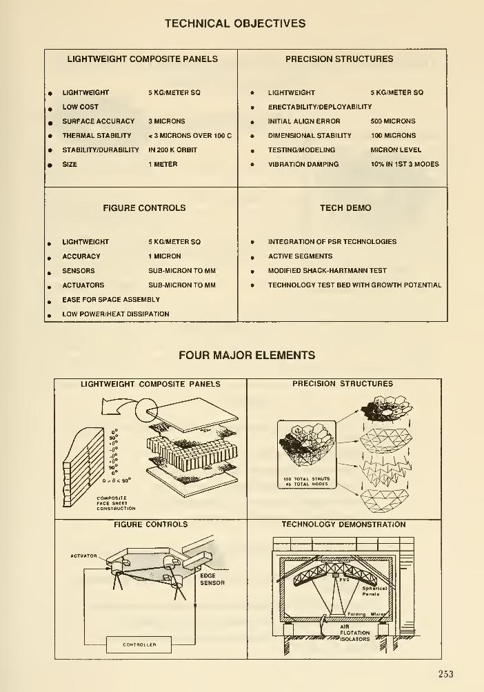
TECHNICAL OBJECTIVES
LIGHTWEIGHT COMPOSITE PANELS
• LIGHTWEIGHT 5 KG/METER SO
, LOW COST
» SURFACE ACCURACY 3 MICRONS
• THERMAL STABILITY < 3 MICRONS OVER 100 C
• STABILITY/DURABILITY IN 200 K ORBIT
• SIZE 1 METER

TWO-RING ERECTABLE PRECISION SEGMENTED REFLECTOR(Tetrahedral Truss Design)
^iiiiittglJi^ji/itiiiigtjtg^gtimtmimiimmimMtimm^
150 Total Struts
45 Total Nodes
Reflector Panels with StandoHs(18 panels, 27 standoffs)
Upper Primary Truss Surface
(60 struts, 27 nodes)
Core of Primary Truss(54 struts)
Lower Primary Truss Surface(36 struts, 18 nodes)
SUMMARY
Current PSR technology development Is intended for LDR-likeapplications:
• Large segmented reflector systems
• Lightweight composite panels at 3 ^m RMS• Precision lightweight structure at 500 |im
• Active figure control at 1 ^m RMS accuracy
• 5 ^m RMS overall surface accuracy
Development of PSR technologies to date has demonstrated thepotential of:
• Lightweight composite panels at 0.1 |xm RMS via polishing &re-finishing
• Shape control of composite panels by imbeded actuators
• Precision lightweight structure at 100 |im or better
• Smart structure strut that can suppress vibrations andchange its length
254

DISCUSSION
Nelson : What limits the stability of the stiuctute? You have 100 microns at an estimate. Is it water
outgassing or thermal variability? What might you expect for a 10-16 meter space telescope structure
like this?
Im : In the development of space structures, one of the key components are the joints. Currently
these are aluminum which has a large coefficient of thermal expansion compared to graphite epoxy.
So we are interested in pushing that joint design towards titanium, for example, which has a much
smaUer coefficient of expansion, or even graphite epoxy. But the challenge is how does one design a
structure that is lightweight, but also at the same time does not have hysteresis, non-linearity or free
play. That is our challenge.
Unidentified : Have you done any testing of these structures at cryogenic temperatures?
lin : First, we have done about a dozen tests on the panels, one being a low temperature test in a
thermal vacuum chamber. It was done with a goal of calibrating the overeill system, and so it wasn't
really intended to get the low temperature performance of the panels. But we believe that at the low
temperatures, about 200''K, that the surface accuracy changes would be about 5-6 microns rms. This
is from analysis. In addition, we are in the process of carrying out actual tests. We have, however,
done a lot of low temperature testing in the materials area using coupons. This materials development
is being done in parallel and one can do a lot very useful testing using coupons.
255

ASCI£: An Integrated Experiment to Study Control Structure Interaction
in Itirge Segmented Optical Systems
by Jean-Noel Aubrun and Kenneth R. Lorell
Lockheed Palo Alto Research Laboratory
Large segmented reflector systems
The use of a segmented primary mirror is one of the major design concepts for the new
generation of large ground and space-based telescopes. The W. M. Keck Ten-Meter Tele-
scope (TMT), or NASA's planned Large Deployable Reflector (LDR) are typical examples
of this approach.
In a segmented reflector the mechanical rigidity and geometric aecuracy are supplied
solely by the support structure. Imperfections in the manufacturing process, deformations
due to gravity loads, thermal gradients, slewing and tracking dynamics, and structural
vibrations make it imperative that the positions of the segments be actively controlled.
For example, the TMT segment alignment system requires 162 sensors, 108 actuators,
and a special control system to align its 36 segments.
An important characteristic of such systems is that the supporting truss is very light
(even for ground-based telescopes like the TMT), thus very flexible, with usually low
natural damping. As a result, interactions between the segment alignment control system
and the structural dynamics are expected to occur.
Motivation for the development of an integrated experiment
The interaction between the control system actuators and sensors with the dynam-
ics of the supporting structure seriously limits the performance of the system. A recent
analytical study done by Lockheed [refs 1, 2 and 3] of the TMT that modelled the full
structure, actuator and sensor set, and control system operation showed that control sys-
tem stability was seriously affected by dynamic coupling between the segments through
the support structure. Tests performed on a single segment and support cell conducted
at the Lawrence Berkeley Laboratory failed to predict this phenomenon because they did
not account for the effects of collective motion and coupling in the full system. While
analysis can be very effective in predicting major behavior, there are numerous practi-
cal problems that must be solved and tested with real hardware. Moreover, the design
and implementation of a multi-actuator, multi-sensor control system for large flexible
segmented reflectors (LFSR) has never been experimentally validated. There was thus a
need to develop a test bed that could support strong interdisciplinary studies to develop
and validate the emerging LFSR technology.
ASCIE Objectives
A uiuque ground experiment called the Advanced Structures/Controls Integrated Ex-
periment (ASCIE) has been conceived and developed as a means of performing meaningful
laboratory experiments for the design, implementation, and validation of control strate-
gies for large flexible systems with distributed optical elements, and in particular for large
256

segmented telescopes. The ASCIE test bed has been designed to support a number of
interdisciplinary studies that address major technical challenges of LFSRs. One of the
immediate objectives of this project concerns the study of structures/controls interaction
in LFSRs. However the scope of ASCIE is of a more general nature. Topics such as
structural control (e.g. active damping, vibration suppression, disturbance alleviation)
or pointing and slewing techniques for LFSRs wiU also be addressed using the ASCIESystem.
The near-term goal for the ASCIE is to demonstrate in the laboratory a fully operating
TMT-like segment alignment control system with a level of performance comparable to
that required for a real telescope. This study will provide a means to investigate the CSIphenomenon in a real structure and compare it to analytical predictions. Longer termgoals include substantial improvements in bandwidth and disturbance rejection through
the use of advanced control techniques.
ASCIE Features
The ASCIE structure shown in Fig. 1 consists of a 2-meter, 7-segment actively con-
trolled primary mirror supported by a light, flexible truss structure. The optical system
emulates that of an f/1.25 Cassegrain telescope and utilizes an actively controlled sec-
ondary mirror. The six peripheral segments are controlled in three degrees of freedom
using specially developed precision actuators. Segment alignment is obtained through the
use of edge sensors whose signals are processed by the control system which then generates
the commands for the actuators. One of the unique features of the ASCIE is its optical
scoring and calibration system which eliminates the requirement that the segments have
real optical surfaces. Small optical flats combined with a special faceted secondary mirror
reflect laser beams onto an array of linear position-sensing photodetectors.
SEGMENTED PRIMARY
Figure 1
SIMULATEDSECONDARY
OPTICALMEASUREMENTSYSTEM FORCALIBRATIONAND SCORING
6 ACTIVELYCONTROLLEDSEGMENTS
EDGE SENSORSFOR ACTIVEALIGNMENT
LIGHTWEIGHT TRUSS
The active control of the secondary mirror is necessary to provide correct initial align-
ment of the primary segments. It will also be used to improve image stability and to
simulate a chopping secondary, a feature found in all infrared astronomical telescopes
[Refs 4 and 5]. Controlling the secondary mirror to stabilize the image at the focal plane
is another example of a non-collocated system where CSI pays an important role [Ref 6].
257

ASCIE structure dynamics properties
The ASCIE structure was designed to replicate the complex dynamic behavior that
characterize large segmented systems. Typical of such systems is the modal grouping due
to the high degree of symmetry of the structure. For a perfectly rigid support structure,
the segments and their supporting mechanisms (e.g. subcell and actuators) have almost
identical dynamic properties and thus can be viewed as N identical oscillators at the
same frequency. For ASCIE 18 modes of vibration related to the segments will occur at
more or less the same frequency. However, because the support structure is in reality quite
flexible, coupling between the grouped oscillators produces two results. First, the resonant
frequencies tend to spread slightly by moving away from each other [Ref 7]. The second,
and more significant effect in terms of CSI, is the creation of global or collective modes
in which the segments as a whole behave as a continuous sheet rather than as individual
pieces. These modes effectively couple one part of the mirror to another, creating adverse
interactions that did not exist when considering individual segment dynamics. Fig. 2
shows a comparison between the modal frequency histograms of ASCIE and of the Keck
telescope. A great similarity can be observed. This behavior is quite different from that
of a beam-like structure as also shown on the figure. In addition the ASCIE structure
was tuned to have its significant modes around 12-15 HZ to be relevant.
120-
90 -
>UzDoUJ
LOCKED ACTUATORMODES
FREE ACTUATORMODESJ I
20
MODE NO.
a. ASCIE
60 30 60 90 120 150 180
MODE NO.
b. Histogram of TMT Modal Frequencies
120
>ozUJDoUJE
Figure 2
10 IS 20
MODE NO.
25
c. Cantilever Beam
258

ASCIE Control system principle
The segment alignment control system is similar to that of the Keck telescope. It
utilizes a self-referenced system of edge sensors providing a set of error signals that are
processed through a special algorithm to obtain the piston and tilt errors for each individ-
ual segment. Corrections based upon these errors are applied, through proper electronic
compensation, to the actuators controlling position and tilt of each segment (Fig 3). In
such a centralized control system where the actuators are driven by signzds from all the
sensors, structural dynamics can couple the actuators to all the sensors through global
modes of vibration, thus resulting in potential instability.
MIRBOBSEGMENT
Figure 3

ASCIE optical caUbration and scoring system principle
Fig. 5 shows the principle of an optical system that directly measures the tilt errors
associfted with each segment. It emulates a more comp ex^-^J-^^J-Xe refer^^^^^^^
holographic patches, for example. The laser beain commg from the -"^^^l^^^;f^^^^^^
is split into six equal beams by a special faceted secondary mirror. Each of the beams
efle ts on a mi flat mounted on the corresponding segment reflects back on the same
acet of the secondary mirror and finally focuses on a two-axis photodetector. The pho
todetector provides two electrical signals directly proportional to the position of the laser
spo in two orthogonal directions. This optical system has a sensitivity o 0.1 arcsecond
and i^used to initially align the segments. After this operation the -Uol sy^em r.
members the set points of all the edge sensors and maintains them in the Presence of
^ilt^rbances. The optical system is not a part of the control loop but can be used as an
hldependent .coring'system to evaluate the performance of the segment alignment control
system.
Figure 5
- CENTRAL SEGMENT
ASCE single element alignment test (piston and tilt errors)
The segment aligment errors during closed-loop operations are shown in Fig. 6a for
piston, and in Fig. 6b for the two tilt axes ("Petal" denotes a folding motion of the
segments toward the optical axis). The residual error is due essentially to seismic andsensor noise. By contrast with the previous plot, the traces are here perfectly centered,
i.e., the thermal drift has been completely eliminated. The level of performance that
has been achieved (about 30 nm rms in piston and less than 0.05 arcsecond in tilt) is
150
100
-50
-100
-150
-200
il
:i0f->rf§mf
260
2.5
TIME (s)
Piston error
Figure 6a
5.0
250
-250
250
-250
., ; 1. 1 ..
,
».'&%:^\^^^lfPETAL
_.•,. . fr
•••f.;'. 'IV
'•( I
TWIST
2.5

comparable to that of the Keck telescope requirements and thus represents a major step
in validating the technology for large flexible segmented optical systems.
Conclusions
This paper has presented a description of the ASCIE experimental setup, a generic
test bed for several essential technologies. In particular its multi-input, multi-output,
non-collocated control system and its complex structural dynamics, characteristic of large
segmented systems make it an ideal test bed for CSI experiments. The high accuracy of its
measurement system will make it possible to investigate the dynamics of microvibrations
and its implication for thie CSI phenomenon.
References
1. Aubrun, J-N, Lorell, K.R.,Havas, T.W., and Henniger, W.C: An Analysis of the
Segment Alignment Control System for the W- M. Keck Observatory Ten Heter Tele-
scope. Final Report. Keck Observatory Report Number 143, Dec 1985
2. Aubrun,J-N., Lorell, K.R.,Mast, T.S., and Nelson, J.E.: Dynamic Analysis of the
Actively Controlled Segmented Hirror of tne W. M. Keck Ten Meter Telescope. IEEEControl Systems Magazine, Vol. 7, No. 6, Dec 1987
3. Aubrun, J-N, Lorell, K.R., Havas, T.W., and Henniger, W.C: Performance Analysis
of the Segment Alignment Control System for the Ten-Heter Telescope. AUTOMAT-ICA, Vol. 24, No. 4, Jul 1988
4. Sridhar, B.,Lorell, K.R., and Aubrun, J-N.: Design of a Precision Pointing Control
System for the Space Infrared Telescope Facility. IEEE Control Systems Magazine,
Vol. 6, No. 1, Feb. 1986
5. Lorell, K.R. and Aubrun, J-N.: Active Image Stabilization for Shuttle-Based Pay-
loads. Proceedings of the 1986 American Control Conference, June 18-20, Seattle,
Washington
6. Parsons, E.K.: The Jitter Beam: an Experiment Demonstrating Pointing Control on
a Flexible Structure. 1988 American Control Conference (Atlanta, Georgia), June
1988
7. Sridhar. ,B., Aubrun, J-N., and Lorell, K.R.: Analytical Approximation of the Dy-
namics of a Segmented Optical System. Proceedings of the International Federation
of Automatic Control gtn Symposium on Distributed Parameter Systems, June 30 -
July 2, 1986, UCLA, Los Angeles, California
261

DISCUSSION
Ndson : What is the sensor noise with the actuators off, that is, the high frequency noise? Also, what
is the sensor noise when the actuators are turned on and running - that is, the sensor residuals?
Lorell : The baseline sensor performance has a floor around 17- 20 nm, and that is inherent in the
sensors. When the loop is closed and the system is running with 6 panels, we get approximately 200 nmof piston error and 800 nano-radians of tilt error.
Nelson : And that is measured by the optical system, and not the sensor system?
lorell : That is the sensor system, since we have not yet calibrated the optical system.
Kahan : What was the forcing function?
lorell : It was the lab floor. Next year we hope to apply speciflc loads.
Bely : Have you an explanation for the plateau on the frequency response curve?
lorell : Yes, it is the collective motion. We saw this on the Keck models. These big segmented
reflectors are like coupled spring-mass systems. Jerry Nelson has a computer animated movie of the
vibration modes of the Keck telescope from 6 H« up to about 50 H«. There are modes where the motion
of one panel ripples through the structure and causes the other panels to vibrate. For example, the
model for the Keck telescope that we did some time ago for the whiffletrees had a natural frequency
of 25 H». What we saw were peaks at 23.9 Ha, 24.2 Hz, 25.0 Hz, 25.2 H« and so on. The 25 Hewhiffletree frequency spreads out - the energy spectrum spreads out. The mirror acts, for example,
like a membrane with very densely packed modes and so classical structural control becomes muchmore diflicult.
262

Control Structures Interaction (CSI) Technology
W. E LaymanCSI Task Manager
Jet Propulsion Laboratory
Control Structures Interaction (CSI) technology for control of space structures is being
developed cooperatively by JPL, LaRC and MSFC for NASA OAST/RM. The mid- '90s
goal of JPL's CSI program is to demonstrate with analysis, ground and flight tests, the su-
per quiet structures needed for large diffraction-limited instruments such as optical stellar
interferometers and large advanced successors to the Hubble Space Telescope. Micropre-
cision CSI technology is intended as a new "building block" for use by the designers
of large optical systems. The thrust of the microprecision CSI technology effort is to
achieve nanometer-levels of space structure stability/accuracy with designs which employotherwise conventional spacecraft technologies.
Without CSI, an ambitious (advanced in size or dynamic range) large optical sys-
tem would demand major state-of-the-art advances in areas of conventional spacecraft
technology, such as:
1) Ultra-quiet reaction control wheels, tape recorders, antenna and solar panel drives.
2) Ultra quiet cryogenic coolers, IR chopping mirrors, oscillating gratings, etc.
3) Ultra-stable/ultra-stiff/ultra-quiet and highly-damped structural materials and joints.
4) Ultra-tight temperature control, etc.
Even on a first, less ambitious, large optical system, incorporation of CSI technology
is desirable in order to assure healthy performance margins. By incorporating CSI into
the design, project scientists can be more confident of achieving needed performance, and
project managers can be more confident of meeting project schedules and budgets.
Since optical interferometer missions require extreme structural and optical stability
and accuracy, JPL's CSI team is developing a Focus Mission Interferometer (FMI) as
a technology-driving challenge-problem generally representative of large optical system
technology needs. The FMI finite element models, control system designs, and perfor-
mance analyses will be available to the large optics design community for reference as
they develop future large optics design concepts and mission proposals. The CSI design
methodologies demonstrated on the FMI will be applicable to all large microprecision
optical systems.
JPL design experiences have indicated the following CSI technology development areas
are especisdly applicable to large optical system projects:
Active structural members
Microprecision control of vibration and static deformation requires the development of
precision active members. Strut members are presently being tested which incorporate in-
ternal sensors and piezoelectric elements capable of nanometer-level positioning. A single
strut, incorporated into a conventional truss structure, has initially demonstrated vibra-
tion response reduction by factors on the order of 30. Advanced CSI structure/control
hierarchical architectures, control designs, and active member usages ase being developed
with a goal of reducing vibration response at critical optical elements by factors of 1,000
to 10,000.
263

Control/structures design methods
Quick early estimates of system performance are needed for pre-project studies of large
optical systems which incorporate CSI. The JPL and LaRC CSI teams are cooperatively
developing expedient CSI analysis/design tools for quick global (structure/control/optical)
system stability/accuracy prediction. Also, CSI design strategies, and architectures (dis-
turbance isolation, structural response suppression, optical element position compensa-
tion, local control, global control, proof mass actuators, active members, etc.) are being
evaluated and documented in a CSI Handbook. Transition from conceptual studies to
flight-projects will demand CSI design/anjdysis tools with expanded capacity and accu-
racy, for exact detailed design and exact performance prediction. JPL and LaRC will be
cooperatively developing these tools as well, as part of the CSI technology development
effort.
Microdynamic effects characterization
To assure meeting the stability/accuracy performance requirements demanded by
large opticzd systems, structural modeling for nanometer-level control must be based on
accurate microdynamic stiffness and damping characteristics. Nanometer-level stiffness
and damping characteristics of materials and joints can differ significantly from those ob-
served at the macro level, but little data exists in this "microdynamic" range. The JPLCSI team is bviilding a special microdynamic test machine to measure force and displace-
ment characteristics for representative structural components (materials, joints, dampers,
actuators, struts, etc.) at the nanometer level. Additional tests on the microdynamic
machine and from other sources will be compiled to characterize typical flight vibration
sources and possible bizarre microdynamic noise sources such as thermal "creak," creep
strain relief "popping" (structural annealing), loaded joint "micro-ratcheting" (micro-stick
slip), etc.
Ground and flight test validation of CSI methods
The new CSI technology will be valuable to flight projects, only if its performance
and reliabilily are convincingly demonstrated in ground and flight tests. To this end,
JPL, LaRC, and MSFC are operating CSI ground test beds to validate various aspects of
CSI technology. (Academia and industry are also involved in the test programs through
individual contracts and through a guest investigator program.) The JPL micro-precision
test bed will exercise active actuators and passive dampers to quiet vibration responses
induced by flight-like on board disturbances. At structural resonance frequencies of 5
Hz and above, one of the test bed goals will be to demonstrate differential light path
interference fringe stability in the regime of 10 nanometers rms. (Below about 5 Hz, laser
beam air-path stability will preclude 10 nanometer-class experiments.) Long range plans
include CSI flight experiments to assure that findings in the ground test programs remain
valid in a space environment.
264
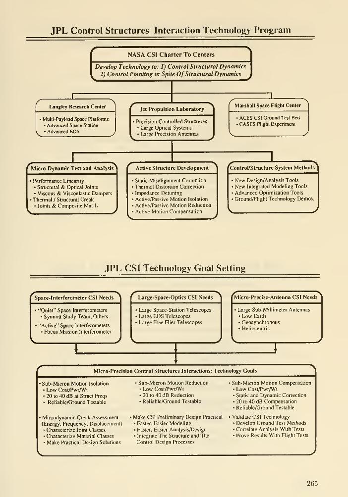
JPL Control Structures Interaction Technology Program
NASA CSI Charter To Centers
Develop Technology to: 1) Control Structural Dynamics
2) Control Pointing in Spile Of Structural Dynamics
XLangley Research Center
' Multi-Payload Space Platforms
• Advanced Space Station
• Advanced EOS
Jet Propulsion Laboratory
• Precision Controlled Structures
• Large Optical Systems
• Large Precision Antennas
Marshall Space Flight Center
ACES CSI Ground Test Bed• CASES Flight Experiment
Micro-Dynamic Test and Analysis
• Performance Linearity
• Structural & Optical Joints
• Viscous & Viscoelastic Damf)ers
• Thermal / Structural Creak
• Joints & Composite Mat'ls
Active Structure Development
• Static Misalignment Correction
• Thermal Distortion Correction
• Impedance Detuning
• Active/Passive Motion Isolation
• Active/Passive Motion Reduction
• Active Motion Compensation
Control/Structure System Methods
• New Design/Analysis Tools
• New Integrated Modeling Tools
• Advanced Optimization Tools
' Ground/Flight Technology Demos.
JPL CSI Technology Goal Setting
Space-Interferometer CSI Needs
• "Quiet" Space Interferometers
• Synnott Study Team, Others
• "Active" Space Interferometers
• Focus Mission Interferometer
Large-Space-Optics CSI Needs
' Large Space-Station Telescopes
• Large EOS Telescopes
• Large Free Flier Telescopes
Micro-Precise-Antenna CSI Needs
• Large Sub-Millimeter Antennas
• Low Earth
• Geosynchronous• Heliocentric
Micro-Precision Control Structures Interactions: Technology Goals
• Sub-Micron Motion Isolation
• Low Cosl/Pwr/Wt• 20 to 40 dB at Struct Freqs
• Reliable/Ground Testable
• Microdynamic Creak Assessment
(Energy, Frequency, Displacement)
• Characterize Joint Classes
• Characterize Material Classes
• Make Practical Design Solutions
• Sub-Micron Motion Reduction
• Low Cost/Pwr/Wt• 20 to 40 dB Reduction
• Reliable/Ground Testable
' Make CSI Preliminary Design Practical
• Faster, Easier Modeling• Faster, Easier Analysis/Design
• Integrate The Structure and The
Control Design Processes
' Sub-Micron Motion Compensation• Low Cost/PwrAVt• Static and Dynamic Correction
• 20 to 40 dB Compensation• Reliable/Ground Testable
' Validate CSI Technology• Develop Ground Test Methods• Correlate Analysis With Tests
• Prove Results With Flight Tests
265

JPL CSI Technology: Active Structure
• Active Structures Include:
• Actuators: Electromechanically Extensible Truss-Struts (and Shells)
• Integral In The Primary Structural Paths
• Small Motion Control: High BW (=1000 Hz) (nanometers-to-100 micron)
• Large Motion Control: Quasi-Static (millimeters to centimeters)
• Local Sensors: Displacement, Velocity, Acceleration, Force, Temperature, etc.
• Collocated With Each Actuator
• Local Control Loops: High Bandwidth, (Typically Analog for Speed)
• Active Control Of: Damping, Stiffness, Thermal Contraction, etc.
• Active Structures Can Provide:
• Structural Property Control (Factor-of-Ten to Factor-of-One-Hundred) Such As:
• Damping Changes to Reduce Vibration Response
• Stiffness Changes to Detune Resonant Modes• Force Isolation From Disturbances
• Active Motion Compensation
• Thermal Expansion Reduction (Factor-of-Ten to Factor-of-One-Hundred)
JPL CSI Technology: Micro-Dynamic Test & Analysis
• Micro-Dynamic (Motion Under 10 micron) Issues
• Structural Stiffness and Damping• "Micro-Behavior" Deviation From "Macro-Behavior"
• Non-Linear Continuous... Load-Stiffening, Load-Softening
• Non-Linear Discontinuous. ..Backlash, Stick-Friction
• Static Position Maintenance
• Material and Joint Micro-Creep and Hysteresis Behavior
• Bizarre Disturbance Sources
• Thermal Creak
• Micro-Creep Strain Relief "Popping"
• High Frequency Ratcheting of Load Changes
• Micro-Dynamic Assessment Approach
• Conduct Micro-Dynamic, Staticand Thermal Load/Displacement Tests On:
• Structural & Optical Materials, Joints, Dampers, and Actuators
• Identify/Develop Components Having Acceptable Micro-Dynamic Behavior
• If Necessary, Develop Analysis/Design Methods Which Work Despite Significant
Micro-Dynamic Effects
266

Control Structures Interaction: System Architecture
csi
Disturbance
Motion Isolation
Active Members
Pointing '
Line of Sight i
OnDisturbances
CSI
Motion Reduction
Active Members
CSI
Motion
Compensation
Active Members
JPL CSI Preliminary Specifications: Active Structure Driver
•Maximum Force Output: ==±100 pounds (±443 newtons)
• Force Increment Resolution: M).006 pounds (0.027 newtons)
• Maximum Stroke: »d:4 10 ' inch (±102 microns)
•Stroke looipment Resolution: «±0.24 10 ' inch (±6 nanometers)
•Open Loop Stiffness: =10^ pounds/inch (17.5 lO' newtons/meter)Mi««<. to4
•Qosed Loop Stiffness Range: (O.OlXOpen Loop) to (100)(Open Loop)
• Closed Loop Stiffness To Qe Commandable
• Open Loop Energy Dissipation: Less Than 10% of Induced Strain Energy
• Closed Loop Energy Dissipation Range: 0. 1% to 90% of Induced Strain
Energy
• Closed Loop Energy Dissipation Is Commandableruioalactrlc
• Average Power 10 watts. In Remote Electronics, 0.1 watt In Actuator
• Weight: 2 kg In Stmt. Skg In Electronics
^^yy^yl^ Bandwidth: Zero to 1000 Hz
267

VIBRATION ENVIRONMENTAND CONTROL APPROACH
1000
100
10
INDUCEDVIBRATIONS
_ Stabimy Reqt:
7.5 nanometers (0.3 mAS at 5 meters)
1 10
OPTICAL COMPENSATION
Hz
ALIGNMENT CONTROLACTIVE/PASSIVE VIBRATION DAMPING
VIBRATION ISOLATION
JPL CSI Technology: Active Structure Test Results
- GRID 41
DISTURBANCESOURCE
LOAD CEU
ACTIVE MEMBERSTRUT 1
1
ACTIVE MEMBERDIAGONAL
LOAD CELL
GRID 42
LOAD CELL
ACTIVE MEMBERSTRUT 22
Fr«« Decay
AdlvUa Cl iiBi it Loop Canlral
t 4
268

DISCUSSION
Bely: What gain in mass over conventional systems can we expect from an active structure?
Layman: In a representative calculation, about 100 times the stiffness of support structure (5 to
10 times the mass) was required to obtain as low a structural vibration response with a conventional
structure as was achievable with a controlled structure. There is no good rule ofthumb for conventional
structural equivjilents to controlled structure. It may be impractical to solve many future problems
with a conventional structure.
269
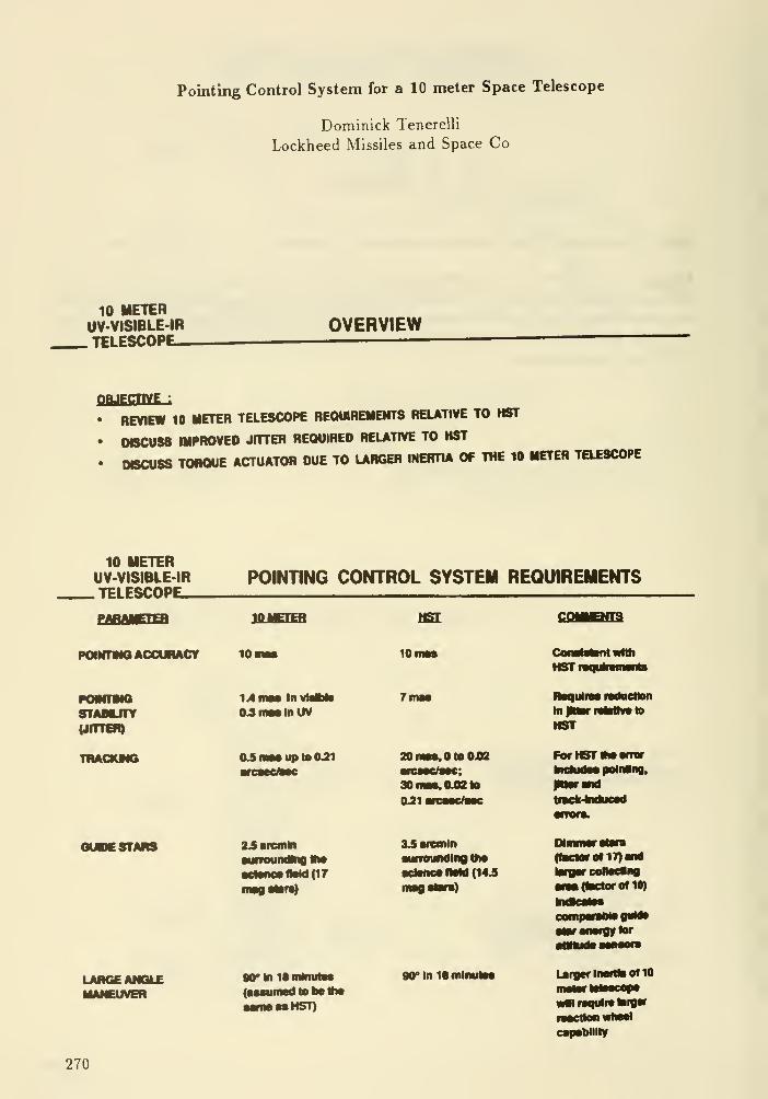
Pointing Control System for a 10 meter Space Telescope
Dominick Tenerelli
Lockheed Missiles and Space Co
10 METERUV-VISIBLE-IR.TELESCOPE-
OVERVIEW
QpjgcnvE :
• REVIEW 10 METEB TELESCOPE BEQUIBEIIEIITS RELATIVE TO HST
• OeCUSS WPROVEO JITTER REQUIRED REUTWE TO HST
• DBCUSS TOBQOE ACTUATOR DUE TO LARGER INERTIA OF THE 10 METER TELESCOPE
10 METERUV-VISIBLE-IR.TELESCOPE-
POINTING CONTROL SYSTEM REQUIREMENTS
IOMETER
PaNTMOAOCUfMCt
POMnNQsrrAaurv(JITTBI)
TRACMNG
10
1
14 RIM In
04mM In UV
OJmMiiptoO^
10
20 OtoOJ02
30niM.0Jttlo
OJIi
CoiNMBnl Willi
HSTi
RaqirirM raduetlon
In IMmtivMIw to
HST
FOrHSTMitwrarIndudM poliMInQ,
tmck-lnduMd
OUDE STARS
LARGE ANGLEMANEUVER
23nrcniln
MTfoundkiQ VwMl«nMlWd(17
Mrinltmlnum(Hsumed to be ttw
imHST)
UMcnrin•unoundlng llw
)MM (143
)
90*ln1SmlnulM
mi(factor 0117) nd
roflO)
•tBronotgytor
Larger Ineftii of 10
wMrequlrelaivw
•action wtwet
capaMllly
270

10 METERUV-VISIBLE-IR. TELESCOPE—
JITTER COMPONENTS BASED ON HST
RANDOM3ma6
GYRO NOSEPHOTON NOSE
(0->1HZ)
OVERALL JTTER7fna$
FAST SINE
4ina6
SLOW SINE
1 masEXPONENTIAL
4masSI
2ma5 (BUDGET
STRUCTURALJITTER
SOLAR ARRAY(01 -> 1 Hz)
ITmas
THERMALCONTRaOF OPTICS(0->0.1HZ)
THERMAL NOUCEDMOTION DUE TOREORENTATICNOF TELESCOPE(a-> 0.001 HZ)
TELESCOPE(20 -> 60 Hz)
37 mas
• CONSIDERATION OF A TWOLAYERCONTRa SYSTEM. IE. BODY POINTINGAUGMBOED BY MAGEMOTION COMPENSATION OMC). TO ACHIEVE 1.4 MAS M THE VSBLE ( 0.3 MAS IN THE UV ) MDICATES AHIGHBANOWDTH FINE GUIDANCE SENSOR WILL BE REQURED TO REDUCE ERRORSSMCE SOMEERROR SOURCES HAVE FREQUENCIES UP TO 60 HZ. OR MORE
• TO ACHEVE LOW PHASE ERROR IN TRACKING THE POINTING DEVIATIONS, THE IMC SENSOR MUST HAVEA BANDWDTH 5 - 10TWES HIGHER THAN THE DISTURBANCE A CONDITION HARD TO SATISFY FOR THE
17 MAG GUIDE STAR.
SUMMARY : REDUCTION OF ERROR SOURCES AND PRECISE BODY POINTNG WILL BE KEY TO ACHIEVING THE
jnTEH REQUIRaCNTS
10 METERUV-VISIBLE-IR. TELESCOPE-
TYPICAL RWA/STRUCTURAL JITTER
;s.7«n 4 l« 3.ZS* 3.12 2.0.19 A
H.7 n.7 2t.7 2(.r 24.3. 100.1
2.M2«.3
1.0. 2.11
as. n.i
-MuamocNa MC Foiczookraew
0.0 z.i J.i 10.9 I2.S IS.O
MHEEL SF-HD IHZI
».o S.Ot.N-MCMcrancE
BBjOW 10 HZWHEB. SPEED THE DOMINANT SOURCES OF DISTURBANCE ARE T»E REACTION WHEELTORQUER RIPPLE T>CflE ARE A FEW COMPONENTS OF AXIAL AND RADIAL FORCE
ABOVE 10 HZ THE RWA FORCES DCMNATE
THE FREQUENOES OF THE DISTURBANCES VARY FROM 22 T0 104 HZ. 271

10 METERwv yisiBLEiR RWA MANEUVERING FOR THE 10 METER TELESCOPE_ TELESCOPE
• NST IS PRIMARILV TORQUE LIMITED FOR MANEUVERS, NOT MOMENTUM UNITED.
< M HEO. LE. . m A GEOSYNCHRONOUS OR 100,000 KM ORBIT, THE DOMINANT
TORQUES WHX BE SOUR PRESSURE AND HEUUH BON. OFF FROM THE IR
INSTRUMENTS, BOTH OF WHICH ARE SMALL COMPARED TO THE TORQUES ON HST
IN THE LOW EARTH ORBIT.
MANEUVER TIME IN HEO IS NOT i» CRITICAL AS IT IS ON HST DUE TO THE LONGERORBIT PERIOD, AND HENCE LONGER TIME PERIOD FOR WHICH THE TARGET IS
AVAILABLE.
THE EXISTING HST REACTION WHEEL ASSEMBUES (RWAs) CAN ACHIEVE 1.1 NMTORQUE (34 % TORQUE BICREASE RELATIVE TO HST) AND >4000 RPM (33 %MOMENTUM INCREASE RELATIVE TO HST) WITH MMOR ELECTRONICMODIFICATIONS.
• WITH AN INCREASE IN RWA TORQUE AND SPEED, THE 10 METER TELESCOPE CANACHIEVE ESSENTIALLY HST MANEUVER PERFORMANCE WITH VEHICLE INERTIAS
OF 200,000 KG-M^Z. (MAXMUH HST INERTIA IS APPROXMATELY 00,000 KG-M«2).
SUMMARY : EMSTING RWAs CAN BE MODIFIED FOR THE LARGER 10 METER TELESCOPEINERTIA.
RWAs V5 CMGs
Each actuator has Its assets. The CMG can provide high torque, high momentum storage capability
and. the force dIstuiiMmces tend to be at flxed freoucnclcB. The high torque capability of the CMO Is
not needed for the 10 meter telescope. The fibced ncquendes of the CMG rotor forces and torquesmake It attractive when viewed relative to the fact that the changing RWA irtied speed causes theRWA to 'sweep' through the telescope structural modes. For example. If the HST bearing were usedin a CMG which had a rotor frequency of 100 Hz (6000 RPM). the bearing forces would have a smaOcomponent due to the retainer at 34 Hz. The other dominant forces and moments would be at 100Hz. 282 Hz. 516 Hz. 560 Hz. ct al. frequencies which could be effectWdy reduced by an Isolatar. If
required. Also, the CMG could Incorporate a capability to reset Its spin speed over a small range.
e.g. . ± 5% about the 100 Hz nominal speed to avoid troublesome structural modes. Mfwt CMGdevelopment to date has been for large devices. Relatively few small devices have been built (oneexample Is the astronaut manned maneuvering unit), and none have not been concerned with ultra-
low force, moment and torque ripple noise in the development of these devices.
The HST RWA can meet the maneuvering requirements and has been extensively characterizedrelative to its noise producing error sources.
Using 'today's persecttve" on the 10 meter telescope, which is many years from actual hardwareImplementation. It is better to spend any available technology funds to pursue a low noise RWA atthis time.
272
IOMETERUV-VISIBLE-IR NUMMARY
. TELESCOPEbUMMAHY
JITTER PRESENTS THE TECHNOLOGY CHALLENGE. IT S EXPECTED THAT THE 1.4 MAS (20% OF HST)JITTER REQUIREMENT CAN BE MET WITH DESIGNS USMG AVAILABLE ATTTTUDE CONTROLACTUATORS EMPLOYED M PROVEN HST CONTROL LAWS AND USER INTERFACES. THE 0.3 MAS ( 4%OF HST) JITTER REQUIREMENT FOR UV WLL REQUIRE ADDITIONAL DEVELOPMBfT OF LOW NOISEGYROS, RWAs AND "QUIET STRUCTURES.
PRECISION BODY POMUNG COUPLED WTTH REDUCTIONS IN D6TURBANCES WILL BE THE PRMECANDIDATE TO MEET THE 10 METER JITTER REQUREMENTS DUE TO THE DIFFICULTY M OBTAIIMG ASUITABLE MC SENSOR
USE OF IMC WILL REQUIRE DEVELOPMENT OF A HIGH BANDWIDTH SENSOR. THE STAR ENERGYAVAILABLE AT 17 MAG DOES NOT APPEAR TO SUPPORT A HKSH BANDWDTH SENSOR. BRIGHTERGUIDE STARS ARE REQUIRED, IMPLYING A LARGER FGS ACQUISITION AREA.
RWAs ARE AVAILABLE TO MEET THE 10 METER MANEUVER REQUIREMENTS. TORQUER RIPPLE ANDFORCE DISTURBANCE REDUCTIONS ARE REQUWEO TO MEET THE JITTER REQUIREMENT.
CANDIDATE TECHNOLOGY DEVELOPMBTTS
FGS WITH LARGE HELD OF VIEW AND POTENTIAL MC CAPABILITY
RWA FORCE. MOMENT AND TORQUER RIPPLE REDUCTION
GYRO NOISE REDUCTION, BOTH SENSOR AND ELECTRONICS
"QUCr STRUCTURES WITH LOW MODAL COEFFICIENTS AN0M3R HIGH DAMPING
RIGOROUS CONTROL OF DISTURBANCES FROM Sis AS WELL AS VEHICLE EQU»>IKNT, E.G.
.
TAPE RECORDERS
USER COMMAND INTERFACE BETWEEN GROUND SEGMENTS AND WflH THE VEHICLE
DISCUSSION
Layman: Are the reaction wheels larger than for HST?
Tenerelli : Yes, about 30% larger.
Unidentified : You noted that some people at LMSC feel that you should use CMGs, Controlled
Moment Gyros, instead of reaction wheels. Why use reaction wheels?
Tenerelli : Because of problems with CMGs on Skylab there is a bias against CMGs and towards
reaction wheels amongst some folks. In our organisation there is a strong element who feel that CMGsshould be the momentum compensation device that is used. But we can make either work.
Stockman : What was the structure you assumed for your analysis for a 10 meter telescope?
Tenerelli : We assumed that we would have a metering structure and a focal plane structure that
would have at least the stiffness of HST.
273

Moving Target Tracking for a Next Generation Space Telescope
David R. Skillman
HST Project Office, Goddard Space Flight Center
Abstract
The Hubble Space Telescope required a complex method for tracking targets in motion in the solar
system, due mostly to atmospheric drag effects. A NGST in high earth orbit, or on the Moon, would not
suffer these drag effects, thus mitigating the tracking problem. Many of the HST problems arise from
the 'open-loop' nature of the tracking method. An NGST would be better off if it could use 'closed-loop'
tracking of all targets, both fixed and moving. A method to accomplish this is proposed. Methods
to reduce the jitter and lower the ambient temperature of the optics via a tethered optical system are
proposed.
1. Introduction
The Hubble Space Telescope required a complex method for tracking targets in motion
in the solar system. Most of that complexity is driven by the low orbit of HST and the
attendant atmospheric drag effects. Target tracking must be 'open-loop' on HST since
vehicle tracking is done on the guide stars, not on the target. This puts a burden on the
predictive capabilities of the ground system.
The track of a moving target is usually known in terms of celestial coordinates. The
ability of a spacecraft to follow this path in its own coordinate system is limited by the
quality of the registration between the two.
Jitter is a concern for both fixed and moving targets. The jitter in HST comes from
those parts of the spacecraft that move during an observation. If the jitter-inducing
components could be isolated from the optical system, a much better performance could
be obtained.
2. The effects of atmospheric drag on moving targets
In order to understand why atmospheric drag is a problem, the following chain of
reasoning is presented:
a) In order to plan the observing schedule efficiently, one wants to have the schedules
planned well in advance.
b) Targets in the solar system have a substantial parallax motion due to the orbiting
motion of the spacecraft. This spacecraft- induced parallax motion of the target can
only be tracked if the position and velocity of the spacecraft are well known in advance.
c) The position of the spacecraft rapidly becomes unpredictable if atmospheric drag is
significant. Variations in solar activity can dramatically affect the drag. For HST the
position uncertainty can grow to the order of a 1000 km in a month. At Jupiter this
would correspond to pointing errors of hundreds of milliarcseconds.
These three considerations show that it is impossible to produce a tracking profile
(spacecraft attitude as a function in time in the control system coordinates of the space-
craft) that will remain accurate for execution a month or more in the future.
This problem was solved on HST by generating all tracking paths in geocentric coor-
dinates and then having the HST flight computer perform the coordinate transformation
from geocentric to spacecraft centered coordinates. The orbit ephemeris of the HST in
274

the flight computer is corrected every few days (and can be updated within 12 hours if
needed) to remove the drag error.
A NGST in high earth orbit, or on the Moon, would not suffer these drag effects,
thus mitigating the tracking problem. Thus, for the low drag locations the generation of
tracking paths, even in spacecraft coordinates and for times well in advance of observation,
is simplified considerably and are not a significant design driver either in the spacecraft
or ground system area. A low earth orbit for a NGST would be susceptible to the same
problems faced by HST and would need similar solutions.
3. The roll error problem
The track of a moving target is most naturally known in terms of celestial coordinates.
Right ascension and declination coordinates are not the optimal representation since the
distance to the target is also needed to allow for parallax variations. Typically it is best
to use an inertial X,Y,Z system since most ground system and flight system elements use
the GEI (geocentric earth inertial) coordinate system. The path is then described as the
time evolution of the three components of the position vector.The ability of a spacecraft
to follow this path in its own coordinate system is limited by the quality of the registration
between the two.
The roll error between celestial and spacecraft systems is the hardest to control. For
HST this error will be of the order of 30 arcseconds and is set by the resolution of the
fixed head star trackers and the knowledge of their alignment to the spacecraft. This
roll error manifests itself as a pointing error which increases proportionally to the track
length. This error is of the order of 30 milliarcseconds at the end of a three arcminute
length track.
For a NGST with a pointing stability requirement below a milliarcsecond, roll refer-
ence star positions would have to be known to an arcsecond or better and the star tracker
would have to have a resolution of better than an arcsecond. Astrometric stars would
probably be required for these roll control stars (i.e. Hipparcos stars). The nominal three
arc minute track length used for HST is predicated on the width of the FGS pickoff mir-
rors. A telescope that is responding to true science requirements may want track lengths
much longer. (Halley at closest approach was moving 3 arc minutes in 15 minutes of
time.) Such longer track lengths make the roll knowledge even more crucial for moving
targets.
Again, this roll problem is due in part to the inability to 'closed-loop' track on the
target. If the moving target itself is used to generate an error signal, this roll issue
disappears.
Traditionally a dichroic beam splitter or pellicle is inserted near the focus to divert
light into a guiding device. An alternate way to be able to view a target while also
performing a science observation would be to intercept some of the light directly at the
prime focus of the primary while allowing the bulk of the light to trace a nominal path
through the rest of the telescope optics. A camera at the prime focus could then generate
the necessary error signals for the pointing control system (Figure 1).
The advantages of this approach would be that the amount of intercepted light could
be controlled by geometry rather than by index of refraction changes or by partial reflec-
tions. No pickoff mirrors need to be devoted to the guidance system. The roll axis would
be controlled by the fixed head star trackers, thus only one guidance camera is needed.
275
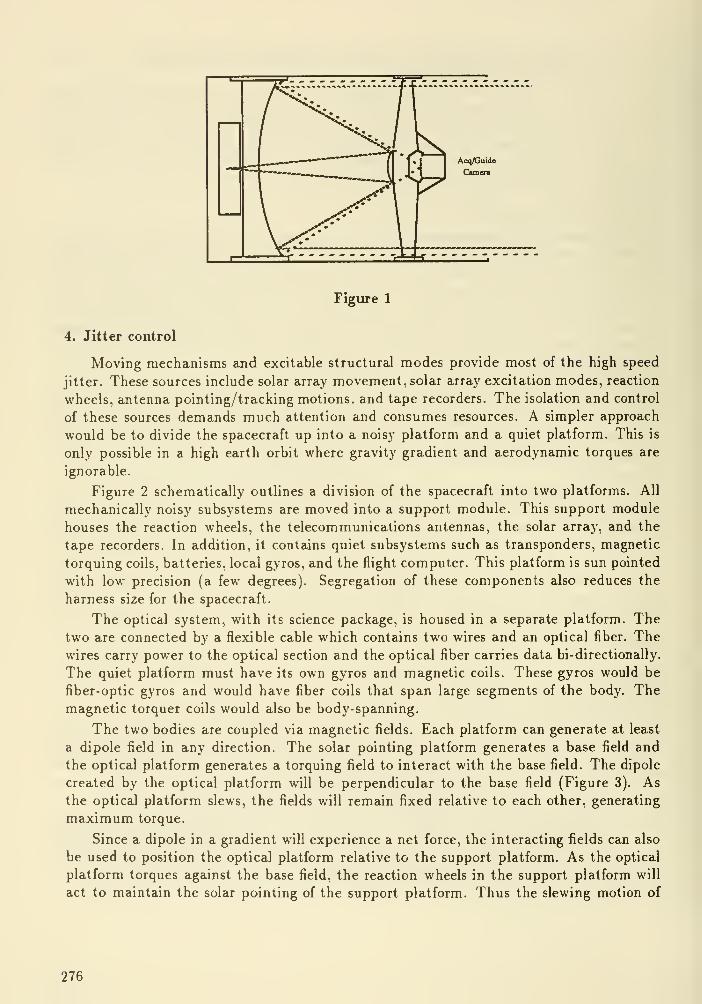
Figure 1
4. Jitter control
Moving mechanisms and excitable structural modes provide most of the high speed
jitter. These sources include solar array movement, solar arraj' excitation modes, reaction
wheels, antenna pointing/tracking motions, and tape recorders. The isolation and control
of these sources demands much attention and consumes resources. A simpler approach
would be to divide the spacecraft up into a noisy platform and a quiet platform. This is
only possible in a high earth orbit where gravity gradient and aerodynamic torques are
ignorable.
Figure 2 schematically outlines a division of the spacecraft into two platforms. All
mechanically noisy subsystems are moved into a support module. This support module
houses the reaction wheels, the telecommunications antennas, the solar array, and the
tape recorders. In addition, it contains quiet subsystems such as transponders, magnetic
torquing coils, batteries, local gyros, and the flight computer. This platform is sun pointed
with low precision (a few degrees). Segregation of these components also reduces the
harness size for the spacecraft.
The optical system, with its science package, is housed in a separate platform. Thetwo are connected by a flexible cable which contains two wires and an optical fiber. Thewires carry power to the optical section and the optical fiber carries data bi-directionally.
The quiet platform must have its own gyros and magnetic coils. These gyros would be
fiber-optic gyros and would have fiber coils that span large segments of the body. Themagnetic torquer coils would also be body-spanning.
The two bodies are coupled via magnetic fields. Each platform can generate at least
a dipole field in any direction. The solar pointing platform generates a base field and
the optical platform generates a torquing field to interact with the base field. The dipole
created by the optical platform will be perpendicular to the base field (Figure 3). Asthe optical platform slews, the fields will remain fixed relative to each other, generating
maximum torque.
Since a dipole in a gradient will experience a net force, the interacting fields can also
be used to position the optical platform relative to the support platform. As the optical
platform torques against the base field, the reaction wheels in the support platform will
act to maintain the solar pointing of the support platform. Thus the slewing motion of
276

Solar
array
and
Sun
shield
SUNLINE
Figure 2
Figure 3
277

the optical platform will be reflected in the increased reaction wheel speed of the support
platform.
The large circular solar array/solar shield structure is designed to cast a shadow region
in which the optical platform can operate. This provides a number of benefits. The first
benefit is that the passive temperature of the telescope can be lowered considerably. This
will lend itself to achieving lower optical surface temperatures for infrared performance
and for lower ambient detector temperatures. Power from the tether will supply heat to
those instrument components that prefer higher temperatures. The second benefit is that
the telescope line of sight can come closer to the sun than 90 degrees. This allows access
to more of the sky and allows observations over longer time windows. Inner solar system
objects such as Venus and comets can also be followed closer to the Sun.
5. Conclusion
The primary conclusions of this paper are that closed-loop tracking of both fixed and
moving targets is highly advantageous, that fixed head star trackers of high resolution are
needed for roll control, that an alternate method exists for imaging the target on both the
science instrument and the guidance camera, and that a dual platform offer substantial
vibration isolation.
DISCUSSION
mingworth: David, you made an interesting point about the difficulty of doing planetary observations
from the lunar poles. However, I do not think that we are likely to face that problem. As good as
these sites would be for tistronomical telescopes, I cannot see us getting access to these sites in our
lifetimes, especially for the two telescopes needed for full sky coverage.
278
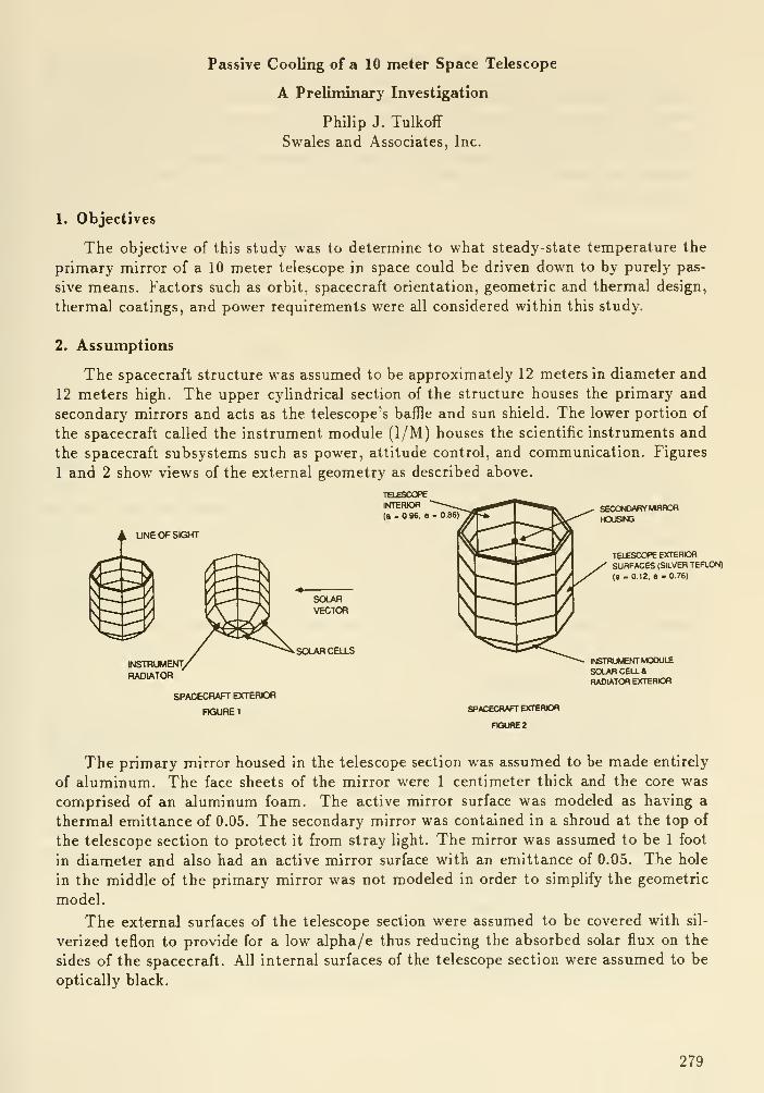
Passive Cooling of a 10 meter Space Telescope
A Preliminary Investigation
Philip J. Tulkoff
Swales and Associates, Inc.
1. Objectives
The objective of this study was to determine to what steady-state temperature the
primary mirror of a 10 meter telescope in space could be driven down to by purely pas-
sive means. Factors such as orbit, spacecraft orientation, geometric and thermal design,
thermal coatings, and power requirements were all considered within this study.
2. Assumptions
The spacecraft structure was assumed to be approximately 12 meters in diameter and
12 meters high. The upper cylindrical section of the structure houses the primary and
secondary mirrors and acts as the telescope's baffle and sun shield. The lower portion of
the spacecraft called the instrument module (I/M) houses the scientific instruments and
the spacecraft subsystems such as power, attitude control, and communication. Figures
1 and 2 show views of the external geometry as described above.
UNE OF SIGHT
SOLAR CELLS
SECONDARY MRFORHOUSMj
TELESCOPE EXTEROHSURFACES (SILVER TEFLON)
(a - 0.12. e - 0.76)
INSTRUMENfT MODULESOLAR CELL*RADIATOR EXTEROfl
SPACECRAFT EXTERIOR
FIGURE 1SPACeCRAFT EXTERIOn
FIQUnEZ
The primary mirror housed in the telescope section was assumed to be made entirely
of aluminum. The face sheets of the mirror were 1 centimeter thick and the core was
comprised of an aluminum foam. The active mirror surface was modeled as having a
thermal emittance of 0.05. The secondary mirror was contained in a shroud at the top of
the telescope section to protect it from stray light. The mirror was assumed to be 1 foot
in diameter and also had an active mirror surface with an emittance of 0.05. The hole
in the middle of the primary mirror was not modeled in order to simplify the geometric
model.
The external surfaces of the telescope section were assumed to be covered with sil-
verized teflon to provide for a low alpha/e thus reducing the absorbed solar flux on the
sides of the spacecraft. All internal surfaces of the telescope section were assumed to be
optically black.
279
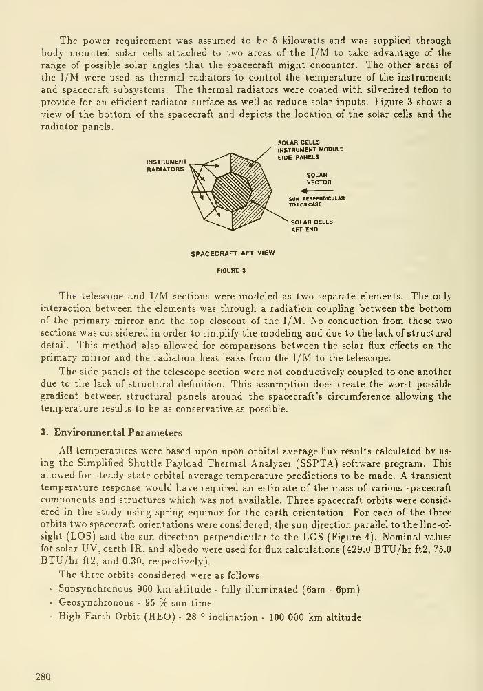
The power requirement was assumed to be 5 kilowatts and was supplied through
bod}' mounted solar cells attached to two areas of the I/M to take advantage of the
range of possible solar angles that the spacecraft might encounter. The other areas of
the 1/M were used as thermal radiators to control the temperature of the instruments
and spacecraft subsystems. The thermal radiators were coated with silverized teflon to
provide for an efficient radiator surface as well as reduce solar inputs. Figure 3 shows a
view of the bottom of the spacecraft and depicts the location of the solar cells and the
radiator panels.
SOLAR CELLSINSTRUMENT MODULE
^ v,,r^^ ^ SIDE PANELSINSTRUMENT ^ kxx/7>^x
RADIATORS _SOLARVECTOR
<SUN PERPENDICULARTO LOS CASE
SOLAR CELLSAFT END
SPACECRAFT AFT VIEW
FIGURE 3
The telescope and I/M sections were modeled as two separate elements. The only
interaction between the elements was through a radiation couphng between the bottom
of the primary mirror and the top closeout of the I/M. No conduction from these two
sections was considered in order to simplify the modeling and due to the lack of structural
detail. This method also allowed for comparisons between the solar flux effects on the
primary mirror and the radiation heat leaks from the I/M to the telescope.
The side panels of the telescope section were not conductively coupled to one another
due to the lack of structural definition. This assumption does create the worst possible
gradient between structural panels around the spacecraft's circumference allowing the
temperature results to be as conservative as possible.
3. Environmental Parameters
All temperatures were based upon upon orbital average flux results calculated by us-
ing the Simplified Shuttle Payload Thermal Analyzer (SSPTA) software program. This
allowed for steady state orbital average temperature predictions to be made. A transient
temperature response would have required an estimate of the mass of various spacecraft
components and structures which was not available. Three spacecraft orbits were consid-
ered in the study using spring equinox for the earth orientation. For each of the three
orbits two spacecraft orientations were considered, the sun direction parallel to the line-of-
sight (LOS) and the sun direction perpendicular to the LOS (Figure 4). Nominal values
for solar UV, earth IR, and albedo were used for flux calculations (429.0 BTU/hr ft2, 75.0
BTU/hr ft2, and 0.30, respectively).
The three orbits considered were as follows:
- Sunsynchronous 960 km altitude - fully illuminated (6am - 6pm)- Geosynchronous - 95 % sun time
- High Earth Orbit (HEO) - 28 ° inclination - 100 000 km altitude
280

4. Thermal Model
The spacecraft was modeled with 156 active surfaces which were combined to form 102
nodes for temperature calculations. Multi- layered insulation (MLI) was used in several
areas on the spacecraft to minimize heat gain from solar inputs and warmer surrounding
structures. The bottom of the primary mirror was assumed to be covered with MLI to
prevent interactions with the warmer I/M located below it. The sides of the telescope
were covered with MLI to prevent excessive heat inputs to the mirrors and to reduce the
circumferential gradient around the structure.
Four different modeling assumptions were made for each orbit/ spacecraft orientation
combination. The assumptions were as follows:
Case A: No I/M coupling to the telescope allowing for only environmental heat
flux inputs to efl^ect the mirror temperature. No MLI on the anti-sun side
of the telescope to allow for maximum heat dissipation to space.
Case B: No I/M coupling to the telescope. MLI around the entire telescope cir-
cumference.
Case C: No conduction coupling from the I/M to the telescope. Assumed that
the I/M portion of the spacecraft operated at 20F and that a radiation
coupling from the top of the I/M to the bottom of the telescope section
existed. MLI around the entire telescope circumference.
Case D: No conduction coupling from the I/M to the telescope. Assumed that
the I/M portion of the spacecraft operated at 20F and that a radiation
coupling from the top of the I/M to the bottom of the telescope section
existed.No MLI on the anti- sun side of the telescope.
5. Results
A series of twenty-four cases were run as a result of the three orbits, two spacecraft
orientations, and the four modeling assumptions. The results are summarized in Table 1.
All cases that assumed no I/M coupling result in primary mirror temperatures that
were determined strictly by environmental flux leakage through the MLI and in some cases
by the combined effect of earth IR or albedo which enters the telescope aperture. The
sunsynchronous orbit was warmer than all other cases considered due to its low altitude
which caused higher fluxes incident on the telescope external surfaces. On the sun parallel
to the LOS orientation and sunsynchronous orbit enough flux gets into the telescope to
cause the primary mirror temperature to rise almost 45K above the sun perpendicular
case.
The geosynchronous orbit showed similar temperatures for the parallel and the per-
pendicular to LOS cases. A careful examination of the absorbed fluxes showed that the
primary mirror temperature in the sun perpendicular to the LOS case was determined by
the solar and earth IR fluxes incident on the exterior of the telescope. In the sun parallel
to the LOS case, there is no solar flux and less earth IR on the telescope exterior than in
the previously mentioned case. The temperature of these two cases are extremely similar
because a total of 2.8 watts of earth IR flux are absorbed directly by the primary mirror
in the sun parallel case and no flux is absorbed directly by the mirror in the other case.
This is because in the sun parallel to the LOS case the telescope is pointing directly at
the earth as it passes the 12:00 position in the orbit.
281

Table 1,
Case Primary mirror
temp. (°K)
Sunsynchronous Orbit - Sun perpendicular to LOS
A. No I/M coupling, no MLI anti-sun side 143.
B. No I/M coupling, full MLI 109.
C. 20F I/M coupling, full MLI 120,
D. 20F I/M coupling, no MLI anti-sun side 146.
Sunsynchronous Orbit - Sun pztrallel to LOS
A. No I/M coupling, no MLI anti-sun side 188.
B. No I/M coupling, full MLI 159.
C. 20F I/M coupling, full MLI 163.
D. 20F I/M coupling, no MLI anti-sun side 190.
Geosynchronous Orbit - Sun perpendicular to LOS
A. No I/M coupling, no MLI anti-sun side 91.
B. No I/M coupling, full MLI 97.
C. 20F I/M coupling, full MLI 106.
D. 20F I/M coupling, no MLI anti-sun side 96.
Geosynchronous Orbit - Sun paraUel to LOS
A. No I/M coupling, no MLI anti-sun side 93.
B. No I/M coupling, full MLI 96.
C. 20F I/M coupling, full MLI 105.
D. 20F I/M coupling, no MLI anti-sun side 98.
High-earth Orbit - Sun perpendicular to LOS
A. No I/M coupling, no MLI anti-sun side 85.
B. No I/M coupling, full MLI 94.
C. 20F I/M coupling, full MLI 104.
D. 20F I/M coupling, no MLI anti-sun side 90.
High-earth Orbit - Sun parallel to LOS
A. No I/M coupling, no MLI anti-sun side N/AB. No I/M coupling, full MLI N/AC. 20F I/M coupling, full MLI 78.
D. 20F I/M coupling, no MLI anti-sun side 66.
R. 20C I/M coupling, no MLI anti-sun side 73.
282
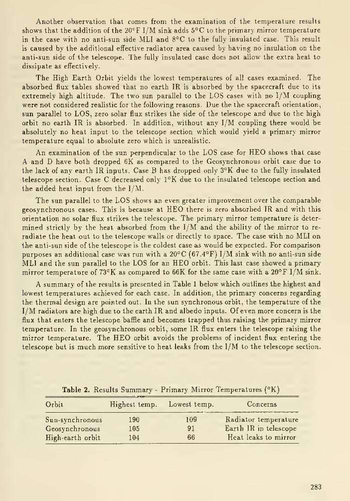
Another observation that comes from the examination of the temperature results
shows that the addition of the 20°F I/M sink adds 5°C to the primary mirror temperature
in the case with no anti-sun side MLI and 8°C to the fully insulated case. This result
is caused by the additional effective radiator area caused by having no insulation on the
anti-sun side of the telescope. The fully insulated case does not allow the extra heat to
dissipate as effectively.
The High Earth Orbit yields the lowest temperatures of all cases examined. Theabsorbed flux tables showed that no earth IR is absorbed by the spacecraft due to its
extremely high altitude. The two sun parallel to the LOS cases with no I/M coupling
were not considered realistic for the following reasons. Due the the spacecraft orientation,
sun parallel to LOS, zero solar flux strikes the side of the telescope and due to the high
orbit no earth IR is absorbed. In addition, without any I/M coupling there would be
absolutely no heat input to the telescope section which would yield a primary mirror
temperature equal to absolute zero which is unrealistic.
An examination of the sun perpendicular to the LOS case for HEO shows that case
A and D have both dropped 6K as compared to the Geosynchronous orbit case due to
the lack of any earth IR inputs. Case B has dropped only 3°K due to the fully insulated
telescope section. Case C decreased only 1°K due to the insulated telescope section and
the added heat input from the I/M.
The sun parallel to the LOS shows an even greater improvement over the comparable
geosynchronous cases. This is because at HEO there is zero absorbed IR and with this
orientation no solar flux strikes the telescope. The primary mirror temperature is deter-
mined strictly by the heat absorbed from the I/M and the ability of the mirror to re-
radiate the heat out to the telescope walls or directly to space. The case with no MLI on
the anti-sun side of the telescope is the coldest case as would be expected. For comparison
purposes an additional case was run with a 20°C (67.4°F) I/M sink with no anti-sun side
MLI and the sun parallel to the LOS for an HEO orbit. This last case showed a primary
mirror temperature of 73°K as compared to 66K for the same case with a 20°F I/M sink.
A summary of the results is presented in Table 1 below which outlines the highest and
lowest temperatures achieved for each case. In addition, the primary concerns regarding
the thermal design are pointed out. In the sun synchronous orbit, the temperature of the
I/M radiators are high due to the earth IR and albedo inputs. Of even more concern is the
flux that enters the telescope baffle and becomes trapped thus raising the primary mirror
temperature. In the geosynchronous orbit, some IR flux enters the telescope raising the
mirror temperature. The HEO orbit avoids the problems of incident flux entering the
telescope but is much more sensitive to heat leaks from the I/M to the telescope section.
Table 2. Results Summary -
6. Conclusions
This preliminary investigation indicates that a mirror temperature in the 70 to 100°K
range appears attainable through purely passive cooling. Orbit selection is a major factor.
If a temperature approaching 70° K is desirable for scientific reasons, low earth orbits which
are strongly affected by earth radiation must be avoided and a geosynchronous or high
earth orbit is to be preferred. An additional advantage of the high earth orbit is that the
earth flux input on radiators is so negligible that the constraint on spacecraft orientation
disappears.
This study also indicates, however, that the mirror temperature is fairly sensitive to
heat leaks from the spacecraft power dissipating components. The Instrument Module
should be designed to run as cold as possible, and extreme care should be exercised in
the mechanical/thermal design in order to minimize heat leaks.
An attempt should be made to balance the heal input to the mirror resulting from
external fluxes and internal heat dissipating components regardless of spacecraft orien-
tation. This would eliminate primary mirror temperature drifts as the spacecraft moves
from one target to the next.
DISCUSSION
Bender : Can you keep the absoibtivity as low as 0.12 ovet 15 years?
Tnlkoff! This study did not address the questions concerning coatings in any great depth. It is
doubtful that the coatings absorbtivity would remain as low as 0.12 over 15 years which must be taken
into account when a more comprehensive thermal design is done. The question of thermal coating
stability is currently being addressed for the Polar Orbiting Platform which is being designed at the
Goddard Space Flight Center. Another possible source of information will be the examination of the
coating on the LDEF experiment which is due to be retrieved by the Shuttle early in 1990.
Schember : Can your discuss the specifics of your solar panel modelling, especially optical proper-
ties, W/m' at the beginning and end of life, and efficiencies? Also, what is the average solar panel
temperature and the heat leak from the solar panel to the instruments?
TnlkofE A detailed look at the solar panel was not conducted in this study since they would have
only a secondary effect on the primary mirror temperature. The solar panels would primarly affect the
I/M temperature. Optical properties used in the study were q=0.82 and e=0.78 which are nominal
properties. A more comprehensive study would include BOL and EOL properties in any analyses. The
solar cell efficiency was assumed to be approximately 10% and the total area available for mounting
solar ceUs was 775 ft'. The incident solar flux was assumed to be 420 BTU/hr ft'. The structural
design of the I/M can be used to optimize the external configuration of the solar cells. The exact angle
of the I/M side (the truncated cone shape) can be used to best place and orient the solar cells. In the
sun perpendicular to the LOS case the output of the solar panels at 10% efficiency was approximately
2600 Watts at temperatures from 17 to 88C. However, this was below the desired 5 kW. In the case
where the sun vector is parallel to the LOS, the cells produced 5950 W with cell temperatures ranging
fcom 88 to 123 C.
284
CRYOGENICS FOR SPACE OBSERVATORIES:TECHNOLOGY, REQUIREMENTS, ISSUES
Helene Schember, Ph.D.
Jet Propulsion LaboratoryCalifornia Institute of Technology
Pasadena, CA 91109
Summary
The ability to provide cooling at cryogenic temperatures is a criticalenabling technology for many of the next generation of space-based observa-tories and instruments. This report discusses the state of cryogenicstechnology and identifies and categorizes the various methods of cooling.
Nomenclature and Acronyms
ADM Adiabatic DemagnetizationARC Ames Research CenterAXAF Advanced X-Ray Astronomical FacilityCOBE Cosmic Background ExplorerCOP Coefficient of PerformanceCRAF Comet Rendezvous and Asteroid FlybyEOS Earth Observing SystemGRO Gamma Ray ObservatoryGRS Gamma Ray SpectrometerGSFC Goddard Space Flight CenterHST Hubble Space TelescopeJ-T Joule ThomsonJPL Jet Propulsion LaboratoryLDR Large Deployable ReflectorLeRC Lewis Research CenterLO Lunar ObserverMO Mars ObserverMSEC Marshall Space Flight CenterSFHe Superfluid HeliumSFU Space Flyer UnitSHOOT Superfluid Helium On-Orbit TransferSIRTF Space Infrared Telescope FacilitySTS Space Transportation SystemTEC Thermoelectric CoolerVM VuilleumierWFPC Wide Field Planetary Camera
285
Background; Spacecraft Cryogenics Experience
The planning, analysis, design and testing of spacecraft cryogenic systemsfall within the charter of spacecraft thermal control engineers. The range oftemperatures included in the cryogenics regime is somewhat flexible, sometimesconsidered to begin as high as 200 Kelvin, but usually taken to be 150 K and
below. A number of spacecraft and instruments have operational temperaturesin the cryogenic range. Table 1 lists a sampling of spacecraft and
instruments requiring cooling to cryogenic temperatures. A number of projectsare presently under active study, design, test and/or analysis in thecryogenics area, including: Mars Observer, Lunar Observer, SIRTF, EOS, LOR,
AXAF, EOS and others. In addition, a great variety of research and
development of enabling technology in cryogenics is ongoing at NASA, includingwork on transfer of superfluid Helium (GSFC), dilution refrigeration (GSFC,
ARC, JPL), cryogenic propel 1 ant transfer (LeRC),*pulse tube refrigerators(ARC), adaptation of mechanical refrigeration to instruments (JPL), sorptionrefrigeration (JPL), magnetic refrigeration (GSFC, JPL, ARC), cryogenic heatpipes (GSFC) and long lifetime cryogenic dewars (ARC, JPL, MSEC).
Cryogenics Technologies
I. Overview
The technology used to provide cooling at cryogenic temperatures may be
divided into four fairly distinct categories. These cooler categories are:
thermoelectric, radiative, open cycle, and closed cycle refrigeration. As a
generality, the categories are listed in order of decreasing state of maturity(or flight readiness) and, perhaps not coincidentally, in order of decreasingminimum achievable temperature. There are, naturally, some exceptions to thisrule of thumb.
It is important to recognize that thermal control at cold temperaturesrequires attention to both the temperature and the heat load (or capacity) at
that temperature. These two critical pieces of information along with theorbit and spacecraft attitude lay the groundwork for the selection of the bestmethod for cooling a particular device. One Watt of cooling at 20 K is muchharder to achieve than one Watt at 200 K. Coolers also require greater inputpower to produce the same cooling capacity at lower temperature. Othertechnical or systems considerations, such as allowable temperature cycling,instrument duty cycles, sensitivity to vibration, cooldown time, contaminationenvironment and lifetime (operating and shelf), play a role in coolerselection. The heat load on a cooler is considered to be made up of threeparts shown schematically in Figure 1. The first part, usually referred to
simply as the "heat load from the detector" (or sometimes the instrument heatload) is the heat which enters through the device and which must be removed to
maintain temperature. This heat load comes from the actual signal to thedevice, the device dissipation and any parasitic heat load carried through the
detector. The second component of total heat load is called the parasitic heatload or the parasitics, and is the radiative and conductive heat leak from the
warm environment (i.e., spacecraft) around the device. The final contributionto the total heat load is the environmental heat load, which consists of the
heat load from the Sun, and, if applicable, from planetary thermal emissionand solar reflection. Radiative heat loads from distant parts of the
286

spacecraft may be included in this category.
II. Thermoelectric Coolers
Thermoelectric coolers or TECs are small, lightweight and completelyvibrationless solid-state devices which provide refrigeration by using thePeltier effect (the reverse effect is called Seebeck) . These devices requirea source of electrical power to provide cooling. They are sometimes describedas reverse or powered thermocouples, because an electric current produces a
heat flow from the cold face to the hot face of the TEC. The current statusof these devices is mature, in that they have a long history of successfulapplication. At the present time, there are no significant developmentsunderway in TECs, other than periodic improvements in materials.
TECs are sometimes not considered to be part of the cryogenics toolbox,because they are limited to the very high end of the temperature region. Theyoperate most efficiently at temperatures above 200 K, and possibly as low as170 K. Below this temperature the efficiency, even for an optimized, stageddevice drops so low that no heat load can be supported at the cold face. TECsare generally cascaded: Marlow Industries makes a popular 6-stage device forcooling to temperatures below 200 K. In staging, the hot face of the lowerstage is in close thermal contact with the cold face of the upper stage, andso on. This makes it possible for the TEC to provide a greater temperaturedifferential from the hot side to the cold side. It must be noted that thehot face of the TEC will be fairly close to the cold face and provision mustbe made to conduct or radiate the heat away from this face. The heat at thefinal hot face may be a large quantity and is equal to the heat load at thecold face divided by the overall TEC efficiency.
Past experience with TECs dictates close attention to thermal expansion andinterfacing of the device. The TECs on the HST Wide Field Planetary Camera,carrying 60 mW at 178 K, had specially designed flexible silver straps toaccommodate movement during thermal cycling. Petri ck (1987) has described theselection and interfacing of TECs to detectors.
III. Radiative Coolers
Radiators or radiative coolers are completely passive and vibrationless. Heatfrom a source is passed to the radiator which in turn radiates to space. Highemissivity surfaces (« > 0.94) are generally required on cryogenic radiators,in order to bring them to very low temperatures. Depending on the heat loadand environment, passive radiators can reach temperatures as low as 75 K in
practice. Missions to outer planets or small cold bodies where theenvironmental heat loads are very low can support even lower temperatures.
Although radiator technology is quite mature, there are developmental taskscurrently underway. Because a radiator is so sensitive to its environment,varying mission requirements and scenarios require individual design andanalysis. Sun-synchronous orbits are preferred, in general, although they arenot always possible, as in the case of lunar orbit. The heat loading from theenvironment must be minimized along with that due to parasitics. A number ofvery clever and imaginative radiator designs have emerged in the last 10 years
287

which successfully reduce the parasitic and environmental loading, allowing
lower temperatures and higher capacities. These designs make use of multi-
staging, special low conductivity supports and highly specular surfaces to
reduce the conductive and radiative loads on the coldest stage due to
parasitic heat leaks and environment. Specular surfaces are extremely
reflective and are usually made from highly polished metal for which reflects
incoming thermal radiation at same angle as the angle of incidence. (Non-
specular surfaces exhibit diffuse reflection in which incoming rays of thermal
radiation are reflected hemispherically following a cosine law.) Specularsurfaces permit the designer to strictly limit the environmental heat loads
reaching the highly emissive (and thus highly absorptive) cold radiatorsurface. Furthermore, specular surfaces allow radiative parasitic heat leaks
to be directed away from the radiator, as best exemplified by the V-grooveradiator concept. The drawback is that these surfaces must be kept very clean-- contamination which diminishes the reflectivity or specularity could be
disastrous.
Since the capacity of the radiator is directly proportional to its area, and
proportional to the difference between the fourth powers of the radiator and
the surrounding cold sink temperatures, cryogenic radiators can be quite bulkyand heavy. The placement of the radiator can severely limit the allowablespacecraft attitude. These issues may mean that although a radiator may be a
possible solution, it may not be a practical one.
IV. Open Cycle Coolers
Open cycle coolers are moderately complex systems which expend a fluid to
provide cooling. The fluid is not recaptured for reuse, although it may be
channelled during its rejection in order to reduce parasitic heat loads.There is a great deal of developmental work currently being performed in thearea of open cycle coolers. There are three subclasses of open cycle coolers:First, the liquid storage or dewar type, in which either the heat capacity ofthe fluid or the latent heat of vaporization is used to absorb the heat load.The second type is fluid storage with Joule-Thomson (J-T) expansion . In thismethod the fluid is stored at high pressure and then throttled through a J-Texpansion valve to a lower pressure; cooling is produced through the expansionprocess. The fluid must be below its inversion temperature or the throttlingwill not produce cooling. Most fluids have reasonably high inversiontemperatures, however there are some exceptions such as Helium (40 K) andHydrogen (204 K). The third method, solid crvogen storage, relies on thelatent heat of sublimation to maintain temperature. Due to the difficulty ofmanaging cryogenic liquids, only systems employing solid cryogens, superfluidHe and compressed gasses have been used on spacecraft.
Open cycle systems are inherently lifetime limited; once the fluid has beenexpended, cooling ceases and the assembly assumes its equilibrium temperature.Once the heat loads and temperatures have been established, open cycle coolersmay be considered from two vantage points: Either a lifetime requirement is
imposed, in which case the quantity of cryogen required may be calculated, orthe quantity of cryogen is specified (by specifying an allowable volume ormass), and then a lifetime may be calculated. Refill systems have beenproposed to extend the lifetime of cryogenic dewars, however, significantdevelopment and testing are required in this area. The implementation of a
288

refill or replacement system is the only method available to extend thelifetime of an open cycle. In the absence of a resupply mechanism, mostdesigners attempt to achieve a minimum heat load to provide the longestlifetime possible. IRAS operated for 10 months; SIRTF lifetime is estimatedat 6 years.
The temperature range for open cycle systems is extremely large ranging downto below 2 K. (Helium is used for the \/ery lowest temperatures.) Figure 2
shows operating temperatures for a sampling of typical expendable fluids.Only single phase cooling can occur above the critical point. A useful limiton the low temperature is given based on sublimation of the solid cryogen.Saturation conditions dictate this lower limit because the cryogen is in
equilibrium with its vapor. To maintain a constant temperature, the pressuremust remain constant, thus the vapor produced by sublimation must be vented,with 0.1 Torr being the practical lower pressure limit which is possible givencurrent vent valve capabilities. The lower temperatures shown in Figure 2
correspond to the saturation temperature at this low pressure.
Systems relying on J-T expansion may experience serious reliability problemsdue to clogging of the valve. Contaminants tend to freeze out on the smallorifice used as the J-T. Other methods have been developed to avoid thedogging problems with only moderate success, among them capillary tubes andporous plugs. Vibration is only a minor issue in open cycle systems, as
valves are the only source of acoustic noise. This vibration can essentiallybe eliminated through proper design.
There have been a number of open cycle systems flown and many are currently in
the planning stages. An important consideration to support these systems is
the expended fluid, which may itself be a source of contamination to sensitivesurfaces on the spacecraft. In addition, for reasonable lifetime, thesesystems can be very large and bulky. A major component of the spacecrafttotal mass will likely be the cooling system. Finally, these systems aresensitive to the heat loading -- a small change in heat load (say milliwatts)may drastically change the sizing/lifetime. As an example of this. Figure 3
displays the lifetime sensitivity of the LDR Helium dewar to heat loadvariations.
V. Closed Cycle Coolers
There is an extremely large variety of closed cycle coolers for use at
cryogenic temperatures. The status of most of these coolers for use on
spacecraft must be considered developmental, but there is vigorous activity in
this area. The "coefficient of performance or COP" is often used as a
reference when considering the performance of a closed cycle cooler. The COPof a refrigerator is defined as the ratio:
COP = Refrigerator capacity/Input powerThe Carnot COP is the upper limit (ideal case) for ini refrigerator at thegiven cold (T^, and hot (T,,) temperatures:
COP = 1J{\ - TJRefrigerator efficiencies are given as the ratio of the actual refrigeratorCOP to the Carnot COP, either as a fraction or a percent. The efficiencies of
cryogenic refrigerators range from less than one percent to about 60 percent.
289

The Walker classification scheme separates all refrigerators into two classes:
Recuperative and Regenerative . A Joule-Thomson closed cycle cooler is a prime
example of a recuperative type refrigerator. In the J-T type refrigerator,
cooling is provided as in the open cycle J-T, but now the low pressure fluid
is collected on the down side of the throttling valve, repressurized and
returned placed back in the high pressure line. The term recuperative comes
about because the cold fluid on the low pressure side is allowed to exchangeheat with the incoming high pressure fluid through the adjoining walls of the
tubing thus recuperating the heat. These systems have the same weaknesses as
the open cycle J-T systems. A critical element in a closed J-T system is the
compressor which provides the high pressure gas for expansion. There have been
a number of problems resulting from contamination by, or leakage through, the
seals of mechanical compressors. Certain types of coolers do not use
mechanical means to provide compression for the refrigeration cycle. Thesystems, the foremost of which is the sorption refrigerator, use other, non-
mechanical compression techniques, such as heating, or physical or chemical
adsorption. These refrigerators are still developmental, but show strongpromise for long lifetime, quiet cooling.
A number of mechanical coolers employing the Stirling cycle have recentlyemerged and are rapidly being assessed by the spacecraft thermal community.Stirling cycle coolers are examples of the regenerative class ofrefrigerators. A regenerator is a heat exchanger made of a porous matrixwhich acts as a type of thermodynamic sponge. Hot and cold fluids flowthrough the matrix in a cyclic succession, either passing their heat to the
matrix or absorbing heat from it. The Stirling, Vuilleumier (VM) and Gifford-McMahon refrigerators all employ some type of regenerative heat exchangescheme. The Stirling refrigerator employs one or more pistons to achieve thepressure variation which drives the cooling. In a VM refrigerator, there is
no piston but simply a displacer moving the fluid from a hot space to a coldspace cyclicly. Gifford-McMahon refrigerators differ from Stirling and VM
machines in that they use valves to control the flow of the working fluid.All rely on mechanical compression with heat exchange and expansion to producecooling. Systems which use mechanical compression are subject to vibration.The piston of several popular Stirling type coolers operates at near 40 Hz, a
range which may affect the optics or sensor. Since these coolers have movingparts, lifetime is also an issue. Several new coolers which have thepotential to provide substantial cooling near 77 K claim long lifetime due toinnovative design and special care in manufacture. Currently available,commercial coolers, however, have predicted lifetimes of only a few months.A number of programs are currently underway to raise the maturity level of a
family of Stirling-cycle-based cryocoolers. JPL and GSFC, among other NASAcenters have proposed tasks specifically aimed at testing, characterizing andintegrating the latest generation of coolers from such sources as BritishAerospace, Phillips/Magnavox, Lockheed, Lucas, Hughes and others.
Pulse tube, or thermoacoustic refrigerators, are in an active stage ofdevelopment. These refrigerators are closely related to Stirling machines and
require only one moving part, viz., the (room temperature) oscillating pistonor diaphragm. Refrigeration occurs within a tube connected to the pressurewave generator when the thermal relaxation time between the gas and the tubeis comparable to a half period. Low temperatures of approximately 60 K havebeen reported. Although still early in their development, they have thepotential for long lifetime operation.
290

The efficiency of regenerators drops off with decreasing temperature, andregenerative coolers are unable to operate much below 15 K. Extremely lowtemperatures (below 10 K) can be reached using other techniques currentlybeing researched. All refrigerators rely on a cycle that makes use of entropyvariations as a function of temperature and some other variable, such as
magnetic field, electric field, chemical potential, concentration or surfacetension. (In a conventional refrigerator this second variable is pressure).Extremely low temperature refrigerators use some novel means to provide thisother variable. Among these are the dilution refrigerator, various kind ofmagnetic refrigerators relying on the magnetocaloric effect, and the He-IIIevaporation refrigerator. All of these refrigeration schemes rely criticallyon the ability to provide a very cold operational environment, which meansthat some other more conventional cooler is used as an upper stage to providecooling to, say, 10 or 20 K, Adiabatic demagnetization refrigerators arecurrently basedlined for SIRTF and AXAF to provide the extremely lowtemperatures (<1 K) needed by the detectors.
VI. Application Issues - Sensors and Detectors
Detectors and sensors are cooled to reduce the flux of stray radiation andthus improve signal quality. In general the cooling requirements of variousdetectors may be summarized as:
Detector Type Temperature range (K) Heat Load (W)
IR Detectors 10 to 100 K 10"^ to lO'^*
Cooled Optics 20 to 200 K varies, -10'^
Sub mm SIS mixers 1 to 20 K 10'^
Far IR and sub mm detectors 1 to 8 K 10'^ and belowBolometers 0.1 to 2 K 10"^
A representative plot showing cooling temperature versus power for variousdetectors is shown in Figure 4. Also shown on the figure are diagonal lines
representing the input power required for a Carnot (ideal) refrigeratoroperating at the given temperature and heat load.
291

References
Gasser, M. (ed.). "Refrigeration for Cryogenic Sensors," Proceeding of the
Second Biennial Conference on Refrigeration for Cryogenic Sensors and
Electronic Systems, NASA Conference Publication 2287, December, 1982.
Hudson, R.D., Infrared Svstem Engineering . Wiley, New York, NY, 1969.
Petrick, S.W., "General Approach to Cooling Charge Couple Devices Using
Thermoelectric Coolers," Optical Engineering . 1987.
Rapp, D., "Sensor Cooling Handbook," JPL D-6483, June, 1989.
Walker, G., Crvocoolers , Plenum Press, New York, NY, 1983.
Wolfe, W.L and Zissis, G.J. (eds.). The Infrared Handbook revised edition .
Environmental Research Institute of Michigan, Ann Arbor, MI, 1989.
292

TOTAL HEAT LOAD
PARASmCS
I
Conduction
I Heater/Supports Sensor
Wires
I
Radiation
1
DETECTOR
ENVIRONMENTALDissipation Signal Parasitic
Solar Planetary Spacecraft
Emission AbedoConduction Radiation
, SensorSupports Signal Wires Heater
Wiring
Figure 1 Breakdown ol heat loads lor spacecraft cryogenic cooling.
Spacecraft

140
120
E BO
60
40
20
D Liquid Phase
405. Oi
„ ^'^2J f^239.B190.0^
154
Solid Phase '=";
133.8
126
44. S
s33.2
5.2 E^
yr4 4^-^'
^ Crilica
^
4T8 48 1
i I
I
I-0
I
II59 8
125.0
T3
XoOc
Sura
U
Crilical Point
- Boiling Point at 1 aim- Triple Point
Minimum Solid Temperature(at 0.10 mm Hg Vapor Pressure)
He H, Ne Nj CO A
Coolant
Oj CH^COj NHj
Figure 2. Operating temperature range of selected expendable coolants,
(from Donabedian, 1989)

60,000
5% CARNOT REFRIGERATOR COP. watts/watt
10,000 3000 1000 300
-Bolometers^ I • I I
100 40
sub-mmPreamps
I I—•-
1 10
COOLING TEMPERATURE, K
100
Figure 4. Detector Cooling Requirements versus Refrigerator Temperature and Performance.
(Figure courtesy of R. Ross, JPL)
DISCUSSION
Stockman : Since most spacecraft and instrument designers are conservative, we do not have much
experience with closed-cycle coolers. Do you know of upcoming missioni which will provide useful
lifetime and performance data?
Schember : EOS will have Stirling coolers. Many other spacecraft uses are proposed, as is a full
complement of tests. (Funding for a series of tests on various coolers is limited and sporadic). The
lifetime will probably not be as long as one might be interested in for these telescopes (5 years?).
Eisenhardt : The Oxford Stirling Cooler has been run on the ground for long periods, but apparently
with some problems.
Schember : The Oxford Stirling Cooler (single unit) has been on life test for approximately 3 years.
It hag run continuously, except for power outages, electrical problems, etc. It is not the production
model British Aerospace cooler, however.
Thompson: It will be useful for this afternoon's panel to discuss cryogenics and cooling as a discrim-
inator between lunar telescopes and free flyers.
Schember : I agree with this remark.
295

Visible and Ultraviolet Detectors for High Earth Orbit and Lunar Observatories
Bruce E. WoodgateNASA/Goddard Space Flight Center
Abstract
The current status of detectors for the visible and UV for future large observatories
in earth orbit and the moon is briefly reviewed. For the visible, CCDs have the highest
quantum efRciency, but are subject to contamination of the data by cosmic ray hits. For the
moon, the level of hits can be brought down to that at the earth's surface by shielding below
about 20 meters of rock. For high earth orbits above the geomagnetic shield, CCDs might
be able to be used by combining many short exposures and vetoing the cosmic ray hits,
otherwise photoemissive detectors will be necessary. For the UV, photoemissive detectors
will be necessary to reject the visible; to use CCDs would require the development of UV-
efficient filters which reject the visible by many orders of magnitude. Development of higher
count rate capability would be desirable for photoemissive detectors.
Charge Coupled Devices (CCDs)
Current status of CCDs
The very high quantum efficiency (QE) of CCDs in the visible and near IR makesthem the detector of choice in most ground-based astronomical observations. For example,
they were used in over 95% of observations at Kitt Peak last year.
The largest format CCD built to date is the Ford 4096x4096 with 7.5 micron pixels
(Janesick, 1989b,d). Tektronix have built the largest physical size CCD, the 2048x2048
with 27 micron pixels (Blouke et. al., 1989). At least three manufacturers have built
2048x2048 CCDs, and at least five build 1024x1024 CCDs. Some of these have been
made 3-side buttable, allowing 2-row mosaics to be built to increase further the effective
format.
Pixel sizes range from 6.5 to 52 microns.
Read noise levels have been achieved in the laboratory of 1.5 to 4 electrons rms, using
single sampling speeds of 6-20 microsec. Improvements have been made by carefully
reducing capacitances affecting the readout amplifier region. Multiple non-destructive
readouts using the "skipper" technology have achieved less than one electron rms readout
noise with 32 reads. This could be used with realistic total read times only for small
regions of interest.
Charge transfer efficiencies (CTE) of .999999 have been achieved for point source
charges greater than 10000 electrons at -70C. However, CTEs are generally different in
the parallel (imaging) region, and in the serial registers, and are charge level, readout
method (inverted or not), temperature, and readout time dependent. They are also
altered by radiation damage, as will be discussed below.
Dark current is important in the use of CCDs in space, since it is generally not easy to
cool to -100 to -150C as on the ground. Good CCDs achieve at room temperature typically
1 nanoamp/cm^ non-inverted, 0.1-0.2 nanoamp/cm^ partially inverted, and 0.01-0.02
nanoamp/cm^ fully inverted. The latter corresponds to 1 electron per pixel per hour at
296

-70C. Operating fully inverted requires the use of an extra implant during manufacture
(called Multi Phase Pinned (MPP)) to restore a useful full well.
The full well depends strongly on pixel size, ranging from about 10,000 to over a
million electrons. Typically for a 21 micron square pixel, the full well is 300,000 electrons
non-inverted, or 130,000 electrons inverted (MPP).
Sensitivity uniformity between neighboring pixels is typically 2-3% non-inverted, and1% inverted or partially inverted.
Nonlinearity is typically less than 1%, and often less than 0.1% away from the full
well limit.
Quantum efficiencies vary widely with wavelength, illumination direction and surface
treatment. Resiilts are shown in Table I. Recently the Tektronix backside treatment with
anti-reflection coating has achieved 85% at 700nm and 65% at 400nm (Reed and Green,
1989). Separately, 80% at 900nm was obtained by Ford and Photometries using deep high
resistivity silicon and an anti-reflective coat (Schempp, et. al., 1989).
Quantum efficiency hysteresis (QEH), where the sensitivity is dependent on previous
illumination, can occur in backside illuminated CCDs at wavelengths where the photon is
absorbed close to the surface, usually in the blue and UV. It can be eliminated by careful
shaping of the internal backside electric field by UV flooding, biased thin metal gates, or
implants followed by annealing, or by using fluorescing coatings.
Modern CCDs generally have no residual image (except after radiation damage), do
not require a fat zero, and recover from a fully saturated condition after one frame erasure.
Future Possibilities
Larger format CCDs would be desirable to obtain larger fields of view. Current CCDsare very far from the formats of photographic plates. Small pixel 8192x8192 CCDs aue
probably achievable now, although larger silicon wafers such as are being used in Japan
woidd be desirable to obtain good yields. For CCDs of 2048x2048 pixels and above, it
would be desirable to provide more than the current 4 amplifiers, with several along the
serial registers, in order to keep the readout time within bounds. The Space Telescope
Imaging Spectrograph (STIS), (Woodgate et.al.,1987), will take 80 sec to readout the
whole tirray through one amplifier, and 20 sec through all 4 amplifiers. Larger ajrays will
be achieved using buttable CCDs, so multiple readouts will inevitably occur.
Wavelength extension to 1.6 microns would be possible by using Germanium instead
of Silicon. This development is beginning at JPL with fabrication at Ford.
CCDs are potentially useable through the UV into the X-ray region. Good progress
is being made in maintaining sensitivity through the UV, by careful treatment of the
thinned backside (Peckerar et al 1987; Stern et al, 1987), but the process is not yet
fiilly established through the UV. Also, avoiding thin UV-absorbing contaminants on
surfaces requires extreme care and materials selection and control of the environment,
even with warm surfaces. It is yet more difficidt with a cold CCD, as has been found
with the WF/PC program (Westphal, 1988). Rigorous cleaning, bakeout and sealing as
for vacuum tubes is probably necessary.
Even then, the main problem of using CCDs in the UV is not solved. Many astro-
nonucal sources, such as cool stars, planets, or galaxies containing cool stars, have 8-9
orders of magnitude more visible light emission than in the UV. It is therefore necessary.
297

for spectrographs and even more for cameras, to remove the visible light to avoid con-
tamination of the UV to be observed. Possible methods include alkali metal filters (not
so far successful), crossed polarizers , or tandem gratings. Even if future developments
were to maJce these successful, it is unlikely that the CCD/filter combination would rival
UV photocathodes for quantum efficiency.
The use of non-destructive readout in the "skipper" amplifier can allow less than
one electron readout noise, over limited regions of interest, at the expense of very long
readout times (Janesick, 1988a and 1989a). Possibly this method could be used in a data-
dependent mode, with the number of non-destructive reads being dependent on the signed
level of the first read, or by inserting a preliminary non-destructive amplifier ahead of the
"skipper". Alternately, the development of low-capacitance lower noise JFET technology
on the chip would allow sub-electron readout noise without multiple reads. This could be
useful in measuring photon energy directly in the EUV, as is done now with X-ray CCDs,or for combining large numbers of images in the high cosmic ray environments above the
earths geomagnetic shield, as will be discussed below.
Radiation Damage
CCDs can be damaged by particle radiation from the earth's trapped (Van Allen)
radiation belts. In low earth orbits (LEO) a few hundred kilometers high, spacecraft
pass through the lower edge of the inner belt at the South Atlantic Anomaly (SAA) at
low orbit inclinations, and also through the polar caps at high orbit inclinations. Theelectrons in the SAA are relatively easily shielded agsunst with about 1 cm of aluminum,but the protons with energies up to a few hundred Mev can only be partially shielded out.
The EST Wide Field and Planetary Camera (WF/PC) by using considerable weight for
shielding, with 1 cm of tantalum, has limited the predicted 5 year proton dose to 600 rads
(Gunn and Westphal, 1981). This problem could be greatly reduced by launching with
a very low orbit inclination, as was done for the Small Astronomical Satellites, including
UHURU, but this would reduce the available weight for a given launch vehicle from CapeCanaveral, or would require the use of a foreign equatorial launch site such as San Marcoor Kourou, with lower launch weight capabilities.
Recent tests by JPL at U.C. Davis, and by GSFC and Ball Aerospace at Harvard,
have shown that protons can be much more damaging to CCDs than an 'equivalent' dose
(measured in rads) of gammas, for example &om cobalt-60 (Janesick, 1989c; Delamere et.
al.,1989; Brown et. al.,1989). This is because gammas produce ionization damage, where
holes migrate to insulating layers, act as traps and alter potentials in a manner highly
dependent on the dopant and applied electric fields, while the protons also produce lattice
displacement damage. It can be highly misleading to demonstrate 'radiation hardening'
of electronics by gamma testing, when the use environment is mainly protons.
Figure 1 shows results of average dark current tests for three different CCDs. A newlot of Tektronix 1024x1024 MPP 21 micron pixel CCDs was built for the STIS program.
One of these chips was subjected first to SkRads of cobalt-60, which had a relatively
small effect, and then to 2 kRads of protons, which had a much larger effect. Even so,
the average dark current was only 10 - 17 electrons/pix/hour at -80C after irradiation,
when operated fully inverted. However, an earlier commercial Tektronix 512x512 CCDshowed much higher dark currents both before and after irradiation. A WF/PC II Texas
Instruments CCD showed no effect with 600rads of protons at 30 electrons/pix/hour at
-95C (Trauger,1989 private communication).
298

These results are quite encouraging. However, a large number of pixels become 'hot',
or have dark noise much higher than the average, when irradiated. Preliminary results
suggest that these pixels were already abnormal prior to irradiation, which brought outlatent defects.
The lack of smearing of the lines in test images of a grid pattern of 6 electrons recordedsignal, taken with an unirradiated STIS Tektronix 1024x1024 test CCD, suggests excel-
lent charge transfer efficiency (CTE), even at very low signal levels. Figure 2 shows acomposite graph for several CCDs, of CTE/pixel as a function of charge. Note that themeasured CTE for the same unirradiated Tektronix 1024x1024 CCD above is well belowthat required for STIS. It also appears inconsistent with the 6 electron image. The mea-surement was made using the Edge Pixel Extended Response (EPER) method (Jtmesick
et al, 1988). We need to understand the effects of CTE as measured by the different test
methods on the photometric and resolution properties of CCDs. The effects of protondamage on CTE are also shown. At each charge level the CTE degrades monotonicallywith proton dose, and the degradation increases to lower charge levels. It is easier to ex-
press the damage by the Charge Transfer Inefficiency (CTI = 1-CTE). A rough empirical
fit to the data at -60C shows CTI/krad = 0.14 x Q-°-^, where Q is the charge in electrons.
This ignores the different pixel sizes, and the effects of temperature and readout time.
The parallel CTE improves rapidly as the temperature is lowered down to -140C. Theserial CTE is much less affected by the protons. These two effects may be due to the
proton-induced trap lifetimes being between the parallel and serial readout times at -60C,
but longer than either at -140C (Janesick, 1989c,d). This suggests a strategy for future
missions of running the CCDs very cold, and doing a light flood and etase before exposing.
Meanwhile, other techniques avoiding the need for consumable cryogenics, such zis a duct
within the readout channels, and the effect of nitride insulators are being investigated.
The damage problem can be reduced by using higher orbits which remain above
the radiation belts. Highly elliptical orbits which go through the radiation belts will
generally have a worse problem than the low orbits which just skim through the SAA.Geosynchronous orbits remain in the upper radiation belts which contain mainly high
energy electrons which czmnot be completely shielded out. While their damaging effects
are limited, they can produce an increased background for data taking, as seen with
lUE. Circular orbits with more than 2-4 day periods, or Lagrangian orbits, or siting on
the moon, will avoid this trapped radiation damage problem. However, similar levels
of damage can occur from the occasional very large solar flare. The levels are very
unpredictable, since one large flare can produce more damage than a decade of smaller
flares. The damaging particles are a mixture of gammas. X-rays, protons, neutrons and
heavier ions.
Cosmic Ray Background
While the effects of particle damage may be less in high orbit than in low, apart
from the risk of a large solar flare, the effect of the primary cosmic rays on the detector
background is much worse. Figure 3 shows the energy spectrum of cosmic ray protons
(the dominant particle - see question discussion below), for various orbits. The 'free space
proton' curve, above the earth's magnetic shield, shows a total flux 10-20 times higher
than for a 32 degree low orbit, or 200 times higher than the flux at the earth's surface.
It is instructive to calculate the amount of shielding required to reduce the flux to the
level found at mountain observatories on the earth. From the 'free space proton' curve,
299

we must stop protons less than 10 Gev energy. At an energy loss rate of 0.5 Mev/mm, weneed 20 meters of silicon. The detailed calculation for moon rock requires knowing the
density and composition of the moon down to these depths. It is suggested that a lunar
observatory using CCDs should direct the beam from the telescope down to a focal plane
of order 20 meters below the moon's surface. Measurements of the radioactivity of lunar
soil show that is is less than that of granite. Clearly, shielding detectors on a spacecraft
against primary cosmic rays is impractical.
The charge deposited in a typical thin CCD from a cosmic ray is about 1000 electrons,
with a broad charge distribution. A 15 minute exposure in high orbit would leave 5-10%of the pixels affected, so that it would be impossible to detect faint images from individual
exposures. Ground-based astronomers typically limit their exposures to about an hour
to limit the probability of a cosmic ray hit in a pixel to about 0.1%. However, the
advantages of retaining the high quantum efficiency of CCDs in the visible and near IRare considerable. What is necessary to remove cosmic ray hits from the images?
Table 2 shows the allowed integration times to clean a combined image of cosmic
ray hits by comparing individual registered images, and rejecting any pixel with counts
significantly greater than the minimum value. A 2048x2048 21 micron pixel CCD is
assumed (STIS case), with three cosmic ray environments; 0.01 cm~^3~^ for the earth's
surface and 20 meters under the moon, 0.1 CTn~^3~^ for low earth orbit (HST),2Lnd 2
cm~^3~^ for high orbit (proposed 10 meter site). Perfect sub-pixel registration betweenimages is assumed, to minimize the effects of mismatch of edges in the structure of the
target image, and each cosmic ray count is spread amongst 4 pixels of the re-registered
images. For example, to obtain a total 25 minute exposure in the high orbit case, it
must be split into four 6.3 minute exposures. At low signal/noise, for spectroscopy wherethe diffuse background is small, combining the images jdso increases the effective readout
noise, and increases the exposure time needed for a detection. The Table shows the
additional exposure factor required for a signal/noise of 5. This analysis assumes a low
density of hits in each image, and ignores any difficulties in distinguishing the cosmic ray
hits &om real image structure, for all intensity values and slopes.
A feature of the above analysis is that some of the pixels (e.g. 2.2%, or 9000 out of 4
million, in the case above for a 25 min exposure in high orbit) have only the count value
from one individual image of the set to contribute. It would be necessary to subdivide
further the totsd image to assure a reasonable minimum signal to noise in each pixel. For
example, to ensure all pixels have at least half the images with real data, (N-1) images
should be added to the N in the analysis above.
Even these exposure factor increases are small compared to the differences betweenCCD quantum efficiencies and photocathodes in the near IR, so that CCDs should not
be rtiled out for high orbits, especially for broad band imaging, where diffuse backgroundtypically dominates over detector background. More sophisticated computer analyses andreal CCD simulations of these effects are required before basing a high orbit mission onusing CCDs.
Photoemissive Detectors
Detectors based on photoemissive photocathodes are much less sensitive than CCDsto radiation damage and to radiation background while taking data. Their primary advan-
tage is that photocathodes can be selected which are sensitive to the UV and insensitive
300

to the visible/IR. In addition they can be used for fast timing applications without adding
readout noise.
Their primary disadvantage in the visible and near IR is that there are no photocath-
odes that can compete with CCDs for QE. For example, in the blue at 400nm the best
photocathodes are bialkalis, peaking at 20-25% QE compared to a good CCD with 65%,and in the red at H-alpha the best trialkali photocathodes have about 7% QE comparedto a good CCD with 85%. Another problem, particularly for broad band imaging, is their
limited upper counting rate, particularly when used in photon counting modes.
UV Photocathodes
The difficulties of using CCDs in the UV are discussed above, including the sensitivity
to scattered or leaked light from the visible, and contamination of the cooled surface byUV-absorbing layers.
Photocathodes are available such as CsTe (< SOOnm), Csl (< 170nm), KBr (<ISOnm), MgF (< llOnm), which are sensitive below and insensitive above these cutoff
wavelengths. UV sensitivities cjui vary from QEs of 10-25% for semi-transparent cath-
odes to 30-80% for opaque cathodes. High purity cathodes can cutoff sharply with QEs of
10~* to 10~^ to the long wavelength side of the cutoff wavelength. Primarily for this rea-
son photoemissive detectors with Csl and CsTe cathodes, MultiAnode Microchannelplate
Arrays (MAMAs), were selected for the STIS instrument.
Timing
Many readout schemes using photocathodes readout the event promptly, or store for
times short compared to unintensified CCDs. This makes them competitive even in the
visible for tasks such as speckle imaging and spectroscopy, astrometry, flare stars and
pulsars, and many applications in medical, laboratory, and military situations. Prompt
readout detectors can identify pulse arrivzd times to less than one microsec, if needed.
Radiation effects
Cumulative radiation damage in photoemissive detectors, except for intensified CCDs,
are not expected to be a problem in orbital situations. Cathodes, intensiflers, sind metal
grid readout structures are all much more robust to radiation damage than are CCDs.
However, cmc should be taken to avoid some operations through the radiation belts
which could result in bombardment of the photocathode by feedback ions, or heating of
the anode.
Background counts produced by cosmic rays are also greatly reduced in photoemissive
detectors compared to CCDs. Woodgate and Fowler (1988) studied these effects for low
and high earth orbit, including the effects of Cerenkov, fluorescence aind phosphorescence
in detector windows. A cosmic ray passing through the detector usually produces a single
count, equivalent to one detected photon, instead of over 1000 for a CCD. Further, some
readout methods (such as the MAMA) can provide some internal anti-coincidence when
the cosmic ray interacts with the surface of the intensifier structure producing a coincident
signal, although the magnitude of this reduction was probably overestimated by Woodgate
and Fowler. Even without anti-coincidence, the high orbit background corresponds to one
count per pixel in 22 hours for 25 micron pixels, allowing extremely long exposures without
effective cosmic ray background.
301

Intensifiera
The signal from a photocathode is extracted, and intensified onto an anode by an
electrostatic or electromagnetic or microchannelplate (MCP) imaging intensifier. The first
two accelerate each photoelectron to several thousand volts as input to the next stage,
which must convert the signal into sufficient charge to be detected electrically, either as
direct input into a diode array or CCD, or indirectly in a phosphor. The MCP multiplies
the number of electrons, producing 10^ - 10^ electrons from each primary photoelectron
as input to the next stage, enabling the direct collection of this charge and position
measurement of the event by some 'crossed wire' encoding scheme.
Electrostatic and electromagnetic intensifiers with adequate gadn are relatively large
and heavy and require shielding from stray fields, but do not of themselves significantly
limit the upper counting rate and therefore the dynamic range of the detector. MCPs can
be compact (about 1 mm long and up to 100 mm diameter), low mjiss, and work in strong
ambient fields, but current designs with sufficient gain to detect individual photoevents
limit the local upper counting rate to a few hundred events per pixel per second, limiting
the dynamic range of the detector. While MCP intensified detectors may be quite suitable
as astronomical spectroscopic detectors, their use as broad band detectors in cameras vrill
be restricted to faint objects.
Readout Methods
A class of readout methods which encode each recorded photon event promptly such
that they may be time-tagged, that is each event is recorded with a two-dimensional
position and a time, is possible using the increased electron charge output by a MCP.These detectors may also be used in accumulate mode by adding counts into an image
memory. This class includes the Multi-Anode MicroChannel Array (MAMA) (Timothy,
1983; Timothy and Bybee,1986), selected as UV detectors for the STIS and SOHO pro-
grams, the Wedge and Strip as selected for EUVE (Siegmund et. al. 1986), the Delay
Line Anode (Lampton, Siegmund and Raffanti, 1987), and the Mepsicron (Lampton and
Paresce, 1974). As photon-counters using MCPs at high gain, they are all limited in local
counting rate by the MCP. In addition their total counting rate over the whole array is
limited by the readout electronics speed to 10^ - 4x10® counts/s in current designs.
Alternatively, intrinsically frajning readout schemes can be used, where the intensified
electron signal is temporarily stored and then readout sequentially into memory or a tape
recorder or downlinked directly via telemetry. The storage medium can include a CCD(Broadfoot, 1987; Stapinski, Rodgers and Ellis, 1981; Williams and Weistrop, 1984; Green,
1989; Jenkins et al 1988; Swartz et al, 1988; Poland and Golub, 1988; Chen, 1987), or a
'vidicon' (Boksenberg, 1975; Machetto et. al., 1982; Boggess et al, 1978). If the frames
are readout sufficiently rapidly that only one event is recorded in each pixel in each &ame,then the detector may be used as a photon counter. Then the upper count rate is usually
even more severely constrained than for the MCP, since it can only reach a fraction of
the frame rate. For example the Faint Object Camera of the EST becomes non-linear at
less than the frame rate of 30/s. Such a photon counter can centroid individual events
to improve internal resolution and effectively increase the format size. The on-the-fly
processing required often further decreases the upper count rate limit. The charge storage
medium, CCD or 'vidicon', can alternatively be read out in analog mode, recording the
charge representing many photons, as in the lUE detector. The SEC Vidicon used in
302

lUE has a limited dynamic range, with only a factor of about 10 between noise level andsaturation, which has required a choice between sensitivity and signed-to-noise. Usinga CCD in analog intensified mode could in principal help reduce the effect of recording
cosmic rays by adjusting the gain to adjust the relative charge representing a photon. Thecumulative radiation damage problem would still occur, but the effects could be reducedby operating at higher charge levels. The concept used in the one dimensional Digicons,
as used in the HST Faint Object Spectrograph and High Resolution Spectrograph (Beaverand Mcllwain, 1971), with prompt readout of a diode array, is difficult to extend to twodimensions because of the large number of amplifiers needed.
Assessing the possibilities for development in the future, the major unmet need is for a
UV camera capability with high dynamic range (ability to cope with targets brighter thana 23rd magnitude B star when used with a 10 meter telescope), and large format. Onedevelopment path is to devise higher count rate MCPs, where the potential distribution
can be restored much more quickly to the depleted channel. Using separate materials
for secondary emission and for establishing the potential distribution could help. Also
a possible method is a discrete dynode MCP constructed of several layers of alternate
resistive and conducting sheets with holes. Such improvements would extend the utility
of the majority of modern intensified detectors, which use MCPs. A temporary expedient
of scanning the image over the detector has been used successfully at Ball Aerospace to
move bright points to a fresh location until the MCP has recovered. This works with
a dilute image consisting of bright features on a relatively dark background, such as a
star field, but does require a mechanism such as a continuously nutating mirror. Another
development path would be to convert current framing detectors using photon counting
to also distinguish many events per pixel per frame in analog mode. This is being done at
GSFC with the detector for the Coronal Diagnostics Spectrograph instrument on SOHO(Poland and Golub, 1988). It would be particularly attractive if it could be used with
the opaque photocathode method with its higher quantum efficiency in the UV (Jenkins
et al, 1988).
Energy Resolving Detectors
In the X-ray region, CCDs are used to simultaneously determine the two dimensional
position and energy of each recorded photon, by measuring the charge generated by
ionization as the X-ray is absorbed. Similarly, if the thermal noise of detection is madesufficiently low, and the photon energy can be distributed in a proportional way, as charge
or heat, in principle the energy of a UV, visible, or IR photon could be measured.
One approach, which has been developed for particle detection, is to hold a colloid of
equal sized superconucting gr2dns just below their superconducting transition temperature
in a magnetic field. A photon absorbed by a grain will slightly heat it, temporarily allovring
the volume of magnetic field excluded by the Meissner effect to collapse slightly. The field
change and its position could be sensed by four SQUID detectors. Currently only X-ray
energies and above have been measured, but with high signal to noise. Temperatures in
the 0.1-4 K range are required (Drukier, private communication).
An avalanche photodiode counting individual photoelectrons out to 28 microns has
been developed by Rockwell (PetrofT, Stapelbroek and Kleinhans, 1987). If the amplifica-
tion is stable, and a mechanism could be found for an optical photon to deposit its energy
into many photoelectrons using a low bandgap material, this could form the basis for an
energy resolving optical imager.
303

These and other methods using cryogenic noise reduction would require considerable
sustained funding to develop into useful practical detector systems, but the advantage of
having simultaneous two dimensional imaging and spectroscopy is also very large.
Summary and Recoimnendations
Visible/Near-IR Detectors
Because of their high quantum efficiency, CCDs are the preferred detector for the
visible and near IR for most purposes. Larger formats are desireable, up from the current
10^ pixels to 10® - 10^ pixels. A combination of monolithic pixel number increzises andmosaic arrays are needed, with midtiple simultaneous outputs to maintain reasonable
readout times. Further quantum efficiency optimization is needed to extend the highest
efficiencies over the full wavelength range.
Rejection of cosmic ray hits from the images is a signiHcajit problem in orbit, and very
severe in high orbit above the earth's magnetic shield. Methods of combining majiy frames
should be simulated and tested for effective rejection in the presence of real images before
committing to a high orbit mission using CCDs. Further reductions in readout noise vrill
be necessary to maintain signal to noise when many images are combined. The problem
can be avoided on the moon by burying the CCDs under 20 meters of rock.
Radiation hardening of CCDs against proton damage as well as against ionizing radi-
ation is required, especially for maintaining the charge transfer efficiency. Both manufac-
turing and operational considerations are important, including temperatures, time scales
auid voltage distributions. UV Detectors
For extension of CCD use into the UV, visible rejecting filters would be desireable,
but contamination of cold CCDs by UV absorbing films is idso severe.
Currently, photoemissive detectors are preferred in the UV because of their ability
to reject the visible and being able to operate without cooling. Larger formats are de-
sireable, which in some designs will require mosaicking of both intensifiers and readout
arrays. Some further quantum efficiency improvements may also be possible. Matchingdetector front surfaces to curved focal planes is desireable for large format cameras andfor spectroscopy.
The primary unmet need is for higher dynamic range for UV cameras. Both higher
rate MCPs and analog use of framing camerais should be pursued. Energy Resolving
Detectors
Long term consistent and sustained development efforts would be required to obtain
detectors which could provide simultaneous energy and two dimensional position mea-surement, but they would be highly desireable.
Orbit Selection
It is important to consider the radiation damage and cosmic ray rejection aspects
of available and developable detectors when selecting the best orbit for a mission. For
example, a highly elliptical orbit of a few days period, ideal from the point of view of
observing duty cycle and launch mass, is the most difficult for CCDs for both radiation
damage and cosmic ray rejection. A low orbit with very low inclination to the equator,
such as those used for the Small Astronomy Satellites, would be most favorable for CCDperformance, although more difficult for launch mass and operations.
304

I thank Jim Janesick for providing his viewgraphs for this talk, from which much of
the CCD discussion was derived, and for the continuing flow of broadly distributed memoswhich keeps many of us up to date on the latest results and ideas.
References
Note: The several references to the Proceedings of the Conference on CCDs in As-tronomy, Tucson, Sept 1989, ed. G.Jacoby, are shown as PCCCDA below.
Beaver.E.A., and McIlwain.C.E. 1971, Rev. Sci. lustrum. 42,1321.
Blouke,M.M., Delamere,A. and Orbock,J., 1989, PCCCDA.Boggess,A. and 32 others, 1978, Nature 275,372.
Boksenberg.A., 1975, in Image Processing Techniques in Astronomy, eds. C. deJager
and H. Nieuwenhuijsen (Boston, D. Reidel) p59.
Broadfoot,L., 1987, Geophys. Res. Lett. 14,4.
Brown,L.W., Rebar,F., Fowler,W., Yagelowich,J., Ziegler,M., Becker,J. and Reed,R.,
1989, PCCCDA.Chen,P., 1987, Bull.AAS, 19,746.
Delamere,A., Orbock,J. and Murata-Seawalt,D., 1989, PCCCDA.Delamere,A., Atkinson,M., Rice,J., Blouke,M. and Reed,R., 1989, PCCCDA.Green,R.F., 1989, NOAO Newsletter 17, March 1.
Gunn.J.E. and Westphal.J.A., 1981, SPIE Solid State Imagers for Astronomy, 290,16.
Janesick,J., Elliott,T., Bredthauer,R., Chandler,C. and Burke,B., 1988, SPIE X-ray
Instrumentation in Astronomy, Ssin Diego, Aug88.
Janesick,J., JPL Distributed Memos, 1988 Jan 19, and 1989 Aug 1.
Janesick,J., JPL Distributed Memos, 1989 Aug 2.
Janesick,J., JPL Distributed Memos, 1989 Aug 28.
Janesick,J. 1989, PCCCDA.Jenkins,E.B., Joseph,C.L., Long,D., Zucchino,P.M., Carruthers,G.R., Bottema,M.
and Delamere,A., 1988, SPIE Ultraviolet II 932,213.
Lampton,M.L. and Paresce,F. 1974, Rev. Sci. Inst. 45,1098.
Lampton,M.L., Siegmund,O.H.W., and RafFanti,R. 1987, Rev. Sci. Inst., 58,2299.
Machetto,F. and the FOC Team, 1982, The Space Telescope Observatory NASACP2244, ed. D.N.B.HaU.
Peckerar,M.C., Bosier8,J.T., McCarthy,D., Saks,N.S. and Michels,D.J., 1987 Appl.
Phys. Lett. 50, 1275.
Petroff,M.D., Stapelbroeck,M.G. and Kleinhans,W.A., 1987, Appl. Ph. Let. 51,406.
Poland.A.I. and Golub.L., 1988, An Intensified CCD for SOHO, NASA Report.
Reed,R.and Green,R. 1989, PCCCDA.Schempp,W., Griffin,F., Sim8,G. and Le88er,M., 1989, PCCCDA.Siegmund,O.H.W., Lampton,M.L., Bixler,J., Chakrabarti,S., VaIlerga,J., Bowyer,S.,
and Malina,R.F., 1986, JOSA-A, 3,2139.
Stapinski.T.E., Rodgers.A.W. and Em8,M.J.,1981, PASP 93,242.
305

Stern,R.A., Catura,R.C., Kimble,R., Davidsen,R.F., Winzeiiread,M., Blouke,M.M.,
Hayes,R., Walton,D.M. and Culhane,J.L., 1987, Optical Engineering 26,875.
Swartz,M., Epstein,G.L. and Thomas,R.J., 1988, NASA/GSFC X-682-88-2.
Timothy,J.G., 1983, PASP 95,810.
Tiniothy,J.G. and Bybee,R.L., 1986, SPIE Ultraviolet Astronomy 687,109.
WilUamSjJ.T. and Weistrop,D., 1984, SPIE 445,204.
Westphal,J., 1988, Report to the EST Science Working Group, May 4.
Woodgate,B.E. and Fowler,W., 1988, Proceedings of the Conference on High Energy
Radiation in Space, Nov87, Sanibel Island,FL, eds. A.C.Rester and J.I.Trombka.
(AIP Conference Proceedings No. 186.)
Woodgate,B.E. and the STIS Team, 1986, SPIE Instrumentation in Astronomy VI
627,350.
DISCUSSION
Johnson : The speaker mentioned a 20 meter thickness of lunar soil and rock for shielding. SUberberg
and coworkers at NRL have calculated the depth of lunar soil required as 400 to 700 grams/cm^ to
bring the annual dose equivalent to less than 5 rem/year. They were looking at the protection required
for long term human habitation on the moon. It appears that 2 to 3 1/2 meters of compacted lunar
soil would be adequate for cosmic rays, their secondaries, and giant flares {e.g., the flare of February
1956). See Silberberg in Lunar Bases and Space Activities in the 21st Century, W. W. Mendell, editor,
Lunar and Planetary Institute, Houston, Texas, 1985.
MacKay: In your estimate of cosmic ray event rates, did you take into account the much higher rates
that could come from secondary events absorbed by any surrounding structure?
Woodgate: No. According to J. Trombka, the primary protons can produce a somewhat larger number
of secondary neutrons in surrounding structure, depending on its thickness and composition. Typically
in interplanetary space, about 2 protons cm~^s~^ produce about 5 fast neutrons cmr^8~^ . These fast
neutrons can particdly thermalize in large spacecraft (e.g. about 1 meter of aluminum), especitilly if
low density materials such as hydrogen in fuel or water are present. The thermal neutrons can easily
be removed by small quantities of boron or rare earths, as in a paint, for example at the interior of
a shield. The fast neutrons will not produce ionization, and will mostly pass through the detector
undetected. A very few will recoil, and may produce an event which must be vetoed. The number
of these events will be much less than the number of primary protons, but should be quantitatively
assessed for each situation, as should the damage produced by the neutrons.
306

TABLE 1. TYPICAL CCDQUANTUM EFFICIENCIES
WAVELENGTH (nm)

10000FIGURE 1. CCD dark current and
radiation damage.
oLU(f)
\XCL\(f>
_llU
HZLUCC(XDO
CC
<
>OO0
0-01 -
o- ooi
QSFC:TEK S12 27 MICRON
THIN
h««d J
A
/
yJPL
Ti BOO 15MICR0N
THIN. WF/PC II
600 r*di

FIGURE 3. Cosmic ray proton
energy spectrum.
100 1000
ENERGY (MeV)
10.000 100,000
To reduce lunar rate to earth
surface rate (factor 100), wemust stop lOGev protons,
requiring 20 meters of
Si-equivalent rock.
309

Infrared Detectors for a 10 M Space or Lunar Telescope
Rodger I. ThompsonSteward Observatory - University of Arizona
1. Introduction
The rapid advance of infrared detector technology makes it useless to attemps a
prediction of the state of the art at the time of instrument definition for the next large
space telescope. On the other hand, prediction of the opportunities presented by such
a telescope is relatively straight forward. As a baseline this presentation assumes a 10
meter diameter telescope operating at 100°K with a total emissivity of 10%. Whetherthe telescope is space or lunar based is not a factor in this anedysis. The characteristics of
the telescope and natural background set the environment for the detectors. The goal of
future detector development is a total noise performance limited only by the background
presented to the detector. In addition the detector should have the highest possible
sensitivity or quantum efficiency possible, a large enough format to easily cover the useful
field of view, readout modes which are easily accomodated, and enough immunity to
radiation to operate with impunity in the expected radiation environment.
In the presentation on goals for detector development the low background spectral
region between 1 and 4/xm is treated differently from the high background 4-10 /xm re-
gion. This conference is limited to the region shorter than 10/im; therefore, the longer
wavelength regions will not be discussed here.
2. Background environment
The background environment of the detector is set by the thermal emission from the
telescope optics at long wavelengths and by the zodiacal background at shorter wave-
lengths. Here the zodiacal background consists of both a scattered component and a
thermal emission component. The thermal emission is characteristic of a diluted 265 Kblackbody. The zodiacal background is modeled by the following function:
Z(\) = i^ii^ + 6.0 10-8 BB{X,265K)
where Z is in photons per cm^ per second per micron per steradian and BB is the black-
body flux in the same units. This equation approximates the zodiacal flux at approxi-
mately 45 degrees above the ecliptic.
Figure 1 shows the expected background based on the zodiacal flux and the radiation
from the telescope. The pixel size is the difl^raction limit which scales as A^ in area.
The bandwidth is 50% of the wavelength which scales as A. The product of pixel size
and bandwidth cancels the A" ^ dependence of the scattering term of the zodiacal light.
For this reason the background is flat in the spectral region out to 3 /xm where the
thermal emission begins to dominate over the scattered light. It is also evident that the
thermal emission from the telescope begins to dominate over the zodiacal light at longer
wavelengths. For true natural background limited operation, the telescope should be at a
temperature of 60 K or colder. The minimum photon flux at short wavelengths is about
1 photon per second.
310

Figure 1
BACKGROUND PHOTONS PER SECONDmFFRACnON UyiTEO PIXELS
80% BANDWIDTH
i
2 3 4 5 5 7 8
WAVELENOTH IN MICRONS
10 11
Figure 2
BACKGROUND PHOTONS PER SECONDDIFFRACTION UMITED PIXELS
R=1 0,000 SPECTROSCOPY
oCO
(OzoI-o
-1
O -3
oU -4
' 10MI

The spectroscopic background is the same as the imaging background except reduced
by the much higher resolution. In Figure 2, the background is plotted for a bandwidth of
10~^ instead of 0.5 as in the imaging plot.
The region between 1 and 4/im has background fliixes substantially below any of the
current detector dark currents. This will have to be a primary area of development to
exploit the spectroscopic opportunities. The detectors will also require a large amount of
radiation shielding to achieve the low photon background performance levels.
The low background in the 1 to 3/im region, coupled with the cosmological redshift
offers a unique opportunity for a very deep survey of the Universe. The most advantageous
region is 3.0-3.5/im where galaxies at high redshift have their peak but where the thermal
emission is not yet dominant. The warm temperature of the HST mirror starts to dominate
at wavelengths longer than 1 .7/im and has a much smaller mirror than the proposed
telescope. The cold telescope has a distinct advantage in this area.
3. Imaging goals: 1-4 fim
The HgCdTe 256x256 arrays developed by the Rockwell Corporation for the second
generation HST instrument NICMOS represent present status of detectors in the short
wavelength region. These are hybrid detectors which bond a HgCdTe photodiode array
to a silicon switched MOSFET readout. The performance levels for 2.5/im cutoff arrays
are given in Table 1. Comparison of the performance levels with the detector environment
for imaging shows that the dark current is on the order of the background flux. Some
reduction of the dark current will be advantageous but the detectors are near the re-
quirements for imaging. Since the dark current rises steeply with cutoff wavelength some
development will be needed to extend the low dark current performance to 4/xm cutoffs.
For short integration times the read noise dominates over dark current and background
as the detector noise source. Reduction of the read noise from 30 electrons to 10 electrons
results in background limited performance after integrations on the order of 100 seconds.
Further reduction is of course desirable but again the present detectors are close to the
requirements. Extension of the pixel format to 1024x1024 wiU cover the expected field of
view. This can be done with mosaicing via focal plane splitting. Unless the pixel sizes are
reduced to approximately 10/xm it will be difficult to extend a single hybrid to 1024x1024
due to the thermal mismatch between the sapphire substrate which carries the HgCdTeand the silicon multiplexer chip. Direct deposit of HgCdTe on Si may be the answer for
larger arrays.
Further refinement of the HgCdTe growth process should yield quantum efficiencies in
the 80% range throughout the wavelength band. Current detectors can reach this Q.E. at
various wavelengths but no detector to date has this efficiency over the whole wavelength
region.
312

Table 1. Imaging Performance of HgCdTe Array Detectors
Present status:
Dark current < 1 e/sec at 60 K; 2.5 fim cutoff wavelength
Read noise of 30 e
Average quantum efficiency is 65%256x256 pixel format with 40 fim pixels
Time to background limit for telescope is 1150 seconds
Development goals:
Dark current nearly adequate, extend performance to 4 ^mReduce read noise to below 10 e; gives a time to background
limit for the telescope of less than 100 seconds
Increase quantum efficiency to 80 %Extend the format to 1024x1024 to cover the expected
field of view; larger format applicable at 1 /im
Develop monolithic HgCdTe or HgCdTe/Si manufacturing processes
4. Imaging goals: 4-10 fim
Blocked Impurity Band (BIB) detectors represent the best current performance levels
in the 4-10/im spectral region. The combination of high background and the excellent
performance levels shown on Table 2 indicates that these detectors already meet most
of the performance requirements for the proposed telescope. Since these detectors have
significant gain in the readout the eqtuvalent electron noise and dark current must be
scaled by the gain. All of the performance figures presented have been adjusted for the
gain effect. Some controversy still remains over the appropriateness of the scaling.
Production of large pixel format arrays stiU needs development from the current 10x50
to the required 512x512 format. There is potential for almost a factor of two gain in
quantum efficiency. Finally the sensitivity of the detector to changes in the background
flux needs to be corrected.
Table 2. Imaging Performance of BIB arrays
Present status:
Dark current is 4 e/sec (scaled by gain)
Read noise is 12 electrons (scaled by gain)
Average quantum efficiency is 45%10x50 pixel array format
At natural background limit after 1.2 seconds at 7 fiia
At 100 K telescope limit in less than 1 second
Sensitive to background changes
Performance goals
Increase quantum efficiency to 80%Increase pixel format to 512x512 to match telescope field of view
Decrease sensitivity to background changes
313

5. Camera performance
Figure 3 indicates the time needed to achieve a signal-to-noise of 10 in a single pixel
versus the flux in Janskys falling on that pixel. For diffraction limited sampling the flux
from a point object is spread over several pixels, therefore, the limiting flux for a single
object is modified by the area in pixels of the point spread function. Since this varies
for different cameras we have simply given the results in terms of limiting flux per pixel.
The wavelengths of 3 and 7/xm are chosen as being typical of the band. Again the pixels
are chosen to be diffraction limited and bandwidth as 50% to calculate the background
flux on the pixel. The change in slope of the curves from 1 to 1/2 occurs when the
background or dark current noise dominates the read noise. When the observation is read
noise limited the signal to noise improves directly with integration time. For dark current
or background noise the signal to noise improves as the square root of the time. Shot
noise or source noise has some effect on the 7/im curve since it has a read noise of only 4
electrons whereas the shot noise for a signal to noise of 10 is 10 electrons in the absence
of other noise. The 3/im curve has a read noise of 30 and is not significantly affected by
shot noise for a signal to noise of 10.
Figure 3
CAMERA PERFORMANCE WITH CURRENT DETECTORS50% BANDWIDTH, SIGNAL-TO-NOISE = 10
10 METER TELESCOPE AT 100K DEGREES
-iC -6
X
i -
2 -8
o
o-10
"

Current HgCdTe detectors are not at the theoretical limit of the dark current. Gains of
several hundred are theoretically possible, although the source of the excess dark current
is not well understood. It wiU have to be the astronomical community which drives the
materials research to achieve the low dark currents as most other applications are well
served by the currently achievable dark current levels.
The read noise goal of 3 electrons comes from the qualitative requirement that a useful
spectrum should have a signal to noise of at least 10 which requires 100 photons with a
shot noise of 10. At 3 electrons the read noise is significantly less than the shot noise.
Read noises of 3 electrons and less have been achieved with opticcd CCDs which gives
some confidence that similar noise levels can be achieved with the infrared arrays.
For high resolution spectroscopy larger formats are required to accommodate cross
dispersed spectra and multi-object spectroscopy with fibers. Formats of 2048x2048 are
useful in this context. Image plane splitting and reimaging may be more difficult in the
spectroscopic mode and therefore a strong driver for the alternatives to the hybrid tech
niques described earlier.
Table 3. Spectroscopic Performance of HgCdTe array detectors
Present status:
Dark current < 1 e/sec at 60 K; 2.5 fim. cutoff wavelength
Read noise of 30 e
Average quantum efficiency of 65%256x256 pixel format with 40 fiia. pixels
For R=10,000 Spectroscopy, never at the telescope background limit
Development goals:
Reduce the dark current by 10,000 or to radiation limit
Reduce the read noise to below 3 e; at this level the read
noise does not significantly affect a S/N=10 Spectrum
Increase average quantum efficiency to 80%Extend the format to at least 2048x2048 to accommodate multi-object
cross dispersed spectroscopy
7. Spectroscopic goals: 4-10 /xm
The goals for the detector development in the 4-10/im range are similar to those of
the 1 - 4/xm region. At the short wavelength end the same reduction in dark current is
required. At 10 /xm a reduction of about 40 is required to reach the zodiacal limit. If the
telescope is not cold enough to reach the zodiacal limit less stringent requirements maybe accommodated.
315

Table 4. Spectroscopic Performance of BIB Arrays
Present status:
Dark current is 4 e/sec (scaled by gain)
Read noise is 12 electrons (scaled by gain)
Average quantum efficiency is 45%256x256 pixel array format
At the natural background limit after 5700 s at 7 /im, R=10,000
At 100 K telescope limit after 1,500 seconds at 7 /xm, R= 10,000
Performance goals:
Dark current reduced by 10,000 or at the radiation limit
Read noise < 3 electrons for S/N=10 spectra
Increase quantum efficiency to 80%Increase pixel format to 2048x2048 for multiple
object cross dispersed spectroscopy
8. Spectrometer performance
The predicted spectrometer performance (Figure 4) has two distinct regions, sinailar
to the imaging performance chart. At short integration times the read noise dominates
and the limiting flux vs time relation is linear. At longer integration times the dark
current limits the 3/im spectrum and the natured background limits the 7/im spectrum.
In both of these cases the limiting flux decreases with the square root of the time. Thehigher long wavelength background causes the cross over of the two curves around 200
seconds.
Figure 4
SPECTROMETER PERFORMANCE WITH CURRENT DETECTORS|
RES. = 10,000 SIGNAL-TO-NOISE = 10 1
10 METER TELESCOPE AT 100K DEGREES 1

9. Conclusions
The basic conclusions of this presentation are listed below.
1. The performance levels of current near and mid-IR detectors are near the broad band
imaging requirements of a 10 m, 100 K, Space Telescope.
2. Current detector technology does not meet the spectroscopic opportunities of the
telescope.
3. Even a present detector performance levels, the telescope offers a dramatic increase
in detectivity.
4. Telescope temperatures near 60 K are required for true background lim.ited perfor-
mance.
The predominant consideration in the conclusions is the background flux on the de-
tector since the remaining considerations of field of view etc. are more qualitative than
quantitative. The radiation sensitivity of the new detectors is still under study.
It is clear that even the current infrared array performance levels make a 10 m, 100
K telescope a very exciting prospect. Future lowering of read noise and dark current
levels will greatly increase the spectroscopic performance levels and will to a lesser degree
enhance the imaging capabilities. Emphasis should be applied to finding the best detector
array to exploit the region around 4 microns where the background is near a minimumand the flux from highly redshifted objects will be at a maximum.
In order to exploit the low background levels of such a telescope, significant effort
needs to be applied to reducing the radiation levels on the detectors and to hardening
them against radiation. Particularly important is the hardening against energetic protons
which is the main component of the background high energy radiation. There is a trade-
off on telescope location which wiU be important in this context. Although it imposes
operational constraints, the low earth orbit of HST has a significantly lower radiation
density than the high earth orbit proposed for the next telescope. Location on the lunar
surface may allow more shielding by either attached material or shielding by luneir mate-
rial. From a scientific production viewpoint there is not yet a clear discriminator between
orbital and lunar locations.
DISCUSSION
Diner : Can you say anything about arrays at 10 microns or larger?
Thompson : I am not an expert in this area, perhaps other people could comment.
Ejgenhardt : Si BIB detectors will operate to 28 /tm. We should consider making Amoa = 30 fim for
this telescope, even if its not background limited, its still far better than observing from the ground,
and complements LDR. Also SIRTF Pis are doing tests on IR detectors with protons and 7s.
Moos : What do we know about radiation damage?
Thompson : We have just begun radiation testing of short wavelength cut off HgCdTe. It recovers
immediately from 7-ray and e-radiation doses equivalent to the SAA. We still have to do proton and
long duration tests.
Rehfield : What temperature was the Rockwell Array operating at for demonstration?
Thompson : The array was operating at liquid Nj temperature, 77° K. The NICMOS array will be
operated at SCK where the dark current will be about a factor 10 less.
317


Session 6
Space Logistics
319


Advantages of High vs. Low Earth Orbit for SIRTF
Peter Eisenhardt* and Michael W. Werner, NASA-Ames Research Center
1 Introduction
While the subject of this workshop, which we'll refer to as ET (for Enlightenment Telescope), is a
dazzling successor to the Hubble Space Telescope, its location is unlikely to be the Low Earth Orbit
(LEO) used by HST. Locations suggested for ET include High Earth Orbit (HEO) and the moon.
The first space telescope to occupy HEO will be the liquid helium cooled Space Infrared Telescope
Facility (SIRTF - Figure 1). (For reasons given in Section 3.3.2, we do not consider geosynchronous
orbits, such as that occupied by the International Ultraviolet Explorer telescope, to be in the HEOclass.) The selection of HEO for SIRTF was the outcome of a recent study led by the Ames Research
Center which showed significant advantages for SIRTF in HEO vs. LEO. This article summarizes
the main results of that study. We begin with a review of SIRTF's rationale and requirements,
in part because the IR capabilities and low temperature proposed for ET make it something of a
successor to SIRTF as well as to HST. We conclude with some comments about another possible
location for both SIRTF and ET, the Earth-Sun L2 Lagrangian point.
2 SIRTF's Rationale and Requirements
The fundamental rationale for a cryogenic telescope in space is shown in Figure 2, which com-
pares the infrared background brightness of the earth's natural astrophysical environment with that
encountered by an ctmbient temperature telscope operating within the atmosphere. The natural as-
trophysical background radiation includes contributions from the zodiacal dust cloud, diffuse galactic
dust, and the 3 K cosmic background. These natural backgrounds are more than a million times
lower than those characteristic of Earthbound ambient temperature telescopes, a reduction compa^
rable to the difference between night and day in visible sky brightness. The minima in the natural
backgrounds around 3 and 300/im are particularly noteworthy, as sensitive observations in these
windows may provide unique views of the distant, early universe. Because the limiting sensitivity
improves with the square root of the background brightness, even a modest sized cryogenic space
telescope, such as SIRTF, can have a thousand or more times the sensitivity of a large ground based
telescope. SIRTF's goal is therefore to reduce both the thermal emission of the telescope and scat-
tered and off-axis radiation sufficiently so that its performance can be "natural-background limited"
at wavelengths between 2 and ~ 200/im.
SIRTF will be NASA's Great Observatory for infrared astronomy. Most of the observing time
over the SIRTF mission lifetime (currently estimated as 5 years with a substantial safety margin)
will be used by general observers drawn from the broad astronomiccd community. The SIRTF instru-
ment complement, selected in 1984, will provide a broad range of capabilities (Table l). Scientific
objectives of the Multiband Imaging Photometer and the Infrared Array Camera include imaging of
objects ranging from comets to galaxies, mapping of extended regions of star formation, and deep
surveys at SIRTF's limiting sensitivity. Scientific objectives of the Infrared Spectrograph include
'Department of Astronomy, University of California, Berkeley, CA 94720
321

Figure 1: The Space Infrared Telescope Facility (SIRTF), shown in its new high altitude Earth orbit
(HEO) configuration.
322

1.0^
to
CO
<
ATMOSPHERIC TRANSMISSIONMOUNTAIN TOP
NFRARED BACKGROUND
MOUNTAINTOP
BALLOON
20 60 100 200WAVELENGTH, Mm
6001000
Figure 2: Atmospheric transmission and background fluxes for infrared astronomy. The upper panel
shows the atmospheric transmission seen from a good mountain top observatory, illustrating that
much of the infrared spectrum is completely inaccessible from the ground. Solid curves in the lower
panel show the infrared background flux in three observing environments: a good mountain top
observatory, high balloon altitudes, and space. Atmospheric background flux at airplane altitudes
is intermediate between the curves for the mountain observatory and the balloon. The natural
astrophysical bsickground radiation in space is the sum of scattering and emission by zodiaciil dust
grains, emission by diffuse galactic dust, and the 3 K cosmic background radiation. Dashed curves
show the background contributions from optimized infrared telescopes: an ambient temperature
instrument (such as would be used from the ground, airplanes, or balloons) and SIRTF. The total
background at the infrcired detector b the sum of the natural and telescopic contributions.
323

Table 1: SIRTF Instrumentation Summary
Instrument Principal Investigator Characteristics
Infrared Array Camera(IRAC)
Infrared
(IRS)
Spectrometer
Multiband Imaging Pho-
tometer for SIRTF(MIPS)
G. Fazio, Smithsonian
Astrophysical Observa-
tory
J. Houck, Cornell Uni-
versity
G. Rieke, University of
Arizona
Wide field and diffreiction limited imag-
ing, 1.8 — 30/xm, using arrays with up to
256 X 256 pixels. Simultaneous viewing in
three wavelength bands, selectable filters.
Polarimetric capability.
Grating spectrometers, 2.5— 200/xm, using
two dimensional detector arrays. Resolv-
ing power from 100 to 2500. Low and high
resolution options at most wavelengths.
Background limited imaging and photom-
etry, 3 — 200/im, using small arrays with
pixels sized for complete sampling of Airy
disk. Wide field, high resolution imaging,
50 — 120/xm. Broadband photometry and
mapping, 200 — 700/im. Polarimetric ca-
pability.
studies of composition and physical conditions in planetary atmospheres, the interstellar medium,
and external galaxies. The spectrograph will also be used to determine the nature of objects discov-
ered in SIRTF's surveys, many of which will be too faint to be studied in detail from other platforms.
SIRTF's instruments are more fully described in Ramos et al. (1988). More complete discussions
of SIRTF's scientific objectives and potential can be found in Rieke et cU. (1986) and in a series of
articles in Astrophysical Letters and Communications (Vol. 27 No. 2, pp. 97 ff., 1987).
SIRTF's scientific objectives require not only high sensitivity but also excellent performance in
many other areas. The resulting system parameters and requirements are listed in Table 2. Also
shown for comparison are the parameters for the Infrared Astronomical Satellite (IRAS). SIRTF'sgains over the IRAS survey in wavelength coverage, spatial and spectral resolution, sensitivity, andlifetime call to mind the gains of HST over the Palometr sky survey, as befits a Great Observatory.
SIRTF's biggest gains over IRAS result from the fact that its instruments will be equipped with
large arrays having up to 65,000 detector elements. The current status of IR detector development
is the subject of the 1989 Proceedings of the 3rd Infrared Detector Technology Workshop, C.R.
McCreight, editor.
We have also listed in Table 2 the corresponding parameters for ET, assuming a temperatureof 100 K and 10% emissivity. Using diffraction limited pixels, SIRTF and ET will see the samebackground levels from 2 to about 6/im, beyond which the thermal embsion of ET starts to domi-nate. This region includes the 3/im cosmic "window" , and extends to wavelengths where extinction
coefficients are only a few percent of that in visible light. ET's wavelength range should probably
extend to 30^m, for overlap with the Large Deployable Reflector, and because much of this regimeis unobservable from the ground. ET's larger collecting area will provide over one hundred times
more signal per pixel than SIRTF for unresolved sources, which translates directly into improvedsensitivity from 2-6 ^nn. Even with its higher temperature, ET's sensitivity will be about nine
times better than the 6 /iJy achieved by SIRTF at 10 /im (5 mJy is a comparable sensitivity fromcurrent ground based telescopes), equal to SIRTF's at 20 pm, and only two times less than SIRTF'sat 30 fiin. ET integration times to achieve the same point source sensitivity at 10 fixn will be ten
thousand times shorter than for a groundbased 10 m telescope such as the Keck, even if adaptive
324

Table 2: Comparison of SIRTF, IRAS and ET System Parameters
Parameter SIRTF IRAS ETMirror Diameter
Wavelength Coverage
Diffraction-Limited Wavelength
Angular Resolution at Wavelength A
Pointing Stability/Accuracy
Sensitivity:^
3 /xm10 /im60 /xm
Number of Detectors
Spectral Resolving Power
ModeLifetime
95 cm

900 km altitude 100,000 km altitude
Figure 3: Relative size of the Earth in comparison to low Earth orbit (LEO - left), and high Earth
orbit (HEO - right). Also shown on the right are the relative size of a geosynchronous orbit (36,000
km altitude) and of the Van Allen belts (adapted from Ness 1969). The inclination of LEO and HEOfor SIRTF is 28.5°, while the Vau Allen belts are shown in the noon-midnight plane (inclination
90°) with the sun to the left. The tilted axis of symmetry of the belts is the geomagnetic equator.
3.1 The HEO Mission
The new mission will use a Titan IV/Centaur to launch a 5 m long, approximately 4,500 kg SIRTFinto a 100,000 km altitude, 28.5° inclination orbit with a period of f» 100 hours. Seen from this
altitude, the Earth subtends an angle of less than 7° (vs. 122° in LEO), so it is possible to maintain
a flexible viewing strategy while constraining the telescope to point no closer than 80° to the Earth
or Sun limb. The thermal load due to the Earth is much smaller in HEO than in LEO, and the high
orbit allows the use of a fixed solar panel which shades the telescope. Together, these effects lower
the predicted temperature of the telescope outer shell to '^ llOK. Ek:lipse8 are infrequent in this
orbit; the time and date of launch can be selected to orient the orbit so that the spacecraft passes
through the Earth's shadow only a few days each year. Reaction wheeb provide slewing and fine
pointing capability. Environmental disturbance torques are small, but momentum control requires
the use of cold gas because the Earth's magnetic field is too weak for momentum dumping at 100,000
km. The helium boil off from the cryogen system and a small tank of compressed helium gas will
be used for this purpose. Science and engineering data will be stored on-board the spacecraft and
downlinked 8 hours per day via fixed omnidirectional antennae to the 26 m dishes of the Deep Space
Network.
Figure 4 shows a cutaway view of the telescope concept for SIRTF. The IRAS heritage is shown
in the annular cryogen tank, containing 4000 liters of superfluid helium which cools the optics and
baffles, and in the truncated "sugsir scoop" aperture shade, which allows the telescope to point as
close as 80° to the Earth and Sun limb. The optical system is an f/24 Ritchey-Chretien design with
a 95 cm f/2.3 primary mirror. The secondary mirror will be used for conventional chopping at the
longer wavelengths and for flat-fielding and scanning procedures at the shorter wavelengths. Within
the multiple instrument chamber, a rotatable dichroic tertieiry mirror will direct the entire seven
arcminute field of view to whichever instrument is in use, while the optical image is pstssed to a fine
guidance sensor which will be used with the spacecraft gyros to provide pointing and stabilization.
326

Figure 4: Cutaway view of the SIRTF telescope concept for the HEO mission.
327

3.2 Technical Concerns
The two principal technical concerns which arose during the study of the HEO SIRTF option were
in the areas of launch vehicle capability and lifetime. These issues are fundamental for ET as well.
The present HEO baseline configuration for SIRTF has a mass of 4370 kg. By comparison, the
expected Titan FV/Centaur launch capability to 100,000 km for a SIRTF sized payload is at least
5770 kg. It is felt that the 1400 kg difference (36% of the current mass excluding the helium) is
adequate margin in this critical area. However, launching a ^ 15,000 kg, 12 m wide ET into HEOis clearly a formidable challenge. (Note that the Titan's launch capability to geosynchronous orbit
is only slightly larger than to HEO).The cryogen lifetime is an issue for SIRTF in HEO because on-orbit cryogen refill, which was to
be used in LEO to achieve the five year lifetime, will not be available in this option. Preliminary
optimization of the 4000 liter HEO system yields an estimated useful on-orbit cryogen lifetime
(exclusive of losses due to launch holds, on-orbit cooldown, etc.) of six years, giving a 20% margin
over the requirement. The dramatic increase over the 2.5 year lifetime predicted for the same size
dewar and the same instrument complement in LEO reflects:
1. the lower outer shell temperature (llOK vs. 220K) achievable in HEO due to the greatly
reduced heat load from the Earth and to a lesser extent to the shading provided by the fixed
solar panel; and
2. reduction by more than an order of magnitude in the 'aperture load" - the power radiated
into the dewar by the aperture shade - which results from the fstct that the aperture shade in
HEO is both smaller and colder than in LEO.
Cryogen refill may be an issue for ET also: ET's IR detectors will almost certainly require temper-
atures lower than can be achieved using passive cooling. The difficulty of access to HEO after the
initial launch may be a broader concern for ET, because of the possible need for on-orbit servicing
in general to achieve long life, and for on-orbit assembly as a way to reduce the launch diameter
and/or mass.
3.3 Comparison of HEO and LEO Missions
S.S.l Overall Configuration
Figure 3 shows the relative sizes of the Earth and SIRTF'S orbit for the HEO and LEO missions,
while Figure 5 compares the general configuration of the orbiting observatories in the two missions.
Both missions have an orbital inclination of 28.5° to maximize the launch capability and to permit
servicing in the LEO mission. The 280-fold reduction in solid angle subtended by the Earth in
HEO leads to the thermal advantages cited above and also permits more freedom in telescope
pointing, even though the solar and terrestrial avoidance angles are larger in HEO. These larger
avoidance angles cannot be satisfied when SIRTF passes directly between the Earth and Sun in the
LEO mission. The 122" angle subtended by the Earth permits Sun and Earth avoidance angles nogreater than 59° at these times, which occur for several orbits approximately every 28 days. Theuse of the larger avoidance angles (80°) in HEO leads to a smaller aperture shade, which in turn
permits the forward portion of the telescope bafHe tube to be shortened while maintaing the required
rejection of stray radiation. The reduction in aperture shade size and forebafBe length lesid to the
overall shortening of the system shown in Figure 5. Note also in Figure 5 that the solar arrays andantennae are fixed in the HEO system but must be deployable and steerable in LEO. The dewar,optical system, and instruments are essentially identical in the two concepts. Thus the analysis andtechnology work done on these system elements for LEO carries over directly into the HEO system.
328

m^Figure 5: General configuration of the LEO (left) and HEO (right) SIRTF concepts. The masses
find lengths of the satellites iire 6620 kg and 4370 kg; and 8 m and 5 m respectively.
8.3.2 Ionizing Radiation Environment
The locations of the orbits considered in the study were largely driven by the ionizing radiation envi-
ronment, which has three main components: particles trapped in the Earth's magnetic field, galactic
cosmic rays, and energetic particles produced in solar flares (see Stassiniopoulos and Raymond 1988
for a comprehensive discussion).
Protons with energies up to 500 MeV are trapped in the Ecirth's magnetic field above an altitude
of « 1000 km, while trapped electrons with energies up to 7 MeV are found to 70,000 km altitude
in the solar direction, and substantially farther in the anti-solar direction. These regions define
the Earth's Van Allen belts, and the LEO and HEO altitudes are, respectively, just below and
somewhat above them (Figure 3). In LEO, the main radiation effects are due to the intense fluxes
of trapped protons encountered during passages through the South Atlantic Anomaly (SAA), a low
lying region of the Van Allen belts. These passages occur almost every orbit and render about 25%of the time unsuitable for observations. Because these high fluxes alter detector response, additional
time would be required for post-SAA annealing and recovery. Analysis by J. Miheilov at Ames of
satellite data shows that in Heo, fairly high electron fluxes are still present at 70,000 km altitude
in the anti-solar direction, and that moving to 100,000 km substantially reduces these. While the
electrons are easily shielded, the 7 ray bremsstrahlung they produce is not, but at HEO the "hit"
rate h-om bremsstrahlung is below that of cosmic rays (see below) for all but a few percent of the
time.
Note that geostationary orbits (GEO) at 36,000 km altitude are in the heart of the electron belt
and are therefore a very noisy place for sensitive astronomical detectors: it is for this reason that
lUE, when not near apogee in its elliptical 24 hour orbit, has "bright" time. Another problem with
GEO is that the Earth's thermal load is no longer negligible (see the paper by Phil Tulkoff). Because
this misconception was voiced by several speakers at the workshop, it bears repeating: HEO is notGEO!
329

The second source of ionizing radiation is galactic cosmic rays, mainly protons and alpha particles
whose differential energy spectra peak near 1 GeV/nucleon. These high energies are impossible to
shield against in a spacecraft, although the Earth's magnetic field and atmosphere eire effective
shields, and they are modulated by solar activity. Integrated fluxes in HEO range from 0.4 (at solar
mcLximum) to 1 (solar min) per cm'^ of surface area per second, while in LEO the range is from
0.15 at the geomagnetic equator to 0.6 at high geomagnetic latitudes (Mason and Culhane 1983).
In cases where performance is read noise limited, and the cosmic ray hit rate limits the maximumintegration time, this will lead to a reduction in sensitivity in HEO vs. LEO.
The third component is solcir flare particles. Again, because of geomagnetic shielding, these are
much less of a problem in LEO. However, they are less energetic than galactic cosmic rays and
therefore onboard detector shielding is effective. With SIRTF's expected shielding, we estimate the
solar flare particle hit rate will exceed the cosmic ray rate in HEO only a few percent of the time
even during solar maximum. The rare (one or two per solar cycle) anomalously large solar flares
provide most of the cumulative radiation dosage in HEO; in LEO the cumulative dose is higher and
due to SAA passages.
Thus ionizing radiation effects are a concern in either orbit, and radiation testing continues to
be an important part of the SIRTF detector technology program.
5.5.5 Operations
On-orbit science operations in HEO will benefit from the reduced Earth solid angle, the long orbital
period (100 hours vs. 100 minutes in LEO), and the absence of the South Atlantic Anomaly (SAA- see section 3.3.2 above). In addition, the contamination constraint introduced in LEO that the
telescope not point into the "wind" created by the orbital motion of the spacecraft does not apply
in HEO, where the atmospheric density is negligible. Depending on the relative location of the Sun,
Earth and spacecraft, SIRTF can view instantaneously 14 to 33% of the sky in HEO but only < 1 to
12% in LEO. In HEO, there are zones over the orbit poles (m 200 square degrees in total) which can
be viewed continuously, and accessible targets elsewhere in the sky can typically be observed for 50
or more consecutive hours. By contrast, there is no direction which can be viewed continuously in
LEO, because the combination of Earth limb and "wind" avoidance constraints limit the maximumviewing time per target to 15 minutes. These and similar considerations suggest that the observation
planning and scheduling process will be much more straightforward in HEO. Maintaining the Earth
avoidance constraint in LEO means that tens of minutes in each 100 minute orbit must be spent
in large angle slews. Observing efficiency simulations for LEO including sky visibility, slewing, and
time lost to the high proton fluxes in the SAA, indicate that the average efficiency (fraction of time
on-target) would be about 45%. The corresponding efficiency in HEO is estimated at 90%. Wewould expect similar gains for ET as compared to HST.
8.3.4 Risk and Complexity
The HEO mission appears to have lower operational risk for SIRTF than the LEO option. In LEOthe performance and system lifetime depend critically on maintaining the cleanliness of the telescope
and the aperture shade, which are subject to contamination both by the residual atmosphere and byproblems which could occur during a servicing mission. In addition, an emergency safe-hold mode is
simply achieved in HEO by pointing at the constant viewing zone, while in LEO a complex series of
pointing constraints must be continually satisfied. Finally, the use of fixed solar arrays and antennae
in HEO eliminates the risk of failure during deployment or operation of these mechanisms.
3.3.6 Scientific Performance
The features of the HEO mission summarized above improve the scientific performance of SIRTF in
many ways, including the following areas of particular importance:
330

• The doubled on-t<irget efficiency means that the HEO mission will support twice the number
of investigations, and produce twice the quantity of data, as the LEO mission.
• The longer on-target times and greater sky accessibility in HEO will allow SIRTF to operate
in a true observatory mode, in which a single scientific investigation can be scheduled in an
unbroken block of time. Data from the completed observation will be available to the observer
more quickly, and will be more uniform and easier to calibrate and reduce, than if it were
obtained on many successive orbits in the LEO mission.
• The long wavelength (> lOO/xm) performance will be improved in HEO. SIRTF's sensitivity
at these long wavelengths will be influenced by radiation from the telescope itself. To reach
natural-background limited performance at 300fj.m requires a forebaffle temperature of 7K or
below; the predicted temperature b 4K in HEO and 8 to 14K in LEO.
The longer on-tcirget times and much less frequent eclipses in HEO imply that the temperature
will be more stable as well as lower. These effects together should allow the HEO mission to
achieve far better performance in the cosmic window at 300^m, where recent results (Mat-
sumoto et al. 1988) indicate that many important cosmological questions can be investigated.
For ET, this thermal stability may be important to meet its pointing and image quality re-
quirements.
• Performance in the 3/im window may also be improved in HEO. The extremely low background
photon rate means that observations (especially spectroscopy) near this wavelength are likely
to be limited by detector read noise in 15 minutes, the maximum integration time in for SIRTFin LEO. Under these circumstances, n^ 15 minute integrations must be combined in LEO to
equal the sensitivity of a single (n X 15) minute integration in HEO. However, the higher cosmic
ray rates in HEO will probably limit continuous integration times to about an hour, depending
on pixel size <tnd the fraction of "hit" pixels acceptable.
• The high galactic latitude sky (latitude greater than 60°) can be observed at any time during
the HEO mission, but is accessible only about 25% of the time in LEO. This is important
because many of SIRTF's (and ET's) most important scientific objectives, including deep
cosmological surveys, will require extended access to high latitudes.
The importance of these advantages for ET is obvious.
3.4 The L2 HEO option
An alternative HEO option, in which SIRTF is flown at the Earth-Sun L2 Lagrangian point (1.5
million km in the anti-solar direction), has been examined by Ronald MuUer of the Goddard Space
Flight Center. L2 is still being considered for SIRTF, and should certainly be considered for ET.
This mission would use a Titan IV and modified Centaur to place SIRTF into a halo orbit about
the metastable L2 point. Because no fuel is needed to circularize this orbit, the Titan IV launch
capability is substantially greater to L2 than to a 100,000 km circulcir orbit (or to GEO). Midcourse
corrections and stationkeeping are needed to achieve and maintain this orbit. As seen from L2, the
Earth, Sun, and Moon all lie in the same direction, and therefore viewing constraints are minimal,
and no aperture shade is required. Even lower outer shell temperatures than for the 100,000 km orbit
may be achievable. The chief concerns which kept the L2 mission from being adopted as SIRTF's
baseline were: the Centaur upper stage development required; and the long transit time (over 30
days) with course corrections, which may require the aperture be covered to avoid contamination,
and therefore reduce cryogen lifetime.
331

4 Summary
The consensus of the SIRTF Study Office at Ames, the other NASA centers which participated in the
Mission Options Study, and the SIRTF Science Working Group is that the high orbit offers significant
scientific and engineering advantages for SIRTF. These advantages have been summarized above.
As a result, the HEO mission has been adopted by NASA as the new baseline. This selection of an
orbit optimized to meiximize the scientific productivity of the mission, together with the dramatic
recent advances in IR detector performance, has brought the promise of SIRTF close to realization.
Perhaps the fact that LEO has not been mentioned as a candidate for ET is an indication of
how compelling the advantages of HEO are. The L2 point may be an even better choice for ETthan a 100,000 km circular orbit, while many other factors need to be considered in evaluating a
lunar bsised site. (We remind the reader again that geosynchronous orbit is not a desirable location
for sensitive astronomical detectors.) Of these locations, launch capabilities are greatest to L2 and
smallest to the lunar surface, while post-launch access for servicing or assembly is poorest for L2,
and best for a lunar site (once a lunar base is established).
No matter where it is located, ET will enlighten us with the answers to myriad astronomical
questions, including many raised by discoveries made by SIRTF in its high Earth orbit.
References
Matsumoto, T. et al. 1988, Ap.J. 329, p. 567.
Mason, I.M., and Culhane, J.L. 1983, IEEE Transactions on Nuclear Science, NS-30, p. 485.
Ness, N.F. 1969, Reviews of Geophysics, 7, p. 97.
Ramos, R., Ring, S.M., Leidich, C.A., Fazio, G., Houck, J.R., and Rieke, G. 1988, Proc. SPIE 978,
p. 2.
Rieke, G.H., Werner, M.W., Thompson, R.I., Becklin, E.E., Hoffmann, W.F., Houck, J.R., Low, F.J.,
Stein, W.A., and Wittebom, F.C. 1986, Science 251, 807.
Stassinopoulos, E.G., and Raymond, J.P. 1988, Proc. IEEE 76, 1423.
Werner, M.W., Murphy, J.P., Wittebom, F.C., and Wiltsee, C.B. 1986, Proc. SPIE 589, p. 210.
DISCUSSION
Darnton : In view of the fact that liquid He is light and SIRTF is heavy, small spacecraft weight
reductions afford large potential liquid He dewar volume increases. Is the 4000 liter volume fixed, or
is NASA considering larger possible cryogen loads?
Eisenhardt : The 4000 liter volume was used for comparison with the LEO baseline. Larger volumes
ate being considered for HEO as part of SIRTF's Phase B studies.
Angel : A comment on the optics. The Kodak ion polishing technique would be ideal for getting the
desired optical performance when cold. The nearly-final optics could be cooled, tested, and then in
one pass all the surface aberrations resulting from the cooling could be fixed up.
332

Orbital Sites Tradeoff Study
J. D. Neill*, P. Y. Belyt, G. MiUer*, and A. Spigler
Abstract
A comparative study of typical Earth orbits for their impact on certain spacecraft and science
instrument parameters was conducted using models and formulae from the literature and models
specifically derived for this study. We conclude that low Earth orbits are undesirable because
of high disturbance level and space debris and favor high Earth orbit sites.
1 Introduction
The purpose of this study is to determine what would be the best site in space for a large astro-
nomical observatory operating in the optical and near-IR. To that end we selected a number of
parameters aifecting the performance and operation of a telescope in space and compared them as
a function of the orbits. Some parameters were chosen because of their impact on attitude control
and the lifespan of the satellite. Others were chosen because of their impact on the efficiency of
science observations. The orbits chosen and their elements are listed in Table 1.
For the purpose of this study the baseline telescope is a 10 meter full aperture mirror with
a closed tube extending just beyond the secondary. We adopted the nominal parameters for this
telescope as presented in Table 2. The baffling prohibits the telescope from pointing within 90° of
the Sun. The Hubble Space Telescope (HST) was also included in the study and its parameters
are also presented in Table 2. We chose to include HST in the study because the properties of its
mission are well studied and this allowed us to check our results.
Table 1. Orbital Elements
Parameter

Table 2. Satellite Characteristics
Parameter

year. The estimates presented here may be in error by as much as 50% depending on the actual
solar activity. The orbital lifetime due to cierodynamic drag was found to be 7.3 years for the 10
meter telescope in a low Earth orbit (22.5 years for HST). The lifetime at higher Earth orbits is
effectively infinite.
3.2 Torque
The gravity gradient torque was calculated using the moments of inertia and the angular velocity of
the satellite. The solar radiation and aerodynamic torques were calculated from the solar radiation
and atmospheric pressures and the offset between the center of gravity of the satellite and the
center of pressure for the worst case satellite orientation. The solar radiation pressure was taken
to have a single value (4.4xlO~^ N/m^) for all of the orbits under consideration. The atmospheric
pressure was calculated from Wertz and the same qualifications mentioned above regarding the
fluctuation of the atmosphere also apply here. The torque was calculated assuming a circular orbit
and a constant cross section perpendicular to the motion of the satellite.
3.3 Damage
The probability that the satellite would suffer severe damage over a 15 year period due to both
meteoroids and space debris was calculated by extrapolating a study investigating these factors for
HST (Lockheed). The level of space debris was updated to reflect projections for the year 2000
(Kessler, et. al.). We were unable to locate any data on space debris at orbits higher than 1500
kilometers and therefore the probability of damage at the geosynchronous orbit is likely to be higher
than what has been calculated for the meteoroid level alone.
3.4 Magnetic Field
The magnitude of the geomagnetic field vector was calculated using the International Geomagnetic
Reference Field (Leaton).
3.5 Sky Coverage
Sky coverage is defined as the fraction of the sky that is observable once occupations and avoidance
zones due to off axis bright objects are taken into account. Bright object avoidance zones were
calculated as the areas on the sky in which scattered light at the focal plane was greater than that
of the zodiacal light. The attenuation factor of the telescope baffling system was calculated using
the simplified method developed by Greynolds. The angle of avoidance from the limb of the body
was calculated as a function of distance from the Earth and the Moon. The avoidance angle for
the Sun was assumed constant over the range of orbits considered in this study.
The lunar phaise was taken to be constant at full illumination to simplify the calculation. For
the Earth a plane was defined at the satellite whose normal points toward the Sun. Whenever
the Earth was on the Sun side of this plane the Earth was considered to be seen as fully dark
and whenever the Earth was on the anti-Sun side it was considered to be fully illuminated. This
simplification was made with the assumption that the errors produced would average to zero over
a year. When fully dark, 200 kilometers was added to the radius of the Earth to avoid sky seen
through the Earth's atmosphere.
The total angular area for the resulting avoidance zones was calculated taking overlaps and
eclipses into account and compared to the total sky area to derive the fraction of sky available to
the satellite at a given time. The average sky coverage fraction as well as the upper and lower
limits were calculated over a period of a year.
335

4 Results and Discussion
The results of the model are summarized in Figures 1-3.
From Figure 1 and the discussion in section 3.1, it is obvious that the effect of the atmosphere
on a voluminous spacecraft such as the one considered is very large for low Earth orbits and may
still be significant at the Sun synchronous orbit altitude. This effect becomes negligible very quickly
at altitudes higher than Sun synchronous.
The gravity gradient torque dominates the torques to be overcome by the attitude control
system of a satellite at low Earth orbits and is still significant at geosynchronous altitudes. At
altitudes higher than Sun synchronous, the torque due to solar radiation dominates.
It is interesting to note how little the meteoroid damage probability changes with different orbits
(Figure 2). Most of this change is due to the Earth's gravitational focusing of the ambient meteoroid
field. The effect of meteoroids trapped at the Lagrange points was not considered although we note
that these particles would have very low velocities relative to a satellite at one of the Lagrange
points.
The space debris damage projected to the year 2000 presents a serious concern for the Sun
synchronous orbit. Lower Earth orbits are depleted of space debris by orbital decay, but particles
above these altitudes are fairly stable. The smaller number of spacecraft at higher altitudes com-
bined with the larger volume of space results in a much lower probability for damage. This may
not not be true at the geosynchronous orbit due to its popularity. We were unable to acquire data
on the geosynchronous orbit, but due to the large number of spacecraft and launch equipment at
this orbit there may be enough space debris to make the probability for damage non-negligible.
The average fraction of sky available increases with distance from the Earth cind is essentially
limited by the Sun avoidance angle (Figure 3). The high maximum values shown result from eclipses
of the Sun, during which nearly the entire sky is available for a short period of time. The minimum
values correspond to periods when two bright solar system bodies are at opposition.
As noted above the sky coverage fraction presented for the Sun synchronous orbit is highly
uncertain. With the 90° avoidance angle assumed for the Sun we can estimate the average sky
coverage fraction would be somewhat less than 0.5 due to the Earth and the Moon.
Our model does not include observing efficiency as a parameter, and a detailed study would
require a simulation of the observations and schedules. However an estimate of the maximumefficiency can be obtained by a analytic model in which the important factors are the overhead
time per observation and the average duration of an observation. Figure 4 shows the maximumefficiency of primary observations (i.e. excluding any parallel science) as a function of the exposure
time for the high Earth orbit, given two possible values for the overhead time per observation.
Also shown is the estimated efficiency of HST observations from a simulation by Johnston. The
greater efficiency of the high Earth orbit compared to the HST is caused by the same factors which
determine the fraction of sky available at a given orbit, namely, the avoidance angles of the Earth,
Sun and Moon. The further these bodies are from the satellite, the more efficient the observatory
and the more sky available for observations. Note also that for the high Earth orbit, the efficiency
increases much more rapidly with an increase in exposure duration (or a decrease in overhead time)
compared to a lower orbit.
5 The Lunar Bases
Our original model was Umited to Earth orbits. We had not anticipated the enthusiasm for a Lunar
base at the conference but have since made some calculations which are discussed below.
Many of the parameters we considered for free orbiting satellites would not be a factor for a
telescope mounted on the Moon. Torques would no longer present a serious design problem and
damage due to space debris would also not be a factor. Severe damage due to the ambient meteor
336

LE01 LE02 SS GEO HEO
Figure 1. Torques
0.01
0.0075 .
0.005 .
0.0025 .
0.75 .
LE01 LE02 SS GEO HEO L5
Figure 2. Probability of Damage (15yr)
337

100
mc_0
a>•aJi
O
uc
E3E
S
0.9-
0.8-
0.7-
0.6-
0.5-
0.4-
0.3-
0.2'
0.2
0.1
0.0
LE01 LE02 SS GEO HEO L5
Figure 3. Sky Coverage
HHHHHMnNMMMMii^^^ ^m^l^m mt^^^ m^mmmm mmmmmm, immmmmmt i
HEO 23 min o'head
HEO 37 min o'head
HST (Johnston 1985)
10 20 30 40 50 60 70 80 90 100
Exposure Tim* (min)
Figure 4. Observatory Efficiency
338

field would still be a consideration, but we estimate that over a 15 year period the probability for
severe damage would be less than one tenth of one percent.
We calculated the fraction of sky available from two Lunar sites; an equatorial site located at the
sub- Earth point, and a polar site. We assumed that the Lunar observatory would be mechanically
constrained to point within 70° of the zenith, and that the bright Earth could be shielded to within
two degrees of its subtence. We have also assumed that no observations would take place when the
Sun was above the horizon due to thermal and scattered light problems.
For the equatorial site we calculated that the fraction of sky available on the average would be
only 0.15. This is due primarily to the constraint imposed by the Sun. This can be improved to a
value of 0.33 if the observatory were placed at one of the poles of the Moon in a crater whose walls
would shield the observatory from the light of the Sun and the Earth. Contact with the Earth
could be maintained through a relay station placed on the rim of the crater. The Earth would be
shielded from an observatory placed in a crater anywhere along the limb of the Moon. Shielding
the Earth in this manner adds about one hundredth of the sky to the average fraction available.
It should be noted that large areas of the sky would be permanently unavailable to a Lunar
observatory. An equatorially placed observatory would be able to minimize this area at the sacrifice
of overall efliiciency. A better way to alleviate this would be to place two observatories on the Moon,
one in each hemisphere.
6 Conclusions
We conclude that if it were equally feasible to place a space telescope at any of the orbits under
study, the best choice would be either the high Earth orbit or the Lagrange orbit. Observing
efficiency would be greatest there and attitude control problems would be minimized. In addition
the probability of damage by space debris is minimized.
A Lunar based observatory offers essentially the same advantages as that of the high Earth
orbits except that it would retain the traditional problems of limited sky coverage encountered by
ground based telescopes.
7 References
Greynolds, Alan W. 1980, "Radiation Scattering in Optical Systems", proceedings, SPIE, Vol 257,
p.39.
Johnston, M. 1985, internal communication.
Leaton, B. R. 1976, "International Geomagnetic Reference Field 1975", Trans., Amer. Geophysical
Union (E ® S), Vol 57, p. 120.
Lockheed 1989, "Hubble Space Telescope Meteoroid Protection Analysis", Lockheed Report,
LMSC/F158270C.
Kessler, D. J., Grun, E. and Sehnal, L. 1985, "Space Debris, Asteroids and Satellite Orbits", JASR,
Vol 5, No. 2.
Tulkoff, P. 1989 "Passive Cooling for Low Temperature Operation", these proceedings.
Wertz. James R., ed. 1978, Spacecraft Attitude Determination and Control, D. Reidel Publishing
Co., Dordrecht, HoUand.
339

DISCUSSION
Swanson : How can you put 23,000 leg in anything except a low Earth Oibit? This is the zetoth oidet
issue. If this cannot be answered, most of the other orbital issues tradeoffs are irrelevant.
Neil : Our study demonstrates the penalty paid by having a limited lift capability and provides some
fuel for the Are warming the efforts to increase our launch capability. It is also true that the Soviet
Union does have this capability.
Mallama : Your analysis of the sun synchronous orbit was interesting, but it only considered one
possible altitude. Precession rate is a function of altitude and inclination. Thus, a wide range of
altitudes could be chosen by adjusting the inclination. One way to avoid thermal cycling is to put the
nodes 90 degrees iiom the solar longitude.
Neil : We have selected the traditional 900 km altitude because it is just below the Van Allen belt.
And yes, you are right, the 6 a.m.-6 p.m. orbit is the best (minimizes thermal cycling and supplies
continuous solar power).
340

THE MOON AS A SITE FOR ASTRONOMICAL OBSERVATORIES
Jack O. BurnsDepartment of Astronomy
New Mexico State UniversityLas Cruces, NM 88003
ABSTRACT; The Moon has a number of important advantages as a sitefor future astronomical observatories. These include a very lowdensity atmosphere and ionosphere, extraordinary surface seismicstability, slow thermal cycling times, natural cryogenicenvironments within polar craters, very low light levelsespecially on the lunar far-side, a small gravitational field,lunar regolith which can be used to shield CCD detectors fromcosmic rays, and an abundance of natural resources. Thesecharacteristics suggest that the lunar surface is best suited forhigh resolution imaging at uv/optical/IR wavelengths using eitherlarge filled aperture telescopes or interferometric arrays.
INTRODUCTION
For the past five years, a small but active group within theastronomical community has been investigating possibleobservatories for the Moon in the 21st century (see e.g.. Burnsand Mendell, 1988) . These studies were in large part motivated bya recognition of the limitations imposed by observations from thesurface of the Earth or from low Earth orbit (LEO) . For example,the plasma frequency of the Earth's ionosphere (10 MHz) is suchthat low frequency radio observations are not possible from theEarth's surface. Similarly, leakage of manmade interferencethrough the ionosphere, atmospherics, and auroral kilometricradiation make low frequency observations very difficult in LEO.On the other hand, the far-side of the Moon is shielded from theselow frequency emissions. At optical and infrared wavelengths,atmospheric emissions or high optical depths make observationschallenging from the ground. In LEO, the still significantatmosphere will produce higher than ideal backgrounds due tomolecular gas excitations from spacecraft motion and scattering oflight by dust. The Moon, and especially the lunar far-side, willoffer astronomers one of the darkest skies in the inner solarsystem.
Following the first conference on Lunar Bases and SpaceActivities of the 21st Century (Mendell, 1985) at the NationalAcademy in 1984, three workshops dedicated to the topic of lunarobservatories were held. The first such workshop took place inHouston in 1986 following the AAS meeting (Burns and Mendell,1988) . This conference was devoted to discussions of generalideas on lunar telescopes at all wavelengths and included cosmic
341

rays. Over 100 astronomers, space scientists, and engineersattended. This was the first time that a broad cross-section ofthe astronomical community was gathered together to focus onpossible telescopes for the Moon. Several novel ideas emergedfrom this workshop that would make full utilization of the Moon'sadvantages for astronomy. The second workshop was held inAlbuquerque in February, 1988. This meeting was devoted to alunar far-side very low frequency array (Burns et al. . 1989) . Thethird workshop was held in February, 1989, also in Albuquerque.The topic focused on a lunar optical-uv-IR interferometer (Burnset al. . 1990) . Together, these three workshops demonstrated thatthe Moon may very well be the best location in the inner solarsystem for a variety of telescopes that will follow on the GreatObservatories
.
All three workshops and related engineering studies (e.g.,Johnson and Wetzel, 1988) had a single simple but importantunderlying assumption. The basic assumption was that astronomywill not be the primary driver in the establishment of a lunaroutpost. Rather, political considerations will motivate such anational or international enterprise. Importantly for astronomy,though, will be the transportation and lunar surfaceinfrastructure that will put into place. Astronomers may be ableto "piggy-back" upon this infrarstructure in building initiallysimple, and later more complex, astronomical observatories on theMoon at relatively lower costs. The recent address by PresidentBush at the Air and Space Museum coupled with NASA's renewedinterest in the Moon may bring this political scenario torealization. Such a program may begin in the first decade of the21st century (see Figure 1) . We must be aware, however, that a strongcoupling between the manned space program and lunar observatorieslimits our independence and links the fate of the lunar telescopes(and possibly the future of space-based astronomy) with that of thelunar base program.
ADVANTAGES OF THE MOON FOR ASTRONOMY
Early on in our studies of lunar observatories, we recognizedthat the Moon has some very significant and attractive featuresconducive to astronomy (Smith, 1988; Burns, 1988). This isparticularly true if one is interested in designing highresolution filled apertures or interferometric arrays that operatefrom the ultraviolet through the infrared.
Relative to the Earth, the Moon is a nearly airless world. Itsatmospheric density is less than that of LEO, 2x10^ molecules/ cm-^,
and its total atmospheric mass is only 10** kg (Hoffman et al. .
1973) . Thus, the atmosphere of the Moon will permit fulldiffraction-limited imagery providing mirror surfaces aresufficiently accurate. It will also allow us to build phasecoherent interferometers at uv to IR wavelengths.
Equally important, the Moon offers a large and stable platformupon which large aperture telescopes or imaging interferometerscan be constructed. This seismic stability is a crucialcharacteristic. Typical ground motions, as measured by Apollo,
342

are about 1 nm (Coins et al. . 1981) . Moonquakes are relativelyrare and shallow, registering 1-2 on the Richter scale. Becausethe subsurface layers of the Moon consist of meteoritic rubble,seismic waves are damped at short distances from their originrelative to that for quakes on the Earth. Although there aresurface distortions produced by solar and terrestrial tides, thesimplicity of the Moon as a body allows us to accurately predictand correct for these ground motions. Such stability is afundamental environmental attribute for an optical interferometerwhere one must know baselines between optical elements to within afraction of a wavelength. In principle, an interferometer can bebuilt using free-flying spacecraft in Earth-orbit. However, whenthe baselines are large (>1 km) , station-keeping of the individualelements becomes costly and complex (Burns et al. . 1990) . Thelunar surface provides the necessary stability withoutcomplications inherent in free-flyers.
The Moon also offers an advantage over LEO in terms of slowthermal cycling times. In LEO, spacecraft move in and out ofsunlight every 50 minutes. This places severe constraints on thedesign and materials used for observatories. Therefore, either anactive cooling system or a passive sunscreen is needed dependingupon the operational wavelength. The Moon, however, has a muchlonger thermal cycle with two weeks of daylight and two weeks ofdarkness. In addition, the temperature change from day to night(about 280 K) occurs rapidly at 5 K/hr (Keihm and Langseth, 1973)
.
Thus, one might envision building a telescope that can operate inthe two temperature extremes with re-calibration occurring foroperation in the day or night conditions. The long cycling timeon the Moon would make such a design viable.
Along these same lines, there appear to be craters near thelunar poles that are permanently shadowed with equilibriumtemperatures as low as 60 K (Burke, 1988) . Such an environment isparticularly attractive for infrared telescopes where both theoptics and the superstructure must be cooled to reduce the thermalnoise background. The disadvantage of these polar sites is thelimited sky area that is available.
Because of tidal locking between the Earth and Moon, one sideof the Moon always faces toward the Earth (near-side) and theother side faces away (far-side) . Such an orientation, however,is a distinct advantage for astronomy. The lunar far-side offersobservers a natural radio-quiet zone (especially below 30 MHz) andthe lowest background light levels during night-time in theEarth-Moon system. For an optical/IR telescope, the far-side skybackground is dominated by zodiacal light near the ecliptic planeand the galactic (stellar) plus extragalactic diffuse light aboveand below ecliptic.
The fact that the Moon has some gravity (l/6g) is consideredan advantage for building large structures. Gravitational torquescan be used for construction with techniques akin to that on theEarth. LEO is at a disadvantage here. Also, the gravity of theMoon produces an insignificant loading on a 16-m optical/IR mirrorin comparison to that on the Earth or that due to thermal loading.Finite element analyses of lunar telescopes have demonstrated thatvery light weight backup structures can be used to support large
343

monolithic apertures (Akgul et al. . 1990)
.
Any space environment above LEO is directly exposed to thethe full energy spectrum of cosmic ray protons and nuclei. Thisis a serious limitation for solid state electronics and detectorssuch as CCDs. However, the lunar soil (regolith) could be usedto shield both astronauts and electronics from this cosmicradiation. Generally, several meters of regolith will absorbenough cosmic radiation to reduce hazards for humanhabitats to tolerable levels (e.g., Mendell, 1985). One canenvision placing CCDs several meters below the surface in afashion similar to current coude focus spectrographs on Earth.
Finally, the Moon is the only other space environmentrelatively nearby that has raw materials available. Ceramics,aluminum, and a superstrength glass with tensile strengthcomparable to steel and a low coefficient of thermal expansionare present. By the middle of the next century, such materialsmay be mined and processed thereby reducing the costs, incurredby transport, of building telescopes on the Moon.
CONCLUSIONS
The above characteristics suggest that the Moon is best suitedfor high resolution imaging at ultraviolet through infraredwavelengths. The lunar surface is an excellent site for filledaperture, dilute aperture, and interferometric arrays. If thereis a single theme to be advocated for lunar telescopes, it is theconcept of high angular resolution. The resulting high spatialresolution will open new classes of astronomical problems for study,from extrasolar planets to cosmology.
ACKNOWLEDGEMENTS
I would like to thank NASA, particularly C. Pilcher and M.Duke, for providing funding for these studies and the workshops.I am grateful to our many colleagues who participated in theworkshops, for illuminating discussions on the characteristics ofthe Moon and lunar telescope designs. I would particularly liketo thank J. Taylor, S. Johnson, and N. Duric for their efforts.
REFERENCES
Akgul, P., Gerstle, W.H., and Johnson, S.W. 1990, preprint.Burke, J. D. 1988 in Future Astronomical Observatories on the
Moon , ed. J. O. Burns and W. W. Mendell, NASA ConferencePublication #2489, p. 31.
Burns, J.O. 1988 in Engineering. Construction. & Operations inSpace , ed. S.W. Johnson & J. P. Wetzel, (American Society ofCivil Engineers, NY), p. 1083.
Burns, J. O. and Mendell, W. W. , editors, 1988, FutureAstronomical Observatories on the Moon . NASA ConferencePublication #2489.
344

Burns, J.O., Duric, N. , Johnson, S., and Taylor, G.J. 1989, ALunar Far-Side Very Low Frecruency Array . NASA ConferencePublication, in press.
Burns, J. O. , Johnson, S. W. , and Duric, N. 1990, A Lunar Qptical-UV-IR Synthesis Array . NASA Conference Publication, in press.
and Toksoz, M. N. 1981, J . Geophys
.
S. 1973, Proc.
Coins, N. R. , Dainty, A. M.Res. . 86, 378.
Hoffman, J. H. , Hodges, R. R. , and Johnson, F.Lunar Sci. Conf. 4th . 2865.
Johnson, S.W. and Wetzel, J. P., editors, 1988, Engineering.Construction. & Operations in Space . (American Society ofCivil Engineers, NY)
.
Keihm, S. J. and Langseth, M. G. 1973, Proc. Lunar Sci. Conf. 4th .
2503.Kulkarni, S. 1990 in A Lunar Optical-UV-IR Synthesis Array . NASA
Conference Publication, in press.Mendell, W.W. , editor, 1985, Lunar Bases and Space Activities of
the 21st Century . (LPI: Houston)
.
Smith, H.J. 1988 in Future Astronomical Observatories on the Moon .
ed. J.O. Burns and W.W. Mendell, NASA Conference Publication#2489, p. 37.
Thompson, A. R. , Clarke, B. G. , Wade, C. M. , and Napier, P. J.1980, Ap.J. Suppl. . 44, 151.
LUNAR EVOLUTION PHASJs)
12005 1 12015120001 1 T 120101
EMPLACEMENT OF INITIAL PERMANENTHABITATION FACILITIES
CREW OF 4, 6 MONTH TO 1 YEAR TOUR OF DUTYBASECAMP AND SCIENCE OUTPOSTSCIENCE EXPERIMENTS EMPLACED
g consoupatTon phase f":
SIGNIFICANT HABITATION ENHANCEMENTSCREW OF 8, 1 YEAR TOUR OF DUTYEXCURSION VEHICLE SERVICINGSIGNIFICANT SCIENCE
.-^ imUZATION PHASE
OPEN UP EXPLORATION WEDGECREW OF 12, 2 YEAR TOURS OF DUTYIN-SITU RESOURCE UTILIZATION
EXPANDED LUNAR SCIENCE,ASTRONOMY, ETC.
Figure 1. Current (i.e.outpost program.
September, 1989) phases for the lunar
345

DISCUSSION
Stockman : You mentioned that the lunar surface is very quiet. Yet I recall that one of the discoveries
of the Apollo days was that moonquakes were quite persistent. Can you explain this?
Burns : There are two main categories of lunar seismic signals, based on the depth at which they
originate. Almost all occur deep within the Moon at depths 700-1100 km; on average, about 500 deep
events were recorded each year during the 8 years that the Apollo network operated. These deep
moonquakes are related to tidal forces. The less frequent (~ S/yr) shallow quakes occur at depths of
< 200 km. Overall, seismic activity on the moon is drastically less than on Earth, with much smaller
amplitudes. Seismic waves are intensely scattered near the lunar surface. This causes the energy of
the waves arriving at a given point to be spread out, so the damaging effects of a moonquake are much
less than those of an earthquake of the same magnitude.
Bely: I was intrigued by your proposal to design a lunar telescope to operate at two distinct temper-
atures. Could you expand on that?
Bnrns : One possibility is to operate an optical/IR telescope in two modes. Optical during the day
and IR at night. Thermal cycles are long enough to make this practical. One needs to see if such a
hybrid, thermally deformable telescope is possible in detail.
Johngon : We should try to use the telescopes both in the daytime and at night. It may require
heating of some elements at night, and baffling and shielding during the day. We don't want to throw
away the observing time and so we should try to adjust the system to operate in both environments.
Angel: One note of caution about interferometry. You have a very stable baseline on the moon.
However, it will not be pointing in the direction that you want to point. So you have to chase around
to find the null of the interference fringes, just like you have to do on earth. So there is a lower scale
of separation for interferometers where free flyers have a very big advantage because you can point
them. That makes beam combining very much better, with much wider fields. One needs to look at
the transition point, that is, the size, where the problem of the stability of the baseline overcomes the
disadvantage of not pointing in the right direction. The experience on a fixed surface, on the earth,
shows that is it easy to do interferometry when the elements point as a single unit. Whereas, when
you spread them out over a surface and have to make path length corrections you add a considerable
complication.
Bnrns : The tradeoffs between optical interferometers and single aperture systems have really not
been addressed yet, particularly for the moon, and those tradeoffs retJly need serious study.
niingwortli: I agree, and would emphasize the need for a broad technical and scientific evaluation.
The statement is often made that experience has shown that the future for radio astronomy is with
interferometers, and so the jump is made to the statement that the future in optical-IR is also with
346

inteiferometeis. I think that there are real technical diiferences in these two aieas that need to be
explored and understood to define the reeilms of applicability of interferometers and filled apertures.
To say that interferometers are the future overstates the potential of interferometric systems.
Buns: The technology is fundamentally different in the optical and the radio. Radio interferometry
is made so simple and so elegant because of the availability of heterodyne receivers. The technology is
well developed in the radio, it is well understood, and it is very flexible. We do not have heterodyne
receivers in the optical and so it is different and harder to make predictions. Interferometry may be
the best way to go, but it is not proven yet.
niingworili: We should define the S/N that is needed for observations of astronomical objects that
play an important role in a variety of fundamental problems, and compare the interferometry and filled
aperture approaches.
Burns : Even with the technological leaps that we have made on the ground to make interferometers
function through our turbulent atmosphere, we are still dealing with relatively primitive interferome-
ters. Progress in space may allow us to leap some of the technological hurdles and to see if the basic
technology will give us interferometers that will be productive in a very general sense.
347

Required Technologies for A IO-I6111 UV-Visible-IR
Telescope on the Moon
Stewart W. Johnson-'-
John P. Wetzel^
ABSTRACT
A successor to the Hubble Space Telescope, incorporating a 10
to 16 meter mirror, and operating in the UV-Visible-IR is beingconsidered for emplacement on the Moon in the 21st Century. To take
advantage of the characteristics of the lunar environment, such a
telescope requires appropriate advances in technology. Thesetechnologies are in the areas of contamination/interference control,
test and evaluation, manufacturing, construction, autonomous operationsand maintenance, power and heating/cooling, stable precisionstructures, optics, parabolic antennas, and communications/control.This telescope for the lunar surface needs to be engineered to operatefor long periods with minimal intervention by humans or robots.What is essential for lunar observatory operation is enforcementof a systems engineering approach that makes compatible all lunar
operations associated with habitation, resource development, andscience
.
INTRODUCTION
A 10-16m UV-Visible-IR Telescope has been proposed to take
advantage of the unique nature of the lunar environment. Otherobservatories proposed include the Very Low Frequency Array (VLFA)
for radio astronomy (Douglas and Smith, 1985), the Moon-Earth RadioInterferometer (MERI) (Burns, 1985; Burns, 1988), and the OpticalInterferometer (Burke, 1985). With each proposed telescope, thereare a myriad of engineering issues to be resolved. Figure 1 shows
examples of technology development considerations for a 10-16mUV-Visible-IR telescope.
THE CHALLENGE
The next great initiative in astronomy may be a Grand Observatoryon the Moon. As a consequence of the interest in returning to the
Moon early in the 21st Century, there are possibilities for astronomyto take advantage of the long lunar nights and the vacuum and stablebody of the moon for a first class optical astronomy facility. A16 meter active segmented mirror provides possibilities for detectionof extrasolar planets and investigation of galactic origins and
evolution. Galaxies may be resolvable in early forms at red shiftsof 1.4. Quasistellar objects may be used as probes to sound the
•*• Principal Engineer, Advanced Basing Systems. BDM International,Inc., 1801 Randolph Road., S.E., Albuquerque, NM 87106.
2 Associate Staff Member, Space Systems. BDM International, Inc.
348

intergalatic medium. Roger Angel of the Arizona Steward Observatory
offers the prospect, with a 16 meter instrument, of using the ozone
as a tracer of life on distant planets. These are exciting prospects.
The possible schematic of this 10-16 meter telescope is shown in
Figure 2.
Large Telescope (10 to 16 m UV-Vlslble-IR)
• Requirements• System definition and specifications
• Site selection and characterization
• Control capability (stringent requirements limiting differential settlements,
tide compensation)• Lunar surface layout requires locating and modifying a suitable site
• Dynamic response of lunar soil to movement of telescopes
• Preservation, cleaning, and renewal of optical surfaces and coatings
General Technology needs
• Automation, telepresence, and robotics for construction, operations, and
maintenance• Human factors considerations (man-ln-the-loop) and realistic artificial
intelligence interaction
• Stiff, stable, light-weight structures from modern composite metal matrix or
other selected materials either transported from Earth or made on the moon• Data gathering, storage, processing, and transmission
• Thermal control, cryocoolers, heat dissipation and heaters as appropriate
• Power sources to serve lunar outpost requirements
• Potential applications of superconductivity
• Mobility on the surface (roljots/human)
• Earth to moon and return transportation
• Test and evaluation of system• Self-organizing failure characteristic prediction/detection and remote correction
Figure 1. Examples of Technology Development Considerationsfor a 10-16m UV-Visible-IR Telescope
ADVANCED TECHNOLOGIES AND CRITICAL ENGINEERING ISSUES
A major difficulty in determining what the critical engineeringissues are for the large optical telescope on the Moon is that the
instrument is in the early planning stages. The identification of
critical engineering issues is somewhat arbitrary predicated on
judgement as to observatory design and types of materials and
technologies to be used. There will be many significant components
such as foundations and supporting structures, thermal control systems,
power, communications and control, and data processing and transmission(Johnson, 1988).
Each of these significant components suggests a set of critical
engineering issues which can be addressed from the point of view
of required technologies to make the telescope perform in an acceptable
way. Figure 3 lists the significant new technologies discussed in
this paper which will be required for the telescope.
CONTAMINATION/INTERFERENCE ISSUES
One of the challenges facing telescope designers and operators
is coping with natural and operations-induced sources of
contamination/interference (Figure 4) on the Moon. Sources of
contaminants and interference will have implications for all aspects
of the lunar astronomical observatory performance (Figures 5 and 6).
349

y
/ Secondary Mirror
r/////// '>//777jn77T7T/Tj^fj^77777T777TTT7TT
Scientific Instrument Room
Figure 2. Simplified Concept for a 16 Meter Lunar-BasedTelescope (after P. Bely, August 1989)
Contamination/Interference Control

Fine-grained particulates from the lunar surface - stick to surfaces
Meteoroid impacts - loft debris; cause surface pitting
Gases - stick to surfaces
• Natural
• Induced by operations
- rocket plumes- outgassing from excavations/fill in soil and
mi ning/manufacturing- outgassing from suited workers
Radio frequency - interference problem for radio astronomy/communication
Ground shock/vibrations both natural and operations induced - problemfor optical interferometers/other instruments
Other:
• Reactor radiation
• Waste heat from power sources
Figure 4. Some Contamination/Interference Sources and Implications
Possible Contamination/Interference

Contamination effects research
• Determination of effects
• Development of acceptable standards
Modeling of the mechanisms of contamination
Critical diagnostics/measurements program for lunar surface contamination
• Material/structural samples deployed to lunar surface and
data collected
• Verification/comparison of model to results of data collection
Development of contamination prevention and cleaning techniques
Figure 6. Some Recommended Contamination Technology Programsfor Lunar Surface Astronomy
Particulates and gases deposited on surfaces can significantlyalter optical and thermal properties of surfaces and degradeperformance. They can defeat the important attributes of delicatecoatings and scatter light, create assembly and erection problems(particulates), and lead to problems in electronics. This paperfirst looks at some contamination/interference control technologiesneeded and then deals with selected other technologies for lunarobservatories.
Telescopes on the Moon may tend to be surrounded by transientatmospheres resulting from manned and unmanned operations in the
vicinity (Burns, 1989). That there will be a transient gas cloudis evident from the work of investigators (T. H. Morgan, personalcommunication) interpreting measurements from atmospheric detectioninstruments on the Apollo Lunar Surface Experiments Package (ALSEP).Under a worst-case scenario, the "cloud" of transient atmospherecould degrade astronomical observations. The "cloud" density willbe dependent on relative rates of contaminant generation and removal.Removal is by collisions with solar wind protons, diverging orbitsof particles, expansion into space, decomposition and evaporation,and entrapment or sticking in the lunar soil or regolith.
Particulate and gaseous deposits on critical surfaces ofastronomical instruments on the lunar surface may occur as a resultof both natural and man-made environments. Deployment and emplacementwill involve vehicles and perhaps suited construction workersoutgassing water and other by-products of metabolism and suitfunctions.
Required power and communication units may be sources of unwantedheat, radiation, and radio frequency interference. Surface operationsfor emplacement of observatories may involve excavation, compaction,trenching and fill operations which will accelerate and disperseparticulates and liberate gases.
352

CONTAMINATION/INTERFERENCE CONTROL TECHNOLOGIES
Contamination control is a prime area of concern for virtuallyany telescope installation. Contamination control technologiesrequired for telescopes to be based on the Moon include protectionof precision surfaces and parts through the life cycle includingmanufacture, assembly, test and checkout, transportation, landing,erection/deployment, and lunar surface operations/maintenance. Safetechniques to remove contaminants at any stage in this life cycleare needed. Obviously, means to detect and establish the natureof contaminants are required so that the severity of the contaminationproblems can be monitored and appropriate countermeasures can betaken.
Particular attention is needed to ascertain the implicationsof long-term lunar surface operations for accumulation on surfacesof contaminants such as fine-grained particulates, products ofoutgassing of materials, and propulsion products.
There are needs for investigations to improve our understandingof optical and thermal control coatings, their behavior, andinteractions with contaminants and radiation environments on thelunar surface. The processes of contamination and contaminationremoval can be modeled to assist in predictions of the severity ofproblems developing as a result of various operational scenarios.To develop useful models will require an improved understanding ofthe physics of surface deposition and better characterization ofthe lunar environments, both natural and operations-induced. Thelonger-term goal will be to develop techniques for surface cleaningand coating restoration in situ on the lunar surface.
Johnson, Taylor, and Wetzel (1989), discuss environmental effectson astronomical observatories. They relate to experience withrecovered Surveyor 3, Solar Max and other parts exposed to the lunarand orbital environments. The results they present are instructivein formulating future contamination control technologies.
TEST AND EVALUATION TECHNOLOGIES
A methodology and facilities and resources are needed to assurethat systems concepts for a lunar astronomical observatory can andwill be modeled and tested adequately at various stages of
conceptualization, research, development, fabrication, and preparationfor launch. The goal is to avoid unpleasant surprises after arrivalon the lunar surface. Questions to be resolved by a test andevaluation process relate to the operational effectiveness and
suitability of the observatory systems. Effectiveness questionsfor test and evaluation are those tied in with performance such as
pointing and tracking accuracy and precision, resolution, and imagequality. Suitability questions relate to reliability, maintainability,and supportability of the telescope operational systems on the lunar
surface. All of the suitability questions are of enormous importancewhen the logistics line of support is from the Moon to the Earth.
Early involvement of test and evaluation methodologies willstart at the telescope system concept level to make adaptation possibleto assure testability. Ground-based simulators will be needed to
verify interoperability and autonomy of telescopes. Systems for
353

calibration of telescope systems are an important aspect for the
prelaunch modeling, test, and evaluation process.
MANUFACTURING TECHNOLOGIES
Two types of manufacturing capabilities should be pursued to
support lunar-based astronomical observatories. One set of
capabilities will be on Earth and the other eventually on the Moon.
Terrestrial manufacturing of telescopes will be aimed at producingvery lightweight, reliable and packageable components of observatoriesfor shipment to and deployment on the Moon. One example will be
composites manufacturing which requires technology development for
coatings, joints, fabrication techniques, and complex fixtures for
support of steerable dishes and mirrors for radio astronomy and opticalastronomy. Parts should be produced so that they are interchangeablewhere possible (e.g., the struts supporting mirrors and dishes).Optics and electronics suitable for long-term use at a lunarobservatory require special care in manufacturing to avoid faultsand impurities that lead to subsequent degradation and failure.
In the area of manufacturing, the prime technology issue is
producibility . Required for the 10 to 16m UV-Visible-IR telescopeare capabilities to manufacture, assemble, inspect, test, and maintainhigh quality at reasonable cost. Ultimately, some components maybe manufactured from lunar materials on the Moon--requiring a wholenew set of manufacturing technologies.
CONSTRUCTION TECHNOLOGIES
Mobility and transportation with minimal environmental impactare key elements in the deployment of the observatory and its
components on the lunar surface. Transportation of components to
the lunar surface will, for example, require safe and secure packagingto preserve the integrity and cleanliness of delicate optical andother elements. Deployment and erection sequences must be carefullypreplanned so that components match up in spite of temperaturevariations from component to component and with time. Technologiesfor deployment should minimize the needs for intervention byconstruction workers in space suits. Teleoperated cranes may serveas backup for automated off-loading of components from arriving payloadpackages. Ways will be needed to prevent the accumulation offine-grained particulates from the lunar regolith on mating surfacesof contiguous elements of the observatory. Confidence in deploymentand erection technologies will be critical in determining the futuresuccess of the observatory.
The emplacement of the proposed telescope on the Moon will requirethe capability to maneuver vehicles in remotely controlled(teleoperated) or preprogrammed operational modes. A variety ofterrains will be encountered including small and large craters, boulderfields, hills and valleys.
AUTONOMOUS OPERATIONS AND MAINTENANCE TECHNOLOGIES
Autonomous operation and maintenance of telescope systems onthe Moon is a goal that will be difficult to achieve because of theunpredictability of the problems that will be encountered. Allowance
354

should be made for teleoperation and maintenance workers in spacesuits if unanticipated difficulties arise. Prelaunch test andevaluation efforts on Earth will focus on various aspects ofteleoperated operation and maintenance to predict and resolvedifficulties before arrival at the Moon.
The vehicle associated with the telescope should be able to
operate in several different modes as needs dictate change from manualoperation to local teleoperation or to remote teleoperation, or perhapsto autonomous operation and hybrid modes. Technical issues withthe vehicle design relate to vehicle size and mass, load carryingcapacity and range, communications and control, number of wheels(or tracks), manipulator capabilities, power, and how the vehiclecopes with the environment (e.g., the soil, rock, and terrain; vacuum;meteoroid impact; radiation; extremes of temperature; and diurnalcycles of solar radiation). The robotic vehicle system that supportsthe construction on the lunar surface will be required to supportall phases of the effort including transport according to thepredetermined plan, emplacing a communications/computer station,and performing maintenance and repair tasks. The vehicle must haveflexibility to meet unanticipated needs such as coping with theunexpected, unusual terrain, soil variability, and layout adjustments.
The prime power source for the lunar astronomical observatoryand associated facilities will be either solar or nuclear or a
combination. Power requirements will probably be much less than100 KW. Solar arrays appear to be suitable if backed by sufficientenergy storage capacity (batteries or regenerative fuel cells) tocontinue operations during the lunar night. There is a strong needfor development of regenerative/rechargeable power storage devicesboth large and small for use with solar energy devices to furnishpower during the 14 Earth-day lunar night. One option for the nextgeneration battery is a Na/S battery being developed at the AeroPropulsion Laboratory at Wright-Patterson Air Force Base, Ohio (Sovie,1988). Radioisotope thermoelectric generators also are possiblepower sources although they are inefficient and generate relativelylarge amounts of heat. Focal plane arrays for optical telescopeson the Moon will need to be cooled. Much technology developmentis required for cryocoolers to fill this need. One option is the
development of an integrated radioisotope- fueled dynamic powergenerator and cryocooler to cool the focal plane arrays.
STABLE PRECISION STRUCTURES TECHNOLOGIES
Technology is required for large, stable, precision structuresto support observatory components on the moon. Geometrically precisestructures using advanced materials such as metal matrix compositesare needed. These structures can be designed to have the requiredvery low coefficients of thermal expansion.
The supporting structures for large optical telescopes on themoon need attention to isolation from disturbance, structures andcontrols interaction, and testing issues as portrayed in Figure 7.
Operation of the telescope on the Moon will involve large structureswhich must be precisely aligned and which must track with highprecision. Technologies will be required to measure surface accuraciesand to make adjustments if needed (Figure 8).
355

Disturbance Issues
• What are the critical disturbances?
- Natural - seismic shock, thermal
- Operations induced - ground shock, vibrations
• What mitigation technologies are applicable?
• How can disturbances be characterized and mitigation approaches
formulated?
Structures Issues
• What approaches can be taken to build light-weight, high-stiffness
structures optimized for the lunar 1/6 g and extreme thermal
environments?
- Structural parameters - how ascertained?
- Improved models (computational)
- Test and instrumentation challenges
- Optimization
- Assembly/erection/inspection
Control Issues (for orienting mirrors)
• Control - structure interactions
• Transients and damping in structures optimized for 1/6 g• Experiments and tests of control mechanics
Testing Issues
• Ground testing on Earth vs. on Moon• Scaling of terrestrial structures tests to larger structures at 1/6 g• Measurements/instrumentation for terrestrial/lunar use
Figure 7. Issues Relating to Large Structures to Support Opitcs
Surface accuracies
Precise demountable segments
Stable frameworks
Easily transportable pieces
Disassemble/reassemble without loss of accuracy
Means for adjustments
Mounts with pointing accuracies
Foundations in lunar regolith
Figure 8. Technology Development for 10 to 16m
UV-Visible-IR Telescope
OPTICAL SYSTEMS TECHNOLOGY DRIVERS
There are many technology drivers for these optics. They include
optical coatings that resist delamination, optics that are stress
free after manufacture, and refractive materials which do not darken
or develop color centers. Refractive materials should have low
scatter. Adaptive optics will be important for lunar optical telescope
applications. Actuator and controls development and power and thermal
control for adaptive optics should be pursued.
356

For mirrors on the lunar surface, active cleaning and
contamination control techniques will be needed. Polishing techniques
need to be improved; renewable coatings may be required. Materialsused for telescopes need to be thermally stable. The appropriatedegree of coating hardness against the ultraviolet and X-rayenvironments of the lunar surface will be needed. As always, the
telescope optics will require the necessary vibration isolation.Material systems should be developed to function as protective
shields for antenna structures and mirrors against the worst extremesof the lunar thermal environment and the micrometeoroid environment.
COMMUNICATION AND CONTROL TECHNOLOGIES
There are many requirements on the communication system for
the lunar astronomical observatory. Communication satellites in
lunar orbit may be needed. At an observatory site on the far sideof the Moon, communication antennas will be needed for uplink anddownlink which are high-gain, lightweight, and have low powerconsumption. Frequency and bandwidth selection for communicationsmust be compatible with radio astronomy operations.
CONCLUSION
The need for all the observatories under consideration and for
all extraterrestrial facilities is to engineer them with technologiesthat make it possible to perform well for long periods of time withminimal intervention by humans or robots. Better astronomy can be
done if contamination and interference (gases, particulates, groundshock, and extraneous RF radiation) resulting from nearby operationscan be kept to very low levels by limiting the need for nearbyoperations. An obvious need is to strive for facilities compatibilityin lunar surface operations at various sites by controlling andreducing functions (e.g., proximity of mining operations or rocketlaunch pads to optical astronomy facilities) that lead to undesirableconsequences. This need for compatibility implies the enforcementof a broad-based systems engineering discipline to all lunarengineering, construction, and operations.
ACKNOWLEDGMENTS
The support of The BDM Corporation, The University of New Mexico,and The National Aeronautics and Space Administration (Grant NAG 9-245)
Johnson Space Center in the preparation of this paper is acknowledged.We thank T. H. Morgan for perceptive comments on the paper. The authorsare grateful for the advice and support by J. Burns, N. Duric,
J. Taylor, W. Mendell, M. Duke, B. Roberts, and Pierre Bely.
Appreciation is expressed to Jean K. Helmick and Clara P. Peele for
preparation of the manuscript.
APPENDIX 1. REFERENCES
Akgul, F. , W. Gerstle, and S. Johnson (1988). Presentation on a Lunar
Steerable Parabolic Dish design for Radio Astronomy, at Space 88
Conference, Albuquerque, NM, Aug. 29-31, 1988.
357

Burke, B. F. (1985). "Astronomical interferometry on the moon." Lunar
bases and space activities in the 21st century , W. W. Mendell, ed.,
Lunar and Planetary Institute, Houston, Tex., 281-291.
Burns, J. 0. (1985). "A moon-Earth radio interferometer," Lunar bases
and space activities in the 21st century , W. W. Mendell, ed., Lunar
and Planetary Institute, Houston, Tex., 293-300
Burns, J. 0., et al, (1989). "Artificially generated atmosphere neara lunar base," LBS-88-024, Second Symposium on Lunar Bases and SpaceActivities in the 21st Century , NASA-JSC, Houston, TX
Burns, J. 0. (1988). "21st century astronomical observatorieson the Moon," Engineering, Construction, and Operations in Space ,
S. W. Johnson and J. P. Wetzel, editors, American Society ofCivil Engineers, N.Y. , N.Y., 1083-1094.
Douglas, J. N. , and Smith, H. J. (1985). "A very low frequencyradio astronomy observatory on the moon." Lunar bases and spaceactivities in the 21st century , W. W. Mendell, ed.. Lunar and
Planetary Institute, Houston, Tex., 301-306.
Johnson, S. W. (1988). "Engineering for a 21st Century Lunar Obser-vatory . "_Journal_jof_Aeros£ace_Eng2:n^erijig^, 1, 35-51.
Johnson, S. W. , G. J. Taylor, and J. P. Wetzel (1989). "EnvironmentalEffects on Lunar Astronomical Observatories." Second Symposiumon Lunar Bases and Space Activities in the 21st Century , NASA-JSC,Houston, TX.
Nickle, N. L. (1971). "Surveyor III material analysis program."Proc. 2nd Lunar Sci. Conf
.
, Vol. 3 (Supplement 2, Geochimicaet Cosmochimica Acta, J. Geochem. Soc. and Meteorit. Soc ),
MIT Press, Boston, Mass., 2683-2697.Proceedings of the SMRM Degradation Study Workshop (1985). NASA
Goddard Space Flight Center, Greenbelt, Md.
Scott, R. F. , and Zuckerman, K. A. (1971). Examination of the Surveyor3 Surface Sampler Scoop Returned by the Apollo 12 Mission .
California Institute of Technology, Soil Mechanics Laboratory.Sovie, R. J. (1988), "Power Systems for Production, Construction,
Life Support and Operations in Space," Engineering, Constructionand Operations in Space , S. W. Johnson, and J. P. Wetzel, editors,American Society of Civil Engineers, N.Y,, N.Y., 928-939.
The Long Duration Exposure Facility (LDEF): Mission 1 Experiments(1984). Lenwood Clark, et al, editors, NASA SP-473, NASA,Washington, D.C.
ADDITIONAL SOURCES OF INFORMATION:
Burns, J. 0. and W. W. Mendell, ed. (1988). Future AstronomicalObservatories on the Moon , NASA Conference Publication 2489.
Burns, J., Duric N. , Johnson, S. , and Taylor, G. J., editors (1988).Preliminary Study of a Lunar Far-Side Very Low Frequency Array ,
in preparation.
358

DISCUSSION
Schember : What did you mean about the need for an improved clock?
Johnson : A suitable clock on the moon would be helpful for a radio astronomy experiment using
lunar communications antennae in conjunction with ground based antennae. This experiment would
be analogous to the radio astronomy experiment done with TDRS some time ago. The clock is not a
major issue.
BntM : Dust may be a problem on the moon. The Apollo astronauts were literally covered with fine
grain dust, presumably produced by "static cling." Calculations indicate that dust on the moon maymigrate from light to dark areas. Depending on the magnitude of this process, a telescope behind a
sunshade could be a target for dust contamination.
Johnson : Dust less than 20 microns constitutes about 26% of the lunar surface layer. We ultimately
may find ways to stabilize the lunar surface layer. One possibility is through microwave processing.
Until we can stabilize the dust, we must operate on the moon in ways that will mitigate transfer of
dust to optics, thermal control surfaces, and mechanical parts.
359

Space Logistics: Launch Capabilities
Randall B. Furnas
NASA Headquarters - Code MD
The current maximum launch capability for the United States are shown in the figure
below. This is an optimistic maximum based on absolute maximum launch rates as well
as lift capability. Actual average annual lift capability is likely closer to 800,000 lb.
CURRENT LAUNCH VEHICLE FLEET
MAXIMUM CAPABILITY

Approximate weights for planned payloads are shown in the following chart. Existing
Paj'loads refers to spacecraft of the type that are currently being launched by the US.
Existing Payload Growth refers to the expected evolution of those payloads to build in
more capability and/or life. NASA Planetary Growth refers to anticipated growth in the
unmanned planetary exploration spacecraft. NASA Space Station is a range showing a
lift capability that would enhance the Space Station Freedom deployment, though the
baseline deployment scenario remains the NSTS orbiler fleet. Finally, the last two ranges
displayed on the chart represent specific SDI payload ranges that are predicted.
Current maximum lift capability in the US is defined by the grey band representing
the NSTS Orbiter and Titan IV. This can be contrasted with the Soviet Energia on the
top dashed line.
220
200 +
160
POUNDSTO 120 +LEO
80--
40--
ENERGIA a
f:>::>.::>:r::"<;syft:.mi?i
SHUTTLE/TITAN IV
EXISTING
PAYLOADS
EXISTING
PAYLOADSGROWTH
NASAPLANETARYGROWTH
NASASPACESTATION
SDI KKVAND NASA
CIVIL
LDRSHP
SDI
DEW
NASA is studying the following options to meet the need for a new heavy-lift capability
by mid to late 1990's:
- Shuttle-C for near term (include growth versions), and
- the Advanced Lauching System (ALS) for the long term.
The current baseline two-engine Shuttle-C has a 15 x 82 ft payload bay and an ex-
pected lift capabiHty of 82,000 lb to Low Earth Orbit. Several options are being considered
which have expanded diameter payload bays. A three-engine Shuttle-C with an expected
lift of 145,000 lb to LEO is being evaluated as well.
The Advanced Launch System (ALS) is a potential joint development between the
Air Force and NASA. This program is focused toward long-term launch requirements,
specifically beyond the year 2000. The basic approach is to develop a family of vehicles
with the same high reliability as the Shuttle system, yet offering a much greater lift
capability at a greatly reduced cost (per pound of payload). The ALS unmanned family
of vehicles will provide a low end lift capability equivalent to Titan IV, and a high end
lift capability greater than the Soviet Energia if requirements for such a high-end vehicle
are defined.
361

ADVANCED LAUNCH SYSTEM
FAMILY OF VEHICLES(120 KIb 1.5 STAGE OPTION)
ISIZING P0INF~^
PAYLOAD 26 5° (KLB)PAYLOAD 90° (KLB)
GLOW (MLB)CORE SUSTAINER (580KLB)
CORE BOOSTER (580KLB)
BOOSTER (580KLD)RELIABILITYRECURRING $MRECURRING $'Lb
3X7
100.3
316
The proposed vehicle processing flow for ALS is shown conceptually on the next fig-
ure. A key to the ALS low cost will be minimum interface between the payload and the
launch support system. The payload would be installed in a Cargo Integration Facility
approximately five days before launch. The cargo is relatively inaccessible after installa-
tion. Payloads will need to be designed to be nearly self-sufficient for that five day period.
This procedure contributes greatly to reduced launch operations costs.
KEY ALS FACILITIES
-nWHT nEAOY- COMPONENTSFnOM SUBCONTnACTOnS
LCC
c ALS Baseline Facilities Will Accommodate the Family
362

As shown in the graph below, the ALS system plans to provide launch services at a
cost per launch roughly equivalent to the Atlas II. The concept of a family of vehicles
results in a band on this chart which can actually extend well to the right of the region
displayed.
COOu
.100 -1
280 -
260 -
240 -
220 -
200
180 -\
160
140
120
KM) -
80 -
60 -
40
20 -\
T TITAN IV
T NSTS
—r—
20—r-
40—I—
60I
80 too—I
120
PAYLOAD TO ORBIT (KLBS)
In conclusion, the planning of the next generation space telescope should not be
constrained to the current launch vehicles. New vehicle designs will be driven by the
needs of anticipated heavy users.
363

DISCUSSION
Bely : What would be the capability of the largest ALS to HEO?
rnrnag : This answer is entirely dependent upon the chosen upper stage. Also, the joint USAF/NASAprogram heis not yet determined what the "largest" member of the family will be. At this early stage,
you might calculate capability to HEO based on a booster of approximately 200 kib lift combined with
a Centaur (Titan IV version).
nUngworth: What is Energia's capability?
Bely : About 300 klb to LEO.
rnrnas : So ALS with 200 - 320 klb to LEO is essentially as capable as Energia.
Thompson: Can you give us any timescales on ALS? This is important because it impacts the size
and weight limits that would be available at the point where we need to fix the design of a large space
telescope.
Furnas : This depends on several factors, one being the timescale and the way in which the lunar
outpost program develops, and on when the Shuttle-C and ALS programs get their new starts. Both
of these programs are in for new starts in 91-92. The baseline technology work is currently in progress.
mingworih: Are there plans being developed for a higher performance upper stage to match the
projected performance of ALS?
rnrnas : The ALS vehicle has no upper stage, as currently envisioned. The vehicle simply places the
payload into a transfer orbit. Each payload will need to be assessed individually for available upper
stages {e.g., Centaur) to determine combined ALS/upper stage performance.
Eisenhardt : A difference between GEO and HEO is the time required by the upper stage to achieve
the orbit. With the Titan FV/Centaur, the time required to reach HEO pushes Centaur design on
battery life and perhaps other issues.
Bely : What is the future of the OMV and OTV in the context of the ALS Program?
rnrnas : The future of OMV and OTV most likely rides with the future of the Lunar/Mars Initiative.
These unfortunately are unknowns at this point due to the federal budget situation. The budget action
that Congress takes in response to a National Space Council proposal for Lunar/Mars will be the best
indicator of the future of both OMV and OTV (or STV).
364

On-orbit Assembly and Maintenance
David R. Soderblom
Space Telescope Science Institute
This subject is generally known as "Maintenance and Refurbishment," or "M&R,"and much of its origins lies in the design of the Hubble Space Telescope. HST is the
first major NASA mission to incorporate M&R as an integral part of its design and
construction. The basic concept is that M&R allows one to periodically replace worn or
malfunctioning parts; to fix failures that compromise the success of the mission; to reboost
the orbit to palliate atmospheric drag; to improve satellite performance through upgrades;
and to replace the sateUite's Science Instruments so as to keep it operating with up-to-
date devices. Thus M&:R was to make a satellite more like a ground-based observatory in
that one started with a telescope and an initial complement of instruments, then changed
the instruments and support devices gradually over the years to take advantage of newtechnology.
In its original concept, M(S;R for HST meant bringing it back to the ground every five
years for extensive refurbishment. This was soon seen to be impractical: Where would
the satellite be taken upon return? Could it be kept contamination-free? Could NASAafford two shuttle flights per refurbishment?
On-orbit maintenance is now the mode foreseen for HST's M&R. The intervals at
which it will be done are not clear. At first, two-year intervals were selected because of the
anticipated rapid decline of the solar arrays and nickel-cadmium batteries. Improvements
in both those areas have led to an estimate that we can wciit five years before an M&Rmission.
The motivation for M&R has been economic: by repairing an existing satellite perhaps
much of its considerable cost can be saved, while still providing for advanced instrumen-
tation as technology progresses. The desire to stretch the interval between M&R missions
has also been economic: shuttle flights (especially ones that require extensive training
like an M&R mission) cost at least $200 million each. Even if that cost is ignored, flights
are a scarce commodity for the foreseeable future. There is also a considerable cost in
maintaining a reserve of parts to repair the satellite and the people with the knowledge
to use those parts.
The future may vindicate HST M&R, but it now appears that the best path to take
is to build the quality in at the beginning and to place a satellite in the operationally
best orbit you can afford, given whatever launch vehicle is available. If M&R is a real
need, there is no entirely satisfactory compromise for your choice of orbit. In Low Earth
Orbit, only about 24 work-hours total are available during one refurbishment flight, so
that the range of activities that can be considered is limited. High Earth Orbit is muchto be preferred for operational reasons, but is currently inaccessible for M&R. The Space
Station may be available for M&R, but in an era when SS is being used as a stopover
for a lunar base it will necessarily be a very dirty environment that is not suitable for
ultraviolet telescopes such as HST. The original plans for SS called for a maintenance bay
at the upper (clean) end, but that has been dropped. The obvious advantage of SS is the
longer time available for work to be done. In the more distant future, the availability of
an Orbital Transfer Vehicle could make much higher orbits accessible to M&R.
365

Working in space, in the absence of gravity, is very difficult. Maintenance work could
be done much more easily on the Moon, especially if the telescope is near a lunar base.
However, the costs would be extremely high.
In retrospect, M&R started with good intentions but on the whole will probably turn
out to be unsatisfying. There are likely successes: At a cost of about S300 to 400 million
(including launch and other costs), the NICMOS instrument will provide dramatic newcapabilities that could not have been otherwise achieved except at a much higher cost.
On the other hand, the need for access to HST for M&R has, as much as any other
factor, forced the choice of a Low Earth Orbit, which will significantly complicate and
compromise the science done by HST over its lifetime.
M&R has been pursued because of the very high costs of construction of complex
satellites like HST. A more satisfactory solution in the long run is to bring those costs
down because that means that more and different satellites can be built, with a higher
overall return in scientific productivity. One key to reducing those costs is surely to
drastically reduce the time needed to construct the satellite since most of the cost goes
into labor. Reducing that time would also make undertaking projects like HST muchmore satisfying because one can hope to see the fruits of ones labors much sooner andwith much less frustration. Thus I see the major impediment to long-term success in space
astronomy as being administrative, not technological (as daunting as the technology maybe). We need radically different concepts for the management of technology utihzation
at least as much as we need the technology itself if we are to succeed to the extent we all
hope for in the coming years.
366

TECHNOLOGICAL SPIN-OFF FROM THE NEXT GENERATION
Virginia Trimble
Astronomy Program, University of Maryland, College Park MD 20742
and
Department of Physics, University of California, Irvine CA 92717
ABSTRACT: The paper consists of a brief commercial announcement for
(a) the Panel on Benefits to the Nation of Astronomy and Astrophysics
of the A&A Survey Committee ("Bahcall Committee") and (b) for the
idea that the potential for technological spin-off can be of use in
building support for the Next Generation space telescope and should
be kept in mind as the project is developed. The first point will
cease to be relevant after June 1990, but the second will not.
Over the past decade, federal funding of astronomical research has
lagged behind that of other sciences. The pure physical sciences in gen-
eral have not done well in the NSF budget, but astronomy has done even less
well than physics, chemistry, and mathematics. As a result, funds availa-
ble both for the national observatories and for the individual grants pro-
grams have been essentially constant in real dollars since 1977, despite a
roughly 50% increase in the number of American astronomers and in the num-
ber of pages published annually in the Astrophysical Journal, and a doub-
ling of the numbers of observers using the national facilities. The pro-
jected NOAO budget for 1990 is actually almost 25% below that for 1977 in
deflated dollars.
Astronomy's failure to do better than barely holding its own in the
funding race undoubtedly has several causes (though a shortage of scientif-
ically interesting problems or of willing investigators does not seem to be
among them) . Our own lack of involvement in agressively selling what we
have to offer probably is among the causes. As a result, one chapter of
the report Astronomy and Astrophysics for the 90 's will address justifica-
tions for funding astronomy research in competition with other urgent na-
tional needs. The case will include astronomy's role in fostering public
interest in science and public scientific literacy, its contributions to
formal education and to the technologically-trained manpower pool, and its
interactions with other, more obviously practical, sciences.
Technological spin-off may not be the most important reason that ast-
ronomy is worth funding and worth doing, but it is the reason that seems
most likely to appeal to some of the organizations and individuals that
will have to be persuaded. A few of the spin-offs are well known within
367

the astronomical community (for instance, the origins of airport security
systems in astronomical X-ray detectors and the applications of radio astro-nomical ideas to the testing of dishes for communication purposes) . The
panel that is to write the AASC chapter on what astronomy is good for urgent-ly needs additional specific, concrete examples of spin-off of this type,
including software as well as hardware. Meeting participants included a
large number of experts in the development of photon collectors, detectors,
and processors, many of whom are bound to be aware of such spin-offs that are
not currently known to the panel. Please, if you have any information or
ideas along these lines, send them promptly to the present author, who is
chairing the Panel on Benefits to the Nation of Astronomy and Astrophysics,which will write the relevant chapter.
In addition, obviously, the development of the Next Generation space
telescope is going to require a great deal of support (both financial and
moral I) from a very wide variety of funding sources as well as from the sci-
entific community. Since the telescope, its cooling system, detectors, data
transmission systems and many other items are somewhat beyond what can be
easily done today, their development is bound to drive technologies that can
be applied to other sciences, industry, and defense purposes. It is worthgiving some thought, both now and in the future, to what these spin-offs are
likely to be, since emphasizing them to the right audiences may help to make
a 10-16 meter space telescope sound like part of the obvious, natural future
of American science and technology.
368

List of Participants
369

TEIEPHONE NUMBERS OF THE WORKSHOP SPEAKERS AND ORGANIZERS
Angel

PARTICIPANTS
James Roger Angel
Steward Observatory
University of Arizona
Tucson, AZ 85721
John N. Bahcall
School of Natural Sciences
Inst, for Advanced Study
Olden In., Bldg.E
Princeton, NJ 08540
Pierre Y. Bely
Space Telescope Sc. Inst.
3700 San Martin Drive
Baltimore, MD 21218
Peter Bender
Jila/Univ. of Colorado
Box 440
Boulder, CO 80309-0440
Leo Blitz
Astronomy Program
University of Maryland
College Park, MD 20742
Matthew BobrowskySpace Telescope Sc. Inst.
3700 San Martin Drive
Baltimore, MD 21218
John F. Bolton
NASA Code 725.1
Goddard Space Flight Ctr.
Greenbelt, MD 20771
Howard E. BondSpace Telescope Sc. Inst.
3700 San Martin Drive
Baltimore, MD 21218
James B. Breckinridge
Jet Propulsion Lab.
4800 Oak Grove Drive
Pasadena, CA 91109
Robert A. BrownSpace Telescope Sc. Inst.
3700 San Martin Drive
Baltimore, MD 21218
Geoffrey Burbidge
Ctr.for Astr. k Space Sci.
Univ. of Calif, at San Diego
C-011, PO Box 109
La Jolla, CA 92038
Jack Burns
Dept of Astronomy
New Mexico State Univ.
Box 30001/Dept 4500
Lax Cruces, NM. 87003
Chris Burrows
Space Telescope Sc. Inst.
3700 San Martin Drive
Baltimore, MD 21218
Ivo Busko
Space Telescope Sc. Inst.
3700 San Martin Drive
Baltimore, MD 21218
Bruce Carney
Dept. of Physics and Astr.
Univ. of North Carolina
CB 3255 Phillips Hall
Chapel Hill, NC 27599
Stephane Chariot
Space Telescope Sc. Inst.
3700 San Martin Drive
Baltimore, MD 21218
James Cutts
Jet Propulsion Laboratory
4800 Oak Grove Drive
Pasadena, CA 91109
Laura Danly
Space Telescope Sc. Inst.
3700 San Martin Drive
Baltimore, MD 21218
Lane Darnton
Bldg 01
TRWOne Space Park
Redondo Beach, CA 90278
Roger Davies
University of Oxford
South Park Road
Oxford, 0X13Q, UK
Billy Davis
PS02, Bldg 4200
Marshall Space Flight Ctr
Huntsville, AL 35812
Dominick Delavallee
Perkin Elmer Optical Gp.
100 Wooster Heights RdDanbury, CT 06810
David J. Diner
Mail Stop 169-237
Jet Propulsion Laboratory
4800 Oak Grove Dr.
Pasadena, CA 91109
Rodger E. Doxsey
Space Telescope Sc. Inst.
3700 San Martin Drive
Baltimore, MD 21218
Peter Eisenhardt
Mail Stop 245-6
NASA - Ames Research Ctr
Moffett Field, CA 94035
371

George Field
Center for Astrophysics
M.S. 51
60 Garden St
Cambridge, MA . 02138
Donald Finnegan
Jackson & Tull
MD Trade Center 1,
Suite 640B
7500 Greenway Center Dr.
Greenbelt, MD 20770
John Fitch
Space Telescope Sc. Inst.
3700 San Martin Drive
Baltimore, MD 21218
Holland C. Ford
Space Telescope Sc. Inst.
3700 San Martin Drive
Baltimore, MD 21218
Chris Ftaclas
Parkin Elmer Optical Gp.
100 Wooster Heights Rd
Danbury, CT 06810
Randall B. Furnas
Code MDNASA Headquarters
Washington, DC 20546
John S. Gallagher
AURA Inc.
Suite 701
1625 Massachusetts Ave,
Washington, DC 20036
Roberto Gilmozzi
Space Telescope Sc. Inst.
3700 San Martin Drive
Baltimore, MD 21218
Larry GoadLitton Itek Optical Systems
10 Maquire Rd.
Lexington, MA 02173
Shireen Gonzaga
Space Telescope Sc. Inst.
3700 San Martin Drive
Baltimore, MD 21218
David Grant
JHU Applied Physics Lab.
Johns Hopkins Road
Laurel, MD 20707
Richard Green
Natl. Optical Astron. Obs.
950 N. Cherry
Tucson, AZ 85726
Perry Greenfield
Space Telescope Sc. Inst.
3700 San Martin Drive
Baltimore, MD 21218
Richard E. Griffiths
Space Telescope Sc. Inst.
3700 San Martin Drive
Baltimore, MD 21218
James E. GunnPeyton Hall
Princeton University
Princeton NJ 08544
James Hagen
U.S. Naval Obs.
Massachussetts Av NWWashington DC 20392
Don Hall
Inst, for Astronomy
2680 Woodlawn Dr.
Honolulu, HI 96822
George Hartig
Space Telescope Sc. Inst.
3700 San Martin Drive
Baltimore, MD 21218
Garth Illingworth
Lick Observatory, UCSCSanta Cruz, CA 95064
Robert Jackson
Space Telescope Sc. Inst.
3700 San Martin Drive
Baltimore, MD 21218
William H. JefFerya
Dept of Astronomy
Univ. of Texas
Austin, TX 78712
Stewart Johnson
BDM International
1801 Randolph Rd, S.E.
Albuquerque, NM. 87106
Mark Johnston
Space Telescope Sc. Inst.
3700 San Martin Drive
Baltimore, MD 21218
Gess Jordyce
Jet Propulsion Lab.
4800 Oak Grove Drive
Pasadena, CA 91109
Mark KahanOptical Research Assoc.
945 Concord Av.
Framingham, MA 01701
John Keller
Kodak
921 Lincoln Av
Rochester, NY 14653 8117
Dieter Knohl
Produktbereichsleitung
Carl Zeiss
7082 Oberkochen
West Germany
Dietrich Korsch
Korsch Optics
10111 Bluff Drive
Huntsville, AL 35803
372

Mike KrimPerkin Elmer Optical Gp.
100 Wooster Heights Rd
Danbury, CT 06810
Tod R. Lauer
Princeton Univ. Obs.
Peyton Hall
Princeton, NJ 08544
WiHiam E. LaymanMail Stop 198-326
Jet Propulsion Lab.
4800 Oak Grove Dr.
Pasadena, CA 91109
Kenneth Lorrell
Lockheed Missiles & Space
O/92-30 B/205
3252 Hanover St
Palo Alto, CA 94304
Richard Lin
Jet Propulsion Lab.
4800 Oak Grove Dr.
Pasadena, CA 91109
John MacKentySpace Telescope Sc. Inst.
3700 San Martin Drive
Baltimore, MD 21218
Duccio Macchetto
Space Telescope Sc. Inst.
3700 San Martin Drive
Baltimore, MD 21218
Tony Mallama
STX ST Systems Corp.
4400 Forbes Blvd.
Lanham, MD 20706-9008
Paul ManhartJet Propulsion Lab.
4800 Oak Grove Drive
Pasadena, CA 91109
Kevin McAloonTRW Space Defence
Bldg. Rl Rm 2028
One Space Park
Redondo Beach, CA 90278
Austin McKenneyITEK Optical
10 Maquire Rd.
Lexington, MA 02173
Aden Meinel
Mail Stop 186-134
Jet Propulsion Lab.
4800 Oak Grove Dr.
Pasadena, CA 91109
Glenn Miller
Space Telescope Sc. Inst.
3700 San Martin Drive
Baltimore, MD 21218
Joseph S. Miller
Lick Observatory
University of California
Santa Cruz, CA 95064
Warren MoosJohns Hopkins Univ.
Homewood Campus
Baltimore, MD 21218
Max Nein
PS02, Bldg 4200
Marshall Space Flight Ctr
Huntsville, AL 35812
Jerry Nelson
Lawrence Berkeley Lab.
Bldg. 50, Rm.351
Berkeley, CA 94720
Colin A. NormanDept. of Physics and Astr.
Johns Hopkins Univ.
Baltimore MD 21218
Bland Norris
Perkin Elmer Optical Gp.
100 Wooster Heights Rd
Danbury, CT 06810
Robert West O'Connell
Univ. of Virginia
PO Box 3818
Charlottesville, VA 22903
William Oegerle
Space Telescope Sc. Inst.
3700 San Martin Drive
Baltimore, MD 21218
Goetz Oertel
AURA1625 Massachusset Av
Washington, DC 20036
John F. Osantowski
Goddard Space Flight Ctr
Code 717
Greenbelt, MD 20771
Jean Oliver
TAOl, NASA/MSFCHuntsville, AL 35812
Nino Panagia
Space Telescope Sc. Inst.
3700 San Martin Drive
Baltimore, MD 21218
Francesco Paresce
Space Telescope Sc. Inst.
3700 San Martin Drive
Baltimore, MD 21218
Eugene Pawlik
Jet Propulsion Lab.
4800 Oak Grove Drive
Pasadena, CA 91109
Larry Petro
Space Telescope Sc. Inst.
3700 San Martin Drive
Baltimore, MD 21218
373

Carl Pilcher
Office of Exploration
Code Z
NASA Headquarters
Washington, DC 20546
John Rather
Kaman Aerospace Corp.
1600 Wilson Blvd,
Suite 1200,
Arlington, VA 22209
Courtney RayjllU Applied Physics Lab.
Johns Hopkins Road
Laurel, MD 20707
Mark Rehfield
Hughes Aircraft
2000 E. El Segundo Blvd.
El Segundo, CA 90245
Guy Robinson
Jackson & TuU
MD Trade Center 1,
Suite 640B
7500 Greenway Center Dr.
Greenbelt, MD 20770
Janet C. Rountree
AFE/Tech. Services Staff
Boiling Air Force Base
Washington, DC 20332
Abhijit Saha
Space Telescope Sc. Inst.
3700 San Martin Drive
Baltimore, MD 21218
Helene, Schember
Mail station 157-102
Jet Propulsion Lab.
4800 Oak Grove Drive
Pasadena, CA 91109
Francis H. Schiffer
Space Telescope Sc. Inst.
3700 San Martin Drive
Baltimore, MD 21218
Ethan J. Schreier
Space Telescope Sc. Inst.
3700 San Martin Drive
Baltimore, MD 21218
Amit Sen
Space Telescope Sc. Inst.
3700 San Martin Drive
Baltimore, MD 21218
Michael Shao
Jet Propulsion Lab.
Bldg 169, Rm 214
4800 Oak Grove Dr.
Pasadena, CA 91109
Michael Shara
Space Telescope Sc. Inst.
3700 San Martin Drive
Baltimore, MD 21218
David Skilmann
NASA Code 440
Goddard Space Flight Ctr.
Greenbelt, MD 20771
David Soderblom
Space Telescope Sc. Inst.
3700 San Martin Drive
Baltimore, MD 21218
Robert Stachnik
Code EZ
NASA Headquarters
Washington, DC 20546
Christopher Stevens
Jet Propulsion Lab.
4800 Oak Grove Drive
Pasadena, CA 91109
Hervey S. Stockman
Space Telescope Sc. Inst.
3700 San Martin Drive
Baltimore, MD 21218
Tom Strickwereda
JHU Applied Physics Lab.
Johns Hopkins Road
Laurel, MD 20707
Paul Swanson
Jet Propulsion Lab.
Mail stop 168-327
4800 Oak Grove Dr.
Pasadena, CA 91103
Richard Terrile
Jet Propulsion Lab.
4800 Oak Grove Dr.
Pasadena, CA 91103
Dominick Tenerelli
LMSCP.O. Box 3504
Sunnyvale, CA 94088
Lee Thienel
Space Telescope Sc. Inst.
3700 San Martin Drive
Baltimore, MD 21218
Rodger I. ThompsonSteward Observatory
University of Arizona
Tucson, AZ 85721
Bruce Toth
Space Telescope Sc. Inst.
3700 San Martin Drive
Baltimore, MD 21218
Philipp Tulkoff
Swales & Associates, Inc.
5050 Powder Mill Rd
BeltsviUe. MD 20705
Virginia Trimble
Astronomy Program
University of Maryland
College Park MD 20742
374

Art VaughanJet Propulsion Lab.
4800 Oak Grove Drive
Pasadena, CA 91109
Ray Villard
Space Telescope Sc. Inst.
3700 San Martin Drive
Baltimore, MD 21218
J. Richard Vyce
Litton Itek Optical Systems
10 Maquire Rd.
L'fexington, MA 02173
Nolan R. Walborn
Space Telescope Sc. Inst.
3700 San Martin Drive
Baltimore, MD 21218
Steve Watson
USAF Inst, of Technology
Wright-Patterson AFB,
Ohio 45433
Harold A. Weaver
Space Telescope Sc. Inst.
3700 San Martin Drive
Baltimore, MD 21218
Edward J. Weiler
Astrophysics Division
Code EZ
NASA Headquarters
Washington, DC 20546
Richard L. White
Space Telescope Sc. Inst.
3700 San Martin Drive
Baltimore, MD 21218
Allan Wissinger
Perkin Elmer
761 Main Street
Norwork, CT 06859
Bruce WoodgateLASP, NASA/GSFCCode 681
Greenbelt, MD 20771
Neville J. Woolf
Steward Observatory
University of Arizona
Tucson, AZ 85721
Steve Zepf
Space Telescope Sc. Inst.
3700 San Martin Drive
Baltimore, MD 21218
375


(j(,|,J|'j|j-EV COLLEGE LIBRARY
3 5002 03053 I'Jf
Astro qOB 500.268 . N49 1989
The next generation spacetelescope
V

Jih*
\'>.