the measurement of aperture transmission …
TRANSCRIPT

Office of N'uvui Research
Contract N50RI-76 • Tosk Order No. 1 -XR-07H-OI1 QL O
GO
THE MEASUREMENT OF APERTURE TRANSMISSION COEFFICIENTS
By
Chaang Huang cmd Ralph I). Kodis
June 10,1953
Technical Report No. 165
Cruft Laboratory
I larvurd University
Camhridije, Massachusetts

i
Office of Naval Research
Contract N5o«-76
Task Order No. 1
NR-07S-011
Technical Report
on
The Measurement of Aperture Transmission Coefficients
by
Chaartrf Huang and Ralph D. Kodis
June 10, 1953
The research reported in this document was made possible through support extended Cruft Laboratory, Harvard University, jointly by the Navy Department (Office of Naval Research), the Signal Corps, of the U S. Army, and the U. S. Air Force under ONR Contract N5ori-76, T. O. 1.
Technical Report No. 165
Cruft Laboratory Harvard University
Cambridge, Massachusetts
f

TR165
The Measurement of Aperture Transmission Coefficients
by
Chaang Huang and Ralph D Kodis
Cruft Laboratory, Harvard University
Cambridge, Massachusetts
Abstract
The transmission coefficients of circular, elliptical, and square apertures in a plane conducting screen are determined from measure- ments of the far-zone scattered field in the direction of incidence. The measurements were carried out at K-band frequencies using an image- piaiie technique. Experimental values of the transmission coefficient are compared with the results of a number of theoretical formulations.
1.
Introduction.
The analytical difficulties encountered in problems of diffraction
by apertures and disks ' make it easier in many cases to obtain the
quantities of physical interest by direct experimental measurement. For 3 4 example, Andrews and Silver and Ehrlich have made many detailed
measurements in the near zone of diffracting apertures and disks. Their
results are ic agreement with many theoretical predictions such as the
behavior of the tangential component of the magnetic field in the aperture
and the axial distribution of the fields. In the far zone, Aden and Sevick
have measured the back scattering from spheres and coupled antennas by
methods which can be extended easily to disks.
The transmission coefficients of apertures, however, have never before
been measured. This report describes the results of such measurements,
which were carried out at K-band frequencies The equipment was origi- 7
nally built and used by Kodis for determining the near-zone diffraction
patterns of cylinders and has been adapted to the measurement of far-zc e
scattered amplitudes. After calibration with circular apertures the
apparatus is used to check the range of validity of approximate theories
-1-

-
TR165 -2-
for more complicated aperture shapes.
II.
Description of the Apparatus
A schematic diagram of the experimental arrangement used to measure transmission coefficients is shown in Fig. 1. In its original
form the apparatus was designed and built for the investigation cf diffraction by cylinders under conditions that approached the idealizations
7 of theory as closely as possible. A detailed discussion of the means by which these conditions are realized can be found in Technical Report No. 105. The general features of the present problem are summarized briefly below.
Theoretical analyses generally make use of three assumptions;
1. The perforated screen is isolated in space. 2. The incident wave is plane. 3. The perforated screen has zero thickness.
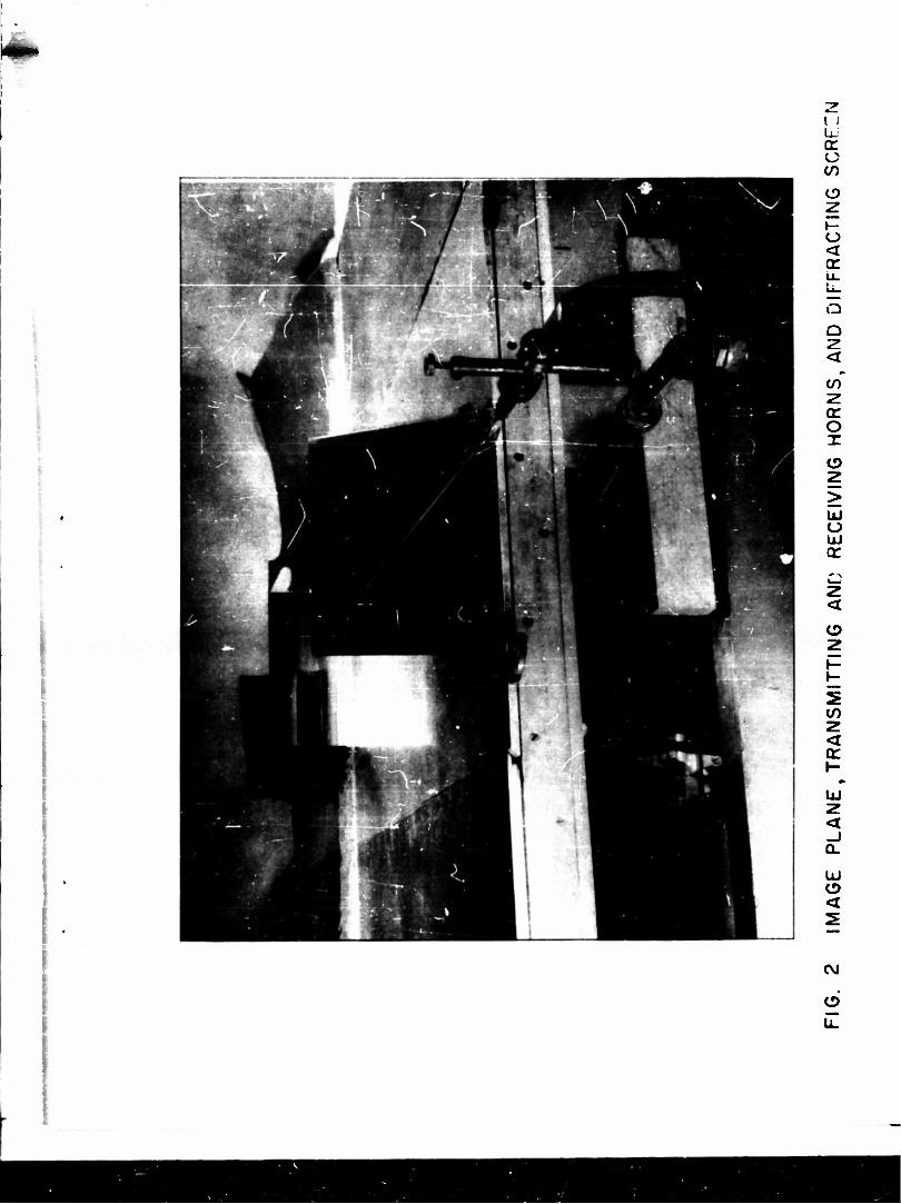
In this experiment the isolation of the screen is approximated by mounting it vertically over a conducting image plane. The image plane, which is 96 wavelengths wide by 144 wavelengths long at X = 1.25 cm, is large enough so that reflections from its edges are negligible. To make the incident wave nearly plane, at least over the region of the
aperture, a remote point source is required. In this apparatus such a source is approximated adequately with a horn radiator (Fig. 2). The horn is driven by a 2K33 klystron through a length of K-band waveguide
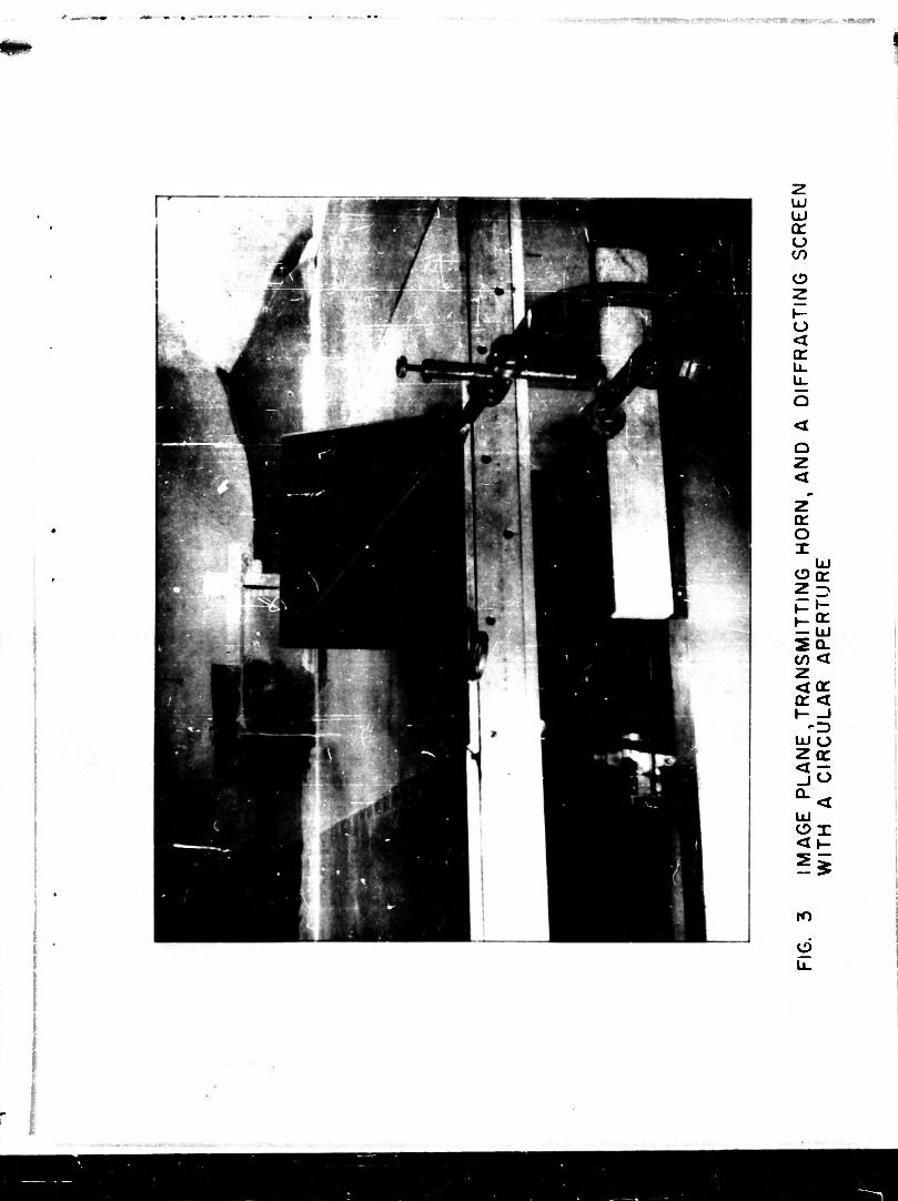
and provides the power gain required for measuring transmission co- efficients. The thin screen is shown in Figs. 2 and 3. It is made of
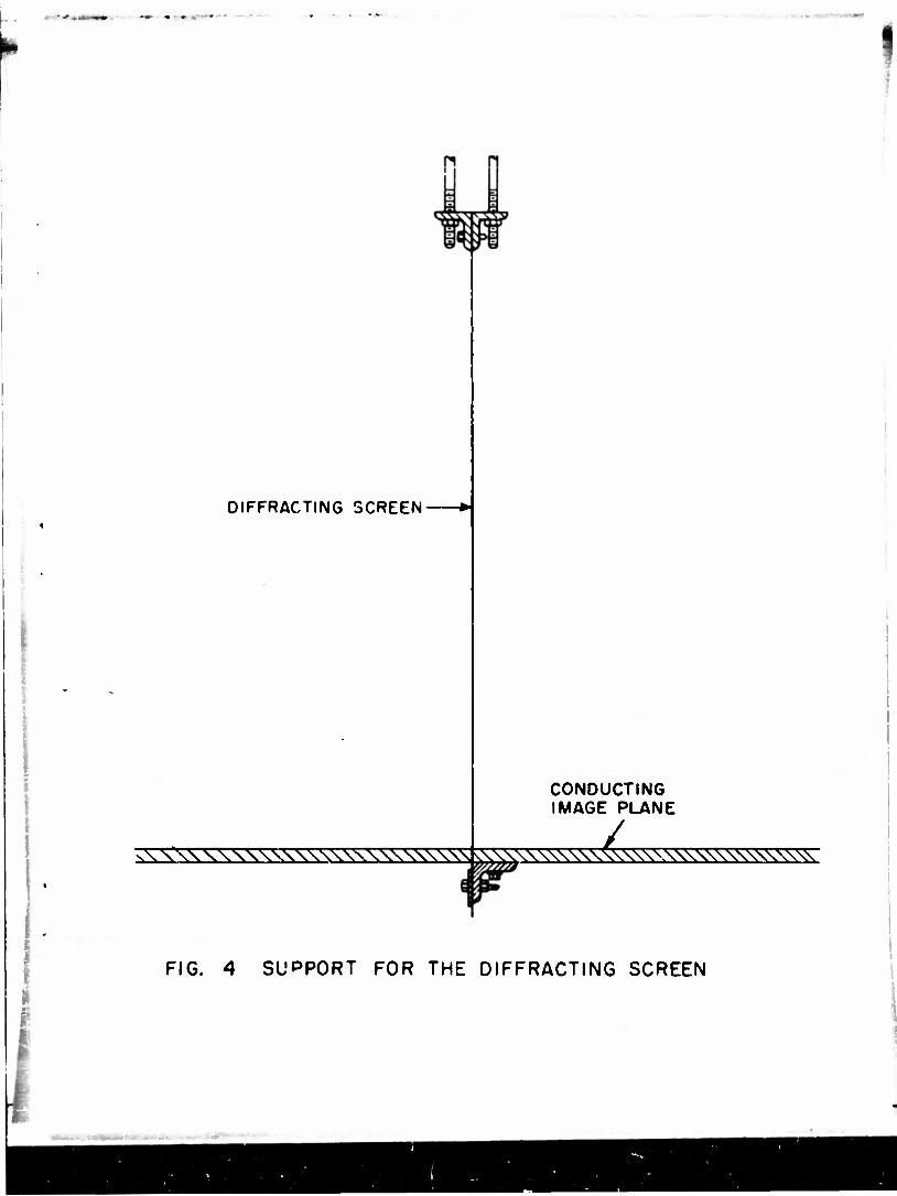
a chrome-plated steel sheet about 0.02 wavelength thick. The lower edge is fastened securely to the image plane; the upper edge is attached to a support, shown in Fig. 4, by means of which tension can be applied uniformly along the edge to keep the thin screen vertical and plane. The center section of the screen contains the half-aperture and is removable so that apertures of different sizes and shapes can be put
in place with a minimum cf effort.
With less than 20 milliwatts available from a 2K33 K-band oscillator

QC o X o
Z UJ LU cr
z
o
o
o < o:
o
»-cr
acac
o z
!*
8s!
| W
UJ
u. u. UJ o o
co co
to
<
u. O
z UJ
UJ cr =5 CO < UJ
cr o ti-
co t- z UJC/> ZUJ ocr o. =)
0UJ
LJ ^
3x
S|
o u.
cr
-z.
cr o
o < <r u_ L^
Q
O
<
CO~ Z cr o x o
O LU cr
o
CO
tr
LU O < 2
CVJ
o
UJ QC U CO
o
o tr
<
or o T
LLI (3(t 2 Z>
— UJ 5Q- CO < 2 <QC or <t »- -J
Ul o zor
°-< UJ OX <»-
ro
o u.
r I
I
DIFFRACTING SCREEN
CONDUCTING IMAGE PLANE
vV sss ssssssssssssssssss sssss^ssssss^^^^ss^ ,w>
FIG. 4 SUPPORT FOR THE DIFFRACTING SCREEN

«•.,-. —
TR165 -3-
very little energy is transmitted by a small aperture located far from the
transmitting horn. Consequently, the measurement of its transmission
coefficient, which is related to the far-zone field on the shadow side of the
screen, requires a very sensitive detector and corresponding care in
preventing leakage to the detector by paths other than through the aperture.
A simple criterion is that with the aperture closed the leakage signal must be less than noise; the requirement is met as follows:
1. The screen containing the aperture is made large enough so
so that no detectable radiation is diffracted around any of its three free edges.
2. The fourth (bottom) edge of the screen is pinched tightly in
a narrow slit in the image plane so that the joint between the two planes is not leaky.
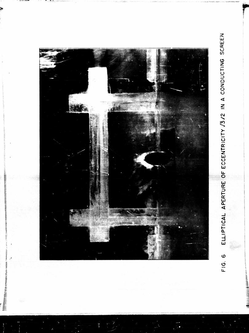
3. The aperture insert is put into intimate contact with the rest pf the diffracting screen by covering the overlapping joint
with strips of aluminum foil two wavelength* wide and 0. 0012 wavelength thick. These strips are sealed with conducting
silver paint (cf. Fig. 5 through 8).
Under these conditions no leakage signal can be detected by the receiving system, which consists of an antenna, a calibrated attenuator, and a spectrum-
analyzer. The receiving antenna is a horn located 30 wavelengths from the diffracting aperture in the direction of incidence. It is designed for optimum
directivity and flares 19 degrees in the E-plane and ZZ. 5 degrees in the H- plane from standard K-band waveguide to a rectangular aperture 11 wavelengths
wide and three wavelengths high (Fig. 2). From the horn the signal is tran- mitted by waveguide to a K-band spectrum-analyzer (TSK 2SE) through a precision variable attenuator The combination of attenuator and spectrum-
o analyzer is used as a sensitive receiver.
Ill
Definition of the Transmission Coefficient.
The analytic definition of the transmission coefficient of an aperture is

i
TR165
/ Re | 2
S
-4
EnnJ') x H* (p'MS'
S|EinV) x H1"0*^ (1)
where S is the area of the aperture and the subscript n denotes the direction of propagation of the incident plane wave,
.inc (?) = 6 K e ikn r
H^tr) hH e o ikn-
Since the aperture field distribution cannot be measured easily, this definition
is not very good in the operational sense. A better one is made available by
the analysis given in Technical Report No. 164. which makes it possible to put equation (1), into a form involving only a far-zone electric field. First, how-
ever, by changing the order of the vector double product in the integrand of (1),
it ia possible to make use of the fact that in the apertureSiTp) = H Cp)- The formula then simplifies to
Re
t = — /•- •Ll?') he C -ikfif dS' U)
SE
The integral in (2) can be interpreted readily in terms of the far-zone electric field on the shade w side of the screen. The asymptotic form of this field ia
.»k* E (?) - f x A(r.n)2-
n * OS (3)
where
A(r.n) - £ j sxEtt(p*')exp<-tk$.ir')dS'. Ajr.nj * -*- ssS.(a')«x9(-lk-
"" Comparison of this expression with (2) shows that in terms of the scattered
amplitude in the direction of incidence the transmission coefficient takes the
simple form,
t = 2« Im [h-A(n,h)]
With normal incidence n » £\ ti » y, and equation (4) becomes
(4)
(5)

z UJ u cr o (/)
o
o D Q Z o
UJ cr
cr UJ a. <
< _l 3 O (T o
m
o u.
*
• *
k •
z UJ UJ cr o t/)
e> z i- o Q Z o o
CVJ
jo
>-
O cr i- z UJ o o UJ
UJ QC D »- CC UJ a.
< o »- Q.
d UJ
CD
6
2 UJ UJ (T O </)
O
o ID O 2 O o
ro
o
UJ O O UJ
u_ o UJ <r
CL <
<
UJ
o u_

I i
u u
o
o Q
O O
UJ or 3
Q. <
UJ or <
O
GO

TR165 -5-
Equaticiv (5) can be written in terms of tbe scattered electric field by setting
T = sr in (3) and forming the scalar product with the unit vector?. The result is
/• ../N A. y A(«, z) * rx- E(£r)
e
Accordingly, 2wr 1 = 1ST |Ex<">l 9in<°E * kr>'
(6)
(7)
where C_ is the phase angle of the complex quantity E (zr). £* X
This 'rm of the transmission coefficient makes it evident that it can be
determined experimentally from a measurement of the amplitude and phase of E in the far zone of the aperture. Unfortunately, with the small amount
of power available the phase measurement is not feasible, but reasonable values of t can still be obtained by measuring IE I and estimating Q— from
the theoretical results of Technical Report No. 164. It is found that over most of the frequency range of interest sin(©E-kr) is nearly unity as shown in Fig. 9. This value checks with the optical limit of the exact theory.
iV
The Measuring Procedure
With the definitions just given, the measurement of transmission
coefficients for normal incidence is reduced to the problem of measuring the
far-zone electric field directly behind the aperture. Since this field is small and frequency sensitive, certain precautions are necessary.
In the first place, the radiation frequency must be known and held constant throughout a series of measurements. This can be accomplished with sufficient
accuracy by measuring the guide wavelength on a slotted line and monitoring
the frequency continuously with the reference pip of the spectrunn-anaJLyser. In addition, the small signal strength makes it necessary to tune all transmitting and receiving components as carefully as possible.
The actual measurement of the amplitude of the far-zone electric field for each aperture is a relatively simple matter. The diffracted wave that
is incident upon the receiving horn is proportional to |E I at a point directly behind the apexture. The resulting signal is transmitted through a section
TR165 -6-
of waveguide containing a precision attenuator to a spectrum-analyser where it is displayed on the oscilloscope (Fig. 10). By adjusting the attenuator so
that with each aperture, the signal is constant in amplitude, the relative
magnitude of E can be determined from the attenuator settings at each value of ka. The relative transmission coefficients of a group of similar apertures
are then readily calculated from equation (7), and they can be compared with theroretical results after being normalised to the limiting value of unity for large values of ka.
The apertures for which this measuring procedure was carried out are shown in Figs. 11 through 14.
V.
Comparison of Result*
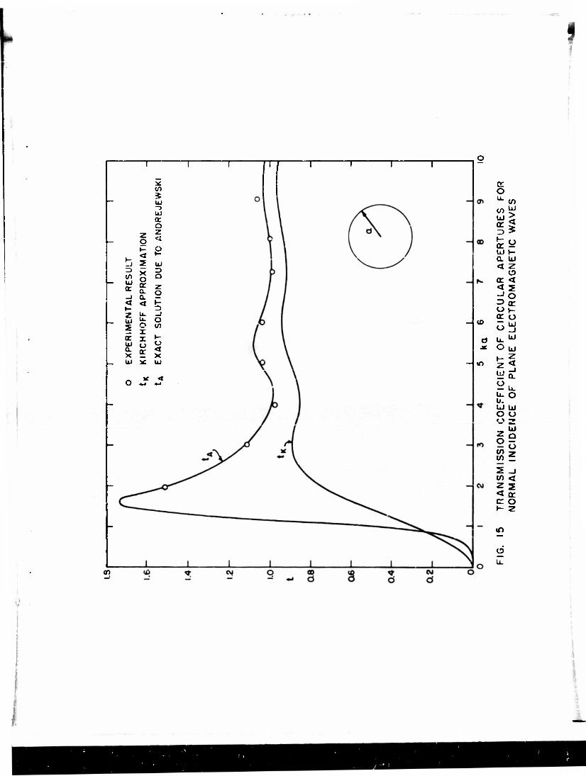
The experimental values of the transmission coefficient for circular
apertures are compared in Fig. 15 to the results of the exact theory. Good agreement is obtained over almost the entire frequency range considered. The
largest error occurs at ka « 9, and is probably due to the fact that over a large aperture the incident wave from a point source is no longer plane to the required degree of approximation.
Since the exact theory has not yet been worked out for elliptical apertures, the experimental results are compared to those obtained by the variational and Kirchhoff approximations. ' The curves are shown in Figs. 16 and 17. The remarkable agreement between the experimental result and the variational approximation probably indicates that the single-component trial field resembles
the f.rue field in the aperture quite closely when the incident electric field is polarised along the major axis o£ the ellipse. The contrast with the Kirchhoff approximation hardly needs to be emphasised; this approximation tends to-
ward the correct result only for large values of ka.
Because of analytical difficulties, the only available theoretical result for the transmission coefficient of a square aperture is the Kirchhoff approxi- mation. Unfortunately, the experimental result is also inaccurate because
the factor *in(9£ - kr) is unknown. The theoretical curve together with the experi- mentally determined values, is shown in Fig. 18. No valid comparison can be

ve ui* = (-i->!-3^) "is
fco)cv)|oo|to
fc > »-
o O QC a: »- h- z u 5 o o o o UJ UJ
u. o fe UJ UJ u (T or cc z> 3
3 H H \- or a ac UJ UJ UJ 0. a 0. < < <
_i _i Qd <t <t
3 o
_i o. 0. o cc -I
-J o UJ UJ
CJ IO < tf <
<x> <to <x>
CO o T
O b 0J b
b&>
en
CO
o
Q UJ ac UJ
5<q w8 UJ x 2 »- 0 W Nl 5
C _J
u2 1 K »- <
H < i: < m
O UJ
y£ z o < o UJ UJ w o 2? o. —
-J UJ Q. X 5 h- <
a>
u_
33«93Q N

Q:
>-
ID cr o LJ 0. CO
lJ^ o lli
o o CO
UJ X
Q UJ > < _J 0. CO
<
to
o
•
I I
FIG. II CIRCULAR APERTURE
I"'l','l
i FIG. 12 ELLIPTICAL APERTURES OF ECCENTRICITY/3/2

• » I — • * M
I 'T't'T
FIG. 13 ELLIPTICAL APERTURES OF ECCENTRICITYM/Z
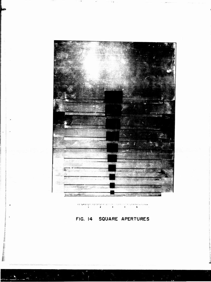
FIG. 14 SQUARE APERTURES
TT
* to * UJ "3 UJ Q: o
z o z
t- o < *-
t- _J 2 UJ 13 tn UJ
X o tr a.
a z o _l Q.
<1 <s K »- =5 z u. _) UJ U. o 2 o i </>
cc X »- UJ tj u Q. tt' < X X Ul *: UJ
If < O -~» *-*
in
0)
_|U) _
O
UJ or D t- cr UJ a <3
CO UJ >
o
or
UJ z o <
=>£ or o
UJ o _ u.w O UJ
^u.
UJ UJ o o
ie cn « 5 _i co <
51 c: o
in
o u.


I 1 1 ~| 1 i r —r-
-
1 m cvj —• 1
-
/
/ /' u
A n\ \ - / ' ul '1 -
/ L-4_o / i / 7
ii h \ / J — i \ / -
5 / V : / < 2
1 Ul
"5 a
u X g
X -* •-
1 UJ x C •- ~
O "^_i Q. O
Z Q. .S< _ <i 2 «"z _
z c CO
in <
i2x °\ z o or h- 2 t- >-<j ~ < — _J -i> *•
X r> D cc o in to UJ <x cr UJ Ul x X °^^s«s > a.
a. (t cr£
or <j _J -J> ~ UJ 2 <DD "•
cr o
u. u. o
z UJ 2 2K
X X ZZ. 3 h- X cr g2 - o o UJ ^^ "" cc ac a. Q.2 UJ X xo IS) i UJ UJO -|ro „ II 9 «
1
X 0
i
xs|a
1 1 L 1
-IS
o>
_|a>
H-
Hco
-|m
H*
-iio
HCJ
<
or o
or o u.
UJ or
t- or UJ
< CO
_,UJ
_ii- _i iu UJ 2
o u. < OS i- ° 2^ UJ o yUJ
U. UJ U- UJ UJ O 2 o <
2 O CO CO
i CO 2 < or
U. O
UJ o 2 UJ Q
O 2
CO • 00 o
CO o a
CVJ O
o u.

i8
II ^-"* w 1 1 UJ
<t> »**• tC '«/>
e> z 2 3 to Z </) o < t-
_J < 2
3 X
= ft*
cr u a x UJ
u. O X I o
-m a -loo
4s
I
JCM
Od
<
or O
a: o
< 5 UJ O
si
St O UJ
-loo u. u. UJ O o
UJ
<
Q.
C/> UJ
C/) LJ
CO
o u_
»
TR165 -7.
made except at large values of ka where the phase factor is expected to be
unity. From the results for circular and elliptical apertures, however, it
can be inferred that for small values of ka, the measured coefficients should
be smaller than those shown.
References
2.
3.
4.
8.
9.
C. Huang , On the Diffraction of Electromagnetic Waveu by Annular, EllirticaJ and Rectangular Apertures, Tech. Report 163, Craft Laboratory, Harvard University
C. Huang, Variational App rox i ma ti on s to the Diffraction by Circular and Elliptical Apertures, Tech. Repo"rt~r&4T~C~ruft Laboratory. Harvard University.
C. L. Andrews, "Diffraction Pattern in a Circular Aperture Measured in the Microwave Region, " ~T". Appl. Phys. 21. 761 (1950). fi— ~ -**• l
S. Silver, Report No. 163,Antenna Laboratory, University of California, Berkeley, 1949 M J. Ehrlich -"Diffraction of a Plane Electromagnetic Wave by a Circular Aperture and C~omple-
iry Obstacles. " PHT~Thesis. University of California^ 1951. mentai
Water A. L. Aden. "Electromagnetic Scattering from Metal and Spheres, •' PhD Thesis, Harvard University, April 19~50~
J. Sevick, "An Experimental and Theoretical Investigation of Back-Scattering Cross Sections," PhD. Thesis,Harvard University, TSnT, 1952.
R. D. Kodis, "An Experimental Investigation of Microwave Diffraction, " PhD. Thesis, Harvard University, Cambridge7~Massachusetts, May 1950. R. D. Kodis, "Diffraction Measurements at 1. 25 Centimeters, " J^p. Appl. Phys '23. 249 - 25$ (1952r
J. D. Kraus, Antennas McGraw-Hill. New York, 1950, p. 377.
C. G. Montgomery, "Technique of Microwave Measurements, " McGraw-Hill, New York, 1947, p~T55l

Additional Report* Issued by Cruft Laboratory
(under Contract N5ori-76)
in the Field of Electromagnetic Radiation
No.
Z D. D. King, "Measured Impedance of Cylindrical Dipoles, " 1946. J. Appl. Phys., Oct. 1946.
6 D. O. King, "Impedance Measurements on Transmission Line*," 1946. Proc. I.R.E.. May 1947.
8 B.C. Dunn. Jr. and R. W. P. King, "Currents Excited on a Conducting Plane. ..." 1947. Proc. I.R. E , Feb. 1948.
21 D. D. King et al, "Bolometer Amplifier for Minimum Signals," 1947. Electronics, Feb. 1948.
12 C. T. Tai, "Theory of Coupled Antennas. " 1947. Parti Proc. I.RE., April 1948; Part II, ibid, Nov. 1948.
16 Tung Chang, "Impedance Measurements of Antennas Involving Loop and Linear Elements, " 1947.
18 C. T. Tai, "Propagation of Electromagnetic Waves from a Dissipative Medium to a Perfect Dielectric, " 1947.
20 R. W. P. King, "Graphical Representation of the Characteristics of Cylindrical Antennas, " 1947.
ZZ C. H. Papas and R. W. P. King, "Radiation Resistance of End-Fire Collinear Arrays," 1947. Proc. I.R.E., July 1948.
23 R. W. P. King, "Field of Dipole with Tuned Parasite at Constant Power," 1947. Proc. I.R.E., July 1948.
25 J. V. Granger, "Low-Frequency Aircraft Antennas," 1947.
27 C. H. Papas and R. W. P. King, "Surface Currents on a Conducting Plane. . .," 1948. J. Appl. Phys. , Sept. 1948.
28 C. T. Tai, "Reflection and Refraction of a Plane Electro- magnetic Wave. ..." 1948.
32 C. H. Papas and R. King, "Currents on the Surface of an Infinite Cylinder," 1948. Quart. Appl. Math. , Jan. 1949.
-i-

-11-
35
39
40
41
42
43
44
46
47
48
49
50
52
53
55
56
58
P. Conlev. "Impedinc* Measurements with Open-Wire Lines," 1948. J. Appl. Phys., Nov. 1949.
S. B. Cohn, "Theoretical and Experimental Study of a Waveguide Filter Structure," 1948
C. T. Tai, "Reflection of Plane Electromagnetic Waves from Perfectly Conducting Grounded Half-Cylinder, " 1948.
R W. P. King, "Theory of Antennas Driven from a Two-Wire Line," 1948. J. Appl. Phys. , Sept. 1949.
J. V. Granger, "Note on Broad-Band Impedance Characteristics of Folded Dipoles, " 1948.
D. G. Wilson and R. King, "Measurement of Antenna Impedance Using Receiving Antenna, " 1946
£. Halie'n, "Properties of Long Antennas, " 1948. J. Appl. Phys. , Dec. 1948.
E. Halie'n, "Admittance Diagrams for Antennas. 1948.
C. T. Tai, "On the Theory of Bicouicai Antennas," 1948. J. Appl. Phys. , Dec. 1948.
K. Tomiyasu, "Problems of Measurement on Two-Wire Lines with Application to Antenna Impedance, " 1948. Condensed version, J. Appl. Phys. , Oct. 1949-
E. Hallen. "Traveling Waves and Unsymmetrically Fed Antenna* " 1948.
D. D. King, "Measurement and Interpretation of Antenna Scattering, " 1948.
C. H. Papas and R. King, "Input Impedance of Wide-Angle Conical Antennas," 1948. Proc. I.R.E , Nov. 1949.
D. K. Reynolds, "Surface-Current and Charge Measurements on Flat Metal Sheets, " 1948.
C. T. Tai. "Study of the EMF Method, " 194a J. Appl. Phys. , July 1949.
T. W. WinterniU, "The Cylindrical Antenna Center-Driven by a Two^wire Open Transmission Line," 1948. Quart. Appl. Math., 1949.
C. H. Papas, "On the Infinitely Long Cylindrical Antenna," 1948. J. Appl. Phys., May 1949-

-iii-
t I C. H. Papas, "Radiation from a Transverse Slot in an Infinite Cylinder." 1948. J. Math, and Phys. , Jan. 1950.
63 J. V. Granger and N. G. Airman, "Full-Scale Aircraft Antenna Measurements," 1949.
66 T. Morita, "Measurement cf Current and Charge Distributions on Cylindrical Antennas, " 1949 Proc. I.R.E. , Aug. 1950.
67 T. Morita and C. £. Faflick, "Measurement of Current Distributions along Coupled Antennas. . . ," 1949.
69 J. E. Storer and R. King, "Radiation Resistance of a Two-Wire Line." 1949.
70 J. V. Granger, "Shunt-Excited Flat-Plate Antennas. . .," 1949. Proc. I.R.E., March 19 50.
71 72 73
74
75
B. C. Dunn, Jr., "Microwave Field Measurements, " I (with R. King), II and III, 1949.
R. King and K. Tomiyasu, "Terminal Impedance and Generalised Two-Wire Line Theory," 1949. Proc. I.R. E., Oct. 1949.
C. T. Tai, "Application of a Variations! Principle to the Study of Biconical Antennas, " 1949.
76 C. H. Papas, "Radiation from a Circular Diffraction Antenna," 1949.
77 C. T. Tai, "On Radiation and Radiating Systems in the Presence of a Dissipative Medium, " 1949.
78 J. V. Granger and T. Moxita, "Current Distribution on Aircraft, " 1949.
81 K. Tomiyasu, "Loading and Coupling Effects of Standing-Wave Detectors," 1949. Proc. I.R.E. , Dec. 1949.
83 C. H. Papas, "Diffraction by a Cylindrical Obstacle, " 1949. J. Appl. Phys., April 1950.
84 R. King. "Theory of N Coupled Parallel Antennas,t! 1949. J. Appl. Phys., Feb. 1950.
86 K. Tomiyasu, "Unbalanced Terminations on a Sfc<*ld«J-Pair Line," 1949.
91 R. King, "Theory of Collincar Antennas," 1949.

-IV-
92 C. H. Papas and R. King, "Radiation from Wide-Angle Conical Antennas. . . ," 1949- Proc. I. RE. . Nov. 1949.
93 R. King, "Asymmetrically Driven Antenna* and the Sleeve Dipole," 1949.
94 T. Morita, E. O. Hartig, and R King, "Measurement of Antenna Impedance. ..." (Supplement to T. R. 43), 1949.
95 C. P. Hsu, "Theory of Helical Waveguides and Helical Radiators," 1950.
96 R. King, "Theory of V-Antennas, " 1950.
93 O. J. Angelahos, "Current and Charge Distributions on Antennas and Open-Wire Lines," 1950.
100 H. Levine and C. H. Papas, "Theory of the Circular Diffraction Antennas," 1950.
101 J. £. Storer, "Variadonal Solution to the Problem of the Symmetrical Cylindrical Antenna," 1950.
104 C. Wheeler. "Coupled Slot Antennas, " October 25, 1950.
105 R. D. Kodis, "An Experimental Investigation of Microwave Di/fraction, " 1950.
107 E. O. Hartig, "Circular Apertures and their affects on Half. Dipole Impedances," 1950.
108 E. O. Hartig, '"A Study of Coaxial-lane Discontinuities Using a Variational Method, " 1950.
109 E. O. Hartig, "An Experimental and Theoretical Discussion of the Circular Diffraction Antenna, " 1950.
118 R. King, "Self- and Mutual Impedances of Parallel Identical Antennao, " 1950.
119 J. E. Storer, "The Impedance of an Antenna over a Large Circular Screen," 1950. J. Appl. Phys. , August 1951.
121 R. King, "Theory of Collinear Antennas, II," 1950. J. Appl. Phys. , December 1950.
122 J. Taylor and T. Morita, "Antenna Pattern-Measuring Range. 1951.
126 J. E. Storer, "The Radiation Pattern of an Antenna over a Circular Ground Sr rten, " 195'.
-V-
128 J Taylor, "The Sleeve Antenna, »• 1951.
129 T. E. Roberta, Jr., "Currents Induced on an Infinitely Long Wire by a Slice Generatqr, " 1951.
130 R King, "A Dipole with a Tuned Parasite: Theory and experiment, " 1951. J.l.E.E. , January 1952.
132 R King, "An Improved Theory of the Receiving Antenna," June 1951.
134 T. E. Roberts,Jr.. "Properties of a Single -Wire Line, " 1951.
138 C. Huang and R. D Kodis, "Diffraction by Spheres and Edges at 1. 25 Centimeters, " 1951.
139 T. E. Roberts, Jr. , "An Experimental Investigation of the Single- Wire Transmission Line," 1952.
141 R. Xing, "Theory of Electrically Short Transmitting and Receiving Antennas, " 1952.
146 C. Moritz, "The Coupled Receiving Antenna, I., » 1952.
147 C. Moritz. "The Coupled Receiving Antenna, II.." 1952.
148 C. H. Papas and D B. Brick, "Radiation of the Boss Antenna," 1952.
149 J. Sevick and J. E. Storer, "A General Theory of Plane-Wave Scattering from Finite Conducting Obstacles with Application to the Two-Antenna Problem, " 1952.
150 J. Sevick, "Experimental and Theoretical Results on the Back-Scattering Cross Section of Coupled Antennas, " 1952.
151 J. Sevick, "An Experimental Method of Measuring Back-Scattering Cross Sections of Coupled Antennas," 1952.
152 J. E. Storer, "Wave Propagation in a Two-Dimensional Periodic Medium," 19 52.
153 R. V. Row, "Microwave Diffraction Measurements in a Parallel - Plate Region," 1952.
154 R. King, "An Alternative Method of Solving Hal)en's Integral Equation and its Application to Antennas near Resonance," 1952.
155 P. A. Kennedy and R. King, "Experimental and Theoretical Impedances and Admittances of Center-Driven Antennas," April 1953.
159 L. S. Sheingold, "The Susceptance of a Circular Obstacle to an Incident Dominant Circular-Electric Wave," 1952.
-vi-
160 J. £. Storer, L. S. Sheingold, and S. Stein, "A Simple Graphical Analysis of Waveguide Junctions," 1952.
161 R. D. Turner, "Scattering of Plane Electromagnetic Radiation by .-n Infinite Cylindrical Mirror, " May 15, 1953.
162 T. Morita and L. S. Sheingold. "A Coaxial Magic-T, " 1952.
163 C. Huang, "On the Diffraction of Electromagnetic Waves by Annular, Elliptical and Rectangular Apertures, " May 1953.
170 R. V. Row, "Electromagnetic Scattering from Two Parallel Conducting Circular Cylinders," May 1, 1953.
172 D. B. Brick, "The Radiation of a Hertaian Dipole over a Coated Conductor," May 10, 1950.
173 R. Turner and A. F. Downey, "A Tabulation of the Fresnei Integrals. " March 15, 1953.
174 R. King, "End-Correction for Coaxial Line When Driving an Antenna over a Ground Screen. " June 15, 1953.
180 J. E. Storer, 'Modification of Standard Network Synthesis Techniques to Use Lossy Elements." June 20, 1953.
i
I
I

Antennas
£I5TJU_BJJ^TK)N
Office of iNavaJ Research (427) Navy Department Washington 25, D C
Office of Naval Research (460) Navy Department Washington, 25, D C
Chief, Bureau of Ordnance (Re4f) Navy Department Washington 25, D. C.
Chief, Bureau of Ships (810) Navy Department Washington 25, D. C.
Chief, Bureau of Ships (833) Navy Department Washington 25, D. C.
Chief, Bureau of Aeronautics (£L-51) Navy Department Washington 25, D. C.
Chief of Naval Operations (Op-413) r'avy Department Washington 25, D. C.
Chief of Naval Operations (Op-20) Navy Department Washington 25, D. C.
Chief of Naval Operations (Op-32) Navy Department Washington 25, D. C.
Naval Research Laboratory (2027) Bellevue D. C.
Naval Research Laboratory (2020) Bellevue D. C
Naval Research Laboratory (3480) Bellevue D. C.
Naval Ordnance Laboratory White Oak Maryland

Antennas -2-
DISTRIBUTION
2 U.S. Naval Electronics Laboratory San Diego 52 California
1 Naval Air Development Center (AAEL) Johnsville Pennsylvania
1 U.S. Navy Underwater Sound Laboratory New London Connecticut
U. S. Navy Office of Naval Research Branch Offices:
2 Boston 1 New York 1 Chicago 1 San Francisco 1 Pasadena
i U. S. Navy, Office of Naval Research U. S. Navy 100, Fleet Post Office New York, N. Y.
Librarian U. S. Naval Post Graduate School Monterey, California
U. S. Coast Guard (EEE) 1300 E Street. N. W. Washington, D. C.
Research and Development Board Pentagon Building- Washington 25, D. C.
National Bureau of Standards Department of Commerce Washington, D. C. Attention: Dr. N. Smith
Naval Ordnance Development Unit Johns Hopkins University Radiation Laboratory Homewood Campus Baltimore 18, Maryland Attention: Dr. C. R. L*rkin

Antennas
91 £ TJUJM^T 10 £ Applied Physics Laboratory Johns Hopkins University 8621 Georgia Avenu- Silver Spring, Maryland
Library of Congress Navy Research Section Washington, D. C.
Massachusetts Institute of Technology Research Laboratory of .Electronics Cambridge 39, Massachusetts Attention: Professor L. i. Chu
Stanford University Stanford, California Attention: Professor K. Sp&ngenberg
University of Illinois Urbana, Illinois Attention: Professor E. C. Jordan
Ohio State University Columbus, Ohio Attention: Dr. V. H. Rumsey
Cornell University Ithaca, New York Attention: Professor C. P. Burrows
University of California Berkeley, California Attention: Electrical Engineering Department
Oregon State College Corvallis, Oregon Attention: Professor J. J. Brady
1 University of Texas Austin, Texas Attention: Electrical Engineering Department
Librarian National Bureau of Standards Washington 25, D. C.
Librarian Radio Corporation of America RCA Laboratories Princeton, N«»w Jersey

Antennas -4-
DISTBIBUTION
1 Exchange and Gift Division Library- of Congress Washington 25, D. C. Attn: fLxchanoe Division
American and British
Ballistic Research Laboratories White Sands Proving Ground Las Craces, New Mexico
Profesi«or Morris) Kline Mathematics R?search Group New Yotrk University 45 As toe- Place New York, N. Y.
Technical Library Bell Tel ephone Laboratories Murray Hill Labcrrtsry MurrayZHili, New Jersey
Technical Library Federal Telecommunications Laboratories Inc. 500 Washington Avenue Nutley 1st), New Jersey
Library Philco C orporation Philadelphia 34, Pennsylvania
Library of the College of Engineering University Heights Library New York University New YOT* 53, N. Y.
Library Central Radio Propagation Laboratory National Bureau of Standards Washington 25, D. C.
Dr. Je>hs V. N. Granger Stanford Research Institute Stanford, California
Document and Research Ray the OP Manufacturing Company Equipment Engineering Division Newton 53, Massachusetts
Antennas
DISTRIBUTION
1 Dr. A. G. Hill Lincoln Laboratory Massachusetts Institute of Technology Cambridge 38, Massachusetts
1 Professor H. G. Booker Department of Electrical Engineering Cornell University Ithaca, New York
50 Signal Corps, Transportation Officer Asbury Park New Jersey
50 Chief, Administration Section Electronic:* Research Division Air Force Cambridge Research Center Cambridge, Massachusetts
1 Signal Corps Liaison Office Massachusetts Institute of Technology Attention: Mr. RE Campbell
1 Document Room Research Laboratory of Electronics Massachusetts Institute of Technology Attention: Mr. Hewitt
1 Library Watson Laboratories, AMC Red Bank, New Jersey (ENAGS1)