the main features of these systems are shown in fig. the ... · spherical measuring machine having...
TRANSCRIPT
ME6504-METROLOGY AND MEASUREMENTS
Mechanical Engineering
Fourth Semester
UNIT- 3
Part A
1. Mention the application of CMM. [M/J 16]
CMM's to find application in automobile, machine to, electronics, space and many other
large companies.
These are best suited for the test and inspection of test equipment, gauges and tools.
For aircraft and space vehicles of hundred Percent inspections is carried out by using
CMM.
CMM can be used for determining dimensional accuracy of the component.
CMM can also be used for sorting tasks to achieve optimum pacing of components within
tolerance limits.
2. Write the advantages of machine vision systems. [M/J 16]
Reduction of tooling and fixture cash.
Elimination of need for precise part location.
Integrated automation of dimensional Verification.
Defect detection.
3. Why is monochromatic light used in interferometry instead of white light? [N/D 16]
Monochromatic light is used to suit radiations other than light. A most unusual
feature of the interferometer is its high tolerance to large misalignments of its optical
elements.
4. What are the four basic types of machine vision system? .[N/D 16]
Image formation.
Processing of image.
Analyzing the image.
Interpretation of image.
5. What are touch trigger probes? [N/D 15]
The main features of these systems are shown in fig. the ―buking mechanism‖ is a three point
bearing, the contacts of which are arranged at 1200 around the circumference. These contacts
act as electrical micro switches. When being touched in army probing direction , one or more
contacts are lifted off and the current is broken, thus it generates a pulse.
6. Mention the disadvantages of CMM. [N/D 15]
The table and probe may not be in perfect alignment.
The stylus may have run out.
The stylus moving in z-axis may have some perpendicularity errors.
Stylus while moving in x and y direction may not be square to each other.
There may be errors in digital system.
7. What is the principle of hot wire anemometer?
When a fluid flows over a heated surface heat is transferred from the surface and so the
temperature reduces. The rate of reduction of temperature is related to flow rate.
8. What is the principle involved in fluid expansion thermometer?
Change in pressure in the bulb is taken as an indication of the temperature.
9. Define resolution. Resolution is defined as the smallest increment of quantity being measured which can be
detected with certainty being measured which can be detected with certainty by an instrument. 10. What is interferometer?
Interferometer is optical instruments used for measuring flatness and determining the lengths of slip gauges by direct reference to the wavelength of light.
11. What is crest and trough? The light is a form of energy being propagated by electromagnetic waves, which is a sine
curve. The high point of the wave is called crust and the low Point is called is trough. 12. What is wavelength?
The distance between two crusts or two troughs is called the wavelength. 13. What are the various geometrical checks made on machine tools?
Straightness of guide ways and slide ways of machine tool Flatness of machine tables and slide ways Parallelism, equidistance and alignment of the slide ways True running and alignment of shaft and spindle
14. Why the laser is used for alignment testing? The alignment tests can be carried out over greater distances and to a greater degree of
accuracy using laser equipment. Laser equipment produces real straight line, whereas an alignment telescope provides a, imaginary line that cannot be seen in space.

Part B
1. Explain the working of Laser Interferometer. [16] [M/J 16]
Laser Interferometer
It is possible to maintain the quality of interference fringes over longer distance when
lamp is replaced by a laser source:
Laser interferometer uses AC laser as the light source and the measurements to be
made over longer distance.
Laser is a monochromatic optical energy, which can be collimated into a directional beam
AC.
Laser interferometer (ACLI) has the following advantages.
1. High repeatability
2. High accuracy
3. Long range optical path
4. Easy installations
5. Wear and tear
Schematic arrangement of laser interferometer is shown in fig. Two-frequency
Zeeman laser generates light of two slightly different frequencies with opposite circular
polarizations.
These beams get split up by beam splitter B One part travels towards B and from there to
external cube corner here the displacement is to be measured.
This interferometer uses cube corner reflectors which reflect light parallel to its angle of
incidence.
Beam splitter B2 optically separates the frequency f1 which alone is sent to the movable
cube corner reflector.

The second frequency f1 from B2 is sent to a fixed reflector which then rejoins f1 at the
beam splitter B2 to produce alternate light and dark interference flicker at about 2
Megacycles per second. Now if the movable reflector moves, then the returning beam
frequency Doppler-shifted slightly up or down by ( f1 )
Thus the light beams moving towards photo detector P2 have frequencies f2 and (f1 ± f1)
and P2 changes these frequencies into electrical signal.
Photo detector P2 receive signal from beam splitter B2 and changes the reference
beam frequencies f1and f2 into electrical signal.
An AC amplifier A1 separates frequency difference signal f2– f1 and A2 separates
frequency difference signal [ f2 - (f1 ± f)].
The pulse converter extracts f , one cycle per half wavelength of motion. The up-down
pulses are counted electronically and displayed in analog or digital form.
2.) Explain different types of CMM and their constructional features [16] [M/J 16]
Types of CMM:
The various types of co-ordinates measuring machine are, Cantilever type
1. Bridge type
2. Horizontal boring type
3. Vertical boring type.
Cantilever type:
It is easy to load and unload, but it is most sensitive to mechanical error because of sag or
deflction in y-axis beam.

Bridge type:
It is difficult to load but less sensitive to mechanical errors. A bridge type machine is
also available in which the complete bridge can slide in y-direction.
Horizontal boring mill type:
It is best suited for large heavy work pieces.
Working principle:
When the distance is measured between two holes using CMM the work piece should be
clomped to the worktable and obliged for their measuring slides x, y and z now, the tapered
probe tip is rated in first the hole and probe position digital read out is set to zero.
The probe is then moved to successive holes, the read out represent the co-ordinate part
location with respect to the datum hole.
Automatic recording and data processing units are provide to carryout complex
geometric and statistical analysis. It is shown is above fig.
Special co-ordinate machines are provided both linear and rotary axes. These machines
can measure various feature of parts whose shapes are objects of revolution like comes, cylinder
and hemi and pharos.
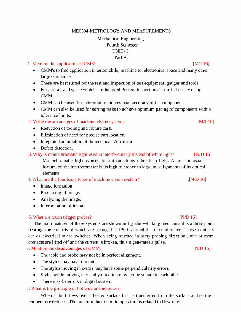
Spherical measuring machine having motions of their measuring head in R,Q and
direction used for inspecting parts that are basically spherical.
Advantages of CMM:
The main a advantage of co-ordinate measuring machine is the quicker inspection and
accurate measurements
3. With a neat diagram explain the working of AC laser interferometer. [10] [N/D 16]
Laser Interferometer
It is possible to maintain the quality of interference fringes over longer distance when
lamp is replaced by a laser source:
Laser interferometer uses AC laser as the light source and the measurements to be made
over longer distance.
Laser is a monochromatic optical energy, which can be collimated into a directional beam
AC.
Laser interferometer (ACLI) has the following advantages.
1. High repeatability
2. High accuracy
3. Long range optical path
4. Easy installations
5. Wear and tear
Schematic arrangement of laser interferometer is shown in fig. Two-frequency
Zeeman laser generates light of two slightly different frequencies with opposite circular
polarizations.
These beams get split up by beam splitter B One part travels towards B and from there to
external cube corner here the displacement is to be measured.

This interferometer uses cube corner reflectors which reflect light parallel to its angle of
incidence.
Beam splitter B2 optically separates the frequency f1 which alone is sent to the movable
cube corner reflector.
The second frequency f1 from B2 is sent to a fixed reflector which then rejoins f1 at the
beam splitter B2 to produce alternate light and dark interference flicker at about 2
Megacycles per second. Now if the movable reflector moves, then the returning beam
frequency Doppler-shifted slightly up or down by ( f1 )
Thus the light beams moving towards photo detector P2 have frequencies f2 and (f1 ± f1)
and P2 changes these frequencies into electrical signal.
Photo detector P2 receive signal from beam splitter B2 and changes the reference
beam frequencies f1and f2 into electrical signal.
An AC amplifier A1 separates frequency difference signal f2– f1 and A2 separates
frequency difference signal [ f2 - (f1 ± f)].
The pulse converter extracts f , one cycle per half wavelength of motion. The up-down
pulses are counted electronically and displayed in analog or digital form.
4.) What is the principle of laser?. [06] [N/D 16]
The photon emitted during stimulated emission has the same energy, phase and frequency
as the incident photon.
This principle states that the photon comes in contact with another atom or molecule in
the higher energy level E2 then it will cause the atom to return to ground state energy level E,
by releasing another photon.
The sequence of triggered identical photon from stimulated at in is known as stimulated
emission. This multiplication of photon through stimulated emission leads to coherent,
powerful, monochromatic, collimated beam of light emission. This light emission is called
laser

5) List out the advantages of CMM. [06] [N/D 16]
The inspection rate is increased
Accuracy is reduced.
Operator's error can be minimized. Skill of the operator is reduced.
Reduction in calculating, recording and set up time.
No need of GO/NOGO gauges.
Reduction of scrap and good part rejection.
6) Briefly explain the calibration of three co-ordinates measuring machine with sketch.
Calibration of three co-ordinates measuring machine: [10] [N/D 15]
The optical setup for the x-axis calibration is shown in fig below.
In this fig. the laser head is mounted on the tripod stand and its height is adjusted
corresponding to the working table of CMM. The interferometer contains a polarized beam
splitter which F1 components of the laser beam.
Now, let the F2 component passes through it. The ratio refactor refocus the laser beam
back along a live parallel to the original beam by twice the distance. This is made up of polished
trihedral glass prism. For distance measurement, the F1and F2becomes that leaves the laser
head are aimed at the interferometer which splitter F1and F2 via polarizing beam splitter.
In two beams, the components F1, becomes the fixed distance path, and F2is sent to a
target which reflects it back to the interferometer relive motion behead the interferometer. The
measurement receiver photo detector in the laser head reads a frequency6 difference given by F1-
F2 F2

Now, the difference F1-F2 F2signal that is returned from the external interferometer is
compared in the measurement display unit to the F1-F2 reference signals.
Difference, F2 in related to the velocity and hence to the distance. The longitudinal
microscope of CMM is set at zero. The CMM microscope is then set at the following points and
reading are taken,
For 1 to 10 mm, the measurement is taken for every mm.
For 10 to 200mm, the measurement is taken in steps of 10mm
The accuracy of linear displacement measurement is affected by change in air
temperature, pressure and humidity. The automatic compensation for length change is provided by
the materials sensor attached to the machine similar readings for y and z axis are taken the optical
arrangement for y and z axis are shown in fig.
7) Explain the working principle of a Michelson interferometer with a neat diagram.[10] [N/D 15]
Michelson Interferometer
Michelson interferometer consists of a monochromatic light source a beam splitter and
two mirrors.
The schematic arrangement of Michelson interferometer is shown in fig. The
monochromatic light falls on a beam splitter, which splits the light into two rays of equal
intensity at right angles. One ray is transmitted to mirror M1and other is reflected through
beam splitter to mirror M2.
From both these mirrors, the rays are reflected back and these return at the semi-
reflecting surface from where they are transmitted to the eye.
Mirror M2 is fixed and mirror M1is movable. If both the mirrors are at same distance from
beam splitter, then light will arrive in phase and observer will see bright spot due to
constructive interference.
If movable mirror shifts by quarter wavelength, then beam will return to observer 1800out
of phase and darkness will be observed due to destructive interference.

Michelson interferometer consists of a monochromatic light source a beam splitter and two
mirrors. The schematic arrangement of Michelson interferometer is shown in fig. The
monochromatic light falls on a beam splitter, which splits the light into two rays of equal intensity
at right angles. One ray is transmitted to mirror M1 and other is reflected through beam splitter to
mirror M2,. From both these mirrors, the rays are reflected back and these return at the semi
reflecting surface from where they are transmitted to the eye. Mirror M2 is fixed and mirror M1 is
movable. If both the mirrors are at same distance from beam splitter, then light will arrive in phase
and observer will see bright spot due to constructive interference.
If movable mirror shifts by quarter wavelength, then beam will return to observer 1800 out of
phase and darkness will be observed due to destructive interference Each half-wave length of
mirror travel produces a change in the measured optical path of one wavelength and the reflected
beam from the moving mirror shifts through 360° phase change. When the reference beam reflected
from the fixed mirror and the beam reflected from the moving mirror rejoin at the beam splitter,
they alternately reinforce and cancel each other as the mirror moves. Each cycle of intensity at the
eye represents l/2 of mirror travel. When white light source is used then a compensator plate is
introduced in each of the path of mirror M1 So that exactly the same amount of glass is introduced
in each of the path.
To improve the Michelson interferometer,
Use of laser the measurements can be made over longer distances and highly accurate
measurements when compared to other monochromatic sources.
Mirrors are replaced by cube-corner reflector which reflects light parallel to its angle of
incidence.
Photocells are employed which convert light intensity variation in voltage pulses to give
the amount and direction of position change.
8) Draw and explain Laser Telemetric system. [16] [N/D 15]
Laser Telemetric system:
Laser telemetric system is a non-contact gauge that measures with a collimated laser
beam. It measures at the rate of 150 scans per second.

It basically consists of three components, a transmitter, and a receiver and processor
electronics. The transmitter module produces a collimated parallel scanning laser beam
moving at a high constant, linear speed.
The scanning beam appears a red line. The receiver module collects and phonetically
senses the laser light transmitted past the object being measured.
The processor electronics takes the received signals to convert them 10 a convenient
form and displays the dimension being gauged.
The transmitter contains a low power helium-neon gas laser and its power supply, a
specially designed collimating lens, a synchronous motor, a multi-faceted, reflector
prism, a synchronous pulse photo detector and a protective replaceable window.
The high speed of scanning permits on line gauging and thus it is possible to detect
changes in dimensions when components are moving on a continuous product such as in
rolling process moving at very high speed.
There is no need of waiting or product to cool for taking measurements. This system can
also be applied on production machines and control then with closed feedback loop
Since the output of this system is available in digital form, it can run a process
controller limit alarms can be provided and output can be taken on digital printer.
9) With a neat sketch, explain the components of AC LASER interferometer.
(i) Two frequency Laser source
It is generally He-Ne type that generates stable coherent light beam of two frequencies, one
polarized vertically and another horizontally relative to the plane of the mounting feet. Laser
oscillates at two slightly different frequencies by a cylindrical permanent magnet around the
cavity. The two components of frequencies are distinguishable by their opposite circular

polarization. Beam containing both frequencies passes through a quarter wave and half wave
plates which change the circular polarizations to linear perpendicular polarizations, one vertical
and other horizontal. Thus the laser can be rotated by 90°about the beam axis without affecting
transducer performance. If the laser source is deviated from one of the four optimum positions, the
photo receiver will decrease. At 45° deviation the signal will decrease to zero.
(ii) Optical elements a) Beam splitter
Sketch shows the beam splitters to divide laser output along different axes. These divide
the laser beam into separate beams. To avoid attenuation it is essential that the beam splitters must
be oriented so that the reflected beam forms a right angle with the transmitted beam. So that these
two beams: are coplanar with one of the polarization vectors of the input form.
Beam Splitter
b) Beam benders
These are used to deflect the light beam around corners on its path from the laser to each
axis. These are actually just flat mirrors but having absolutely flat and very high reflectivity.
Normally these are restricted to 90° beam deflections to avoid disturbing the polarizing vectors.
c) Retro reflectors
These can be plane mirrors, roof prism or cube corners. Cube corners are three mutually
perpendicular plane mirrors and the reflected beam is always parallel to the incidental beam. Each
ACLI transducers need two retro reflectors. All ACLI measurements are made by sensing
differential motion between two retro reflectors relative to an interferometer. Plane mirror used as
retro reflectors with the plane mirror interferometer must be flat to within 0.06 micron per cm.
(iii) Laser head’s measurement receiver
During a measurement the laser beam is directed through optics in the measurement path
and then returned to the laser head is measurement receiver which will detect part of the returning
beam and a doppler shifted frequency component.
(iv) Measurement display
It contains a microcomputer to compute and display results. The signals from receiver and
measurement receiver located in the laser head are counted in two separate pulse converter and
subtracted. Calculations are made and the computed value is displayed. Other input signals for
correction are temperature, co-efficient of expansion, air velocity etc., which can be displayed.
10) Explain the causes of error in CMM.
The table and probes are in imperfect alignment. The probes may have a degree of run out
and move up and down in the Z-axis may cause perpendicularity errors. So CMM should be
calibrated with master plates before using the machine.

Dimensional errors of a CMM is influenced by
1. Straightness and perpendicularity of the guide ways.
2. Scale division and adjustment.
3. Probe length.
4. Probe system calibration, repeatability, zero point setting and reversal error.
5. Error due to digitization.
6. Environment
Other errors can be controlled by the manufacture and minimized by the measuring
software. The length of the probe should be minimum to reduce deflection.
The weight of the work piece may change the geometry of the guide ways and therefore,
the work piece must not exceed maximum weight.
Variation in temperature of CMM, specimen and measuring lab influence the uncertainly of
measurements.
Translation errors occur from error in the scale division and error in straightness
perpendicular to the corresponding axis direction.
Perpendicularity error occurs if three axes are not orthogonal.
11) Write the advantages, disadvantages and application of CMM.
Application
Co-ordinate measuring machines find applications in automobile, machine tool,
electronics, space and many other large companies.
These machines are best suited for the test and inspection of test equipment, gauges and
tools.
For aircraft and space vehicles, hundred percent inspections is carried out by using
CMM.
CMM can be used for determining dimensional accuracy of the components.
These are ideal for determination of shape and position, maximum metal condition,
linkage of results etc. which cannot do in conventional machines.
CMM can also be used for sorting tasks to achieve optimum pairing of components
within tolerance limits.
CMMs are also best for ensuring economic viability of NC machines by reducing their
downtime for inspection results. They also help in reducing cost, rework cost at the
appropriate time with a suitable CMM.
Advantages
The inspection rate is increased.
Accuracy is more.
Operators error can be minimized.
Skill requirements of the operator is reduced.
Reduced inspection fixturing and maintenance cost
Reduction in calculating and recording time.
Reduction in set up time.
No need of separate go / no go gauges for each feature.
Reduction of scrap and good part rejection.
Reduction in off line analysis time.

Simplification of inspection procedures, possibility of reduction of total inspection time
through use of statistical and data analysis techniques
Disadvantages
The lable and probe may not be in perfect alignment.
The probe may have run out.
The probe moving in Z-axis may have some perpendicular errors.
Probe while moving in X and Y direction may not be square to each other.
There may be errors in digital system.
12) Write the Basic concept of machine vision system
Machine Vision System The schematic diagram of a typical vision system is shown. This system involves image
acquisition; image processing Acquisition requires appropriate lighting. The camera and store
digital image processing involves manipulating the digital image to simplify and reduce number of
data points. Measurements can be carried out at any angle along the three reference axes x y and z
without contacting the part. The measured values are then compared with the specified tolerance
which stores in the memory of the computer.
The main advantage of vision system is reduction of tooling and fixture costs, elimination of
need for precise part location for handling robots and integrated automation of dimensional
verification and defect detection.
Principle Four types of machine vision system and the schematic arrangement is shown
1. Image formation.
2. Processing of image in a form suitable for analysis by computer.
3. Defining and analyzing the characteristic of image.
4. Interpretation of image and decision-making.

For formation of image suitable light source is required. It consists of incandescent
light, fluorescent tube, fiber optic bundle, and arc lamp. Laser beam is used for triangulation
system for measuring distance. Ultraviolet light is used to reduce glare or increase contrast.
Proper illumination back lighting, front lighting, structured light is required. Back lighting is used
to obtain maximum image contrast. The surface of the object is to be inspected by using front
lighting. For inspecting three-dimensional feature structured lighting is required. An image sensor
vidicon camera, CCD camera is used to generate the electronic signal representing the image.
The image sensor collects light from the scene through a lens, using photosensitive target,
converts into electronic signal.
Vidicon camera
Image is formed by focusing the incoming light through a series of lenses onto the
photoconductive faceplate of the vidicon tube. The electron beam scans the photoconductive
surface and produces an analog voltage proportional to the variation in light intensity for each
scan line of the original scene.
Solid-state camera
The image sensors change coupled device (CCD) contain matrix of small array,
photosensitive elements accurately spaced and fabricated on silicon chips using integrated
circuit technology. Each detector converts in to analog signal corresponding to light intensity
through the camera lens.
Image processor
A camera may form an image 30 times per sec at 33 m sec intervals. At each time
interval the entire image frozen by an image processor for processing. An analog to digital
converter is used to convert analog voltage of each detector in to digital value. If voltage level for
each pixel is given by either 0 or I depending on threshold value. It is called binary system on the
other hand grey scale system assigns upto 256 different values depending on intensity to each
pixel. Grey scale system requires higher degree of image refinement, huge storage processing

capability. For analysis 256 x 256 pixels image array up to 256 different pixel values will require
65000-8 bit storage locations at a speed of 30 images per second. Techniques windowing and
image restoration are involved.
13) Write the Basic concept of machine vision system
Function of Machine Vision
Lighting and presentation of object to evaluated.
It has great compact on repeatability, reliability and accuracy.
A lighting source and projection should be chosen and give sharp contrast.
Images sensor compressor TV camera may he vidicon or solid state.
For simple processing, analog comparator and a computer controller to convert the
video information to a binary image is used.
Data compactor employs a high speed away processor to provide high speed
processing of the input image data
System control computer communicates with the operator and make decision about the
part being inspected.
The output and peripheral devices operate the control of the system. The output enables
the vision system to either control a process or provide caution and orientation
information two a robot, etc.
These operate under the control of the system control of computer.
14) What is machine tool testing and Explain the types of geometrical checks on machine tools?
Machine Tool Testing
The accuracy of manufactured parts depends on the accuracy of machine tools. The
quality of work piece depends on Rigidity and stiffness of machine tool and its components.
Alignment of various components in relation to one another Quality and accuracy of
driving mechanism and control devices. It can be classified into
1. Static tests
2. Dynamic tests.

Static tests
If the alignment of the components of the machine tool are checked under static
conditions then the test are called static test.
Dynamic tests
If the alignment tests are carried out under dynamic loading condition. The accuracy of
machine tools which cut metal by removing chips is tested by two types of test namely.
1. Geometrical tests
2. Practical tests
Geometrical tests
In this test, dimensions of components, position of components and displacement of
component relative to one another is checked.
Practical tests
In these test, test pieces are machined in the machines. The test pieces must be appropriate
to the fundamental purpose for which the machine has been designed.
Purpose of Machine Tool Testing
The dimensions of any work piece, its surface finishes and geometry depends on the
accuracy of machine tool for its manufacture. In mass production the various components
produced should be of high accuracy to be assembled on a non-sensitive basis. The increasing
demand for accurately machined components has led to improvement of geometric accuracy of
machine tools. For this purpose various checks on different components of the machine tool are
carried out.
Type of Geometrical Checks on Machine Tools.
Different types of geometrical tests conducted on machine tools are as follows:
1. Straightness.
2. Flatness.
3. Parallelism, equi-distance and coincidence.
4. Rectilinear movements or squareness of straight line and plane.
5. Rotations.
Main spindle is to be tested for
1. Out of round.
2. Eccentricity
3. Radial-throw of an axis.
4. Run out
5. Periodical axial slip
6. Camming