measuring devices for machine tool inspection and ... file5 a typical setup for inspecting a machine...
TRANSCRIPT

09/2017
EncodersFor Machine Tool Inspection and Acceptance Testing
2
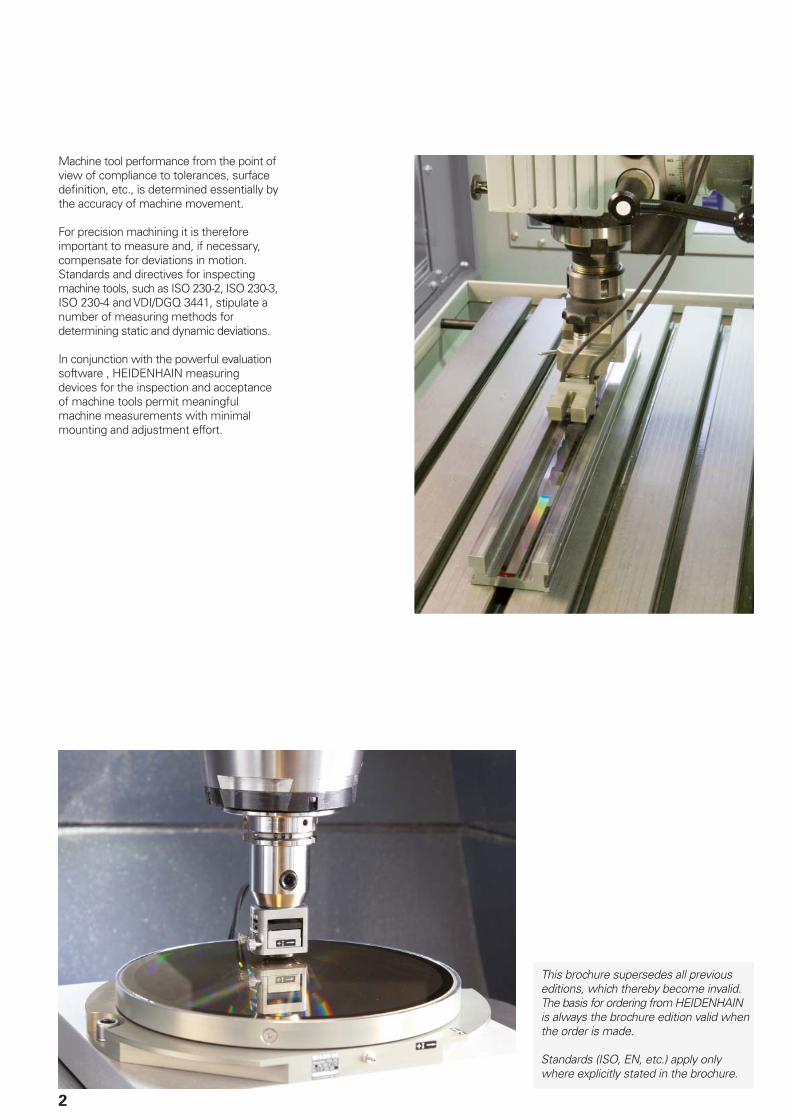
Machine tool performance from the point of view of compliance to tolerances, surface defi nition, etc., is determined essentially by the accuracy of machine movement.
For precision machining it is therefore important to measure and, if necessary, compensate for deviations in motion. Standards and directives for inspecting machine tools, such as ISO 230-2, ISO 230-3, ISO 230-4 and VDI/DGQ 3441, stipulate a number of measuring methods for determining static and dynamic deviations.
In conjunction with the powerful evaluation software , HEIDENHAIN measuring devices for the inspection and acceptance of machine tools permit meaningful machine measurements with minimal mounting and adjustment effort.
This brochure supersedes all previous editions, which thereby become invalid.The basis for ordering from HEIDENHAIN is always the brochure edition valid when the order is made.
Standards (ISO, EN, etc.) apply only where explicitly stated in the brochure.

3
Contents
Introduction
Areas of application 4
Confi guration 5
Measurement procedure
ACCOM evaluation software 6
Dynamically sampled
measurements
• Circular interpolation test• Free-form test• Step response test
6
Static measurement • Positioning accuracy• Guideway error
8
Measurement of the thermal drift 9
Measuring devices for inspection of linear axes
KGM 181
KGM 182
KGM 281
KGM 282
Grid encoders for• Short linear movements• Circular movements• Free-form tests
10
VM 182 Comparator measuring device for• Linear axes• Guideway errors
12
Measuring devices for inspection of rotary axes
General information Fundamentals and mounting instructions 14
Angle encoders ROD 880, RON 886, RPN 886, RON 905 overview 15
Accessories
EIB 74x External Interface Box 16
Adapter cables 17

4
Introduction
Areas of application
The acceptance testing and inspection of machine tools essentially includes the static verifi cation of the geometrical machine structure in the unloaded state and—for NC-controlled machines—on the verifi cation of positioning accuracy. The fi nal results of machining are increasingly infl uenced by dynamic deviations from the nominal contour and by high acceleration rates in the machine tool. Test workpieces are therefore produced and inspected for dimensional accuracy in order to draw conclusions about the dynamic behavior of the machine.
HEIDENHAIN offers measuring devices for direct capture of dynamic and static deviations. The advantage of this direct inspection method over inspecting only the results of the machining lies in its separation of technological infl uences from machine infl uences, and in its capability of distinguishing individual factors of infl uence.
Dynamic measurements—particularly at high traverse speeds—provide information on contouring behavior from which conclusions can be drawn about both the condition of the machine tool as well as the parameter settings of the control loop consisting of the CNC control, drives, and position feedback systems. This information (e.g., kv factor, reversing spikes) can be used to optimize the machine's behavior.
Static measurements, such as the measurement of position error in linear and rotary axes using a comparator system, permit conclusions about the geometric accuracy and thermal behavior of the machine.
Circular interpolation tests with very small radii and free-form tests provide information on the dynamic behavior of the control, and circular interpolation tests with large radii provide information on the machine geometry.
Position accuracy and repeatability, as well as guideway errors of linear machine axes, are determined with a comparator system.
The position accuracy and repeatability of rotary axes, rotary tables and tilting tables can also be determined. A very precise angle encoder serves as comparator system.
Machine tool builders use the results of machine measurements to develop design measures for improving accuracy. Such measurements also help them to optimize the commissioning parameters of the control loop wherever they infl uence the accuracy of a CNC machine.
Machine-tool users can use the measuring devices for acceptance testing and regular accuracy inspection of their machine.

5
A typical setup for inspecting a machine tool consists of the following components:• Measuring device for the inspection of
axis movements (KGM, VM or angle encoder)
• EIB 74x External Interface Box• PC with ACCOM evaluation software
The measuring devices for inspection of linear axes—KGM 181, KGM 182, KGM 281 or KGM 282 grid encoder and the VM 182 comparator system—measure the actual path of traverse without contact and highly dynamically. Both measuring devices permit highly accurate, real 2-D measurement.
Angle encoders are used to measure rotary axes. They are attached to the rotary table or tilting axis, and are connected to the stationary machine element via a measuring bridge.
Since the inspection setup operates completely independently, no communi-cation is necessary between the PC and the CNC. Machines with any type of control can be inspected. The ACCOM evaluation software simply needs to be used to program the same traverse motions on the CNC and on the PC.
ACCOM offers the possibilities of importing NC programs as well as exporting the test NC programs created with ACCOM. This reduces programming efforts, since, for example, freeform contours can simply and quickly be loaded from existing NC programs. HEIDENHAIN plain-language programs can easily be exchanged directly between a TNC control from HEIDENHAIN and the PC. DIN/ISO programs in simplifi ed G-code format can also be imported by ACCOM.
ACCOM automatically detects the beginning of the inspection procedure—for example when a certain distance or angle has been moved from the starting position.
Measuring points are also recorded automatically whenever predefi ned conditions have been fulfi lled (position window, speed window).
The measured data is processed by ACCOM, and then displayed in a clearly understandable manner. The data can also be loaded by other programs (e.g. Matlab, Origin, Excel, etc.), since they are saved in ASCII format.
Confi guration
CNC
NC program
Test program
PC
ACCOM
Test program

6
Measurement procedure
ACCOM evaluation software
Circular interpolation test
In the circular interpolation test, the CNC control performs a circular interpolation in the working plane.
The ACCOM evaluation software compares the values measured by the grid encoder with the ideal (programmed) circular path, and shows the deviations enlarged on the PC screen. ACCOM also calculates the numerical values, such as circular error, circular backlash and radial error, according to DIN ISO 230-4.
The data measured with the circular interpolation tests permit conclusions about the causes of the errors:• Orthogonality errors of the machine axes• Reversal spikes during quadrant
transitions• Hysteresis, reversal error• Incorrect error compensation values in
the control• Errors resulting from irregular thermal
expansion of machine components• Tilt and sag in the machine axes• Axis adjustments• Infl uences of traversing speeds• Infl uence of acceleration
Circular interpolation tests performed over large radii provide information on the machine geometry. On the other hand, circular interpolation tests with small radii provide information on the accuracy of the control under high axis acceleration rates. At small radii, the infl uence of the machine geometry on the result of measurement is insignifi cant. The control and drives, however, have a strong effect.
Circular interpolation tests are performed with the KGM 181, KGM 182, KGM 281
or KGM 282 grid encoders.
The line graph shows a magnifi ed view of the reversal peaks at 90°
Standardized representation of a circular interpolation test with a KGM:The reversal peaks at the quadrant transitions are visible, as is the difference between clockwise and counterclockwise traverse
The measurement methods for inspection and acceptance testing of machine tools are governed by national and international standards and directives. The ACCOM evaluation software for PCs from HEIDEN-HAIN is an easy-to-use program for measured value acquisition and evaluation
Dynamic measurements
according to the DIN ISO 230-2, ISO 230-3, DIN ISO 230-4 and ISO 10791-6 (K2 and K3) standards, as well as the VDI/DGQ directive 3441. The ACCOM evaluation software runs on all PCs with Windows Vista (32-bit), 7, 8 and 10 (32/64-bit).

7
Free-form test
In the free-form test, the CNC moves the machine axes in a plane on any programmed path. The KGM is used to measure the path actually traversed. ACCOM displays the errors in various views. The dynamic behavior of the machine can be evaluated at corners and transitions in the contour. Free-form paths as per ISO 10791—K2 feed rates and K3 interpolation of two axes—can be inspected.
Free-form interpolation tests are performed with the KGM 181, KGM 182, KGM 281
or KGM 282 grid encoders.
The free form shown features some interesting contour transitions:• Continuous transition from line to arc• Continuous transition from arc to line• Abrupt transition from line to arc• Abrupt transition from arc to line• Abrupt transition from line to line
Other typical free-form tests can be performed with the KGM to detect the following errors or effects of the control or mechanics, for example:• Orthogonality of two axes (large cross)• Natural vibration (slanted lines at
approx. 45°, corners)• Path interpolation of two axes (slanted
lines at small angles)
Standardized representation of a free-form test with a KGM and detail zoom: here a normal view shows an overshoot with the resulting rounding-off error. (Nominal path in black, actual path in red)
Result of a step response test as an “Xt” graph
Result of a free-form test with excessive errors
Step response test
The step response test can be used to measure the smallest possible positioning increment (step-response function) and provide information on the infl uence of static friction and the accuracy with which positions can be held. This test is also intended for high-precision tasks requiring increments of as small as 0.1 µm to 0.01 µm. ACCOM permits graphical representation of distance over time (Xt, Yt) and of speed over time (vt).
The step response test can be performed with KGM 181, KGM 182, KGM 281 or KGM 282 grid encoders as well as with the VM 182 comparator system.

8
The positioning accuracy and repeatability of a machine tool is measured after the machine axis has been moved to certain positions.
Determining the static positioning
accuracy of linear axes
The VM and KGM can be used to determine the positioning accuracy of a machine tool when moving machine axes to specifi ed positions. Besides the positioning accuracy, these devices can also measure the guideway error perpendicular to the direction of the machine tool’s slide.
ACCOM displays the errors clearly according to the respective standards.
Small traverse paths up to 230 mm can be measured with KGM 181, KGM 182, KGM 281 or KGM 282 grid encoders, larger traverse paths up to 1520 mm can be measured with the VM 182 comparator system.
Determining the static positioning
accuracy of rotary axes
By using an angle encoder as reference, any angular positions can be traversed to, and a detailed graph of the accuracy can be recorded.
The high-precision ROD, RON or RPN angle encoders from HEIDENHAIN are used to determine the positioning accuracy of rotary encoders.
ACCOM evaluates the measurement and displays the results clearly.
The example shows the graphs of two high-resolution measurements of a rotary table with a worm gear. The fi gure above illustrates position feedback via the rotary encoder in the motor (Semi-Closed Loop). It shows the errors caused by the worm shaft (short-wave oscillations) and the worm wheel (long-wave oscillations) of the rotary table. The measurement of the same rotary table but with an angle encoder integrated for position capture (Closed Loop) shows a much smaller range of error.
Measurement of the static positioning accuracy as per DIN ISO 230-2 and the guideway error in transverse direction with the VM 182
Measurement of the static positioning accuracy of a rotary table with worm gear with the RON 905 and feedback via the rotary encoder in the motor (Semi-Closed Loop) ...
Measurement procedure
Static measurements
... and for feedback from an angle encoder (Closed Loop)

9
Determining the thermal behavior of a linear axis as per ISO 230-3 measurement with the VM 182 and feedback via the rotary encoder on the motor (“Semi-Closed Loop”) ...
Determining the thermal behavior of
feed axes
The infl uence of frictional heat in ball screws of linear axes or worm gears of rotary axes on the position behavior of the feed axis becomes obvious when positioning tests are performed as per the ISO 230-3 standard.
This standard contains recommendations for making uniform measurements of thermal shifts of lathes and milling machines as a result of external and internal heat sources.
To test the feed axes, it proposes a repeated positioning to two points that lie as near as possible to the ends of the traverse range at an agreed percentage of the rapid traverse velocity. The change of the positions with respect to the initial value is recorded. The test is to be conducted until a satiation effect is clearly observable.
The example shows the graphs of two measurements on a linear axis. The upper graph, with a rotary encoder in the motor for position capture, shows increasing position errors over time due to heating of the ball screw. The same measurement of the linear axis, but with a linear encoder for position capture, is shown below. The position errors are independent of the heating of the ball screw, since the linear encoder always captures the actual position of the axis slide.
The thermal behavior of linear axes is measured with KGM 181, KGM 182, KGM 281 or KGM 282 encoders, or—for longer traverse paths—with the VM 182. The ROD, RON or RPN angle encoders are used for rotary axes.
... and for feedback from an angle encoder (Closed Loop)
Measurement of the thermal drift
For more information:
You will fi nd more information on this topic in the following Technical Information documents: • Accuracy of Feed Axes• Linear Encoders Improve Machining
Accuracy

10
Measuring devices for inspection of linear axes
KGM 181, KGM 182, KGM 281, KGM 282 – grid encoders
The KGM grid encoders consist of a grid plate with a waffl e-type graduation, which is embedded in a mounting base, and a scanning head. During measurement, the scanning head moves over the grid plate without making mechanical contact. The KGM encoders capture any motions in a plane and separately transmit the values measured for the two axes.
Area of application
The KGM encoders dynamically test the contouring accuracy of controlled machine tools. For example, they make circular
interpolation tests possible with radii ranging from 115 mm down to 0.1 mm at feed rates up to 80 m/min. Especially at very small radii, the errors resulting from the machine’s geometry no longer have an infl uence on the measurement results.
The contact-free scanning also permits free-form tests over any contours in two axes.
Measuring setup
For setup, the mounting base is fi xed onto the workpiece-holding element (such as the machining table) and aligned to the axes. The scanning head is mounted on the tool-holding element (for example, the spindle of a machining center) so that it cannot rotate and is also approximately aligned to the axes.
An adjustment plate is included in delivery for simple adjustment of the scanning gap to 0.5 ±0.05 mm. The setting screws of the scanning head are then used for the fi ne adjustment. They are used to optimize the measurement signals displayed in the ACCOM evaluation software.
Items supplied:
• KGM 181, KGM 182, KGM 281 or KGM 282
• Adapter for mounting the scanning head at an angle of 90° (for 20 mm mating )
• Mounting kit for XZ/YZ plane (only for KGM 181 and KGM 281)
Accessories:
• EIB 74x External Interface Box• ACCOM evaluation software• Two adapter cables between KGM and
EIB 74x• Mounting kit for XZ/YZ plane for KGM 182
and KGM 282
KGM 181 KGM 182 KGM 281 KGM 282
Measuring standard
Coeffi cient of linear expansionTwo-coordinate TITANID phase gratingtherm 8 x 10⁻⁶ K–1
Accuracy grade ±2 µm ±1 µm
Measuring range 140 mm 230 mm 140 mm 230 mm
Incremental signals 1 VPP
Signal period 4 µm in measuring directions I and II
Measuring step 0.001 µm (with EIB 74x)
Voltage supply 5 V ±0.25 V/< 100 mA (per axis)
Mount for scanning head 20h7
Traversing speed 80 m/min 72 m/min
Mass Grid plateScanning head
4.0 kg 0.6 kg
3.1 kg 0.6 kg
2.3 kg 0.6 kg
4.9 kg 0.6 kg
Grid
Mounting adapter
Scanning head
Direction of measurement

KGM 181
L
B
D1
D2
328 228
160 260
228
160
328
262
KGM 282KGM 281KGM 182
204
180
304
280
204
180
304
280
11
I, II = Directions of measurementF = Machine guideway* = Max. change during operation1 = Hose connection nipple for vacuum connection (for fastening on plane surfaces/stone plates)2 = Adjusted during mounting

12
Linear scale Scanning head with auxiliary carriage
Grid
Reference mark
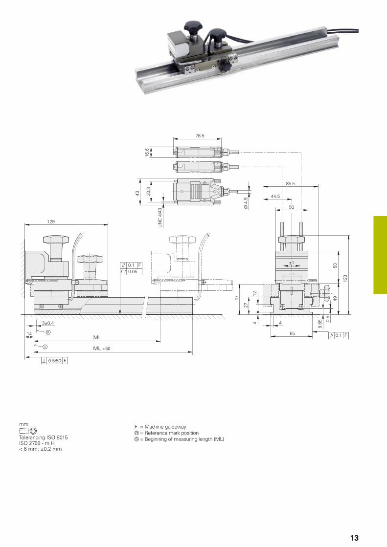
The VM 182 comparator system incorporates a scale with a very precise two-coordinate phase grating and a scanning head that moves over the grating without mechanical contact. The scale is embedded in a massive, U-shaped steel profi le, and can therefore be mounted directly on the machine table. Along with the measuring position in longitudinal direction, the VM 182 also captures small errors (±1 mm) perpendicular to the direction of measurement.
Area of application
The VM 182 serves for acceptance testing, inspection and calibration of machine tools and measuring equipment with traverse ranges up to 1520 mm. Machine tool builders and distributors can use the VM 182 to determine the linear and nonlinear error curves as well as the reversal error of machine axes according to DIN ISO 230-2. Along with the position error, it also meas-ures the guideway error orthogonal to the traverse direction of the machine axis.
Measuring setup
During mounting, the scanning head is connected to the scale by an auxiliary carriage. The scale is clamped paraxially onto the machine table and the scanning head is connected to the machine spindle with a coupling magnet. After mounting is completed, the auxiliary carriage is removed from the scanning head. The generous mounting tolerances simplify installation of the VM 182.
Items supplied:
• VM 182
Accessories:
• Bracket for attaching the scanning head to the machine spindle
• EIB 74x External Interface Box• ACCOM evaluation software• Two adapter cables between VM and
EIB 74x
Measuring devices for inspection of linear axes
VM 182 – comparator system
VM 182
Measuring standard
Coeffi cient of linear expansionTwo-coordinate DIADUR phase gratingtherm 10 x 10–6 K–1
Accuracy grade ±1 µm in longitudinal direction±1.5 µm in transverse direction
Measuring length ML
Linear direction in mm 420 520 720 1020 1220 1520
Measuring range
transverse direction±1 mm
Reference mark One reference mark at beginning of measuring length
Incremental signals 1 VPP
Signal period 4 µm in longitudinal and transverse direction
Measuring step 0.001 µm (with EIB 74x)
Voltage supply 5 V ±5 %/< 100 mA (per axis)
Coupling Magnetically to a plane surface; bracket available as accessory
Traversing speed 80 m/min
Mass Linear scaleScanning head
340 g + 6.7 g/mm ML 1.86 kg
13
F = Machine guidewayR = Reference mark positionS = Beginning of measuring length (ML)

a
b
14
Measurement of rotary axes
General information
Areas of application
The position errors of rotary axes (rotary or tilting tables, swivel heads) are often decisive factors in a machine’s overall accuracy.
At this time, rotary and tilting axes are not involved as simultaneously moving axes in most cases. The positioning accuracy, as per ISO 230-2 for example, is defi nitive for such index axes. In addition, the dynamic and thermal behavior according to ISO 230-3 is important for the increasing number of simultaneously moving axes.
Measuring setup
Due to the different possibilities for mounting on the machine (rotary and tilting axes, various diameters of rotary tables, etc.), the customer must install the reference angle encoder himself.
A stiff connection between the stator and rotor of the reference encoder must be ensured. Since a certain amount of torque is needed in order for the reference encoder to move, the measuring accuracy will be affected if the connection is not rigid enough.
A connecting element with length L and diameter D between the shaft of the reference encoder and the stationary part of the measuring setup becomes twisted as shown in the graph. Whether the shaft is solid or hollow is of secondary importance.
Angle encoders from HEIDENHAIN serve as high precision reference encoders for the measurement of rotary axes. They permit measurements at any positions. Since no restrictions are necessary, such as to only 12 positions per 360°, even short-range position errors can be measured.
In addition, angle encoders make highly dynamic motions of the rotary table between the points of measurement possible (as per ISO 230-3).
Torsion error of the 100-mm long coupling of an ROD 880 via aa) Solid shaft with various diameters D1b) Hollow shaft with outside diameter D1 = 25 mm and various inside
diameters D2
Diameter [mm]
Tors
ion
err
or
[”]
Radius [mm]
Po
sit
ion
err
or
[µm
]
Infl uence of the distance R of the machining position from the center of the rotary table on the positioning accuracy ∆x at various angular errors ∆ of the rotary table
Reference angle encoder

ROD 880 RON 886/RPN 886 RON 905
15
Angle encoders for the measurement of rotary axes
Due to their accuracy and mechanical versions, the angle encoders listed here are especially suited for the measurement of rotary axes. They have integral bearings, but are coupled to the shaft differently:
The shaft of the ROD 880 is connected via a separate shaft coupling to the shaft to be measured. Suitable shaft couplings, such as a K01 diaphragm coupling or K16 and K17 fl at couplings are described in the Angle Encoders with Integral Bearing brochure.
RON 886 and RPN 886 encoders have an integrated stator coupling. The shaft to be measured is directly connected with the hollow through shaft.
The RON 905 also has an integrated stator coupling. The shaft to be measured is directly connected with the blind hollow shaft.
ROD 880 RON 886 RPN 886 RON 905
System accuracy ±1” ± 0.4”
Incremental signals 1 VPP 11 µAPP
Line count 36 000 90 000 ( 180 000 signal periods)
36 000
Measuring step
With EIB 74x0.000 005° 0.0000005° 0.000 005°
Shaft Solid shaft D = 14 mm Hollow through shaft D = 60 mm Blind hollow shaft
Starting torque 0.012 Nm at 20 °C 0.5 Nm at 20 °C 0.005 Nm at 20 °C
Shaft load Axial Radial
30 Nm;30 Nm at shaft end
– –
Mass 2.0 kg 2.5 kg 4.0 kg
For more information:
Brochure: Angle Encoders with Integral Bearing
16
Accessories
EIB series – External Interface Box
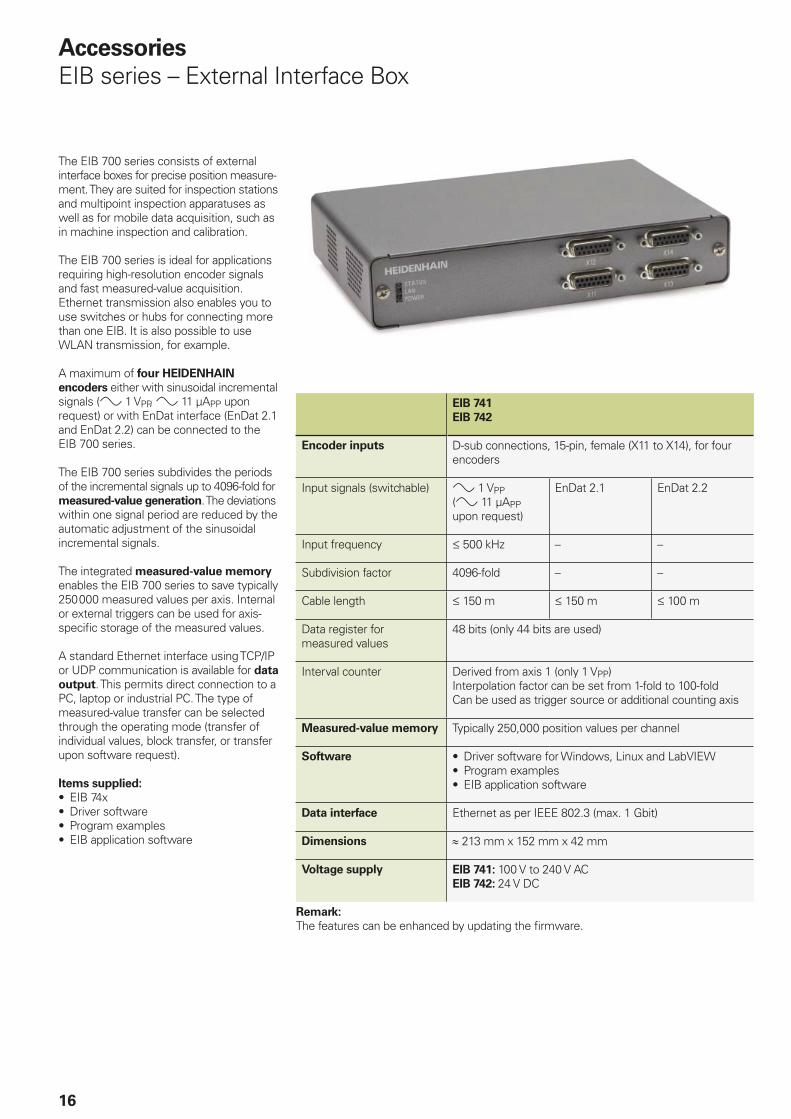
The EIB 700 series consists of external interface boxes for precise position measure-ment. They are suited for inspection stations and multipoint inspection apparatuses as well as for mobile data acquisition, such as in machine inspection and calibration.
The EIB 700 series is ideal for applications requiring high-resolution encoder signals and fast measured-value acquisition. Ethernet transmission also enables you to use switches or hubs for connecting more than one EIB. It is also possible to use WLAN transmission, for example.
A maximum of four HEIDENHAIN
encoders either with sinusoidal incremental signals ( 1 VPP, 11 µAPP upon request) or with EnDat interface (EnDat 2.1 and EnDat 2.2) can be connected to the EIB 700 series.
The EIB 700 series subdivides the periods of the incremental signals up to 4096-fold for measured-value generation. The deviations within one signal period are reduced by the automatic adjustment of the sinusoidal incremental signals.
The integrated measured-value memory enables the EIB 700 series to save typically 250 000 measured values per axis. Internal or external triggers can be used for axis-specifi c storage of the measured values.
A standard Ethernet interface using TCP/IP or UDP communication is available for data
output. This permits direct connection to a PC, laptop or industrial PC. The type of measured-value transfer can be selected through the operating mode (transfer of individual values, block transfer, or transfer upon software request).
Items supplied:
• EIB 74x• Driver software• Program examples• EIB application software
EIB 741
EIB 742
Encoder inputs D-sub connections, 15-pin, female (X11 to X14), for four encoders
Input signals (switchable) 1 VPP ( 11 µAPP upon request)
EnDat 2.1 EnDat 2.2
Input frequency 500 kHz – –
Subdivision factor 4096-fold – –
Cable length 150 m 150 m 100 m
Data register for measured values
48 bits (only 44 bits are used)
Interval counter Derived from axis 1 (only 1 VPP)Interpolation factor can be set from 1-fold to 100-foldCan be used as trigger source or additional counting axis
Measured-value memory Typically 250,000 position values per channel
Software • Driver software for Windows, Linux and LabVIEW• Program examples• EIB application software
Data interface Ethernet as per IEEE 802.3 (max. 1 Gbit)
Dimensions 213 mm x 152 mm x 42 mm
Voltage supply EIB 741: 100 V to 240 V ACEIB 742: 24 V DC
Remark:
The features can be enhanced by updating the fi rmware.

17
Adapter cable
The cables necessary for connecting the encoders to the EIB 74x subsequent electronics are available as accessories. The maximum cable length of 10 m should not be exceeded.

18
Application examples
Free-form test with KGM 182
Determining the positioning accuracy with a VM 182
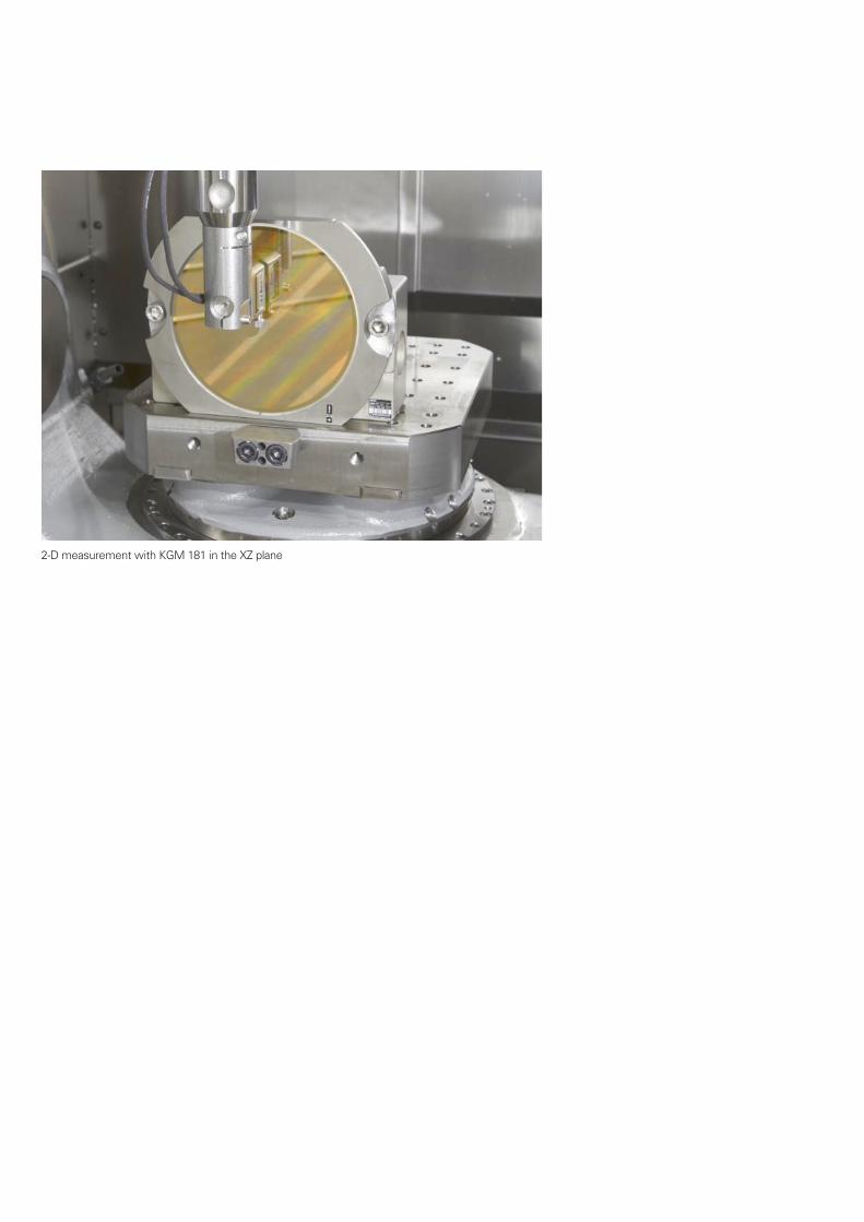
2-D measurement with KGM 181 in the XZ plane

PH MACHINEBANKS' CORPORATIONQuezon City, Philippines 1113E-mail: [email protected]
PL APS02-384 Warszawa, Polandwww.heidenhain.pl
PT FARRESA ELECTRÓNICA, LDA.4470 - 177 Maia, Portugalwww.farresa.pt
RO HEIDENHAIN Reprezentanta RomaniaBrasov, 500407, Romaniawww.heidenhain.ro
RS Serbia BG
RU OOO HEIDENHAIN115172 Moscow, Russiawww.heidenhain.ru
SE HEIDENHAIN Scandinavia AB12739 Skärholmen, Swedenwww.heidenhain.se
SG HEIDENHAIN PACIFIC PTE LTDSingapore 408593www.heidenhain.com.sg
SK KOPRETINA TN s.r.o.91101 Trencin, Slovakiawww.kopretina.sk
SL NAVO d.o.o.2000 Maribor, Sloveniawww.heidenhain.si
TH HEIDENHAIN (THAILAND) LTDBangkok 10250, Thailandwww.heidenhain.co.th
TR T&M Mühendislik San. ve Tic. LTD. STI·.
34775 Y. Dudullu – Ümraniye-Istanbul, Turkeywww.heidenhain.com.tr
TW HEIDENHAIN Co., Ltd.Taichung 40768, Taiwan R.O.C.www.heidenhain.com.tw
UA Gertner Service GmbH Büro Kiev 02094 Kiev, Ukrainewww.heidenhain.ua
US HEIDENHAIN CORPORATIONSchaumburg, IL 60173-5337, USAwww.heidenhain.com
VE Maquinaria Diekmann S.A. Caracas, 1040-A, VenezuelaE-mail: [email protected]
VN AMS Co. LtdHCM City, VietnamE-mail: [email protected]
ZA MAFEMA SALES SERVICES C.C.Midrand 1685, South Africawww.heidenhain.co.za
ES FARRESA ELECTRONICA S.A.08028 Barcelona, Spainwww.farresa.es
FI HEIDENHAIN Scandinavia AB01740 Vantaa, Finlandwww.heidenhain.fi
FR HEIDENHAIN FRANCE sarl92310 Sèvres, Francewww.heidenhain.fr
GB HEIDENHAIN (G.B.) LimitedBurgess Hill RH15 9RD, United Kingdomwww.heidenhain.co.uk
GR MB Milionis Vassilis17341 Athens, Greecewww.heidenhain.gr
HK HEIDENHAIN LTDKowloon, Hong KongE-mail: [email protected]
HR Croatia SL
HU HEIDENHAIN Kereskedelmi Képviselet1239 Budapest, Hungarywww.heidenhain.hu
ID PT Servitama Era ToolsindoJakarta 13930, IndonesiaE-mail: [email protected]
IL NEUMO VARGUS MARKETING LTD.Holon, 58859, IsraelE-mail: [email protected]
IN HEIDENHAIN Optics & ElectronicsIndia Private LimitedChetpet, Chennai 600 031, Indiawww.heidenhain.in
IT HEIDENHAIN ITALIANA S.r.l.20128 Milano, Italywww.heidenhain.it
JP HEIDENHAIN K.K.Tokyo 102-0083, Japanwww.heidenhain.co.jp
KR HEIDENHAIN Korea LTD.Gasan-Dong, Seoul, Korea 153-782www.heidenhain.co.kr
MX HEIDENHAIN CORPORATION MEXICO20290 Aguascalientes, AGS., MexicoE-mail: [email protected]
MY ISOSERVE SDN. BHD.43200 Balakong, SelangorE-mail: [email protected]
NL HEIDENHAIN NEDERLAND B.V.6716 BM Ede, Netherlandswww.heidenhain.nl
NO HEIDENHAIN Scandinavia AB7300 Orkanger, Norwaywww.heidenhain.no
NZ Llama ENGINEERING Ltd5012 Wellington, New ZealandE-mail: [email protected]
AR NAKASE SRL.B1653AOX Villa Ballester, Argentinawww.heidenhain.com.ar
AT HEIDENHAIN Techn. Büro Österreich83301 Traunreut, Germanywww.heidenhain.de
AU FCR MOTION TECHNOLOGY PTY LTDLaverton North Victoria 3026, AustraliaE-mail: [email protected]
BE HEIDENHAIN NV/SA1760 Roosdaal, Belgiumwww.heidenhain.be
BG ESD Bulgaria Ltd.Sofi a 1172, Bulgariawww.esd.bg
BR HEIDENHAIN Brasil Ltda.04763-070 – São Paulo – SP, Brazilwww.heidenhain.com.br
BY GERTNER Service GmbH220026 Minsk, Belaruswww.heidenhain.by
CA HEIDENHAIN CORPORATIONMississauga, OntarioL5T2N2, Canadawww.heidenhain.com
CH HEIDENHAIN (SCHWEIZ) AG8603 Schwerzenbach, Switzerlandwww.heidenhain.ch
CN DR. JOHANNES HEIDENHAIN (CHINA) Co., Ltd.Beijing 101312, Chinawww.heidenhain.com.cn
CZ HEIDENHAIN s.r.o.102 00 Praha 10, Czech Republicwww.heidenhain.cz
DK TP TEKNIK A/S2670 Greve, Denmarkwww.tp-gruppen.dk
DE HEIDENHAIN Vertrieb Deutschland83301 Traunreut, Deutschland 08669 31-3132 08669 32-3132E-Mail: [email protected]
HEIDENHAIN Technisches Büro Nord12681 Berlin, Deutschland 030 54705-240
HEIDENHAIN Technisches Büro Mitte07751 Jena, Deutschland 03641 4728-250
HEIDENHAIN Technisches Büro West44379 Dortmund, Deutschland 0231 618083-0
HEIDENHAIN Technisches Büro Südwest70771 Leinfelden-Echterdingen, Deutschland 0711 993395-0
HEIDENHAIN Technisches Büro Südost83301 Traunreut, Deutschland 08669 31-1345
Vollständige und weitere Adressen siehe www.heidenhain.deFor complete and further addresses see www.heidenhain.de
������������ ��� ��������������� ��������������������������������������� �������������� �������������������� !��"�#����������
������ !���� ��!�
208871-29 · 5 · 05/2018 · H · Printed in Germany