the kenya power and lightin g company … for scada system … · list of tables v list of diagram...
TRANSCRIPT

DeSCAD
THE KEN
esign, SDA Syst
P
NYA POW
SCA
BIDD
upply antem for D
Telec
Part 2
WER AND
DA SYS
DING DO
Cont
nd InstaDistribucommun
VO
Octo
Employe
i
D LIGHTIN
STEM EX
OCUME
tract A3
allation ation Subnication
LUME 2
ober 201
er’s Requi
NG COMP
XTENSIO
NTS FO
37:
and Combstationns Syste
2
14
irements
PANY LIM
ON
OR
mmissions and Aem
MITED
oning of Associatted

ii
TABLE OF CONTENTS
TABLE OF CONTENTS ii
LIST OF TABLES v
LIST OF DIAGRAM vi
ACRONYMS vii
CHAPTER ONE 1
1 General Project Information and scope 1
1.1 Project Scope 1
1.2 Project Area 6
1.3 General information on Technical Requirements 6
1.3.1 Work on Live Substations 6
1.3.2 Installation 7
1.3.3 Testing and commissioning 7
1.3.4 On the Job Training 8
1.4 Control, Monitoring and Telecommunication Equipment 8
1.4.1 General 8
1.4.2 Control panels, cubicles and racks 10
1.4.3 Power supplies and fusing 13
1.4.4 Indicators 15
1.4.5 Electronic equipment 16
1.4.6 Switches and relays 16
1.4.7 Measurement of electrical parameters 17
1.4.8 Wiring, cabling terminals 17
1.4.9 Labeling 17
1.4.10 Painting 18
1.5 Documentation and Drawings 19
1.5.2 Bid Drawings 20
1.5.3 Progress Plans 21
1.5.4 Exchange of Interface Information 21

iii
1.5.5 Final Documentation 22
CHAPTER TWO 23
2 RTUs & ADAPTATION WORKS OF SUBSTATION 23
2.1 Existing data acquisition system 23
2.1.1 Existing Teleinformation Plan 24
2.1.2 New RTUs 26
2.1.3 New Remote Terminal Units (RTUs) and Adaptation Works at Substations 35
2.1.4 Guaranteed Technical Particulars 58
2.2 Integration of the new stations to the SCADA/EMS system 63
2.2.1 General Information 63
2.2.2 Data Population 63
2.2.3 RTU and SCADA tests 64
2.3 TRAINING 65
CHAPTER THREE 66
3 TELECOMMUNICATIONS 66
3.1 FIBER OPTIC LINKS 66
3.1.1 GENERAL 66
3.1.2 FIBER OPTIC CABLE SPECIFICATIONS 69
3.1.3 FIBER OPTIC TOOLS & TEST EQUIPMENT SPECIFICATIONS 82
3.1.4 THE FIBER OPTIC TERMINAL EQUIPMENT SPECIFICATIONS 87
3.1.5 THE FIBER OPTIC CABLE & TERMINAL EQUIPMENT SPARES REQUIREMENT 97
3.1.6 TESTING 97
3.1.7 TRAINING 98
3.2 RADIOS 98
3.2.1 THE TECHNICAL SPECIFICATIONS 98
3.2.2 NEW INSTALLATIONS 101
3.2.3 COMMUNICATION TOWERS 103
CHAPTER FOUR 108
4 48 VDC CHARGERS AND BATTERIES 108

iv
4.1 GENERAL REQUIREMENTS 108
4.2 DETAILED TECHNICAL SPECIFICATIONS 109
4.2.1 GENERAL REMARKS 109
4.2.2 SCOPE 109
4.2.3 RECTIFIER/ BATTERY CHARGER 109
4.2.4 BATTERY 118
4.2.5 D.C. CONTROL AND DISTRIBUTION BOARD 122
4.2.6 METERING AND MONITORING SYSTEM 123
4.2.7 ENCLOSURE 126
4.2.8 MANUALS, DRAWINGS AND MAINTENANCE SOFTWARE 127
4.2.9 SPARE PARTS 128
4.2.10 WARRANTY 128
4.2.11 TRAINING 128
4.2.12 TESTS 128
4.2.13 APPLICABLE STANDARDS 132
4.2.14 SCHEDULES 134

v
LIST OF TABLES
Table 1‐1 Summary of scope ......................................................................................................................... 3
Table 2‐1 Distribution of monitored stations ............................................................................................. 23
Table 2‐2 Type of alarms per bay in substations ........................................................................................ 30
Table 2‐3 Number of alarms per voltage levels .......................................................................................... 32
Table 2‐5: Existing RTUs in the scope ......................................................................................................... 37
Table 2‐6 Guaranteed Techinical Particulars .............................................................................................. 58
Table 3‐1 Estimated Distances .................................................................................................................... 71
Table 3‐2 Distribution of ODF’s ................................................................................................................... 75
Table 3‐3 ..................................................................................................................................................... 77
Table 3‐4General Specifications for ODF .................................................................................................... 79
Table 3‐5 ..................................................................................................................................................... 80
Table 3‐6 Technical Specifications for Splicing Machine ............................................................................ 83
Table 3‐7 Minimum requirements for Fault Locator .................................................................................. 85
Table 3‐8 Proposed Link Equipment ........................................................................................................... 87
Table 3‐9 Guaranteed technical particulars (multiplexer) .......................................................................... 91
Table 3‐10 Guaranteed technical particulars (Switch) ................................................................................ 93
Table 3‐11 ................................................................................................................................................... 96
Table 3‐12 ................................................................................................................................................... 97
Table 3‐13 Radio Details ........................................................................................................................... 101
Table 3‐14 Link Details .............................................................................................................................. 102
Table 3‐15 ................................................................................................................................................. 106
Table 4‐1 Guaranteed Technical Specifications ........................................................................................ 134
Table 4‐2List of 48V Battery Chargers ...................................................................................................... 149

vi
LIST OF DIAGRAM
Figure 3‐1 SCADA, DATA & Telephony Integration ..................................................................................... 90
Figure 4‐1 Fig. 4.2.3.9.1: ............................................................................................................................ 115
Figure 4‐2 .................................................................................................................................................. 116

vii
ACRONYMS
SCADA/EMS – Supervisory Control and Data acquisition/Energy Management system
KPLC - Kenya power and Lighting Co. Ltd.
RTU – Remote terminal unit
SAS – Substation automation system

1
CHAPTER ONE
1 General Project Information and scope
1.1 Project Scope
This Part of the Specification describes the SCADA and Telecommunication System to be
supplied to the Kenya power and Lighting Co. Ltd. (KPLC) for distribution and selected
transmission stations. Each bidder is encouraged to propose its standard system to the extent
possible, as long as it meets or exceeds the requirements of this Specification.
New and existing RTUs including all necessary interfacing to the substation equipment are to be
installed or extended at 58 selected Substations of the Kenya Power and Lighting Co. Ltd.
(KPLC). The existing RTUs need to be expanded to cater for additional data requirement from
the sub-stations. The details are captured in chapter 2 of this specification.
The Telecommunication system to be supplied under this contract shall satisfy KPLC's
communication requirements for operational purposes that is; operational telephony and SCADA
/ EMS data transmission. The telecommunication system to be provided shall consist of fibre
optic and radio links together with all telephone and data transmission equipment required as
described in Chapter 3 of this Specification. The power supply for both SCADA and
Telecommunications equipment is also captured in chapter 4 of this specification.
The Project covers the design, manufacture, testing, supply, insurance, packing for export,
shipment, delivery to site, unloading, complete erection, testing on completion, commissioning
for the SCADA and Telecommunication Systems for the distribution stations.
In particular the project comprises:
(i) installation of all equipment and works necessary to interface the controls,
indications, alarms, measurement and metering data from the substations to the
SCADA / EMS system.

2
(ii) Integration of all the station RTUs to the existing KPLC’s central SCADA/EMS
system
(iii) Establishment of telecommunication network for transmission of SCADA data and
speech using fibre optic and UHF / VHF radio communication links.
(iv) Installation of a complete 48V dc power supply system that serves both SCADA and
communication systems per station.
(v) Training on SCADA equipment, telecommunications equipment’s.
(vi) Provision of Spares, Tools & Test Equipment, As built documentation and other
facilities for project management as described in the detailed specifications.
1.2 Project Timelines
The project is expected to be completed in 18 months from inception. In order to maximize on the project benefits, all the Substations in all Lots, where the whose SAS/RTU have been installed and locally tested under other projects and communication media, namely fibre has already been installed, necessary Multiplexers/Switch shall be commissioned within Six (6) months of contract effectiveness.
1.3 Project LOTs
The project is divided into three lots namely:
1. LOT 1:Design, Supply and Installation and Commissioning of SCADA System for Distribution Substations and Associated Telecommunications System for Nairobi and Mt. Kenya Regions
2. LOT 2: Design, Supply and Installation and Commissioning of SCADA System for Distribution Substations and Associated Telecommunications System, for Coast Region.
3. LOT 3:Design, Supply and Installation and Commissioning of SCADA System for Distribution Substations and Associated Telecommunications System, for West Kenya Region.

3
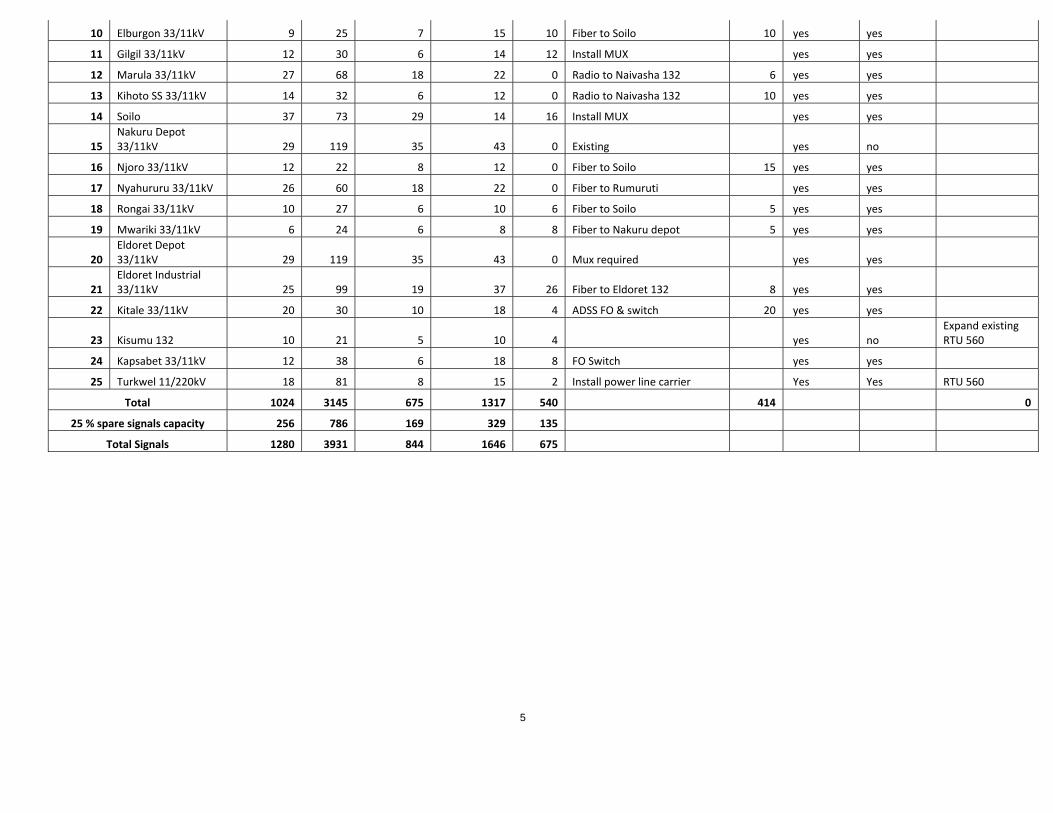
Table 1-1 Summary of scope
Signal list Totals
Region Station Indications Alarms Commands Measurands
Energy Meter Inputs Telecomms solution
ADSS approx Length (km)
Scada Installation
Telecomms Installation
Existing Scada in station
Nairobi LOT 1
1 Doonholm 11kV Fiber to Nairobi South with switches No yes Siemens SAS
2 Industrial 66/11kV 29 107 21 42 36 Fiber to Nairobi South with switches 8 yes yes RTU 560
3 Karen 66/11kV Replace Radio with Mux No yes
4 Kikuyu 66/11kV 26 78 21 43 20 Radio to Ngong Hills yes yes RTU 560
5 Limuru 66/11kV 8 18 4 4 2 Install MUX yes yes Siemens SAS
6 Athi River ss 33/11kV 16 49 8 21 6 Install MUX no yes
7 Machakos 33/11kV 16 49 8 21 6 Intsall FO Switches yes yes
8 Nairobi Airport 66/11kV 30 101 18 43 26
Fiber to Embakasi with switches no yes Siemens SAS
9 Nairobi West 66/11kV 48 174 22 88 40 Fiber to Embakasi available yes yes RTU 560
10 Nyaga 33/11kV 18 28 13 30 2 Fiber to Ruiru with switches 20 yes yes
11 Muthurwa 52 179 31 92 42 Intsall Switches no yes Siemens SAS
12 Steel Billets 24 88 15 25 4 Radio to Juja yes yes
13 EPZ 24 96 12 16 4 Install FO switche yes yes RTU 560
14 Mai Mahiu 24 128 18 24 4 Install MUX 30 Yes Yes
Mount Kenya
1 Embu East Install FO Switches no Yes SAS Exists
2 Embu 33/11 kV 22 83 15 36 20 Install FO switches & FO 25 yes Yes
3 Karatina 33/11 kV 30 69 13 31 16 Fiber to Kiganjo with switches 20 yes Yes
4 Kerugoya 33/11 kV 13 35 6 16 10 Fiber to Karatina with switches 20 yes Yes
5 Nanyuki 33/11 kV 14 42 7 20 10 Fiber to Nanyuki 132 Installed yes Yes
6 Ndarugu 33/11 kV 11 34 5 19 8 Install fibre from Mangu & switches 10 yes Yes

4
7 Meru 33/11 kV 19 65 12 32 16 Install FO switches yes Yes
8 Othaya 33/11 kV 26 65 12 29 14 Fiber to Ruringu with switches yes Yes
9 Githambo 33/11 kV 11 34 5 19 8 Fiber to Githambo 132kV with FO switches 10 yes Yes
10 Kiganjo 33/11 kV 22 61 11 27 12 Radio to Kiganjo 132kV 7 yes Yes Expand Existing RTU 560
LOT 2
Coast
1 Msambweni 12 24 10 13 2 Fiber from Mwambungo 20 yes yes
2 Mwabungo 33/11kV 10 22 9 13 2 Fiber to Galu 132kV 5 yes yes
3 Rabai Bamburi Fibre to Rabai + Mux 35 No yes
4 Kanamai 8 22 8 10 2 Fibre From Bamburi 18 yes yes
5 Watamu 7 22 8 10 2 Fiber to Malindi 132kV 25 yes yes
6 Kaloleni 33/11kV 6 14 7 9 2 ADSS + switches 30 yes yes
7 Malindi 33/11kV Install MUX no yes
8 Utange 33/ 11 kV SS 10 24 9 12 2 Fibre From Bamburi + FO switches 12 yes yes
9 Shanzu 33/ 11 kV SS Fibre From Bamburi ‐ Kanamai line 5 No yes Areva
10 Mbaraki 40 118 24 26 yes no RTU 560
11 Mwatate 33/ 11 kV 10 24 9 12 2 Fibre From Voi + FO switches 20 yes yes
Western Kenya LOT 3
1 Kakamega 33/11kV 20 50 20 24 0 Install MUX yes yes
2 Kericho 33/11kV 23 65 12 32 16 Fiber to Chemosit with Mux 20 yes yes
3 Kisian 33/11kV 16 42 7 25 14 Fiber to Obote road with FO switches 15 yes yes
4 Kisii 33/11kV 27 99 19 43 30 Fiber to Kegati available.need switches yes yes
5 Kisumu East 33/11kV 25 73 14 33 16 Fiber to Kisumu 132 kV with FO switches 10 yes yes
6 Mogogosiek 33/11kV 24 69 13 31 14 Radio to Chemosit yes yes
7 Obote Rd 33/11kV 28 107 21 42 32 Fiber to Kisumu 132 available yes yes
8 Sotik 33/11kV 12 38 6 18 8 Radio to Chemosit yes yes
9 Cheptulu 33/11kv 9 33 8 13 0 Radio to Kakamega 20 yes yes
5
10 Elburgon 33/11kV 9 25 7 15 10 Fiber to Soilo 10 yes yes
11 Gilgil 33/11kV 12 30 6 14 12 Install MUX yes yes
12 Marula 33/11kV 27 68 18 22 0 Radio to Naivasha 132 6 yes yes
13 Kihoto SS 33/11kV 14 32 6 12 0 Radio to Naivasha 132 10 yes yes
14 Soilo 37 73 29 14 16 Install MUX yes yes
15 Nakuru Depot 33/11kV 29 119 35 43 0 Existing yes no
16 Njoro 33/11kV 12 22 8 12 0 Fiber to Soilo 15 yes yes
17 Nyahururu 33/11kV 26 60 18 22 0 Fiber to Rumuruti yes yes
18 Rongai 33/11kV 10 27 6 10 6 Fiber to Soilo 5 yes yes
19 Mwariki 33/11kV 6 24 6 8 8 Fiber to Nakuru depot 5 yes yes
20 Eldoret Depot 33/11kV 29 119 35 43 0 Mux required yes yes
21 Eldoret Industrial 33/11kV 25 99 19 37 26 Fiber to Eldoret 132 8 yes yes
22 Kitale 33/11kV 20 30 10 18 4 ADSS FO & switch 20 yes yes
23 Kisumu 132 10 21 5 10 4 yes no Expand existing RTU 560
24 Kapsabet 33/11kV 12 38 6 18 8 FO Switch yes yes
25 Turkwel 11/220kV 18 81 8 15 2 Install power line carrier Yes Yes RTU 560
Total 1024 3145 675 1317 540 414 0
25 % spare signals capacity 256 786 169 329 135
Total Signals 1280 3931 844 1646 675

6
1.4 Project Area
The KPLC SCADA system is implemented into four main regions of operations. These are
Nairobi, Coast, West Kenya and Mount Kenya regions.
The National Control Centre and the Regional Control Centres host the main SCADA system for
which the RTUs shall be connected to.
The control centres are: National Control Centre (NCC) in Nairobi, West Regional Control
centre (WRCC) at Lessos, Coast Regional Control Centre ( CRCC) at Rabai, Mt. Kenya
Regional Control Centre ( MRCC), at Kiganjo.
The stations under the scope are spread out to all the KPLC operational regions as listed in
Table 1-1 Summary of scope
1.5 General information on Technical Requirements
1.5.1 Work on Live Substations
Work is to be done on substations in operation; therefore, the following factors are of paramount
importance:
(i) Minimization of outage time
(ii) Adaptation to operational constraints. All work must be planned with this in mind. The
Contractor shall adhere to all instructions and safety rules approved by the Government
and the Employer and must strictly follow all instructions from the Employer’s
supervisory personnel on safety, health and environmental issues.
(iii) The Contractor shall appoint his Project Manager/Technician who will be authorized to
receive work permits at the work sites as required by KPLC safety rules. All outages
shall be discussed with the Employer and the Project Manager at least 14 days before the
outage is required. No work shall start before Employer’s site manager has authorized the
work, established the required earthing and marked the safe area. All switching on live
parts shall be done by the Employer. The Contractor and his personnel must respect the
physical constraints as well as constraints for scheduling set by these circumstances.
However, the Employer will make all reasonable effort making the work conditions and
the scheduling as efficient as possible for the Contractor.

7
If physical constraints make it necessary to replace cabinets needed for operation, the Contractor
must as far as possible erect and connect the new cabinets temporarily adjacent to the one in
operation. A quick disconnection and removal of the old cabinets can then be performed and the
new cabinets pulled in with most of its cables already fitted. Location of new cabinets shall be
approved by the Project Manager and a proposal for such shall be given by the Contractor one
month prior to erection.
1.5.2 Installation
The Contractor shall carry out installation, testing at site and commissioning of the equipment
specified in the Specifications. All work, methods of work and workmanship, whether fully
specified herein or not, shall be of the highest order in all respects; the generally accepted
requirements and commonly recognized good practice for first-class work of this nature are to be
adhered to.
The Contractor shall provide all staff, such as engineers, supervisory staff, skilled and unskilled
labour necessary to carry out and complete the Contract Works on schedule as specified.
Information regarding site staff shall be shown in the relevant Schedule.
The Contractor shall provide all vehicles, installation, tools and equipment necessary to carry out
the Contract Works, including personnel transport..
1.5.3 Testing and commissioning
Testing at site shall be carried out by experienced testing/commissioning engineers approved by
the project manager. Functional tests shall be inherent in all test procedures. The Contractor shall
record the test results in an approved test form in such a manner that the test reports can be used
as the basis for future maintenance tests. Test methods and equipment shall be noted on the test
sheets. The test protocols shall be submitted to the project manager in advance for approval.
A complete test report in 4 sets shall be handed over to the Project Manager not later than one
month after the equipment being commissioned. The test engineers shall at site keep a complete
record of correction made during testing and one set of corrected drawings shall be kept at site
after commissioning and one set handed over to the Project Manager.

8
Commissioning shall be carried out by the Contractor in the presence of the Employer’s
engineers and the Project Manager.
Once the pre-commissioning tests are complete, the testing engineer shall submit all the
preliminary tests reports for review. The tests shall be accompanied with a complete procedure
for energizing and loading of the equipment. The procedure shall include; a detailed
commissioning schedule showing the sequence to follow step by step in all connections,
including control of phase sequence (where applicable) and other pertinent factors. Switching of
energized components will be performed by the Employer.
1.5.4 Training
Training as detailed in the specifications shall be provided by the Contractor. The scope of
training shall be subject to the Project Manager approval. As part of knowledge transfer, On The
Job Training where the Employer’s staff shall be availed necessary participation for purposes of
knowledge transfer during the entire project duration.
1.6 Control, Monitoring and Telecommunication Equipment
1.6.1 General
This Section is valid for the design of the control, monitoring and telecommunication equipment
and as far as applicable for interfaces.
Only requirements for technical performance of the equipment are stated here, whilst the detailed
requirements of the tasks to be performed by the RTU and Telecommunications systems and the
scope of delivery for each individual item of plant is stated in the technical Specifications.
The requirements are to be strictly observed with regard to design and execution.
The equipment to be provided shall be suitable for faultless and safe control and supervision of
the entire station during all phases of operation.
As a general rule, measuring points and measuring equipment, status indications and alarms for
interlocking, protection and local annunciation purposes shall be separate and not be combined

9
with SCADA / EMS equipment for supervisory control, status indication and alarm acquisition,
measurement and metering data acquisition. Signals to be processed in several systems, e.g.
remote, local and logic controls, local indication, event recording system etc. shall be suitably
repeated and mutually decoupled to avoid interaction.
The material of all equipment shall fully meet the requirements regarding safety and operational
conditions of the media to be measured. Instrument piping to transmitters and sample piping
shall be of stainless steel.
All the equipment shall be suitable for the location in which it is to be mounted and in particular
all outdoor equipment shall be suitable for the climatic conditions of the site.
The external finish of cubicles shall be non-reflective and in the color to be approved by the
employer.
Cable entry shall be through gland plates in the base and the top of the cubicles, the use of the
latter being subject to the Owner’s approval. Cable entries shall be protected against insects and
rodents.
All locks to telecontrol and telecommunications cubicles delivered under this Contract shall be
provided with a master key system.
The design of the equipment and cubicles shall be made in such a way that maintenance, such as
troubleshooting, regular maintenance, replacement of defective units, putting into use of
redundant units, etc. can be carried out as safely as possible. This requires that;
Readily accessible test and /or break points to facilitate fault isolation. The placement of
components shall allow access for test probes and connectors.
Suitable grips or handles to facilitate the safe removal and installation of heavy or bulky
units.
Physical provisions to precluded interchange of units or components of a similar form
that is not in fact interchangeable.
Physical provisions to preclude improper mounting of units or components.
Provisions (e. g. labels) to facilitate identification and interchange of interchangeable
units or components.

10
Measures to ensure that identification, orientation and alignment provisions include
cables and connectors.
Sensitive adjustment points should be located or guarded so that adjustments will not be
disturbed inadvertently.
Internal controls should not be located close to dangerous voltages. If such location
cannot be avoided, the controls should be appropriately shielded and labeled.
Accessible points under voltage shall be located in such a way that inadvertent short
circuits during mounting, installation or maintenance work are prevented.
Pre-set controls requiring routine adjustment shall be accessible with the complete
equipment and adjacent equipment in operation.
1.6.2 Control panels, cubicles and racks
Panels, cubicles and marshaling racks shall generally be free standing and shall be constructed of
folded sheet steel of adequate thickness to provide rigid support for the control and monitoring
equipment which shall be mounted thereon.
Panels shall be mounted on channel base frames which shall provide a toe recess. Panels and
cubicles designed for personnel access shall be provided with metal floors and shall be suitably
ventilated. Doors shall be provided with a lock which may be opened by a person within the
panel without the use of a key. It shall be possible to open all panels associated with one unit by
the use of one master key. Adequate lighting and power points for hand tools shall also be
provided.
The overall height of cubicles and racks housed in the relay room shall not exceed 2.20 m and
the color shall be subject to the approval of the Project Manager/Employer.
All instruments and control devices shall be easily accessible and capable of being removed for
maintenance purposes.
Cable connections to panels and cubicles shall be equipped with suitable seals so as to prevent
the ingress of dust or vermin or the propagation of possible fires. During installation, a
provisional sealing of cable penetrations is required.

11
1.6.2.1 Cubicles
In the relay rooms all equipment for voltages exceeding 60 V is to be accommodated in separate
cubicles or is to be installed within the cubicles in such a way that a clear separation is achieved
and separate connection terminals are used.
Cubicles which are installed in non air-conditioned rooms shall be provided with
thermostatically controlled heating elements. Each thermostat shall have an adjustable set point
which shall be adjusted during the commissioning period to such a value that no moisture shall
occur on the equipment and during periods of high ambient temperature the temperature rating of
the equipment is not exceeded. Subject to the Project Manager’s approval, the general design
should be as follows. Other solutions are subject to the Project Managers approval.
The electronic equipment shall consist of plug-in modules, mounted in 19” or CEPT slim
racks. Empty slots shall be covered with dummies.
The cubicles shall be equipped with hinged frames to which the 19” racks are assembled.
Other equipment, such as terminal blocks shall be mounted on a mounting plate in the
rear of the cubicle.
The opening angle of the door and the hinged frame shall be at least 120 degrees in order
to have good access to all equipment in the cubicle.
The cabling/wiring from the hinged frame to the other equipment in the cubicle shall be
adequately protected and of sufficient length and flexibility.
The cubicles shall be equipped with cubicle lighting.
The cubicles shall be dust-free.
Each cubicle shall be labeled. The labels shall be clear and durable.
The cubicles shall be free-standing cubicles.
The anti-corrosion treatment and painting of the cubicles shall be in accordance with the
specified environment and shall be described in the offer.
1.6.2.2 Marshaling racks
Closed type racks are to be used for the marshaling and termination of low voltage control
cables. These shall be constructed of rigid, angle section steel. Upon completion of terminations
12
open type marshaling racks shall be enclosed by sheet-metal covers. Main Distribution Frames
(MDF) shall form the marshaling interface as follows:
At substations, between the various telecommunications equipment and between the telecommunications equipment and the telecontrol RTU/SAS.
The MDFs shall be cubicles complying with the construction requirements, as specified
elsewhere. They shall provide the following facilities:
a clear boundary between various equipment easy fault localization a clear test point optimal cabling arrangements on both sides installation of various systems can be done at different times
Method of terminating wired shall be proposed in the Tender. The number of terminals shall
include 50% spare.
1.6.2.3 Terminal boxes
In order to simplify local collection of cables, distribution of signals and to centralize
connections in the plant terminal boxes or, wherever suitable, terminal cabinets shall be foreseen.
The necessary intermediate terminal boxes and cabinets shall be equipped with the necessary
terminal strips, cable glands and attachment components for the connection of the cables.
The necessary earthing terminals shall be provided for the earthing of the boxes and cabinets.
1.6.2.4 Ventilation
Heat dissipation of cubicle mounted equipment shall be kept as low as possible. The average heat
dissipation per typical cubicle and the temperature rise inside the cubicle from the maximum
ambient temperature shall be stated in the Tender.
Components generating a lot of heat shall be adequately spaced from their mounting boards and
from other components.
Natural cooling is preferred. The approval of the Project Manager must be obtained in all cases
where it is intended to incorporate forced cooling.

13
If the use of forced cooling cannot be avoided, means shall be provided for indicating and
alarming any significant reduction in air flow, and the equipment shall be so protected that no
damage occurs due to failure of the forced cooling. The full requirements of the performance
specification shall be maintained until the protective device operates. The Bidder shall state how
long the equipment can remain in operation at maximum ambient temperature without forced
cooling. Air blown through equipment for cooling shall first be passed through an efficient dust
filter. Multi-stage filters, arranged to permit individual filers to be removed for cleaning are
preferred.
The cubicles shall be equipped with high temperature alarm (lamp and potential-free closing
contact). The alarm shall be connected to the RTU.
1.6.3 Power supplies and fusing
All monitoring and control equipment inside the substations shall preferably be connected to the
system.
The contractor must ensure however, that plant mounted equipment is not adversely affected by
the long cable runs, particularly to the more distant units.
If the Contractor needs a different voltage level, he shall design, supply and install all the
necessary equipment including battery, battery charger, busbars etc. for this system.
The main power supply fuses shall be located in functional groups within separate power
distribution cubicles.
Fuse ratings and time characteristics shall be such that in all cases a fault within an individual
item or module will cause the fuse associated with that item, to rupture and thus disconnect that
item from the power supply, before the main fuse is affected.
Failure of a main fuse shall affect the overall operation of the plant as less as possible.
Failure of a main control fuse shall be indicated in the control area by means of an alarm. This
alarm shall state the identity of the failed main fuse.

14
Failure of an individual module or component fuse shall be indicated by a general alarm which
shall state the cubicle type in which the fuse has failed and an individual signal in the respective
control module shall be initiated.
The design of the electrical power supplies and fusing system shall ensure that any faults in
modules or other devices, which may block sequence logic interlocks, automatic control systems
or other control systems are restricted to the system in which the fault has occurred.
All electronic devices shall be protected against transient voltage levels which would otherwise
damage the device.
Drive command modules or devices which take over their function must be separately fused.
Interlocks and protection logics for drives can be fused together with the drive command module
if these logics are used only for the particular control circuit of the drive concerned. Otherwise
they must be fused with the logic of the associated sub-group.
Lamp amplifiers for status indications, alarm indications and criteria call-up (non-fulfilled
control criteria) shall be fused in groups independently of the logic equipment.
Binary signal conditioning and analog limit value modules should be fused separately, but may
also be fused with the corresponding drive control of the drive control level as long as the signals
are used only for remote and logic controls (interlocking, protection) of the drive concerned.
When a binary transmitter or limit value is used for several drives or groups the fusing shall be
effected separately or be subdivided into logical groups so that any fault arising is confined as far
as possible to a drive or group.
All measuring circuits shall be separately fused. If the analog signal will be distributed by analog
signal conditioning and distribution modules, the fuses shall be located on these modules.
If analog signal distribution and limit value modules functions are arranged physically adjacent
to one another, the limit value modules can also be fused with the corresponding measuring
circuit.
All closed-loop circuits, including their drives and thyristor controllers, if any, shall be fused
separately, but if the control circuit fuse fails, the capability of controlling the drive manually
shall be retained.

15
1.6.4 Indicators
All indicators mounted on control desks and panels shall be flush mounted. The minimum size
for indicators mounted on the various sections of the panels shall be:
non-urgent indicators 96 x 96 mm important indicators 144 x 144 mm mimic diagrams preferably 48 x 48 mm
The minimum accuracy tolerance for these indicators shall be 2.5% of span.Indicators shall generally
be of the moving coil type but electronic type digital indicators are also acceptable. Where digital
indicators are used these shall be provided with at least 4 digit indications.
Indicators mounted on local gauge boards shall be of circular type and shall have a minimum
case diameter of 100 mm, preferably 160 mm. All local indicators shall be housed in robust dust
and moisture proof cases suitable for open air installation. The read-out window for indicators,
recorders and similar equipment shall be non-reflecting, anti-static and minimize parallax errors.
All control instruments shall be rectangular or square type, with the exposed metal portions of all
cases having the same finish, trim and general appearance. Instrument and meter scales shall be
white with black markings. Instrument cases shall be dust- proof.
Each instrument shall have a zero adjustment device so that the zero position of the pointer can
be adjusted without removing the cover. For frequency measurement purposes it is not
permissible to use reed type frequency meters except for the synchronizing equipment.

16
1.6.5 Electronic equipment
Where possible, plug-in type printed circuit boards shall be used.
External connections to the boards shall preferably be by plug and socket connection.
All electronic components, including integrated circuits, transistors, resistors, capacitors and
inductors shall be selected in order to ensure long life and stable operation. Indication lamps used
in conjunction with electronic circuits shall preferably be light emitting diodes.
All relay equipment shall use modern plug-in type circuit boards, containing standard type
miniature relays, which can be plugged- in and easily replaced on sockets on the circuit boards.
Only a few types of standard relays shall be used. All relays shall be of the encapsulated type.
External connections to the boards shall preferably be by plug and socket connection.
For time relays transistorized relays will be preferred. Time-setting shall be effected preferably
by means of setting knobs on the front panel.
1.6.6 Switches and relays
Switches mounted in the control panels shall be of the miniature or sub-miniature type.
The function of the pushbutton shall be clearly shown. Discrepancy switches or pushbuttons
shall be provided for the operation of switchgear and the initiation of drives. Discrepancies
between the switch position and the plant state shall be indicated by an integral light which shall
illuminate the switch in a flashing mode of operation.
Indicating instruments having maximum and/or minimum contacts shall not be used for any
main system. All surfaces used for electrical contacts shall be silver, gold or silver alloy. If the
Contractor wishes to use other metals he shall give clear reasons.
The connection between low-voltage electronic control circuits and power circuits shall consist
of interposing relays for linking the two systems. All relays have to be of the encapsulated type.

17
1.6.7 Measurement of electrical parameters
Remote indicators for electrical quantities such as power, voltage, current frequency, etc. will be
of the milliamp type .
Solid state electronic type transducers will then be provided to convert the output of current and
voltage transformers into an impressed direct current in the range 0 – 20 mA or 4 – 20 mA.
1.6.8 Wiring, cabling terminals
In particular wiring within panels etc. shall be supported on trays and shall be segregated
according to voltage level. Wiring carrying A.C. and D.C. voltage shall also be segregated.
All panels, cubicles and racks shall be factory wired. Where they must be supplied in more than
one section, electrical connections between the sections shall be via terminal strips provided for
this purpose.
Spare cores shall be terminated at terminal strips in such a way so as to give a maximum length
of core and shall be ferruled in such a way so as to indicate that they are spare cores.
Terminal strips at the transmitters shall be of the screw type. Screw type terminals shall have a
metal insert between screw and conductor. In electrical, relay and control rooms advanced
semi-automatic connection techniques, like terminal point, wire-wrap are preferred. Wire wrap
and terminal point connections shall be performed using an approved semi-automatic or
automatic, power operated hand tool.
Terminal strips within panels shall be set at an angle to afford easy identification and access.
1.6.9 Labeling
The identification and lettering of scales dials and inscription, i.e. name-plate labels, etc. shall be
in English.
The metric system shall be used for all scales according to the ‘General technical requirements’.

18
The Contractor shall supply all labels, nameplates, instruction and warning plates necessary for
the identification and safe operation of the individual equipment and the plant and all inscriptions
shall be in the English language.
The identification and classification of all measuring points must be shown on diagrams to be
produced by the Contractor and entered in the respective lists.
1.6.10 Painting
However, panels, cubicles, control equipment and marshaling racks are to be supplied with the
final painting, whereby external surfaces shall be semi-gloss.
Local mounted cubicles, housing control and monitoring equipment shall be protected against
rust and corrosion by a protective coating such as galvanized zinc, which shall be applied as a
first factory coat.
In all cases where site erection work exposes bare metal, such as the drilling or punching out of
holes for cable or pipe entry, these areas shall be protected by the immediate application of a
protective first coat similar to the original.
The shade and grade of paint are to be agreed to by the Project Manager and must harmonize
with the overall architectural design.
Any machined or bright faces and parts which are not painted must be protected against
corrosion by suitable agents prior to installation.
After completion of installation and commissioning, but before Taking Over the Contractor shall
make good all marks, scratches and damage to the painted surface of all equipment supplied
under this contract irrespective of the cause.
The Contractor shall also take every reasonable precaution to prevent damage to panels and
cubicles during the course of erection and commissioning. Repairs to panel and cubicle
paintwork shall be carried out in such a way so as to restore the equipment to its original factory
condition and shall be to the satisfaction of the Project Manager.

19
1.7 Documentation and Drawings
1.7.1.1 General
The Contractor shall prepare and submit to the Project Manager for approval dimensioned
general and detailed design drawings and other pertinent information of all equipment specified
in the Bid Documents. Unless otherwise agreed the information shall be exchanged on paper.
Approval of drawings shall not relieve the Contractor of his obligations to supply the equipment
in accordance with the Specifications. The Contractor is responsible for any errors that may
appear in the approved documents. He shall as soon as an error has been detected, deliver the
corrected documents to the Project Manager for re-approval.
If the equipment is to be connected to existing equipment the connection shall be documented in
a coherent and overlapping way at least containing terminal identification in old equipment.
Schematic diagrams shall contain complete loops within new and old equipment.
All text on documents provided by the Contractor shall be in the English language in addition, if
necessary, to that of the country of origin. All drawings shall be dimensioned in millimetres.
The Contractor shall, during the total project time, maintain a List of Documentation to be
updated by him whenever needed. The List of Documentation shall include the date of original
issue of each document submitted as well as the dates of every revision. The List of
Documentation shall also include a time schedule for the submittal of the documentation.
Symbols used for electrical equipment shall be in accordance with IEC 60617. The Contractor
shall establish a coherent system for physical and functional reference designation in accordance
with IEC61346. A similar systematic scheme shall be defined for cable numeration. These
schemes shall be used throughout on the drawings and documentation and the designation shall
be labelled on the components and cables.
In addition to what is stated in Conditions of Contract, the following shall apply:
The sizes of all documents and drawings shall conform to the ISO standard, i.e.:

20
A1 594mm x 841mm
A2 420mm x 594mm
A3 297mm x 420mm
A4 210mm x 297mm
Sizes larger than A1 shall be avoided. The schematic diagrams and, apparatus and cable
lists shall be of size of A4 except for one original and possible transparency copies of
schematic diagrams that shall be in A3. Scales to be used on the drawings shall be 1:10,
1:20, 1:40, 1:50 and multiples of this series.
All drawings made special for this project including civil works drawings, mechanical
drawings, layout drawings and circuit diagrams shall be compiled on a computer aided
drawing system and as part of the as built documentation be handed over on a CD with a
format readable in AutoCAD version 14 or another format to be agreed upon in addition
to the paper copies.
All drawings shall be bound in hard covers.
1.7.2 Bid Drawings
The Employer’s drawings attached to the Bid Documents are of informative character. These
drawings are intended to illustrate the basic requirements to be satisfied. It is the responsibility of
the Contractor to prepare a detailed layout showing the manner in which the various items of
equipment offered can be accommodated to best advantage within the available area.
The Contractor is at liberty to offer arrangements based on significantly different principles
where it is considered that these offer economic or technical advantages. It is 20ynchroniz,
however, that the main Bid should comply with the principles shown in the enclosed drawings,
other arrangements being submitted solely as alternatives to the main offer.
Significant changes in the layouts caused by the Employer may warrant price adjustments.
However, no adjustments will be applied for minor changes due to incorporation of the
Contractor’s equipment.

21
The Bidder shall in his Bid enclose overall drawings showing dimensions, main working
principles, and internal components and fixing methods to a detail level allowing the Employer
to evaluate the functionality and completeness of the plant and equipment.
The following specific drawings shall be enclosed with the Bid:
Single Line Diagram for each station
Room layout proposals for each station
1.7.3 Progress Plans
The Progress Plans shall at least contain the following milestones:
Essential information delivered from Employer
Documentation for approval from Contractor to Employer
Release of factory documentation
Factory Tests
Shipment
Site ready for installation works
Start installation
Ready for pre-commissioning
Ready for commissioning
Taking over Submittal of final documentation
1.7.4 Exchange of Interface Information
The Contractors shall in due time supply interface information to other sub-contractors where
needed. The Contractor is in particular required to check that all foundations and fixations of his
equipment is sufficiently dimensioned to meet the forces acting upon it. If the Contractor feels
that he lacks such information from other contractors he is obliged to request such from the
Project Manager. The Contractor cannot claim liability exemption for his own contractual
responsibilities because of actions performed or omitted by other sub-contractors.

22
1.7.5 Project Managers facilities
The contractor shall avail transport facilities on the 24/7 basis for use by the Project Manager during the entire project duration for travelling to sites for supervisory of work. For communication purposes the contractor shall offer airtime equivalent to KES 15,000 monthly, during the entire project duration.
1.7.6 Final Documentation
The Contractor shall supply final “as built” documentation taking into account all changes done
under Installation and commissioning.
The Contractor shall also deliver manuals for operation and maintenance. These shall at least
contain the following information:
Detailed description of the equipment, the individual components, relevant clearances,
tolerances, allowable temperatures, settings etc.
Descriptions of main principles including flow diagrams, single line diagrams, circuit
diagram, connection diagram, cable schedules, software documentation etc.
Operational instruction. These shall illustrate the operational sequences in a clear and
concise way.
Test and adjustment procedures containing instruction for test and adjustment of the
equipment under operation, after inspection and maintenance
Test reports
Spare part lists
Maintenance instructions split into:
o Manuals for preventive maintenance indicating periodic inspections, cleaning, lubrication
and other routine maintenance.
o Repair manuals describing fault location, dismantling, re-assembly etc.
The documentation shall leave the operators and maintenance personnel in position to operate
the plant in a safe and optimal way and to perform repairs usual to be done by such personnel.
The Project Manager shall approve the manuals before final submission.

23
CHAPTER TWO
2 RTUs & ADAPTATION WORKS OF SUBSTATION
2.1 Data acquisition system
KPLC has an existing central SCADA system situated at the National Control centre, with
regional control centres in Nairobi (NRCC), Lessos (WRCC), Kiganjo (MRCC) and Rabai
(CRCC).
There are 123 stations currently being controlled and monitored by the SCADA system.
These sub-stations are categorized as Transmission and Distribution and their distribution is as
follows:
Table 2-1 Distribution of monitored stations
REGION No. of Transmission Stations No. of Distribution Stations
NAIROBI REGION 7 34
Mt. KENYA REGION 12 6
WEST KENYA REGION 22 4
COAST REGION 13 10
The SCADA central system is an ABB AB product Network Manager Rel3.8.
The configuration is such that, all transmission and generating sub-stations are monitored and
controlled from the national control Centre.
Most distribution stations are monitored and controlled from their respective regional control
centres

24
2.1.1 Existing Teleinformation Plan
The teleinformation plan defines the data (status indications, alarms, measurements, Energy
meter readings) that are acquired by the SCADA system from the substations. It also defines the
devices for which remote control from the Master stations is, or will be established.
The tele information plan for the existing SCADA system can be summarized as follows:
2.1.1.1 Controls:
At all substations equipped with RTUs, CBs and motorized Isolators are remote controlled.
The transformer tap changers of are remote controlled
Trip/Lockout relays are reset from respective control centres where applicable
2.1.1.2 Status Indications:
Status indications of circuit breakers, isolators and earthing switches are acquired via the
RTUs/SAS at the substations and indicated at the Control Centres. ON and OFF positions for
status indications are acquired independently allowing the detection of undefined positions.
Tap changer position indications are acquired from the transformers together with information of
control selectors for “master / follower / independent” “manual /automatic” and “local /
supervisory”.
2.1.1.3 Alarms:
Individual and grouped alarm messages are acquired from the RTU/SAS and transmitted to the
corresponding RCC’s and the NCC. Since the sub-stations are different in state and have
equipment from different manufacturers, the alarms from each may have a slight variation.
2.1.1.4 Measurements:
Selected busbar voltages are acquired from the substations. Bus voltage acquisition does not
always include all busbar sections at a substation
Selected active and reactive power as well as in some cases current measurements for overhead
line feeders are acquired (bi-directional)
Selected active and reactive power and current for generators

25
Active and reactive power in selected transformer feeders (bi-directional)
Frequency at selected stations.
At the Control Centres the information is processed and displayed. The received measurement
values are evaluated regarding upper or lower limit violation.
Further the direction of the energy flow is acquired and indicated at the Control Centres.
2.1.1.5 Energy Metering
Energy meter values (MWh) are transmitted from various stations to the NCC through SCADA.
For system operation daily analysis, control assistants take half-hourly readings (MW) from all
stations through telephone and enter them into separate office LAN computer. These information
is also available from reports that may be obtained from the historical servers of the
SCADA/Ems system.
2.1.1.6 Existing RTUs/SAS
Different types of RTUs&/ SAS have been installed at various substations for data acquisition in
the KPLC network. These are :
Collector 400 RTU manufactured by ASEA (one station)
RTU 560 manufactured by ABB.
MicroSCADA substation Automation system manufactured by ABB
CLP 500 substation Automation system manufactured by EFACEC, Portugal
SICAM station manager manufactured by Siemens
SAS manufactured by Crompton Grieves
SAS manufactured by Conco,SA
MicomC264 substation Automation system manufactured by Areva/Alstom
SAS manufactured by Sprecher systems.
Most of the RTUs/SASs have some spare capacity with available expansion capabilities. For the
stations under this contract that need expansion, the contractor shall utilize the available spare
capacities and cater for the required expansion so that by end of project stations shall have a
minimum of 10% spare capacity.

26
The existing RTUs/SAS are mostly double port RTUs using IEC 60870-5-101/104 transmission
protocols to control centres.
Transmission stations are configured to communicate to the National control centre, as well as its
appropriate regional control centre
Distribution stations are basically configured to communicate with its regional control centre
2.1.2 New RTUs
For supervisory control and acquisition of data, as defined in the teleinformation plan described
below, the following equipment and works are required at the station level:
New Remote Terminal Units (and/or expansion of the existing RTUs/ SAS)
Interfacing Marshalling Cubicles ( extended where existing to accommodate all data
points in station)
Interface terminal blocks at the existing station control and protection panels or at the
station equipment itself.
Cabling between RTUs/SAS and the points where the required data are available (either
marshalling cubicles or interface terminal blocks in existing control and relay panels at
the stations)
Wiring modifications and additional de-coupling relays
Galvanic isolation of all signals from process to RTU
Analogue and digital transducers (existing transducers to be used where available)
The control schemes of some circuit breakers at existing stations are not suitable for supervisory
control due to missing synchrocheck relays and manual line/busbar VT selection for closing
operation.
In such stations, additional synchrocheck relays and voltage selection logic have to be installed
under the project. This applies for stations where separated networks / generation could be
switched under none-synchronous conditions.
27
2.1.2.1 The Teleinformation Plan
Based on the present and future functional requirements, the Contractor shall consider and
implement the following teleinformation plan for the SCADA in stations:
2.1.2.1.1 Control of circuit breakers and isolators
Supervisory control of all 33 kV, and 11 kV Circuit Breakers (CBs) as well as selected 220kV,
132 kV and 66 kV CBs
Supervisory control of all 33 kV and 11 kV as well as selected 220kV, 132 kV and 66 kV
27ynchroni line and busbar isolators.
Remote reset of master –trip relays
Remote control of master-follower- Independent and Manual –Auto selection for Tap
Changers
2.1.2.1.2 Voltage control / voltage regulation:
Remote control of reactors (all voltage levels) and capacitors (11kV only). Control of the
respective CBs is included above.
Remote control of all on-load tap changers for all 33/11 kV, 66/11 kV,66/33 kV transformers,
as well as for selected 220/11kV, 132/11 kV and 132/33 kV transformers
2.1.2.1.3 Status Indications:
Status indication of all 33 kV and 11 kV circuit breakers at substations equipped with
RTUs supplied under this contract or already existing and require expansion. For
acquisition of 11 kV, 33 kV, 66kV 132 kV and 220 kV CB status indications the
auxiliary contacts of only one pole shall be wired for CB closed position and for open
position.
Status indication of all 33 kV and 11 kV line and busbar isolators as well as 220kV,
132kV and 66 kV isolators at selected stations equipped with RTUs supplied under this
contract or already existing and require expansion. For 33 kV and 11 kV substations
equipped with with-drawable CBs, the position of the CB (in switching position /
withdrawn) shall be indicated instead.

28
Position indication of on-load tap changers of all 66/11 kV, 66/33kV and 33/11 kV
transformers, as well as selected 132/11 kV and 132/33 kV transformers.
Status indication of “Local / Remote”, “Automatic / Manual” and “Master / Follower”
mode of automatic voltage regulators where applicable
2.1.2.1.4 Alarms:
2.1.2.1.4.1 Bay Alarms:
For each bay, the following protection signals shall be acquired individually if available:
“Main Protection 1 Trip” (MP1)
“Backup Protection Trip” (BPT)
“PT Fail “ (PTF)
“Trip Circuit Faulty” (TCF)
“Protection A Faulty” (PAF)
“SF6 Low 1st Step (SF1)
“SF6 Low 2nd Step (SF2)
“CB Spring Charging Failure” (SCF)
“Autorecloser Operated” (ARO)
“Local Control Position of Selector Switch” (LCP)
“CB Pole discrepancy protection” (CBD)
2.1.2.1.4.2 Transformer alarms:
“Temperature Alarm” (TTA) oil and winding temperature as grouped alarm
“Temperature Trip” (TTT) oil and winding temperature as grouped alarm
“Buchholz Alarm” (TBA) tank and OLTC as grouped alarm
“Buchholz Trip” (TBT) tank and OLTC as grouped alarm
“Transformer Oil Level (Low and High)” (TOL)
“Transformer Cooling fan Trouble” (TCT)
“Transformer Bank out of Step” (TBS)

29
“Transformer Bank Independent” (TBI)
“Transformer OLTC Control/Supply Failure” (TCC)
2.1.2.1.4.3 Busbars Alarms:
Busbar differential protection trip (BDT)
2.1.2.1.4.4 Station alarms and warnings:
110 V DC alarm (DA1)
110 V Battery Charger A Trouble (CA 1)
110 V Battery Charger B Trouble (CB 1)
48 V DC alarm (DA4)
48 V Battery Charger A Trouble (CA 4)
48 V Battery Charger B Trouble (CB 4)
Protection Panel DC Supply Trip (PPS)
Station Control Disabled (SCD)
RTU alarm (RTU)
Communication alarm (COM)
The different type of alarms to be acquired from each type of bay in the network substations is
shown in Table 2-2 below.
Whereas Table 2-3 shows the number of alarms to be acquired from the bays for the different
voltage levels

30
Table 2-2 Type of alarms per bay in substations
Type of Alarm Line
Bay
Trans-
former
Bay
Trans-
former
Coupler
Bay
Busbar Station
Local / Remote LCP LCP LCP
Main Protection 1 Trip MP1 MP1 MP1
Back-up Protection Trip BPT BPT BPT
CB Pole Discrepancy CBD CBD CBD
PT Fail PTF PTA
Trip Circuit Faulty TCF TCF
Protection A Faulty PAF PAF
SF6 Low 1st Step SF1 SF1
SF6 Low 2nd Step SF2 SF2
CB Spring Charging
Failure
SCF SCF SCF
Autorecloser Operated ARO
Circuit Breaker Faulty CBF CBF CBF
Temperature Alarm TTA
Temperature Trip TTT
Buchholz Alarm TBA
Buchholz Trip TBT
Transformer Oil Level
(Low and High)
TOL
Transformer Cooling fan
Trouble
TCT
Transformer Bank out of
Step
TBS

31
Type of Alarm Line
Bay
Trans-
former
Bay
Trans-
former
Coupler
Bay
Busbar Station
Transformer Bank
Independent
TBI
Transformer OLTC
Control/Supply Failure
TCC
Busbar Differential Prot.
Trip
BDT
110 V DC alarm DCA
110 V Battery Charger A
Trouble
CA 1
110 V Battery Charger B
Trouble
CB 1
48 V DC alarm DCB
48 V Battery Charger A
Trouble
CA 4
48 V Battery Charger B
Trouble
CB 4
Protection Panel DC
Supply Trip
PPS
RTU Alarm RTU
Communication Alarm COM

32
Table 2-3 Number of alarms per voltage levels
Type of Alarm Line
Bay
Trans-
former
Bay
Trans-
former
Coupler
Bay
Busbar Station
220 kV Alarms 12 8 9 3 1 9
132 kV Alarms 12 8 9 3 1 9
66 kV Alarms 9 8 9 3 1 9
33 kV Alarms 7 8 9 3 1 7
11 kV Alarms 4 4 0 3 1 0
Note: Voltage for transformers relates to high voltage side
Measurements:
Busbar voltages (separate for each busbar and bus section) of all66 kV, 33kV and 11 kV
busbars and selected 132kV and 220kV busbars
Frequency at each major power station and connection point to neighbouring countries
Active / reactive power for
All 220, 132, 66 kV and 33 kV line feeders (at both ends of the lines) and for the 11kV
feeders
All 220/11kV, 132/33kV, 66/11 kV, 33/11 kV, 66/33 kV transformers (at the high
voltage and the low voltage side)
generator feeders of selected Power stations
Line current of each 11 kV feeders
48 V DC auxiliary voltages
110 V DC auxiliary voltages
Energy Metering:
At all incomer feeders to the distribution network

33
2.1.2.2 Assessment of existing SCADA equipment at Substations
In order to perform the functions assigned to NCC and RCCs and to interface the controls,
indications, alarms, measurements and meter readings to the SCADA/ EMS system,
New RTUs have to be installed at several substations. As shown in the Table 2.4 below
In stations with existing RTUs/SAS, the additional data required from these stations, may
33ynchro spare capacities of the existing RTUs installed/available at these stations.
To interface the new and/or additional data to be acquired and the controls to be executed to the
RTUs/SAS, adaptation work in the control and monitoring schemes at the stations are required.
The table below shows the scope of stations to be done.
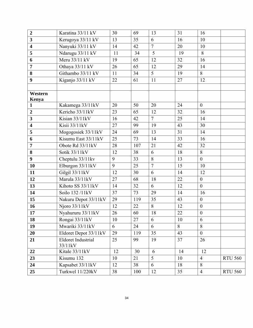
Table 2.4 : Scope of RTUs and Data Region Station Indicati
ons Alarms
Commands
Measurands
Energy Meter Inputs
RTU AVAILABLE
Nairobi 1 Industrial 66/11kV 29 107 21 42 36 RTU 560 2 Kikuyu 66/11kV 26 78 21 43 20 RTU 560 3 Limuru 66/11kV 20 30 15 10 4 Siemens 4 Machakos 33/11kV 16 49 8 21 6 5 Nairobi West 66/11kV 48 174 22 88 40 RTU 560 6 Nyaga 33/11kV 18 28 13 30 2 7 Steel Billets 66/11kV 24 88 15 25 4 8 EPZ 66/33kV &
66/11kV 24 96 12 16 4 RTU 560
Coast 1 Msambweni 12 24 10 13 2 2 Mwabungo 33/11kV 10 22 9 13 2 3 Kanamai 8 22 8 10 2 4 Watamu 7 22 8 10 2 5 Kaloleni 33/11kV 6 14 7 9 2 6 Utange 33/ 11 kV SS 10 24 9 12 2 7 Mbaraki 33/11kV 40 118 24 26 RTU 560 8 Mwatate 33/ 11 kV SS 10 24 9 12 2 Mount Kenya
1 Embu 33/11 kV 22 83 15 36 20
34
2 Karatina 33/11 kV 30 69 13 31 16 3 Kerugoya 33/11 kV 13 35 6 16 10 4 Nanyuki 33/11 kV 14 42 7 20 10 5 Ndarugu 33/11 kV 11 34 5 19 8 6 Meru 33/11 kV 19 65 12 32 16 7 Othaya 33/11 kV 26 65 12 29 14 8 Githambo 33/11 kV 11 34 5 19 8 9 Kiganjo 33/11 kV 22 61 11 27 12 Western Kenya
1 Kakamega 33/11kV 20 50 20 24 0 2 Kericho 33/11kV 23 65 12 32 16 3 Kisian 33/11kV 16 42 7 25 14 4 Kisii 33/11kV 27 99 19 43 30 5 Mogogosiek 33/11kV 24 69 13 31 14 6 Kisumu East 33/11kV 25 73 14 33 16 7 Obote Rd 33/11kV 28 107 21 42 32 8 Sotik 33/11kV 12 38 6 18 8 9 Cheptulu 33/11kv 9 33 8 13 0 10 Elburgon 33/11kV 9 25 7 15 10 11 Gilgil 33/11kV 12 30 6 14 12 12 Marula 33/11kV 27 68 18 22 0 13 Kihoto SS 33/11kV 14 32 6 12 0 14 Soilo 132 /11kV 37 73 29 14 16 15 Nakuru Depot 33/11kV 29 119 35 43 0 16 Njoro 33/11kV 12 22 8 12 0 17 Nyahururu 33/11kV 26 60 18 22 0 18 Rongai 33/11kV 10 27 6 10 6 19 Mwariki 33/11kV 6 24 6 8 8 20 Eldoret Depot 33/11kV 29 119 35 43 0 21 Eldoret Industrial
33/11kV 25 99 19 37 26
22 Kitale 33/11kV 12 30 6 14 12 23 Kisumu 132 10 21 5 10 4 RTU 560 24 Kapsabet 33/11kV 12 38 6 18 8 25 Turkwel 11/220kV 38 100 12 35 4 RTU 560

35
2.1.3 New Remote Terminal Units (RTUs) and Adaptation Works at Substations
This Specification describes the new Remote Terminal Units (RTUs) to be supplied to KPLC as
part of the SCADA for distribution stations project.
The intent of the Specification is to describe KPLC’s needs for the `new RTUs to be provided
and to be integrated as part of the already existing SCADA/EMS system. Each bidder is
encouraged to propose its standard RTUs to the extent possible, as long as it meets or exceeds
the requirements of this Specification.
The Section also describes the equipment and works necessary to interface all controls to be
executed and all data to be acquired from the substation control and switchgear equipment to the
RTUs.
The 48V DC supply equipment for the RTUs and adaptation equipment as well as for the
telecommunication equipment provided under the contract and described in other section of this
document is also specified in subsequent chapters.
2.1.3.1 General information and scope
Site Survey
A site survey to each site shall be conducted by the Contractor’s personnel together with the
Employers Engineers at the beginning of the project to:
Prepare, respectively verify and amend the single line diagrams (SLDs) attached to this
specification. This shall include the primary plant identification for the equipment to be
controlled and monitored;
identify existing substation and transmission line switching procedures including substation
internal inter-lockings;
Determine the exact scope of facilities to be controlled and monitored to enable the final
number of I/O modules required.
While determining the number of I/O, suitability of primary station equipment for control and
monitoring shall be reviewed e.g. availability of CTs, VTs, availability of motors for isolators
and earthing switches, availability of auxiliary switches in the primary equipment.
The scope of the contract does not include supply or rehabilitation of primary substation
equipment e.g. PTs, CTs, respectively CBs, isolators etc. and their driving mechanisms;

36
collect, copy and verify station wiring diagrams required for design of the interface works;
determine the scope and extend of the interface works including connection points,
requirements for synchro check relays and schemes, interposing relays for galvanic isolation,
transducers, cabling and cable trays/trenches etc. This shall include utilization of existing
marshalling cubicles and interfaces where RTUs/SASs are presently installed;
survey existing 48 V batteries, chargers and distribution panels for suitability to feed the
existing and new SCADA and communication equipment;
determine the location of the equipment to be installed under the contract at the time of site
visit, to ensure that locations for installation of new equipment are clearly identified and
agreed upon by the bidders;
36ynchronize of a single RTU unit or distributed RTU within each station. Physical
arrangement at the station primary, control, monitoring and protection equipment and the
required cabling shall be considered.
Remote terminal units
Presently, the NCC and RCCs control and monitor the KPLC Network via 123 RTUs/SAS.
In this project, new RTUs shall be supplied by the Contractor and installed at various substations
within the KPLC Network.
For other stations with existing SCADA, it shall be required that data points that are not
monitored shall be installed and bidders may use spare capacity of existing RTUs/SAS in the
station.
The stations to be equipped with RTUs and the RTU sizing is as detailed in the scope of supply,
Summary of Stations with existing SCADA equipment in the station. The bidders shall
determine the expansion needed to ensure monitoring of all data in the selected stations. The
contractor may use the available spare capacity of the existing SCADA equipment in the station
as long as the specified minimum spare capacity is maintained. Where existing RTU is to be
reused, it shall be the responsibility of the contractor to ascertain the actual status of the RTU and
if need be adapt it accordingly to meet the signals requirements
Table 2-5 below is a List of stations with existing RTU which may be re-used and/ expanded to
accommodate additional station data

37
Table 2-5: Existing RTUs in the scope
Region Station Data Acquisition
protocol
RTU Type
NAIROBI Industrial 66/11kV Direct process interface RTU 560 – ABB
Kikuyu 66/11kV Direct process interface RTU 560 – ABB
Nairobi West 66/11kV Direct process interface RTU 560 – ABB
EPZ 66/33, 66/11kV Direct process interface RTU 560 – ABB
Limuru 66/11kV IEC 61850 Sicam SAS- Siemens
COAST Mbaraki 33/11kV Direct process interface RTU 560 – ABB
WEST KENYA Kisumu 132/33kV Direct process interface RTU 560 – ABB
Turkwel 11/220kV Direct process interface RTU 560 – ABB
Attachment 1:
SCADA System Alarms show details about the controls to be executed and the status indications
measurements, alarms and metered values to be acquired from each individual substation.
An overview of the required RTUs as well as the communication linking to SCADA Systems
can be taken out of Table 1-1 under the details of the scope of supply.
Each individual RTU to be supplied under the Contract shall be fully equipped for the actual
amount of data to be acquired and commands to be executed plus a spare capacity of 25% for
each type of data. The 25% installed spare capacity for the new RTUs to be provided under the
Contract is included in the data count given in Table 1-1 in the scope of supply.
In addition, each RTU shall be expandable in the field by at least 50% of the size of the initial
point capacity of Table 1-1 by addition of Input and Output cards only. The addition of
enclosures, internal cabling/wiring, chassis, or power supplies shall not be necessary when
adding these I/O cards.
The Supervisory Control & Data Acquisition (SCADA) System at the NCC and RCC’s shall be
able to scan the RTUs utilizing the communication network described in chapter 3 of this
document.

38
The Contractor shall be responsible for the complete design, installation, wiring, testing,
commissioning and documentation of the new RTUs, as well as all the works and tasks needed
by the reinstallation/expansion of the existing RTUs, including any required new or parallel
connections to KPLC’s field equipment as described in this Specification.
Data acquisition principles
At all substations where new RTUs are to be installed and existing RTUs are to be expanded
and/or spare capacity 38ynchron, interfacing of the supervisory controls to be executed and data
to be acquired under the project, described above in Chapter 1.2.1 above, under “
Teleinformation plan”, shall be provided.
Interfacing works
The Contractor shall supply and install all necessary equipment and material including
transducers, auxiliary relays, interposing relays, cables, wiring, terminal blocks, test switches,
isolation devices, conduits, cable trays/trenches and any other equipment required to interface the
RTUs with the substation equipment.
The data points shown in Attachment 1(site survey reports) of this specification are wired up to
the existing RTUs either directly from the station control and monitoring equipment or via
interface marshalling cubicles depending on the amount of signals.
The field instrumentation, devices and connections shall not affect the current operation of the
existing substation equipment.
The Contractor shall be responsible to perform any modification to substation facilities to
accommodate the RTU equipment, power supply and other associated equipment as well as to
accommodate the communication equipment supplied and installed under the Contract.
If in some substations with RTU equipment, the existing DC supply system is not in acceptable
conditions, the Contractor shall supply and install in those stations new 48 volts DC batteries,
chargers and associated distribution equipment required to supply the RTU as well as the
communications equipment supplied and installed under the Contract.
All the data points indicated in the Teleinformation plan, which are not yet connected to the
existing RTUs, have to be wired up to the new and/or existing RTUs.

39
The points of interfacing of controls, status indications, measurements and metering at the
substations are mainly the control panels or control desks located at the power station or
substation control and rooms.
At most stations, the origin for acquisition of alarms are the protection panels installed at the
station control rooms or at separate protection rooms.
At all stations, tap changer position indications of OLTC – Interbus transformers are available at
the control panels at the station control rooms.
For measuring of active/reactive power the interface point for acquisition is the control and
protection compartment at the respective cubicles installed at a different room within the station
control building or at the respective outdoor switchyard.
During the design stage of the interface works, the Contractor shall calculate the additional and
the total burden for all CT secondary for all feeders where new transducers are to be installed
under the Contract.
The new equipment shall be adapted to site conditions as:
Station voltage: 30 V DC, 110 V DC, 220 V DC or 240 V AC
CT’s – secondary: 1 A or 5 A
VT’s – secondary: 110/ 3 V or 110/3 V or 100/3 V
2.1.3.2 Functional requirements for new RTUs
Remote terminal units
The new RTUs shall be programmable, with real time clock, 39ynchronized by an external
source, process Input and Output (I/O) modules, CPU, memory and data transmission equipment.
The new RTUs to be supplied and installed under the project shall provide at least the following
functions:
single command outputs, double command outputs
regulation command outputs e.g. raise/lower command outputs for transformer tap
changer control
analog setpoint transmission and output

40
single, double and multiple state digital inputs
analogue measured inputs
metering pulse inputs for acquisition of energy meter values
Sequential Event Recording (SER) with time stamping of events at the RTU
RTU time synchronization
Self testing and diagnostic functions for detection and reporting of any error
automatic re-starting function
Database and parameter setting by menu-controlled dialogues from a local PC and
remotely from the corresponding control centre with downloading function.
Support enrypion and LAN/WAN access
Shall support IEC 61850 protocol for process communication
Bidders shall with their offer inform about the different types of data transmission protocols
available and for the proposed type of RTU.
Telecontrols
The RTU shall have the capability for the SCADA system master station to select and control
specified power system devices. The following power system devices will be controlled by the
RTU:
two-state devices such as circuit breakers and isolators
multi-state devices such as transformer tap changers
Telecommands
The RTU shall ensure that only the correct output is selected for two state devices before
command execution.
Operation of control outputs shall be via a select-check-execute command sequence. The control
sequence shall include the following:
The SCADA system shall transmit a command message addressing the proper RTU and the
control point within the RTU, and indicate the control action desired.

41
The RTU shall initialize its control logic, reassemble the command message, and transmit the
reassembled message to the SCADA system. The message sent to the SCADA system shall be
generated by the RTU’s point selection logic.
The SCADA system shall check the returned message for validity and, if valid, shall issue an
execute command to the RTU.
The RTU shall operate the control point selected only after the execute command has been
received.
The control action shall be executed only if the select-check-execute sequence is performed
without error or interruption. The RTU shall reset its control logic upon any error in the sequence
or if the execute command is not received within a pre-defined time after the command message
is received at the RTU.
The impedance of the output circuit shall be measured to detect jammed contacts.
The point selection logic for the control output shall be designed to preclude operation of an
unselected output under single component failure conditions. That is, no single component
shall be capable of selecting and operating an output point by itself.
In no case, any unwanted telecommand shall be given to the process in case of an RTU power
failure.
The RTU communications protocol shall also support “immediate execute” contact outputs
(where an operation can be commanded without the validity check and execute message
exchange) for control output types such as On Load Tap Changer (OLTC) raise / lower
command outputs.
Analog setpoint control
The RTU shall provide for analog setpoint control and variable pulse width outputs although this
type of control as it would be required for LFC.
Teleindications
Teleindication refers to status information of operational equipment monitored by the system.
Such teleindications include status information of switching devices, event information, alarms,
etc.

42
The RTU shall report teleindications by exception but shall also allow the SCADA system to
demand – scan status data even if the data has not changed.
Status indications
The status (open / closed) of two state devices such as circuit breakers or isolators shall be
acquired by 2 independent, potential – free contacts or by 2 interposing relays, one for each
position. Position indications shall be checked for validity and undefined states like open and
closed (1 | 1) or neither open nor closed (0 | 0) shall be alarmed. The RTU shall provide for run-
time-monitoring, adjustable to the HV equipment operation parameters, to avoid alarming of
undefined states while the equipment (e.g. isolator) is operating.
Alarms
Alarms shall be acquired as single indications via potential – free contacts which are either
available at the initiating equipment or to be generated by paralleling relays to be provided under
the project.
Digital parallel input
The RTUs shall have the ability to handle digital measurands, e.g. four digits BCD. Transformer
tap position shall be coded by means of a diode matrix to a BCD code before connecting to the
digital parallel inputs of the RTU. The Tender shall include complete functional and electrical
specifications of possible input codes and input circuits in the tendered system.
Telemeasurements
Analogue measurements can be acquired from either an analogue input board supplied by the
output of an analog transducer, a transducerless measurement board or a communication network
The analog signals shall be converted to digital mode by an analog-to-digital converter, to which
the inputs are connected. All inputs of a module shall be measured within one cycle, regardless
of the number of inputs in use. Thus new points can be added to the RTU without
reprogramming.
Analog measurements shall be transmitted to the master station with 12 bits or 11 bits + sign bit.
Telemetering
The transmission of integrated totals refers to the transmission of measurable quantities which
are integrated over a specified period of time. The integration shall take place before
transmission.

43
The measured quantity such as active or re-active energy (kWh, kVarh), which is presented as
defined pulses which are read into an integrating register of the RTU from a pulse output or a
closing contact of an energy meter.
Transfers of the accumulated counts into a storage area shall be initiated every 1 minute by the
RTU clock. In case of a failure to scan, e.g. due to failure of the telecommunication system, 1-
minutes integrated totals over a period of not less than 1 day shall be stored at the RTU
Pulse accumulator data shall be assigned to a scan group for scanning of the accumulated values
from the SCADA system.
Sequence of Event Recording (SER)
The RTU shall be capable of Sequence-of-Events (SER) data collection at a time resolution less
than the operating speeds of the power system devices. Any digital input points in the RTU may
be assigned, programmable as an SER data point. In general, a breaker position change and any
alarm from a protection device that has initiated a trip signal is defined as an event for SER.
Multiple transitions of a device, such as the tripping and subsequent reclosing of a breaker,
shall be considered as a series of separate events. Each time an event is detected, the RTU shall
time-tag the event and store it together with the time-tag of the event for transmission to the
SCADA system with the next scan.
The buffer shall be sized to store, as a minimum, a number of events equal to three times the
number of SER points implemented in the RTU.
The time-tag recorded with each event shall be generated from a clock internal to the RTU.
Separating capability
The RTU shall be capable of correctly determining the sequence of events for which their
occurrence is separated by >= 1 ms (separating capability class SP4 of IEC 60870-4)
Time resolution
The resolution of the time tag shall be 10 ms.

44
Common time base
The internal clock of each RTU shall be synchronized either from, a Contractor supplied and
installed time synchronization source, such as a Global Positioning System (GPS) or an omega
synchronizing signal.
The synchronization shall be done periodically such that the time-tags in each RTU shall be
within five milliseconds (5 ms) accuracy between all RTUs.
Tenderers shall clearly indicate the method used for time synchronization and describe in detail
how the required accuracy is achieved.
In the RTU there shall be a digital output from which time synchronization messages can be
forwarded to external devices. The frequency of the activation of the message shall be adjustable.
Data transmission
The data transmission network will consist of dedicated data channels and/or TCP/IP network
utilizing fibre optic transmission media, power line carrier and radio transmission.
The RTU shall be capable of providing both legacy and cutting edge communication interfaces.
The new RTUs shall be capable of “dual port function”, utilizing different protocols on at
minimum 2 separate RTU communication ports simultaneously. Communication protocols
shall be implemented by modifiable firmware in the RTU. Reconfiguration of the RTU database
may be necessary when an RTU’s communications protocol is changed due to the difference in
the functions supported by the protocol.
The Contractor shall provide and implement RTUs with standard IEC 60870-5-101
communications protocol as well as IEC 60870-5-104 communications protocol. Both protocols
shall be included and shall be selectable for each of the RTUs by parameterization. The
interfaces to the different communication media for IEC 60870-5-101 and IEC 60870-5-104
shall be provided by the RTU hardware.
The RTU protocol shall be non-proprietary for use within KPLC. The Contractor shall provide
all details and parameter settings used under the IEC 60870-5-101 and IEC 60870-5-104
protocols. KPLC shall be authorized to disclose the RTU protocol to third party suppliers.
45
1.1.1.1 Functional requirements for adaptation works
This Section is dealing with the interfacing equipment and works to be performed at the
substations.
Analogue and digital input data to RTU
Power system analogue and digital input data shall be collected from the substation field
instrumentation and provided to the RTUs. Interfacing shall be designed to minimize
electromagnetic and electrostatic interference. Galvanic isolation shall be provided for all inputs
and interposing relays shall be used.
Analogue measurements
The interfacing shall consist of analogue transducers, isolating/test devices, wiring, cabling and
terminations to the secondary PT/CT circuit in the control or relay cabinets. The output signal
from the analogue transducer shall be transmitted to the appropriate input at the RTU. This refers
i.e. to MW/MVAr, Current and Voltage measurements.
Status indications
The interfacing shall use spare potential free contacts where available or auxiliary paralleling
relays to be provided under the Contract, (one independent contact / relay for each position)
actuated by the switchgear equipment, isolating and test devices, wiring, galvanic isolation,
cabling and terminations to the digital input point at the RTU.
Alarms
Input wiring to the RTU from alarm points shall use spare contacts available on the actuating
device wherever possible. Where spare contacts are unavailable, auxiliary “contact multiplying”
relays shall be supplied and wired to provide the required digital input signal to the RTU with
galvanic isolation.
Pulse accumulation
The pulse accumulation interfacing shall utilize potential-free pulse contacts or pulse outputs of
electronic meters if available, isolation and test devices, wiring, cabling and terminations to the
RTU. Where potential free pulse contacts or pulse outputs are not available, new meters shall be
provided under the Contract.
Supervisory control interface

46
The substation adaptation works for device control will be required to take an output signal from
the RTU, actuate an auxiliary control relay, and have a contact from the control relay to initiate a
control action such as breaker trip/close, etc. on the substation equipment by the appropriate
connections to the substations equipment control circuits.
The supervisory control interface shall consist of outputs from the RTU, interposing relays,
isolating/test devices, and wiring, cabling and terminations to the appropriate control circuits and
control relays and switches in control cabinets.
Each RTU control output shall drive an auxiliary control relay, which shall be located in the
control panel or locally. The interposing relay shall be normally de-energized during normal
operation. A normally open contact of these interposing control relays shall actuate a breaker
tripping/closing coil. In no cases shall the relay contacts supplied in the RTU directly control any
equipment.
The circuit breaker close command in stations where separated networks / generation could be
switched shall pass through synchro-check relays to prevent CB closing under none-synchronous
conditions. Installation of synchrocheck relays under this contract is part of the project tasks
under the Contractors responsibility.
In no case shall the closing commands for circuit breakers by-pass any station internal
interlocking.
For OLTC devices, appropriate latching relays shall be utilized.
A key type selector switch shall be installed for each feeder equipped for remote control from the
corresponding Control centre. The switch shall allow selection of control from the Control centre
or from the substation and its position shall be indicated at the corresponding Control centre.
The Contractor shall provide and install suitable test switches or isolating devices for all control
points, to allow for proper control isolation, testing, safety procedures.

47
2.1.3.3 Equipment characteristics
Remote terminal units hardware
Enclosures
The Contractor shall provide enclosures meeting the following requirements:
Swing racks supported by heavy gauge hinges shall be provided so that only front access to
components and wiring is required for routine maintenance and troubleshooting.
Provisions for top and bottom cable entry. Cable entries shall be provided with protection
against insect and animal entry, and sealed to prevent dust and sand contamination.
Protection class of the enclosures shall be
for indoor cabinets IP52 minimum
for outdoor cabinets IP64 minimum.
Suitable signal and safety ground networks within the enclosure.
Convenience outlets at 230 V AC, shall be provided.
Power supply
The Contractor shall supply any hardware required to convert the 48 V battery voltage to the
required internal voltages for the RTU hardware. The RTUs shall be capable of operating with
ungrounded or grounded (either polarity) input power.
In RTU DC distribution, Miniature Circuit Breakers (MCBS) with alarm contact shall be used,
i.e. fuses are not accepted.
Control disable switch
For each station a manual key type selector switch shall be provided to locally disable all control
outputs at a station. The key-type selector switch shall be installed at the RTU such that it can be
operated without opening the RTU panel. The outputs from the RTU shall be disabled by
breaking the power supply connection to the control output. An auxiliary contact on this switch
shall be wired to a contact input in the RTU to report the control disable switch’s status to the
SCADA system.
Interconnections
All connections between the RTU’s termination facilities and signal wiring shall be through
barrier-terminal blocks with knife-switch isolation, mounted in the RTU panel or an adjacent
marshalling cabinet, if not already exist in the Substation. Terminal blocks shall be screw-type,

48
with full depth insulating barriers. There shall be galvanic isolation of all signal wiring via
interposing relays
Distributed RTUs
RTUs shall have the capability to gather data from other smaller or distributed RTUs or local
intelligent substation instrumentation using standard RJ45 Ethernet , or directly connected RS-
232C- or RS 485- channels with or without modems. The distance between the different control
locations may reach up to 500 m.
Digital inputs
The digital inputs shall be opto-isolated, signal voltage 48 V DC. Other voltages shall also be
possible by changing the matching resistor in the input circuit.
Contact bouncing of the interposing relays shall be filtered. The bounce filtering time shall be
7ms. Input circuits with selectable bounce filtering time setting are preferred.
The indications shall preserve the chronological order of events inside the RTU.
Oscillating inputs as a result of e.g. a faulty relay chattering shall be blocked locally at the RTU.
Analogue inputs
In analogue measurements, the information to the analog input modules of the RTU is given in
the form of analog current supplied by the output of measuring transducers. Measuring
transducers shall normally be installed in the switch/control gear.
In analog input modules, the following current input ranges shall be available:
unipolar 0-5 mA, 0-10 mA, 4-20 mA, 0-20mA
bipolar +/- 5 mA. +/-10 mA,+/-20mA
It shall be possible to change the input range for each individual input, preferably by software
means, instead of changing the input resistor.
The analog input circuit shall have a precise DC impedance less than 200 ohms for current
inputs. This impedance must not vary more than half of the accuracy of the Analog to Digital
Converter (ADC) with influence values such as temperature, etc.
In the input circuit galvanic isolation shall be provided from mechanical earth and electrical
earth, and, preferably, between different inputs.

49
The circuits of the analog input module shall be protected against disturbances caused by
switching transients and against disturbances from power and radio frequencies present at
outstations.
The scanning of each input shall not introduce any error on the analog information.
For each input it must be possible, without disturbing the other inputs,
to isolate the input from the ADC and close the analog circuit,
to connect, on the ADC side, a test set for maintenance or adjustments,
to measure the analog input value without disturbing the measurement (addition of an
mA meter over a link which is then disconnected).
The analog information shall be converted into digital value by the ADC which can be common
for all inputs. Analog measurements shall be transmitted to the master station with at least 11 bits
plus sign bit.
The total accuracy must be better than 0.5% of the nominal range of a measurement calculated
from RTU’s analog input up to Control Centre. A calculation of the total accuracy in the wide
sense as well as in the restricted sense as per IEC 870 – 4 shall be included in the Tender.
The input circuits must withstand a permanent overload of 30% without any damage.
In case of input overload the output message shall be either
the exact value corresponding to the input or
the maximum value that is possible to code (with the correct sign).
Pulse inputs
The counter register shall be 16 bit. The maximum input frequency shall be 25 Hz. In practice,
the pulses will be dimensioned in a way that max. frequency is less than 5 Hz. Interposing relays
will not be used.
RTU firmware requirements
The RTUs shall meet the following characteristics of the firmware to support the functions of the
RTUs. The Contractor shall use standard firmware as much as possible.

50
All firmware shall be completely and consistently documented. It shall not be necessary to
perform modification to firmware, logic, or data for expansion within the sizing parameters
defined for the RTU.
At the time the RTU is accepted, all firmware delivered must be up to date and in final form,
including all standard firmware changes and field changes initiated by the Contractor or the
Contractor’s suppliers prior to acceptance. The firmware documentation must reflect these
changes.
Firmware shall be loadable by service notebook locally at minimum, download of firmware and
parameter sets trough SCADA system, using the data communication links will be preferable. In
any case changing of EPROMs or similar devices shall not be necessary when updating RTUs
firmware.
Initialization / restart program
Firmware shall be provided to enable the RTU to restart itself upon manual request and
automatically under the conditions of power restoration, memory parity errors, and hardware
failures. The firmware shall initialize the RTU and begin execution of the RTU functions without
intervention by the SCADA system. All RTU restarts shall be reported to the SCADA system.
Fail safe processing
In the case of irrecoverable faults such as power supply failures, firmware malfunctions, or any
other detected condition that may affect the security of indications and controls, the RTU shall
place itself in a secure state that prohibits the transmission of false indications or the execution of
erroneous control outputs. The detection of these error conditions shall be the responsibility of
the RTUs self-test and operations monitoring firmware.
Database maintenance
The Contractor shall supply software to configure each RTU’s database where this information is
located in software and/or firmware at the RTU. The software shall completely generate or
modify the database of the RTUs. The database software shall have error detection services and
shall produce a printed listing of the input data and the resulting RTU database configuration.
Down loading of database from SCADA system

51
The RTU shall support the change of the RTU’s configuration and processing parameters by
messages from the SCADA system. These changes shall include, but not be limited to scan
group definitions, analog limits, SER point allocation and buffer definitions.
Diagnostic firmware
The Contractor shall supply diagnostic firmware for both off-line local tests and on-line self-
diagnostic capability built into the RTU. The RTU shall enter an off-line state during the
execution of off-line diagnostics, and this off-line state shall be reported to the SCADA system.
The RTU shall include a remote diagnostics communication port and shall be capable of
executing off-line diagnostics from an external computer terminal connected to this remote
diagnostics port.
Interfacing equipment
Interposing relays
Interposing relays for telecommands and digital inputs shall be provided by the Contractor.
The relays shall be installed in the switch / control gear and shall have the following
characteristics:
For telecommands:
Coil voltage shall be 48 VDC; Coil voltage variation shall be +-20%.
Signal voltage on the contact circuit shall normally be 110 VDC, but other voltages may also
exist.
The rated contact current shall be minimum 5 ADC making/breaking. In exceptional cases,
where CB coils are to be switched directly by the interposing relay, installed under the
contract, additional contactors might be required to cope with the switching currents of the
CB coils. In such cases, these contactors shall be provided under the contract.
For teleindications:
Coil voltage shall normally be 110 VDC; (other voltages may also exist) coil voltage variation
shall be 20%.
Signal voltage on the contact circuit shall be 48 VDC.

52
The rated contact current shall be minimum 3 A DC making/breaking and 1 A continuously
Relays with two (2) normally open and two (2) normally closed contacts shall be provided.
Contact bounce shall be less than 8 ms and contact age shall be 10 exp. 6 operations.
Dielectric strength shall be 2 kV, 50 Hz-1 min between one circuit and the earthing point and
between independent circuits, 1 kV, 50 Hz for 1 min between two terminals of the same circuit,
Impulse test voltage: 5 kV (IEC 60255-5).
Plug-in type relays and sockets shall be used with sockets directly mounted on a DIN rail.
All necessary arrangements must be made so that the plugging – in and out are easy and
performed without any risk of damaging of relay parts.
The relays shall be fitted with a visual operation indicator (either mechanical or LED).
Transducers
The new transducers shall be of the latest state-of- the art solid state technology, not requiring
frequent calibration and preventive maintenance and shall be free from electro-magnetic
interference and noise. They shall use electronic surface components and all its internal parts are
protected by a tropicalization varnish. Transducers shall comply with the latest international
standards and, mandatory, to the IEC 60688-1 publication.
Transducers shall be programmable and the respective programming equipment/software shall be
provided in this contract.
Transducers shall in general be installed in the control or protection board of the switchgear
equipment. Transducers shall preferably be plugged into a safety socket and shall be easily
removable and replaceable during operation. If the transducer uses current circuits, these circuits
are automatically shorted when extracting the transducer from its socket.
Transducers shall comply with the following requirements:

53
Accuracy of the measurements for MW, MVAr, voltages shall be better than 0,5% of full
scale over a temperature of 0 to 50 °C.
Maximum ripple shall not exceed 2% peak to peak.
Response time to 99% of final value shall not exceed 0.5 sec.
The analogue output of the transducers inputs to the RTU shall be isolated, unipolar or
bipolar, 2 – wire Load independent DC current of 0 to 10 mA, or ±10 mA or 4-20mA.
Transducer burdens shall not exceed 2 VA per PT element and 2 VA per CT element. The
contractor shall provide calculations of the additional burden imposed by the transducer and
the associated wiring / cabling for each transducer installed under the project during the
detailed design stage of the project.
Transducers shall be able to withstand a short period (1 second) overload of up to 50
A without damage and have a withstand voltage of 4 kV/50 Hz/ 1 min and 5 kV/1.2/50 µs,
according to IEC 60255-4 C1. III.
Frequency transducer shall have an input range from 45 Hz to 55 Hz.
Active and re-active power measurements shall be made 3 phase – 3 wire for distribution indoor
switchgear circuits and 3 phase – 4 wire for other circuits.
A single phase-to-phase voltage shall be acquired for each measurement point. Voltage
transducer shall provide for expanded scale of +- 20% of the rated voltage.
OLTC transformer tap positions are available either in analogue form or from drum switches
with individual switches for each tap position (e.g. one out of 19).
Transformer tap position from the drum switches shall be coded by means of a diode matrix to
two digit BCD code before connecting to the digital parallel inputs of RTU.
For transformer tap position available in analogue form, analogue transducers shall be provided.
These transducers shall convert the current tap position of the TC to a suitable sealed analogue
input to the RTU.
Cables

54
The instrumentation cables from the RTU electronics cabinet to the interface terminals at the
substation control / switchgear shall be delivered by the Contractor.
The characteristics of the cables shall be as follows:
Number of cores n * (2+1) * 0,8 = 2, 4, 8, 12, 24, 48, with 2 + 1 = a pair of conductors +
surrounding screen and 0.8 = cross-sectional area of screen.
The outer PVC sheath shall be rodent proof and meet flame test requirements of IEC 60323-3
category C. Manufacturer’s name, manufacturer’s type, core quantity and cross-section, year
and month of manufacturing shall be indicated.
Individual leads shall have colour coding.
Pair-twisted cores, each pair and the whole core surrounded by protective screen shall be used
for connection of transducer secondaries to the RTUs. For connection of controls, status
indications and alarms cables with protective screen surrounding the whole core are
acceptable.
In the design made by the Contractor the following shall be taken into account:
Separate cables shall be used for:
telecommands,
teleindications and alarms
measurements transducer secondary outputs (mA)
metering (kWh)
The number of cables should be as low as possible.
2.1.3.4 Power supply for substations
At all stations where no adequate power supply exists and new RTUs and telecommunication
equipment shall be installed, the Contractor shall supply, install and wire a new and complete
48V DC power supply system including a 48V DC battery, charger(s), low voltage disconnect
switch, all DC distribution equipment and cabling required for the uninterruptable supply of 48V
DC power to the RTU as well as the communications equipment provided under the Contract.
The battery and charger sets shall be sized to adequately supply the loads to be connected to the
battery. The rectifier output shall be k x S where

55
k = 1.5
S = sum of the following:
input power in kVA of the largest tendered RTU
input power to the new telecommunication equipment provided under the contract.
The battery capacity shall be C = 1.5 x Cn , where Cn is the capacity to feed the above total load
for eight (8) hours.
The battery chargers shall provide normal system power and shall be capable of recharging a
fully discharged battery in twelve hours while supplying normal system power. The chargers
shall have 240 volt, 1 phase input power. Where duplicated chargers are to be provided, both
chargers shall have an output diode in the positive pole to prevent back-feeding a failed charger.
The batteries shall be sealed, maintenance free lead acid type. As they are sealed, there are no
special ventilation requirements, and as such the batteries may even be placed in the substation
control rooms or communications equipment rooms.
A low voltage disconnect switch shall be provided for protection of the battery. The 48 Volt DC
system distribution panel shall be a fused switch distribution panel board. The low voltage
disconnect switch and fuse panel shall be provided with local alarms as well as alarm contacts.
The low voltage disconnect switch shall be equipped with external by-pass switch to be used for
maintenance purposes.
2.1.3.5 Spare parts and test equipment
Spare parts
The Contractor shall furnish a list of recommended spare parts and test equipment for the
purchased RTUs to maintain reliable RTU operation. The spare parts list shall be subdivided
into:
short-term spare parts that are necessary for two (2) years of operation. These spare parts shall
be included in the contract.

56
long-term spare parts that are necessary for ten (10) years of operation.
The Contractor shall guarantee the availability of spare parts for a period of at least 15 years and
shall make available at no cost to KPLC the manufacturing drawings and rights to manufacture
those subassemblies which the manufacturer will not support, or discontinues support thereafter.
For each subassembly, the specific components supplied shall be identified and referenced in the
supplied documentation.
Portable test set
The Contractor shall supply 2 portable RTU test sets (notebooks) for testing RTU operation.
Each test set shall be capable of emulating communications from both the SCADA system and
the RTU. The test sets shall have the capability of interfacing to an RS232C serial port for the
RTUs being supplied on the project. Test sets shall be capable of passively monitoring all
communication traffic on a channel without interfering with channel operation.
In addition each test set shall include interface testing equipment for simulation of digital and
analogue inputs, digital and analogue outputs.
Ferrule Marking Machine
The contractor shall supply 2 no. ferruling machines. These shall be used for maintenance works
in the substations.
The ferrule marking machine shall have the following specifications;
Technical Description/Specification
Ferrule Printing Machine High-speed marking Marking speed at 35mm/second. Mark 50pcs
of 20mm-lengthtube per min.
Maximum printing length Tube : 20M Tape : 5M
Maximum 100,000 character internal memory storage
Easy access to your PC with application software
Can import text and setting data from PC with USB 2.0 Interface for faster & big-volume
markings.
Marking method Thermal transfer method(300dpi)
Display LCD dot matrix : 64 x 160 Pixel (Backlit)

57
Marking speed 35mm/s(Standard) 20mm/s(Low temperature mode)
Maximum No. of characters to input 5,000 characters
Character size 2,3,4,6mm height (PVC, Shrinkable tube)
Ferrule Printing Machine Usable tape size Width 5,9,12mm
Tube cutting method Auto half cut, manual full cut
Ferrule Printing Machine Internal memory 100,000 characters (50 files)
Ferrule Printing Machine External memory: USB Memory
Power supply DC 12V, 3.3A Use only specified AC adapter (100V-240V) appended to
machine.
Power consumption 16W (max.)
Operating environment 10 to 35 degrees Celsius
2.1.3.6 RTU performance requirements
Availability
An availability of 99.9% is required exclusive of communication channel availability. An RTU
shall be considered unavailable when:
any function is lost for all points of a single type
one input card or output card of each type fails
More than one input card or output card of the same type fails.
Maintainability
The RTU design shall facilitate isolation and correction of all failures. The following features
which promote rapid problem isolation and replacement of failed components shall be included:
self-diagnostic capabilities continuously monitoring operation of the RTU
on-line error detection capabilities including detection of memory, CPU, communication
faults, and input/output errors and failures with detailed reporting of detected errors to the
SCADA system
Local indication of RTU failures.
Message security

58
Each message transmitted shall include an error detection code to exclude erroneous messages
being accepted as valid.
2.1.4 Guaranteed Technical Particulars
Table 2-4 Guaranteed Techinical Particulars
SCADA EQUIPMENT FOR SUBSTATIONS
Tender Schedules Unit Tendered Data
1. Remote Terminal Units
Manufacturer
Type
Dual Port Capability
Supported communication protocols
IEC 60870-5-101 on both channels
IEC 60870-5-104 on both channels
Transmission speed channel 1 Bit/s
Transmission speed channel 2 Bit/s
Remote Terminal Capacity:
Total number of analog inputs
Total number of status inputs (one/switch)
Total number of status with memory inputs
Total number of alarm inputs
Total number of MWH and MVARH
accumulator inputs
Total number of control outputs
Total number of analogue outputs
Transmission time:
single-point commands Sec
single-state indications Sec
measured value correction Sec
Data Priority facilities

59
Permissible signal distortion for safe operation %
Accuracy of the entire measuring loop
metering transducers Max. %
transmission equipment Max. %
Measured value-input mA
output mA
at 1 Ohm
load impedance
digital output
Power supply voltage V DC
Power consumption fully equipped W
Mode of operation
commands
indications
measured values
Pulse train code
address-bloc
information-block, indications
measured values
commands
metering readings
check bits
Hamming Distance
Dimension of RTU cabinets and Marshalling
Cubicle (packs) completely equipped and
wired
height cm
width cm
depth cm
Protection class for cubicles (IP 52 min.)

60
2. Voltage transducer
Manufacturer
Type
Accuracy (at ambient temp. 0 – 50°C) %
Ripple (peak to peak) %
Response time to 99 % of final value sec.
Input voltage V
Output current mA DC.
Auxiliary voltage V DC.
Test voltage (input to earth) kV
Power consumption VA
Module dimension cm x cm
3. Transducer for active / reactive power
Manufacturer
Type
Accuracy (at ambient temp. 0 – 50°C) %
Ripple (peak to peak) %
Response time to 99% of final value sec
Frequency Hz
Input
current A
voltage V
Output current mA DC.
Test voltage (input to earth) kV
Power consumption VA
Auxiliary voltage V
Module dimension cm x cm

61
4. Current transducer
Manufacturer
Type
Accuracy (at ambient temp. 0 – 50°C) %
Ripple (peak to peak) %
Response time to 99 % of final value sec.
Output current mA DC.
Auxiliary voltage V DC.
Test voltage (input to earth) kV
Power consumption VA
Module dimension cm x cm
Module dimension cm x cm
Ripple (peak to peak) %
Response time to 99 % of final value sec.
Input voltage V
Output current mA DC
Auxiliary voltage V D.C.
Test voltage (input to earth) kV
Power consumption VA
Module dimension cm x cm
5. Frequency transducer
Manufacturer
Type
Accuracy (at ambient temp. 0 – 50°C) %
Ripple (peak to peak) %
Response time to 99 % of final value sec.
Input voltage V
Output current mA DC

62
Auxiliary voltage V D.C.
Test voltage (input to earth) kV
Power consumption VA
Module dimension cm x cm
6. Interposing relays for supervisory control
Manufacturer
Type
Operating voltage
coil V D.C.
contacts V D.C.
Test voltage kV
Number of N.O. contacts
Switching cycles lifetime (mech.)
7. Interposing relays for status indication
Manufacturer
Type
Operating voltage
coil V D.C.
contacts V D.C.
Test voltage kV
Number of N.O. contacts
Switching cycles lifetime (mech.)
8. Ferrule Marking Machine
Manufacturer
Type
Operating voltage
Weight
Dimensions

63
2.2 Integration of the new stations to the SCADA/EMS system
2.2.1 General Information
Data Engineering Tool (DE400) is the application software package used for off-line data entry
of the Network Manager SCADA/EMS/DMS system. The tool is used for both the initial process
data entry and for the process data maintenance. The tool is commonly referred to as DE400.
After all the offline data engineering is performed, DE 400 tool is used for either incremental or
total population of the real-time Network Manager Avanti Database population
2.2.2 Data Population
It shall be in the scope of the contractor to generate the individual station displays and populate
the KPLC’ Network Manager system database with all the station data, for full SCADA
operability. All the data engineering work shall be done in close consultation with the KPLC
SCADA/EMS experts.
The complete database population shall be handled by a professional who fully understands and
is well experienced in the functions of the Data Engineering tool (DE 400) and the Network
Manager SCADA/EMS system as a whole.
Tests shall be required to ensure the data-flow from the RTUs up to display presentation and vice
versa.
There are available workstation equipment that serve as maintenance and training/operator
console at the NCC and all other control centres. These workstations also have the data
engineering software which the contractor’s expert may use for the required database population
and station displays and reports

64
2.2.3 RTU and SCADA tests
2.2.3.1 Factory Acceptance Tests
The RTUS shall pass agreed set out tests before they may be shipped to site. KPLC shall witness
FATs unless he waives this in writing. FAT preparation costs shall be borne by contractor except
transport and accommodation, which shall ne catered for by KPLC. FAT shall be carried by two
KPLC staff for 5 days.
2.2.3.2 Site acceptance Tests
The RTUs shall pass agreed set out tests before they may be put into operation and before they
are handed over to the employer. The RTUs will be accepted by KPLC if both:
The RTUs and all items of the equipment have successfully completed all the specified tests
All failures, problems and reservations noted during the tests have been corrected to the
satisfaction of KPLC.
If either of these conditions has not been complied with, then the necessary corrective action
shall be agreed between the Contractor and KPLC.
2.2.3.3 Commissioning Tests
After completion of RTU interface works in the stations all type of inputs / outputs at the
stations’ RTUs, shall be tested from National or Regional Control Centres. The tests
shall include:
Remote control of circuit breakers, isolators and transformer tap position.
Status indication of circuit breakers, isolators, earthing switches, transformer tap position.
Indications shall be manually selectable but shall also react to remote controls as the actual
devices at the substation e.g. open, close, intermediate position, different time behavior, out of
tap etc.
single digital input to confirm persistent and fleeting alarms
adjustable analog input in the range of 0…100%
adjustable analog input in the range of -100%…0…100%
Energy counter to simulate energy meter readings.

65
2.3 TRAINING
1. The Contractor shall provide 2 weeks training for 2 (two) KPLC staff at the supplier’s
factory premises and on site during installation works and the scope of each service shall be
given.
The training shall cover configuration, testing and commissioning of the RTU/gateway supplied
by the contractor.
On completion of the training, KPLC staff shall be able to modify and make changes to the
configuration of the supplied RTU to accommodate any future changes as well as interfacing &
data transmission to the NCC/RCC.
All training costs shall be borne by Contractor except travel to manufacturers place and
accommodation which shall be borne by KPLC. The scope of each service shall be given. The
training content shall be subject to approval of the project Manager.
2. In addition to the basic SCADA equipment training , the contractor shall also be required to
provide 2 weeks training for an 2 (two) Engineers at the supplier’s factory premises or a
recognized industry training institution subject to approval by the project Manager on station
automation protocol IEC61850.
The training IEC61850, basic and advanced training shall include but not be limited to:
Principles & Models (Design Principles, Information Modeling, Interoperability,
Architecture: Station & Process Bus, Logical Nodes, ACSI – Class Models, DataSet,
Communication models, Controls
COMMUNICATIONS ( GOOSE / GSSE, Client / Server, Data Reporting &
Logging, Sampled Values, Time Synch, GOOSE & Ethernet Frames, 7-OSI Layers &
PRP/HSR, Client / Server MMS Protocol, ASN.1 Encoding & Message Parsing
LANGUAGE (SCL Syntax and Semantics, .ICD/.CID Files: IED definitions.
SCD File: Substation Section, Access Points & Communications, Engineering
process: Configuration, Mandatory Software Tool
HANDS – ON ( Create DataSets& Control Blocks, Configure GOOSE & Data
Reporting, Connect to Live IEDs, Monitor & Troubleshoot Messages, Perform
complex GOOSE Testing, Initiate Client/Server MMS Reporting, Message Parsing:

66
Apply ASN.1 BER encoding, Simulate IEC 61850 IEDs, Import SCL Files, Connect
Import Setup, IEC 61850 Engineering)
CHAPTER THREE
3 TELECOMMUNICATIONS
3.1 FIBER OPTIC LINKS
The Detailed Technical Specifications for the fiber telecommunications solution shall be
set out as follows;
1. The fiber optic cable specifications
2. Fiber Optic Test Equipment Specifications
3. The fiber optic terminal equipment specifications
4. The fiber optic cable & terminal equipment Spares requirement
5. Testing
6. Training
3.1.1 GENERAL
KPLC intends to integrate several existing distribution substations yet to be automated to the
existing SCADA infrastructure.
This shall employ the use of various telecommunication solutions to connect these substations to
their respective regional control centres for primarily SCADA connectivity and additionally for
telephony and office data connectivity.
The telecommunication scope of work, fiber optic links, shall be as follows;
DISTRIBUTION SUBSTATIONS

67
Station Link End SS Approx
Link
Distance
(kms)
Link
Available
Proposed
Link
Equipment
NAIROBI REGION – STATIONS CONNECTED TO NCC
1. Donholm 11kV NAIROBI
SOUTH
6 YES Switches
2. Industrial 66/11kV NAIROBI
SOUTH
8 NO Switches
3. Karen 66/11kV NAIROBI WEST 14 YES Multiplexer
4. Limuru 66/11kV NAIROBI
NORTH
15 YES Switches
5. Athi River 33/11kV EMBAKASSI 26 YES Multiplexer
6. Machakos 33/11kV EMBAKASSI 61 YES Multiplexer
7. Nairobi Airport 66/11kV EMBAKASSI 10 YES Switches
8. Nyaga 33/11kV RUIRU SS 15 NO Switches
9. Muthurwa (new) NAIROBI
SOUTH
8 YES Switches
10. EPZ ATHI RIVER SS 3 YES Switches
COAST REGION – STATIONS CONNECTED TO RABAI RCC
10. Msambweni 33/ 11kV Mwabungo
33/11kV
20 NO Switches
11. Mwabungo 33/11kV GALU SS 5 NO Switches
12. Kanamai 33/11 kV SS NEW BAMBURI 18 NO Switches
13. Watamu 33/11kV KAKUYUNI SS 15 NO Switches

68
14. Kaloleni 33/11kV RABAI SS 30 NO Switches
15. Malindi 33/11kV KAKUYUNI SS 30 YES Multiplexer
16. Utange 33/ 11 kV SS NEW BAMBURI 12 NO Switches
17. Shanzu 33/11kV NEW BAMBURI 5 YES Switches
18. Mwatate 33/ 11 kV SS VOI 20 NO Switches
19. NEW BAMBURI RABAI SS 40 NO Multiplexer
MT KENYA REGION - STATIONS CONNECTED TO KIGANJO RCC
19.
.
Embu East SS KUTUS SS 15 YES Switches
20. Embu 33/11kV KUTUS SS 25 NO Switches
21. Karatina SS KIGANJO 132 25 NO Switches
22. Kerugoya SS KARATINA SS 20 NO Switches
23. Ndarugu 33/11KV MANGU SS 10 NO Switches
24. Meru 33/11kV MERU 132 8 YES Switches
25. Othaya 33/11kV RURINGU SS 21 NO Switches
26. Githambo 33/11kV GITHAMBO 132 21 NO Switches
WEST KENYA REGION - STATIONS CONNECTED TO LESSOS RCC
27. Kakamega 33/11kV MUSAGA SS 22 YES Multiplexer
28. Kericho 33/11kV CHEMOSIT SS 25 YES Multiplexer
29. Kisian 33/11kV KISUMU 132 14 NO Switches

69
30. Kisii 33/11kV KISII 132 18 YES Switches
31. Kisumu East 33/11kV KISUMU 132 16 NO Switches
32. Obote Rd 33/11kV KISUMU 132 4 YES Multiplexer
33. Elburgon 33/11kV SOILO SS 10 NO Switches
34. Gilgil 33/11kV LANET SS 33 YES Multiplexer
35. Soilo LANET SS 33 YES Multiplexer
36. Njoro 33/11 kV SS SOILO SS 15 NO Switches
37. Nyahururu 33 /11 kV RUMURUTI SS 35 NO Switches
38. Rongai 33/11 kV SS SOILO SS 5 NO Switches
39. Mwariki 33/11 kV SS NAKURU
DEPOT
5 NO Switches
40. Eldoret Industrial
33/11kV
RIVATEX 8 NO Switches
41. Kitale 33/11kV KITALE 132 20 NO Switches
42. Kapsabet 33/11kV LESSOS 20 YES Switches
43. Turkwel220 kV LESSOS 230 NO ETL 600 PLC
Terminal Eqpt
3.1.2 FIBER OPTIC CABLE SPECIFICATIONS
This cable shall be installed onthe distribution network below the 66kV, 33kV and 11 Kv power
lines.
These extensions shall originate from the existing fibre optic nodes at various locations inthe
power supply network in all the KPLC Regions.

70
For technical and administration purposes, KPLC is divided into four administrative regions
namely Nairobi, Coast, Mt. Kenya and West Kenya respectively.
The total estimated cable length to be installed in this phase is approximately 426Kms
broken down into FOUR lots as per regional requirement.
3.1.2.1 ENGINEERING
Fibre Optic Cable: A cable that contains individual glass fibers, designed for the transmission
of digital information, using light pulses
All Dielectric Self Supporting (ADSS): A cable that is designed for aerial applications and does
not require a separate cable messenger.
OTDR: Optical Time Domain Reflectometer: A device used for characterizing a fiber,whenever
an optical pulse is transmitted through the fiber and the resulting backscatterand reflections are
measured as a function of time.
Single Mode Fiber (SM): An optical fiber with a small core diameter in which only asingle
mode of light is capable of propagation.
Multi-mode Fiber: An optical fiber whose core diameter is large compared with the optical
wavelength and which, consequently, a larger number of light modes are capable of propagation.
Splicing: Making a permanent junction between optical fibers. This may be thermally fused or
mechanically applied.
Minimum Bend Radius: The minimum radius a fiber may be bent before optical losses are
induced
ODF- Optical distribution frame
3.1.2.2 PROJECT SUMMARY AND DESIGN PRINCIPLES FOR THE ADSS FIBER OPTICAL CABLE
The basic information and design principles for the ADSS Fiber Optic in this project is only
meant to offer general guidelines to the tenderers and is only meant to assist in the preparation of
bids. Further details and more precise information are expected to be obtained during the site
visits and route surveys which are mandatory.
1. Proposed Links

71
The Distribution stations outlined below are expected to be connected to their respective regional
control centres via fiber optic cable. The concept is that ADSS cable be run from these stations
up to the backbone node where there is existing fiber optic cable already to the control centre.
These stations (Distribution Stations) and their link ends (Origin)are as indicated in Table 1
following;
Table 3-1 Estimated Distances
REGION DISTRIBUTION
STATION ORIGIN
APPROXIMATE
DISTANCE
(KM)
Nairobi Industrial SS Nairobi South SS 8
Nyaga 33/11 SS Ruiru S/S 15
SUB TOTAL 23
Coast Msambweni 33/11 kV Mwabungo 33/11 kV 20
Mwabungo 33/11kV Galu SS 5
Kanamai 33/11 kV SS New Bamburi SS 18
Watamu 33/11kV Kakuyuni SS 15
Kaloleni 33/11kV Rabai SS 30
Utange 33/ 11 kV SS New Bamburi SS 12
Shanzu33/ 11 kV SS New Bamburi SS 5
Mwatate 33/11 kV SS Voi SS 20
New Bamburi 132 Rabai SS 35
SUB TOTAL 160
Mt Kenya Embu East Kutus 15
Embu 33/11 kV Kutus 25
Karatina SS Kiganjo 132 25
Kerugoya SS Karatina SS 20
Ndarugu 33/11KV Mangu SS 10

72
REGION DISTRIBUTION
STATION ORIGIN
APPROXIMATE
DISTANCE
(KM)
Othaya 33/11kV Ruringu SS 21
Githambo 33/11kV Githambo 132 21
SUB TOTAL 137
West Kenya Kisian 33/11kV Kisumu 132 14
Kisumu East 33/11kV Kisumu 132 16
Elburgon 33/11kv Soilo SS 10
Njoro SS Soilo SS 15
Nyahururu 33/11kV RumurutiSS 33
Rongai SS Soilo SS 5
Mwariki SS Nakuru Depot 5
Eldoret Industrial
33/11kV EldoretRivatex 8
Kitale 33/11kV Kitale 132 20
SUB TOTAL 126
TOTAL 446

73
2. Design Principles Of Proposed Aerial ADSS Fibre Cable
The proposed Fibre cable shall be single mode, 48 core All-Dielectric Self-Supporting Cable
(ADSS). This is a fibre cablethat consists of the requisite number of tubes/elements as per the
specified number of fibers and has fillers that are used to preserve the cable geometry. The tubes
are further stranded around a dielectric central strength member and bound in a jacket.
The cable shall be designed and manufactured in accordance with the followingstandards:
• Fiber count: 48
• Fiber type: Single Mode
• Construction: Typical minimum span length of 150m
• Cable IEEE 1222
• Fiber IEC 60793, ITU-T G.652D
• Color code ANSI/EIA 359-A, IEC 60304
i. Installation of Aerial Fibre Cable
a. The cable installation shall be aerial on existing power lines. These lines are on
wooden structures and on Concrete Poles and the ADSS cable shall be installed
below the power line.
b. The cable shall be installed at the highest point above the ground while maintaining
KPLC working clearances. The construction method should endeavor to achieve a
minimum clearance of four (4) feet away from the conductors subject to a minimum
ground clearance of Eighteen (18) feet along the roads and a minimum clearance of
Twenty Two (22) feet when crossing the road. Where such clearances may not be
achieved the parties shall consult on the best solution.
c. The cable shall be installed with internationally recommended standard to absorb
wind loading and possible static charge.
d. The installation shall be done under live line conditions except in instances where
safe working clearance cannot be maintained and hence necessitating obtaining
permission from the controllers for a dead line condition. Such situations will have to
74
be programmed for well in advance and tenderers are required to note such conditions
during the route survey.
e. The installation team shall undergo authorization interviews conducted by KPLC to
ascertain their competence in working on live high voltage lines. No work shall
commence until this competence is ascertained.
f. It is not the intention of the KPLC to recommend any specific installation method but
whichever method applied should be in accordance with the international standards,
manufacturer’s recommendation and within KPLC safety regulations. The bidder
shall be required to provide information on the intended installation method &
evidence of previous such works. This shall form part of the technical evaluation
criterion.
ii. Grounding of cable attachment parts
Although the ADSS Fiber Optic cable does not require grounding, it is appreciated that it is
mechanically attached to metallic parts such as the structure member, clamps, and rods which
must be appropriately grounded for the safety of the personnel working on the cable in instances
where the line remains energized.
iii. Optic fibre approach cable (OFAC)
The ADSS aerial cable shall terminate at first structure after the bus bar. This is normally a short
distance from the building. An underground fibre optic cable shall be run from this structure to
the building. This approach cable shall be of loose buffer type Optical Fibre Approach Cable
(OFAC) of 48Fibres.The fibre opticapproach cable shall be entirely suitable for laying through
HDPE pipe in the cable ducts and on cable trays. The cable shall comprise of a tensile strength
member, fibre support/bedding structure, core wrap/bedding and over all impervious jacket. No
intermediate joints shall be permitted in any run of approach cable between its two termination
points. The cable sheathing shall have additive to prevent rodent attack.
The fibre optic approach cable shall have a minimum outer jacket thickness of 3.0 millimeters
and shall meet the following requirements.
i. Fire retardant and no acid gas evolution.
ii. Resistance to ultra-violet deterioration.
iii. Anti-moisture penetration.
iv. All other requirements will be same as ADSS.

75
iv. Installation materials
All bolts, nuts and clamps used during the construction shall conform to IEEE standards that
apply to testing and performance of Hardware for All-Dielectric Self Supporting cable (ADSS).
The bidder shall quote the standards used and test certificates for the material shall be provided
together with the bid.
v. Splicing and testing
During the survey, locations for joints in every link shall be determined. These jointsshall be
preferably at the tension poles. These lengths shall determine the various drumlengths for every
link. The design per section shall ensure that minimum numbers ofjoints are used. All joints shall
be fusion spliced. The splice loss shall be equal to or lessthan 0.1db.
After all the terminations are done the cable shall be tested from ODF to ODF using theOTDR
and the results tabulated.
vi. Optical Distribution Frames (ODFs)
This project is turnkey and bidders shall determine the locations of ODFs at the time of
installation. Bidders shall also assess all the civil works to be carried out while accessing these
ODFs at both terminals of the cable. The ODFs shall be wall mounted and supplied complete
with patch panel, SM pig tails with FC connectors and splice tray cassettes.
The table below indicates the intended distribution of the wall mounted ODFs.
Table 3-2 Distribution of ODF’s
REGION DISTRIBUTION
STATION ORIGIN
48 Port ODFs
Nairobi Industrial SS Nairobi South SS 2
Nyaga 33/11 SS Ruiru S/S 2
SUB TOTAL 4
Coast Msambweni 33/11 kV
Mwabungo 33/11
kV 2
Mwabungo 33/11kV Galu SS 2
Kanamai 33/11 kV SS New Bamburi SS 2
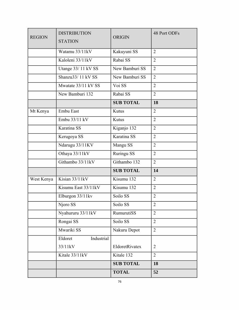
76
REGION DISTRIBUTION
STATION ORIGIN
48 Port ODFs
Watamu 33/11kV Kakuyuni SS 2
Kaloleni 33/11kV Rabai SS 2
Utange 33/ 11 kV SS New Bamburi SS 2
Shanzu33/ 11 kV SS New Bamburi SS 2
Mwatate 33/11 kV SS Voi SS 2
New Bamburi 132 Rabai SS 2
SUB TOTAL 18
Mt Kenya Embu East Kutus 2
Embu 33/11 kV Kutus 2
Karatina SS Kiganjo 132 2
Kerugoya SS Karatina SS 2
Ndarugu 33/11KV Mangu SS 2
Othaya 33/11kV Ruringu SS 2
Githambo 33/11kV Githambo 132 2
SUB TOTAL 14
West Kenya Kisian 33/11kV Kisumu 132 2
Kisumu East 33/11kV Kisumu 132 2
Elburgon 33/11kv Soilo SS 2
Njoro SS Soilo SS 2
Nyahururu 33/11kV RumurutiSS 2
Rongai SS Soilo SS 2
Mwariki SS Nakuru Depot 2
Eldoret Industrial
33/11kV EldoretRivatex 2
Kitale 33/11kV Kitale 132 2
SUB TOTAL 18
TOTAL 52

77
3. Detailed Cable Characteristics
i. General
The ADSS optical cable shall be of non- metallic Aerial type designed for installation on 132 kV
Power transmission lines as well as 66kV/33kV and 11kV distribution lines with minimum span
lengths of 100 mts. The Bidder shall offer ADSS containing 48 Nos. of Single Mode (SM)
optical fibers in conformity with ITU-T recommendations G-652D. The cable shall be designed
to withstand all prevailing environmental conditions including the effects of high electric and
magnetic fields produced by the proximity of live power conductors.
ii. Mechanical and Environmental specifications for 48 core SM (9/125) ADSS fiber
optic cable
The cable shall be constructed from materials which have been technically proven andable to
withstand the electrical and environmental conditions.
Table below gives the desired mechanical and environmental specifications for the ADSS Fiber
Optic Cable for minimum performance characteristics.
Table3.3 mechanical and environmental Specifications for 48 Core SM (9/125) ADSS Fiber
Optic Cable
Table 3-3
ITEM DESCRIPTION MINIMUM REQUIREMENTS TENDERER’S
OFFER
1. Fiber counts 48
2. Minimum Operating Load 6000 N
3. Minimum Bending Radius
Installation
Long Term
20xO.D.
10xO.D.
4. Minimum. Compressive
Loading
4000 N / 10 cm

78
ITEM DESCRIPTION MINIMUM REQUIREMENTS TENDERER’S
OFFER
5. Impact Resistance 4.4 J, 3 x 2 times
6. Twist (Torsion) 10 turns of 180 on
125xO.D.sample, both ways.
7. Storage Temperature Range -50 C to +50 C
8. Operating Temperature
Range
-40 C to +50 C
9. Core Fluid Penetration 1 m sample, 1 m water head for 24
Hrs
10. Distance Between Poles Up to 100M
11. Warranty 15 years
12. UV Resistance
13. Outer Cable Markings Property of Kenya Power &
Lightening Company
14. Packing Rolls for various sections to be
determined by distance between
section poles but not less than
1000M
15. Length marking Every meter
16. Color of Cable Black
17. Performance Allowed attenuation per Km for
the 9/125 micron single mode fiber
optic cable
1) 1310 0.4 db/km
2) 1550 0.3 db/km
18. Fusion splice loss
Maximum allowed loss 0.1db

79
iii. General Specifications for the Optical Distribution Frame (ODF)
Error! Reference source not found. Below gives the general technical specification for the Optical
Distribution Frames.
Table 3-4General Specifications for ODF
ITEM DESCRIPTION MINIMUM REQUIREMENTS TENDERERS
OFFER
1 Fiber optic wall
mounted ODF
Fiber optic patch panel 48 ports
SM wall mounted with enclosure
splice tray cassette,
48 pigtails terminated on FC
connectors
Dust proof housing & lockable
with key
iv. Fitting Materials
All fitting materials shall conform to the approved standards by IEEE1222. The bidder shall
attach type test certificates from the certifying bodies.
v. Applicable Standards
Unless otherwise specified in this specification, all requirements for individual components and
completed cable shall mainly be in accordance with the following standard specifications;
1EEE std 1222, IEC 60794-4, IEC 60793-1, IEC 60793-2, IEC 60794-1, ITU-T G.652D, EIA
492A, EIA 472A, EIA 598or ANSI/EIA 359-A-1985, ISO 9001 and ISO 14001.
3.1.2.3 GUARANTEED TECHNICAL PARTICURLARS AND STATEMENT OF COMPLIANCE
(This section is to be filled and signed by the Manufacturer for all clauses and submitted
together with catalogues, brochures, drawings, and technical data and test reports for tender
evaluation)

80
Table 3-5
DESCRIPTION BIDDER’S OFFER
1. Manufacturer’s Name & Country of
manufacture
2. Type Reference/Model Number of cable
offered
3. Corrosion/ rust free fittings &
components
4. Environmental Conditions that cable can
withstand as per technical specification.
5. International recommended Standards
adhered to.
6. Maximum induction Voltage (kV) cable
can withstand
7. Cable loss per Kilometer (db)
8. List of copies of Type Test Reports
submitted (indicate Test Report Numbers,
Testing Authority and contact addresses)
9. List of Acceptance Tests to be witnessed
by KPLC Engineers at the factory
10. List of catalogues, brochures, technical
data, drawings and customer sales records
submitted to support the offer.
11. Statement of compliance to
specifications & guarantee
..……………………………………………………………………………
Manufacturer’s Name, Signature, Stamp and Date

81

82
3.1.3 FIBER OPTIC TOOLS & TEST EQUIPMENT SPECIFICATIONS
A set of the requisite tools shall be provided with each lot as specified in the schedule of
requirements. The tools shall conform to the minimum requirements below;
3.1.3.1 SPLICING KIT
The splicing kit shall consist of the basic set of implements necessary to carry out a splicing
exercise and shall include the following at the minimum; a fusion type splicing machine,
cleavers, strippers, batteries and power cord. The splicing machine shall be a 4-fiber ribbon
splicer with high versatility. It shall be well suited for FTTXx applications and shall be of robust
construction. Below are the features desired for the splicing machine;
i. Rugged construction providing shock, dust and moisture resistance
ii. Ability to withstand a 30” drop test.
iii. Dual monitor position with automatic image orientation
iv. Automatic arc calibration and ribbon fiber identification
v. Auto-start tube heater
vi. Color LCD display and anti-reflective coating for excellent visibility in bright sunlight
vii. Simultaneous battery charge and splicer operation
viii. Long life battery (up to 90 splice/heat cycles per charge)
ix. Detachable work table incorporated into the transit case
x. Data and video download software and splicer upgrade software to be included;software
upgrades through PC application via the internet
xi. Green friendly – RoHS & WEEE compliant

83
Table 3-6 Technical Specifications for Splicing Machine
S/NO. DESCRIPTION MINIMUM REQUIREMENTS TENDERERS
OFFER
1. Type Fusion Splicer
2. Applicable Fibers Single-mode ITU-T G.652D
3. Fiber Count Single, 2, 4
4. Cladding Diameter 125μm
5. Coating Diameter Ribbon: 0.25mm to 0.4mm; Single:
250μm and 900μm
6. Fiber Cleave Length 10mm
7. Typical Average Splice
Loss
0.05dB with SM, measured by cut-
back method relevant to ITU-T and
IEC standards
8. Splicing Time 20 seconds with standard single-mode
fiber
9. Arc Calibration Method Automatic with option of manual arc
calibration function
10. Splicing Modes 100 preset and user programmable
modes
11. Storage of Splice Result Last 2000 splice results
12. Fiber Display Both X and Y simultaneously with
option of rear monitor display with
automatic image orientation
13. Magnification 90X
14. Viewing Method Dual cameras with 4.1 inch TFT color
LCD monitor with anti-reflective
coating
15. Operating Condition 0 to 5,000m above sea level, 0 to 85%
RH, -10 to 50°C respectively
16. Mechanical Proof Test 1.96 to 2.25N

84
S/NO. DESCRIPTION MINIMUM REQUIREMENTS TENDERERS
OFFER
17. Tube Heater Built-in tube heater with 30 heating
modes complete with auto-start
function
18. Tube Heating Time 50 seconds with FP-5 sleeve, 40
seconds with FP3 (40
19. Protection Sleeve
Length
60mm, 40mm, micro
20. Splice/Heat with
Battery
90 cycles with power save functions
activated
21. Power Supply Auto voltage selection from 100 to
240V AC or 10 to 15V DC
22. Terminals USB 2.0 (USB-B type) for PC
communication
23. Wind Protection Maximum wind velocity of 15m/s. (34
mph)
24. Dimensions 136W x 161D x 143H (mm) / 5.3W x
6.3D x 5.6H (inches)
25. Weight 2.1 kg (4.6 lbs) with AC adapter
3.1.3.2 TERMINATION KIT
The termination kit shall be a standard toolkit that contains a collection of essential tools needed
for termination of Single Mode fiber optic cable of all connector styles (SC, FC,LC& ST). The
case should be a carry like briefcase that is rugged and compact. The case shall be lined with a
foam-padding material that keeps the tools safe, neat and in proper working order.

85
3.1.3.3 FAULT LOCATOR
The fault locator shall be an easy to use device of portable construction. It shall be of high
performance in optical fiber troubleshooting functionalities with capability of locating fiber
breaks and high loss events over long distances. It should be able to detect the fiber break
location and display the results on an LCD screen.6 below gives the minimum requirements for
the desired Fault Locator
Table 3-7 Minimum requirements for Fault Locator
S/No. ITEM
DESCRIPTION
MINIMUM REQUIREMENT TENDERS
OFFER
1. Fiber Type 9/125 µm Single Mode
2. Wavelength 1550±20nm
3. Emitter Type LD
4. Connector Type SC
5. Pulse Width (ns) 10/20/40/80/160/320/640/1280/2560/5
120/12400/24800 (auto-switch)
6. Max Output Power 100 mW
7. Max Measurement
Range
130km
8. Distance Accuracy +/- (0.8m + 0.001% x Distance)
9. Data Storage 999 measurements
10. Event Dead Zone 3 m
11. Power Supply AC/DC adapter & Rechargeable NiHM
Batteries
12. Battery Life 15,000 uses
13. Operating Temp. -10°C to 55°C
14. Storage Temp -20°C to 60°C
15. Humidity <85% (non-condensing)
16. Communication Port USB/Serial
17. Dimension (mm) 190L * 105W * 55H
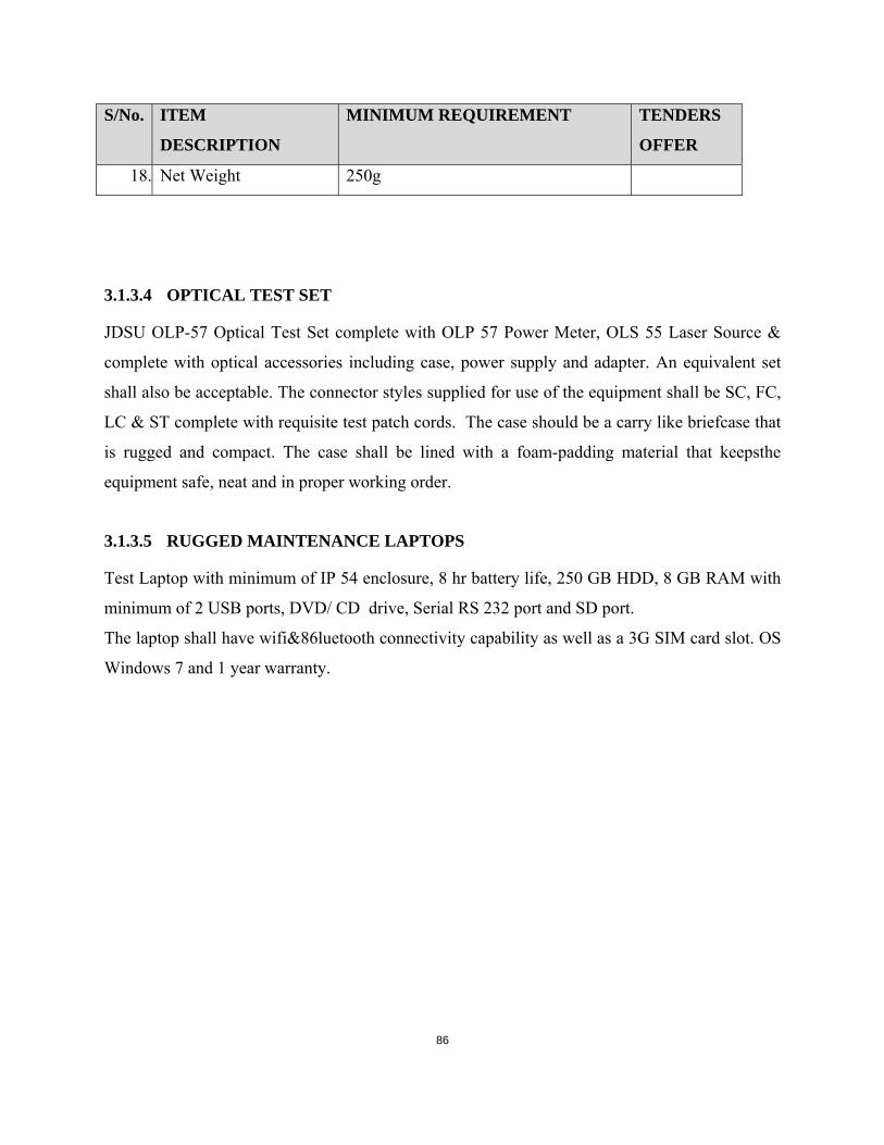
86
S/No. ITEM
DESCRIPTION
MINIMUM REQUIREMENT TENDERS
OFFER
18. Net Weight 250g
3.1.3.4 OPTICAL TEST SET
JDSU OLP-57 Optical Test Set complete with OLP 57 Power Meter, OLS 55 Laser Source &
complete with optical accessories including case, power supply and adapter. An equivalent set
shall also be acceptable. The connector styles supplied for use of the equipment shall be SC, FC,
LC & ST complete with requisite test patch cords. The case should be a carry like briefcase that
is rugged and compact. The case shall be lined with a foam-padding material that keepsthe
equipment safe, neat and in proper working order.
3.1.3.5 RUGGED MAINTENANCE LAPTOPS
Test Laptop with minimum of IP 54 enclosure, 8 hr battery life, 250 GB HDD, 8 GB RAM with
minimum of 2 USB ports, DVD/ CD drive, Serial RS 232 port and SD port.
The laptop shall have wifi&86luetooth connectivity capability as well as a 3G SIM card slot. OS
Windows 7 and 1 year warranty.

87
3.1.4 THE FIBER OPTIC TERMINAL EQUIPMENT SPECIFICATIONS
3.1.4.1 INTRODUCTION
The fiber optic terminal equipment shall be based on user requirement and shall comprise of
either switches or multiplexers.
Table 7 below gives direction of the equipment required at each node.
Table 3-8 Proposed Link Equipment
DISTRIBUTION SUBSTATIONS
Station Link End SS Proposed Link Equipment
NAIROBI REGION – STATIONS CONNECTED TO NCC
1. Donholm 11kV NAIROBI SOUTH Switches
2. Industrial 66/11kV NAIROBI SOUTH Switches
3. Karen 66/11kV NAIROBI WEST Multiplexer
4. Limuru 66/11kV NAIROBI NORTH Switches
5. Athi River 33/11kV EMBAKASSI Multiplexer
6. Machakos 33/11kV EMBAKASSI Multiplexer
7. Nairobi Airport 66/11kV EMBAKASSI Switches
8. Nyaga 33/11kV RUIRU SS Switches
9. Muthurwa (new) NAIROBI SOUTH Switches
10. EPZ ATHI RIVER SS Switches
COAST REGION – STATIONS CONNECTED TO RABAI RCC

88
10. Msambweni 33/ 11kV Mwabungo 33/11kV Switches
11. Mwabungo 33/11kV GALU SS Switches
12. Kanamai 33/11 kV SS NEW BAMBURI Switches
13. Watamu 33/11kV KAKUYUNI SS Switches
14. Kaloleni 33/11kV RABAI SS Switches
15. Malindi 33/11kV KAKUYUNI SS Multiplexer
16. Utange 33/ 11 kV SS NEW BAMBURI Switches
17. Shanzu 33/11kV NEW BAMBURI Switches
18. Mwatate 33/11 kV SS VOI SS Switches
19. NEW BAMBURI RABAI SS Multiplexer
MT KENYA REGION - STATIONS CONNECTED TO KIGANJO RCC
19.
.
Embu East SS KUTUS SS Switches
20. Embu 33/11kV KUTUS SS Switches
21. Karatina SS KIGANJO 132 Switches
22. Kerugoya SS KARATINA SS Switches
23. Ndarugu 33/11KV MANGU SS Switches
24. Meru 33/11kV MERU 132 Switches
25. Othaya 33/11kV RURINGU SS Switches
26. Githambo 33/11kV RURINGU SS Switches
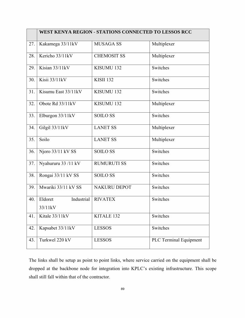
89
WEST KENYA REGION - STATIONS CONNECTED TO LESSOS RCC
27. Kakamega 33/11kV MUSAGA SS Multiplexer
28. Kericho 33/11kV CHEMOSIT SS Multiplexer
29. Kisian 33/11kV KISUMU 132 Switches
30. Kisii 33/11kV KISII 132 Switches
31. Kisumu East 33/11kV KISUMU 132 Switches
32. Obote Rd 33/11kV KISUMU 132 Multiplexer
33. Elburgon 33/11kV SOILO SS Switches
34. Gilgil 33/11kV LANET SS Multiplexer
35. Soilo LANET SS Multiplexer
36. Njoro 33/11 kV SS SOILO SS Switches
37. Nyahururu 33 /11 kV RUMURUTI SS Switches
38. Rongai 33/11 kV SS SOILO SS Switches
39. Mwariki 33/11 kV SS NAKURU DEPOT Switches
40. Eldoret Industrial
33/11kV
RIVATEX Switches
41. Kitale 33/11kV KITALE 132 Switches
42. Kapsabet 33/11kV LESSOS Switches
43. Turkwel 220 kV LESSOS PLC Terminal Equipment
The links shall be setup as point to point links, where service carried on the equipment shall be
dropped at the backbone node for integration into KPLC’s existing infrastructure. This scope
shall still fall within that of the contractor.
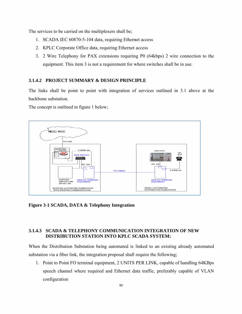
The servi
1. S
2. K
3. 2
eq
3.1.4.2
The link
backbone
The conc
Figure 3
3.1.4.3
When th
substatio
1. P
sp
co
ices to be ca
CADA IEC
KPLC Corpo
Wire Telep
quipment. T
PROJECT
ks shall be
e substation.
cept is outlin
-1 SCADA,
SCADA & DISTRIBU
he Distributio
n via a fiber
oint to Point
peech chann
onfiguration
arried on the
60870-5-10
rate Office d
phony for PA
his item 3 is
SUMMAR
point to po
.
ned in figure
, DATA & T
TELEPHOUTION STA
on Substatio
r link, the int
t FO termina
nel where re
n
multiplexer
04 data, requ
data, requirin
AX extensio
s not a requir
RY & DESIG
oint with int
1 below;
Telephony I
ONY COMMATION INTO
on being aut
tegration pro
al equipmen
equired and
90
rs shall be;
uiring Ethern
ng Ethernet a
ons requirin
rement for w
GN PRINCI
tegration of
Integration
MUNICATIO KPLC SC
tomated is l
oposal shall r
t, 2 UNITS P
Ethernet da
net access
access
ng P0 (64kbp
where switch
IPLE
f services o
ION INTEGCADA SYS
linked to an
require the f
PER LINK,
ata traffic, p
ps) 2 wire c
hes shall be i
outlined in 3
GRATION OTEM:
n existing al
following;
capable of h
preferably ca
connection t
in use.
3.1 above a
OF NEW
lready autom
handling 64K
apable of V
to the
at the
mated
KBps
VLAN

91
2. A Ruggedcom or equivalent switch at the existing station
3. All necessary accessories & configuration to achieve the link above in fig 1 above.
3.1.4.4 MULTIPLEXER REQUIREMENTS
Table 3-9 Guaranteed technical particulars (multiplexer)
Minimum Requirements Tendered Offer
Make and Model
Equipment Manufacturer
Tenderer to state
Make and Model
Tenderer to state
A. General Features
Four E1 data ports
Four Ethernet ports
Access units for P0 (64kBps), n x P0 ,E1 or n x E1 services.
Can support Drop/Insert features in/out of the P0 &E1
Can support E1 to E1 channel pass through and n x P0 cross
connect between the E1’s
STM-1 Optical aggregate up to 140 MBps
B. Interfaces
Data Rate 2.048 Mbps on E1 on 4 wire Krone Block or RJ
11 connector
Connector RJ-45 for Ethernet connectivity upto 100Mbps
per port with VLAN configuration capability
FXO & FXS for 2 wire P0 (64Kbps) telephony extension
from PAX
E1 interface complies with: ITU G.703, G.704, G.706,
G.732 for TDM & SDH compatibles
Complies ITU Jitter G.823 & G.824
Ethernet Range of up to 300 feet
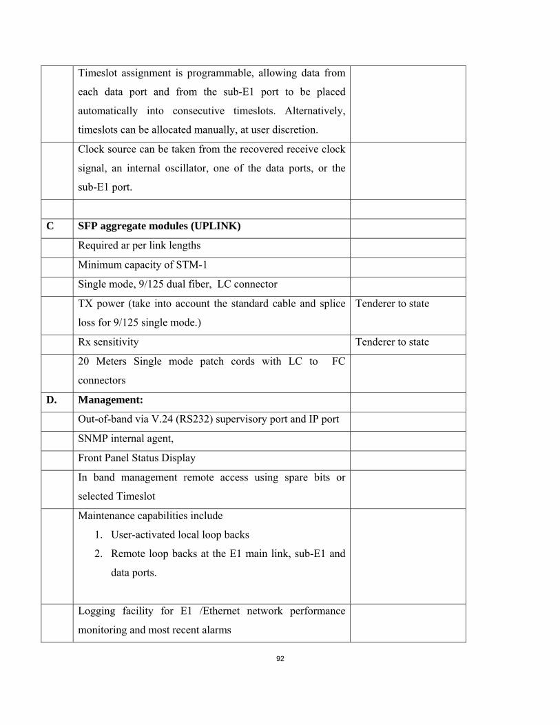
92
Timeslot assignment is programmable, allowing data from
each data port and from the sub-E1 port to be placed
automatically into consecutive timeslots. Alternatively,
timeslots can be allocated manually, at user discretion.
Clock source can be taken from the recovered receive clock
signal, an internal oscillator, one of the data ports, or the
sub-E1 port.
C SFP aggregate modules (UPLINK)
Required ar per link lengths
Minimum capacity of STM-1
Single mode, 9/125 dual fiber, LC connector
TX power (take into account the standard cable and splice
loss for 9/125 single mode.)
Tenderer to state
Rx sensitivity Tenderer to state
20 Meters Single mode patch cords with LC to FC
connectors
D. Management:
Out-of-band via V.24 (RS232) supervisory port and IP port
SNMP internal agent,
Front Panel Status Display
In band management remote access using spare bits or
selected Timeslot
Maintenance capabilities include
1. User-activated local loop backs
2. Remote loop backs at the E1 main link, sub-E1 and
data ports.
Logging facility for E1 /Ethernet network performance
monitoring and most recent alarms

93
Alarm mask configurable for any alarm
E. Power Source
Equipment shall be capable of being supplied through 240
Volts AC and -48Volts DC
Power Consumption by the Multiplexers Tenderers to state
F. 3) Other requirements
Rack Mountable 19 inch with mounting brackets
Height (Tenderers to state)
Depth (Tenderers to state)
Weight (tender to state)
G. Environment
Temperature 5°C to 50°C
Humidity Up to 90%, non-condensing
Altitude up to 3000m ASL
H. Type approval & Warranty
Warranty for 1 year
3.1.4.5 UPLINK SWITCH REQUIREMENTS
Table 3-10 Guaranteed technical particulars (Switch)
Minimum Requirements Tendered Offer
Make and Model
Equipment Manufacturer
Tenderer to state
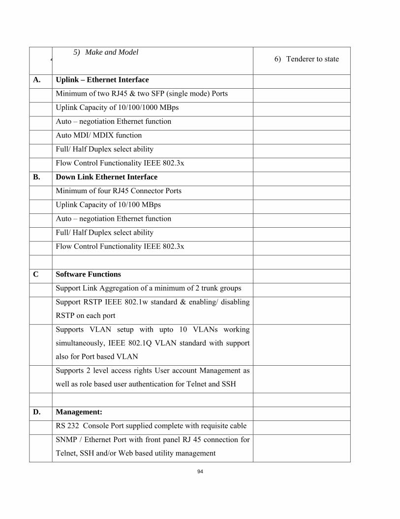
94
45) Make and Model
6) Tenderer to state
A. Uplink – Ethernet Interface
Minimum of two RJ45 & two SFP (single mode) Ports
Uplink Capacity of 10/100/1000 MBps
Auto – negotiation Ethernet function
Auto MDI/ MDIX function
Full/ Half Duplex select ability
Flow Control Functionality IEEE 802.3x
B. Down Link Ethernet Interface
Minimum of four RJ45 Connector Ports
Uplink Capacity of 10/100 MBps
Auto – negotiation Ethernet function
Full/ Half Duplex select ability
Flow Control Functionality IEEE 802.3x
C Software Functions
Support Link Aggregation of a minimum of 2 trunk groups
Support RSTP IEEE 802.1w standard & enabling/ disabling
RSTP on each port
Supports VLAN setup with upto 10 VLANs working
simultaneously, IEEE 802.1Q VLAN standard with support
also for Port based VLAN
Supports 2 level access rights User account Management as
well as role based user authentication for Telnet and SSH
D. Management:
RS 232 Console Port supplied complete with requisite cable
SNMP / Ethernet Port with front panel RJ 45 connection for
Telnet, SSH and/or Web based utility management

95
E. Power Source
Equipment shall be capable of being supplied through 240
Volts AC and -48Volts DC
Power Consumption by the Uplink switches Tenderers to state
F. 7) Other requirements
Rack Mountable 19 inch with mounting brackets
Height (Tenderers to state)
Depth (Tenderers to state)
Weight (tender to state)
20 Meters Single mode patch cords with LC to FC
connectors
Requisite single mode SFP modules to achieve link
G. Environment
Temperature 5°C to 50°C
Humidity Up to 90%, non-condensing
Altitude up to 3000m ASL
H. Type approval & Warranty
Warranty for 1 year
3.1.4.6 STATION SWITCH REQUIREMENTS
The function of this switch shall be purely to connect RTU from distribution station into the
existing SCADA network at the backbone for onward transmittal of both to the relevant RCC

96
Table 3-11
Minimum Requirements Tendered Offer
Make and Model
Equipment Manufacturer
Tenderer to state
Make and Model
Tenderer to state
A. Transmission Rate
Transmission Rate of 10/ 100Mbps
B. Interfaces
Minimum of four RJ45 electrical Interface ports
C. Management:
RS 232 Console Port supplied complete with requisite cable
D. Power Source
Equipment shall be capable of being supplied with 48Volts
DC
Power Consumption by the station switch Tenderers to state
E. Other requirements
35mm DIN rail mounted
F. Environment
Minimum Temperature range of -10°C to 60°C
Minimum of IP 40 Ingress Protection class
Fanless Operating Condition

97
Heavy Duty cast aluminum enclosure or equivalent
G. Type approval & Warranty
Warranty for 1 year
3.1.5 THE FIBER OPTIC CABLE & TERMINAL EQUIPMENT SPARES REQUIREMENT
Making reference to the fiber &terminal equipment installed, the spares required shall be
calculated as follows;
Table 3-12
No Description Quantity %age of Spares Spares List
1 ADSS FO Cable 426 KMS 5% 22 KMS
2 Multiplexers 20 10% 2
3 Uplink Switches 68 10% 7
4 Station Switches 36 10% 4
5 ODFs 52 10% 5
6 FC – LC Patch Cords 52 20% 10
7 SFP Modules (20, 40,
60 & 80 KMS)
2 of each 8
3.1.6 TESTING
Factory Acceptance Tests (FAT) Systems shall pass agreed set out tests before they
may be shipped to site. KPLC shall witness FATs unless he waives this in writing.
FAT preparation costs shall be borne by contractor except transport and
accommodation. FAT shall be carried by two KPLC staff for 5 days.
Site Acceptance Tests (SAT) Systems shall pass agreed set out tests before they may
be put into operation and before they are Taken Over

98
The System will be accepted by KPLC if both:
The System and all items of equipment have successfully completed all the specified tests
All failures, problems and reservations noted during the tests have been corrected to the
satisfaction of KPLC.
If either of these conditions has not been complied with, then the necessary corrective action
shall be agreed between the Contractor and KPLC.
3.1.7 TRAINING
The Contractor shall provide 2 weeks training for four KPLC staff at the supplier’s
manufacturing premises on each Telecommunication type of equipment supplied and on site
during installation works. All training costs shall be borne by Contractor except travel to
manufacturers place and accommodation which shall be borne by KPLC. The scope of each
service shall be given. The training content shall be subject to approval of the project Manager.
3.2 RADIOS
3.2.1 THE TECHNICAL SPECIFICATIONS
Technical specifications describe the basic requirements for goods. In addition to the information
and documentation in the Tender Document regarding the technical aspects of this tender, all
Tenderers shall comply with the following -
3.2.1.1 GENERAL REQUIREMENTS
i. Technical documentation shall be in English language. The specific items on offer shall be
marked clearly for the goods they intend to supply.

99
ii. The Tenderer shall submit the Schedule of Guaranteed Technical Particulars (GTP)
completed by the Manufacturer. In submitting the GTP, cross-references should be made
to the documents submitted.
iii. Deviations from the tender specifications, if any, shall be explained in detail in writing,
with supporting data including calculation sheets, detailed drawings and certified test
reports and submitted together with the Tender. In submitting the deviations, cross-
references should be made to the documents submitted. Kenya Power reserves the right to
reject the goods if such deviations shall be found critical to the use and operation of the
goods.
iv. Detailed contact information including title, e-mail, facsimile, telephone or any other form
of acceptable communication of the testing and standards body used shall be provided.
v. Where Type Test Certificates and their Reports and or Test Certificates and their Reports
are translated into English, all pages of the translations must be signed and stamped by the
testing authority.
vi. A Copy of the manufacturer’s valid quality management system certification i.e. ISO 9001
shall be submitted for evaluation. For locally manufactured goods this requirement is not
mandatory but all Test Reports and Certificates shall be certified by the Kenya Bureau of
Standard (KEBS) or its appointed agent(s), in which case a letter of Accreditation must be
submitted.
vii. In all cases where the level of galvanizing and painting is not specifically stated in the
detailed Technical Specifications, the general requirement shall be for a uniform coating
of thickness not less than 80 microns.
viii. Suppliers are required to provide information on proper representative(s) and or workshop
for back-up service and or repair and maintenance including their names, telephone,
facsimile, e-mail, physical and postal addresses, along with their offers.
3.2.1.2 DIRECT REPLACEMENTS
These radios shall be for direct replacement of existing equipment’s which has been vandalized,
burnt or damaged in any way and shall be mounted on existing cabinets.

100
3.2.1.2.1 The supplier shall install, test and commission the supplied radios
3.2.1.2.2 The radios shall be vendor and type specific to achieve compatibility.
MDS SD4 remote radios shall be used.
Specification shall include:
i. General
a. Frequency Bands: 330 to 400 MHz
b. Data Rate: 9600 bps @ 12.5 kHz Channel Spacing
c. Frequency Programmability: 6.25 kHz increments
d. Operational Modes: Simplex, half-duplex
e. Modulation: Digital / CPFSK
ii. Transmitter
a. Frequency Stability: +/- 0.00015% 1.5 ppm
b. Carrier Power: 0.1 to 5 Watts Programmable
c. Carrier Power Accuracy: Normal +/-1.5 dB
d. Duty Cycle: Continuous
e. Output Impedance: 50 Ohm
iii. Interfaces
a. Serial COM1: RS-232, DB-9
b. Serial COM2: RS-232, RS-485 DB-9
c. Ethernet: 10/100 BaseT, RJ 45
d. Antenna: TNC Female
iv. Receiver
a. Type: Double Conversion Super heterodyne
b. Bit Error Rate: BER 1x10⁻⁶ @ -112 dBm Typical
c. Frequency Stability: +/- 0.00005% (0.5 ppm)
d. Adjacent Channel (EIA): 60 dB nominal

101
3.2.1.3 Radio Details
Table 3-13 Radio Details
Site Frequency Qty
Steel Billets 335-345 MHZ 1
Kikuyu 360-370 MHZ 1
3.2.2 NEW INSTALLATIONS
3.2.2.1 The supplier shall deliver, install and commission point to point radios as specified in this documents.
3.2.2.2 The supplier shall carry out radio path propagation profiling, determining the optimal performance. Details about radio equipments, antenna size, and performance and availability calculations shall be submitted.
3.2.2.3 The supplier shall construct Communication towers at sites described in the bill of quantities.
3.2.2.4 Radio Detailed specifications
i. Architecture: Small Form Factor ODU Unit with embedded antenna and Connectorized
for External Antenna
ii. IDU to ODU Interface: Enhanced Outdoor CAT - 5e cable; Maximum cable length: 100
m
iii. Capacity: 50Mbps aggregate Ethernet net throughput and up to 2 E1s / T1, minimum.
iv. Range: Up to 60 km minimum
v. Encryption: AES 128
vi. VLAN: Supported
vii. Band: 5.9 GHz Universal 5.730 - 5.950 GHz
viii. Safety: ETSI EN/IEC 60950 -1, EN/IEC 60950 - 22
ix. EMC: ETSI EN 300 386, EN 301 489 - 1, EN 301 489 - 4
x. Operating Temperatures - 35°C - 60°C / - 31°F – 140°F
xi. Power: 48 VDC, Power Feeding: Power provided over ODU - IDU cable

102
3.2.2.5 Link Details
Table 3-14 Link Details
Link Site1 Tower, Site2 Tower
Lot Marura-
Naivasha
Naivasha Existing, 20m Marura 20m
Kihoto-
Naivasha
Naivasha Existing, 20m Kihoto 20m
Chemosit-
Mogosiek
Chemosit
30m Mogogosiek 20m
Chemosit-
Sotik
Chemosit 30m Sotik 20m
Cheptulu-
Kakamega
Kakamega 20m Cheptulu 20m
3.2.2.6 Enclosures
3.2.2.6.1
All equipment shall be housed in single sheet steel cubicles segregated into compartments
by sheet steel separators, and of height of 9 U and width of 840mm. The cubicle shall be wall
mounted.
3.2.2.6.2
Cubicles shall have a hinged front cover with locking facilities, giving full
access to all components and cable connections. The front cover shall be solid and transparent.
3.2.2.6.3
The cubicles shall satisfy the requirements of corrosion protection as specified and shall be
ventilated and protected to class IP42.

103
3.2.2.6.4
Where ventilation openings are provided these shall be fitted with drip-proof louvers and fine
mesh wire or perforated screens to exclude small insects and vermin.
3.2.2.6.5
A gland plate shall be provided sufficient for all incoming and outgoing cables including spare
capacity
3.2.3 COMMUNICATION TOWERS
3.2.3.1 TECHNICAL SPECIFICATIONS
Technical specifications describe the basic requirements for goods. In addition to the information
and documentation in the Tender Document regarding the technical aspects of this tender, all
Tenderers shall comply with the following -
3.2.3.2 Part A - General Requirements
1. Technical documentation shall be in English language. The specific items on offer shall
be marked clearly for the goods they intend to supply.
2. Deviations from the basic requirements, if any, shall be explained in detail in writing with
the offer, with supporting data including calculation sheets, detailed drawings and certified test
reports. The Procuring Entity reserves the right to reject the goods if such deviations shall be
found critical to the use and operation of the goods.
3. The Supplier shall submit a commentary on the Guaranteed Technical Particulars (GTP)
as well as a Statement of Compliance to Technical Specifications. In submitting the GTP and
Statement of Compliance, the Suppliers and or Manufacturers should provide cross-references to
the documents submitted.

104
4. The Statement of Compliance shall be in table form, and shall cover in detail, all clauses
of the specification(s).
5. Detailed contact information including title, e-mail, facsimile, telephone or any other
form of acceptable communication of the testing and standards body used shall be provided.
6. Where Type Test Certificates and their Reports and or Test certificates and their Reports
are translated into English, all pages of the translations must be signed and stamped by the
testing authority.
7. The Manufacturer’s Declaration of Conformity to reference standards and copies of
quality management certifications including valid ISO 9001: 2000 shall be submitted for
evaluation. For locally manufactured goods this requirement is not mandatory but all Test
Reports and Certificates shall be certified by KEBS or it’s appointed agent(s), in which case a
letter of Accreditation will be required.
8. In all cases where the level of galvanizing and painting is not specifically stated in the detailed
Technical Specifications, the general requirement shall be for a uniform coating of thickness not
less than 80 microns.
9. Suppliers are required to provide information on proper representative(s) and or
workshop for back-up service and or repair and maintenance including their names,
telephone, facsimile, e-mail, physical and postal addresses, along with their offers.
10. Suppliers shall be aware of requirements and regulations guiding Design, Supply and
installation of radio masts by the Communication Commission of Kenya and relevant
local authorities.
11. It shall be the responsibility of the suppliers to obtain necessary permits and approval from
local authorities and the regulator, Communication Commission of Kenya.
12. The supplier shall submit detailed drawings for approval.
Detailed Technical Specifications for the goods appear hereafter.
3.2.3.3 Part B – Detailed Technical Specifications
1.0 The Towers shall be designed to withstand basic operational wind speed of 40 m/s
2.0 Maximum deflection at the highest position under the most adverse loading of is 60% of
the maxim allowable limit of 0.5 degrees.

105
3.0 The tower elements will primarily consist of angular members with optimized and
manufacturing and fabrication efficiencies and speeds. A working/service platform shall
be provided.
4.0 Bolts and nuts shall be manufactured with high strength A 325 according to ASTM.
5.0 The following accessories and safety equipment shall be provided with the towers;
5.1) A lighting arrestor of 1.5 meter length for installation at the top of the
tower.
5.2) 3” diameter 3 meter long poles for mounting bracket sets
5.3) Suitably designed climbing ladder
6.0 Tower earthings system shall be to design specifications and shall conform to
international standards and IEEE specifications to earthing telecommunications masts.
7.0 Aviation warning Lights (AWL) using 240 VAC shall be 100,000 hours life and
necessary cables for lighting from substation building shall be provided.
8.0 The towers are to be installed in various parts of the country and foundation designs shall
take into consideration terrain categories and quote appropriately.
9.0 The tower shall be designed to sustain a wind loading on tower equipment as required by
BS specification CP3# Chapter V: part 2
10.0 The tower shall be designed and constructed to a foundation structure as required by BS
specification BS 8110
11.0 All welding and steel inspection processes are backed by AISC Certification/or
internationally accepted standard and ISO 9001
12.0 Towers should be designed to meet or exceed the latest EIA/TIA code requirements.
13.0 Towers should be fabricated in a factory using fully automated machines.

106
Table 3-15
Minimum Requirement Tenderers
offer
1. Towers MUST be triangular. Towers of exceptional strength, ease of
implementation, and low maintenance
2. All welding and steel inspection processes are backed by AISC Certification and
ISO 9001.
3. Every product should be designed to meet or exceed the latest EIA/TIA code
requirements.
4. The steel used in the manufacture of the towers should be of grade 350WA and the
bolts should be of grade 8.8.
5. Tower sections should be supplied galvanized. The galvanizing thickness should be
equal or less than 5mm.
6. Assembles with basic tools (such as pulley block, rope, torque wrench)—no cranes
or any other heavy or specialized equipment required.
10. Should have no welding, no drilling—all Tower connections are bolted.
11. Modular design with 2-4 m legs.
12. For 30 m Tower height – in 2-4 m increments up to the end of the tapered section,
thereafter in 2-4 m increments up to the Top.
13. For 15 and 20 Meter Tower height - in 2-4 Meters increment parallel sections
Parallel Light Weight Tower (15-30m Tower):
The parallel light weight tower has the following physical properties.
1. height -15-30m
2. parallel section MUST be -15 -30m
3. parallel face width- 1.5 m
4. Tower heights- in 2-4 m increments up to top

107
Foundation Designs
The table below gives approximate standard foundation design quantities for various
tower heights;
Tower Height Concrete volume Rebar Excavation Backfill
(m) ( m³ ) (kg) ( m³ ) ( m³)
15 3.2 220 9.8 7.3
20 3.6 250 11.7 7.6
30 6.6 500 22 14.6
Antenna Loading Capacity
Basic wind speed 40 m/s
Terrain category 2
Altitude 0 m
False datum 0 m
Antenna loading 5.4 m² over the top 4.5m of the Tower

108
CHAPTER FOUR
4 48 VDC CHARGERS AND BATTERIES THE TECHNICAL SPECIFICATIONS
Technical specifications describe the basic requirements for goods. In addition to the information
and documentation in the Tender Document regarding the technical aspects of this tender, all
Tenderers shall comply with the following -
4.1 GENERAL REQUIREMENTS
Technical documentation shall be in English language. The specific items on offer shall be
marked clearly for the goods they intend to supply.
The Tenderer shall submit the Schedule of Guaranteed Technical Particulars (GTP) completed
by the Manufacturer. In submitting the GTP, cross-references should be made to the documents
submitted.
Deviations from the tender specifications, if any, shall be explained in detail in writing, with
supporting data including calculation sheets, detailed drawings and certified test reports and
submitted together with the Tender. In submitting the deviations, cross-references should be
made to the documents submitted. Kenya Power reserves the right to reject the goods if such
deviations shall be found critical to the use and operation of the goods.
Detailed contact information including title, e-mail, facsimile, telephone or any other form of
acceptable communication of the testing and standards body used shall be provided.
Where Type Test Certificates and their Reports and or Test Certificates and their Reports are
translated into English, all pages of the translations must be signed and stamped by the testing
authority.
A Copy of the manufacturer’s valid quality management system certification i.e. ISO 9001 shall
be submitted for evaluation. For locally manufactured goods this requirement is not mandatory
109
but all Test Reports and Certificates shall be certified by the Kenya Bureau of Standard (KEBS)
or its appointed agent(s), in which case a letter of Accreditation must be submitted.
In all cases where the level of galvanizing and painting is not specifically stated in the detailed
Technical Specifications, the general requirement shall be for a uniform coating of thickness not
less than 80 microns.
Suppliers are required to provide information on proper representative(s) and or workshop for
back-up service and or repair and maintenance including their names, telephone, facsimile, e-
mail, physical and postal addresses, along with their offers.
4.2 DETAILED TECHNICAL SPECIFICATIONS
4.2.1 GENERAL REMARKS
Kenya Power intends to procure 48 VDC Supplies for its 45 critical telecommunication sites
across the country to meet growing demand, increase standby time, reliability, and effective
remote monitoring.
4.2.2 SCOPE
This specification gives minimum requirements for 48 VDC Chargers, Batteries and DC control
and distribution Boards, to be supplied at various telecommunications sites spread across the
country. This shall include Design, installation works, testing, and commissioning works.
The supplier may request, at his own cost, to conduct a site survey to ascertain any details that
4.2.3 RECTIFIER/ BATTERY CHARGER
4.2.3.1 General
A 100% duty charger, having boost and float capabilities shall be supplied.
The battery charger is to be solid state, SCR technology or swicthmode technology,
microprocessor controlled. It must be designed to float or equalize batteries using a constant
voltage, current limiting logic. Timer and controls must be static.

110
Each charger unit shall be capable of supplying the initial charging requirements, boost charging
the battery subsequent to an emergency discharge and supplying the maximum load whilst on
float. The batteries shall be recharged within 12 hours to a fully charged condition.
The charger shall be equipped with a “Surveillance” device, this device shall be fed by its own
DC-DC supply coming from the battery and operate with a different firmware than the main
controller. The “Surveillance” device shall communicate with the control board through an
internal communication bus network, should any of the two devices fail, the healthy circuit shall
de-energize a form ‘C’ contact for immediate intervention.
The charger shall have a built-in, dual Electronic Low Voltage disconnect device (ELVD) for
battery protection.
The charger shall have an option to connect at least two Low Voltage Disconnect contactors of
upto 1600A.
Blocking diode with full redundancy shall be provided in the output circuit of each
Charger to prevent current flow from the D.C. Battery into the Charger.
Have RFI- Interference protection at least equal to mode "N" according to DIN VDE 0875.
If required, 48-24VDC converter shall be integrated into the charger and shall be possible to
manage through the controller. The capacity shall be10A. The 24VDC output shall clearly be
marked on the D.C distribution board. The 48 VDC output provision shall still be maintained
through spare capacity as required elsewhere in this specification.
The rectifier/battery charger may be supplied by single phase A.C input upto 50A DC
output.100ADC and 200ADC output, shall have three phase AC input.
4.2.3.2 The Controller
The controller shall:
Be hot swappable.

111
Have minimum and maximum operating voltages as 20VDC and 70VDC respectively to ensure
it functions correctly under extreme conditions.
Be capable to monitor, manage and utilise at least two battery sets.
Be capable to control at least 35 rectifier modules.
Have LCD display for alarms/events with date and time stamp, Input AC Voltage and current
measurements without external equipment, DC Voltage and current measurements for battery
and Load.
Have non-volatile storage of alarms/events with time and date stamp, exceeding 350 entries.
Control and provide individual rectifier information.
Shall have inbuilt, automatic battery testing capability without disconnecting the load. Tests
shall include but not limited to:
-Constant current, capacity, real load, and time based battery tests.
Natural battery test (using the opportunity of a mains failure)
Shall have configurable charging functions including:
-Float charge
-Boost charge
-Equalize
-Event controlled charge
Shall have the following supervision functions:
-Back-up time
-Middle point voltage supervision
-String current comparison
-Block voltage measurement
-Redundancy and power capacity supervision

112
4.2.3.3 Rectifiers
The rectifiers units shall have:
Modular construction, hot swappable and easy to remove/replace from front of the cubicle.
A means of isolating from the main system shall be independently protected from a.c input
surges of 6000V at 3000A per IEEE 587 standard. Surge protection assures performance under
adverse conditions.
Automatic load sharing ensuring equal power distribution from no load to full load between
modules in parallel applications, to within +-5%.
Active power-factor correction shall be greater than 0.99.
Shall have output current indication on the front.
Input surge protection device shall be located in a convenient place, at the back plane, to ensure
ease of access and replacement.
4.2.3.4 Output Voltage
Output voltage to be temperature compensated. Maximum allowed voltage is 59VDC and the
minimum allowed voltage is 47 VDC.
Have the possibility to adjust and set the charger output voltage and current limit values
separately for each operating mode of the charger. The adjustable range shall be the limits of
maximum and minimum outputs.
Soft start feature shall be provided to build up the voltage to the set value slowly within fifteen
seconds.
The chargers shall have load limiters, which shall cause, when the voltage control is in automatic
mode, a gradual lowering of the output voltage when the DC load current exceeds the load
limiter setting of the Charger.
The load limiter characteristic shall be such that any sustained overload or short circuit in DC
system shall neither damage the Charger nor shall it cause blowing of any of the charger fuses.

113
The Charger shall not trip on overload or external short circuit. After clearance of fault, the
Charger voltage shall build up automatically when working in automatic mode.
During Float charging, the Charger output voltage shall remain within ±0.5% of the set value for
AC input voltage variation of 230 +10%, -15% frequency variation of ±5%, a combined voltage
and frequency (absolute sum) variation of 10% and a continuous DC load variation from 5% to
full load.
Energizing the Charger with fully charged battery connected plus 10% load shall not result in
output voltage greater than 110% of the voltage setting. Time taken to stabilize, to within the
specified limits in clause 3.4 (e), shall be less than five seconds.
All potentiometers shall be electronically locked to contain the various parameters within
allowable limits even if the setting position of potentiometers is changed to extreme positions.
4.2.3.5 Charging
The charging process shall be constant voltage with float and boost charging capabilities.
Equalize circuit must be embedded as such it can be activated or deactivated as per the battery
specifications.
The charging process shall be automatic and microprocessor controlled.
The charger shall automatically switch into the boost charging mode when the battery has
discharged below a preset value.
During Boost charging, the Battery Chargers shall operate on constant current mode with
maximum current limiter setting (When automatic regulator is in service).
Equalize commands and timing must be available via the communication port and must also be
available in manual mode.
Automatic equalize activation modes must be based on: Time, low voltage, charger start, AC
fail, AH count, with an adjustable delay of up to 72 hours.

114
Automatic equalize termination modes must be based on: Time, battery voltage, charger current,
AH counts and temperature. All automatic modes must be protected by a timer.
The charger shall be equipped with two additional charge modes: Automatic antidepressant
equalize mode for Ni-Cd batteries and a fully manual mode for the commissioning charge
(constant current mode) of batteries.
Full charge detection shall be done accurately by monitoring change in battery voltage and
change in temperature.
Have operating characteristic in accordance with DIN 41772/DIN 41773. The charging
characteristic shall be to the approval by Kenya Power.
However, the battery manufacturers recommendations for float/trickle, equalizing and boost
charging shall be taken into consideration.
4.2.3.6 DC regulation
Static regulation is to be (+/-) 0.5% RMS voltage from 0 to 100 % full load having a +10 % / -
12% input voltage variation (as per NEMA PE-5) and +/- 5% frequency.
4.2.3.7 Output current
Charger shall be capable of providing 100 % of rated output current on a permanent basis.
4.2.3.8 Ripple voltage
Ripple is to be limited to 30mVrms for 48VDC systems, when connected to a resistive load (not
to a battery). The battery charger must be able to operate without being connected to a battery.

115
4.2.3.9 Redundancy Design
4.2.3.9.1 Dual charger, single battery system
Charging system shall have two identical chargers. Both chargers shall be of identical design and
rating capable of parallel operation.
Forced current sharing must be provided with no common circuit or control wiring between
chargers to prevent One Common Point Failure.
The chargers and battery sets shall be interconnected as shown in fig. 3.9.1.1
Figure 4-1 Fig. 4.2.3.9.1:
Normal operation shall be MCB A, MCB B, MCB1 closed.
In the event of any charger trip, both D.C.D.B shall be energized by the other charger. To offer
operational redundancy, the charger shall meet the load requirements if one rectifier fails.
Therefore, each Changer unit shall have N+1 rectifier units, where N is the number that meets
the Load requirements. This shall be irrespective of loading calculations. The number of
LOADS LOADS
MCB A
CHARGER A
BATTERY A
CHARGER B
DIST. BOARD A DIST. BOARD B
MCB B
MCB1

116
rectifiers per charger shall be determined by the total loading per site as shown in the schedule of
requirements and shall be rounded up to the nearest unit.
There shall be at least one spare rectifier slot for a two rectifier charger and minimum two spare
slots for changers with more rectifier units. The spare slots shall be fully equipped.
a) The battery bank shall be designed for full load standby as specified elsewhere
in this specification.
4.2.3.9.2 Dual Charger, Dual Battery System
Charging system shall have two identical chargers with specifications as indicated in 3.9.1
a) Each charger unit shall be capable of supplying the initial charging
requirements, boost charging the battery subsequent to an emergency
discharge and supplying the maximum load whilst on float.
b) The chargers and their respective battery sets shall be interconnected to
ensure full redundancy as shown in fig. 4.2.3.9.2:
Figure 4-2 LOADS
BATTERY A BATTERY B
MCB1 MCB 3
MCB 2
CHARGER A CHARGER B
LOADS
DIST. BOARD A DIST. BOARD B
DC TIE MCB
MCB A MCB B
MCB4 MCB5

117
c) The chargers shall be interlocked so that only one battery may be boost
charged at any time.
d) Each charger shall connect to its own DC distribution Board with capacity to
connect all loads and spares as specified elsewhere in this specification.
e) The distribution boards shall be interconnected via a DC tie MCB.
f) Each charger shall have its output protected by an MCB, (MCB A & MCB
B) which shall trip in event of a major internal fault in the charger.
g) The normal operation shall be MCBA, MCB B, MCB 1, MCB
2,MCB4,MCB5 shall be closed and MCB3, DC tie MCB shall be open. In
event of charger trip, the DC tie MCB shall close automatically, followed by
paralleling of the battery banks, (MCB3 close) without load interruption.
This operation shall have a manual bypass. The tripping of MCB3 shall
generate a critical alarm in the controller and also pick a dry alarm contact.
h) In event of a fault in a battery bank, its MCB (MCB1 or MCB2) shall trip
and MCB3 shall close. Each trip shall generate a battery faulty alarm and
pick a dry alarm contact.
The chargers shall have Event controlled charge such that the event in cl 4.6.2, i shall set a
charge mode to accommodate two battery banks.
i) Each charger shall be capable to charge and monitor the two battery sets in
parallel.
j) Rectifier spare capacity shall be as spelled in cl. 4.9.1 (a) for each charger.
k) Each battery bank shall be designed for full load standby as specified
elsewhere in this specification.
l) The supplier may submit design proposals, showing how to achieve the
required redundancy for both systems.
118
4.2.3.10 Operating tolerances
Operating temperature -0ºC to +50ºC, indoors.
Relative humidity 95% without condensation
Operating altitude to 3300 feet with no de-rating
Input A.C supply shall be 230V, 50Hz for single phase and 415V, 50 Hz for three phase.
4.2.4 BATTERY
4.2.4.1 Batteries
One set of continuous duty battery with minimum AH capacity as specified in the bill of
quantities for each site, shall be supplied.
Batteries shall be of the Nickel-Cadmium, Free maintenance and suitable for low rate discharge
applications.
A ternary alkaline electrolyte shall be used to increase performance at high temperatures.
The battery shall be designed using cells encased in a common battery module, and connected in
series with intercell connectors. The cells shall be constructed into battery blocks using stainless
steel cradle and fitted with lifting handle to facilitate easy handling and installation.
Terminals shall also be provided to connect to the adjacent modules in series to achieve a
48VDC string. One 48VDC string shall be designed for 100Ah capacity. Several 48VDC strings
may be connected in parallel to achieve the required Ah capacity. Each string shall have a battery
disconnect circuit breaker.
The + ve electrodes shall be made by encapsulating/impregnating active material on nickel-
plated steel grid/perforated strips, which shall form micro porous cavities exposed to the
electrolyte, thus increasing conductivity in order to ensure that the battery is able to perform
reliably over its life.

119
Similarly, the –ve plate shall be made by encapsulating/impregnating active material on both side
of perforated nickel plated steel plates, to ensure mechanical strength throughout the lifespan of
the battery.
+ve and –ve electrodes shall be separated by micro porous separators, which shall maintain
mechanical separation between electrodes, stop migration of the active material, allow
electrolyte permeability and retention over its useful life.
The battery shall have an overall charge efficiency greater than 80%.
The batteries shall have high internal gas recombination efficiency and low gas emissions
exceeding the requirements of IEC 62259, such as to eliminate watering during the entire life
span of the battery. Minimum recombination efficiency shall be 100% at normal operating
conditions.
The battery shall have a built in, low pressure venting system of self-resealing type with
minimum venting pressure of 150PSI. The vent shall have a flame arresting feature.
Construction of cells shall ensure adequate heat dissipation.
a) Batteries shall comply with the performance requirements of IEC 60623, GR-3020,
NEBS Level III, and the environment requirements of GR-3108.
The battery packs shall have a thermal cut-off inside that feeds back to the charger telling it to
stop the charging once the battery has heated up and a voltage sensing circuit.
The cell containers shall be of robust, impact resistant construction in translucent material
permitting visual inspection of electrolyte and shall be having built-in pressure release valves.
The material shall be flame retardant according to UL 94 VO.
Nickel plated copper intercell connectors shall be used for connecting up adjacent cells and rows.
Bolts, nuts and washers shall be nickel-plated steel/stainless steel.

120
All terminals and cell inter-connectors shall be fully insulated or have insulation shrouds.
Terminals and intercell connectors shall be protected and kept clean by a ‘dead top’ in line to EN
50272-2 (safety) with IP2 level.
Separate terminals shall be provided on the end cell for connecting load through
D.C.D.B. and for connecting charger leads. All terminals shall be of suitably sized nickel-plated
steel. Suitable nickel-plated copper lugs shall be provided by the supplier for use of the purchaser
for connecting up the load wiring. All connectors and leads shall be suitable for carrying 30-
minute discharge current continuously and rated for short circuit duty of 4kA for 01 second.
The cell containers shall be marked with maximum and minimum electrolyte levels.
Further, the battery bank terminal cables shall be routed via a double pole wall mounted fuse-
switch, and the fuse shall be selected so as to discriminate for a fault on the d.c. bus. For a case
where the battery shares a cabinet with the charger, the same shall be provided on the cabinet.
Batteries shall be clearly identified by permanent numbering. The following information shall be
provided on a permanent identification plate with each battery block:
(i) Manufacturer’s reference No. & Code
(ii) Year and month of manufacture
(iii) Voltage and nominal capacity at 8 hr. discharge rate.
The manufacturer shall supply a copy of the instruction manual for commissioning & initial
treatment of the battery and maintenance during service with every battery bank supplied.
4.2.4.2 Operating Tolerances
Operating temperature: -20 deg. C to +50 deg. C
Relative humidity 95% without condensation
4.2.4.3 Battery Fuses
The rating of the battery fuses shall be at least twice the rating of the largest d.c. miniature circuit
breaker used in the distribution circuits and shall be so sized that they do not fail through fatigue

121
brought on by normal charge/discharge conditions. The battery shall be protected by fuses
inserted in the connections between the charger and load.
4.2.4.4 Battery Earthing
The batteries shall operate earthed on the positive electrode. Means shall be provided to detect
low insulation resistance of all the wiring connected to the battery by an appropriate earth fault
detection circuit and to give an earth fault alarm.
The earth fault relay shall be equipped with a minimum of three normally opencontacts for local
indication and remote alarm circuits.
4.2.4.5 Battery Accessories
Each battery set shall be provided with the following appropriate accessories:-
-One - cell testing equipment including voltmeter and thermometer.
-One –AC/DC current clamp meter of -+0.025mA accuracy.
-Two - cell bridging connector.
-One - instruction card and record chart.
4.2.4.6 Racks
Suitable corrosion resistant battery racks and cable supports shall be provided ensuring that:
Metallic racks shall be properly earthed.
A minimum floor area is taken up and a ground clearance of 300 mm from the floor is provided.
Racks shall be made of alkali resistant powder coated steel or stainless steel or FRP to ensure
corrosion resistance.
a) Each battery module is readily accessible and can be removed from its position
without having to remove or shift adjacent modules.
b) The supplier shall furnish complete rack drawings showing battery arrangement,
dimensions in respect to available space.
122
4.2.4.6 Safe disposal of unserviceable batteries
The bidder shall have facilities for proper treatment & disposal of used/unserviceable batteries
that are bought back from the users, in line with the environmental protection rules & regulations
of the country.
4.2.5 D.C. CONTROL AND DISTRIBUTION BOARD
The DC Control and distribution board shall be equipped with MCBs.
The equipment shall be capable of carrying, making and breaking the maximum possible fault
current and details of the make-up of this shall be provided. Curves of battery current plotted
against time under short circuit conditions shall be supplied.
Outgoing distribution cables shall be connected directly to the relevant MCB.
Cabling and wiring terminations shall be shrouded to avoid accidental short circuit or earthing of
the battery. PVC insulation shall be used for fuse wiring connections.
Suitable means shall be provided such that, when the charger is operating in float charge mode
and when switching to boost charge mode, the voltage at the outgoing distribution terminals shall
be automatically limited to within the tolerances as specified elsewhere in this Section. This shall
be achieved by the insertion of voltage dropping diodes into the input circuit and the diodes shall
have a rating of at least twice the board's standing load. A minimum of three diode strings
(stages) shall be provided which shall be inserted into the input circuit of DCDB in stages to
provide the range of voltage control in DCDB within limits as specified elsewhere in this section.
It is preferred that during float mode the diode assembly shall not be included in the circuitry. An
alternative method may be used subject to approval by Kenya Power.
Suitable alarm relays shall be provided to monitor at the distribution board both high and low
battery voltages to pre-set values. The relays shall be fitted with variable time delays adjustable
between 0-30 seconds. The relays shall indicate the fault condition locally and shall have two
sets of voltage free contacts for indication to SCADA.

123
4.2.5.1 D.C. Distribution
The panel(s) shall house all distribution necessary for the station d.c. circuits; they shall at least
be of protection class IP41 with self-cooling, Bottom plate of the D.C.D.B. shall be of detachable
type for entry of outgoing feeder cables.
Minimum three spare breakers (10A, 16A, 32A), fully equipped, shall be provided.
The d.c. panels shall have an alarm table aux (sub-panel) for alarm indications such as:
- Lamp test
- supply in feeds off
- D.C. trip (one for all breakers)
In addition, provision for having one general d.c. alarm connected to the alarm panel in the
station control room shall be provided.
D.C. ammeters and voltmeters shall be provided.
4.2.6 METERING AND MONITORING SYSTEM
4.2.6.1 4.2.6.1 Local Access
The controller shall have at least 5 configurable LEDs
The controller shall have an interactive LCD display and protected by a password All voltage
and current readings as well as all alarms and controls status shall be accessed and displayed on
the LCD. In case of AC Fail, LCD display must be operational.
A keypad to program the controller
A buzzer to sound in case of an alarm.
Real time Read / Write communication port shall be supplied to access all setup and status
parameters through:
Web page via local or dynamic IP address
-Fully licensed proprietary software

124
The following shall be available on the controller module, in English:
AC on Green LED;
Common alarm Red LED;
Simultaneous display of rectifier output current and voltage.
Display of charging mode and alarm status.
Display of sequenced event log on LCD: For easier troubleshooting due to an event.
Battery Charge/discharge ammeter/ ampere hour meter.
0-134 months, in one hour increments, automatic/manual equalize timer with elapsed and
remaining equalize time indication
4.2.6.2 Remote Access
It shall be possible to access the charger remotely to read/write configuration parameters
through:
SNMP
Telnet
Modbus TCP/IP
Dial up Modem
A common alarm form C contact must be provided as a backup.
4.2.6.3 Monitoring System
Each alarm must be displayed on an LCD display. Memory chip must keep the last 350
events with a date and time stamp. The log must be accessible for download through
HyperTerminal.
Minimum alarm available for activation shall be:
Rectifier failure
AC fail
High DC volts
Low DC volts
Positive ground fault
Negative ground fault

125
End of discharge
High volts cyclic shutdown
Equalization on
High ripple
Low & High Frequency alarm and shutdown and automatic restart
High & Low charger temperature alarm and cyclic shutdown
Rectifier high current
Rectifier High volt
Rectifier low volt
SNMP traps for alarm remote monitoring
Integrated GSM interface for configurable SMS alerts for alarms.
At least six configurable dry contacts
The following alarms are mandatory to be configured on the dry contacts individually or
as a group:
Battery fuse failure
Battery circuit faulty
Low DC volts
High DC volts
Earth fault –ve.
Mains Failure
Charger trip/ output low
Any critical alarm
Charger shall be also equipped with:
Configurable alarm classification
DC bus voltage measuring device capable of converting the DC bus voltage measuring
range into DC mA range. The DC bus voltage range shall be 0-75V, and the DC mA
range shall be 0-20mA.
Battery imbalance alarm
Battery continuity tester

126
Temperature compensation based on battery temperature
4.2.6.4 PROTECTION
AC and DC surge suppression as per ANSI/IEEE 37.90.1 (SWC)
AC Lightning arrester as per ANSI/IEEE C62.11
AC input circuit breaker c/w with a high DC volts shunt trip and Open circuit form C alarm
contact.
Two (2)-pole DC output circuit breaker.
Two (2)-pole battery maintenance disconnect switch.
High DC voltage shutdown/disconnect
Low DC voltage disconnect for batteries.
All circuit breakers are to be coordinated with the AC input, battery and rectifier short circuit
capabilities. (Specify the KA rating of each)
4.2.7 ENCLOSURE
All equipment, in cubicles of free type standing where applicable, shall either be housed in
individual sheet steel cubicles or alternatively all of the equipment shall be housed in one single
cubicle segregated into compartments by sheet steel separators.
For dual chargers, each charger shall be housed in a separate enclosure.
Individual cubicles shall have a hinged front cover with locking facilities, giving full access to all
components and cable connections.
All controls and relays shall be placed inside the cubicles.
The enclosure is to be ventilated and protected to class IP42.
The equipment shall satisfy the requirements of corrosion protection as specified.

127
Where ventilation openings are provided these shall be fitted with drip-proof louvers and fine
mesh wire or perforated screens to exclude small insects and vermin.
A gland plate shall be provided sufficient for all incoming and outgoing cables including spare
capacity, and shall be mounted not less than 200 mm from the base of the cubicle, except where
there is a cable trench.
Where all the battery charger and distribution equipment is housed in a common cubicle,
particular attention shall be made with regard to the routing of cables from the base of the
cubicle to the respective compartments taking account of ease of installation, segregation from
the battery charger compartment etc.
The complete battery, charger and distribution units shall be designed to enable a each to be
removed and replaced with ease and without disturbance to the remainder of the equipment and
wiring. Facilities shall be provided for testing batteries and chargers without load disconnection.
The minimum thickness of sheet steel used in the construction of cubicles, compartments etc.
shall be 2.5 mm throughout. All meters and indication lamps shall be flush mounted on the front
of the cubicle and their function clearly indicated with screw-on labels
The paint colour is to be ANSI 61 Gray Cable entry is to be from either the cabinet top or bottom
When applicable, seismic rating must be specified
4.2.8 MANUALS, DRAWINGS AND MAINTENANCE SOFTWARE
As part of tender offer, the tenderer shall submit proposed design drawings showing:
- Component arrangement in cabinets, racks
-Block diagram showing wiring connections and operation principle.
After the award of the tender, the DC Battery Charger and battery shall come complete with
installation, operation and maintenance manuals. As built drawings, individual test report and
complete bill of materials shall also be provided.

128
The chargers shall be delivered with Maintenance software’s, if any, with fully paid licences.
4.2.9 SPARE PARTS
The supplier shall recommend two (2) years operation spares as indicated in schedule 16.2. In
addition, the supplier shall supply and deliver to Kenya Power stores the following spare parts:
Four No. Spares for each common board in the charger.
4.2.10 WARRANTY
Battery charging system minimum acceptable warranty shall be 12 months from commissioning.
Minimum acceptable warranty for batteries shall be 12 months from commissioning.
4.2.11 TRAINING
The supplier shall offer onsite technical training for operation and maintenance of batteries and
chargers. The training shall be for at least four persons.
4.2.12 TESTS
4.2.12.1 Tests At Factory
4.2.12.1.1 Battery
The batteries shall be tested for type, capacity, functionality, performance and routine tests in
line with IEC 60623 & IEC: 62259 (latest versions) at the manufacturer premises prior to
shipping, and shall be witnessed by two Kenya Power representatives. Type test reports for tests
carried out not earlier than 03 years from bid opening date from accredited labs in accordance to
cl. 3.14.4, shall be acceptable.
Tests shall be done to determine:
-The charging cycle
-8hr discharge cycle

129
-Ah efficiency
Temperature measurements shall be made during charging and discharge tests to determine the
cell behavior.
Test reports showing water usage on float charge at maximum operating temperature of 50 deg.
C, conducted over a two year period shall be submitted, as a proof of maintenance free operation
over the service life of the battery.
Note: In case Type tests are repeated, life cycle test may not be insisted upon Ni-Cd battery of
the specific ratings to be ordered, as this test takes a long time (2-3 years). However, satisfactory
evidence shall be furnished for having made this test on cell of any other Ah capacity of the same
design.
4.2.12.1.2 Charger and D.C.DB
Type test reports for tests performed on, charger (IEC 60146) and D.C.D.B (IEC 60439) as per
relevant IEC where applicable, shall be submitted. The tests shall include and not limited to:
Complete physical examination.
Temperature rise test at full load (at highest voltage & highest current).
Insulation resistance test.
High voltage (power frequency) test on power and control circuits except low voltage electronic
circuits.
Ripple content test at
-No load
-Half load
-Full load
Automatic voltage regulator operation test at specified A.C. supply variations at:
-No load

130
-Half load
-Full load
Load limiter operation test
Efficiency and power factor measurement.
Cooling characteristics for Rectifier and transformer at full load.
4.2.12.1.3 Environmental Tests
Steady state performance tests shall be carried out before and after each of the following tests.
Soak Test
All electronic modules shall be subjected to continuous operation for a minimum period of 72
hours. During last 48 hours, the ambient
Temperature shall be maintained at 50 deg. C. The 48 hour test period shall be divided into four
equal 12 hour segments. The input voltage during each 12 hours shall be nominal voltage for 11
hours followed by 110% of nominal voltage for 30 minutes, followed by 90% of nominal voltage
for 30 minutes. The manufacturer shall submit the record of carrying out this test to the Kenya
Power engineer at the time of inspection.
Degree of protection test (IP-42).
If type tests are carried out against the contract, minimum 15 days’ notice shall be given by the
contractor. The contractor shall obtain the Kenya Power approval for the type test procedure
before conducting the type test. The type test procedure shall clearly specify the test set-up,
instruments to be used, procedure, acceptance norms, recording of different parameters, interval
of recording, precautions to be taken etc. for the type tests to be carried out.
If evidence of successfully carrying out the above tests is not available, the above tests shall be
carried out on one unit in presence of Kenya Power without any extra cost.
Battery Charger - Type tests according to IEC 146

131
DC Switchboard - Type tests according to IEC 439.
4.2.12.1.4 Routine Tests
Routine tests shall be carried out in accordance with IEC on all battery banks, chargers and
D.C.D.B shall include the following tests, but not necessarily be limited to them:
Battery - The Contractor shall demonstrate that the battery will perform the duties specified in
accordance with this specification.
Battery Charger - Routine tests according to IEC 146
DC Switchboard - Routine tests according to IEC 439.
In addition, the following routine tests shall be carried out on all Battery Chargers:
Complete physical examination.
Short circuit test at full load and at no load for sustained short circuit of 10 sec (min. shall be
carried out). The charger shall not trip, no fuse shall blow and charger current shall be limited to
150% of the rated current.
Insulation resistance test.
High voltage (power frequency) test.
Ripple content test at
-No load
-Half load
-Full load
Automatic voltage regulator operation test at specified A.C. supply variations at
-No load
-Half load
-Full load

132
Load limiter operation test
Checking of proper operation of annunciation system including a burn in tests.
Dynamic response test Overshoot/Undershoot in output voltage of the charger as a result of
sudden change in load from 100% to 20 % and 20% to 100% shall be measured with the
Batteries connected/disconnected. Output voltage of the Charger connected with Battery shall be
within 90 % to 110 % of the voltage setting in above conditions and shall return to, and remain,
within the limits specified in clause 4.3 in less than 2 seconds (as applicable).
Soak Test (as per cl 12.3, i) - shall be carried out on all electrical modules/ panels as routine test.
The Contractor shall furnish for inspection, the type and routine tests certificates for Chokes and
transformer whenever required by the Employer.
4.2.12.2 Tests At Site
All tests shall be carried out at site in accordance with IEC on all battery banks, chargers,
inverter and DCDB. Any test found necessary by Kenya Power during commissioning, the same
shall be carried out without any contractual implication.
4.2.13 APPLICABLE STANDARDS
The design, installation and testing of 48 VDC Chargers, Batteries and DC control and
distribution Boards shall comply to these standards or equivalent.
UL1012: Power Units Other Than Class 2
CSA-C22.2 No.107.1: General Use power Supplies
NEMA PE 5: Utility Type Battery Charger
IEEE 946: IEEE Recommended Practice for the Design of DC Auxiliary
Power Systems for Generating Stations
EN61000-4-4: IEC Electrical Fast Transient/Burst
ANSI/IEEE C37.90.1: Surge withstand capability NEMA PE5
IEC 60623: Vented nickel cadmium rechargeable single cells
IEC 62259: Secondary cells and batteries containing alkaline or other non-acid

133
electrolytes Nickel-cadmium prismatic secondary single cells with partial
gas recombination
BS 5634: Testing potassium hydroxide used in alkaline cells.
BS 381C: Specification for colours for identification coding and special purposes.
BS 4417: Specification for semiconductor rectifier equipment’s.
IEC 146: Semiconductor convertors.
BS 88: Cartridge fuses for voltages up to and including 1000V AC and 500V
DC

134
4.2.14 SCHEDULES
4.2.14.1 Guaranteed Technical Specifications
Tenderer name:
Signature:
Table 4-1 Guaranteed Technical Specifications
Item
No.
Description Unit Kenya Power
Requirements
Tendered offer
A Batteries
1 General
Manufacturer
Country of
manufacture
Standard …………. IEC 60623, IEC 62259
Type of battery ………… Ni-cd
Rated system DC
Voltage
V 48
System DC Voltage
range
V 41.8-57.2
2 Housing
Housing dimensions mm

135
a)Height
b)Width
c)Length
Weight per housing kg
Housing
Material(plastic/other
)
Overall dimension of
battery bank
a)Height
b)Width
c)Length
mm
Approximate weight
of battery set
kgs
Battery layout
drawing furnished
yes
3 Cell details
Exterior color Translucent/transparent
Electrolyte level
visible
Yes/no Yes
Vent provided Yes/no yes
Type of vent Low Pressure
Vent Release
pressure
psi 150-200
Type of positive plate Sintered Matrix

136
Type of negative
plate
Plastic Bonded
No. of positive plates
per cell
No. of cells per
Battery
No. 38-40
Type, material,
thickness of separator
Overall dimension of
each Battery block
(Max)
a)Height
b)Width
c)Length
mm
260
110
500
Material of the
container
flame retardant
polypropylene
Spill proof Yes/no yes
Maintenance free
type
Yes/no yes
Nominal Cell
Voltage
V 1.2
Internal resistance of
the cell
Application
Indoor,

137
4 Cells arrangement
Cells arrangement in
battery
Tiers/crates
Positive terminal
marking
Yes/no Yes
Negative terminal
marked
Yes/no Yes
Name/type labling on
cell
Yes/no Yes
5 Electrolyte
Type of electrolyte Ternary Alkaline
Volume of electrolyte
per cell
ml
Reserve electrolyte
per cel
ml 0.6ml/Ah
Density of electrolyte
at 25deg. C
a)for first fill g/ml
b)at full charge g/ml
c)At end of 8hr
discharge
g/ml
Standard conforms to IEC 60993
6 Design
Ah Capacity for each List yes

138
site
Energy Density Wh/L 100
Ah efficiency %(min) 80
Watt hour efficiency %(min)
Self discharge at 35
deg. C
%/week
Float charge
Voltage/cell
Volts/cell 1.38-1.45
Float/trickle charge
current at 1.43V
mA/AH 0.3-0.49
Boost charge voltage
(max.)
V/cell 1.55
Boost charge current
(max.)
A
End of 8 hour
discharge voltage
V/cell 1.1
Operating
temperature (min)
Deg. C -20
Operating
temperature
(nominal)
Deg. C 35
Operating
temperature (max.)
Deg. C 50
Life time (on float at
50 deg. C)
Yrs (min) >15
Expected service life
at 35 deg. C
Yrs
(Min)
20

139
Water usage on float
at 35 deg. C
Cc/Ah/month/cel
l
Ventilation
requirement at float
Ltrs/hr
Ventilation
requirement at boost
Ltrs/hr
Total cells in battery
bank
No.
Type of Racks Stainless/ epoxy bonded Steel
Rack drawing
submitted
Yes/no yes
Recycling facilities
for
unserviceable
batteries
available
Yes/no Yes
B Battery charger
1 General
Manufacturer
Country of
manufacturer
Type
Standard
Thyristor controlled
charger
Yes/no Yes

140
Switched mode
charger
Yes/no Yes
Charger efficiency % >87
2 Charger Cubicle
Details
size mm
Degree of protection IP42
Air vent filters Yes/no Yes
Housing material
Wall thickness Mm (min) 2.5
Door opening angle Deg. >150
Type of paint Hot Bonded Epoxy
Color of paint ANSI 61 Gray
Weight of charger Kgs
Internal cooling
method
Fan/self/other Fan, self
3 Design Details
a) Input A.C supply
Input Voltage V 150-250
Input supply
frequency
Hz 47-55

141
Input A.C control by
MCCB
Yes/no yes
Input isolation
transformer
Hz
Transformer taps
available
Yes/no
Rated a.c input power kva
Heat loss at rated
output
W
Operating
temperature, min
Deg. C 0
Operating
temperature, max
Deg. C 50
Operating Humidity,
max
% 95
b) DC Output
Rated d.c output
current for each site
list yes
Rated output voltage
range
VDC 47-59
Output voltage static
regulation
% -+5
Voltage dynamic
regulation(step)
%
Output voltage ripple
w/o battery
mVrms 30

142
c) Protection and
features
Current limit feature Yes/no Yes
Output short circuit
Proof
Yes/no Yes
Overvoltage
alarm/protection
Yes/no yes
Under voltage alarm Yes/no yes
Battery over
discharge protection
Yes/no yes
AC/DC Surge
suppression
Yes/no yes
Full charge detection Timer, Change in V &change
in T
Event controlled
charge
Yes/no yes
Automatic battery
testing(capacity, real
load, time based,
constant current)
Yes/no yes
Soft start feature Yes/no yes
D.C earth fault
detector
Yes/no yes
Rectifier Module I/O
isolation
Yes/no yes

143
Output current
indication
Yes/no yes
String current
supervision
Yes/no yes
Redundancy and
power capacity
supervision
Yes/no yes
Static AH meter Yes/no yes
Auto switchover to
boost mode
Yes/no yes
Auto revert to float
mode
Yes/no yes
Manual mode
selection
Yes/no yes
Adjustment for float
voltage
Yes/no yes
Float voltage setting
range
V
Adjustment for boost
voltage
Yes/no yes
Boost voltage setting
range
V
Adjustment for
current limit
Yes/no yes
Current limit setting
range
+/-%
Adjustment for over
voltage
Yes/no yes

144
Overvoltage setting
range
+/-%
Adjustment for under
voltage
Yes/no yes
Under voltage setting
range
+/-%
Adjustment for d.c.
earth fault
Yes/no yes
Earth fault setting
range
mA
Automatic Load
share between
modules
Yes/no yes
Load share setting
range
+/-% <10
Voltage monitoring
unit built in
Yes/no yes
Interlock to allow
only on charger on
boost charge - built in
Yes/no yes
Current rating of
power contactors
used
A
d) Redundancy
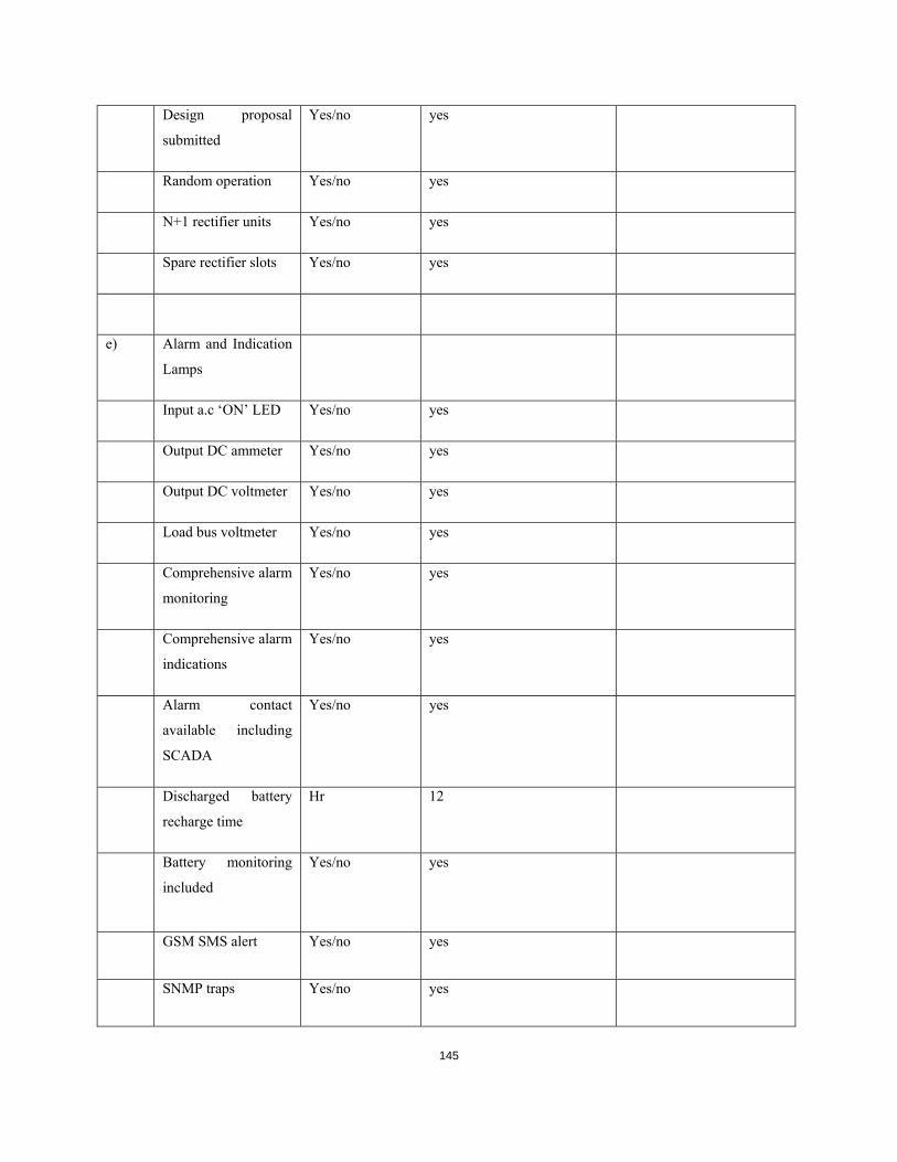
145
Design proposal
submitted
Yes/no yes
Random operation Yes/no yes
N+1 rectifier units Yes/no yes
Spare rectifier slots Yes/no yes
e) Alarm and Indication
Lamps
Input a.c ‘ON’ LED Yes/no yes
Output DC ammeter Yes/no yes
Output DC voltmeter Yes/no yes
Load bus voltmeter Yes/no yes
Comprehensive alarm
monitoring
Yes/no yes
Comprehensive alarm
indications
Yes/no yes
Alarm contact
available including
SCADA
Yes/no yes
Discharged battery
recharge time
Hr 12
Battery monitoring
included
Yes/no yes
GSM SMS alert Yes/no yes
SNMP traps Yes/no yes

146
MODBUS TCP/IP
capable
Yes/no yes
4 Blocking diodes
Manufacturer
Type/cat. No
Reference standard
Current rating
Peak inverse voltage
C Distribution Board
1 General
Manufacturer
Type of construction
Degree of protection
2 Busbars
Material copper

147
Minimum clearance
of busbar and
connections :
-Between phases
-Phase to earth
Maximum current
rating
amps
Dimensions mm
Short time current
rating
amps
3 Boost charge
contactors
Manufacturer
Maximum current
rating
amps
Coil ratings W
Method of
interlocking
Alarm relays
Manufacturer
Type and reference

148
Power consumption
Quiescent
Operated
W
E
5 Number and rating of
distribution
Circuits
6 Overall dimensions mm
7 Total weight kg
*NOTES:
Guaranteed Technical Particulars should be typed. Ticking in the Supplier’s offer box, or
simply stating “YES” or “COMPLIED” will not be accepted.
4.2.14.2 Recommended Spare Parts
The Tenderer shall enter in this schedule the recommended spares and its prices which he
recommends for 3 years operation with individual quantities and prices
Kenya Power may order all or any of the spares so recommended at his discretion.
The prices for spare parts shall not be included in the Tender Price.

149
Table 4-2List of 48V Battery Chargers
Station
Battery Ah- 12Hr
Charger output Rating (Amps)
Dual/Single battery system
Dual/Single Charger system
D.C.D.B
No.
LOT1
Nairobi
1 Airport 66/11
200 50 Single Single Single
2 Industrial 66/11
200 50 Single Single Single
3 Limuru 66/11
200 50 Single Single Single
4 Machako 66/11
200 50 Single Single Single
5 Mombasa Rd 66/11
200 50 Single Single Single
6 Muthurwa 66/11
200 50 Single Single Single
7 Nyaga 66/11
200 50 Single Single Single
8 Steel Billets 66/11
200 50 Single Single Single
9 Kikuyu 66/11
200 50 Single Single Single
10 EPZ 66/11
200 50 Single Single Single
Mt. Kenya
11 Karatina 33/11
200 50 Single Single Single
12 Kerugoya 33/11
200 50 Single Single Single
13 Embu 33/11
200 50 Single Single Single
14 Githambo 33/11
200 50 Single Single Single
15 Kiganjo 33/11
200 50 Single Single Single
16 Meru 33/11
200 50 Single Single Single
17 Othaya 33/11
200 50 Single Single Single
18 Nanyuki 33/11
200 50 Single Single Single
19 Ndarugu 33/11
200 50 Single Single Single
LOT2
Coast
1 Kanamai 33/11 kV
200 50 single Single Single
2 Mwambungo 33/11 kV
200 50 single Single Single
3 Watamu 33/11 kV
200 50 single Single Single
4 Msambweni 33/11kV
200 50 single Single Single
5 Utange 33/11 kV
200 50 single Single Single
6 Kaloleni 33/11
200 50 single Single Single
7 Mbaraki 33/11 kV
200 50 single Single Single
8 Mwatate 33/11 kV
200 50 single Single Single

150
LOT3
West Kenya
1 Cheptulu 33/11
200 50 single Single Single
2 Kitale 33/11
200 50 single Single Single
3 Eldoret Depo 33/11
200 50 single Single Single
4 Eldoret Industrial 33/11
200 50 Single Single Single
5 Kapsabet 33/11
200 50 single Single Single
6 Kericho 33/11
200 50 single Single Single
7 Kisii 33/11
200 50 single Single Single
8 Kisian 33/11
200 50 single Single Single
9 Kisumu East 33/11
200 50 single Single Single
10 Sotik 33/11
200 50 single Single Single
11 Mogogosiek 33/11
200 50 single Single Single
12 Homabay 33/11
200 50 single Single Single
13 Obote Rd 33/11
200 50 single Single Single
14 Sotik 33/11
200 50 single Single Single
Central Rift
15 Marura 33/11
200 50 Single Single Single
16 Nyahururu 33/11
200 50 Single Single Single
17 Kihoto 33/11
200 50 Single Single Single
17 Njoro 33/11
200 50 Single Single Single
18 Rongai 33/11
200 50 Single Single Single
19 Elburgon 33/11
200 50 Single Single Single
20 Mwariki 33/11
200 50 Single Single Single
21 Nakuru Depo 33/11
200 50 Single Single Single
22 Gilgil 33/11
200 50 Single Single Single
23 Soilo 132/33
200 50 Single Dual Dual