the influence of ferrule height and substance loss on the
TRANSCRIPT
Aus der Klinik für Zahnärztliche Prothetik, Propädeutik und Werkstoffkunde
(Direktor: Prof. Dr. M. Kern)
im Universitätsklinikum Schleswig-Holstein, Campus Kiel
an der Christian-Albrechts-Universität zu Kiel
The influence of ferrule height and substance loss on the fracture
resistance of endodontically treated premolars - An in-vitro study
[Der Einfluss der Höhe der Ferrule und Substanzverlust auf die Bruchfestigkeit
endodontisch behandelter Prämolaren: Eine In-vitro-Studie]
Inauguraldissertation
zur Erlangung der Würde eines Doktors der Zahnheilkunde
der Medizinischen Fakultät der Christian-Albrechts-Universität zu Kiel
vorgelegt von
ABDULAZIZ SAMRAN
aus Al-baidha, Jemen
Kiel 2014
II
1. Berichterstatter: Prof. Dr. Matthias Kern
2. Berichterstatter: Priv.-Doz. Dr. Katrin Hertrampf
Tag der mündlichen Prüfung: 12.12.2014
Zum Druck genehmigt, Kiel, den 15.12.2014
gez.:

CONTENTS
1. INTRODUCTION………………………………............ 1
1.1. REVIEW OF LITERATURE………………………………….. 2
1.2. RESTORATION OF ETT…………………..…..……………… 2
1.2.1. ANTERIOR TEETH……………………………………………. 3
1.2.2. PREMOLAR TEETH…………………………………………... 3
1.2.3. MOLAR TEETH…………………………....…………............... 3
1.3. FACTORS AFFECTING FRACTURE STRENGTH OF ETT 4
1.3.1. THE AMOUNT OF REMAINING WALLS………………………… 4
1.3.2. THE FERRULE EFFECT………………………………..…………... 4
1.3.3. CORE MATERIALS……………………………………..................... 5
1.3.4. POST DESIGN………………………….……………………………. 6
1.3.4.1. POST SHAPE…………….……...….……………………..……….. 6
1.3.4.2. POST LENGTH………………….……..……………..……………. 7
1.3.4.3. POST DIAMETER…………….……..……….……………………. 7
1.3.4.4. POST MATERIALS…….………..………..……………….............. 7
1.4. Bonding of posts……………………………………………...... 8
1.4.1. LUTING CEMENTS…………………….………..…………………… 9
1.5. Aim of the study…………….…….....…………... 10
2. MATERIALS AND METHODS…………………......... 11
2.1. TEST GROUPS…………………………………….…………. 11

II
2.2. CAST CROWN FABRICATION…………….………………. 17
2.3. FATIGUE LOADING DEVICE………………………............. 21
2.4. STATISTICAL ANALYSIS……………………………………. 23
3. RESULTS………………………..……………………… 23
4. DISCUSSION…………………………………………… 30
5. CONCLUSION…………………….……..…………….. 35
6. SUMMARY………………………………….………….. 36
7. ZUSAMMENFASSUNG………...…………………….. 38
8. REFERENCES……………….……………………........ 40
9. AKNOWLEDGMENT………..……………………….. 52
10. DEDICATION………………………………………….. 53
11. C.V…………………………….………………………… 54
12. APPENDIXES…………………………………….......... 56

ABBREVIATIONS
ANOVA analysis of variance
CEJ cemento-enamel junction
ETT endodontically treated teeth
FDPs fixed dental prostheses
FPs fiber posts
GFPs glass fiber posts
GPa gigapascal
N newton
RCT root canal treatment
RDPs removable dental prostheses
SD standard deviation

INTRODUCTION
1
1. INTRODUCTION
The restoration of the endodontically treated teeth (ETT) has been evaluated
and discussed widely in the dental literature. Despite the large number of in-
vitro and in-vivo investigations, however, there is still much confusion
regarding their ideal treatment.
ETT are a unique subset of teeth requiring restoration because of several
factors. Firstly, it was thought that the dentin of ETT differed significantly from
vital dentin [45]. However, more current research casts doubt on this
assumption [49]. Secondly, a percentage of structural integrity is lost because of
the endodontic access preparation [63, 84]. This loss clearly has a negative
effect on the fracture resistance of ETT. Thirdly, the neurosensory feedback
mechanism is impaired with the removal of the pulpal tissue, which may result
in decreased sensory protection of ETT during mastication [83]. The most
important factor which is affecting the prognosis of ETT is the amount of
remaining coronal tooth structure and ferrule height before the final restoration
[63, 117]. This factor is much more important than others that are reported, such
as post material, post design (diameter and length), cement type and core
materials [54, 114].

INTRODUCTION
2
1.1. REVIEW OF LITERATURE
ETT should have a good prognosis to resume full function and serve
satisfactorily as abutment teeth for crowns, fixed dental prostheses (FDPs) or
removable dental prostheses (RDPs). Several studies have suggested that the
dentin in non-vital ETT is different from dentin in vital teeth [24, 45, 85]. It was
thought that the dentin in ETT is more brittle because of water loss and loss of
collagen. However, other studies contradicted this view. Sedgley and Messer
[95] studied the biomechanical properties such as punch shear strength,
toughness, hardness, and load to fracture of ETT (mean time since endodontic
treatment: 10.1 yr.) and compared them to their contralateral vital pairs. Their
findings did not support the conclusion that ETT are more brittle. Cheron et al.
[26] studied the nanomechanical changes of the ETT and compared them with
vital teeth. They found that root canal treatment does not result in
nanomechanical changes to radicular intertubular dentin. Huang et al. [49]
compared the physical and mechanical properties of dentin specimens from
teeth with and without endodontic treatment at different levels of hydration.
They concluded that neither dehydration nor endodontic treatment caused
degradation of the physical or mechanical properties of dentin.
1.2. Restoration of ETT
The restoration of ETT is one of the most challenging situations of the
dentist's clinical practice and has long been a concern of dentistry, because it
involves procedures related to several areas, such as Endodontics, Operative
Dentistry, and Prosthetics. Restoration of ETT has been evaluated and discussed
widely in the dental literature and there are a variety of materials and techniques
advocated for restoring pulpless teeth. Restorative treatment may vary, ranging
from a relatively small direct restoration to more complex indirect restorations
involving the placement of an intraradicular post and core and the indirect

INTRODUCTION
3
restoration itself. Primarily, preservation of tooth tissue, presence of a ferrule
effect, and adhesion are regarded as the most effective conditions for long-term
success of the restorative procedure [33, 34, 36, 94, 107]. The treatment of the
ETT should include the decision of whether or not root posts should be used.
The use of posts, however, does not increase the fracture resistance
significantly. This has been shown in several comparative in-vitro studies [18,
44, 66], but the use of posts serves to improve retention of the core. The
decision regarding post placement should be made based on the position of the
tooth in the arch [81, 99], the amount of coronal remaining tooth structure [63],
and the functional requirements of the tooth [42], e.g. if a tooth would be used
as an abutment for removable or fixed dental prostheses.
1.2.1. Anterior teeth
Anterior teeth are subjected to shearing forces and are usually restored
with posts [1]. When there is no functional or aesthetic requirement for a full-
coverage restoration, a post is not indicated. If a full-coverage restoration is
chosen, however, the decision to place a post is dictated by the amount of
coronal remaining tooth structure after the crown preparation is completed and
the functional requirements of the restored tooth [44, 99].
1.2.2. Premolar teeth
Premolars are subjected to vertical forces and shear forces if there is
unilateral group guidance. A decision regarding post placement is made based
mainly on the remaining coronal tooth structure [63], and the functional
requirements of the tooth [94]. There might be also considerable shear forces in
premolars if there is unilateral group guidance.
1.2.3. Molar teeth
Posterior molar teeth are subjected to vertical forces and posts are rarely
required when there is no large percentage of coronal tooth structure missing

INTRODUCTION
4
[12, 92]. When a decision regarding post placement is taken because of lack of
adequate remaining coronal tooth structure, it should be placed usually in the
largest root canal [94], i.e. the palatal canal in the maxillary molar and the distal
canal in the mandibular molar.
1.3. Factors affecting the fracture strength of ETT
1.3.1. The amount of remaining walls
The amount of remaining tooth structure is probably the most important
predictor of clinical success and to raise the fracture strength of ETT [7]. In
terms of failure loads the height of the residual dentin was reported to be more
important than the post system used. Other in-vivo and in-vitro studies [2, 19,
29, 106] have shown the importance of height and location of the remaining
tooth structure for the mechanical properties of restored ETT. Mangold and
Kern [63] reported an improved resistance to fracture when more residual
dentin walls are available. They stated that the presence of at least 2 residual
dentin walls is important to avoid using intraradicular posts but they did not
indicate the effect of varying ferrule height in their study.
1.3.2. The ferrule effect
The ferrule (Fig. 1) is an encircling band of the crown around the coronal
surface of the tooth [98], more precisely, parallel walls of dentin extending
coronally from the crown margin provide a ‘‘ferrule,’’ which after being
encircled by a crown provides a protective effect by reducing stresses within a
tooth called the ‘‘ferrule effect’’ [102]. An adequate ferrule is necessary for a
successful post-retained restoration. Several studies reported an improved
resistance to fracture of ETT when an encircling ferrule was used with a post
[19, 31, 46, 118]. The ferrule can reduce significantly the incidence of fractures
in non-vital teeth by reinforcing the tooth at its external surface and
redistributing applied forces which concentrate at the narrowest point around

INTRODUCTION
5
the circumference of the tooth [100]. In addition, it helps to maintain the
integrity of the cement seal of the crown [60].
Fig. 1 The ferrule effect.
1.3.3. Core materials
The presence of significant coronal tooth structure loss requires abutment
build-up around a post [89]. Several core materials are available such as:
amalgam, composite resins, glass ionomer cements, alloys and ceramics. The
elastic moduli of some commonly used core materials are as follows: 17-21 GPa
(composite resin), 28-59 GPa (amalgam), 218-224 GPa (cobalt-chromium
alloy), and 90-95 GPa (Type IV gold alloy) [28]. Depending on the post
material being used and its physical properties, the post and core can absorb
occlusal and functional stresses that are applied to the bonded post/crown
complex and redirect them along the long axis of the remaining root which lead
to increase fracture strength of ETT [27, 91]. The stiffer core materials increase
the cervical stress and diminish the apical stress [116]. Several laboratory and
clinical studies supported the use of composite materials for building up the

INTRODUCTION
6
core portion [47, 82, 108]. Restorations with fiber posts (FPs) and composite
resin cores were found to be more effective than amalgam in preventing fracture
of ETT [64]. With the evolution of the dentin bonding technology [57], it may
be possible to obtain an integrated tooth-post-core bonded restoration, instead of
an assemblage of heterogeneous materials (i.e., post [metal], cement [zinc
phosphate], and core [metal, amalgam, or composite resin]).
1.3.4. Post design
In the past a post was generally placed in an attempt to strengthen the tooth.
However, as dentin has to be sacrificed, especially when a metal post is utilized,
a post does not strengthen the root, but serves solely to improve retention of the
core. The purpose of a post and core together is to reinforce the remaining
coronal tooth structure and to replace missing coronal tooth structure [86].
Although some studies indicated that a post strengthens a tooth [56, 111], but
most studies suggested that this is not the case [18, 44, 66, 87]. In a study where
the reinforcement effect of cast posts and pins was examined, it was found that
the ETT without posts which served as control group were twice as resistant to
fracture as the teeth treated with posts or pin-retained cores [61].
1.3.4.1. Post shape
Many commercially available prefabricated posts exist. For example, the
axial form is either tapered or parallel, and the surface can be smooth, serrated
with or without vents, or threaded using taps or self-threading. Parallel-sided
posts are more retentive than tapered posts [110], and they distribute stress more
uniformly along their length during function which may lead to lower fracture
rates of ETT than do tapered posts [97]. Threaded posts are more retentive but
can predispose the root to fracture in ETT [40]. Screws have a higher incidence
of root fractures in ETT and their survival rate may be significantly reduced
[30].

INTRODUCTION
7
1.3.4.2. Post length
There are many guidelines in the literature concerning the length of the post.
Some studies have suggested that the post length should be equal to a certain
amount of the root, e.g. half the length of the root [17, 52], two thirds of the root
length [58] or at least half way between the apex of the root and the alveolar
crest of supporting bone [79, 104]. The length of the post affects stress
distribution in the root of ETT which affects its resistance to fracture [50]. In-
vitro biomechanical studies also have suggested that better stress distribution
occurred with longer posts [48]. An increased post length was associated with
an improved fracture strength of ETT [111]. Generally, it has been shown that
the post length is less important for fracture resistance of ETT than the ferrule
effect [50].
1.3.4.3. Post diameter
One of the controversial factors in fracture resistance of dental roots is the
diameter of the endodontic posts. A post requires an adequate diameter to
achieve favorable physical and mechanical characteristics without the risk of
fracture [11]. However, increasing the diameter of the post adds to its strength
but at expenses of the sound tooth structure, thus leading to weakening of the
whole entity of ETT [73]. The post space should be prepared conservatively and
at least 1.0 mm thickness of sound dentinal wall should remain around the post
[11]. On the other hand, an increase in the post’s width will increase the risk of
root fracture [43, 101]. Robbin [86] recommended that the diameter should be
''as small as possible'' to increase the fracture resistance of ETT by minimizing
the loss of the tooth structure.
1.3.4.4. Post materials
Posts can be divided into two large groups: custom-made and pre-
fabricated posts. The custom-made cast posts have been used for many years

INTRODUCTION
8
with good success [22, 30]. They exhibit some features unfavorable to tooth
remnant preservation, such as irregular stress dissipation and stress
concentration at apical area which may lead to root fracture of ETT [51]. On the
other hand, prefabricated non-metal posts save time and can provide satisfactory
results [105, 109]. They provide retention to a core portion [98] which is
directly built up onto the post with a composite resin. Accordingly, it might be
assumed that FPs offer additional advantages such as that their modulus of
elasticity is similar to dentin (Fig. 2) which allows reducing stress transmission
to root canal walls and increasing the fracture strength of ETT [8]. It has been
also suggested that the failure with FPs is less likely to include irreparable
root fracture of ETT than with metal posts [3, 27].
Fig. 2: Elasticity modulus (GPa) of dentin and post materials (3M ESPE
internal data).
1.4. Bonding of posts
Bonding of posts to radicular dentin is one of the most challenging situations
faced by the clinician. Several cements, such as zinc phosphate, glass ionomer,
modified glass-ionomer and resin cements, can be used to cement posts systems
to dentin walls [14, 37, 53, 101, 113]. Zinc phosphate cement has been widely
used in FDPs due to its easy handling properties and satisfactory long-term
clinical results [53]. It bonds by mechanical interlocking to the dentin and the
prosthetic materials [6]. Glass-ionomer cements have also been used in luting

INTRODUCTION
9
posts. Their advantages are ease of use, good bonding to tooth structure,
releasing significant amounts of fluoride, and anticariogenic properties [28].
Several studies have reported higher resistance to fatigue for resin cements
compared to brittle zinc phosphate cements and glass ionomer cement [4, 10,
55, 65, 68]. Resin cements are especially recommended when luting FPs and
ceramic posts [65]. Posts form a bonded unit between root and coronal dentin,
adhesive systems, resin cements, and composite build-up (Monoblock) which
lead to raising the fracture strength of ETT [115].
In clinical studies, it has been shown that failure of adhesively luted FPs
often occurs due to debonding of the post [37, 71].
1.4.1. Luting cements
Since the 1980s, resin cements have been preferred to conventional zinc-
phosphate cements for post luting, because they have been shown to increase
the retention of the post [88] and the overall resistance against fracture of ETT
[76]. Due to the low elastic modulus of the adhesive cement, it may act as a
shock absorber, thus decreasing the risk of fracture of ETT [68]. Moreover, the
elastic modulus of composite cements is in the same range of both FPs and
dentine. The resultant homogeneous biomechanical unit allows a more uniform
stress distribution, which better preserves the weakened tooth structure in ETT
[77].

INTRODUCTION
10
1.5. AIM OF THE STUDY
The review of the literature showed that the increase in either ferrule
height or the number of remaining walls of weakened ETT may increase the
teeth resistance to fracture. However, little is known about the combined effect
of both factors, i.e. remaining walls and ferrule height, in terms of
reinforcement of weakened ETT. Therefore, the aim of this study was to
evaluate the fracture resistance of endodontically treated premolars restored
with glass-fiber posts when different ferrule heights and varying degrees of
substance loss were incorporated.
The null hypothesis of the study is that neither the ferrule height nor the
amount of residual coronal dentin would affect the fracture resistance of
crowned premolars.

MATERIALS AND METHODS
11
2. MATERIALS AND METHODS
2.1. Test groups
Materials used in the restorative procedures are listed in Table 1. After
informed consent was obtained according to the regulations of the ethical
committee of the Christian-Albrechts University at Kiel, eighty recently
extracted caries-free lower first premolars were selected, which removed for
periodontal or orthodontics reasons, and stored in 0.1% thymol solution (Caelo,
Hilden, Germany). The teeth were cleaned with a hand scaler and stored at
room temperature during the study. Endodontic access cavities were prepared
using a water cooled air turbine handpiece. The teeth were endodontically
prepared using the step-back technique to an ISO size 50 (K-files; Dentsply De
Trey, Constance, Germany), irrigated with 3% sodium hypochlorite solution
(Hedinger, Stuttgart, Germany) and dried with paper points (Coltene/Whaledent
Inc, Langenau, Germany).
Table 1- Materials used for restorative procedures
Material Company Batch number
ER Dentin Post Brasseler, Lemgo, Germany 676303
Clearfil Core Kuraray, Osaka, Japan 041523
Permadyne Penta H 3M/Espe, Seefeld, Germany H 434544, L 422524
Panavia 21 Kuraray, Osaka, Japan 041344
Ketac Cem Maxicap 3M/Espe , Seefeld, Germany 347837
Cobalt-chromium alloy Wirobond C, Bego, Bremen, Germany 3533
During root canal preparation, the working length was set at 1 mm short of
the apical foramen. Each canal was obturated using the lateral condensation
method with gutta-percha points (Coltene/Whaledent Inc, Langenau, Germany)

MATERIALS AND METHODS
12
and sealed with an eugenol-free epoxyamine resin sealer (AH Plus; Dentsply De
Trey, Constance, Germany) [21, 70]. The coronal aspect of the gutta-percha was
removed with a heated probe and the endodontic access cavities were filled with
a temporary filling material. The teeth roots were embedded into brass tubes,
using an auto-polymerizing resin (Technovit 4000; Heraeus Kulzer, Wehrheim,
Germany) up to 2 mm apical to the cemento-enamel junction (CEJ) and oriented
their long axes perpendicular to the horizontal using a custom-made surveyor
(Fig. 3). The ETT received 0.8 mm shoulder finish lines which were mesial and
distal 1 mm more coronal than the facial and lingual surfaces and which were
cervical 1 mm to the cemento-enamel junction (CEJ). Burs were replaced after
8 preparations, in order to ensure high cutting efficacy. For teeth preparations,
diamond rotary cutting instruments under copious air-water cooling (Komet
Dental, Lemgo, Germany) were used in a high-speed handpiece mounted on a
custom-made parallelometer to standardize the preparation for all specimens.
Fig. 3: Tooth preparation using a custom-made surveyor.
The teeth were assigned randomly to 5 groups of 16 teeth each according
to the ferrule height (Figs. 4&5). The properties of the specimens included in
each group were as follows: group A (control group): Specimens without
circumferential ferrule; group B: Circumferential ferrule 0.5 mm above the

MATERIALS AND METHODS
13
finish line; group C: Circumferential ferrule 1 mm above the finish line; group
D: Circumferential ferrule 1.5 mm above the finish line; and group E:
Circumferential ferrule 2 mm above the finish line.
Eight specimens per subgroup were chosen because in the masticatory
simulator 8 specimens can be loaded at a time.
Fig. 4: Prepared specimens with two dentinal wall and different ferrule
height: a) sound specimen (without any preparation), b) with 2 mm ferrule
height, c) with 1.5 mm ferrule height, d) with 1 mm ferrule height, e) with 0.5
mm ferrule height, f) without ferrule.

MATERIALS AND METHODS
14
Fig. 5: Flow chart of study design.
For all teeth, post spaces were accomplished with a tapered drill (ER-post
kit; Brasseler, Lemgo, Germany) of ISO size 90 (Fig. 6) to achieve an
intraradicular post length of 7.5 mm. The coronal opening of the post space
were enlarged in a facio-lingual direction to a width of 3 mm and depth of 2 mm
to resist rotation and to standardize the coronal openings and the thickness of
residual coronal walls. The walls of the post preparation were roughened using
a diamond-coated hand instrument 3 times (ER Post Systems; Brasseler,
Lemgo, Germany) [16].

MATERIALS AND METHODS
15
Fig. 6: ER-Post-System with ER-Dentin-Post (Komet, Brasseler, Lemgo,
Germany).
The GFPs (Fig. 7) (Komet ER DentinPost; ISO size 90, Brasseler,
Lemgo, Germany) were airborne-particle abraded for 5 seconds at a distance of
30 mm with 50 μm alumina particles (Heraeus Kulzer, Wehrheim, Germany) at
0.25 MPa and cleaned ultrasonically in 96% isopropanol (German Federal
Monopoly Administration for Spirits, Hamburg, Germany) for 3 minutes [15].
Fig. 7: The GFP inside the root canal.
The post spaces were then irrigated with a 3% sodium hypochlorite
solution and dried with paper points, followed by irrigation with 70% ethanol
(German Federal Monopoly Administration for Spirits, Hamburg, Germany)
and drying with paper points. The irrigation with 70% ethanol, simulating the
clinical situation, was used to disinfect and dry the canals. The posts were luted
with adhesive composite-resin cement (Panavia 21; Kuraray Medical, Osaka,

MATERIALS AND METHODS
16
Japan) after conditioning the dentin with the system’s autopolymerizing primer
(ED-Primer; Kuraray, Osaka, Japan) for 60 seconds. The resin cements were
mixed and applied according to the manufacturer's instructions (Fig. 8), equal
amounts of the catalyst and the universal pastes were dispensed by turning the
syringe of each paste one complete turn. The dispensed pastes were then mixed
for 20-30 seconds using a plastic spatula. Excess luting resin was used to coat
the coronal portion of the post.
Fig. 8: Panavia 21 resin cement.
An auto-polymerizing composite resin (Clearfil Core; Kuraray Medical,
Osaka, Japan) was applied as the core material. After complete polymerization
of the resin, the core was prepared to the required dimensions (Fig. 9).
Fig. 9: Dimensions of preparation, restoration and ferrule height (in mm).

MATERIALS AND METHODS
17
2.2. Cast crown fabrication
Impressions (Fig. 10) of the prepared specimens were made with a
polyether impression material (Permadyne Penta H; 3M/Espe, Seefeld,
Germany). After 30 minutes, the impressions were poured in type IV stone (Fig.
11) (GC Fujirock EP, Leuven, Belgium).
Fig. 10: Impression making for the prepared specimen.
Fig. 11: Final impression and die stone.
To obtain identical crown dimensions in all specimens, a stylized
reference crown (Fig. 12) with a 30-degree angulation of the buccal cusp to the

MATERIALS AND METHODS
18
vertical tooth axis was created in wax (Crowax; Renfert GmbH, Hilzingen,
Germany).
Fig. 12: Controlling of the inclination of the buccal cusp slope with
parallelometer.
Then, the crowns were duplicated onto the other dies by inserting heated
liquid wax into a silicone mold (Deguform, Degudent, Hanau-Wolfgang,
Germany). The crown wax patterns were measured using a wax gauge to assure
that all the patterns have the same dimensions. The crown wax patterns were
invested and cast (Fig. 13) in cobalt-chromium alloy (Wirobond C; Bego,
Bremen, Germany) following the instructions of the manufacturer. The internal
surfaces of the crowns were airborne-particle abraded with 50 μm alumina
(Aluminum Oxide Abrasive; Heraeus Kulzer GmbH, Germany) at 0.25 MPa
pressure and then ultrasonically cleaned in 96% isopropanol (German Federal
Monopoly Administration for Spirits).
Fig. 13: Cast crowns.

MATERIALS AND METHODS
19
The tooth preparations were cleaned with a rotary brush (Omnident;
Rodgau, Germany) and pumice (Sterilbimspaste; Ernst Hinrichs GmbH, Goslar,
Germany). Then, the crowns were cemented using glass-ionomer cement (Ketac
Cem Maxicap; 3M/ESpe, Seefeld, Germany) which was mixed according to the
manufacturer’s instructions. During the cementing procedures, each crown was
held in place for 7 minutes under a 5-kg load using custom made device (Figs.
14 & 15).
Fig. 14: Crown cementation.
Fig. 15: Specimens after cementation.
After storing the specimens in deionized water at 37 °C, all specimens
underwent combined masticatory loading simulation in a dual-axis masticatory
MATERIALS AND METHODS
20
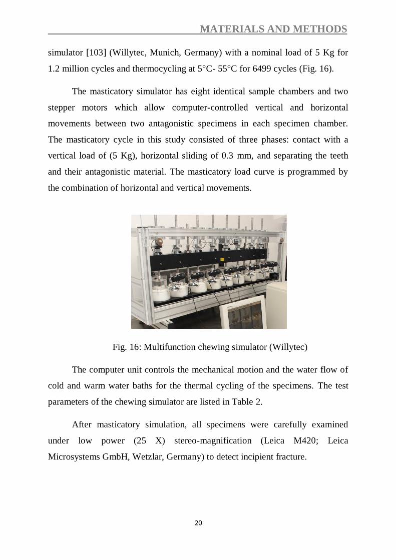
simulator [103] (Willytec, Munich, Germany) with a nominal load of 5 Kg for
1.2 million cycles and thermocycling at 5°C- 55°C for 6499 cycles (Fig. 16).
The masticatory simulator has eight identical sample chambers and two
stepper motors which allow computer-controlled vertical and horizontal
movements between two antagonistic specimens in each specimen chamber.
The masticatory cycle in this study consisted of three phases: contact with a
vertical load of (5 Kg), horizontal sliding of 0.3 mm, and separating the teeth
and their antagonistic material. The masticatory load curve is programmed by
the combination of horizontal and vertical movements.
Fig. 16: Multifunction chewing simulator (Willytec)
The computer unit controls the mechanical motion and the water flow of
cold and warm water baths for the thermal cycling of the specimens. The test
parameters of the chewing simulator are listed in Table 2.
After masticatory simulation, all specimens were carefully examined
under low power (25 X) stereo-magnification (Leica M420; Leica
Microsystems GmbH, Wetzlar, Germany) to detect incipient fracture.

MATERIALS AND METHODS
21
Table 2. Test parameters
Cold/hot bath temperature 5°C/55°C
Vertical movement 6 mm
Rising speed 55 mm/s
Descending speed 30 mm/s
Weight per specimen 5 kg
Kinetic energy 2,250 x 10-6 J
Dwell time 30 s
Horizontal movement 0.3 mm
Forward speed 30 mm/s
Backward speed 55 mm/s
Cycle frequency 1.3 Hz
2.3. Fatigue loading device
All specimens which survived the dynamic loading were quasi-statically
loaded with a crosshead speed of 1 mm/min at an angle of 30 degrees to the
longitudinal axis of the tooth in a universal testing machine (Zwick
Z010/TN2A; Zwick, Ulm, Germany) until they were fractured (Fig. 17).
Loading was on the lingual incline of the buccal cusp at a distance of 2 mm
from the central fossa of the crown (Fig. 18). Specimens were visually
examined for the type and location of failure, as well as the direction of failure.

MATERIALS AND METHODS
22
Fig. 17: Universal testing machine Z010/TN2A
Fig. 18: Schematic representation of the fracture load tests in the universal
testing machine

MATERIALS AND METHODS
23
2.4. Statistical analysis
Data were explored for normality using Kolmogorov-Smirnov and Shapiro-
Wilk tests, which showed that data were normally distributed. Levene test for
homogeneity of variance indicated homogeneity of variances between groups.
Two-way analysis of variance (ANOVA) was used to compare fracture
resistance means among the five groups followed by multiple comparisons
using Tukey HSD test (α=.05). The confidence level was 95%. Statistical
analysis was performed with SPSS 18.0 (SPSS 18.0 for Windows; SPSS, Inc,
Chicago, IL, USA).
According to the significance level (α=.05) and the sample size (n = 8), the test
of choice had adequate power to detect statistical differences which could be
used to provide clinical recommendations (F = 0.11). Failure modes were
recorded and statistically analyzed with Chi-square (X²) testing for significant
correlation between design and failure modes.
RESULTS
24
3. RESULTS
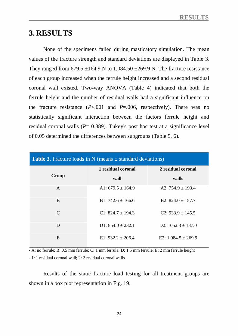
None of the specimens failed during masticatory simulation. The mean
values of the fracture strength and standard deviations are displayed in Table 3.
They ranged from 679.5 ±164.9 N to 1,084.50 ±269.9 N. The fracture resistance
of each group increased when the ferrule height increased and a second residual
coronal wall existed. Two-way ANOVA (Table 4) indicated that both the
ferrule height and the number of residual walls had a significant influence on
the fracture resistance (P≤.001 and P=.006, respectively). There was no
statistically significant interaction between the factors ferrule height and
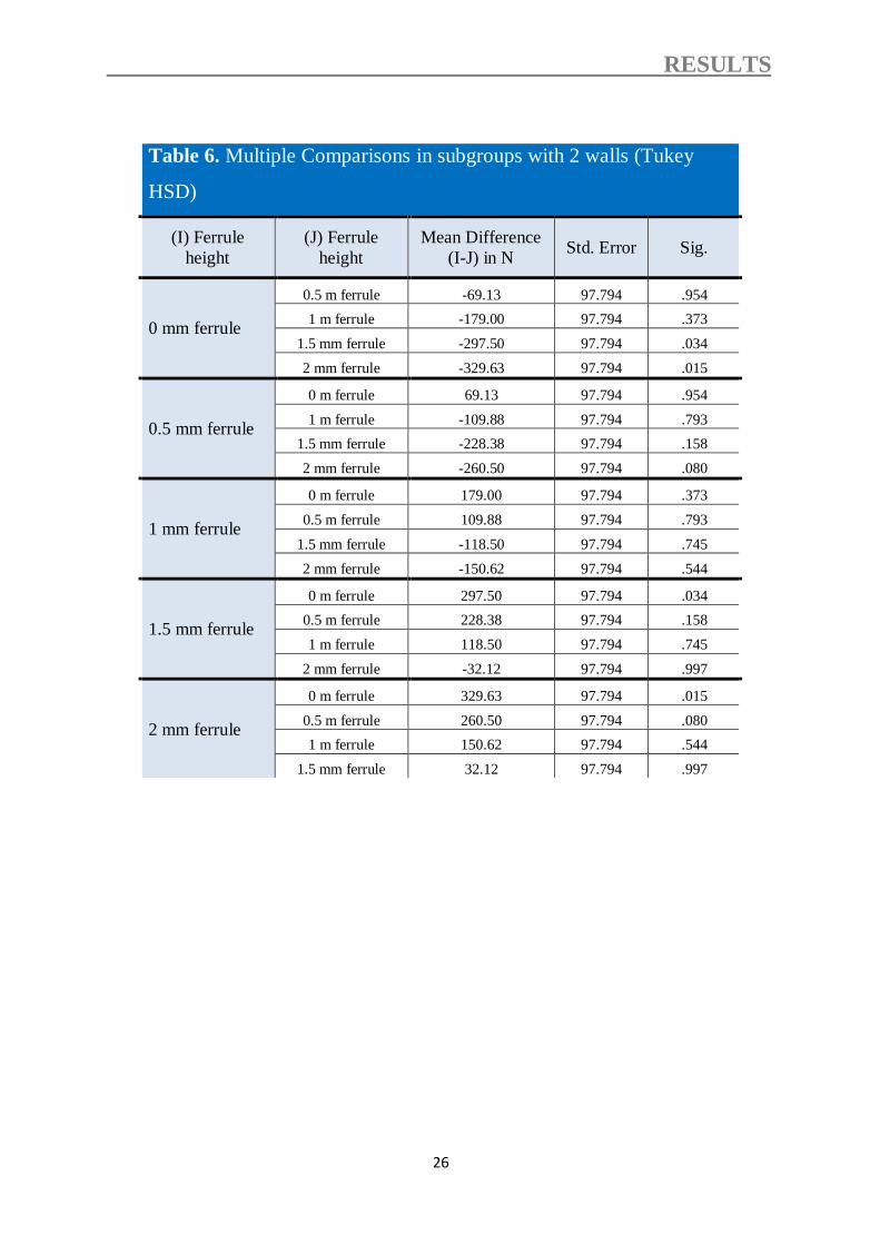
residual coronal walls (P= 0.889). Tukey's post hoc test at a significance level
of 0.05 determined the differences between subgroups (Table 5, 6).
Table 3. Fracture loads in N (means ± standard deviations)
Group
1 residual coronal
wall
2 residual coronal
walls
A A1: 679.5 ± 164.9 A2: 754.9 ± 193.4
B B1: 742.6 ± 166.6 B2: 824.0 ± 157.7
C C1: 824.7 ± 194.3 C2: 933.9 ± 145.5
D D1: 854.0 ± 232.1 D2: 1052.3 ± 187.0
E E1: 932.2 ± 206.4 E2: 1,084.5 ± 269.9
- A: no ferrule; B: 0.5 mm ferrule; C: 1 mm ferrule; D: 1.5 mm ferrule; E: 2 mm ferrule height
- 1: 1 residual coronal wall; 2: 2 residual coronal walls.
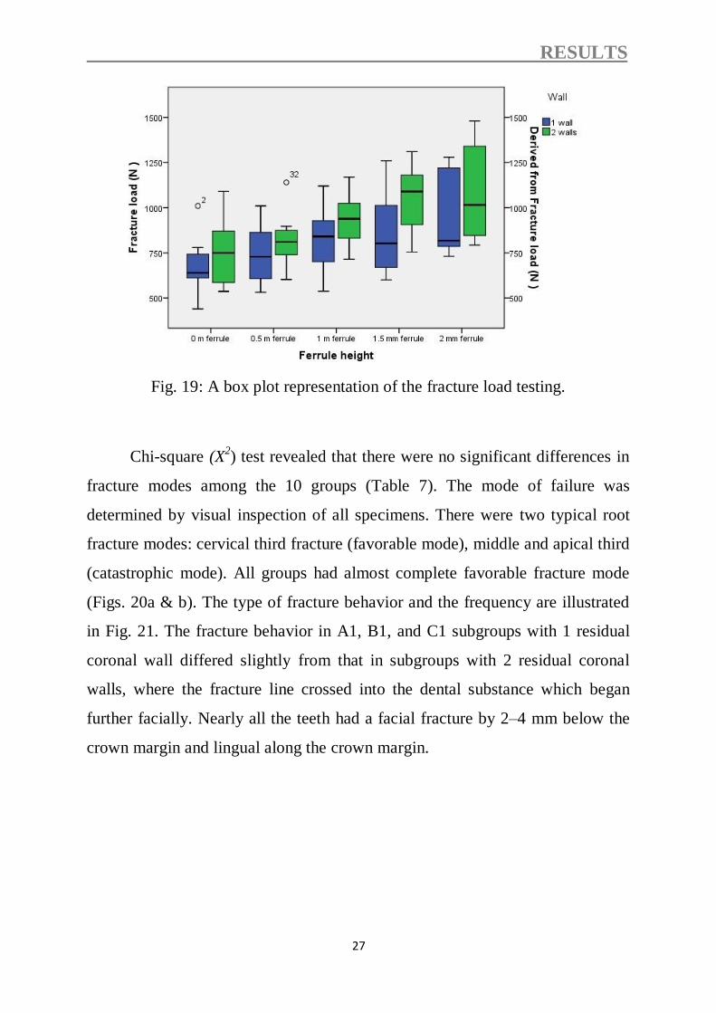
Results of the static fracture load testing for all treatment groups are
shown in a box plot representation in Fig. 19.

RESULTS
25
Table 4. Summary of 2-way ANOVA of main factors
Source of
variation
Sum of
Squares df
X Mean Square F p
Ferrule 912096.5 4 228024.1 6 <.001
Wall 304057.8 1 304057.8 8 .006
Ferrule X Wall 42919.2 4 10729.8 .3 .889
Error 2663122.5 70 38044.6
Total 6.4 80
X Degrees of freedom.
Table 5. Multiple comparisons in subgroups with 1 wall (Tukey
HSD)
(I) Ferrule
height
(J) Ferrule
height
Mean Difference
(I-J) in N Std. Error Sig.
0 mm ferrule
0.5 m ferrule -63.13 97.255 .966
1 m ferrule -145.25 97.255 .573
1.5 mm ferrule -174.50 97.255 .393
2 mm ferrule -252.75 97.255 .092
0.5 mm ferrule
0 m ferrule 63.13 97.255 .966
1 m ferrule -82.13 97.255 .915
1.5 mm ferrule -111.38 97.255 .782
2 mm ferrule -189.63 97.255 .311
1 mm ferrule
0 m ferrule 145.25 97.255 .573
0.5 m ferrule 82.13 97.255 .915
1.5 mm ferrule -29.25 97.255 .998
2 mm ferrule -107.50 97.255 .803
1.5 mm ferrule
0 m ferrule 174.50 97.255 .393
0.5 m ferrule 111.38 97.255 .782
1 m ferrule 29.25 97.255 .998
2 mm ferrule -78.25 97.255 .927
2 mm ferrule
0 m ferrule 252.75 97.255 .092
0.5 m ferrule 189.63 97.255 .311
1 m ferrule 107.50 97.255 .803
1.5 mm ferrule 78.25 97.255 .927
RESULTS
26
Table 6. Multiple Comparisons in subgroups with 2 walls (Tukey
HSD)
(I) Ferrule
height
(J) Ferrule
height
Mean Difference
(I-J) in N Std. Error Sig.
0 mm ferrule
0.5 m ferrule -69.13 97.794 .954
1 m ferrule -179.00 97.794 .373
1.5 mm ferrule -297.50 97.794 .034
2 mm ferrule -329.63 97.794 .015
0.5 mm ferrule
0 m ferrule 69.13 97.794 .954
1 m ferrule -109.88 97.794 .793
1.5 mm ferrule -228.38 97.794 .158
2 mm ferrule -260.50 97.794 .080
1 mm ferrule
0 m ferrule 179.00 97.794 .373
0.5 m ferrule 109.88 97.794 .793
1.5 mm ferrule -118.50 97.794 .745
2 mm ferrule -150.62 97.794 .544
1.5 mm ferrule
0 m ferrule 297.50 97.794 .034
0.5 m ferrule 228.38 97.794 .158
1 m ferrule 118.50 97.794 .745
2 mm ferrule -32.12 97.794 .997
2 mm ferrule
0 m ferrule 329.63 97.794 .015
0.5 m ferrule 260.50 97.794 .080
1 m ferrule 150.62 97.794 .544
1.5 mm ferrule 32.12 97.794 .997
RESULTS
27
Fig. 19: A box plot representation of the fracture load testing.
Chi-square (X2) test revealed that there were no significant differences in
fracture modes among the 10 groups (Table 7). The mode of failure was
determined by visual inspection of all specimens. There were two typical root
fracture modes: cervical third fracture (favorable mode), middle and apical third
(catastrophic mode). All groups had almost complete favorable fracture mode
(Figs. 20a & b). The type of fracture behavior and the frequency are illustrated
in Fig. 21. The fracture behavior in A1, B1, and C1 subgroups with 1 residual
coronal wall differed slightly from that in subgroups with 2 residual coronal
walls, where the fracture line crossed into the dental substance which began
further facially. Nearly all the teeth had a facial fracture by 2–4 mm below the
crown margin and lingual along the crown margin.

RESULTS
28
Table 7. Fracture mode of each group
Groups
Failure mode
E2 E1 D2 D1 C2 C1 B2 B1 A2 A1
8 8 7 7 7 7 8 7 8 8
favorable
(100%) (100%) (87.5%) (87.5%) (87.5%) (87.5%) (100%) (87.5%) (100%) (100%)
0 0 1 1 1 1 0 1 0 0
Non-favorable
(0%) (0%) (12.5%) (12.5%) (12.5%) (12.5%) (0%) (12.5%) (0%) (0%)
Group: X2= 4.324; DF = 9; P = 0.661.
Fracture mode: X2= 6.452; DF = 9; P = 0.632.

RESULTS
29
Fig. 20 a: Fracture mode of a specimen with one dentinal wall (buccal wall).
Fig. 20b: Fracture mode of a specimen with two dentinal walls (buccal &
lingual wall).
Fig. 21: Schematic representation of the fracture modes and their frequency.
DISCUSSION
30
4. DISCUSSION
The present study investigated the influence of five ferrule heights on the
fracture resistance of crowned lower premolars. Teeth in subgroups were either
with 1 or 2 residual coronal dentin walls. Eight specimens per group were
exposed to thermal cycling and mechanical loading and loaded until fracture.
Eight specimens per subgroup were chosen because 8 specimens can be loaded
at a time in the masticatory simulator. A thymol solution is an antifungal agent
[5]. For this reason 0.1 % thymol was used since the teeth had to be stored for
an extended period as collection proceeded. Teeth were generally prepared;
however, with their finish lines following the coronal extension of the gingival
tissue level interproximally. To mimic this clinical condition, the finish lines in
this study were mesial and distal 1 mm more coronal than the facial and lingual
surfaces and which were cervical to the CEJ. Different materials have been used
to simulate the periodontal ligament [35, 69, 96]. However, the benefits of using
such materials are questionable since the elasticity is different from that of the
periodontal membrane and the elastic nature of the alveolar bone is not taken
into account. Moreover, using an artificial periodontal ligament might be
important when testing splinted restorations on multiple teeth to achieve
differential abutment tooth mobility but the benefit of using an artificial
periodontal ligament when testing single tooth is not so clear. An artificial
membrane would have absorbed some stress during dynamic loading; however
as in our study the restored teeth did not fail during dynamic loading our
somewhat "harder" test conditions did not affect the survival of teeth. Teeth in
this study were directly mounted into auto-polymerizing resin and the force was
absorbed by the tooth tissue primarily, which may have resulted in a lower
failure load than would be seen in vivo.
A custom-made parallelometer was used to standardize the preparation
for all specimens and the required dimensions were obtained prior to core

DISCUSSION
31
fabrication by reducing the tooth structure in a stepwise manner using a digital
sliding caliper to control dimensions. After core fabrication only a low speed
handpiece with a fine grain diamond was used to finish the preparation and only
a minimal additional amount of dentin was removed by that procedure. It must
be admitted that this resulted in a slight overestimation of the remaining coronal
tooth structure. However, as this was done in the same manner in each group it
is assumed that this did not affect the results considerably.
A post length of 10.5 mm was prepared to ensure an adequate post length [5, 41,
46]. Conventional cements are non-adhesive and rely primarily on mechanical
interlocking to retain the dowel core. These inorganic cements have a relative
high rigidity and low elasticity. The advantages of using a resin cementation
system as in this study are supported by results of the studies conducted by
Mendoza and Eakle [67] and Mendoza et al. [68].
Composite resin core material was used in this study since it has a higher
fracture resistance than the other core materials such as amalgam and glass
ionomer cement [25, 64, 108] because a stronger union between core and tooth
structure was established using the adhesive bonding agents. Humans perform
an average of 250,000 chewing cycles per year [32, 90]. In this study, 1,200,000
load cycles were performed [32], estimated to equate to 5 years of normal
function. Force applied at 150° from the long axis of the mandibular premolar
was employed to simulate functional working-side buccal cusp loading.
The first hypothesis that the ferrule height would not affect the fracture
resistance of crowned premolars was rejected. The ferrule height had a
significant influence on the final fracture resistance (P≤.001), which was
reduced to approximately 37% when teeth with 2 mm ferrule height were
compared with teeth without ferrule. In addition, the amount of residual coronal
dentin had a significant influence on the final fracture resistance of the restored

DISCUSSION
32
teeth (P=.006). Therefore, the second hypothesis that the amount of residual
coronal dentin would not affect the fracture resistance of crowned premolars
was also rejected.
Unfortunately, the authors identified no other studies that evaluated the
effect of the ferrule height and the number of residual walls on the fracture
strength of the crowned premolars. None of the specimens failed during
masticatory simulation. Therefore, the fracture resistance of the aged specimens
to quasi-static loading could be determined in all groups.
The fracture resistance of the restored premolars ranged from 679.5±
164.9 (group A1) to 1084.5± 269.9N (group E2), which can be compared well
to previous in-vitro studies [2, 63, 78]. The results of the fracture resistance test
in subgroups of teeth having 1 remaining coronal dentine wall showed that
increasing ferrule height improved the fracture resistance of ETT restored with
prefabricated posts. This suggests that more ferrule height required a higher
value of compressive load to promote root fracture. The lowest fracture
resistance values were found for the subgroups without a ferrule. These results
may be explained due to the fact that greater remaining tooth structure results in
a stronger tooth [2, 13, 75, 78]. The greater amount of dentin can redistribute
and dissipate of a larger force. The results of the fracture resistance test in
subgroups of teeth having 2 remaining coronal dentine walls showed that the
amount 0.0 mm, 0.5 mm or 1 mm of ferrule height did not significantly
influence the fracture resistance of crowned premolars (Table 6). These findings
are in agreement with those of previous studies which recommended a minimal
height of 1.5 to 2 mm of intact tooth structure above the crown margin for 360
degrees around the circumference of the tooth preparation as a rational
guideline for the ferrule effect [9, 60, 72, 112, 117]. This could be explained by
that even if the availability of 2 residual coronal walls, the role of the absence or

DISCUSSION
33
extremely small ferrule height may be masked by the presence of the cohesive
unit (tooth, post, core, and crown) as previously explained.
The results of the fracture resistance test in subgroups of teeth having 2
remaining coronal dentine walls showed that the amount 1.5 mm and 2 mm of
ferrule height significantly increased the fracture resistance of crowned
premolars (P=.034 and P=.015, respectively) as compared to a smaller ferrule
height (Table 6). These results are in agreement with those of previous studies
[2, 60, 117]. This could be explained by the increasing of the ferrule height,
which plays an important role in resistance to fracture load. Several studies
stated that the amount of residual coronal dentin following endodontic treatment
appears to be a crucial factor for the prognosis of the tooth [23, 38, 80].
Mangold and Kern [63] reported that the fracture resistance of endodontically
treated premolars was dependent on the number of residual coronal dentin walls
(at least 2 walls to avoid the use of other means, like GFPs, to raise the
resistance against fracture load). The role of the ferrule is: reinforcing the teeth
at its external surface and redistributing the applied forces, which concentrate at
the narrowest point around the circumference of the tooth [5, 100] and helps to
maintain the integrity of the cement seal of the crown [60].
All groups had almost complete favorable fracture mode. These findings
are in agreement with those of previous studies which stated that prefabricated
fiber-reinforced composite posts frequently showed more favorable failure
modes compared with metal posts [27, 39, 96]. This can be explained by the low
rigidity of GFPs. It has been suggested that GFPs show reduced stress
transmission to the root because of similar elasticity compared to dentin (E-
modulus of GFPs = 9-50 GPa; dentin = 14-18 GPa) [39, 59, 62]. However, in
light of recently published clinical studies showing higher failure rates with
glass-fiber posts [74, 93] than with zirconia ceramic posts [20] the validity of
this concept might be questioned.

DISCUSSION
34
In light of the results of this study, preservation of tooth structure is an
important procedure and the maximizing the residual amount of coronal tooth
structure can increase the tooth resistance against fracture load. As in many in-
vitro studies, it is difficult to extrapolate the results of this study directly to a
clinical situation.
The limitations of this study include; the natural variation among the
natural teeth, lack of a periodontal ligament, and the fracture resistance was
determined by applying a heavy load to a single point; by contrast, in vivo
failure typically occurs in response to light or moderate loads applied repeatedly
over a long period. Therefore, further research is needed to evaluate the effects
of the non-uniform ferrule height and the type of a post on the fracture
resistance of ETT.

CONCLUSION
35
5. CONCLUSIONS
Within the limitations of this in-vitro study, the following conclusions can be
drawn:
1. Increasing the ferrule height will increase the fracture resistance of ETT
restored with prefabricated posts and cores significantly.
2. The preservation of two dentinal walls will increase the resistance of ETT
restored with a prefabricated post and core significantly when compared with
teeth with one dentinal wall.
Therefore, residual walls should be preserved and the ferrule height should be
kept maximal to increase the fracture resistance of ETT.

SUMMARY
36
6. SUMMARY
There were no studies that evaluated the effect of the ferrule height and
the number of residual walls on the fracture resistance of the endodontically
treated teeth simultaneously (ETT). Therefore, the aim of this study was to
evaluate the effect of different ferrule heights and varying degrees of substance
loss on the fracture resistance of endodontically treated premolars.
Eighty extracted and endodontically treated lower premolars were used
and divided into 5 test groups (n=16) depending on the ferrule height: group A:
specimens without circumferential ferrule; group B: circumferential ferrule 0.5
mm above the finish line; group C: circumferential ferrule 1 mm above the
finish line; group D: circumferential ferrule 1.5 mm above the finish line; group
E: circumferential ferrule 2 mm above the finish line. Teeth in subgroups were
either with 1or 2 residual coronal dentin walls which were 3 mm in height and 1
mm in thickness. All specimens were then restored with cast crowns and
subjected to dynamic loading in a masticatory simulator for 1,200,000 loading
cycles with a nominal load of 5 Kg at 1.2 Hz combined with thermal cycling (5-
55°C, dwell time 30s). Then specimens were quasi-statically loaded at 30
degree in a universal testing machine until fracture. Data were analyzed with 2-
way ANOVA (α=.05), followed by multiple comparisons using Tukey HSD test
(α=.05).
Mean (SD) failure loads for all groups ranged from 679.5 ±164.9 N to
1084.5 ± 269.9 N. Two-way ANOVA revealed that both the ferrule height and
the number of residual coronal walls had a significant influence on the fracture
resistance (P<0.001 and P=0.006, respectively). Significant increases were
produced in the final fracture resistance, when the ferrule height were increased,
which were reduced to approximately 37% when teeth with 2 mm ferrule height
were compared with teeth without a ferrule. Under the conditions of this in-vitro
study, increasing the number of residual coronal walls and ferrule height had a

SUMMARY
37
significant effect on the fracture resistance of endodontically treated premolars
restored with prefabricated posts.

ZUSAMMENFASSUNG
38
7. ZUSAMMENFASSUNG
Das Ziel der vorliegenden In-vitro-Studie war es, den Einfluss von der Höhe der
Wurzelumfassung und des Substanzverlust auf die Bruchfestigkeit endodontisch
behandelter Prämolaren, die mit Glasfaserstiften versorgt wurden, zu
evaluieren.
Achtzig extrahierte und endodontisch behandelte untere Prämolaren wurden in
5 Versuchsgruppen (n = 16) in Abhängigkeit von der Höhe ihrer
Wurzelumfassung unterteilt: Gruppe A (ohne Wurzelumfassung), Gruppe B
(0,5 mm Höhe der Wurzelumfassung), Gruppe C (1 mm Höhe), Gruppe D (1,5
mm Höhe) und Gruppe E (2 mm Höhe). Die Zähne in den Untergruppen wiesen
entweder eine oder zwei verbliebene Dentinwände auf (n = 8). Alle Zähne
wurden adhäsiv mit Kompositkunststoff und einem adhäsiv befestigten
Glasfaserstift restauriert. Die Präparation erfolgte mit einer 0,8 mm breiten
abgerundeten Stufe. Anschließend wurden alle Zähne mit Vollgusskronen
versorgt, die mit Glasionomer-Zement konventionell befestigt wurden. Danach
wurden alle Proben in einem Kausimulator für 1.200.000 Belastungszyklen mit
einer Nennlast von 5 kg bei 1,2 Hz mit thermischen Zyklen (5-55 ° C,
Verweilzeit 30 s) kombiniert unterzogen und dynamisch belastet. Die Proben
wurden quasi-statisch unter einem Winkel von 30 Grad in einer Universal-
Prüfmaschine bis zum Bruch belastet. Die Daten wurden mit zweifaktorieller
Varianzanalyse und multiplen Gruppenvergleichen (α = 0,05), analysiert.
Es wurden signifikante Unterschiede zwischen den Mittelwerten der
Bruchfestigkeiten der Test-Gruppen gefunden. Die mittlere Bruchfestigkeit
variierte zwischen 679,5 ± 164,9 N und 1084,5 ± 269,9 N. Die Varianzanalyse
zeigte, dass sowohl die Höhe der Wurzelumfasung (P≤0,001) als auch die
Anzahl der verbleibenden Wände (P=0,006) einen signifikanten Einfluss auf die
Bruchfestigkeit hatten. Die Erhöhung der Wurzelumfassung führte zu einer

ZUSAMMENFASSUNG
39
signifikanten Erhöhung der Bruchfestigkeit, die etwa 37% reduziert wurde,
wenn die Zähne mit 2 mm Höhe der Wurzelumfassung mit Zähnen ohne
Wurzelumfassung verglichen wurden. Es gab keine statistisch signifikante
Wechselwirkung zwischen der Höhe der Wurzelumfassung und der Anzahl der
verbliebenen Wände (P=0,956).
Die vorliegende Studie weist nach, dass sowohl die Höhe der Wurzelumfassung
als auch der Anzahl der verbliebenden Wände einen signifikanten Einfluss auf
die Bruchfestigkeit von mit endodontisch behandelten und mit Wurzelstiften
versorgten Prämolaren haben.

REFERENCES
40
8. REFERENCES
[1] Abadie FR. Cast 'headed' post-cores to resist fracture of endodontically
treated anterior teeth. J Prosthet Dent 1988; 60: 660-1.
[2] Akkayan B. An in vitro study evaluating the effect of ferrule length on
fracture resistance of endodontically treated teeth restored with fiber-
reinforced and zirconia dowel systems. J Prosthet Dent 2004; 92: 155-62.
[3] Akkayan B, Gulmez T. Resistance to fracture of endodontically treated
teeth restored with different post systems. J Prosthet Dent 2002; 87: 431-
7.
[4] Al-harbi F, Nathanson D. In vitro assessment of retention of four esthetic
dowels to resin core foundation and teeth. J Prosthet Dent 2003; 90: 547-
55.
[5] al-Hazaimeh N, Gutteridge DL. An in vitro study into the effect of the
ferrule preparation on the fracture resistance of crowned teeth
incorporating prefabricated post and composite core restorations. Int
Endod J 2001; 34: 40-6.
[6] Anusavice K. Phillips’ Science of Dental Materials. 11 th ed. Saunders.
2003; 464.
[7] Arunpraditkul S, Saengsanon S, Pakviwat W. Fracture resistance of
endodontically treated teeth: three walls versus four walls of remaining
coronal tooth structure. J Prosthodont 2009; 18: 49-53.
[8] Asmussen E, Peutzfeldt A, Heitmann T. Stiffness, elastic limit, and
strength of newer types of endodontic posts. J Dent 1999; 27: 275-8.
[9] Assif D, Bitenski A, Pilo R, Oren E. Effect of post design on resistance
to fracture of endodontically treated teeth with complete crowns. J
Prosthet Dent 1993; 69: 36-40.
[10] Assif D, Ferber A. Retention of dowels using a composite resin as a
cementing medium. J Prosthet Dent 1982; 48: 292-6.

REFERENCES
41
[11] Assif D, Gorfil C. Biomechanical considerations in restoring
endodontically treated teeth. J Prosthet Dent 1994; 71: 565-7.
[12] Assif D, Nissan J, Gafni Y, Gordon M. Assessment of the resistance to
fracture of endodontically treated molars restored with amalgam. J
Prosthet Dent 2003; 89: 462-5.
[13] Aykent F, Kalkan M, Yucel MT, Ozyesil AG. Effect of dentin bonding
and ferrule preparation on the fracture strength of crowned teeth restored
with dowels and amalgam cores. J Prosthet Dent 2006; 95: 297-301.
[14] Bachicha WS, DiFiore PM, Miller DA, Lautenschlager EP, Pashley DH.
Microleakage of endodontically treated teeth restored with posts. J Endod
1998; 24: 703-8.
[15] Balbosh A, Kern M. Effect of surface treatment on retention of glass-
fiber endodontic posts. J Prosthet Dent 2006; 95: 218-23.
[16] Balbosh A, Ludwig K, Kern M. Comparison of titanium dowel retention
using four different luting agents. J Prosthet Dent 2005; 94: 227-33.
[17] Baraban DJ. The restoration of pulpless teeth. Dent Clin North Am 1967:
633-53.
[18] Baratieri LN, De Andrada MA, Arcari GM, Ritter AV. Influence of post
placement in the fracture resistance of endodontically treated incisors
veneered with direct composite. J Prosthet Dent 2000; 84: 180-4.
[19] Barkhordar RA, Radke R, Abbasi J. Effect of metal collars on resistance
of endodontically treated teeth to root fracture. J Prosthet Dent 1989; 61:
676-8.
[20] Bateli M, Kern M, Wolkewitz M, Strub JR, Att W. A retrospective
evaluation of teeth restored with zirconia ceramic posts: 10-year results.
Clin Oral Investig 2014, in press. DOI: 10.1007/s00784-013-1065-5
[21] Bayindir F, Akyil MS, Bayindir YZ. Effect of eugenol and non-eugenol
containing temporary cement on permanent cement retention and
microhardness of cured composite resin. Dent Mater J 2003; 22: 592-9.

REFERENCES
42
[22] Bergman B, Lundquist P, Sjogren U, Sundquist G. Restorative and
endodontic results after treatment with cast posts and cores. J Prosthet
Dent 1989; 61: 10-5.
[23] Bitter K, Noetzel J, Stamm O, Vaudt J, Meyer-Lueckel H, Neumann K,
Kielbassa AM. Randomized clinical trial comparing the effects of post
placement on failure rate of postendodontic restorations: preliminary
results of a mean period of 32 months. J Endod 2009; 35: 1477-82.
[24] Carter JM, Sorensen SE, Johnson RR, Teitelbaum RL, Levine MS.
Punch shear testing of extracted vital and endodontically treated teeth. J
Biomech 1983; 16: 841-8.
[25] Chang WC, Millstein PL. Effect of design of prefabricated post heads on
core materials. J Prosthet Dent 1993; 69: 475-82.
[26] Cheron RA, Marshall SJ, Goodis HE, Peters OA. Nanomechanical
properties of endodontically treated teeth. J Endod 2011; 37: 1562-5.
[27] Cormier CJ, Burns DR, Moon P. In vitro comparison of the fracture
resistance and failure mode of fiber, ceramic, and conventional post
systems at various stages of restoration. J Prosthodont 2001; 10: 26-36.
[28] Craig RG. Restorative dental materials. 13th ed. St Louis: Mosby. 2012;
41, 340.
[29] Creugers NH, Mentink AG, Fokkinga WA, Kreulen CM. 5-year follow-
up of a prospective clinical study on various types of core restorations. Int
J Prosthodont 2005; 18: 34-9.
[30] Creugers NH, Mentink AG, Kayser AF. An analysis of durability data on
post and core restorations. J Dent 1993; 21: 281-4.
[31] Dejak B, Mlotkowski A. The influence of ferrule effect and length of
cast and FRC posts on the stresses in anterior teeth. Dent Mater 2013; 29:
e227-37.

REFERENCES
43
[32] DeLong R, Douglas WH. Development of an artificial oral environment
for the testing of dental restoratives: bi-axial force and movement control.
J Dent Res 1983; 62: 32-6.
[33] Dietschi D, Duc O, Krejci I, Sadan A. Biomechanical considerations for
the restoration of endodontically treated teeth: a systematic review of the
literature, Part II (Evaluation of fatigue behavior, interfaces, and in vivo
studies). Quintessence Int 2008; 39: 117-29.
[34] Dietschi D, Duc O, Krejci I, Sadan A. Biomechanical considerations for
the restoration of endodontically treated teeth: a systematic review of the
literature--Part 1. Composition and micro- and macrostructure alterations.
Quintessence Int 2007; 38: 733-43.
[35] El Guindy J, Fouda MY. Effect of obturating systems, dowel materials,
and adhesive luting techniques on the resistance to fracture of
endodontically treated teeth. J Prosthodont 2010; 19: 544-52.
[36] Fernandes AS, Dessai GS. Factors affecting the fracture resistance of
post-core reconstructed teeth: a review. Int J Prosthodont 2001; 14: 355-
63.
[37] Ferrari M, Vichi A, Garcia-Godoy F. Clinical evaluation of fiber-
reinforced epoxy resin posts and cast post and cores. Am J Dent 2000; 13:
15B-8B.
[38] Fokkinga WA, Kreulen CM, Bronkhorst EM, Creugers NH. Up to 17-
year controlled clinical study on post-and-cores and covering crowns. J
Dent 2007; 35: 778-86.
[39] Fokkinga WA, Kreulen CM, Vallittu PK, Creugers NH. A structured
analysis of in vitro failure loads and failure modes of fiber, metal, and
ceramic post-and-core systems. Int J Prosthodont 2004; 17: 476-82.
[40] Gateau P, Sabek M, Dailey B. Fatigue testing and microscopic
evaluation of post and core restorations under artificial crowns. J Prosthet
Dent 1999; 82: 341-7.

REFERENCES
44
[41] Goerig AC, Mueninghoff LA. Management of the endodontically treated
tooth. Part I: concept for restorative designs. J Prosthet Dent 1983; 49:
340-5.
[42] Goga R, Purton DG. The use of endodontically treated teeth as
abutments for crowns, fixed partial dentures, or removable partial
dentures: a literature review. Quintessence Int 2007; 38: e106-11.
[43] Grieznis L, Apse P, Soboleva U. The effect of 2 different diameter cast
posts on tooth root fracture resistance in vitro. Stomatologija 2006; 8: 30-
2.
[44] Guzy GE, Nicholls JI. In vitro comparison of intact endodontically
treated teeth with and without endo-post reinforcement. J Prosthet Dent
1979; 42: 39-44.
[45] Helfer AR, Melnick S, Schilder H. Determination of the moisture content
of vital and pulpless teeth. Oral Surg Oral Med Oral Pathol 1972; 34:
661-70.
[46] Hemmings KW, King PA, Setchell DJ. Resistance to torsional forces of
various post and core designs. J Prosthet Dent 1991; 66: 325-9.
[47] Hikasa T, Matsuka Y, Mine A, Minakuchi H, Hara ES, Van Meerbeek B,
Yatani H, Kuboki T. A 15-year clinical comparative study of the
cumulative survival rate of cast metal core and resin core restorations
luted with adhesive resin cement. Int J Prosthodont 2010; 23: 397-405.
[48] Holmes DC, Diaz-Arnold AM, Leary JM. Influence of post dimension
on stress distribution in dentin. J Prosthet Dent 1996; 75: 140-7.
[49] Huang TJ, Schilder H, Nathanson D. Effects of moisture content and
endodontic treatment on some mechanical properties of human dentin. J
Endod 1992; 18: 209-15.
[50] Isidor F, Brondum K, Ravnholt G. The influence of post length and
crown ferrule length on the resistance to cyclic loading of bovine teeth
with prefabricated titanium posts. Int J Prosthodont 1999; 12: 78-82.

REFERENCES
45
[51] Isidor F, Odman P, Brondum K. Intermittent loading of teeth restored
using prefabricated carbon fiber posts. Int J Prosthodont 1996; 9: 131-6.
[52] Jacoby WE, Jr. Practical technique for the fabrication of a direct pattern
for a post-core restoration. J Prosthet Dent 1976; 35: 357-60.
[53] Jokstad A, Mjor IA. Ten years' clinical evaluation of three luting
cements. J Dent 1996; 24: 309-15.
[54] Juloski J, Radovic I, Goracci C, Vulicevic ZR, Ferrari M. Ferrule effect:
a literature review. J Endod 2012; 38: 11-9.
[55] Junge T, Nicholls JI, Phillips KM, Libman WJ. Load fatigue of
compromised teeth: a comparison of 3 luting cements. Int J Prosthodont
1998; 11: 558-64.
[56] Kantor ME, Pines MS. A comparative study of restorative techniques for
pulpless teeth. J Prosthet Dent 1977; 38: 405-12.
[57] Kugel G, Ferrari M. The science of bonding: from first to sixth
generation. J Am Dent Assoc 2000; 131 Suppl: 20S-5S.
[58] Larato DC. Single unit cast post crown for pulpless anterior tooth roots.
The Journal of Prosthetic Dentistry 1966; 16: 145-9.
[59] Lassila LV, Tanner J, Le Bell AM, Narva K, Vallittu PK. Flexural
properties of fiber reinforced root canal posts. Dent Mater 2004; 20: 29-
36.
[60] Libman WJ, Nicholls JI. Load fatigue of teeth restored with cast posts
and cores and complete crowns. Int J Prosthodont 1995; 8: 155-61.
[61] Lovdahl PE, Nicholls JI. Pin-retained amalgam cores vs. cast-gold
dowel-cores. J Prosthet Dent 1977; 38: 507-14.
[62] Maccari PC, Conceicao EN, Nunes MF. Fracture resistance of
endodontically treated teeth restored with three different prefabricated
esthetic posts. J Esthet Restor Dent 2003; 15: 25-30; discussion 1.
[63] Mangold JT, Kern M. Influence of glass-fiber posts on the fracture
resistance and failure pattern of endodontically treated premolars with

REFERENCES
46
varying substance loss: an in vitro study. J Prosthet Dent 2011; 105: 387-
93.
[64] Mannocci F, Qualtrough AJ, Worthington HV, Watson TF, Pitt Ford TR.
Randomized clinical comparison of endodontically treated teeth restored
with amalgam or with fiber posts and resin composite: five-year results.
Oper Dent 2005; 30: 9-15.
[65] Marchan S, Coldero L, Whiting R, Barclay S. In vitro evaluation of the
retention of zirconia-based ceramic posts luted with glass ionomer and
resin cements. Braz Dent J 2005; 16: 213-7.
[66] McDonald AV, King PA, Setchell DJ. In vitro study to compare impact
fracture resistance of intact root-treated teeth. Int Endod J 1990; 23: 304-
12.
[67] Mendoza DB, Eakle WS. Retention of posts cemented with various
dentinal bonding cements. J Prosthet Dent 1994; 72: 591-4.
[68] Mendoza DB, Eakle WS, Kahl EA, Ho R. Root reinforcement with a
resin-bonded preformed post. J Prosthet Dent 1997; 78: 10-4.
[69] Meng QF, Chen YM, Guang HB, Yip KH, Smales RJ. Effect of a ferrule
and increased clinical crown length on the in vitro fracture resistance of
premolars restored using two dowel-and-core systems. Oper Dent 2007;
32: 595-601.
[70] Millstein PL, Nathanson D. Effect of eugenol and eugenol cements on
cured composite resin. J Prosthet Dent 1983; 50: 211-5.
[71] Monticelli F, Grandini S, Goracci C, Ferrari M. Clinical behavior of
translucent-fiber posts: a 2-year prospective study. Int J Prosthodont
2003; 16: 593-6.
[72] Morgano SM, Brackett SE. Foundation restorations in fixed
prosthodontics: current knowledge and future needs. J Prosthet Dent
1999; 82: 643-57.

REFERENCES
47
[73] Morgano SM, Milot P. Clinical success of cast metal posts and cores. J
Prosthet Dent 1993; 70: 11-6.
[74] Naumann M, Koelpin M, Beuer F, Meyer-Lueckel H. 10-year survival
evaluation for glass-fiber-supported postendodontic restoration: a
prospective observational clinical study. J Endod 2012; 38: 432-5.
[75] Naumann M, Preuss A, Rosentritt M. Effect of incomplete crown
ferrules on load capacity of endodontically treated maxillary incisors
restored with fiber posts, composite build-ups, and all-ceramic crowns: an
in vitro evaluation after chewing simulation. Acta Odontol Scand 2006;
64: 31-6.
[76] O'Keefe KL, Miller BH, Powers JM. In vitro tensile bond strength of
adhesive cements to new post materials. Int J Prosthodont 2000; 13: 47-
51.
[77] Pegoretti A, Fambri L, Zappini G, Bianchetti M. Finite element analysis
of a glass fibre reinforced composite endodontic post. Biomaterials 2002;
23: 2667-82.
[78] Pereira JR, de Ornelas F, Conti PC, do Valle AL. Effect of a crown
ferrule on the fracture resistance of endodontically treated teeth restored
with prefabricated posts. J Prosthet Dent 2006; 95: 50-4.
[79] Perel ML, Muroff FI. Clinical criteria for posts and cores. J Prosthet
Dent 1972; 28: 405-11.
[80] Peroz I, Blankenstein F, Lange KP, Naumann M. Restoring
endodontically treated teeth with posts and cores--a review. Quintessence
Int 2005; 36: 737-46.
[81] Peters MC, Poort HW, Farah JW, Craig RG. Stress analysis of a tooth
restored with a post and core. J Dent Res 1983; 62: 760-3.
[82] Pilo R, Cardash HS, Levin E, Assif D. Effect of core stiffness on the in
vitro fracture of crowned, endodontically treated teeth. J Prosthet Dent
2002; 88: 302-6.

REFERENCES
48
[83] Randow K, Glantz PO. On cantilever loading of vital and non-vital teeth.
An experimental clinical study. Acta Odontol Scand 1986; 44: 271-7.
[84] Reeh ES, Messer HH, Douglas WH. Reduction in tooth stiffness as a
result of endodontic and restorative procedures. J Endod 1989; 15: 512-6.
[85] Rivera EM, Yamauchi M. Site comparisons of dentine collagen cross-
links from extracted human teeth. Arch Oral Biol 1993; 38: 541-6.
[86] Robbins JW. Guidelines for the restoration of endodontically treated
teeth. J Am Dent Assoc 1990; 120: 558, 60, 62 passim.
[87] Robbins JW, Earnest LA, Schumann SD. Fracture resistance of
endodontically-treated cuspids. Am J Dent 1993; 6: 159-61.
[88] Rosenstiel SF, Land MF, Crispin BJ. Dental luting agents: A review of
the current literature. J Prosthet Dent 1998; 80: 280-301.
[89] Sadek FT, Monticelli F, Goracci C, Tay FR, Cardoso PE, Ferrari M.
Bond strength performance of different resin composites used as core
materials around fiber posts. Dent Mater 2007; 23: 95-9.
[90] Sakaguchi RL, Douglas WH, DeLong R, Pintado MR. The wear of a
posterior composite in an artificial mouth: a clinical correlation. Dent
Mater 1986; 2: 235-40.
[91] Salameh Z, Sorrentino R, Ounsi HF, Goracci C, Tashkandi E, Tay FR,
Ferrari M. Effect of different all-ceramic crown system on fracture
resistance and failure pattern of endodontically treated maxillary
premolars restored with and without glass fiber posts. J Endod 2007; 33:
848-51.
[92] Salameh Z, Sorrentino R, Papacchini F, Ounsi HF, Tashkandi E, Goracci
C, Ferrari M. Fracture resistance and failure patterns of endodontically
treated mandibular molars restored using resin composite with or without
translucent glass fiber posts. J Endod 2006; 32: 752-5.

REFERENCES
49
[93] Schmitter M, Hamadi K, Rammelsberg P. Survival of two post systems--
five-year results of a randomized clinical trial. Quintessence Int 2011; 42:
843-50.
[94] Schwartz RS, Robbins JW. Post placement and restoration of
endodontically treated teeth: a literature review. J Endod 2004; 30: 289-
301.
[95] Sedgley CM, Messer HH. Are endodontically treated teeth more brittle?
J Endod 1992; 18: 332-5.
[96] Sherfudhin H, Hobeich J, Carvalho CA, Aboushelib MN, Sadig W,
Salameh Z. Effect of different ferrule designs on the fracture resistance
and failure pattern of endodontically treated teeth restored with fiber
posts and all-ceramic crowns. J Appl Oral Sci 2011; 19: 28-33.
[97] Sorensen JA, Engelman MJ. Effect of post adaptation on fracture
resistance of endodontically treated teeth. J Prosthet Dent 1990; 64: 419-
24.
[98] Sorensen JA, Engelman MJ. Ferrule design and fracture resistance of
endodontically treated teeth. J Prosthet Dent 1990; 63: 529-36.
[99] Sorensen JA, Martinoff JT. Intracoronal reinforcement and coronal
coverage: a study of endodontically treated teeth. J Prosthet Dent 1984;
51: 780-4.
[100] Standlee J, Caputo A. Biomechanics. J Calif Dent Assoc 1988; 16: 49-
58.
[101] Standlee JP, Caputo AA, Hanson EC. Retention of endodontic dowels:
effects of cement, dowel length, diameter, and design. J Prosthet Dent
1978; 39: 400-5.
[102] Stankiewicz N, Wilson P. The ferrule effect. Dent Update 2008; 35: 222-
4, 7-8.
[103] Steiner M, Mitsias ME, Ludwig K, Kern M. In vitro evaluation of a
mechanical testing chewing simulator. Dent Mater 2009; 25: 494-9.

REFERENCES
50
[104] Stern N, Hirshfeld Z. Principles of preparing endodontically treated teeth
for dowel and core restorations. J Prosthet Dent 1973; 30: 162-5.
[105] Stockton LW. Factors affecting retention of post systems: a literature
review. J Prosthet Dent 1999; 81: 380-5.
[106] Tan PL, Aquilino SA, Gratton DG, Stanford CM, Tan SC, Johnson WT,
Dawson D. In vitro fracture resistance of endodontically treated central
incisors with varying ferrule heights and configurations. J Prosthet Dent
2005; 93: 331-6.
[107] Theodosopoulou JN, Chochlidakis KM. A systematic review of dowel
(post) and core materials and systems. J Prosthodont 2009; 18: 464-72.
[108] Tjan AH, Dunn JR, Lee JK. Fracture resistance of amalgam and
composite resin cores retained by various intradentinal retentive features.
Quintessence Int 1993; 24: 211-7.
[109] Torbjorner A, Fransson B. A literature review on the prosthetic treatment
of structurally compromised teeth. Int J Prosthodont 2004; 17: 369-76.
[110] Torbjorner A, Karlsson S, Odman PA. Survival rate and failure
characteristics for two post designs. J Prosthet Dent 1995; 73: 439-44.
[111] Trabert KC, Caput AA, Abou-Rass M. Tooth fracture--a comparison of
endodontic and restorative treatments. J Endod 1978; 4: 341-5.
[112] Trabert KC, Cooney JP. The endodontically treated tooth. Restorative
concepts and techniques. Dent Clin North Am 1984; 28: 923-51.
[113] Trope M, Maltz DO, Tronstad L. Resistance to fracture of restored
endodontically treated teeth. Endod Dent Traumatol 1985; 1: 108-11.
[114] Vire DE. Failure of endodontically treated teeth: classification and
evaluation. J Endod 1991; 17: 338-42.
[115] Wrbas KT, Schirrmeister JF, Altenburger MJ, Agrafioti A, Hellwig E.
Bond strength between fibre posts and composite resin cores: effect of
post surface silanization. Int Endod J 2007; 40: 538-43.

REFERENCES
51
[116] Yaman P, Thorsteinsson TS. Effect of core materials on stress
distribution of posts. J Prosthet Dent 1992; 68: 416-20.
[117] Zhi-Yue L, Yu-Xing Z. Effects of post-core design and ferrule on
fracture resistance of endodontically treated maxillary central incisors. J
Prosthet Dent 2003; 89: 368-73.
[118] Zicari F, Van Meerbeek B, Scotti R, Naert I. Effect of ferrule and post
placement on fracture resistance of endodontically treated teeth after
fatigue loading. J Dent 2013; 41: 207-15.

ACKNOWLEDGMENTS
52
9. ACKNOWLEDGMENTS
I am very thankful to all of my committee members for making this thesis
possible. Sincere thanks are extended to Prof. Dr. Matthias Kern, chairman of
Prosthodontics, Propaedeutic and Materials Science Department, who was
always willing to listen, talk, and give positive feedback with continued support
to complete this research project.
I am deeply thankful to my dear friend Dr. Shadi El Bahra for his
continuous help in this study.
I am grateful to Dr. Sandra Freitag-Wolf, Institute of Medical Informatics
and Statistics, University of Kiel, for her help in compiling the statistics in this
study.
I would also like to thank the companies Brasseler and Kuraray for
supplying me with the necessary materials and equipment to carry out my
project.

DEDICATION
53
10. DEDICATION
Finally, I dedicate this thesis to:
My Prophet Mohammed …….…….………….Peace be upon him
My parents ……………………………………. Ahmed and Wala'a
My wife ……………………….….…………….…………. Nedhal
My brothers ……………….….………………Mohammed and Ali
My sisters ……………………...Gaitha, Ahlam, Elham and Fatima
My children …………………………….. Omar, Hagar and Ahmed
Thank you my family for your constant support, love, and encouragement
for me to complete this Doctorate’s program and make this thesis possible.

C.V
54
11. C.V
Name Abdulaziz Samran
Nationality Yemeni
Date & place of
birth
Yemen, Al-baidha
18.12.1978
Address
Brunswikerstr. 30
24105 Kiel
Sex Male
Tel 017647025702
ACADEMIC BACK GROUND:
- Current position: visiting researcher in Christian-Albrechts University to
Kiel, Faculty of Medicine, Dept. of Prosthodontics, Propaedeutics, and
Dental Materials.
- Master in Fixed Prosthodontics (2010), Aleppo University, Faculty of
dentistry (Syria).
- Bachelor's Degree in Dentistry (2001-2002), Aleppo University, Faculty
of dentistry (Syria).

C.V
55
EXPERIENCES AND SKILLS:
- A member of teaching staff in Ibb University, Faculty of dentistry
(Yemen) Dept. of Fixed Prosthodontics.
- A member of teaching staff in Al-Farabi Dental College, Faculty of
dentistry (Saudi Arabia), Dept. Restorative Dental Sciences.
PERSONAL SKILS:
- Very good in general relationship establishment.
- High ability to work with many people (team-work).
MEMBERS AND ORGANIZATIONS:
- Yemen Dental Association
- Saudi Dental Society
COURSES:
- One-year in oral surgery in Faculty of dentistry (Damascus -Syria).
- Course in Implantology (Anthogyr System).
- Course in data analysis and using S P S S program in Christian-Albrechts
University in Kiel.
LANGUAGES:
- Arabic (Mother language): excellent reading, writing, speaking.
- English: Very good reading, writing, speaking.
- Deutsch (Germany): Good reading, writing, speaking.
HOBBIES: Reading, walking, and playing football.

APPENDIXES
56
12. APPENDIXES
Table 8 : Fracture strength of Subgroup A1
Description Fracture resistance (N)
Without ferrule
+
1 wall
780
1010
615
624
655
705
440
607
Mean 679.5
Standard deviation 164.9
Table 9: Fracture strength of Subgroup A2
Description Fracture resistance (N)
Without ferrule
+
2 walls
860
634
881
538
831
1090
668
537
Mean 754.9
Standard deviation 193.3

APPENDIXES
57
Table 10: Fracture strength of Subgroup B1
Description Fracture resistance (N)
0.5 mm ferrule height
+
1 wall
685
925
772
532
1010
802
630
585
Mean 742.5
Standard deviation 166.7
Table 11: Fracture strength of Subgroup B2
Description Fracture resistance (N)
0.5 mm ferrule height
+
2 walls
696
784
603
897
831
789
852
1140
Mean 824
Standard deviation 157.7

APPENDIXES
58
Table 12: Fracture strength of Subgroup C1
Description Fracture resistance (N)
1 mm ferrule height
+
1 wall
847
1120
847
820
538
581
1010
835
Mean 824.8
Standard deviation 194.3
Table 13: Fracture strength of Subgroup C2
Description Fracture resistance (N)
1 mm ferrule height
+
2 walls
841
977
1070
1170
715
901
976
821
Mean 933.9
Standard deviation 145.6

APPENDIXES
59
Table 14: Fracture strength of Subgroup D1
Description Fracture resistance (N)
1.5 mm ferrule height
+
1 wall
601
1260
645
701
695
904
976
1050
Mean 854
Standard deviation 232.1
Table 15: Fracture strength of Subgroup D2
Description Fracture resistance (N)
1.5 mm ferrule height
+
2 walls
755
1200
1160
1310
977
837
1120
1060
Mean 1052.4
Standard deviation 187
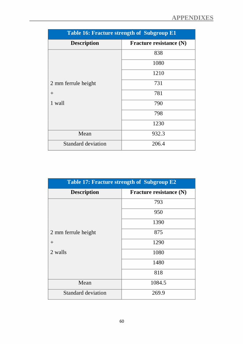
APPENDIXES
60
Table 16: Fracture strength of Subgroup E1
Description Fracture resistance (N)
2 mm ferrule height
+
1 wall
838
1080
1210
731
781
790
798
1230
Mean 932.3
Standard deviation 206.4
Table 17: Fracture strength of Subgroup E2
Description Fracture resistance (N)
2 mm ferrule height
+
2 walls
793
950
1390
875
1290
1080
1480
818
Mean 1084.5
Standard deviation 269.9