the implementation and operation of a variable-response electronic throttle control ... · pdf...
TRANSCRIPT

Ngo "_0086
NASA Technical Memorandum 101696
The Implementation and Operationof a Variable-Response ElectronicThrottle Control System for aTF-104G Aircraft
Bradford Neal and Upal Sengupta
December 1989
National Aeronautics andSpace Administration
https://ntrs.nasa.gov/search.jsp?R=19900010770 2018-05-19T10:46:14+00:00Z


NASATechnicalMemorandum 101696
The Implementation and Operationof a Variable-Response ElectronicThrottle Control System for aTF-104G Aircraft
ii
Bradford Neal and Upal SenguptaAmes Research Center, Dryden Flight Research Facility, Edwards, California
1989
National Aeronautics andSpace AdministrationAmes Research Center
Dryden Flight Research FacilityEdwards, California 93523-5000


CONTENTS
ABSTRACT 1
INTRODUCTION 1
NOMENCLATURE 1
AIRCRAFT AND ENGINE DESCRIPTION 2
THROTTLE SYSTEM DESCRIPTION 2
Mechanical System ............................................ 2
Electronic System ............................................. 3TCU Modes ................................................ 3
Test Signal Inputs ............................................. 4
Instrumentation System .......................................... 4
SYSTEM OPERATION 4
Operating Procedures 4
Typical Mission Profile ........................................... 5
RESULTS AND DISCUSSION 5
CONCLUDING REMARKS 6
REFERENCES 7
TABLES 7
FIGURES 9
°o.
111


ABSTRACT
During some flight test programs, researchers have encountered problems in the throttle response characteristics
of high-performance aircrafL To study and to help solve these problems, the National Aeronautics and Space Ad-
ministration Ames Research Center's Dryden Flight Research Facility (Ames-Dryden) conducted a study using a
TF-104G airplane modified with a variable-response electronic throttle control system. Ames-Dryden investigated
the effects of different variables on engine response and handling qualities. The system provided transport delay,
lead and lag filters, second-order lags, command rate and position limits, and variable gain between the pilot's throt-
de command and the engine fuel controller. These variables could be tested individually or in combination. Ten
research flights were flown to gather data on engine response and to obtain pilot ratings of the various system con-
figurations. The results should provide design criteria for engine-response characteristics. This paper describes the
variable-response throtde components and how they were installed in the TF-104G aircraft. It also describes how
the variable-response throttle was used in flight and some of the results of using this system.
INTRODUCTION
The initial need for the throttle-response-criteria research experiment arose from unsatisfactory throttle responsein the formation flying task of an F-15 aircraft with an early version of the F100 engine model derivative (EMD)
engine (Myers and Burcham, 1984). The AV-8B and F- 18 aircraft have also had throttle response problems. Turbofanengines tend to have slower response characteristics, and digital controls may cause undesirable time delays in
the control loop. Such delays were the cause of pilot induced oscillation (PIO) when close formation tasks were
attempted during the F-15 aircraft test program.
The problem with the F-15 aircraft was corrected by a software change, but it showed the need for criteria to
specify desired engine-response characteristics for future projects. A throttle control system was developed for the
National Aeronautics and Space Administration (NASA) Ames Research Center's Dryden Flight Research Facil-
ity's (Ames-Dryden's) TF-104G aircraft to evaluate the cffect of various throttle system configurations on engine
response. The variable-response throttle system simulated different types of engine response. Parameters were
varied to determine pilot ratings of the different conditions.
NOMENCLATURE
EMD
L/L
LVDT
NASA
PCM
RVDT
TCU
AT
7n
_n
engine model derivative (experimental engine)
lead-lag
linear variable-differential transformer
National Aeronautics and Space Administration
pulse code modulation
rotary variable-differential transformer
throttle control unit
time delay
second-order lag damping ratio
L/L denominator time constant
L/L numerator time constant
second-order lag natural frequency

AIRCRAF]" AND ENGINE DESCRIPTION
The test aircraft was a TF-104G, a high-performance two-seat, trainer-fighter-interceptor airplane designed for
high subsonic cruise and high supersonic combat speeds. Notable features of the aircraft include extremely thin
flight surfaces, short, straight wings with 10° anhedral, and a controllable horizontal stabilizer mounted on top of
the vertical stabilizer. The wings have leading- and trailing-edge flaps, and a boundary-layer control system, used
in conjunction with the trailing-edge flaps to reduce landing speeds. The TF-104G aircraft with the J79-11B engine
was chosen because of its fast thrust response characteristics at all settings.
The J79-11B engine is an axial-flow high-pressure-ratio turbojet engine with variable stators, a single rotor, and
an afterbumer. The guide vanes and the first six rows of stators are varied with engine speed and compressor inlet
temperature for optimum compressor performance.
The TF-104G airplane, NASA tail number 825, has been used by Ames-Dryden for other research projects and
as a support (chase) aircraft. Figure 1 is a photograph of the aircraft.
THROTTLE SYSTEM DESCRIPTION
A contractor developed the variable-response throttle control system (Calspan Corp., 1984), and Ames-Dryden
performed the acceptance testing, modification, and installation of the system (Otto, 1986). The system was designed
for the TF- IlMG aircraft. The experimental electronic throttle control system is driven by commands from a modified
forward-cockpit throttle. The variable-response throttle system consisted of position sensors, an electronic throttle
control unit (TCU), and an integrated servomotor-clutch assembly. The servomotor was connected to the engine
fuel control by a cable linkage. The aft-cockpit throttle control system was left in the production configuration and
was fully mechanical.
Mechanical System
In the production TF-104G aircraft, the forward and aft throttles are physically connected, and both command the
engine using the mechanical control system. The forward and aft throttles are connected directly to the engine fuelcontrol through a conventional cable and pulley system. The two throttle handles are linked so when one throttle
handle is moved, the other tracks its position. In this configuration, the forward and aft throttle handle positionsmatch at all times.
In the experimental configuration, the forward throttle was disconnected from the production system by removing
the linkage connecting the throttle handle to the fuel-control cables. With the linkage removed, the forward throttle
handle no longer tracked the throttle inputs made by the aft pilot. The aft throttle handle, however, still tracked the
throttle inputs made by the forward pilot when the TCU was engaged. This occurred because the aft throttle was
still mechanically connected to the fuel control, which was driven by the servomotor when the TCU was engaged.
When the TCU was disengaged, the servomotor was disabled and the forward throttle had no effect on the aft throttle
position or on engine response. The TCU was located in the left-hand console of the aft cockpit (fig. 2).
With the forward throttle handle disconnected from the cable system, most of the inherent friction on the handle
was eliminated, so the forward throttle handle would not remain in the selected position. An adjustable friction device
was added to the throttle-handle axle to solve this problcm. The device was a small phenolic block and bracket,
mounted in the throttle housing, which created drag against the throttle-handle axle. The device was intended to
be adjustable to any friction level. Even with the friction device installed, however, the throttle stick force was
adjustable only to a maximum of two pounds, approximately one-half of the normal stick force encountered in the
production configuration.

A rotaryvariable-differentialtransformer (RVDT) sensed forward throttle position. It was mounted in the throttle
housing and connected to the throttle handle axle through gears. Figure 3 shows the throttle housing, RVDT, and
friction device assembly.
The linear variable-differential transformer (LVDT) and servomotor-clutch assembly were mounted in the engine
bay. An additional cable was connected between an extra pulley, mounted on the fuel control, and the servomotor.
The LVDT, used to sense the fuel control position, connected to this additional cable assembly. Figures 4 and 5 show
the clutch/servomotor, LVDT, and fuel control setup.
Electronic System
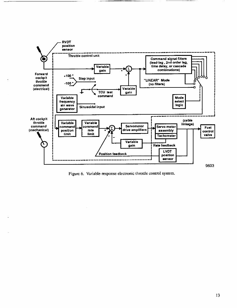
Figure 6 is a simplified block diagram of the throttle control system. The variable-response electronic system
replaced the original cable linkage between the forward throttle and the fuel control. The aft-cockpit throttle, left in
the production configuration, served as a safety backup system.
The electrical signal from the RVDT was entered into the TCU and amplified by a gain factor variable from 0.0
to 2.9. In the normal linear operating mode, the amplified RVDT signal was checked against the TCU settings for
position (amplitude) and rate limits. The signal was compared to the actual throttle position, sensed by an LVDT
tied to the fuel control cable linkage. The error signal, or difference between the RVDT command and the LVDT
feedback signals, was used to advance or retard the servomotor position. The motor was tied to the fuel-control
cable, so its position determined the amount of fuel the engine received. A tachometer on the servomotor assembly
provided a rate feedback to the TCU. The rate feedback gain was adjustable to optimize the damping characteristics
of the electronic control system.
The aft-cockpit throttle-handle linkage to the fuel control was tied to the cable which connected the servomotor
and LVDT with the fuel control. Therefore the LVDT position feedback signal had the same value as the aft-cockpit
throtde position.
Figure 7 shows the TCU control panel built into the front face of the unit's chassis. The control panel was used
to activate the system, set the values of system variables, select the operating mode, and enter test signals. To fully
activate the system, the power switch was placed in the on position and the engage switch pushed up. This provided
power to the TCU and the servomotor, and engaged the clutch that allowed the motor to move the fuel-control
cable. If the clutch was disengaged, the motor continued to spin, but was not connected to the cable. If the motor
was turned off, the clutch automatically disengaged. The standby mode provided power to the TCU only and was
used to check the values of TCU variables prior to fully activating the system in order to avoid transients on initial
system engagement.
TCU Modes
The original goal of the project was to simulate degraded modes of engine response and assess their effects. The
TCU inserted time delays, lead and lag filters, second-order lags, rate limits, and position limits into the command
path. These variables acted directly on the pilot command.
The desired mode was selected by a rotary switch on the TCU control panel. The modes could be tested individ-
ual/y, for example inserting time delays on/y without altering any other parameters. They could also be cascaded,
such as using a time delay followed by a lead/lag filter. The rate and position limits acted on the output signal of thecircuit selected.
The values of the parameters were selected by thumbwheel switches on the control panel. These parameters
included the lead- and lag-circuit time constants (_-,_,ra), second-order lag damping ratio (_), second-order natural
frequency (to,,), length of time delay (A T), maximum-command position limit, and positive and negative command

ratelimits.Theratelimitscouldbeadjustedindependentlyto simulateeffectssuchasanenginethat would increase
rpm at a different rate than it would decrease rpm.
Test Signal Inputs
The TCU had built-in circuits that could be used to generate test input signals. These test signals provided
calibration or reference data on the response characteristics of the different system configurations. There were two
types of test signal inputs available, a step input and a sinusoidal input. The step input could have positive or negative
polarity, and the sinusoidal frequency could be varied from 0.0 to 2.9 Hz. The test signal (step or sine) was entered
into a variable-gain amplifier. The amplitude of the test signal could be varied from 0 to 4-100 ° of throttle angle in
1° increments. The test signal was totaled with the forward pilot's throttle command. As a result, the test circuits
could generate input variations centered around any desired throttle setting.
The aft-cockpit pilot controlled the test functions, like all TCU functions, from the TCU control panel. The pilot
selected the type of signal using a momentary-on toggle switch, normally kept in the off position. The step-input
polarity was also controlled by a toggle switch. The amplitude of the test signal and the sinusoidal input frequency
were adjusted with thumbwheel switches on the control panel.
Instrumentation System
The main component of the TF-104G instrumentation system was a CT-77C pulse code modulation (PCM) data
acquisition system. Analog signals from the TCU, as well as data from sensors on the aircraft, were read by the
aircraft PCM system. The PCM system converted inpuLs into a serial-digital bit stream transmitted to the ground
using a frequency modulation (FM) telemetry transmitter. The telemetered serial PCM data was received on the
ground, decoded, formatted for real-time display on cathode ray tubes (CRTs) and strip charts, and recorded for
postflight analysis.
The CT-77C word length for one digital word was 10 bits. A data frame was one complete transmission cycle
of serial-digital words. The configuration used for the throttle experiment had a total frame length of 80 words (not
all of these were used). The data frame was repeated at a rate of 200 Hz, meaning that each instrumented parameter
was sampled at 200 samples/see.
The measured values of the pressure and temperature parameters were used to generate computed values of
airspeed, altitude, Mach number, static temperature, and standard day temperature (at altitude). These calculated
paramcters were also formatted for a real-time display. Table 1 shows the aircraft and engine parameters measured
for this project. Most of the parameters monitored were input and output signals from the different sections of the
TCU. Table 2 shows the TCU parameters measured for this experiment.
SYSTEM OPERATION
Operating Procedures
The aft-cockpit pilot started the engine for each fight using the mechanically-direct throttle system for safety.
The forward throttle could be used to start the engine, but this was not considered a viable option because of the
possiblility of power interruptions to tile TCU during the change over from ground to internal power.
The frontseat pilot was the experiment evaluation pilot. The backseat pilot controlled the variable-response
system and set the configuration of the system for specific test conditions. The evaluation pilot did not know these
settings during the test flights, allowing an unbiased rating on the handling qualities of the configurations.

Thebackseatpilotcoulddisengage or override the electronic system at any time. The mechanical control system
was always functional from the aft cockpit and operated in parallel with the electronic system when the TCU was
activated. If the TCU was disengaged, the frontseat pilot had no way to control the engine.
As a precautionary measure and to develop system confidence, the aft pilot conducted the taxi, takeoff, and
landing for the first three flights. For these phases of the mission, the TCU was placed in the standby mode but not
engaged, allowing the electronic throttle system parameters to be monitored in the control room but preventing the
forward pilot from controlling the throttle. After the first three flights, confidence in the electronic throttle system
was high enough to allow the forward pilot to conduct all remaining taxi, takeoff, and landing tasks. During these
tasks the electronic throttle system was set to a baseline throttle response, considered to be the best for this throttle
control system.
Once airborne, the TCU was set to the desired test configurations. For the first three flights, the TCU was disen-
gaged and the power brought to standby before changes were made to any of the TCU parameters. This prevented
any uncommanded throttle transients resulting from the change in TCU parameters. Again, once confidence was
established in the throttle control system, it was disengaged only to perform TCU mode changes. After the first three
flights, all thumbwheel parameter changes (fig. 3) were made with the TCU engaged. The pilots knew that small
transients in throttle position might occur, but preferred this to repeatedly disengaging and reengaging the system.
Typical Mission Profile
A typical flight consisted of 10 to 15 test conditions and lasted approximately 1.3 hr. All test conditions were
flown at a target altitude of 15,000 ft and airspeed of 350 kn. At these conditions the TCU was set to the desired
configuration, and the formation flying task was conducted. After each test point the TCU was returned to the baseline
throttle response, allowing the evaluation pilot to regain a feel for the baseline throttle response and providing time
to evaluate the previous test point.
All test conditions were evaluated using a two-phase formation flying task. The first portion of the task was the
gross acquisiton of the formation position on the lead aircraft (an F-18 or T-38 aircraft) and refining that position
to a fine tracking task with no throttle changes by the lead aircraft. After the gross acquisition was refined to the
line tracking task, on call from the evaluation pilot, the lead aircraft began making small, unannounced longitudinal
accelerations and decelerations and shallow bank turns. The evaluation pilot attempted to match these changes.
At the beginning of this program a simulated refueling, using an F-18 or T-38 airplane as a simulated tanker,
was discussed as a possible evaluation task. This task was considered unacceptable, however, because of the lack
of suitable reference points on the lower surfaces of the F- 18 and T-38 aircraft for the evaluation pilot could gauge
his performance by.
RESULTS AND DISCUSSION
Preliminary results show some interesting trends in the relationship between pilot ratings of engine response and
the settings of the TCU. For example, pilot ratings were very sensitive to time delays in the forward command path.
Some design modifications can be suggested, if the project is to be continued or used on another type of aircraft
and engine. Many design choices for the present system were based on cost and time constraints.
The physical construction of the TCU presented problems in repair and maintenance. The unit contained several
printed circuit cards bolted together onto a pressed aluminum chassis. The cards were connected by a flexible ribbon
cable soldered to each card. A more rugged chassis with card slots milled in the sides would allow circuit cards to be
inserted and removed without dismantling the entire unit. This would also permit a modular approach to the design
of the system, allowing certain components to be modified without having to rebuild others.

Theforwardthrottlefrictiondevicealsopresentedproblems.Theamountof friction adjustment available was
extremely limited and the difficulty of adjustment excessive. If the device was more accessible for adjustment and
able to adjust the stick force to at least that of the production TF-104G, the throttle stick force could be one of the
variable parameters in the experiment. In this experiment the throttle stick force was adjusted to its maximum value
and left at that level for the duration of the experiment.
One basic change requested by project personnel was additional output signals from the TCU to allow instrumen-
tation of the power/engage switch positions and of the setting of the sequence select or mode switch. Control-room
personnel could then monitor these settings during flights. The number of radio calls between the ground and theairplane to verify switch settings would then be reduced.
Finally, remote setting of the TCU parameters might be desirable. If the TCU could accept inputs from an
external source and adjust its values for system variables accordingly, a signal could be sent from the ground
to establish test conditions. This would reduce the aft-seat pilot's workload and allow greater flexibility duringflight tests.
At the start of the flight test phase, there was doubt about which type of flying task was best for evaluation of
engine-response criteria. Much of the flight time during the first three flights was used to determine standard tasks
for future evaluations. After these were defined, the test flights were smoother and more efficient. A simulated
refueling task would have been useful as an evaluation condition but would have required the use of tanker and
boom for acceptable evaluation cues. This was beyond the scope and budget of this project.
CONCLUDING REMARKS
A variable-response electronic throttle control system was installed in a TF-104G aircraft. The system was used
to check the effects of different variables, such as time delays and rate limits, on throttle response characteristics.
The experimental throttle control system affected the forward-cockpit throttle. The aft-cockpit throttle was left in
the production configuration and the aft-cockpit pilot controlled the system variables.
The system was tested using fine tracking tasks. The variables were set before each task, and restored to baseline
values after each task was completed. The forward-cockpit pilot then evaluated the performance of the throttle andengine during the task.
The system accomplished the basic tasks required of it. A series of ten flights was conducted over an eight
week period, with no significant operational or maintenance problems. Over one-hundred test points were flown,
in addition to the baseline-step and frequency-response measurements taken for the various system configurations.
The variable-response control system was a valuable tool in the investigation of throttle-response criteria.
Ames Research Center
Dryden Flight Research Facility
National Aeronautics and Space Administration
Edwards, California, February 13, 1989.

REFERENCES
Myers, Lawrence, and Frank W. Burcham, Jr., "Preliminary Flight Test Results of the F100 EMD Engine in an F-15
Airplane," AIAA-84-1332, June 1984.
Calspan Corp., Design, Fabricate, Install Variable Response Electronic Throttle Control System in an F-104 Air-
plane, Technical Proposal 7950, RFP 2PR-OFAP-0011, Dec. 1984.
Otto, William F. Variable Response Electronic Throttle Control System: System Checkout andA cceptance Test Plan,
ETCS TM No. 6, Feb. 1986.
Table 1. Monitored aircraft and engine parameters.
Parameter Range
Lateral acceleration
Normal acceleration
Longitudinal acceleration
Exhaust gas temperatureNozzle area
Engine speed
Static pressure
Total pressure
Total temperature
:k:0.25 9
-1 to+3 9
-bl 9415 to 749 °C
280 to 660 in2
0 to 9999 rpm
5 to 80 in. Hg
5 to 80 in. Hg-100 to + 150 °F
Note: TF-104G aircraft throttle angle
settings are as follows:
Idle power = 11-13 °
Military power = 72-74 °Maximum afterburner = 113 °

Table 2. Monitored TCU parameters.
Parameter RangeForward throttle command
Command gain
Throttle position feedback
Position error signal
Test circuit output
Test gain
Test signal frequency
Forward throttle plus Test command
Second-order lag circuit output
Second-order lag damping (if)
Second-order lag natural frequency
Lead-lag circuit outputNumerator time constant
Denominator time constant
Time delay circuit output
Time delay setting
Servo clutch advance signal
Servo clutch retard signalServomotor rate feedback
Selected TCU output command
TCU command position limitPositive rate limit
Negative rate limit
Oto 113 °
0.0 tO 2.0
0tO 113 °
4-100 °
4-100 °
0.0 tO 1.0
0.0 tO 2.0 Hz
0to 113 °
0to 113 °
0.40 to 0.99
5.0 to 9.9 rad/sec
0 to 113°
0.0 to 3.9 sec
0.0 to 3.9 sec
0to 113 °
0 to 1.98 sec
0tO 10V
0to 10V
0 to 100 percent
0to 113 °
13 to 113 °
l0 to 99 deg/sec
- 10 to -99 deg/sec
8

Figure1. TheTF-104Gaircraft.
EC80 12366
Figure 2. TCU installation in the aft cockpit.

Figure 3. Forward throttle assembly.
19
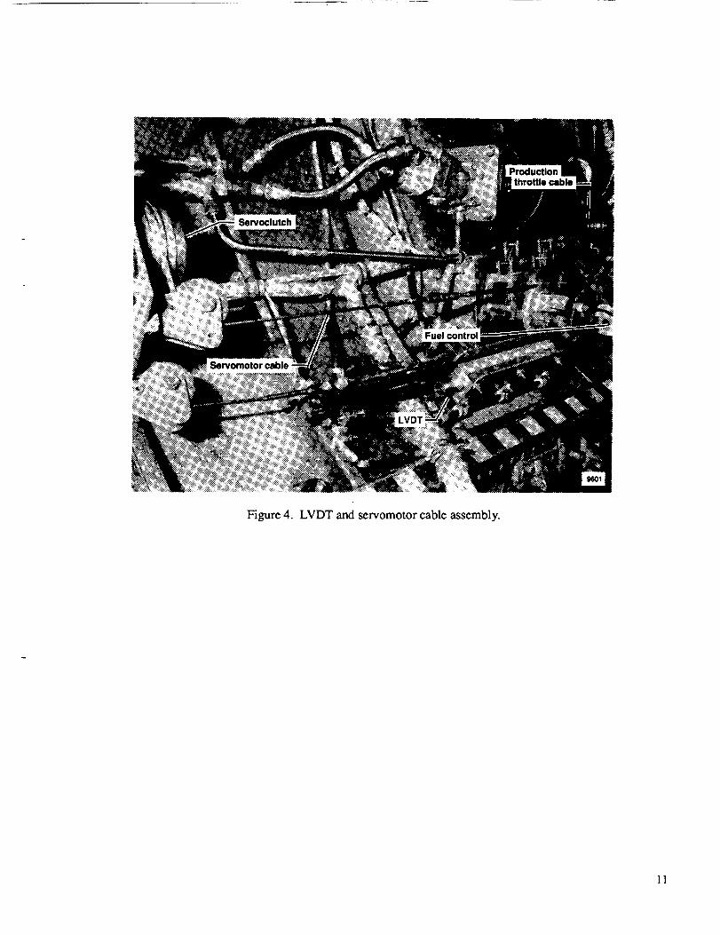
Figure 4. LVDT and servomotor cable assembly.
11

Figure5. Servomotorand clutch assembly.
12
RVDT
_ position
sensor
[ Throttle control unit
Forwardcockpitthrottle
command(electrical)
Aft cockpitthrottle
command
(mechanical)
)
+11111°
0._ Step input,-10 _ I_
-_- -_-TCU testcommend
Variable
frequencysin wave
generatorSinusoidel input
Variable Variablecommand command
position ratelimit limit
Commend signal filters(lead-lag, 2nd order leg,
time delay, or cascadecombinations)
o,IIIII
Servomotordrive amplifiers
Variable
gain
_ition feedback
"LINEAR" Mode
(no filters)
(cablelinkage)
motor
assembly
Tachometer
I Rate feedbackIII
Figure 6. Variable-response electronic throttle control system.
9603
13

FIB BD I717\
G//2ND ORDER LAG _n
FIN FID i-qlq/AT SX MAX COMMAND GAIN
DELAY POSITION LIMIT . .....................
rqFI FIR __+ _ L ..................................._RATE LIMIT lax MAX) 9) ON _
- Thumbwhselswltchseused to setcontrol
systemvariableparameters
Red LEDIndicatespower to8013/0-
AT ..... Yellow LED
TEST ...... _ STBY _ Indlcates," r- _o_ /- , -ow.r/ENGAGE I SIN '_'" I _ _ _ 2ND'AT ON I r2 .,l.,e._,,
/ o,s STEP/,.,E_ ,.,,/\\.T._.Oo_ only
Z Re_D ENG:G:; I ZS:lp._PUnt sPo,trtt y_ Sc_lhUoe;:: I_I_1 :t o_W'_:_ht,on
servoclutch ] s ff hhas been Ipowered I
L Momentary contact switch allowsselection of test Input signals
96O4
Figure 7. TCU control panel.
14


Report Documentation PageS_aceA_nw_a_n
1. Report No.
NASA TM-1016964. Title and Subtitle
2. Government Acceuion No. 3. Recipient's Catalog No.
5. Report Date
December 1989The Implementation and Operation of a Variable-Response Electronic
Throttle Control System for a TF-104G Aircraft
7. Author(s)
Bradford Ncal and Upal Sengupta
9. Performing Organization Name and Address
NASA Ames Research Center
Dryden Flight Research FacilityP.O. Box 273, Edwards, CA 93523-5000
12. Sponloring Agency Nm end Addre_
National Aeronautics and Space Administration
Washington, DC 20546
6. Performing Organization Code
8. Performing Organization Report No.
H- ] 54210. Work Unit No.
RTOP 307-07-00011. Contract or Grant No.
13. Type of Report and Period Covered
Technical Memorandum14. Sponsoring Agency Code
1,5. Supplefr_ntary Notes
16. Abstract
During some flight test programs, researchers have encountered problems in the throttle response character-
istics of high-performance aircraft. To study and to help solve these problems, the National Aeronautics and
Space Administration Ames Research Center's Dryden Flight Research Facility (Ames-Dryden) conducted a
study using a TF-104G airplane modified with a variable-response electronic throttle control system. Ames-
Dryden investigated the effects of different variables on engine response and handling qualities. The system
provided transport delay, lead and lag filters, second-order lags, command rate and position limits, and vari-
able gain between the pilot's throttle command and the engine fuel controller. These variables could be
tested individually or in combination. Ten research flights were flown to gather data on engine response and
to obtain pilot ratings of the various system configurations. The results should provide design criteria for
engine-response characteristics. This paper describes the variable-response throttle components and how
they were installed in the TF-104G aircraft. It also describes how the variable-response throttle was used in
flight and some of the results of using this system.
17. Key Wordl (Suggested by Author(=))
Digital Control Systems
Engine Throttle Control Systems
Throttle response
19. Security Clauif. (of this report)
Unclassified
NASA FORM 1828 OCT 88
18. Distribution Statement
Unclassified -- Unlimited
Subject category 07
20. Security Classif. (of this page)
Unclassified
21. No. of pages 22. Price
18 A02
*For sale by the National Technical Information Service, Springfield, VA 22161-2171.

