the impedance of a monopole antenna with a circular ... of research of the notional bureau of...
TRANSCRIPT

JOURNAL OF RESEARCH of the Notional Bureau of Standards-D. Radio Propa ga tion Vol. 65D, No.2, March-Apri l 1961
Inlpedance of a Monopole Antenna With a Circular Conducting-Disk Ground System on the Surface of a Lossy Half Space l
S. W. Maley and R. J. King
(Sep tember 27 , 1960 ; revised D ecember 1, 1960)
T he base imp edance of a A/4 monopole antenna w it h a circular condu cting dis k grou nd ~ystem on t he surface of a l ossy ha lf-space is calculated as a fu nct ion of di s k diamete r using th ree d iffe rent approximate met hods. Ve rify ing m easu rements were made on a mod el at X-band frequ encies by simulat ing the lossy ha lf-space wi t h a wate r fill ed tank sufficiently large to approximate t he res ul ts expected from a n infini te lossy ground . The meas ured impeda nce values, Z, were br oken up i nto t he sum of two te rms t:.Z and Zoo w he re Z oo i th e impedance of t he a ntenna with a pe rfectly condu cting g rou nd a nd t:.Z is a te rm which accounts for t he fi nit e size of t he di s k . T he expe ri mental rneas urements 0 11 a number of GLn tcllnas indi cate t hat t he ratio t:.Z/Z oo as a fu nction of dis k di amete r is nead y t he sarn(' fo r ",11 ",ntennas m eas u red . Co mparison of t he m.eas ured "",Ill es of t his nLt io " Ild t he values ca lcul ",tcd by t he th ree d ifl"e rent app rox imate m.et hods indi cate q ua li tat ive agree m.en l.
1. Introduction
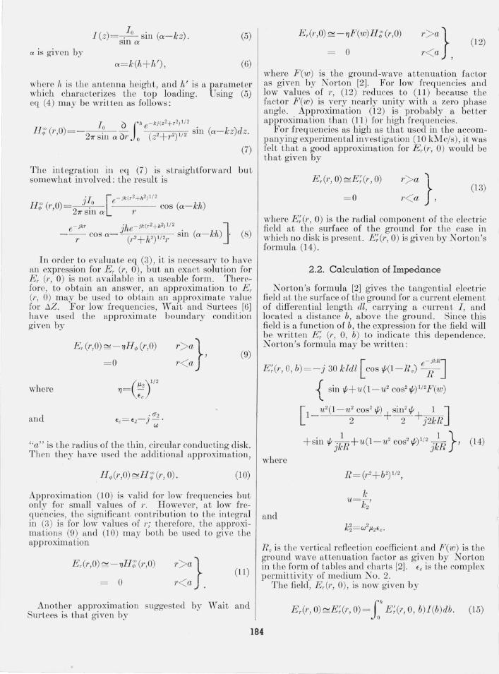
This p,tper presents ,1, theoreticfll fl nd exp erimental invcstiga tion of t he impedance of a vertical monopol e w it h a t hin, circular , co ndu ct ing disk ground system on the s urface of a lossy half sp itce as r eprese nted ill fi g ure l. The monopole impeda nce WflS calcul ated using t hree different m ethods and was exp erimen taJly m eas ured for ante nn a heig llt n ear on e-quar ter wavel ength and for a range of valu es of disk: d iam ete r . Th e investigaLion was n1<Lde aL X-ba nd frequ encies Lo permi t t he experimental work to b e done in th e laboratory under carefully co ntrolled condition s. Th e lossy h alf sp ace was s imula ted bv use of a wa tcr-fi llcd tank abou t 120 WH.velength s·squ are. T he calculated a nd measured val ues of impeda nce have becn plotted on t he same char t to permit comlJ~1,riso n .
2 . Impedance Calculations
2 .1. Formulation of Impedance -
Th e b ase impedance of the monopole antenn a system r epresentee! in fig ure 1 is ealcula ted using
F i I
MONOPOLE ANTENNA I , I
" I h CI RCULAR DISK _ " j'-"~ MEDIUM NO I ( ) ' \ ......... . jJ.o,~o
IMPERFECT " ".f!, \ "
GROUND, :- -,"~ -- o-- 1/1 f"', WW"$~aJ)Pp);ffiY)$))))M~----~-
MEDIUM NO.2 ( J1- z' ' 2' (J z )
F JG L' RE I . Jl ron01Joie antenna with a circular condu cting disk ground system on the surface oj a lossy half-space.
1 Contri bution from Engineering E xperiment Station , Uni\"(~ rs i ty of Co lorado, Doulder , Colo. '11 hc work reported here was supported by the Electronics R esearch Direct orate or tho U. S. Air Force Cambrid ge Rt'search Cen ter.
574930-61--6
t hree difl'crenL ~1, pproxima te m ethods. Due to t he symmetry of the co nfigumtion a cylindri ct1,l coorcli nate sys tem is Llsed ma,king t l1C field expressio ns indep ende nt of the az imuthal coord inate r/>.
Jt is co nvenient to expres th e m agnet ic field , IT", (r,z) in t he form .
IJ", (1', z) = 11; (1', z) + TJJ,(r, z) . (1)
The s uperscript "co" denotes t he field t hat wo uld exist if t he ground wer e p erfectly co nducting, w hile s uperscrip t "s" denotes t he difrercnce betwee n t he actual fi eleL a,nd tiJ e fi eld t h,1,t would exist for a p erfectly conducting g ro und . VVe also express Lhe <tn Lenn a impeda nce :0 in a simihu m a nn er :
(2)
H ere again the s uperscrip t " co" denote th e imp edan ce fOT a pe rfectly co ncl ucting ground, and 6:0 is th e d iffer ence between Lh e actual imp edance ,tnci t he impedance for ,t perfectl.\' co ndu cting ground .
As is shown by W ait ,wd P ope, [5] 2 the cha nge in imped~LIl ce, 6Z , ma~r be expressed as
6Z=-~ fa '" H ; (1', 0)Er (r, 0)27f l'dr. (3)
H ;(r ,O) is given by t he expression
(4)
Ln this expression, 1 (z) is t he curren t in the fl ll tenna as a fun ction of z, and 10 is the m agni tude of t he b ~tse current. The ante nna is assumed to be thin fwd t her efore t he a n ten ntt current m ay be assumed. r eal and sinu soidally distribu ted . Thus we have
2 Figures in brackets indicate the literature references at tho end or this pa per.
183
I (z)=-J2-sin (a-kz). SIn a
(5)
a is given by a= k (h+ h' ) , (6)
where h is tbe antenna beigbt, and h' is a parameter which ch aracterizes the top loading. Using (5) eq (4) may be written as follows :
The integration in eq (7) is straightforward but somewhat involved: the r esult is
Ff; (1' ,0)
(8)
In order to evaluate eq (3), it is n ecessary to h ave an expression for E r (1', 0), but an exact solution for E r (1', 0) is not available in a useable form. Therefore , to obtain an answer, an approximation to Er (1', 0) may be used to obtain an approximate value for t.Z. For low frequencies, Wait and Sur tees [6] have used the approximate boundary condition given by
E r (1', 0) ~- TlFfq, (1', 0) (9)
= 0
where
and
"a" is the radius of the thin, circular conduc tillg disk:. Then they h ave used the additional approximation,
(10)
Approximation (10) is valid for low frequencies but only for small values of r. However , at low frequencies, th e significan t con tribution to the integral in (3) is for low values of 1'; therefore, t he approximations (9) and (10) m ay bo th be used to give the approxim ation
E r(r ,O) ~ - TIFf; (1' ,0)
° (11)
Another approximation suggested by Wait and Sm-tees is that given by
Er(r,O) ~ - TlF (w) H ; (1', 0)
° (12)
where F(w) is the ground-wave at tenuation factor as given by N orton [2]. For low frequen cies and low values of 1', (12) r educes to (11) because the factor F(w) is very nearly unity with a zero phase angle. Approximation (12) is probably a better approximation than (11 ) for high frequencies.
For frequencies as high as that used in the accompanying experimental investigation (10 kMc/s), it was felt that a good approximation for E r(r, 0) would be that given by
= 0 }, (13) E r(r, 0) ~E;(r, 0)
where E;(r, 0) is the radial component of the electric field at the surface of the ground for the case in which no disk is present . E;(r, 0) is given by N orton's formula (14) .
2.2. Calculation of Impedance
Norton's formula [2] gives th e tangential electric field at the surface of the ground for a current element of differential length dl, carrying a cm-rent 1, and located a distance b, above the ground. Since this field is a function of b, the expression for the field will b e written E; (1', 0, b) to indicate this dep endence. N orton's formula m ay be written :
E ;(r, 0, b)= -j 30 kIdl [ cos 1/t(I - R v) e~kRJ
{ sin 1/t+ u(1-u2 cos21/t)1/2F (w)
[ 1 1t2( I -u2 cos21/t) sin21/t 1 ] 2 + - 2- +j2kR
+ sin 1/t j~R+U(1-U2 cos21/t)1/2 j~R } ' (14)
where
k U=-,
k2 and
Ro is the ver tical reflection coefficien t and F( w ) is th e ground wave attenuation factor as g iven by Norton in th e form of tables and charts [2]. f c is the complex permittivity of medium No.2 .
The field, E r(r, 0), is now given b y
(15)
184
The complcxity of the expressions for E; (1', 0, b) makes it necessary to evaluate the integral in (15) numerically. This integral must be evaluated for each value of l' that is r equired. Since Er (1', 0) must be obtained by a numerical integration, eq (3) for ilZ mu t also be evaluated by a numerical integration. The inLegral in (3) was approximated by a sum over a finite range of values of 1'; then a constan t was added to correct for the use of the finite range for l' rather than an infinite range. I t was found that this constan t could be evaluated to a high degree of accuracy. Using this method it was found that the integrations in eqs (3) and (15) can be carried out numerically to an adequate degree of accuracy without a prohibitive amount of work. These calculations have been made for a quarter-wave monopole at 10 kMc/s for the case in which medium No . 2 is water. T he complex dielec tric constant used for water was €c= 49- j34. The impedance ilZ was also calculated for the same an tenn a and the same frequency, using the approximations (11 ) and (12).
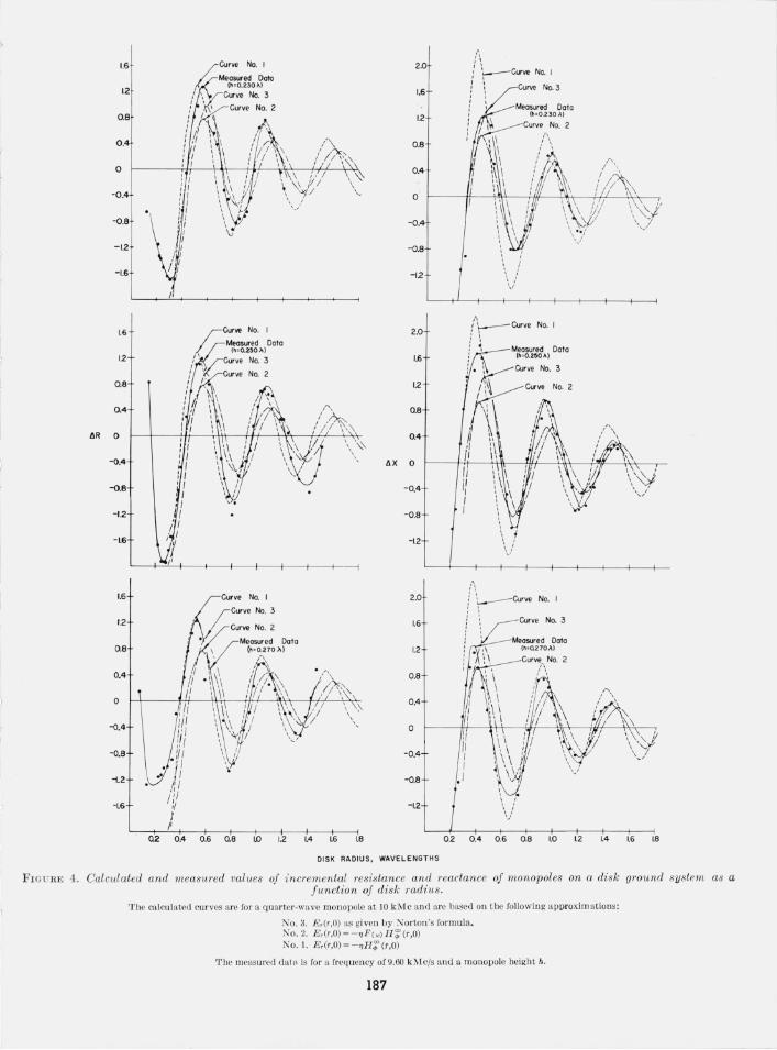
The results of the calculations for all three approximat ions arc shown along with the measured values, in figure 4. The resistive and reactive components of ilZ arc plotted as functions of disk radius in wavelengths.
3 . Construction of the Experimental Equipment
A large 12 ft x 12 ft x 4 in. plywood water tank (117 wavelengLlls square at 9.60 kMc/s) was held aloft so that the impedance measuring equipment could be placed directly beneath the monopole posit ion eet at the tank cenLer . It is anLicip aLed LhaL the finite size of the Lan Ie cn,uses insignificant elTOl' because identical meas uremen ts were m ade w'ith a tank roughly half the size of the one used here.
The monopole was fed by a 5011 rigid air-coaxial line 0.620 in. in length which m ade a trans ition into 8 in. of 4811 rigid air-coaxial line. The latter was in tum connected into a coaxial slotted section with a standard type " N " connector. A micrometer eq uipped probe carri age then provided a means of measuring the standing wave pattern position with a tolerance of ± 0.001 cm.
The short section of 5011 air-coaxial line used a replaceable center conductor which plugged into the 4811 line center conductor . Various lengths of the monopole (an extension of the center conductor) could t hen be interchanged without disturbing the coaxial feed system . A single supporting teflon bead 0.020 in. long was fastened approximately midway
) in the 5011 air-coaxial line. The inside diameter O~ in. ) of the monopole feed line was made as small as machining considerations would allow, thereby better approximating a "thi:n" antenna and a "poi:nt" feed, and providing a very high attenuation (75 .3 db/cm) for the TEll mode of propagation.
SLability considerations required that the 4811 line be as rigid as possible, thus allowing the monopole to be raised and 10'wered without disturbing the system calibration. For these same reasons, the number of mechanical joints was kept to a minimum.
50 JL AIR COAXIAL FEED LINE
+-48 JL AIR COAXIAL LINE
J <
MONOPOLE
~APEREO ADAPTER
(press fit)
TEFLON SUPPORTING BE ADS
TO TYPE .. N" CONNECTOR a COAX IAL SLOTTED SECTION
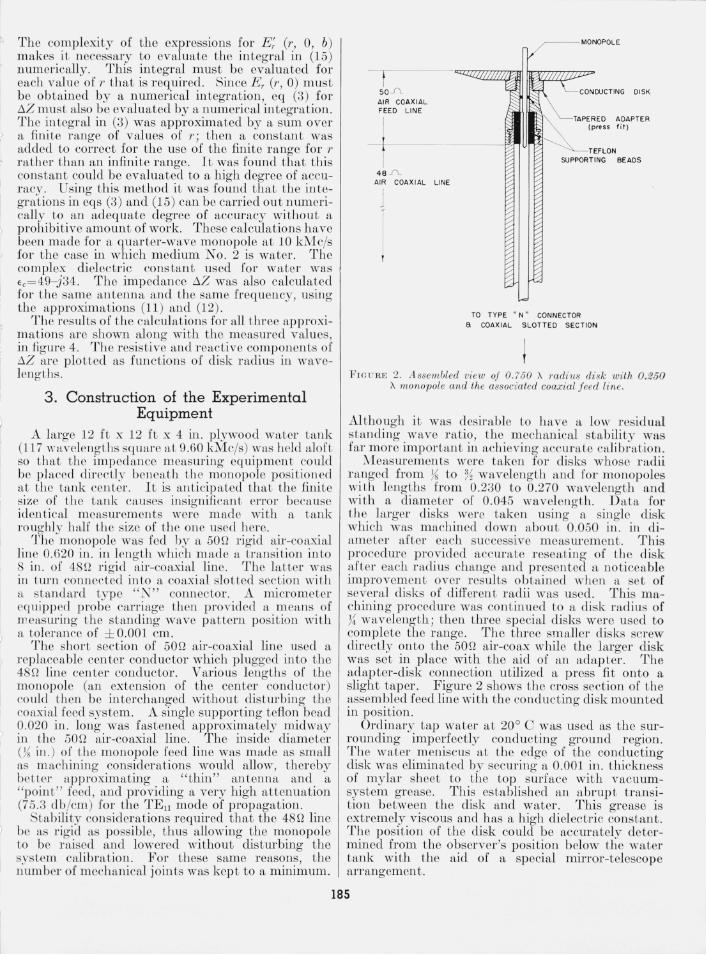
FIC am ;; 2. A ssembled view of 0. 750 A mdills d'isk with 0.250 A monopole and the associated coaxial f eed line.
Although it was desirable to have a low residual standing wave r atio, the m echanical stab ili ty was far more important in achieving accurate calibrat ion.
:Measurements were taken for disks whose nt.dii ranged from ?~ to % wavelength and for monopoles with lengths from 0.230 to 0.270 wavelength and with a diameter of 0.045 wavelength. D ata for t il e larger disks were taken using a single disk which was machined down abou t 0.050 in . in diameter after each successive measurement. This procedure provided accuraLe reseaLin a of the disk after each r adius change and presented a noticeable improvemen t over resul ts obtained wh en a se t of several disks of different radii was used. This machining procedure was continued to a disk radius of 7~ wavelength ; then three special disks were used to complete the range. The three smaller disks screw directly onto the 50n air-coax while the larger disk was set in place with the aid of an adapter. The adapter-disk connection utilized a press fit onto a slight taper. Figure 2 shows the cross section of the assembled feed line with the co nducting disk mounted in position.
Ordinary tap water at 20° C was used as the surrounding imperfectly conducting ground region. The water meniscus at the edge of the conducting disk was eliminated by securing a 0.001 in. thickness of mylar sheet to the top surface with vacuumsystem grease. This established an abrupt transition between th e disk and water. This grease is extremely viscous and has a high dielectric constant. The position of the disk could be accurately determined from the observer 's position below the water tank with the aid of a special mirror-telescope arrangement .
185
4. Experimental Results
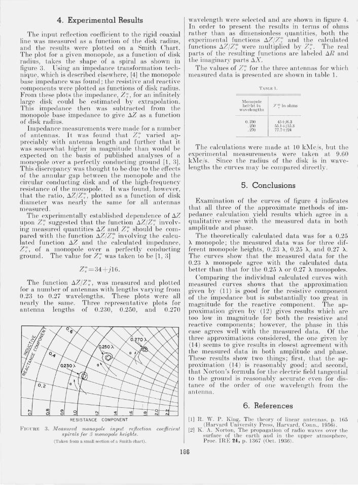
The input reflection coefficient to the rigid coaxial line was measured as a function of the disk radius, and the results were plotted on a Smith Chart. The plo t for a given monopole, as a function of disk radiu s, takes the shape of a spiral as shown in figure 3. Using an impedance transforma tion technique, which is described elsewhere, [4] the monopole bas e impedance was found ; the resistive and r eactive components were plotted as functions of disk radius. From these plots the impedance, Z ,;; , for an infinitely large disk could be estimated by extrapolation. This impedance then was subtracted from the monopole base impedance to give t:.Z as a function of disk radius.
Impedance measurements were made for a number o r antennas. It was found that Z; varied appreciably with antenna length and fur ther that it was somewhat higher in magnitude than would be exp ected on t he basis of published analyses of a mon0pole over a perfectl.v condncting ground [1, 3]. This discrepancy was thought to be due to the effects of th e annular gap between the monopole and the circular conducting disk and of the high-frequency resistance of the monopole. It was Jound, however, that the ratio , t:.Z jZ ; , plotted as a function of disk eliameter was nearly the same for all antennas measured.
The experimentally established dependence of t:.z upon Z; suggested that the function t:.Z jZ ; involving n'leasured qu antities t:.Z and Z; should be compared with the function t:.Z jZ'; involving the calculated fun ction t:.Z and the calcul ated impedance, Z: , of a monopole over a perfectly cond ucting ground . The value for Z '; was taken to be [1, 3]
Z :=34 + j16.
The funct.ioll t:.Z jZ ; , was m easured and plotted for a number of antennas with lengths varying from 0 .23 to 0.27 wavelengths. These plots were all nearly th e same. Three representative plots for f\,ntenna lengths of 0.230, 0.250, and 0.270
RESISTANCE COMPONENT
FIG1TRE 3. JVfeasw·ed monopole input Tejleci1:on coe.fficient spimis JOT 3 m on opole heights .
(T aken from a small secti on of a Smith char t).
wavelength were selected and are shown in figure 4. In order to present the r esults in terms of ohms rather than as dimensionless quantities , both the experimen tal function s t:.7 j7; and the calculated functions t:.ZjZ~ were multiplied by Z~. The real parts of the resulting functions are labeled t:.R and the imagin ary par ts t:.X.
The values of Z; for t he t hree antennas for whieh measUl'rc1 data is presen ted are shown in table 1.
Monopole hei'!h t in 7 ~ in ohms
wa.velen gths
0. 230 45+j6.3 . 250 55.1+j15.3 . 270 77. H j 24
The calculation s were m ade at 10 kMcjs, but the experimental measurements were taken at 9.60 kMcjs . Since the radiu s of the disk is in wavelengths the curves may be compared directly .
5. Conclusions
Examination of the curves of figure 4 indicates that all three of the approximate methods of impedance calculation yield results which agree in a qualitative sense with the measured data in both amplitude and phase.
The theoretically calculated data was for a 0.25 A monopole; t he measured data was for three different monopole heights, 0.23 A, 0.25 A, and 0.27 A. The curves show that the measured da ta for the 0.23 A mOJlopole agree with the calculated data better than that for t he 0.25 A or 0.27 A monopoles.
Comparing the individual calculated curves with measured curves shows that the approximation given by (11) is good for til e resistive component of the impedance but is substantially too great in magnitud e for the reactive compon en t . The approximation given b.'~ (12) gives r esults which are too low in m agnitude for both the r es istive and reactive components ; however , the phase in this case agrees well with the measured data. Of the three approximations considered, th e on e given by (14) seems to give results in closest agreement with the measured data in bo th amplitude and phase. These results show two things; fiTst, that the approximation (14) is reasonably good ; twd second, that N orton's formula for th e electric field tangential to the ground is reasonflbl)~ accurate even for distance of th e order of one wavelength from the antenn a.
6 . References
[ .I ] R. w. P . King, The theory of linea r an tenna s, p . 165 (Harva rd Uni versity Press, H a r vard , Con n., 1956) .
[2] K . A. N orton, The propagation of rad io \va\'es ove r the s urfa ce of the ear th a lld in t he uppe r a tmospherp, Proc. IRE 240 , p. 1367 (Oct. 1936) .
186
I.S
1.2
0 .8
0 .4
0
-0.4
-0.8
-1.2
-I.S
1.6 ;;ClXve No. I Measured Octo
(h : O. 2~O>' )
1.2 " I k::curve No. :3 , , / Kcur ve No. 2
0 .8 ' / . I ~
: f '" \ I Ii "
0.4 ' 'I \ \ i I 'I '\
/lR 0 r I \ ,\
-().4
-0.8
-1.2
-I.S
I.S Curve No. I
1.2
0.8
0.4
o
-().4
-0.8
-1.2 .. -LS
0.2 0.4 O.S 08 1.0 12
2.0
I.S
1.2
0.8
0.4
0
-0.4
-0.8
- 12
2.0
I.S
1.2
08
, 0.4 \'~
/I X 0
-0.4
-0.8
-1.2
--/
2.0
1.6
1.2
0 .8
:- 0.4
0
-0.4
-0.8
-1.2
1.4 I.S 1.8
DISK RADIUS , WAVELENGTH S
/; , ' I'
\:_, _ - Curve No. I
Curve No. 3
Measured Data
0.2 0.4 0.6 0.8 1.0 1.2 1.4 I.S 1.8
FrG URE 4. Calculated and measured values of incremental res'istance and reactance oj monopoles on a disk ground system as a function of disk radius.
The calcul ated curves are for a quarter-wave monopole at 10 kNI c and arc based on the fo llo\ving aporoximations:
No.3. E r(r,O) as given by Norton's formula. No.2. E ,(r,O)=-"F (w) H ';(r,O) No. !. E,(r,O)= -"H';p(r,O)
The measured dat" is for a frequency of 9.60 kMc/s and a monopole height h.
187
~,
[3] S. Ramo and J . R . vVhinnery, Fields and waves in modern radio, p . 546 (John Wiley & Sons, Inc., New York, N .Y ., 1953).
[4] Scientific Report ERD- TN- 60- 763, Impedance and patt ern studies of disk-based monopoles over lossy ground surfaces, E lectron ics Research Directorate, Air Force R esearch Division, Air Research and D evelopment Command, July 1960, Contract No . AF 19 (604)-4556.
[5] J . R. Wait a nd W. A. Pope, The chara cteristics of a vertical antenna with a radial condu ctor ground system, Applied Scientifi c Research, B 4, 177 (1954) .
[6] J. R. Wait and W . J. Surtees, Impedance of a top loaded antenna of a rbitra ry length over a circular grounded screen, J . App!. Phys. 25, 553 (1954) .
(Paper 65D2- 1l8)
188