a multistate frequency reconfigurable monopole...
TRANSCRIPT
856 IEEE ANTENNAS AND WIRELESS PROPAGATION LETTERS, VOL. 18, NO. 5, MAY 2019
A Multistate Frequency Reconfigurable MonopoleAntenna Using Fluidic Channels
Aditya Singh , Ian Goode , and Carlos E. Saavedra
Abstract—A reconfigurable microstrip monopole antenna thatuses three closely spaced substrate milled channels filled with eitherair or dielectric fluid is presented. Based on the number of chan-nels filled with fluid, four states—namely states 0, 1, 2, and 3—ofoperation are selected. Introduction of fluid (distilled water) in thechannel modifies the effective permittivity of the dielectric mediumand perturbs the E-field distribution in vicinity to the antennaarm. The position and size of channels are optimized to maximizethe shift in operating frequency and S11 < −10 dB impedancebandwidth through full-wave electromagnetic (HFSS) simulations.A prototype of the antenna is fabricated and measured, exhibit-ing frequency shifts of 12.0%, 17.9%, and 23.7% with impedancebandwidth of 32.0%, 30.1%, and 29.9% in states 1, 2, and 3 of theantenna, respectively. The reference state, i.e., state 0, offers 34.7%impedance bandwidth. The measured peak gains achieved are 2.4,1.6, 1.2, and 0.3 dBi for states 0, 1, 2, and 3, respectively. In allthe states of operation, the radiation pattern remains stable andomnidirectional.
Index Terms—Antennas, dielectric fluid, distilled water, fre-quency tuning, high-power, microfluidics, microstrip monopole,microwaves, reconfigurable, tunable, wearables.
I. INTRODUCTION
R ECONFIGURABLE antennas are envisioned as one of thekey components in realizing modern-day wireless links for
applications such as cognitive radio [1]. Efficient utilization ofavailable spectrum calls for tunable microwave front ends tosense the communication channel and switch to available fre-quency band [2]. The use of fluids in microwave componentsand antennas for tuning and reconfigurability has sparked wideinterest because of their compatibility with wearable electron-ics, their power handling capability, low-noise behavior, andtheir long lifespan compared to microelectromechanical systemtechniques [3], [4]. Numerous recent works have employed liq-uid metal such as mercury and eutectic gallium indium alloy(EGaIn) to design antennas with reconfigurability in frequency[5]–[7], polarization [8]–[10], and radiation pattern [11]. Liquidmetal can serve applications demanding flexibility, high averagepower, and linearity requirements. However, liquid-metal-baseddesigns face critical challenge in antenna integration and suffer
Manuscript received February 8, 2019; accepted March 4, 2019. Date of pub-lication March 8, 2019; date of current version May 3, 2019. This work wassupported in part by a grant from the Natural Sciences and Engineering Re-search Council of Canada (NSERC). The work of A. Singh was supported inpart by the Trillium Scholarship from the Government of Ontario. The work ofI. Goode was supported in part by the Ontario Graduate Scholarship. (Corre-sponding author: Aditya Singh.)
The authors are with Department of Electrical and Computer Engineering,Queen’s University, Kingston, ON K7L 3N6, Canada (e-mail:, [email protected]; [email protected]; [email protected]).
Digital Object Identifier 10.1109/LAWP.2019.2903781
from problems like stiction and leftover metal oxidation. Differ-ent types of treatments are required to overcome these issues,which is an active area of research [12], [13]. An alternative wayfor tuning planar antennas consists of using dielectric fluids toalter antenna characteristics. Typically, fluids are selected basedon dielectric constant and loss tangent. Various combinations ofantenna geometry and fluids have been explored. In [14], slotantenna with microfluidic channels patterned on polydimethyl-siloxane is proposed. Liquid dielectric contained in the channelsis used to perturb the E-field on a slot antenna resulting in fre-quency tuning but with a narrow bandwidth, low efficiency, andneed for different types of fluids to realize variable effectivepermittivity for tuning. A microfluidic cavity placed on top ofthe radiating edge of a coplanar patch antenna and injected withethanol, hexanol, and water is reported in [15]. A maximumfrequency shift of ∼13% is observed when loaded with water.Furthermore, some nonplanar designs have also been proposed.A flexible membrane-based cavity is enclosed below the antennaand pumped with ethyl acetate in [16] to achieve continuous fre-quency tuning with best simulated efficiency of 69% and 6.8%bandwidth. Moreover, a hybrid layer with tunable height ratio ofair to liquid is used as substrate below a patch in [17]. It employslow-loss transformer oil to extract better efficiency with contin-uous tunable frequency range with limitation of being nonpla-nar. Water has also been employed to provide radiation patternreconfiguration [18] and polarization reconfiguration as in [19].Recently in [20], a wideband microstrip monopole water-loadedantenna with a water-filled channel for frequency switching ispresented. However, only two states are available for operationof the antenna.
In this letter, a microstrip-fed monopole antenna with threesubstrate milled channels orthogonal to length of monopole isproposed. Distilled water filled in the channels is used to modifythe effective permittivity and to perturb the E-field distributionbeneath the monopole arm, resulting in frequency reconfigura-bility with good tuning range and efficiency.
II. FLUIDIC ANTENNA DESIGN
Fig. 1 shows a diagram of the proposed monopole antennaand the backside fluidic channels, including the design parame-ters and dimensions. The basic monopole follows the structurein [21], but here it has been redesigned for a 1.52 mm thickRogers-4003 substrate (εr = 3.38, tan δ = 0.0027) to radiate ataround 5.6 GHz with a 35.5% −10 dB impedance bandwidth(IBW). The length of the monopole arm is set to λg/4, where λg
is the guided wavelength in microstrip environment [22]. Thebottom metal layer serves as the ground plane for the feedline
1536-1225 © 2019 IEEE. Personal use is permitted, but republication/redistribution requires IEEE permission.See http://www.ieee.org/publications_standards/publications/rights/index.html for more information.
SINGH et al.: MULTISTATE FREQUENCY-RECONFIGURABLE MONOPOLE ANTENNA USING FLUIDIC CHANNELS 857
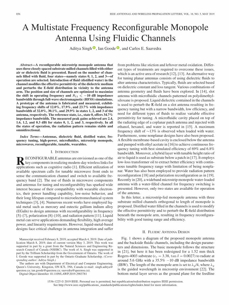
Fig. 1. Microstrip monopole antenna. (a) Front view (dashed lines showchannels on back side). (b) Back view without back cover. (c) Cross-sectionalview in state 2: Lg = 20 mm, Lt = 20 mm, Lm = 8.7 mm, Wg = 30 mm,Wm = 3.2 mm, hbc = 1.52 mm, wbc = 10 mm, hs = 1.52 mm, lg = 4 mm,gc = 0.64 mm, lc = 27 mm, hc = 1.0 mm, and wc = 1.08 mm.
and monopole. The ground plane size and arm width are opti-mized for the best IBW in state 0 through simulations on ANSYSHFSS. Ground plane size was further optimized and chosen as(0.61λg × 0.92λg at 5.5 GHz) to achieve an omnidirectionalradiation pattern [21] and compact size.
For fluidic tuning, three open channels were created on theback side of the antenna by partially milling out the substratebeneath the monopole arm as shown in Fig. 1(b). Another pieceof the same substrate is attached to the back side of the antennausing a hot-melt glue gun to create cuboid-shaped closed chan-nels. As a result, one end of each channel remains open to beused as an inlet/outlet port as shown in Fig. 1(c). The width ofthe channel and the gap between the channels have been inten-tionally chosen to optimize the frequency shift and allow forin-house fabrication with an LPKF ProtoMat circuit plotter.
The antenna’s resonance around λg/4 shifts slightly down-wards when the substrate material below the monopole arm isremoved to simulate air-filled channels. Since another substrateof the same thickness is added on the back side, this results indownward resonance shift as the effective permittivity exhib-ited due to combined effect of two substrates and air may behigher. For reconfigurability, the air channels are filled with dis-tilled water. The dielectric constant and loss tangent for water aremodeled by using the experimentally verified data (εr ∼ 74.6and tan δ ∼ 0.12 at 3 GHz) from [23] with piecewise linearinterpolation between the frequency range of interest. This in-troduces discontinuities in the modified medium owing to highrelative permittivity of distilled water. Water-filled channels per-turb the E-field distribution around the monopole arm exhibitinghigher effective permittivity of the modified medium. Thus, theλg/4 resonance of the antenna shifts to a lower frequency. Sincethere are multiple channels, multiple reconfiguration states are
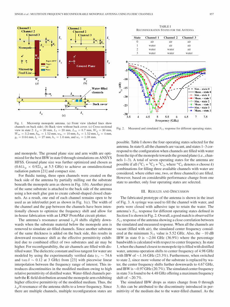
TABLE IRECONFIGURATION STATES FOR THE ANTENNA
Fig. 2. Measured and simulated S11 response for different operating states.
possible. Table I shows the four operating states selected for theantenna. In state 0, all the channels are vacant, and states 1–3 cor-respond to the configuration when channels are filled with waterfrom the tip of the monopole towards the ground plane (i.e., chan-nels 1–3). A total of seven operating states for the antenna arepossible if all (3C1 + 3C2 + 3C3, where nCk denotes n choose k)combinations for filling three available channels with water areconsidered, where either one, two, or three channel(s) are filled.However, based on considerable performance change from onestate to another, only four operating states are selected.
III. RESULTS AND DISCUSSION
The fabricated prototype of the antenna is shown in the insetof Fig. 3. A syringe was used to fill the channel with water, andports were closed with adhesive tape to retain the water. Theantenna’s S11 response for different operating states defined inSection I is shown in Fig. 2. Overall, a good match is observed forS11 response of the antenna showing a close correlation betweenthe simulated and measured response. When all the channels arevacant (filled with air), the simulated center frequency consid-ered at the minimum S11 value is 5.52 GHz. Also, the −10 dBIBW in state 0 is ∼2.04 GHz (36.9%) where the percentagebandwidth is calculated with respect to center frequency. In state1, when the channel closest to monopole tip is filled with distilledwater, antenna operation shifts to center frequency of 4.98 GHzwith IBW of ∼1.16 GHz (23.3%). Furthermore, when switchedto state 2, since more volume of the substrate is replaced by wa-ter, the center frequency shifts further downwards to 4.67 GHz,and IBW is∼0.97 GHz (20.7%). The simulated center frequencyin state 3 is found to be 4.48 GHz offering a maximum frequencyshift of ∼20.7%.
The simulated IBW drops as states change from 0 through3; this can be attributed to the discontinuity introduced in per-mittivity of the medium due to the water-filled channel. As the
858 IEEE ANTENNAS AND WIRELESS PROPAGATION LETTERS, VOL. 18, NO. 5, MAY 2019
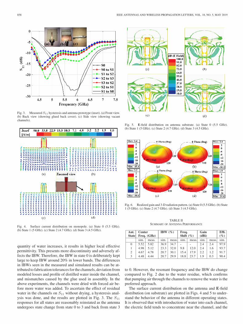
Fig. 3. Measured S11 hysteresis and antenna prototype (inset). (a) Front view.(b) Back view (showing glued back cover). (c) Side view (showing vacantchannels).
Fig. 4. Surface current distribution on monopole. (a) State 0 (5.5 GHz).(b) State 1 (5 GHz). (c) State 2 (4.7 GHz). (d) State 3 (4.5 GHz).
quantity of water increases, it results in higher local effectivepermittivity. This presents more discontinuity and adversely af-fects the IBW. Therefore, the IBW in state 0 is deliberately keptlarge to keep IBW around 20% in lower bands. The differencesin IBWs seen in the measured and simulated results can be at-tributed to fabrication tolerances for the channels, deviation frommodeled losses and profile of distilled water inside the channel,and mismatches caused by the glue used in assembly. In theabove experiments, the channels were dried with forced air be-fore more water was added. To ascertain the effect of residualwater in the channels on S11 without drying, a hysteresis anal-ysis was done, and the results are plotted in Fig. 3. The S11
responses for all states are reasonably reinstated as the antennaundergoes state change from state 0 to 3 and back from state 3
Fig. 5. E-field distribution on antenna substrate. (a) State 0 (5.5 GHz).(b) State 1 (5 GHz). (c) State 2 (4.7 GHz). (d) State 3 (4.5 GHz).
Fig. 6. Realized gain and 3-D radiation pattern. (a) State 0 (5.5 GHz). (b) State1 (5 GHz). (c) State 2 (4.7 GHz). (d) State 3 (4.5 GHz).
TABLE IISUMMARY OF ANTENNA PERFORMANCE
to 0. However, the resonant frequency and the IBW do changecompared to Fig. 2 due to the water residue, which confirmsthat pumping air through the channels to remove the water is thepreferred approach.
The surface current distribution on the antenna and E-fielddistribution (on substrate) are plotted in Figs. 4 and 5 to under-stand the behavior of the antenna in different operating states.It is observed that with introduction of water into each channel,the electric field tends to concentrate near the channel, and the
SINGH et al.: MULTISTATE FREQUENCY-RECONFIGURABLE MONOPOLE ANTENNA USING FLUIDIC CHANNELS 859
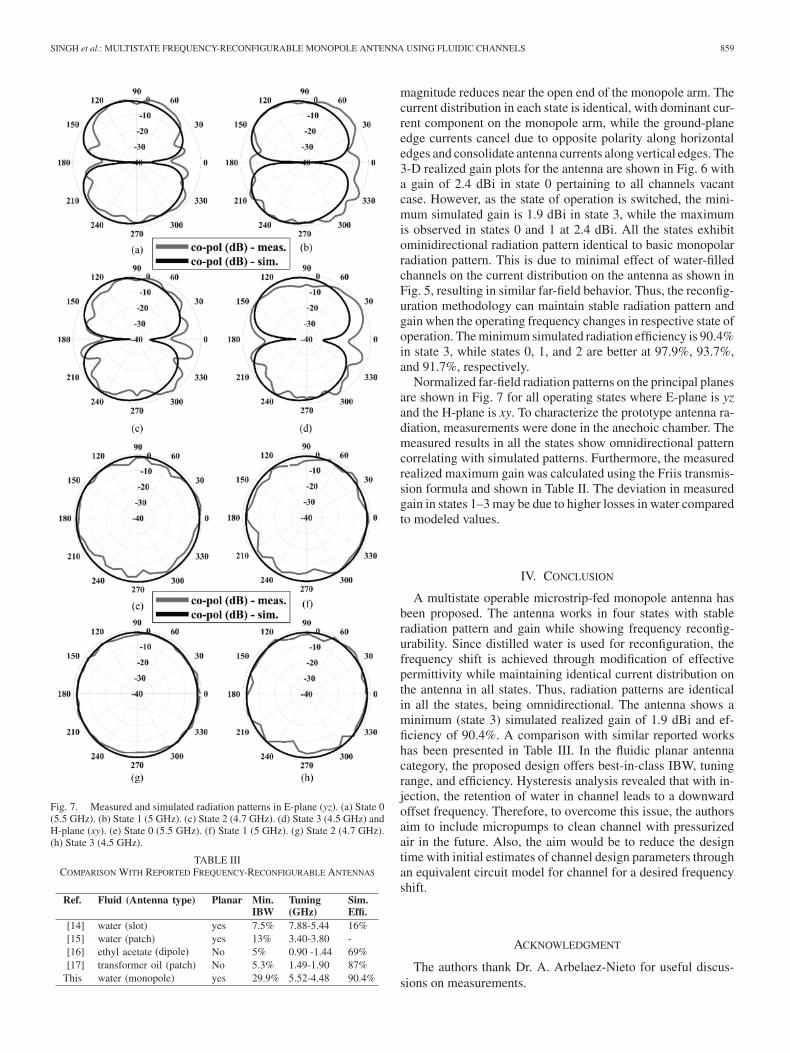
Fig. 7. Measured and simulated radiation patterns in E-plane (yz). (a) State 0(5.5 GHz). (b) State 1 (5 GHz). (c) State 2 (4.7 GHz). (d) State 3 (4.5 GHz) andH-plane (xy). (e) State 0 (5.5 GHz). (f) State 1 (5 GHz). (g) State 2 (4.7 GHz).(h) State 3 (4.5 GHz).
TABLE IIICOMPARISON WITH REPORTED FREQUENCY-RECONFIGURABLE ANTENNAS
magnitude reduces near the open end of the monopole arm. Thecurrent distribution in each state is identical, with dominant cur-rent component on the monopole arm, while the ground-planeedge currents cancel due to opposite polarity along horizontaledges and consolidate antenna currents along vertical edges. The3-D realized gain plots for the antenna are shown in Fig. 6 witha gain of 2.4 dBi in state 0 pertaining to all channels vacantcase. However, as the state of operation is switched, the mini-mum simulated gain is 1.9 dBi in state 3, while the maximumis observed in states 0 and 1 at 2.4 dBi. All the states exhibitominidirectional radiation pattern identical to basic monopolarradiation pattern. This is due to minimal effect of water-filledchannels on the current distribution on the antenna as shown inFig. 5, resulting in similar far-field behavior. Thus, the reconfig-uration methodology can maintain stable radiation pattern andgain when the operating frequency changes in respective state ofoperation. The minimum simulated radiation efficiency is 90.4%in state 3, while states 0, 1, and 2 are better at 97.9%, 93.7%,and 91.7%, respectively.
Normalized far-field radiation patterns on the principal planesare shown in Fig. 7 for all operating states where E-plane is yzand the H-plane is xy. To characterize the prototype antenna ra-diation, measurements were done in the anechoic chamber. Themeasured results in all the states show omnidirectional patterncorrelating with simulated patterns. Furthermore, the measuredrealized maximum gain was calculated using the Friis transmis-sion formula and shown in Table II. The deviation in measuredgain in states 1–3 may be due to higher losses in water comparedto modeled values.
IV. CONCLUSION
A multistate operable microstrip-fed monopole antenna hasbeen proposed. The antenna works in four states with stableradiation pattern and gain while showing frequency reconfig-urability. Since distilled water is used for reconfiguration, thefrequency shift is achieved through modification of effectivepermittivity while maintaining identical current distribution onthe antenna in all states. Thus, radiation patterns are identicalin all the states, being omnidirectional. The antenna shows aminimum (state 3) simulated realized gain of 1.9 dBi and ef-ficiency of 90.4%. A comparison with similar reported workshas been presented in Table III. In the fluidic planar antennacategory, the proposed design offers best-in-class IBW, tuningrange, and efficiency. Hysteresis analysis revealed that with in-jection, the retention of water in channel leads to a downwardoffset frequency. Therefore, to overcome this issue, the authorsaim to include micropumps to clean channel with pressurizedair in the future. Also, the aim would be to reduce the designtime with initial estimates of channel design parameters throughan equivalent circuit model for channel for a desired frequencyshift.
ACKNOWLEDGMENT
The authors thank Dr. A. Arbelaez-Nieto for useful discus-sions on measurements.
860 IEEE ANTENNAS AND WIRELESS PROPAGATION LETTERS, VOL. 18, NO. 5, MAY 2019
REFERENCES
[1] J. Costantine, Y. Tawk, S. E. Barbin, and C. G. Christodoulou, “Recon-figurable antennas: Design and applications,” Proc. IEEE, vol. 103, no. 3,pp. 424–437, Mar. 2015.
[2] Y. Tawk, J. Costantine, and C. G. Christodoulou, “Cognitive-radio andantenna functionalities: A tutorial [Wireless Corner],” IEEE AntennasPropag. Mag., vol. 56, no. 1, pp. 231–243, Feb. 2014.
[3] K. Entesari and A. P. Saghati, “Fluidics in microwave components,” IEEEMicrow. Mag., vol. 17, no. 6, pp. 50–75, Jun. 2016.
[4] M. Abdallah and C. E. Saavedra, “Fluidically-tuned reflection oscillatorat C-band,” in Proc. Int. Symp. Antenna Technol. Appl. Electromagn. (AN-TEM), Waterloo, ON, Canada, Aug. 2018, pp. 1–2.
[5] A. Dey, R. Guldiken, and G. Mumcu, “Wideband frequency tunable liquidmetal monopole antenna,” in Proc. IEEE Antennas Propag. Soc. Int. Symp.,Orlando, FL, USA, Jul. 2013, pp. 392–393.
[6] A. J. King, J. F. Patrick, N. R. Sottos, S. R. White, G. H. Huff, and J. T.Bernhard, “Microfluidically switched frequency-reconfigurable slot anten-nas,” IEEE Antennas Wireless Propag. Lett., vol. 12, pp. 828–831, 2013.
[7] S. Shah and S. Lim, “Microfluidically frequency-reconfigurable quasi-Yagi dipole antenna,” Sensors, vol. 18, no. 9, pii: E2935, 2018.
[8] A. H. Naqvi and S. Lim, “Microfluidically polarization-switchable meta-surfaced antenna,” IEEE Antennas Wireless Propag. Lett., vol. 17, no. 12,pp. 2255–2259, Dec. 2018.
[9] C. Wang, J. C. Yeo, H. Chu, C. T. Lim, and Y. Guo, “Design of a reconfig-urable patch antenna using the movement of liquid metal,” IEEE AntennasWireless Propag. Lett., vol. 17, no. 6, pp. 974–977, Jun. 2018.
[10] M. Wang, M. R. Khan, M. D. Dickey, and J. J. Adams, “A compound fre-quency and polarization-reconfigurable crossed dipole using multidirec-tional spreading of liquid metal,” IEEE Antennas Wireless Propag. Lett.,vol. 16, pp. 79–82, 2017.
[11] D. Rodrigo, L. Jofre, and B. A. Cetiner, “Circular beam-steering recon-figurable antenna with liquid metal parasitics,” IEEE Trans. AntennasPropag., vol. 60, no. 4, pp. 1796–1802, Apr. 2012.
[12] J. Lee and C.-J. Kim, “Surface-tension-driven microactuation based oncontinuous electrowetting,” J. Microelectromech. Syst., vol. 9, no. 2,pp. 171–180, Jun. 2000.
[13] Z. Wan, H. Zeng, and A. Feinerman, “Reversible electrowetting of liquid-metal droplet,” J. Fluids Eng., vol. 129, no. 4, pp. 388–394, 2006.
[14] C. Murray and R. R. Franklin, “Independently tunable annular slot antennaresonant frequencies using fluids,” IEEE Antennas Wireless Propag. Lett.,vol. 13, pp. 1449–1452, 2014.
[15] W. Su, B. Cook, M. Tentzeris, C. Mariotti, and L. Roselli, “A novelinkjet-printed microfluidic tunable coplanar patch antenna,” in Proc.IEEE Antennas Propag. Soc. Int. Symp. (APSURSI), Memphis, TN, USA,Jul. 2014, pp. 858–859.
[16] M. Konca and P. A. Warr, “A frequency-reconfigurable antenna architec-ture using dielectric fluids,” IEEE Trans. Antennas Propag., vol. 63, no. 12,pp. 5280–5286, Dec. 2015.
[17] S. Wang, L. Zhu, and W. Wu, “A novel frequency-reconfigurable patchantenna using low-loss transformer oil,” IEEE Trans. Antennas Propag.,vol. 65, no. 12, pp. 7316–7321, Dec. 2017.
[18] J. Liang, G. Huang, K. Qian, S. Zhang, and T. Yuan, “An azimuth-patternreconfigurable antenna based on water grating reflector,” IEEE Access,vol. 6, pp. 34804–34811, 2018.
[19] Y. Qian and Q. Chu, “A polarization-reconfigurable water-loaded mi-crostrip antenna,” IEEE Antennas Wireless Propag. Lett., vol. 16, pp. 2179–2182, 2017.
[20] A. Singh and C. Saavedra, “A frequency-reconfigurable water-loaded pla-nar monopole antenna,” in Proc. Int. Symp. Antenna Technol. Appl. Elec-tromagn. (ANTEM), Waterloo, ON, Canada, Aug. 2018, pp. 1–4.
[21] M. J. Ammann and M. John, “Optimum design of the printed stripmonopole,” IEEE Antennas Propag. Mag., vol. 47, no. 6, pp. 59–61, Dec.2005.
[22] D. M. Pozar, Microwave Engineering. Hoboken, NJ, USA: Wiley, 2009.[23] N. D. Pavlov and Y. A. Baloshin, “Electromagnetic properties of water
on ghz frequencies for medicine tasks and metamaterial applications,” J.Phys.: Conf. Ser., vol. 643, Art. no. 012047, 2015.