the haverford educational risc architectureww3.haverford.edu/computerscience/resources/... · the...
TRANSCRIPT

The Haverford Educational RISC Architecture
Table of contents
List of figures . . . . . . . . . . . . . . . . . . . . . . . . . . . . . . . . . . . . . . . . . . . . . . . . . . 2
1 Purpose and History . . . . . . . . . . . . . . . . . . . . . . . . . . . . . . . . . . . . . . . . . . . 3
2 Architecture Overview: Registers, Flags, Memory Size . . . . . . . . . . . . . . . . . . 3
3 Instruction Set . . . . . . . . . . . . . . . . . . . . . . . . . . . . . . . . . . . . . . . . . . . . . . . 4
3.1 Arithmetic, Shift, and Logical Instructions (b15=1, b15:12= 0011) . . . . . . . . . . . . . 43.1.1 SETLO and SETHI (b15:13=111) . . . . . . . . . . . . . . . . . . . . . . . . . . . . . . 43.1.2 Three-address operations (b15:13=110, 101, or 100) . . . . . . . . . . . . . . . . . . . 43.1.3 Shifts, increments, and flag operations (b15:12= 0011) . . . . . . . . . . . . . . . . . 5
Shifts . . . . . . . . . . . . . . . . . . . . . . . . . . . . . . . . . . . . . . . . . . . . . . . 5
Set/clear flags . . . . . . . . . . . . . . . . . . . . . . . . . . . . . . . . . . . . . . . . . . 5
Save/restore flags . . . . . . . . . . . . . . . . . . . . . . . . . . . . . . . . . . . . . . . . 6
Increments . . . . . . . . . . . . . . . . . . . . . . . . . . . . . . . . . . . . . . . . . . . . 6
3.2 Memory Instructions (b15:14= 01) . . . . . . . . . . . . . . . . . . . . . . . . . . . . . . . . . 63.3 Control-Flow and Other Instructions (b15:14= 00) . . . . . . . . . . . . . . . . . . . . . . . 7
3.3.1 Branches, including jumps (b15:13= 000) . . . . . . . . . . . . . . . . . . . . . . . . . . 73.3.2 Function call and return; Interrupt processing (b15:12= 0010) . . . . . . . . . . . . . 8
4 Assembly Language Conventions and Pseudo-Operations . . . . . . . . . . . . . . . . 9
5 Idioms . . . . . . . . . . . . . . . . . . . . . . . . . . . . . . . . . . . . . . . . . . . . . . . . . . . . . 10
5.1 Single-Precision Arithmetic . . . . . . . . . . . . . . . . . . . . . . . . . . . . . . . . . . . . . 105.2 Double-Precision or Mixed-Precision Arithmetic . . . . . . . . . . . . . . . . . . . . . . . . 105.3 Control Flow and Branch Instructions . . . . . . . . . . . . . . . . . . . . . . . . . . . . . . 115.4 Data Memory and Memory Instructions . . . . . . . . . . . . . . . . . . . . . . . . . . . . . 12
5.4.1 Arrays and Address Arithmetic . . . . . . . . . . . . . . . . . . . . . . . . . . . . . . . 125.4.2 Characters and Strings . . . . . . . . . . . . . . . . . . . . . . . . . . . . . . . . . . . . . 15
5.5 Function Calls . . . . . . . . . . . . . . . . . . . . . . . . . . . . . . . . . . . . . . . . . . . . . . 165.5.1 Function Calls with Parameters in Registers, “Caller-Save” of Registers . . . . . . 185.5.2 Function Call with Parameters on Stack, “Callee-Save” Registers . . . . . . . . . . 235.5.3 Other Options . . . . . . . . . . . . . . . . . . . . . . . . . . . . . . . . . . . . . . . . . . 28
Bibliography . . . . . . . . . . . . . . . . . . . . . . . . . . . . . . . . . . . . . . . . . . . . . . . . . . . 30
List of figures
Single-Precision Arithmetic. . . . . . . . . . . . . . . . . . . . . . . . . . . . . . . . . . . . . . . . . . . . . . 10Mixed-Precision Arithmetic. . . . . . . . . . . . . . . . . . . . . . . . . . . . . . . . . . . . . . . . . . . . . . 10Control Flow and HERA Branch Instructions. . . . . . . . . . . . . . . . . . . . . . . . . . . . . . . . . . . . 11Integer Variables Stored in Memory . . . . . . . . . . . . . . . . . . . . . . . . . . . . . . . . . . . . . . . . . 13Scanning Elements of an Array . . . . . . . . . . . . . . . . . . . . . . . . . . . . . . . . . . . . . . . . . . . 14Counting the Number of Question Marks in a Tiger-style String . . . . . . . . . . . . . . . . . . . . . . . . . 15Simple Function and Call, Showing HERA CALL and RETURN Instructions. . . . . . . . . . . . . . . . . . . . . 17Typical Stack Frame with Parameters and Return Value in Registers . . . . . . . . . . . . . . . . . . . . . . 18Simple Function of Figure 7 Revised to Use Stack Frames . . . . . . . . . . . . . . . . . . . . . . . . . . . . . 19Calling two_x_plus_y with Parameters in Registers . . . . . . . . . . . . . . . . . . . . . . . . . . . . . . . . 21Function two_x_plus_y . . . . . . . . . . . . . . . . . . . . . . . . . . . . . . . . . . . . . . . . . . . . . . . 21Main Program to Illustrate General Function Calls with Parameters in Registers . . . . . . . . . . . . . . . . 22Active Stack Frames During Execution of two_x_plus_y From Figure 12’s Main Program . . . . . . . . . . . 22Typical Stack Frame with Parameters and Return Value on Stack . . . . . . . . . . . . . . . . . . . . . . . . 23Example Function two_x_plus_y, Illustrating Stack Frame Maintenance and Usage . . . . . . . . . . . . . . . 24Typical Stack Frame with Parameters and Return Value on Stack, Just Before a CALL . . . . . . . . . . . . . 25Calling A Function, with Parameters on Stack . . . . . . . . . . . . . . . . . . . . . . . . . . . . . . . . . . . 26Main Program to Call the Function foo in Figure 17 or the Upcoming Figure 21. . . . . . . . . . . . . . . . . 27Stack Layout for Figures 17, 15, and 18 Just Before DEC(SP, 2) in two_x_plus_y. . . . . . . . . . . . . . . . 27Function two_a_plus_y, Illustrating the Use of the Static Link (see also Figure 21). . . . . . . . . . . . . . . 28Function Calls with Parameters on Stack and an Escaping Local Variable . . . . . . . . . . . . . . . . . . . . 29
The Haverford Educational RISC Architecture, Version 2.3.3 September 2014

1 Purpose and History
The Haverford Educational RISC Architecture (HERA) provides a foundation for a multi-courseproject unifying Haverford’s upper-level computer science curriculum. HERA is powerful enoughto introduce assembly language programming in Principles of Programming Languages and serveas a target for compilers in Compiler Design, yet be simple enough to be built as a studentproject in Principles of Computer Organization (using, for example, TKGate [Han04]) andextended in hardware/software co-design projects in Operating Systems. Thus, through thesefour classes, students produce a system in which high-level code is translated into machine lan-guage that can be executed on a microprocessor they have designed, and on which I/O to anASCII terminal can be performed through simple device drivers they have written themselves.This philosophy of building the simplest system that actually works is coupled with lectures con-trasting HERA with real-world systems. For more details on the educational uses of HERA, see[Won06].
The HERA-C development system allows students to execute HERA assembly language pro-grams before their own system is operational. HERA-C is a set of C macros that allows a stan-dard C or C++ development environment to compile, execute, and debug HERA programs. Thislets students start to use HERA with minimum distraction from new tools. See [Won03] for moreinformation about HERA-C and other supporting tools.
The HERA system originated with an attempt to simplify Andrew Appel’s “Jouette” [App98]for use in a Computer Hardware course based on [Man88]. The current system owes much to thehelpful criticism and patience of students who endured early versions. Todd Miller (HaverfordCollege class of 2001) also contributed significantly to the early macros that became HERA-C.My thanks to all of you!
2 Architecture Overview: Registers, Flags, Memory Size
The HERA processor sixteen 16-bit general purpose registers, known as R0R15, which can beused as operands for most instructions (e.g., ADD, or LOAD). Several of these also play special rolesin some instructions. The stack pointer (R15, also known as SP ) and frame pointer (R14, or FP )are also modified by the function call and return operations. The temporary register (R13, or Rt)is used during function calls, returns, and in multiplication operations, as well as by some of theassembly-language pseudo-operations given in Section 4. The zero register (R0) always has thevalue 0, providing a mechanism for performing operations such as comparison (the CMP pseudo-op) and negation (NEG).
The processor also has a 16-bit program counter (known as PC) and a set of status/controlflags. The flags are: sign (s, or F0), which is set to true by a negative result; zero (z, or F1),which is set to true by a zero result; overflow (v, or F2), which is set to true by an overflow froma 2’s complement arithmetic operation; and carry (c, or F3), which is set to true by an overflowfrom an unsigned operation. These flags may be used in a branch instruction, and the value ofthe carry flag may be used in subsequent arithmetic operations. There is an additional 5th flagF4 known as “carry-block”. When carry-block is set the carry is not used during arithmetic opera-tions, providing for faster, simpler code for single-precision operations, or during shift operations.The carry-block flag can be saved, restored, or explicitly modified, but is not affected by otheroperations.
HERA can address 216 16-bit words of memory, using the LOAD and STORE instructions. AHERA CPU typically uses separate memory systems, each with its own address and data buses,for instructions and data (as with the original “Harvard architecture”, see Page K-4 of [HP07]).
Architecture Overview: Registers, Flags, Memory Size 3
The Haverford Educational RISC Architecture, Version 2.3.3 September 2014

3 Instruction Set
The HERA instruction set is comprised entirely of single-word operations, each identified with abrief acronym in assembly language or a certain pattern of bits in machine language. In thedescriptions below, subscripts are used to identify specific bits, e.g. b15:12 refers to bits 15through 12 inclusive (the first four of the sixteen bits of the instruction). Except for the memoryoperations LOAD and STORE, HERA instructions use and change only registers and flags.
3.1 Arithmetic, Shift, and Logical Instructions (b15=1, b15:12= 0011)
The Arithmetic, Shift, and Logical Instructions use the current values of registers and flags, andsometimes some bits of the instruction itself, to produce new values for registers and flags.
3.1.1 SETLO and SETHI (b15:13=111)
SETLO and SETHI operate on a destination register number and an immediate 8-bit value.
b15:12 Mnemonic Meaning Notes1110 SETLO(d, v) Rd← v set Rd to signed quantity v
1111 SETHI(d, v) (Rd)15:8← v set high 8 bits of Rd
SETLO sets Rd to the sign-extended value v, while SETHI changes the high 8 bits of Rd to v. ASETLO/SETHI sequence can thus be used to establish any arbitrary 16-bit pattern in a register,while SETLO by itself provides small constants. SETLO and SETHI do not affect any flags.
The format for the binary instructions for SETLO and SETHI is
15 14 13 12 11 10 9 8 7 6 5 4 3 2 1 0
1 1 1 l/h d v
3.1.2 Three-address operations (b15:13=110, 101, or 100)
The three-address HERA operations are
b15:12 Mnemonic Meaning Notes1000 AND(d, a,b) Rd(i)←Ra(i)∧Rb(i) bit-wise logical and1001 OR(d, a,b) Rd(i)←Ra(i)∨Rb(i) bit-wise logical or
1010 ADD(d, a,b) Rd←Ra+Rb+ (c∧F4′) use carry unless blocked
1011 SUB(d, a,b) Rd←Ra−Rb− (c′∧F4′) use carry unless blocked
1100 MULT(d, a,b) Rd← (Ra ∗Rb)15:0, signed multiplicationRt← (Ra ∗Rb)31:16
1101 XOR(d, a,b) Rd←Ra⊕Rb bit-wise exclusive or
These operations all modify the zero flag (true if and only if the result of the operation waszero) and sign flag (true iff b15 of the result is true). Addition and subtraction modify the over-flow flag and carry flag. Unless the carry-block flag is true, addition and subtraction use thecarry flag as the incoming carry. If carry-block is true, addition and subtraction ignore the carryflag (carry-in is 0 for addition and 1 for subtraction).
The multiplication operation computes the product of Ra and Rb, treated as signed integerquantities. It places the low-order 16 bits in Rd and the high-order 16 bits in the temporary reg-ister Rt. MULT modifies the zero, sign, and overflow flags (zero and sign are based on all 32 bits ofthe result; the overflow flag is true if and only if simply sign extending the lower 16 bits wouldnot produce the full 32-bit result). The MULT instruction leaves the carry flag unchanged.
4 Section 3
The Haverford Educational RISC Architecture, Version 2.3.3 September 2014

These operations are all encoded by the operation followed by d, a and b.
15 14 13 12 11 10 9 8 7 6 5 4 3 2 1 0
1 o d a b
3.1.3 Shifts, increments, and flag operations (b15:12= 0011)
When b15:12= 0011, a shift, increment, or flag control operation is performed, based on b7:4.
Shifts The HERA shift operations are:
b15:12 b7:4 Mnemonic Meaning Notes
0011 0000 LSL(d, b) Rd← shl/rolc (Rb) Logical shift left, possibly with carry0011 0001 LSR(d, b) Rd← shr/rorc (Rb) Logical shift right, possibly with carry0011 0010 LSL8(d, b) Rd← shl8 (Rb) Logical shift left 8 bits0011 0011 LSR8(d, b) Rd← shr8 (Rb) Logical shift right 8 bits0011 0100 ASL(d, b) Rd← asl/aslc (Rb) Arithmetic shift left, possibly with carry0011 0101 ASR(d, b) Rd← asr (Rb) Arithmetic shift right
The shift operations modify flags as appropriate for the value produced. For one-bit shifts,carry becomes the bit shifted out; for ASL, the overflow flag receives the value it would have afterADD(d, b,b); otherwise the flag values are not changed by shift instructions.
LSL, LSR, and ASL shift in the value (c ∧ F4′). Thus, when carry-block is false, the logical shift
operations correspond to a rotate with carry. ASR ignores the incoming carry, always producing aresult that is half of the (signed) value. The eight-bit shift operations shift in zeros, regardless ofthe carry block flag.
15 14 13 12 11 10 9 8 7 6 5 4 3 2 1 0
0 0 1 1 d o b
Set/clear flags Flags (or sets of flags) can be explicitly set or cleared with SETF or CLRF.
b15:12 b11 b7:4 Mnemonic Meaning Notes0011 0 0110 SETF(v) F←F ∨ v Set flags for which v is true0011 1 0110 CLRF(v) F←F ∧ v ′ Clear flags for which v is true
The value of b11 controls whether flags are set (b11 = 0) or cleared (b11 = 1). The values in b8and b3:0 are combined to make a five-bit value that is used to control which flags are set orcleared. The SETF and CLRF instructions are typically treated as single-operand instructions byassemblers, rather than operations with separate operands for v4 and v3:0. In other words,SETF(0x15) produces the instruction 0x3165, which sets the carry block (F4, or 0x10) and over-flow (F2, or 0x04) and sign (F0, or 0x01) flags, while CLRF(0x0a) produces 0x386a, which clearsthe carry (F3, or 0x08) and zero (F1, or 0x02) flags.
15 14 13 12 11 10 9 8 7 6 5 4 3 2 1 0
0 0 1 1 s/c 0 0 v4 0 1 1 0 v3 v2 v1 v0
Instruction Set 5
The Haverford Educational RISC Architecture, Version 2.3.3 September 2014

Save/restore flags Flags can also be collectively saved to or loaded from a register.b15:12 b7:4 b3 Mnemonic Meaning Notes0011 0111 0 SAVEF(d) Rd←F Save flags to Rd
0011 0111 1 RSTRF(d) F←Rd Restore flags from Rd
The value of b3 controls whether flags are saved (b3 = 0) or restored (b3 = 1). Note that theflags are saved in bits 4:0 of Rd, not b8 and b3:0 as in the SETF and CLRF instructions.
15 14 13 12 11 10 9 8 7 6 5 4 3 2 1 0
0 0 1 1 d 0 1 1 1 s/r 0 0 0
Increments The increment and decrement operations are
b15:12 b7:6 Mnemonic Meaning Notes0011 10 INC(d, δ) Rd←Rd+ δ Increment Rd by δ
0011 11 DEC(d, δ) Rd←Rd− δ Decrement Rd by δ
The increment and decrement operations update the overflow and carry flags (as well as zeroand sign), but always ignore the incoming carry.
The value of b6 controls whether an increment (b6=0) or decrement (b6=1) is performed.
15 14 13 12 11 10 9 8 7 6 5 4 3 2 1 0
0 0 1 1 d 1 i/d ǫ
Note that the value added or subtracted from Rd is one more than the unsigned quantitygiven in bits 5:0 (labeled ǫ above) — there is no increment or decrement by zero. Note that, byconvention, assembly language translators require that the programmer express δ, the quantity tobe added or subtracted for INC and DEC. For example, INC(r1,6) produces the machine languageinstruction 0x3185, not 0x3186, to add the constant 6 to R1.
3.2 Memory Instructions (b15:14= 01)
The LOAD and STORE instructions move data between registers and memory.
b15:13 Mnemonic Meaning Notes
010 LOAD(d, o,b) Rd←M [Rb+ o] Load memory cell into Rd.011 STORE(d, o,b) M [Rb+ o]←Rd Store value of Rd into memory.
No flag is modified or used during a STORE instruction; LOAD modifies the s and z flags andleaves others unchanged. The binary format for these instructions is
15 14 13 12 11 10 9 8 7 6 5 4 3 2 1 0
0 1 l/s o4 d o3 o2 o1 o0 b
where s is 0 for a LOAD operation and 1 for a STORE, and data is transferred between Rd andmemory cell Rb + o (where o is a 5-bit unsigned number (0..31) constructed from b13 followed byb7:4). By convention, assemblers combine all o bits into a single offset parameter, e.g. LOAD(r1,
17,r2) loads M [R2+ 17] into R1.
6 Section 3
The Haverford Educational RISC Architecture, Version 2.3.3 September 2014

3.3 Control-Flow and Other Instructions (b15:14= 00)
Control-flow instructions include conditional branches, unconditional branches (“jump” instruc-tion), and function and interrupt instructions.
3.3.1 Branches, including jumps (b15:13= 000)
HERA provides the following branches that transfer to an address in a register (b) and relativebranches that transfer to the current positions plus an 8-bit signed offset (o). Relative branchesare distinguished in assembly language by an appended “R” in the operation name.
b15:12 b11:8 Mnemonic Meaning
0001/0 0000 BR(b)/BRR(o) Unconditional branch – true
0001/0 0001 (unused)0001/0 0010 BL(b)/BLR(o) Branch if signed result <0 — (s⊕ v)0001/0 0011 BGE(b)/BGER(o) Branch if signed result >0 — (s⊕ v)′
0001/0 0100 BLE(b)/BLER(o) Branch if signed result 60 — ((s⊕ v)∨ z)0001/0 0101 BG(b)/BGR(o) Branch if signed result >0 — ((s⊕ v)∨ z)′
0001/0 0110 BULE(b)/BULER(o) Branch if unsigned result 60 — (c′∨ z)0001/0 0111 BUG(b)/BUGR(o) Branch if unsigned result >0 — (c′∨ z)′
0001/0 1000 BZ(b)/BZR(o) Branch if zero — z (if CMP operands =)0001/0 1001 BNZ(b)/BNZR(o) Branch if not zero — z ′ (if operands �)0001/0 1010 BC(b)/BCR(o) Branch if carry — c (unsigned result >0)0001/0 1011 BNC(b)/BNCR(o) Branch if not carry — c′ (unsigned <0)0001/0 1100 BS(b)/BSR(o) Branch if sign (negative) — s
0001/0 1101 BNS(b)/BNSR(o) Branch if not sign (non-negative) — s′
0001/0 1110 BV(b)/BVR(o) Branch if overflow — v
0001/0 1111 BNV(b)/BNVR(o) Branch if not overflow — v ′
Branches, both conditional and unconditional, are indicated by b15:13 = 000. For both, b11:8indicate the condition c under which the branch is to be taken; see section 9-8 of M. MorrisMano’s “Computer Engineering: Hardware Design” for an explanation of which flags are used foreach branch.
The format for register-mode branch instructions is
15 14 13 12 11 10 9 8 7 6 5 4 3 2 1 0
0 0 0 1 c 0 0 0 0 b
where Rb gives the address for the next instruction to be executed if c is satisfied. The format forrelative branch instructions is
15 14 13 12 11 10 9 8 7 6 5 4 3 2 1 0
0 0 0 0 c o
where o is treated as an 8-bit signed quantity (-128...127) giving the offset from the branchinstruction itself (i.e., the address for the next instruction to be executed if c is satisfied is PC +o, where PC indicates the value of the program counter for the branch instruction itself). Thus,the unconditional relative branch instruction (b7:0 = 0) includes the special cases HALT (o=0) andNOP (o=1).
Instruction Set 7
The Haverford Educational RISC Architecture, Version 2.3.3 September 2014

3.3.2 Function call and return; Interrupt processing (b15:12= 0010)
HERA provides function call and return instructions as shown below.
b15:8 Mnemonic Comments
0010 0000 CALL(a,b) Call function at address Rb, with new stack frame starting at Ra
0010 0001 RETURN(a,b) Return, expecting return address and control link in Rb and Ra
In a CALL instruction, Rb gives the starting address of the function and Ra the location of thecalled function’s stack frame. The expectation is that each function’s stack frame will run frommemory cell FP to SP − 1 inclusive (see Section 5.5.2), and that at the time of the CALL instruc-tion, the Ra will point to the desired FP for the called function. The address of the startinginstruction of the function body is given in Rb. The function call instruction saves the address ofthe instruction following the CALL (i.e. the target of the RETURN instruction) into Rb and the pre-call value of FP into Ra. These values will be needed by the corresponding RETURN. Care mustbe taken to preserve these values and ensure consistent expectations about which registers areused; see Sections 5.5.2 and 5.5.1 for examples.
The semantics of a CALL instruction are
PC←Rb, Rb←PC +1, FP←Ra, Ra←FP .
The RETURN instruction reverses a CALL instruction, i.e.,
PC←Rb, FP←Ra, Ra←FP.
The function call instruction has the binary format
15 14 13 12 11 10 9 8 7 6 5 4 3 2 1 0
0 0 1 0 0 0 0 0 a b
and RETURN has the binary format
15 14 13 12 11 10 9 8 7 6 5 4 3 2 1 0
0 0 1 0 0 0 0 1 a b
The precise specification of interrupt and I/O processing (via hardware interrupt signals, thesoftware interrupt instruction SWI, and return from interrupt instruction RTI), is left as an exer-cise for students (as the lab projects in Haverford’s CMSC 356: Concurrency and Co-Design inOperating Systems). The following instructions are reserved for this purpose:
b Mnemonic Comments
0010 0010 0000 i SWI(i) Software interrupt #i
0010 0011 0000 0000 RTI() Return from interrupt
8 Section 3
The Haverford Educational RISC Architecture, Version 2.3.3 September 2014

4 Assembly Language Conventions and Pseudo-Operations
Operands for the operations listed in the previous section are listed in the order they appear inthe instruction (from b15 to b0). For example, AND(r1, r2,r3) sets R1 to R2 ∧ R3, andSTORE(r1, 5,r2) puts the contents of R1 into M [R2 + 5]. Note again that INC and DEC requirethe programmer to express the quantity to be added or subtracted, e.g., INC(r1,6) produces amachine-language instruction containing the operand 5 (i.e., 0xd185), which adds 6 to R1.
HERA assembly language typically defines the pseudo-operations and data statements listedbelow, for use in addition to the true operations provided by the processor and listed in the pre-vious section. Note that the HERA-C simulator requires that all data statements (i.e., INTEGER,DSKIP, TIGER_STRING, and DLABEL) precede all instructions. Also note that, in HERA-C and theHassem assembler, branches and calls must specify a label rather than an actual register or offset(Rt is used to hold the address in a CALL or register-mode branch).
Mnemonic Definition NotesSET(d, l) SETLO(d, l & 0xff); SETHI(d, l≫ 8) Rd← l (set Rd to 16-bit value l)MOVE(a,b) OR(a, b,R0) Ra←Rb
CMP(a, b) SETC( ); SUB(R0, a, b) Set flags for a− b
NEG(d, b) SETC( ); SUB(d, R0, b) Set Rd←−Rb
NOT(d, b) SET(Rt, 0xffff); XOR(d,Rt, b) Bit-wise complementSETC( ) SETF(0x08) Set the carry flagCLRC( ) CLRF(0x08) Clear the carry flagSETCB( ) SETF(0x10) Set the carry-block flagCLCCB( ) CLRF(0x18) Clear carry and carry-block flagsFLAGS(a) CLRC( ); ADD(R0, a, R0) Set flags for Ra
LABEL(L)/DLABEL(L) (no machine language generated) Define a label L⋆
INTEGER(i) i Put i in the current memory cellTIGER_STRING(s) s⋆⋆ Put string s in memory for TigerDSKIP(n) n uninitialized data memory cells Skip n cells of data memoryBR(L) SET(Rt, address(L)); BR(Rt) Do a branch to label L using Rt
BRR(L) BRR(address(L)) Do a relative branch to label LBG(L), BC(L)... ... Do any other branch using Rt
BGR(L), BCR(L)... ... Do any other relative branchNOP( ) BRR(1) Do nothing (“No operation”)HALT( ) BRR(0) Halt the programCALL(s, L) SET(Rt, address(L)); CALL(s, Rt) Do a call using Rt (i.e., R13)OPCODE(n) n⋆⋆⋆ Machine language op n
⋆ A label is a sequence of letters, numerals, and underscores starting with a letter (i.e., anyC++ identifier that does not start with an underscore). A label may be used in a CALL or branchinstruction, or (for a DLABEL) to identify the address of subsequent values given with INTEGER
and TIGER_STRING data statements. Due to a limitation in its implementation, HERA-C simu-lator requires the distinction between LABEL (for instructions) and DLABEL (for data).
⋆⋆ The string s cannot contain control characters (including newlines or tabs); some assem-blers may accept sequences starting with backslash as a C compiler would.
⋆⋆⋆ The OPCODE pseudo-operation is typically used to allow Hassem to assemble non-standardextensions of the HERA instruction set, e.g., for I/O instructions or for transactional memorysystems.
Assembly Language Conventions and Pseudo-Operations 9
The Haverford Educational RISC Architecture, Version 2.3.3 September 2014

5 Idioms
The following sections give typical usages of HERA operations, pseudo-operations, and datastatements.
5.1 Single-Precision Arithmetic
If a program employs only single-precision addition and subtraction, it typically begins by settingthe carry-block flag, and then uses the arithmetic operations it requires, as shown in Figure 1.The HERA machine language for this example is 3160 ... a123 a114 b543.
5.2 Double-Precision or Mixed-Precision Arithmetic
If a program employs double (or higher) precision arithmetic, i.e. uses two (or more) 16-bit regis-ters to represent a value of 32 (or more) bits, then the carry block must be disabled. Programsthat employ a mixture of single and higher precision may either turn carry-block on and off, orleave carry-block off and set the carry flag before single as well as double-precision operations.When carry-block is off, the carry flag should generally be cleared before beginning a sequence ofone or more addition operations, and set before beginning a subtraction sequence.
Figure 2 shows an example of double-precision addition followed by single-precision negation.The HERA machine language is 3968 ... 3868 a246 a135 3868 a228 a117 3068 b909.
// Set R1 to the single-precision sum of R2+R3+R4, R5 to R4-R3
SETCB() // Disable use of carry flag in single-precision
// ... (other instructions that may set the carry; we don’t care)
ADD(r1, r2,r3) // R1 = R2 + R3, * regardless of incoming carry *
ADD(r1, r1,r4) // R1 = R1 (i.e. R2+R3) + R4, * regardless of carry *
SUB(r5, r4,r3) // R5 = R4 - R3, * regardless of carry *
Figure 1. Single-Precision Arithmetic.
// Make [R1 R2] the (double-precision) sum of [R3 R4] and [R5 R6];
// then add [R7 R8] into [R1 R2];
// finally make R9 the (single precision) value -R9
CLCCB() // Enable use of carry flag for multiple-precision arithmetic
// ... (possibly other instructions that may set or clear the carry)
CLRC() // Start with carry-in=0 for least-significant digit
ADD(r2, r4,r6) // R2 = R4+R6, carry set if necessary
ADD(r1, r3,r5) // R1 = R3+R5 plus carry, if set by R4+R6
CLRC() // Start with carry-in=0 for least-significant digit of [R7 R8]
ADD(r2, r2,r8) // R2 = R2+R8 (i.e. R4+R6+R8), carry set if necessary
ADD(r1, r1,r7) // R1 = R1+R7, i.e. the most significant digit of the sum
SETC() // Make sure carry-in=1 for subtraction
SUB(r9, r0,r9) // Set R9=-R9 (as in the pseudo-op NEG(r9))
Figure 2. Mixed-Precision Arithmetic.
10 Section 5
The Haverford Educational RISC Architecture, Version 2.3.3 September 2014
5.3 Control Flow and Branch Instructions
Control flow normally proceeds through consecutive instructions, moving from address a toaddress a + 1 of the instruction memory. Branches (and CALL and RETURN — see Sections 5.5.2–5.5.3) provide a mechanism for moving to a different address, much as keywords like if andwhile provide a variation on the usual line-by-line sequence in a higher-level imperative language.
After executing a register-mode branch BR(Rb), a HERA processor will next execute whateverinstruction is in the instruction memory cell specified by Rb. So, for example, after the sequenceSET(Rt, 0x0174) BR(Rt) (or, equivalently, ed01 fd74 100d in machine language), the processorwill execute whatever instruction is in instruction memory cells 0x0174, then 0x0175, then0x0176, etc., unless 0x0174 or 0x0175 contains a branch, call, or return instruction.
After executing a relative-mode branches BRR(o) in instruction address a, a HERA processorwill next execute the instruction in address a+ o. Thus, either a BRR(4) (0004) in address 0x170or a BRR(-4) (00fc) in address 0x0178 would cause the the processor to proceed to the instruc-tion in address 0x0174. Note that BRR(0) (0000) prevents the processor from moving on to thenext instruction, and BRR(1) (0001) does nothing but go on to the next instruction.
Branch targets are defined in assembly language with labels defined with the LABEL keyword.Note that assemblers generally translate register-mode branch instructions as a SET(Rt, ...)/BR
sequence, so it is not safe to rely on the value in the temporary register (R13, also known as Rt)after a branch instruction. The HERA-C simulator overwrites Rt as part of each register-modebranch instructions to discourage the habit of relying on Rt inappropriately.
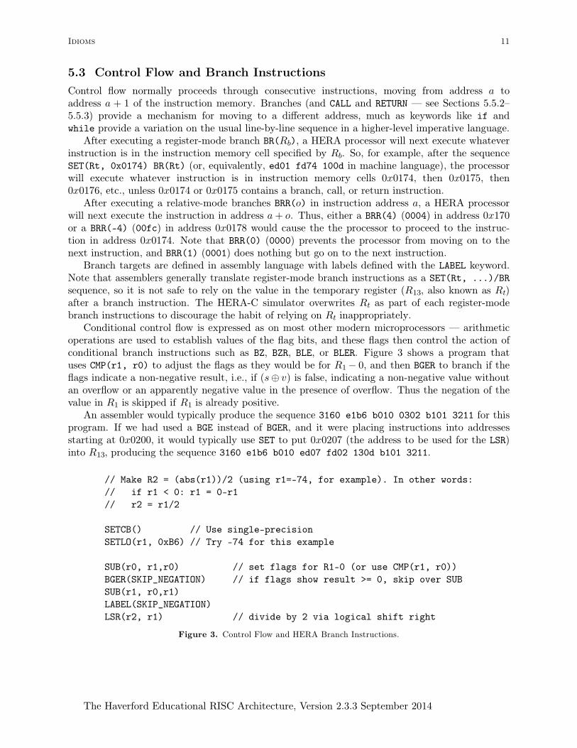
Conditional control flow is expressed as on most other modern microprocessors — arithmeticoperations are used to establish values of the flag bits, and these flags then control the action ofconditional branch instructions such as BZ, BZR, BLE, or BLER. Figure 3 shows a program thatuses CMP(r1, r0) to adjust the flags as they would be for R1− 0, and then BGER to branch if theflags indicate a non-negative result, i.e., if (s⊕ v) is false, indicating a non-negative value withoutan overflow or an apparently negative value in the presence of overflow. Thus the negation of thevalue in R1 is skipped if R1 is already positive.
An assembler would typically produce the sequence 3160 e1b6 b010 0302 b101 3211 for thisprogram. If we had used a BGE instead of BGER, and it were placing instructions into addressesstarting at 0x0200, it would typically use SET to put 0x0207 (the address to be used for the LSR)into R13, producing the sequence 3160 e1b6 b010 ed07 fd02 130d b101 3211.
// Make R2 = (abs(r1))/2 (using r1=-74, for example). In other words:
// if r1 < 0: r1 = 0-r1
// r2 = r1/2
SETCB() // Use single-precision
SETLO(r1, 0xB6) // Try -74 for this example
SUB(r0, r1,r0) // set flags for R1-0 (or use CMP(r1, r0))
BGER(SKIP_NEGATION) // if flags show result >= 0, skip over SUB
SUB(r1, r0,r1)
LABEL(SKIP_NEGATION)
LSR(r2, r1) // divide by 2 via logical shift right
Figure 3. Control Flow and HERA Branch Instructions.
Idioms 11
The Haverford Educational RISC Architecture, Version 2.3.3 September 2014
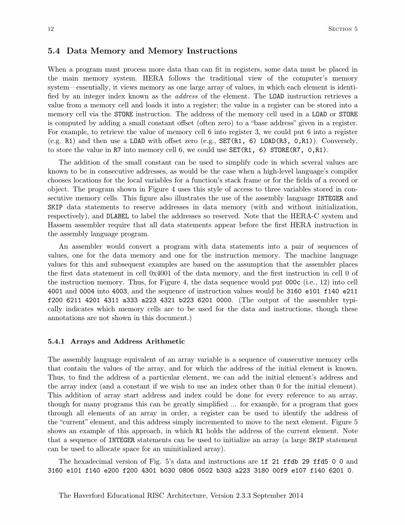
5.4 Data Memory and Memory Instructions
When a program must process more data than can fit in registers, some data must be placed inthe main memory system. HERA follows the traditional view of the computer’s memorysystem—essentially, it views memory as one large array of values, in which each element is identi-fied by an integer index known as the address of the element. The LOAD instruction retrieves avalue from a memory cell and loads it into a register; the value in a register can be stored into amemory cell via the STORE instruction. The address of the memory cell used in a LOAD or STOREis computed by adding a small constant offset (often zero) to a “base address” given in a register.For example, to retrieve the value of memory cell 6 into register 3, we could put 6 into a register(e.g. R1) and then use a LOAD with offset zero (e.g., SET(R1, 6) LOAD(R3, 0,R1)). Conversely,to store the value in R7 into memory cell 6, we could use SET(R1, 6) STORE(R7, 0,R1).
The addition of the small constant can be used to simplify code in which several values areknown to be in consecutive addresses, as would be the case when a high-level language’s compilerchooses locations for the local variables for a function’s stack frame or for the fields of a record orobject. The program shown in Figure 4 uses this style of access to three variables stored in con-secutive memory cells. This figure also illustrates the use of the assembly language INTEGER andSKIP data statements to reserve addresses in data memory (with and without initialization,respectively), and DLABEL to label the addresses so reserved. Note that the HERA-C system andHassem assembler require that all data statements appear before the first HERA instruction inthe assembly language program.
An assembler would convert a program with data statements into a pair of sequences ofvalues, one for the data memory and one for the instruction memory. The machine languagevalues for this and subsequent examples are based on the assumption that the assembler placesthe first data statement in cell 0x4001 of the data memory, and the first instruction in cell 0 ofthe instruction memory. Thus, for Figure 4, the data sequence would put 000c (i.e., 12) into cell4001 and 0004 into 4003, and the sequence of instruction values would be 3160 e101 f140 e211
f200 6211 4201 4311 a333 a223 4321 b223 6201 0000. (The output of the assembler typi-cally indicates which memory cells are to be used for the data and instructions, though theseannotations are not shown in this document.)
5.4.1 Arrays and Address Arithmetic
The assembly language equivalent of an array variable is a sequence of consecutive memory cellsthat contain the values of the array, and for which the address of the initial element is known.Thus, to find the address of a particular element, we can add the initial element’s address andthe array index (and a constant if we wish to use an index other than 0 for the initial element).This addition of array start address and index could be done for every reference to an array,though for many programs this can be greatly simplified ... for example, for a program that goesthrough all elements of an array in order, a register can be used to identify the address ofthe “current” element, and this address simply incremented to move to the next element. Figure 5shows an example of this approach, in which R1 holds the address of the current element. Notethat a sequence of INTEGER statements can be used to initialize an array (a large SKIP statementcan be used to allocate space for an uninitialized array).
The hexadecimal version of Fig. 5’s data and instructions are 1f 21 ffdb 29 ffd5 0 0 and3160 e101 f140 e200 f200 4301 b030 0806 0502 b303 a223 3180 00f9 e107 f140 6201 0.
12 Section 5
The Haverford Educational RISC Architecture, Version 2.3.3 September 2014

// Given (single-precision) integer variables X, Y, and Z,
// set Y to 17, then compute X+2Y-Z, and save as the result in X,
// e.g. execute "Y := 17; X := X+2Y-Z".
// Here, we assume that there is one data label "Variables",
// for consecutive memory cells for X, Y, and Z,
// with X is at offset 0 from that address, Y at offset 1, and Z at 2.
DLABEL(Variables)
INTEGER(12) // Initial value of X
SKIP(1) // Uninitialized space for 1 variable (Y)
INTEGER(4) // Initial value of Z
// And now, the program ... first, select single-precision
SETCB()
// Use R1 to identify where the variables start in memory:
SET(R1, Variables)
// Y := 17
SET(R2, 17)
STORE(R2, 1,R1) // Store in Y, i.e., 1 past "Variables"
// X := X+2Y-Z
LOAD(R2, 0,R1) // X (0 past "Variables") into R2
LOAD(R3, 1,R1) // Y into R3
ADD(R3, R3,R3) // R3 := R3+R3, i.e. 2Y
ADD(R2, R2,R3) // R2 is now X+2Y
LOAD(R3, 2,R1) // Z into R3
SUB(R2, R2,R3) // R2 is now X+2Y-Z
STORE(R2, 0,R1) // Store new value of X
HALT()
Figure 4. Integer Variables Stored in Memory
Idioms 13
The Haverford Educational RISC Architecture, Version 2.3.3 September 2014

// Compute the sum of the absoulute values of the elements in an array A,
// up to the first 0 value in A (there must be at least one).
// (single-precision)
//
// Note that, since we rely on finding a value of 0 in the array,
// rather than waiting for the array index to reach the maximum,
// we can just use a single register (R1) to record the address
// of the "current" element, and keep incrementing this address
// until we find that value of zero.
// If this program were to be used on an array that didn’t actually
// contain a 0 anywhere, the value of B would be unreliable, and
// if no memory cell anywhere contained a 0 it would run forever.
DLABEL(where_A_starts)
INTEGER(31) // initial element of A
INTEGER(33) // next element of A
INTEGER(-37)
INTEGER(41)
INTEGER(-43)
INTEGER(0)
DLABEL(where_B_is)
INTEGER(0) // initial value of B, to be changed
SETCB()
SET(R1, where_A_starts)
SET(R2, 0)
LABEL(top_of_loop)
LOAD(R3, 0,R1)
SUB(R0, R3,R0) // Set flags for R3-0
BZR(done_with_sum)
BGR(no_need_to_negate)
SUB(R3, R0,R3)
LABEL(no_need_to_negate)
ADD(R2, R2,R3)
INC(R1, 1)
BRR(top_of_loop)
LABEL(done_with_sum)
SET(R1, where_B_is)
STORE(R2, 0,R1)
HALT()
Figure 5. Scanning Elements of an Array
14 Section 5
The Haverford Educational RISC Architecture, Version 2.3.3 September 2014

5.4.2 Characters and Strings
HERA-C and Hassem convert single-quoted characters (e.g., ’?’) to numeric values, allowing atleast the ASCII subset of the Unicode system[Uni12], e.g., turning ’?’ into 63 (3F hexadecimal),so the assembly language SETLO(R5, ’?’) would be translated into e53f. They also allow C-lan-guage style escape characters, such as ’\n’ for a newline character.
Strings of characters can be represented in a number of ways, including sequences of non-nullcharacters terminated by a null character (character 0), as in most C/C++ libraries; a lengthfield followed by that many characters in the subsequent memory cells, as in Pascal and inAndrew Appel’s “Tiger” language; and others.
HERA-C and Hassem provide the TIGER_STRING data statement, which produces a string ofcharacters preceded by a character count (as in Tiger). Note that these strings still follow C-lan-guage conventions for escape characters. Figure 6 shows an example string processing program.The machine language for Figure 6’s instructions would be 3160 e100 f100 e201 f240 4302
3280 4402 e53f f500 b045 0902 3180 3280 33c0 09f8 e233 f240 6102 0, and the data seg-ment begins 31 49 73 20 74 68 69 73 20 61 6e 20 65 78 61 6d 70 6c 65 3f 20 57 69 ...
Hereafter, translation into machine language is left to any reader(s) interested in doing so.
// Count the number of times "?" appears in a String (single precision),
// and save the result in the memory cell labelled N_questions.
// The example uses a constant string created with TIGER_STRING,
// though the algorithm could be used for any string of this form.
DLABEL(The_string)
TIGER_STRING("Is this an example? With three questions? Really?")
DLABEL(N_questions)
INTEGER(0)
SETCB()
SET(R1, 0) // R1 will be the number of ’?’ found, initially 0
SET(R2, The_string) // R2 is now the address in memory of the string
LOAD(R3, 0,R2) // R3 = initial memory cell of a string (the length)
INC(R2, 1) // R2 = address of initial char. (’I’, in this example)
LABEL(top_of_loop)
LOAD(R4, 0,R2) // R4 is now the character itself
SET(R5, 63) // R5 is the character ’?’
SUB(R0, R4,R5) // Set flags for the character (i.e., R4) - ’?’
BNZR(not_a_question) // Skip the counting if R4-’?’ is not zero
INC(R1, 1) // Count one question
LABEL(not_a_question)
INC(R2, 1) // Move R2 to indicate the next character
DEC(R3, 1) // Decrease the count of how many remain
BNZR(top_of_loop) // If something other than 0 remain, keep going
SET(R2, N_questions)
STORE(R1, 0,R2) // Store the result in memory
HALT()
Figure 6. Counting the Number of Question Marks in a Tiger-style String
Idioms 15
The Haverford Educational RISC Architecture, Version 2.3.3 September 2014

5.5 Function Calls
In a high-level language, a programmer can avoid repeating a group of program steps by col-lecting them into a function (also known as a procedure or method, in some languages) and thencalling that function in several places. We could attempt to achieve a similar effect in assemblylanguage by labeling the to-be-repeated sequence of instructions and then branching to thissequence from several places. However, this would create a problem: at the end of the sequence,how could the “function” return to the point from which it had been called? To address thisproblem, most microprocessors provide specialized instructions to support function call andreturn, with CALL automatically saving information about the point from which the call is made,and RETURN restoring the information saved in the call. The HERA CALL and RETURN instructionsare as illustrated in Figure 7.
The HERA CALL and RETURN instructions employ a pair of registers to simultaneously updatetwo pieces of information about the running program. The second parameter to CALL andRETURN, traditionally Rt, is used to update the program counter in a way that resolves the “howto return to the point from which the function was called” problem mentioned above. The firstparameter, traditionally R12, will be discussed in Section 5.5.1. An assembly language call with alabel, such as Figure 7’s CALL(R12, two_r1_plus_r2), is translated by the assembler into a two-instruction sequence such as SET(Rt, two_r1_plus_r2) CALL(R12, Rt).
When the HERA CALL instruction is executed, the program branches to the address in thesecond register, in this case that of two_r1_plus_r2, and also saves in Rt the address of theinstruction after the CALL. This address, known as the return address, indicates the instructionthat should be executed after the function is finished. Having branched to the start oftwo_r1_plus_r2, the program then executes instructions in the usual way until it reaches theRETURN(R12, Rt), which causes it to branch back to the address given in Rt, i.e. the returnaddress saved by the call. Note that, since the two occurrences of CALL(R12, two_r1_plus_r2)
in Figure 7 are at different points in the program, the two calls will put different values into Rt,and thus each RETURN(R12, Rt) will continue the main program from the appropriate point.
Since it makes little sense to return from a function that has not been called, programs usu-ally take steps to ensure that only a call instruction will reach the start of the function. Figure 7accomplishes this with the branch to the label skip_over_two_r1_plus_r2.
The style of use of call and return in Figure 7 will work for simple programs, but note that itrequires a significant amount of “bookkeeping” work on the part of the programmer — the mainprogram can use r3 and r4 to hold the values of “a” and “b” only because the functiontwo_r1_plus_r2 won’t change either r3 or r4. In a larger program, this sort of bookkeepingquickly becomes unmanageable: the programmer(s) will have to remember the conventions ofmany different functions; the total number of registers needed may exceed the number providedby the microprocessor; and if a function is changed to use a different register, other functionsthat call it may no longer work. It is also difficult to create recursive functions using thisapproach.
These problems can all be addressed by adopting a standard convention by which all func-tions in a given program move some values from registers into memory. A variety of conventionshave been explored by machine language programmers and compiler writers; a good book oncompiler design will explain one or more of them in detail, e.g. see [App98]. The remainder ofSection 5.5 discusses the implementation of some possible function call conventions on the HERAsystem. Note that these are simply variations in the use of the instructions we have seen — theydo not involve changes to the definitions of the instructions themselves.
16 Section 5
The Haverford Educational RISC Architecture, Version 2.3.3 September 2014

// This program needs to compute 2*a+b and 2*(a+36)+(b-72)
// and will call two_r1_plus_r2 to do each of these
// a will be in r3 and b in r4, since r1 & r2 are used by the function
SETCB()
SET(r3, 17) // a = 17, for our example
SET(r4, 8) // b = 8, for our example
// now call the function two_r1_plus_r2(a, b)
MOVE(r1, r3) // first parameter is a
MOVE(r2, r4) // second parameter is b
CALL(R12, two_r1_plus_r2)
// ... work with result (in r1, according to the function)
// now for 2*(a+36)+(b-72)
SET(r5, 36)
ADD(r1, r3,r5) // first parameter is a+36
SET(r5, -72)
ADD(r2, r4,r5) // first parameter is b-72
CALL(R12, two_r1_plus_r2)
// ... work with result (in r1)
// don’t execute function unless we do so via a CALL,
// or else the RETURN will not make sense:
BR(skip_over_two_r1_plus_r2)
// The body of two_r1_plus_r2:
// compute 2*r1 + r2, leaving the result in r1
LABEL(two_r1_plus_r2)
ADD(r1, r1,r1) // 2*r1
ADD(r1, r1,r2) // 2*r1+r2
RETURN(R12, Rt)
LABEL(skip_over_two_r1_plus_r2)
Figure 7. Simple Function and Call, Showing HERA CALL and RETURN Instructions.
Idioms 17
The Haverford Educational RISC Architecture, Version 2.3.3 September 2014

(↑Higher addresses)�SP Next free memory, to be used if current function makes a call
last memory cell reserved for current function call... ...
more memory reserved for current function call� FP memory reserved for current function call
(↓Lower addresses) space used by function that called the current function
Figure 8. Typical Stack Frame with Parameters and Return Value in Registers
5.5.1 Function Calls with Parameters in Registers, “Caller-Save” of Registers
The most easily understood fix for the problems outlined above is to simply save, before eachCALL instruction, any register values that may be needed after the call. This frees us from havingto know which registers are used by the called function. It also lets us standardize every functionto communicate parameters and returned values in the same way, e.g. with R1 as the firstparameter, R2 as the second parameter, etc., and R1 also used for the return value.
To ensure that different functions don’t try to use the same memory locations for their savedregisters, and to allow recursive functions, we use a pair of registers to identify regions of memoryas a series of “stack frames”. These regions are allocated and freed in a strict last-in, first-outorder, i.e., as a “stack” data structure. (This corresponds to the usual pattern of entry into, andexit from, functions.) Each frame will contain memory cells to be used for one function call. Atany given time, the frame of the currently executing function will be identified by registers R14
and R15, known as the frame pointer (FP ) and stack pointer (SP ) respectively. All memory cellsfrom the address given in FP to one below that given in SP are considered part of the currentframe (so if FP =SP , the frame has size zero); memory elements below FP are typically in usefor the stack frame of the function that called the one that is currently executing; those at andabove SP are available for new frames if the current function makes a call. Figure 8 gives avisual representation of this layout (note that this diagram illustrates the conventions used forHERA; for some systems, the stack may grow from high addresses toward low addresses).
Figure 9 shows a revised version of Figure 7 in which this convention is used in its simplestform. The function two_r1_plus_r2 has been revised to overwrite r3 and r4, to illustrate thatthis no longer causes a problem for our main function (there is no other benefit to this change).Note the updates to the stack pointer, and load and store operations, to preserve values in thestack. In future examples, we will no longer include register names in each function name, since itis implicit that the parameters will be passed in registers r1, r2, etc., and that any other registersmay be overwritten in the function.
Note that Figure 9 includes significant unnecessary work: it is not actually necessary to decre-ment SP after the first call and then re-increment it before the second ... we could just have leftit at FP + 2. Furthermore, unless the “work with result” comments are replaced with operationsthat actually use (and change) r3 and r4, there is no need to load them back from the stackframe after the first call (and re-store them before the second). Thus, a more subtle approachthat avoids wasted instructions could be summarized “for any sequence of operations that willmake function calls, increment SP at the start of the sequence to make a stack frame that’s largeenough to hold all values that must be stored in the frame at any point; before each call, storeany registers whose values have changed but will be needed after the call; then, after the call, re-load only those that are actually needed; at the end of the sequence, decrement SP .”
18 Section 5
The Haverford Educational RISC Architecture, Version 2.3.3 September 2014

// Compute 2*a+b and 2*(a+36)+(b-72) by calling two_r1_plus_r2
// "a" will be in r3 and "b" in r4, since r1 & r2 are used for parameters
SETCB()
MOVE(SP, FP) // start main program with an empty stack frame
SET(r3, 17) // a = 17, for our example
SET(r4, 8) // b = 8, for our example
// call the function two_r1_plus_r2(a, b) --- first, set parameters
MOVE(r1, r3) // first parameter is a
MOVE(r2, r4) // second parameter is b
// allocate stack frame of size 2, save important registers there
INC(SP, 2) // SP is now 2 above FP; we can use FP+0 and FP+1
STORE(r3, 0,FP) // save r3 in stack frame
STORE(r4, 1,FP) // save r4 in stack frame
MOVE(R12, SP) // Use this SP as the FP for the called function
CALL(R12, two_r1_plus_r2) // actually call the function
// then restore things from the stack
LOAD(r3, 0,FP) // get r3 from stack frame
LOAD(r4, 1,FP) // get r4 from stack frame
DEC(SP, 2) // put SP back the way it was
// ... work with the result (in r1, according to our convention)
// now for 2*(a+36)+(b-72)
SET(r5, 36)
ADD(r1, r3,r5) // first parameter is a+36
SET(r5, -72)
ADD(r2, r4,r5) // first parameter is b-72
INC(SP, 2) // Save registers again
STORE(r3, 0,FP)
STORE(r4, 1,FP)
MOVE(R12, SP) // Use this SP as the FP for the called function
CALL(R12, two_r1_plus_r2)
LOAD(r3, 0,FP) // restore from stack frame again
LOAD(r4, 1,FP)
DEC(SP, 2)
// ... work with the result (in r1)
BR(skip_over_two_r1_plus_r2) // skip over function body
LABEL(two_r1_plus_r2) // compute 2*r1 + r2, leaving the result in r1
ADD(r3, r1,r1) // r3 = 2*r1
ADD(r4, r3,r2) // r4 = r3+r2 = 2*r1+r2
MOVE(r1, r4) // move return value from r4 into r1
RETURN(R12, Rt)
LABEL(skip_over_two_r1_plus_r2)
Figure 9. Simple Function of Figure 7 Revised to Use Stack Frames
Idioms 19
The Haverford Educational RISC Architecture, Version 2.3.3 September 2014

When functions call upon other functions, each nested function call must receive a differentstack frame. To make this work, the HERA CALL instruction must be given not only the addressof the function to be called, but also the frame pointer to be used in the called function (in thisconvention, always the current function’s SP ). In addition to adjusting the program counter andsaving the return address, CALL(R12, Rt) also sets FP to the value in R12 and saves the old FP
in R12. The old value of the frame pointer is used to re-establishing the stack frame when R12
and FP are once again switched by the RETURN(R12, Rt); the old frame pointer value is calledthe control link (abbreviated C.L.).
For the RETURN instruction to function properly, the values for the return address and controllink must not be destroyed during the execution of the function. Thus, the two_r1_plus_r2
example functions of Figures 7 and 9 rely on the fact that Rt and R12 have not been changed. Ina function that changes Rt (e.g., by using MULT, an assembler-generated branch instruction, or aCALL), the value of Rt must be preserved and then restored before the return. In the case of aCALL, the values of Rt and the control link (e.g., R12) should be preserved in the stack framerather than registers (since the latter will be over-written).
Putting together the aforementioned approaches to eliminating redundant steps and savingreturn addresses and control links, we adopt a convention in which we always call a function withthe following steps:
• Save (into the stack frame) any registers we may need after the call and whose values havenot yet been saved
• Put the parameter values into register R1, R2, ...
• Copy the current stack pointer into R12
• Use the CALL instruction CALL(R12, Rt), or assembly language CALL(R12, label)
• After the call, the returned value can be retrieved from R1
• Load (from the stack frame) any of the saved registers that we need before the next call.
To define a function to be called with these conventions, we:
• If necessary, increment SP to make space for saving registers at any point in the function
• If necessary, save the return address (from Rt) and the control link (from R12)
• Give the function body (in which parameters are assumed to be in R1, R2, ...)
• Put the function’s return value into R1
• If necessary, load Rt and the control link register (R12) from the stack frame
• If necessary, decrement SP to restore its value prior to the function
• Issue the RETURN instruction
This set of conventions is known as the “registers in parameters, caller-save” approach: we placefunction parameters in registers (rather than in memory), and have the calling function (ratherthan the called function) save any registers that may be overwritten. The ability to make recur-sive function calls follows naturally from careful adherence to the steps given above, or to theconventions of the next section.
20 Section 5
The Haverford Educational RISC Architecture, Version 2.3.3 September 2014

Figure 10 shows the use of these conventions to define a function foo, which then calls upontwo_x_plus_y of Figure 11 (this is just the original two_r1_plus_r2 function renamed). Asample main program to call upon foo is shown in Figure 12; Figure 13 shows the memory layout
// Translation of foo, assuming parameters in registers etc.
// int foo(a : int, b : int) : int = two_x_plus_y(a+b, b-a+75) * a
LABEL(foo)
// FIRST, make space to save R.A., old FP, and "a", then save them
INC(SP, 3)
STORE(Rt, 0,FP) // Save R.A.
STORE(R12,1,FP) // Save old F.P. ("control link")
STORE(r1, 2,FP) // Save "a" in current frame (only re-save if changed)
// copy "a" and "b" out of r1 and r2 so that we can use r1 and r2 in next call:
MOVE(r10, r1)
MOVE(r11, r2)
// set up parameters for call to two_x_plus_y
ADD(r1, r10,r11) // r1 = a+b
SUB(r2, r11,r10) // r2 = b-a
SETLO(r9, 75)
ADD(r2, r2,r9) // r2 = b-a+75
// actually make the call, with two_x_plus_y’s parameters in r1 and r2
MOVE(R12, SP) // initial stack frame for called function has size 0
CALL(R12,two_x_plus_y)
// Now restore "a" and multiply result of call (now in r1) by it:
LOAD(r2, 2,FP)
MULT(r1, r1,r2)
// Finally, restore R.A. and old F.P., do the return (result is already in r1)
LOAD(Rt, 0,FP)
LOAD(R12,1,FP)
DEC(SP, 3)
RETURN(R12, Rt)
Figure 10. Calling two_x_plus_y with Parameters in Registers
// Translation of a high-level-language function two_x_plus_y:
// int two_x_plus_y(x : int, y : int) : int = x+x+y
// assuming parameters/return in registers, no static link, caller-save of reg.,
// (as before single precision, assuming CB set)
LABEL(two_x_plus_y)
// Don’t bother saving Rt since it won’t be changed
// (no multiply, assembler-generated register mode branches, etc)
ADD(r1, r1,r1) // result = 2*x
ADD(r1, r1,r2) // result = 2*x+y
RETURN(R12, Rt)
Figure 11. Function two_x_plus_y
Idioms 21
The Haverford Educational RISC Architecture, Version 2.3.3 September 2014
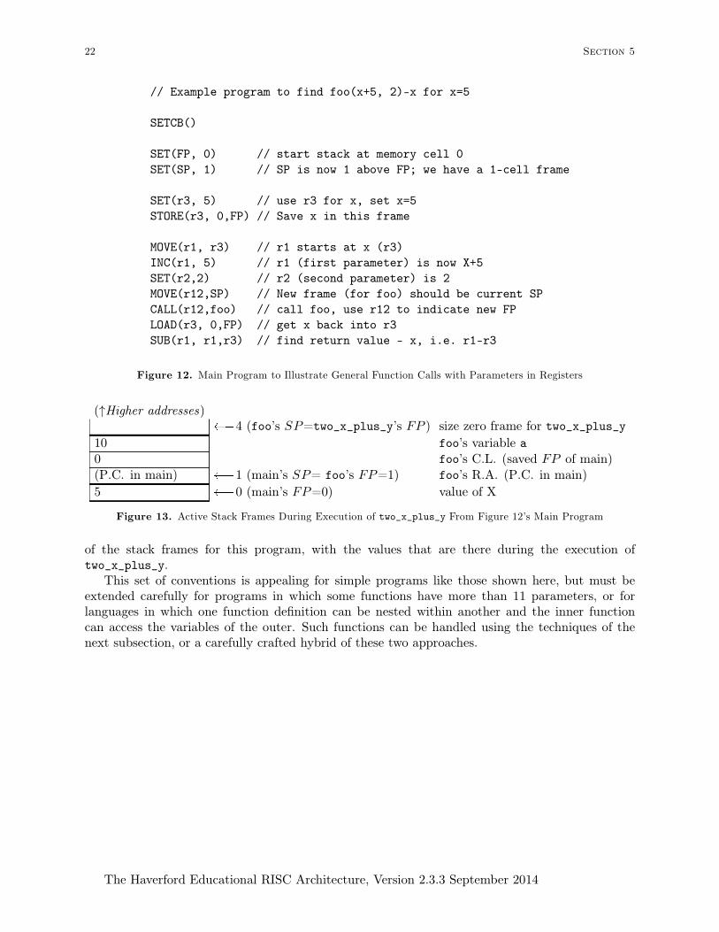
// Example program to find foo(x+5, 2)-x for x=5
SETCB()
SET(FP, 0) // start stack at memory cell 0
SET(SP, 1) // SP is now 1 above FP; we have a 1-cell frame
SET(r3, 5) // use r3 for x, set x=5
STORE(r3, 0,FP) // Save x in this frame
MOVE(r1, r3) // r1 starts at x (r3)
INC(r1, 5) // r1 (first parameter) is now X+5
SET(r2,2) // r2 (second parameter) is 2
MOVE(r12,SP) // New frame (for foo) should be current SP
CALL(r12,foo) // call foo, use r12 to indicate new FP
LOAD(r3, 0,FP) // get x back into r3
SUB(r1, r1,r3) // find return value - x, i.e. r1-r3
Figure 12. Main Program to Illustrate General Function Calls with Parameters in Registers
(↑Higher addresses)� 4 (foo’s SP=two_x_plus_y’s FP ) size zero frame for two_x_plus_y
10 foo’s variable a0 foo’s C.L. (saved FP of main)(P.C. in main) � 1 (main’s SP= foo’s FP=1) foo’s R.A. (P.C. in main)
5 � 0 (main’s FP=0) value of X
Figure 13. Active Stack Frames During Execution of two_x_plus_y From Figure 12’s Main Program
of the stack frames for this program, with the values that are there during the execution oftwo_x_plus_y.
This set of conventions is appealing for simple programs like those shown here, but must beextended carefully for programs in which some functions have more than 11 parameters, or forlanguages in which one function definition can be nested within another and the inner functioncan access the variables of the outer. Such functions can be handled using the techniques of thenext subsection, or a carefully crafted hybrid of these two approaches.
22 Section 5
The Haverford Educational RISC Architecture, Version 2.3.3 September 2014
5.5.2 Function Call with Parameters on Stack, “Callee-Save” Registers
When a function’s parameters outnumber the available registers, some parameters can be placeddirectly into the stack frame by the calling function, rather than placed in registers. Placingparameters and local variables in the stack frame also enables the traditional approach to pro-viding “lexically scoped” access by functions defined within the body of another function in ahigh-level language (for details, see “lexical scoping” in a compiler design textbook, e.g. [App98]).
To avoid the complexities of placing some parameters in memory and others in registers, therest of this section illustrates the use of a pure “parameters on the stack” approach. The stackframe will also be used for other information, such as return addresses, control links, and thestatic links (S.L.) that are used to implement lexical scoping. The examples of this section com-bine this “parameters on the stack” approach with the “callee-save” rather than “caller-save” con-vention for saving registers, as discussed below.
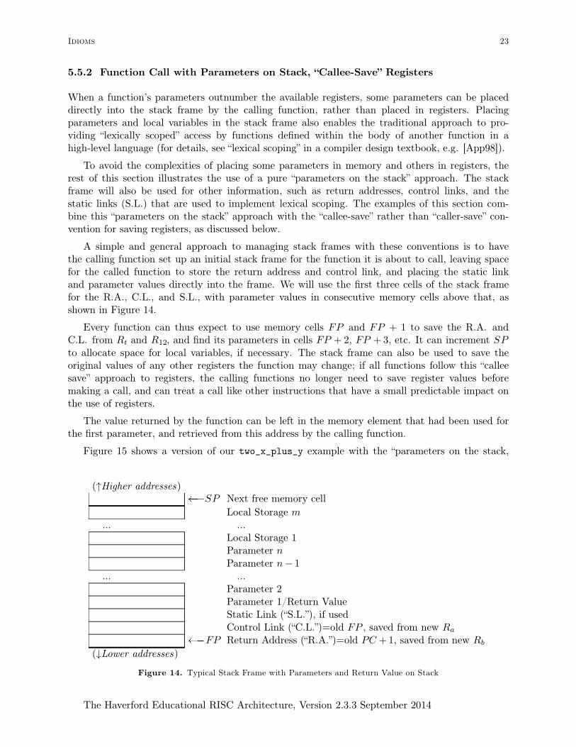
A simple and general approach to managing stack frames with these conventions is to havethe calling function set up an initial stack frame for the function it is about to call, leaving spacefor the called function to store the return address and control link, and placing the static linkand parameter values directly into the frame. We will use the first three cells of the stack framefor the R.A., C.L., and S.L., with parameter values in consecutive memory cells above that, asshown in Figure 14.
Every function can thus expect to use memory cells FP and FP + 1 to save the R.A. andC.L. from Rt and R12, and find its parameters in cells FP + 2, FP + 3, etc. It can increment SPto allocate space for local variables, if necessary. The stack frame can also be used to save theoriginal values of any other registers the function may change; if all functions follow this “calleesave” approach to registers, the calling functions no longer need to save register values beforemaking a call, and can treat a call like other instructions that have a small predictable impact onthe use of registers.
The value returned by the function can be left in the memory element that had been used forthe first parameter, and retrieved from this address by the calling function.
Figure 15 shows a version of our two_x_plus_y example with the “parameters on the stack,
(↑Higher addresses)�SP Next free memory cell
Local Storage m
... ...Local Storage 1Parameter nParameter n− 1
... ...Parameter 2Parameter 1/Return ValueStatic Link (“S.L.”), if usedControl Link (“C.L.”)=old FP , saved from new Ra
� FP Return Address (“R.A.”)=old PC +1, saved from new Rb
(↓Lower addresses)
Figure 14. Typical Stack Frame with Parameters and Return Value on Stack
Idioms 23
The Haverford Educational RISC Architecture, Version 2.3.3 September 2014

callee-save of registers” conventions. Although the code in Figures 15 and 17 does not make useof a static link, space is left for one on the stack frame so that the code matches Figure 14. Thistwo_x_plus_y starts with a standard “preamble” for these conventions, in which it increases itsstack frame size (via INC(SP, 2)), saves R.A. and C.L. as described above, and also saves theregisters it will overwrite. It then retrieves its parameters from positions 3 and 4 in its stackframe (where they will have been placed by the function calling two_x_plus_y), computes itsresult, and saves its result into its stack frame. It concludes with a standard “post-amble”,restoring the registers and SP .
Note that the function in Figure 15 could be optimized to be smaller and faster by skippingthe steps of saving and restoring Rt and R12, since it does not overwrite these values. Such opti-mization must be undertaken with care, especially when Rt is involved, since Rt may be over-written by MULT, by pseudo-operations such as NOT, or by assembler-generated branches to labels.
To perform a function call using the conventions discussed above, a function allocates spacefor the function to be called, as illustrated in Figure 16 (the new function’s frame will occupy theshaded region). This allocation is done by simply incrementing SP , though typically the functionwill first save the old SP in R12 for use in the upcoming CALL instruction. The calling function
// Translation of a high-level-language function two_x_plus_y:
// int two_x_plus_y(x : int, y : int) : int = x+x+y
LABEL(two_x_plus_y)
// FIRST, make space to save r1 and r2 and then save Rt, R12, and them
INC(SP, 2)
STORE(Rt, 0,FP) // Return address, i.e. PC+1 from before CALL
STORE(R12, 1,FP) // Control Link, i.e. FP from before the CALL
STORE(r1, 5,FP) // skip FP+3 and FP+4, where a and b will be...
STORE(r2, 6,FP) // ... and save r1 and r2 in FP+5/FP+6
// Load "x" and "y" from stack frame (calling func. put them there)
LOAD(r1, 3,FP) // r1 = x
LOAD(r2, 4,FP) // r2 = y
// Compute the result
ADD(r1, r1,r1) // r1 = x+x
ADD(r1, r1,r2) // r1 = x+x+y
// Store the result where the caller of two_x_plus_y will find it
STORE(r1, 3,FP)
// FINALLY, restore registers (including Rt and R12) and return
LOAD(r2, 6,FP) // Restore r2
LOAD(r1, 5,FP) // Restore r1
LOAD(Rt, 0,FP) // Restore Rt to provide R.A. for return
LOAD(R12, 1,FP) // Restore R12 (C.L.) to provide old FP for return
DEC(SP, 2)
RETURN(R12, Rt)
Figure 15. Example Function two_x_plus_y, Illustrating Stack Frame Maintenance and Usage
24 Section 5
The Haverford Educational RISC Architecture, Version 2.3.3 September 2014

then sets up the called function’s parameters and static link (if needed) in memory cells aboveR12, and issues the CALL instruction. It can then retrieve the result from memory cell R12+3.
Figure 17 gives an example call to two_x_plus_y, from a function foo illustrated by pseudo-code above the function. In addition to the steps already shown in Figure 15 (standard preamble,access to parameters, standard post-amble), Figure 17 shows the creation of a new stack frame,definition of parameters, and retrieval of the value returned by two_x_plus_y. Note foo can stillrely on the value of a that it left in R1 before making the call, since two_x_plus_y will havesaved and restored this value.
Note that the save and restore of Rt and R12 are needed in Figure 17, unlike Figure 15. Wecould optimize Figure 17 by combining the two increments of SP , and likewise combining thetwo decrements. This would slightly shorten the function, possibly at the cost of some clarity.
(↑Higher addresses)�SP Next free memory cell
Parameter k for function to be called... ...
Parameter 2 for function to be calledParameter 1/Return Value for function to be called(space for S.L. of function to be called, if S.L. used)(space for C.L. of function to be called)
�R12 (space for R.A. of function to be called)Local Storage m
... ...Local Storage 1Parameter nParameter n− 1
... ...Parameter 2Parameter 1/Return ValueStatic Link (“S.L.”), if usedControl Link (“C.L.”), i.e., old FP saved from new Ra
� FP Return Address (“R.A.”), saved from new Rb
(↓Lower addresses)
Figure 16. Typical Stack Frame with Parameters and Return Value on Stack, Just Before a CALL
Idioms 25
The Haverford Educational RISC Architecture, Version 2.3.3 September 2014

// Translation of foo (single precision, assuming CB set)
// int foo(a : int, b : int) : int = two_x_plus_y(a+b, b-a+75) * a
LABEL(foo)
// FIRST, make space to save r1 and r2 and then save Rt, R12, and them
INC(SP, 2)
STORE(Rt, 0,FP) // Return address
STORE(R12, 1,FP) // Control Link
STORE(r1, 5,FP) // skip FP+3 and FP+4, where a and b will be
STORE(r2, 6,FP)
// THEN the body of foo: compute two_x_plus_y(a+b, b-a+75) * a
// For the call, create space for 3 links and 2 parameters,
// remembering old SP in R12:
MOVE(R12, SP)
INC(SP, 5)
// and set up parameters a+b and b-a+75
LOAD(r1, 3,FP) // R1 = a (from memory cell FP+3)
LOAD(r2, 4,FP) // R2 = b
ADD(Rt, r1,r2) // Rt = a+b
STORE(Rt, 3,R12) // 1st parameter at R12+3, i.e. CALLED FUNC’S FP+3
SUB(r2, r2,r1) // R2 = b-a
SETLO(Rt, 75)
ADD(r2, r2,Rt) // R2 = b-a+75
STORE(r2, 4,R12) // establish 2nd parameter at R12+4
// and do the call
CALL(R12, two_x_plus_y)
// AFTER the call, retrieve result and multiply by "a"
LOAD(r2, 3,R12) // R2 = result retured FROM CALLED FUNC’S FRAME
// now that we have the returned value, we can shrink the stack back down:
DEC(SP, 5) // could use MOVE(SP, R12)
// NOTE that r1 is still "a" from before the call:
MULT(r1, r2,r1)
// Save the result where the caller of ’foo’ will find it
STORE(r1, 3,FP) // Put return value over 1st parameter
// FINALLY, restore registers (including Rt and R12) and return
LOAD(r2, 6,FP) // Restore r2
LOAD(r1, 5,FP) // Restore r1
LOAD(Rt, 0,FP) // Restore Rt to provide R.A. for return
LOAD(R12, 1,FP) // Restore R12 (C.L.) to provide old FP for return
DEC(SP, 2)
RETURN(R12, Rt)
Figure 17. Calling A Function, with Parameters on Stack
26 Section 5
The Haverford Educational RISC Architecture, Version 2.3.3 September 2014

SETCB()
MOVE(R12, SP)
INC(SP, 5)
SET(r7,2)
STORE(r7, 3,R12) // parameter 1 = 2
SET(r7,10)
STORE(r7, 4,R12) // parameter 2 = 10
CALL(R12, foo)
LOAD(r1, 3,R12) // retrieve result
DEC(SP, 5)
Figure 18. Main Program to Call the Function foo in Figure 17 or the Upcoming Figure 21.
To complete this example, Figure 18 gives a main program to call foo with the parameters 10and 2, and Figure 19 shows a memory layout diagram of the stack during the execution of thisprogram, at the instant just before the DEC(SP,2) in two_x_plus_y, assuming the main functionof Figure 18 is executed when the HERA microprocessor starts up, with all registers (includingFP and SP ) being 0, and thus with a zero-size stack frame for the main program. Memory cellswith contents marked “*” are addresses of instructions in the program—these can’t be determinedwithout knowing how the code from the various figures is laid out in the address space of theinstruction memory).
To summarize the specifics of this convention (including the choice of R12 for the new func-tion’s frame pointer, and Rt for the address of the new function), to call a function, we:
• Set R12←SP and increment SP to allocate initial stack frame (for links and parameters)
• Put the parameters on the stack above 3 spaces for links (i.e., starting at R12+3)
• Set up the static link, if one is used
• Issue the CALL instruction
• After the call, the return value can be retrieved from R12+3, and SP decremented.
(↑Higher addresses)�14 (two_x_plus_y’s SP ) Next free memory cell
67 two_x_plus_y’s saved R2
10 �12 (two_x_plus_y’s initialSP ) two_x_plus_y’s saved R1
67 two_x_plus_y’s parameter y91 (was 12) two_x_plus_y’s result (was x)
two_x_plus_y’s S.L.0 two_x_plus_y’s C.L. (foo’s FP )* � 7 (two_x_plus_y’s FP ) two_x_plus_y’s R.A. (into foo)
0 foo’s saved R2
0 � 5 (foo’s initial SP ) foo’s saved R1
10 foo’s parameter b2 foo’s parameter a
foo’s S.L. (undefined)0 foo’s C.L. (saved FP of main)* � 0 (foo’s FP=0) foo’s R.A. (into main)
Figure 19. Stack Layout for Figures 17, 15, and 18 Just Before DEC(SP, 2) in two_x_plus_y.
Idioms 27
The Haverford Educational RISC Architecture, Version 2.3.3 September 2014
To define a function to be called with these conventions, we
• Increment SP to make space for local storage
• Save registers, including Rt (return address) and R12 (control link, i.e. the old FP )
• Give the function body (in which parameters can be from the stack frame, e.g. FP +3)
• Store the return value at FP +3
• Restore saved registers, including the C.L. into R12 and R.A. into Rt, and decrement SP
• RETURN from the function
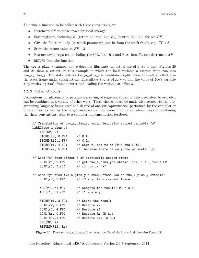
The two_x_plus_y example above does not illustrate the actual use of a static link. Figures 20and 21 show a variant on this example in which the local variable a escapes from foo intotwo_a_plus_y. The static link for two_a_plus_y is established right before the call, at offset 2 inthe stack frame under construction. This allows two_a_plus_y to find the value of foo’s variablea by retrieving foo’s frame pointer and loading the variable at offset 3.
5.5.3 Other Options
Conventions for placement of parameters, saving of registers, choice of which registers to use, etc.,can be combined in a variety of other ways. These choices must be made with respect to the pro-gramming language being used and degree of analysis/optimization performed by the compiler orprogrammer, as well as the target architecture. For more information about ways of combiningthe these conventions, refer to a compiler implementation textbook.
// Translation of two_a_plus_y, using lexically scoped variable "a"
LABEL(two_a_plus_y)
INC(SP, 2)
STORE(Rt, 0,FP) // R.A.
STORE(R12,1,FP) // C.L.
STORE(r1, 4,FP) // Save r1 and r2 at FP+4 and FP+5,
STORE(r2, 5,FP) // because there is only one parameter (y)
// Load "a" from offset 3 of statically scoped frame
LOAD(r1, 2,FP) // get two_a_plus_y’s static link, i.e., foo’s FP
LOAD(r1, 3,r1) // r1 now is "a"
// Load "y" from two_a_plus_y’s stack frame (as in two_x_plus_y example)
LOAD(r2, 3,FP) // r2 = y, from current frame
ADD(r1, r1,r1) // Compute the result: r1 = a+a
ADD(r1, r1,r2) // r1 = a+a+y
STORE(r1, 3,FP) // Store the result
LOAD(r2, 5,FP) // Restore r2
LOAD(r1, 4,FP) // Restore r1
LOAD(Rt, 0,FP) // Restore Rt (R.A.)
LOAD(R12,1,FP) // Restore R12 (C.L.)
DEC(SP, 2)
RETURN(R12, Rt)
Figure 20. Function two_a_plus_y, Illustrating the Use of the Static Link (see also Figure 21).
28 Section 5
The Haverford Educational RISC Architecture, Version 2.3.3 September 2014

// Translation of main function foo, setting up to use lexical scoping
// int foo(int a, int b) =
// let two_a_plus_y(y : int): int = a+a+y
// in two_a_plus_y(b-a+75) * a
// (once again, assuming single precision, and carry-block is set)
LABEL(foo)
// Standard preamble
INC(SP, 2)
STORE(Rt, 0,FP)
STORE(R12,1,FP)
STORE(r1, 5,FP)
STORE(r2, 6,FP)
// Allocate space for new frame, define ONE parameter "y"
MOVE(R12, SP)
INC(SP, 4)
LOAD(r1, 3,FP) // R1 = a
LOAD(r2, 4,FP) // R2 = b
SUB(r2, r2,r1) // R2 = b-a
SETLO(Rt, 75)
ADD(r2, r2,Rt) // R1 = b-a+75
STORE(r2, 3,R12)
// Build the static link for two_a_plus_y (points to foo’s frame),
STORE(FP, 2,R12) // CREATE STATIC LINK FOR two_a_plus_y
CALL(R12,two_a_plus_y)
LOAD(r2, 3,R12) // Retrieve the result
DEC(SP, 4)
MULT(r1, r1,r2) // Multiply by "a"
STORE(r1, 3,FP) // Save result as return value
// Standard postable
LOAD(r2, 6,FP)
LOAD(r1, 5,FP)
LOAD(Rt, 0,FP)
LOAD(R12, 1,FP)
DEC(SP, 2)
RETURN(R12, Rt)
Figure 21. Function Calls with Parameters on Stack and an Escaping Local Variable
Idioms 29
The Haverford Educational RISC Architecture, Version 2.3.3 September 2014

Bibliography
[App98] Andrew W. Appel. Modern Compiler Implementation in C . Cambridge University Press, 1998.
[Han04] Jeffery P. Hansen. TKGate, a graphical editor and event-driven simulator for digital circuits with atcl/tk-based interface. http://www.tkgate.org/, 1987-2004.
[HP07] John Hennessy and David Patterson. Computer Architecture - A Quantitative Approach . Morgan Kauf-mann, fourth edition, 2007.
[Man88] M. Morris Mano. Computer Engineering: Hardware Design . Prentice Hall, 1988.
[Uni12] Unicode, Inc. The Unicode standard 6.1. http://www.unicode.org/charts/PDF/U0000.pdf, 1991-2012.
[Won03] David G. Wonnacott. HERA: The Haverford Educational RISC Architecture. http:www.cs.haver-
ford.edu/software/HERA/, 2003.
[Won06] David Wonnacott. Unifying the undergraduate applied CS curriculum around a simplified micropro-cessor architecture. In Proceedings of the 22nd Annual Consortium for Computing Sciences in CollegesEastern Conference (CCSC-E 06), October 2006.
30 Section
The Haverford Educational RISC Architecture, Version 2.3.3 September 2014