the groundwater performance assessment project quality ... · pnnl-15014, rev. 1 the groundwater...
TRANSCRIPT

PNNL-15014, Rev. 1
The Groundwater Performance Assessment Project Quality Assurance Plan May 2006 Prepared by Pacific Northwest National Laboratory Richland, Washington for the U.S. Department of Energy under Contract DE-AC05-76RL01830

DISCLAIMER
This report was prepared as an account of work sponsored by an agency of the United States Government. Reference herein to any specific commercial product, process, or service by trade name, trademark, manufacturer, or otherwise does not necessarily constitute or imply its endorsement, recommendation, or favoring by the United States Government or any agency thereof, or Battelle Memorial Institute.
PACIFIC NORTHWEST NATIONAL LABORATORY operated by BATTELLE
for the UNITED STATES DEPARTMENT OF ENERGY
under Contract DE-AC05-76RL01830
Printed in the United States of America
Available to DOE and DOE contractors from the Office of Scientific and Technical Information, P.O. Box 62, Oak Ridge, TN 37831;
prices available from (615) 576-8401.
Available to the public from the National Technical Information Service, U.S. Department of Commerce, 5285 Port Royal Rd., Springfield, VA 22161
This document was printed on recycled paper.

PNNL-15014, Rev. 1
The Groundwater Performance Assessment Project Quality Assurance Plan May 2006 Prepared for the U.S. Department of Energy under Contract DE-AC05-76RL01830 Pacific Northwest National Laboratory Richland, Washington 99352

iii
Summary
U.S. Department of Energy (DOE) has monitored groundwater on the Hanford Site since the 1940s to help determine what chemical and radiological contaminants have made their way into the groundwater. As regulatory requirements for monitoring increased in the 1980s, there began to be some overlap between various programs. DOE established the Groundwater Performance Assessment Project (groundwater project) in 1996 to ensure protection of the public and the environment while improving the efficiency of monitoring activities. The groundwater project is designed to support all groundwater monitoring needs at the site, eliminate redundant sampling and analysis, and establish a cost-effective hierarchy for groundwater monitoring activities.
This document provides the quality assurance guidelines that will be followed by the groundwater project. This QA Plan is based on the QA requirements of DOE Order 414.1C, Quality Assurance, and 10 CFR 830, Subpart A--General Provisions/Quality Assurance Requirements as delineated in Pacific Northwest National Laboratory’s Standards-Based Management System. In addition, the groundwater project is subject to the Environmental Protection Agency (EPA) Requirements for Quality Assurance Project Plans (EPA/240/B-01/003, QA/R-5). The groundwater project has determined that the Hanford Analytical Services Quality Assurance Requirements Documents (HASQARD, DOE/RL-96-68) apply to portions of this project and to the subcontractors. HASQARD requirements are discussed within applicable sections of this plan.

v
Contents
Summary ................................................................................................................................................ iii 1.0 Quality Assurance Plan Distribution............................................................................................ 1 2.0 Introduction.................................................................................................................................. 1 2.1 Title ............................................................................................................................. 1 2.2 Client ............................................................................................................................. 1 2.3 Authorizing Document ..................................................................................................... 1 2.4 Quality Assurance Requirements...................................................................................... 1 2.5 Special Requirements or Specifications............................................................................ 1 2.6 Project Scope .................................................................................................................... 2 2.7 Change Control ................................................................................................................. 6 3.0 Project Organization and Responsibilities ................................................................................... 6 3.1 Responsibilities of Key Personnel .................................................................................... 6 3.2 Other Work Services......................................................................................................... 9 3.2.1 Analytical Services .............................................................................................. 10 3.2.2 Sampling Services ............................................................................................... 11 3.2.3 Well Drilling, Sampling, and Construction Services........................................... 12 3.2.4 Geophysical Logging Services ............................................................................ 12 3.3 Sample Analysis by Project Staff ..................................................................................... 11 3.4 Field Measurements .......................................................................................................... 13 4.0 Data Quality Objectives ............................................................................................................... 12 5.0 Procedures.................................................................................................................................... 12 5.1 Test Planning and Performance ........................................................................................ 13 5.1.1 Developing the Test Plan..................................................................................... 13 5.1.2 Test Performance ................................................................................................. 14 5.2 Sampling Procedures ........................................................................................................ 14 5.2.1 Groundwater Sample Collection.......................................................................... 15 5.2.2 Project Procedures ............................................................................................... 16 5.2.3 Water Level Procedures....................................................................................... 16 5.2.4 Analytical Procedures.......................................................................................... 16 5.2.5 Calibration Procedures......................................................................................... 17 5.2.6 Seismic Monitoring Procedures........................................................................... 17 5.2.7 Well Drilling and Construction Procedures......................................................... 17 5.2.8 Sediment and Water Sample Collection Procedures ........................................... 18 5.2.9 Geophysical Logging Procedures ........................................................................ 168 6.0 Data Reduction, Verification, and Reporting............................................................................... 17 6.1 Data Reduction ................................................................................................................. 17 6.2 Sample Data Tracking and Verification ........................................................................... 17 6.3 Sample Data and Tracking for Soil and Sediment Samples ............................................. 21 6.4 Data Reporting.................................................................................................................. 20 7.0 Analytical Quality Control Checks .............................................................................................. 21 7.1 Internal Quality Control Samples ..................................................................................... 21 7.2 External Quality Control Samples .................................................................................... 21 8.0 Assessments ................................................................................................................................. 21 8.1 Assessment Planning ........................................................................................................ 22 8.2 Subcontractor Assessments............................................................................................... 25 9.0 Preventive Equipment Maintenance ............................................................................................ 25

vi
10.0 Specific Routine Procedures Used to Assess Data Precision, Accuracy, and Completeness ...... 25 11.0 Corrective Action......................................................................................................................... 26 11.1 Project Corrective Actions Resulting from Assessments ................................................. 26 11.2 Unplanned Deviations....................................................................................................... 26 11.3 Planned Deviations ........................................................................................................... 26 11.4 Measuring and Test Equipment Calibration Discrepancies.............................................. 26 12.0 Quality Assurance Reports to Management................................................................................. 27 13.0 Records ........................................................................................................................................ 27 13.1 Records Control ................................................................................................................ 27 13.2 Records Transfer to Storage ............................................................................................. 29 14.0 Procurement Control .................................................................................................................... 29 14.1 Groundwater Sampling ..................................................................................................... 29 14.2 Groundwater Analytical Services ..................................................................................... 29 14.3 Internal Services ............................................................................................................... 30 14.4 Sediment Analytical Services.......................................................................................... 28 15.0 Staff Training ............................................................................................................................... 29 16.0 Software Control .......................................................................................................................... 30 17.0 Nonconformances and Deficiencies............................................................................................. 30 18.0 Document Control........................................................................................................................ 31 18.1 Project QA Plan Control ................................................................................................... 31 18.2 Technical Procedure Control ............................................................................................ 31 18.3 Administrative Procedure /Instruction Preparation and Control....................................... 34 18.4 Groundwater Monitoring Plans ........................................................................................ 34 18.4.1 RCRA Interim-Status Plans................................................................................. 34 18.4.2 RCRA Final-Status Plans .................................................................................... 34 18.4.3 CERCLA Sampling and Analysis Plans.............................................................. 34 18.4.4 Other Monitoring Plans ....................................................................................... 35 19.0 References.................................................................................................................................... 35 Appendix – Groundwater Performance Assessment Project Quality Control Plan ............................... A.1
Figures
1. Number of Wells Sampled....................................................................................................................... 3 2. Number of Wells Analyzed...................................................................................................................... 3 3. Hanford Site Groundwater Interest Areas (roughly comparable to the groundwater operable units) ..... 4 4. Regulated Units on the Hanford Site Requiring Groundwater Monitoring under the Resource
Conservation and Recovery Act ............................................................................................................ 5 5. Project Interfaces ..................................................................................................................................... 7 6. Data Flow Diagram................................................................................................................................ 18 7. Self-Assessment Planning Form ............................................................................................................ 23 8. Self-Assessment Results ........................................................................................................................ 24 9. Interim Change Notice ........................................................................................................................... 32

1
1.0 Quality Assurance Plan Distribution
Pacific Northwest National Laboratory (PNNL) Document Control will distribute this Quality Assurance (QA) Plan internally to PNNL, the U.S. Department of Energy (DOE) Reading Room and Technical Library. The project manager will determine the distribution list. Also, the QA Plan will be published in accordance with the Standards-Based Management System (SBMS) subject area, Publishing Scientific and Technical Information (PNNL 2002).
2.0 Introduction
2.1 Title
The Groundwater Performance Assessment Project Quality Assurance Plan.
2.2 Client
U.S. Department of Energy, Richland Operations Office, Richland, Washington.
2.3 Authorizing Document
PBS# RL-0030 WBS# 4.2.2.20 – Groundwater Performance Assessment Project
This project has been ongoing since fiscal year (FY) 1996. Work has been authorized by the specified multi-year program plans.
2.4 Quality Assurance Requirements
The project Quality Assurance Program is based on the QA requirements of DOE Order 414.1C, Quality Assurance, and 10 CFR 830, Subpart A--General Provisions/Quality Assurance Requirements as delineated in the PNNL’s SBMS. In addition, the project is subject to the Environmental Protection Agency (EPA) Requirements for Quality Assurance Project Plans (EPA/240/B-01/003, QA/R-5) per the Tri-Party Agreement (TPA; Ecology et al. 1989). Additionally, the Groundwater Performance Assessment Project has determined that the Hanford Analytical Services Quality Assurance Requirements Documents (HASQARD, DOE/RL-96-68) apply to portions of this project and to the subcontractors (HASQARD is currently being revised to incorporate the requirements in EPA/240/B-01/003, QA/R-5, 2001.). HASQARD requirements are discussed within applicable sections of this plan.
2.5 Special Requirements or Specifications
DOE Orders 435.1, Radioactive Waste Management, and 450.1, Environmental Protection Program, apply to the project to implement requirements of the Atomic Energy Act. Compliance and waste-cleanup timetables and implementation milestones are established in the Hanford Federal Facility Agreement and

2
Consent Order (TPA; Ecology et al. 1989) to achieve compliance with remedial action provisions of the Comprehensive Environmental Response, Compensation, and Liability Act (CERCLA) and the treatment, storage, and disposal (TSD) unit regulation and corrective action provisions of the Resource Conservation and Recovery Act (RCRA).
RCRA groundwater monitoring is driven by 40 CFR 264, 40 CFR 265, and WAC 173-303. Monitoring is also conducted to support the Washington State Waste Discharge Permit Program (WAC 173-216) and for solid waste landfills (WAC 173-304).
CERCLA groundwater monitoring is implemented by 40 CFR 300 and lower level agreements with the U.S. Environmental Protection Agency (EPA) via work plans, records of decisions, and TPA change control forms.
Selected groundwater monitoring plans (see Section 4.0) are based on applying the Data Quality Objectives Process, in accordance with Guidance on Systematic Planning Using the Data Quality Objectives Process (EPA/240/B-06/001, QA/G-4). Geostatistics have been used to evaluate monitoring networks. Sampling and Analysis Plans are reviewed and approved by regulatory agencies, and are reviewed annually and updated as necessary.
RCRA monitoring system design is fairly prescriptive for most TSD units, which are still in interim status. Quarterly sampling is required to establish background, semiannual sampling is required for indicator evaluation (detection), and quarterly sampling is required for sites that have impacted ground-water quality. Monitoring under final-status regulations allows site-specific constituents of concern to be evaluated. These regulations also allow provisions for alternative statistics that account for site condi-tions. The TPA provides schedules for incorporating TSD units into the Hanford Facility RCRA Permit (Ecology 1994). Sites in final status have monitoring requirements stipulated in permit conditions. Notice-of-Deficiency comments are provided by Washington State Department of Ecology (Ecology), and are addressed in workshops with technical and permit staff. Selection of well locations are negotiated and made through TPA Milestone agreements.
The two pie chart graphs (Figures 1 and 2) show the number of wells sampled by location and number of analyses conducted in FY 2005 (considered a typical year).
2.6 Project Scope
DOE has monitored groundwater on the Hanford Site since the 1940s to help determine what chemical and radiological contaminants have made their way into the groundwater. As regulatory requirements for monitoring increased in the 1980s, there began to be some overlap between various programs. DOE established the Groundwater Performance Assessment Project (groundwater project) in 1996 to ensure protection of the public and the environment while improving the efficiency of monitoring activities. The groundwater project is designed to support all groundwater monitoring needs at the site, eliminate redundant sampling and analysis, and establish a cost-effective hierarchy for groundwater monitoring activities.

3
Figure 1. Number of Wells Sampled
Figure 2. Number of Wells Analyzed
Contamination may reach the Columbia River by moving down through the vadose zone, into the groundwater, and then into the river. The analysis of groundwater samples helps determine the potential effects that contaminants could have on human health and the environment. DOE works with the regulatory agencies, such as EPA and Ecology, to make cleanup decisions based on sound technical information and the technical capabilities available.
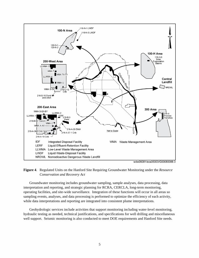
A map of the Hanford Site showing groundwater interest areas is shown in Figure 3. The ground-water interest areas are roughly comparable to groundwater operable units identified under CERCLA. Figure 4 shows the regulated units requiring groundwater monitoring under RCRA.

4
Figure 3. Hanford Site Groundwater Interest Areas (roughly comparable to the groundwater operable units)
5
Figure 4. Regulated Units on the Hanford Site Requiring Groundwater Monitoring under the Resource Conservation and Recovery Act
Groundwater monitoring includes groundwater sampling, sample analyses, data processing, data interpretation and reporting, and strategic planning for RCRA, CERCLA, long-term monitoring, operating facilities, and site-wide surveillance. Integration of these functions will occur in all areas so sampling events, analyses, and data processing is performed to optimize the efficiency of each activity, while data interpretations and reporting are integrated into consistent plume interpretations.
Geohydrologic services include activities that support monitoring including water-level monitoring, hydraulic testing as needed, technical justifications, and specifications for well drilling and miscellaneous well support. Seismic monitoring is also conducted to meet DOE requirements and Hanford Site needs.
6
Work is also conducted for the remedial investigation/feasibility study (RI/FS) process under CERLCA. Activities in addition to those discussed above include sediment sample collection and analysis, down-hole geophysical logging, and civil surveying of completed wells.
2.7 Change Control (Scope, Schedule, Budget)
The project scope, schedule, and budget baseline are compiled, tracked, and reported using a project control system in accordance with DOE direction.
Changes in work scope, schedule, or budget may be necessary during the year. Changes may be requested of subcontractors by PNNL that will result in a change to the statement of work (SOW) due to revisions of work scope, schedule, and/or budget. These changes will be documented in revisions or addendums to the existing SOW and a PNNL Subcontracts Supplement Form shall be completed.
Administrative changes requested of subcontractors that are approved by Task Leaders may be made by verbal or electronic message authorization. Written documentation of the verbal changes and electronic messages should be maintained in the permanent project files. These changes may only be made if technical work scope and budget are not affected significantly.
3.0 Project Organization and Responsibilities
Line authority, quality assurance authority and support within PNNL, and client interfaces are shown organizationally in Figure 5. The responsibilities of key PNNL personnel are summarized in Section 3.1.
Changes to organizational/interface structures shown in Figure 5 that do not reflect a change in the overall scope of the activities or a change of requirements will not require a QA Plan revision but will be incorporated into the next required revision of the QA Plan.
3.1 Responsibilities of Key Personnel
• Project Manager — provides overall direction to task managers and project personnel within PNNL necessary to accomplish all project objectives, including development and completion of technical work scope; coordinates and executes project controls associated with scope, schedule, and budget baselines; reports on project status; assures that the project is properly staffed with technically qualified personnel; serves as client interface for the project to assure that customer expectations are met in terms of quality, cost, and schedule; assures the QA Plan is implemented by project staff.
• Groundwater Monitoring Task Leader — oversees planning, control, communications, and progress reporting for the Monitoring Task; prepares task plan that includes work scope, resource requirements, cost baseline, and deliverables; assures technical quality of the work and that it is performed on schedule, within budget, and in accordance to plans, policies, and procedures; provides monthly reporting and support to the Project Manager in carrying out project management responsibilities; assigns and prioritizes responsibilities to sub-task managers for each of the sub-tasks; interfaces with DOE, other contractors, subcontractors, other Task Leaders, and the Groundwater Protection Program.

7
Figure 5. Project Interfaces
DL Stewart Subtask Leader
Sampling
MJ Hartman Subtask Leader
Monitoring Network Design
DL Stewart Subtask Leader Onsite Analyses
DL Stewart Subtask Leader Data Processing
DL Stewart Subtask Leader Offsite Analysis
RM Smith Subtask Leader
Interpretation & Reporting
SP Luttrell Groundwater
Monitoring Task
ST Reidel Seismic
Monitoring Task
TG Naymik CERCLA RI/FS
Activities
BA Williams Monitoring Well Installation Task
KA Klein Manager DOE-RL
MS McCormick Asst. Manager Central Plateau
BL Charboneau Manager
Groundwater Remediation
and Monitoring
RD Enge Director
Environment, Safety, Health and Quality
LV Kimmel Department
Manager Quality
TG Walker Project Quality
Engineer TJ Gilmore
Manager Field Hydrology &
Chemistry
JS Fruchter Project Mgr. Groundwater Performance
Assessment Project
RK Quinn Associate Laboratory Director
Environmental Technology Division
DD Dauble Manager
Natural Resources
LK Peters Director
Pacific Northwest National Laboratory
JG Morse Groundwater
Protection Project
Indians Tribes
Stakeholders
Public
Regulatory Agency
University of Washington Analyzes Seismic Data
Gupta (CFEST)
Eberline Services
Lionville Laboratories,, Inc Duratek Technical Services
Field Coordination & Supervision
Fluor Hanford NCOs Sample Collection &
Water Level Measurements
Flour Hanford RCTs
Severn Trent Laboratories (Richland/St. Louis)
FA Spane Subtask Leader
Hydro Assessment.
Duratek Field Hydrology Testing Support
Fluor Drilling, Sampling and
Well Construction

8
• Monitoring Network Design Sub-Task Leader — prepares and/or revises site-specific groundwater monitoring plans and assessment plans; coordinates RCRA, operational, site-wide surveillance, and CERCLA groundwater monitoring; identifies groundwater-monitoring plans and assessment plans that need to be written or revised, and provides the scope, cost baseline, and schedule for the work; assigns staff to produce the reports, coordinate schedules, and review plans; assures technical quality of the work and that it is performed on schedule, within budget, and in accordance to plans, policies, and procedures; provides monthly reports to the Task Leader.
• Sampling Sub-Task Leader — oversees planning, control, communications, and progress reporting for the Sampling Sub-Task; provides work scope, resource requirements, cost baseline, and deliver-ables to the Task Leader; requires subcontractor to comply with HASQARD (DOE/RL-96-68) Volumes 1, 2, and 3; oversees subcontractors providing sample collection; assures quality of the work and that it is performed on schedule, within budget, and in accordance to plans, policies, and procedures; provides monthly report to the Task Leader.
• Onsite Analyses Sub-Task Leader — oversees planning, control, communications, and progress reporting for the Onsite Analyses Sub-Task; provides work scope, resource requirements, cost baseline, and deliverables to the Task Leader; requires subcontractor to comply with HASQARD Volumes 1 and 4; oversees Hanford Site subcontractors providing analytical services; assures quality of the work and that it is performed on schedule, within budget, and in accordance to plans, policies, and procedures; provides monthly report to the Task Leader.
• Offsite Analyses Sub-Task Leader — oversees planning, control, communications, and progress reporting for the Offsite Analyses Sub-Task; provides work scope, resource requirements, cost baseline, and deliverables to the Task Leader; requires subcontractor to comply with HASQARD Volumes 1 and 4; oversees offsite subcontractors providing analytical services; assures quality of the work and that it is performed on schedule, within budget, and in accordance to plans, policies, and procedures; provides monthly report to the Task Leader.
• Data Processing Sub-Task Leader — oversees planning, control, communications, and progress reporting for the Data Processing Sub-Task; provides work scope, resource requirements, cost baseline, and deliverables to the Task Leader; assures sampling schedules are prepared, data veri-fication and tracking activities are conducted, and data are loaded into the Hanford Environmental Information System (HEIS) with appropriate checks; assures data are provided to the data users as requested; assures technical quality of the work and that it is performed on schedule, within budget, and in accordance to plans, policies, and procedures; provides monthly reports to the Task Leader.
• Interpretation and Reporting Sub-Task Leader — identifies groundwater characterization, assess-ment, and annual reports that need to be written or revised, and provides the scope, cost baseline, and schedule for the work; assigns staff to produce the reports, coordinate schedules, and review reports; assures technical quality of the work and that it is performed on schedule, within budget, and in accordance to plans, policies, and procedures; provides monthly reports to the Task Leader.
• Hydrologic Assessment Sub-Task Leader — characterizes the groundwater hydraulics in support of other project needs; prepares plans and reports of results; develops the scope, cost baseline, and schedule for the work; assigns staff to produce the reports, coordinate schedules, and review plans

9
and reports; assures technical quality of the work and that it is performed on schedule, within budget, and in accordance to plans, policies, and procedures.
• CERCLA RI/FS Task Leader — oversees conduct of RI/FS activities, in cooperation with DOE; assigns staff to produce work plans and reports; assures technical quality of the work and that it is performed on schedule, within budget, and in accordance to plans, policies, and procedures; provides monthly reports to the Task Leader. Also, oversees treatability testing and/or experiments related to the RI/FS activities.
• Well Installation Task Leader — plans wells to be installed and recommends wells for decommissioning; prepares data quality objectives (DQO) report and description of work for well installation and associated characterization needs; provides documentation of completed wells; provides direction for this task including direction of activities to accomplish task objectives and coordination of planning and organizing; assures technical quality of the work and that it is performed on schedule, within budget, and in accordance to plans, policies, and procedures.
• Seismic Monitoring Task Leader — provides direction of activities to accomplish task objectives and coordinates planning; assures technical quality of the work and that it is performed on schedule, within budget, and in accordance to plans, policies, and procedures; interfaces with DOE, other Hanford contractors, subcontractors, and the Emergency Response Team in planning and responding to a significant seismic event.
• Project Quality Engineer – provides guidance and direction to Project Manager, Task Leads, and project personnel within PNNL on PNNL QA Program requirements and other regulator QA requirements; performs surveillances on the sampling subcontractor activities to assure quality of their work; develops, updates, and approves QA Plan; reviews and approves appropriate work authorizing documents and applicable procedures; performs and reports self-assessments as directed by the Project Manager. A quality engineer certified to perform analytical laboratories audits will perform audits of analytical subcontractors on a periodic basis.
• Project Staff — assures technical quality of the work and that it is performed on schedule, within budget, and in accordance to plans, policies, and procedures; reports concerns such as unsafe conditions and stops work as necessary.
3.2 Other Work Services
Other work services for various portions of project work will be through the purchasing process. General scope of work, work requirements, specifications, and quality assurance requirements are communicated via a contracting mechanism to various subcontractors (see Section 14.0). Following is a list of subcontractors and the scope of their work for this project. Any change to this list not resulting in a change to scope, schedule, budget, or quality will be updated during the biennial review or revision to the QA Plan. SOW to subcontractors used for groundwater and sediment sampling and analysis will require compliance with the HASQARD (DOE/RL-96-68) and/or the EPA Requirements for Quality Assurance Project Plans (EPA/240/B-01/003, QA/R-5). The SOW will include instructions for inspecting/accepting supplies and consumables used for this project in accordance with HASQARD. SOW to subcontractors for drilling and well construction, borehole geophysical logging, and civil surveys will also be prepared.

10
The current subcontractors are listed below:
• Duratek Federal Services Northwest (Duratek) — provides daily coordination of groundwater sampling and water measurements, and support to hydrologic testing upon request.
• Fluor Hanford, Inc. (FHI) — performs routine groundwater sampling and water-level measurements, purgewater containment and disposal, radiological control technician support, and miscellaneous solid waste disposal. FHI also provides drilling, sediment and water sample collection related to drilling, and well construction services.
• Severn Trent Laboratories (Richland/St. Louis) — provides analytical services (primary provider).
• Eberline Services — provides analytical services (secondary provider).
• Lionville Laboratories — provides analytical services (secondary provider).
• University of Washington — analyzes and reports seismic data for the Eastern Washington Seismic Array.
• Stoller, Inc. – provides downhole geophysical logging services.
• Other subcontractors – may provide civil surveys, special analytical services, or other services.
3.2.1 Analytical Services
The analytical laboratories, both commercial and on-site laboratories, are responsible for preparing data reports that summarize the results of analyses and detailed data packages that include the following:
• Sample receipt and tracking documentation, including identification of the organization and individuals performing the analysis; names and signatures of the responsible analysts; sample holding time requirements; references to applicable chain-of-custody procedures; and dates of sample receipt, extraction (if applicable), and analysis.
• Quality control data, as appropriate for the methods used, including matrix spike/matrix spike duplicate data, recovery percentages, precision and accuracy data, laboratory blank data, and identification of any nonconformances that may have affected the laboratory’s measurement system during the time period in which the analysis was performed.
• Analytical results or data deliverables, including reduced data and identification of data qualifiers and contractually defined reporting comments.
These requirements as well as QA and technical requirements are specified in the SOW to the analytical laboratories. Also, the requirements for the hard copy and electronic data received from the analytical laboratories are specified in respective analytical subcontractor SOW.

11
3.2.2 Sampling Services
The sampling organization is responsible for (1) delivering samples to the laboratory, (2) delivering completed sampling and water-level paperwork to PNNL, and (3) preparing a monthly report summarizing the number of both successful and unsuccessful well trips, noting any problem with wells during the month, including deviations from schedule, and providing an estimate of costs by project for services performed. All activities associated with the sample collection, sample handling, sample labeling, and custody of the samples in the field shall be consistent with the recommendations and protocol provided in Chapter 4, Section 4.2 through 4.4 in RCRA Ground Water Monitoring Technical Enforcement Guidance Document (National Water Well Association 1986), SW-846 (EPA/SW-846), and the Handbook for Analytical Quality Control in Water and Wastewater Laboratories (EPA-600/4-79/019). One exception is that in most cases, subsamples for total metals are passed through 0.45 micron filter and collected in a bottle containing a small amount of nitric acid (pH < 2), a non-filtered subsample is not collected.
3.2.3 Well Drilling, Sampling, and Construction Services
FHI provides well-drilling and construction subcontractors and oversight on the Hanford Site. FHI is responsible for (1) well drilling design specifications and contract management, (2) site preparation and documentation requirements, (3) sediment and water sample collection during drilling, (4) supporting hydrologic tests conducted during drilling, and (5) well construction, development, and sample pump installation. Well construction will meet the requirements of WAC 173-160.
Well drilling and construction, sediment and water sampling, testing support, and associated quality requirements are specified in the SOW to FHI. Procedures and documentation requirements will be specified in the SOW. FHI may subcontract work activities provided the requirements in the SOW and the FHI QA Program are met by subcontractor(s).
3.2.4 Geophysical Logging Services
The geophysical logging requirements and associated quality requirements will be specified in the SOW. The requirements for the data deliverables will also be specified in the SOW.
3.3 Sample Analysis by Project Staff
Analytical activities conducted by the project staff in support of groundwater monitoring shall be conducted in accordance with in-house written standard operating procedures. Field measurements during aquifer tubes sampling will be conducted in accordance with in-house operating procedures. The project staff are responsible for preparing data reports that summarize the results of analyses, quality control data for the method used and identification of data qualifiers. The results and raw data will be included into the project records.
3.4 Field Measurements
Field measurements during well drilling will be conducted in accordance with FHI procedures, or other equivalent procedures, and as directed in the SOW.

12
4.0 Data Quality Objectives
The QA objectives for measurements generally applicable to groundwater, sediment and vadose monitoring investigations under the purview of this QA Plan are primarily related to (1) the definition of appropriate methods for chemical analysis of the analytes of interest and (2) the definition of limits and values for analytical precision and accuracy appropriate for the purposes of groundwater monitoring investigations at the Hanford Site. Detailed discussions of these analytical objectives and analytical methods with corresponding target values for detection limits, precision, and accuracy are provided in Appendix of this plan. The sediment analytical objectives and analytical methods with corresponding target values for detection limits, precision, and accuracy are provided in the ESL QA Plan. The geophysical logging objectives and methods with corresponding target values for detection limits, precision, and accuracy are provided in the work plans and/or the SOW for such activities. Specific data quality needs for individual investigations that are different than the minimum requirements established herein shall be addressed within individual groundwater monitoring plans. However, the groundwater monitoring plans must meet the minimum data quality requirements established within the Appendix to this plan. Other measurement considerations, accuracy requirements, units, and data recording and reporting protocols for instruments supporting stratigraphic characterization, aquifer testing and other types of field investigations shall be as specified in the applicable plans and/or procedures.
DQO developed in accordance with Guidance on Systematic Planning Using the Data Quality Objectives Process (EPA/240/B-06/001, QA/G-4) will be applied when preparing the following: groundwater monitoring plans for TSD units incorporated into the Hanford Facility RCRA Permit (Ecology 1994); groundwater quality assessment plans for RCRA TSD units that have impacted groundwater quality; and sampling and analysis plans for CERCLA groundwater operable units (initial versions only, not revisions for all the preceding). A draft DQO report will be developed by the responsible project scientist prior to review/discussion with regulatory agency staff. The final DQO report will be documented via a letter report and placed in the project file for the respective site.
The data quality requirements for work supporting CERCLA RI/FS activities will be identified in the sampling and analysis plans or investigation plans. These activities include, but are not limited to, sediment sampling and analysis, installation of new wells, geophysical logging, and temporary boreholes using direct push technology (DPT) or other means.
5.0 Test Plans and Procedures
Test Plans and Procedures are used to assure that activities affecting quality are performed consistently and correctly. Test Plans are prepared by PNNL staff to conduct a single experiment or test as identified below. Formal procedures will be developed for quality affecting work activities that are routinely performed.

13
5.1 Test Planning and Performance
Test plans will be used to document a single experimental or test (e.g., hydrologic field tests, vertical sampling) work activity.
5.1.1 Developing the Test Plan
The test plan shall contain the following information:
• A title and/or number including date or revision.
• Dated signatures of the Preparer, Technical Lead, Project Manager or Task Lead, and Quality Representative.
• Individual page identification (page ___ of ___).
The content of each test plan will depend on the scope of the test. The following is a brief description of mandatory and optional items to be considered in the preparation of the test plan:
• Purpose/Description (mandatory) – Provide a short narrative on the purpose of the experiment/test/activity. Example: The purpose of this test is to provide hydrologic property data at newly constructed monitoring wells located in the 200 West and 200 East Areas using slug testing, tracer-dilution testing, tracer-pump back testing, and pumping recovery testing.
• Prerequisites (mandatory) – List items, conditions, or other concerns that must be satisfied prior to beginning the test. Example: Prior to beginning the work activity, the staff must complete special training on other plans or procedures that will be used in conjunction with the test plan, special handling or storage requirements, special access or permits, and required records that need to be generated as the result of the work activity.
• Safety (mandatory) – Describe the hazards associated with the work such as physical agents (e.g., temperature, pressure, noise, electrical); hazardous environments (e.g., confined spaces, remote locations, heat/cold stress); and hazardous materials (e.g., flammables, corrosives, highly toxic, carcinogens). Describe the methods used to mitigate the hazards that were identified (e.g., personal protective equipment, time periods away from the hazard, alarms, location of nearest aid station).
• Materials and Equipment (optional) – List the materials and equipment that are necessary to complete the work.
• Measuring and Test Equipment (mandatory) – List the equipment that will be used to make the measurements; include the calibration requirements, system checks, and quality control checks in this section or in the work instructions section of the test plan.
• Pretest Verification (mandatory) – Determine if certain items of a test require verification prior to their use and indicate how the verification will be done.

14
Example: A tracer solution containing Br will be used throughout the test and the initial concentration shall be known. The solution shall be measured by the calibrated probe (as described above) and the concentration shall be recorded prior to injection.
• Documentation and Reporting (mandatory) – Describe where the data collected during the test should be documented (e.g., field record forms, laboratory record books, entered into a computer, downloaded from computer to hardcopy) or entered into HEIS. Additionally, describe what will be reported, to whom, and the due date(s).
• Work Instructions (mandatory) – Provide step-by-step instructions and/or non-sequential instruc-tions (whichever is more appropriate to the activity). Each step or instruction shall be as simple as possible but with sufficient detail so that individuals experienced in the technology or activity involved can easily understand. The following types of information should be considered for inclusion: administrative control hold points (i.e., where quality, radiological, or other approvals or actions are required before proceeding); cautions that indicate potentially hazardous situations which, if not avoided, may result in death, injury, or damage to facilities or equipment; and notes that call attention to supplemental information that assist the user in making decisions or improving work performance.
5.1.2 Test Performance
Tests will be performed in accordance with the test plans, which shall be available at the work location. The Technical Lead is responsible for assuring that the current version is used to perform the work.
If changes to the test plan are required during the execution of the work, the Technical Lead shall document the deviation and the justification or rationale for the change.
5.2 Procedures
5.2.1 Groundwater Sample Collection
Sampling will be done by Fluor Hanford Nuclear Chemical Operators (NCOs) under the supervision of Duratek. Quality requirements for sampling activities, including requirements for procedures, containers, transport, storage, chain of custody, and record requirements, are specified in a SOW to Duratek.
Procedures are designed to reduce variability between sampling events and obtain representative samples, thereby maintaining consistent quality during groundwater sampling. The quality of the sampling operations is important to the ultimate quality of the data that the laboratory will obtain by following standard analytical procedures.
To assure that samples of known quality are obtained, FHI and Duratek will be required to use controlled procedures based on standard methods for groundwater sampling whenever possible. The PNNL Sampling and Analysis Sub-Task Leader will assure that reviews are performed on procedures for technical quality and consistency. Assessments will be performed by PNNL to further assure that procedures are followed to maintain sample quality and integrity (see Section 8).
15
5.2.2 Project Procedures
Procedures will be developed in accordance with SBMS subject area, Procedures, Permits, and Other Work Instructions (PNNL 2004). Project staff will perform scheduling, data verification, data processing, and data management as described in Section 6 and by following the applicable internal technical procedures or instructions. Also, project staff will perform aquifer tube sampling, groundwater sampling, field measurements, water-level measurements, and aquifer testing by following the appropriate internal technical procedures.
5.2.3 Water-Level Procedures
Procedures for water-level measurements shall be in accordance with industry accepted standards, such as guidelines prepared by the U.S. Geological Survey (1977), updated as required for the latest advances in measuring equipment.
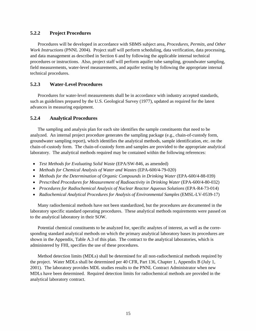
5.2.4 Analytical Procedures
The sampling and analysis plan for each site identifies the sample constituents that need to be analyzed. An internal project procedure generates the sampling package (e.g., chain-of-custody form, groundwater sampling report), which identifies the analytical methods, sample identification, etc. on the chain-of-custody form. The chain-of-custody form and samples are provided to the appropriate analytical laboratory. The analytical methods required may be contained within the following references:
• Test Methods for Evaluating Solid Waste (EPA/SW-846, as amended) • Methods for Chemical Analysis of Water and Wastes (EPA-600/4-79-020) • Methods for the Determination of Organic Compounds in Drinking Water (EPA-600/4-88-039) • Prescribed Procedures for Measurement of Radioactivity in Drinking Water (EPA-600/4-80-032) • Procedures for Radiochemical Analysis of Nuclear Reactor Aqueous Solutions (EPA-R4-73-014) • Radiochemical Analytical Procedures for Analysis of Environmental Samples (EMSL-LV-0539-17)
Many radiochemical methods have not been standardized, but the procedures are documented in the laboratory specific standard operating procedures. These analytical methods requirements were passed on to the analytical laboratory in their SOW.
Potential chemical constituents to be analyzed for, specific analytes of interest, as well as the corre-sponding standard analytical methods on which the primary analytical laboratory bases its procedures are shown in the Appendix, Table A.3 of this plan. The contract to the analytical laboratories, which is administered by FHI, specifies the use of these procedures.
Method detection limits (MDLs) shall be determined for all non-radiochemical methods required by the project. Water MDLs shall be determined per 40 CFR, Part 136, Chapter 1, Appendix B (July 1, 2001). The laboratory provides MDL studies results to the PNNL Contract Administrator when new MDLs have been determined. Required detection limits for radiochemical methods are provided in the analytical laboratory contract.

16
Sediment constituents to be analyzed for as well as the corresponding analytical methods and procedures will be passed on to the analytical laboratory by a SOW. The MDLs for sediment analysis shall be determined using the calculation provided in Chapter One of EPA/SW-846, as amended.
Administrative quality assurance processes and procedures (e.g., chain of custody, custody logs, sample handling, storage and disposal, training) will be required of the onsite and offsite analytical laboratories and will be specified in the SOW.
5.2.5 Calibration Procedures
The requirements for calibrating field and analytical laboratory instruments and maintain traceability to national or international standard (e.g., National Institute of Standards and Technology) is in accor-dance with Test Methods for Evaluating Solid Waste: Physical/Chemical Methods, EPA/SW-846 and HASQARD (DOE/RL-96-68). These requirements are passed to the subcontractors by a SOW. PNNL will periodically assess the use and effectiveness of procedures and systems for calibration of equipment with the subcontractors.
Instruments used by project staff that requires calibration by client, Category 1 or Category 2 instruments shall be calibrated in accordance with PNNL’s SBMS subject area, Calibration (PNNL 2005b).
5.2.6 Seismic Monitoring Procedures
Procedures will be developed in accordance with SBMS subject area, Procedures, Permits, and Other Work Instructions (PNNL 2004). Project staff will collect and process earthquake data in accordance with the applicable procedures.
5.2.7 Well Drilling and Construction Procedures
FHI will obtain the drilling company through their procurement process. A SOW to FHI specifies well drilling, characterization (aquifer and sediment sampling, etc.) and construction requirements. The well drilling, sediment samples collection, groundwater samples collection, water level measurements, and notification to perform geophysical logging/gyroscope well deviation survey is the responsibility of FHI. These activities will be performed to FHI procedures and/or to subcontractor procedures (e.g., conducting geophysical logging/gyroscope well deviation survey). FHI Health and Safety, and QA procedures and waste management procedures will be followed during the drilling activity. Scheduling sample bottle preparation, sample analysis and preparing associated paperwork is in accordance with PNNL’s groundwater procedures and is conducted at PNNL.
5.2.8 Sediment and Water Sample Collection Procedures
Sediment and water samples will be collected by or under the direction of FHI, and in accordance with FHI or subcontractor procedures. The quality requirements for sampling activities, including chain of custody, storage, and records requirements are specified in the Statement of Work (or well data sheet).

17
5.2.9 Geophysical Logging Procedures
Geophysical logging and gyroscope well deviation surveys will be performed by Stoller, Inc., using their procedures, and as directed in the SOW.
6.0 Data Reduction, Verification, and Reporting
6.1 Data Reduction
Groundwater data measured during groundwater sampling and from laboratory analysis of samples along with results of modeling are compiled, evaluated, and placed in the interpretive groundwater report described in Section 6.4.
Seismic data are acquired and processed in accordance with Seismic Assessment procedure (SE-01).
6.2 Sample Data Tracking and Verification
The process for tracking and scheduling sampling and analysis requirements, sampling field activities, chains of custody, and laboratory analysis is managed using a variety of electronic data management tools. Data is received from the analytical laboratories in electronic and hard copy form. The generalized process for verifying and logging in data, use of data by scientists, and reporting is shown in a schematic form in Figure 6.
Databases used by the project to maintain the groundwater data are the following:
• Hanford Environmental Information System (HEIS) — Database maintained by FHI. This includes the core HEIS tables and the Sample Data Tracking subject area tables.
• Hanford Well Information System (HWIS) – Database maintained by FHI that is used to maintain status on well construction.

18
Figure 6. Data Flow Diagram Laboratory
Analysis Services
Annual Schedule
Sampling Event Documentation
Data Management
Systems
Problems and Discrepancies
Calculations Hold Time
and Turnaround
Laboratory Data
Incident Report Tracking
To Lab for Resolution
Laboratory Data Verification and
Compliance Check
Contract Compliance
Quarterly Data Reports
Scientists
Quarterly Report to DOE
Annual Report
Problems/Issues (RDR Process)
Outstanding Analyses
Disposal Notices
Samples Ordered
Current Status
Invoice Reconciliation
REPORTS
Flag Data Reanalysis
or Lab
Resolution

19
• HydroDat — Microsoft SQL Server database maintained by PNNL that is used to store, disseminate, and provide quality control for water-level measurements.
Other key databases and custom applications used by the project for sample data tracking and verification of groundwater data are the following:
• Scheduling Database — Microsoft SQL Server database maintained by PNNL. PNNL to schedule sampling of wells and requests for laboratory analysis.
• Sample Data Tracking (SDT) — Microsoft Access tool used to manage sample and analysis scheduling information in HEIS (SDT tables) and to generate field paperwork for sampling and data tracking.
• SDT-Apps2k (Posting) – Microsoft Access tool used to enter field data from sampling activities into HEIS.
• DataCapture — Microsoft Access database and application maintained by PNNL that supports the scheduling, collection, and data entry of water-level data.
• Mr. EDD — Microsoft Access/SQL Server tool used to process electronic data deliverables (EDD) received from analytical laboratories, maintained by PNNL. Data processing includes automated data verification checking and loading into HEIS.
• Request for Data Review (RDR) — Microsoft Access application used to document and manage data review process and places results into a database and tracks status.
Verification of analytical data provided by subcontracted laboratories is performed on both hard copy and EDDs. The hard copy is manually checked to assure the following items are included: results for all requested analyses, required laboratory quality control (QC) results, sample shipping documents, completed chain-of-custody forms, and a case narrative that describes any problems related to the sample analyses. EDDs are processed using Mr. EDD, a custom software application that facilitates the loading of analytical results into the HEIS database. Prior to loading, the data is translated (i.e., copied from the original EDD file to a database table), and numerous automated checks are performed on the data to assure the data is (1) reported in the correct format, (2) complete (i.e., all requested analyses are included along with the appropriate laboratory QC data), (3) consistent with laboratory detection/reporting limits, and (4) qualified correctly. Errors identified during the verification process are documented and classified by Mr. EDD as “fatal” or “non-fatal.” Fatal errors must be resolved (generally by having the laboratory correct and re-report the results) before the data can be loaded into HEIS. Examples include incorrect sample numbers or method names, major formatting problems, and multiple results reported for the same sample, method, and constituent. Non-fatal errors (e.g., incorrect detection limits, missing qualifiers) are considered minor in nature and do not prevent data from being loaded into the database. Typically, non-fatal errors are resolved within 2 weeks of the initial load date.
The groundwater data are reviewed quarterly to assure that the reliability and validity of the field and laboratory measurements for groundwater samples collected. The reliability and validity of the measure-ments are based on accuracy, precision, and detection limits. Representativeness, completeness, and comparability may also be evaluated for overall quality. These parameters are evaluated through

20
laboratory QC checks (e.g., matrix spikes, laboratory blanks), replicate sampling and analyses, analysis of blind standards and blanks, and interlaboratory comparison. Acceptance criteria are established for each of these parameters in the appendix of this plan. When a parameter is outside the criteria, corrective actions are taken to prevent a future occurrence and any data impacted is appropriately flagged. A summary of the QC evaluation is provided to the project scientists quarterly and annually for their use in data review. Reports documenting the QC evaluation results are discussed in Section 6.4.
Groundwater data are provided to project scientists twice per month for an initial data review. The data are formally reviewed quarterly by the project scientists assigned to specific sites to assure the data are complete and representative, and meet the data quality requirements of the respective monitoring plans. The review takes into account results of the quality control evaluation provided by the QC team, and a technical review by a scientist familiar with the hydrogeology of a particular site. This process is defined in the project internal procedure QC-5, Groundwater Data Validation and Process, and results of the review are put in the project records.
When the initial or quarterly data review by a scientist identifies suspect data, those data are investi-gated to establish whether they reflect true conditions or an error. A RDR is initiated in accordance with the project internal procedure DA-3, Data Review Procedure. If there are any limitations noted on the data, a flag will be added to the data in HEIS.
6.3 Sample Data and Tracking for Soil and Sediment Samples
Completed data packages for soil and sediment samples will be verified by qualified PNNL Sample and Data Management personnel prior to loading into HEIS. Verification will consist of verifying required deliverables for completeness, required QC results, chain of custody forms, and case narrative that describes any issues related to the sample analyses for all data packages. Verification may also include evaluating and qualifying results based on holding times, method blanks, matrix spikes, laboratory control samples, laboratory duplicates, and chemical and tracer recoveries, as appropriate to the methods used. No other verification/validation or calculation checks will be performed. At least 10 percent of all data types (i.e., VOC, semi-VOCs, metal, etc.) will be verified. Verification will be documented on checklists to be included in the project files.
6.4 Data Reporting
An interpretive groundwater report is prepared annually to meet the reporting requirements of RCRA and CERCLA regulations and applicable DOE orders. The report includes descriptions of groundwater flow and groundwater chemistry on the Hanford Site. A discussion of the QC results is included that documents the reliability and validity of the field and laboratory measurements for groundwater samples collected. The report is coordinated and prepared by PNNL and contains contributions from other Hanford contractors. Staff from DOE, PNNL, and FHI review the report before it is finalized. The report will be released through the information release process in accordance with the Publishing Scientific and Technical Information (PNNL 2002) subject area. The PNNL report has a wide distribution including regulatory agencies, the Tribal Nations, and stakeholders.
Quarterly reports are prepared to meet an agreement with the regulatory agencies. Also, semiannual reports are prepared to fulfill a requirement of WAC 173-303-645(11) (g) for monitoring the 183-H solar evaporation basins and the 300 Area process trenches site. Summary results of RCRA and CERCLA
21
statistical evaluations and groundwater quality assessments are provided in these reports to DOE, which are then transmitted to Ecology and EPA. The quarterly QC evaluation reports are included in these quarterly reports. Samples that were not collected according to the monitoring plan requirements are documented, and acceptance criteria that were not met are discussed. These reports will be released through the information release process in accordance with the Publishing Scientific and Technical Information (PNNL 2002) subject area.
Significant changes in groundwater chemistry, such as new exceedances of drinking water standards or derived concentration guides, or other results of potential concern as determined by the project manager, are reported to DOE as necessary.
Seismic data are reported in three quarterly reports and an annual report published by PNNL. These reports will be released through the information release process in accordance with the Publishing Scientific and Technical Information (PNNL 2002) subject area.
Project summary reports (e.g., Borehole Data Package Report, Cumulative DPT Analytical Report, Tier I Sample Analysis Report, etc) will be generated after the completion of each scope phase. These reports will be released through the information release process in accordance with the Publishing Scientific and Technical Information (PNNL 2002) subject area.
7.0 Analytical Quality Control Checks
Analytical QC checks are performed on internal and external samples as discussed in the following sections.
7.1 Internal Quality Control Samples
A summary of QC check samples is outlined in the Appendix of this plan. Internal QC data are generated when the analytical laboratory prepares QC samples to monitor the quality of their analyses.
7.2 External Quality Control Samples
Performance evaluation (PE) samples are standards of known concentrations used to assess accuracy and to monitor the performance of the analytical laboratories. The PE program administered to the laboratories is described in the Appendix to this plan.
8.0 Assessments
Assessments are performed to gather results that can be evaluated to measure the effectiveness of the quality systems and processes implemented by the project. Assessments will be planned each year for this purpose. Assessments will be performed periodically during the year.

22
The following types of assessments may be used at varying frequencies during the year:
• Management self assessment — an assessment performed by those immediately responsible for overseeing and/or performing the work to establish whether policies, practices, and procedures are adequate for assuring results needed.
• Management independent assessment — an assessment performed by an individual or group independent of the work performed to assure that policies, practices, and procedures are adequate for assuring results needed.
• Technical independent assessment — an assessment performed by an individual or group technically competent to do the work but independent of the work being performed to assure qualitative and quantitative aspects of the work are accomplished according to documented specifications.
8.1 Assessment Planning
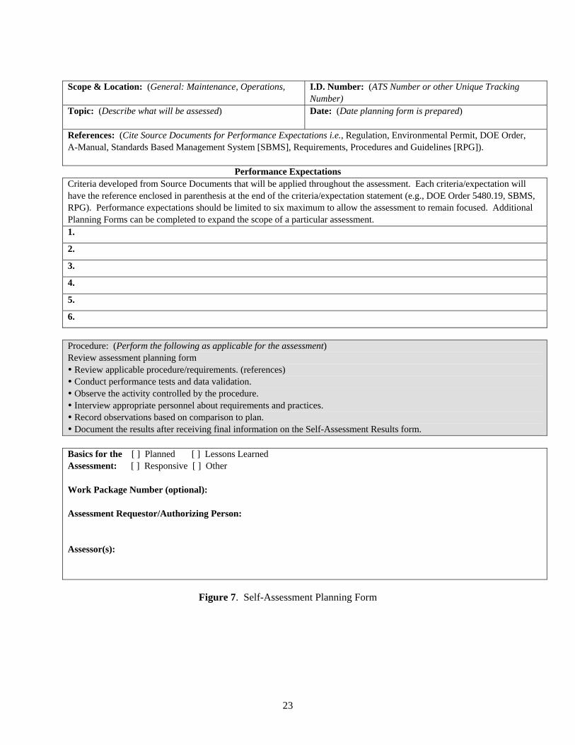
Assessment planning is done by the project management team (including Project Manager, Task Leaders, and appropriate project staff) in consultation with the project Quality Engineer. An assessment schedule will be developed by the project Quality Engineer with Project Manager approval. Assessments may be accomplished by the project staff, project management, and/or the Quality Engineer in accordance with the SBMS subject area, Planning, Assessment, and Analysis, Section 2 Performance Assessment (PNNL 2005c). The assessor plans the assessment by completing a Self-Assessment Planning Form where the scope of the assessment, topic and supporting references are documented on the plan. A unique identification number is assigned to the plan and entered on an Assessment Log Sheet. The Task Manager approves the plan. Figure 7 shows the form that should be used for self-assessment planning.
23
Scope & Location: (General: Maintenance, Operations,
I.D. Number: (ATS Number or other Unique Tracking Number)
Topic: (Describe what will be assessed)
Date: (Date planning form is prepared)
References: (Cite Source Documents for Performance Expectations i.e., Regulation, Environmental Permit, DOE Order, A-Manual, Standards Based Management System [SBMS], Requirements, Procedures and Guidelines [RPG]).
Performance Expectations Criteria developed from Source Documents that will be applied throughout the assessment. Each criteria/expectation will have the reference enclosed in parenthesis at the end of the criteria/expectation statement (e.g., DOE Order 5480.19, SBMS, RPG). Performance expectations should be limited to six maximum to allow the assessment to remain focused. Additional Planning Forms can be completed to expand the scope of a particular assessment. 1.
2.
3.
4.
5.
6.
Procedure: (Perform the following as applicable for the assessment) Review assessment planning form Review applicable procedure/requirements. (references) Conduct performance tests and data validation. Observe the activity controlled by the procedure. Interview appropriate personnel about requirements and practices. Record observations based on comparison to plan. Document the results after receiving final information on the Self-Assessment Results form.
Basics for the [ ] Planned [ ] Lessons Learned Assessment: [ ] Responsive [ ] Other Work Package Number (optional): Assessment Requestor/Authorizing Person: Assessor(s):
Figure 7. Self-Assessment Planning Form

24
Documentation of assessments will be documented on a Self-Assessment Results form (see Figure 8). The corrective action and action owner will be documented on the assessment report. The action owners will be assigned by the Task Manager. An action item log will be maintained by the project Quality Engineer to track and close out actions. The Project Manager will prioritize the corrective actions. The corrective actions will be verified by the project Quality Engineer. When the corrective actions have been closed, the Project Manager will sign the assessment report. The assessment plan and report will distributed to the appropriate Task Managers, Project Manager and project records. Assessor:
I.D. Number:
Assessment Location:
Date: (Date assessment performed)
Results (Related to Associated Performance Expectations)
(Use additional pages if necessary.) Concise and objective statements are the goal. Subjective comments may be added at the end and must be based upon a series of facts that supports the comments. Include strengths and improvement opportunities. Include date the information is obtained and list of line manager or points-of-contact during assessment. Summary 1.
2.
3.
4.
5.
Subsequent Actions (Related to Associated Results)
Assigned Action Action Owner Due Date
1.
2.
3.
4.
Actions Assigned By: Date:
Completion (To be signed by Lead Assessor when assessment is completed.) Signature: Date: Completion (To be signed by Manager when assessment is completed and all actions have been entered into ATS) Signature: Date:
Figure 8. Self-Assessment Results

25
8.2 Subcontractor Assessments
Periodic assessments of the analytical subcontractors are performed as an oversight function or prior to contract award in accordance with the internal acquisition quality procedures. Provisions are made in the SOW to subcontractors for oversight assessment activities to be performed as necessary.
The results of all analytical subcontractors’ assessments (including surveillances and audits) will be made available to project and line management, individuals contacted, and the client as requested. The corrective action tracking, corrective action and closure response will be in accordance with the internal acquisition quality procedures. The official assessment report files and responses (audits and surveil-lances) are maintained in the PNNL Suppliers History File by the Quality Assurance Services group.
Surveillances of the sampling subcontractor activities will be performed by the project Quality Engi-neer in accordance with the internal acquisition quality procedures. A fiscal year surveillance schedule will be developed by the project Quality Engineer and approved by the Sampling Subtask Leader. The results will be documented in a source verification report and a copy of the report is provided to the sampling subcontractor in accordance with the internal acquisition quality procedures. Also, the original report will be maintained in the PNNL Suppliers History File. A corrective action will be supplied by the sampling subcontractor and approved by the project Quality Engineer. The corrective action will be verified by a follow-up surveillance. The corrective action response letter, the corrective action accep-tance letter, and the final closure letter will be maintained in the PNNL Supplier History File. The corrective action will be tracked by the project Quality Engineer.
Periodic assessments of the well drilling and construction, geophysical logging, gyroscope well deviation survey’s activities, and the ESL may also be performed in accordance with the requirements discussed above.
9.0 Preventive Equipment Maintenance
Subcontracted organizations will be required to implement preventive maintenance on their equipment to mitigate the possibility of down time affecting cost and schedule. This will be specified in the SOW to the respective organizations.
10.0 Specific Routine Procedures Used to Assess Data Precision, Accuracy, and Completeness
The evaluation of laboratory precision, accuracy, and completeness is accomplished during the verification process performed by the Data Processing Sub-Task at PNNL upon receipt of data (see Section 7 of this plan).

26
11.0 Corrective Action
11.1 Project Corrective Actions Resulting from Assessments
As part of the continuous improvement processes initiated by the project management team, assessments will be tracked and improvement actions identified and prioritized. If immediate corrective action is required, the quality problem will be directly entered into the Assessment Tracking System (ATS) and resultant corrective action as specified in Section 11.2.
11.2 Unplanned Deviations
Corrective action must be initiated by the Project Manager or cognizant Task Leader when unplanned deviations from procedural, contractual, regulatory requirements, or construction specifications occur. These deviations will be documented by documenting the quality problem information directly into the ATS in accordance with SBMS subject area, Quality Problem Reporting (PNNL 2005d). The assessment must describe the problem, the cause of the deviation, the impact of the problem, and corrective action needed to remedy the immediate problem and to prevent recurrence.
Subcontractors will be required to have a system in place to identify, correct and prevent recurrence of contractual, procedural or regulatory requirement(s) deviations and to notify the PNNL point-of-contact specified when such an event occurs. These requirements will be passed on in a SOW to the subcontractors.
11.3 Planned Deviations
Planned deviations from procedure, documented (including justification) and approved by the Project Manager or Task Leader in advance, do not constitute a deficiency and do not require generation of an assessment item. Documentation may consist of a hard copy e-mail or memo to the Project Manager or Task Leader. This documentation must include either an approval signature if on a memo or electronic approval via a reply to the e-mail indicating such approval.
11.4 Measuring and Test Equipment Calibration Discrepancies
Subcontractors will be required to maintain a system for identifying calibration discrepancies and tracing data or samples that may have been affected. Subcontractors will be required, via a SOW, to notify the PNNL point-of-contact as soon as possible when such an incident occurs. PNNL will perform periodic assessments to assess the effectiveness of subcontractor procedures and processes for calibration control.
Project staff must investigate instruments or equipment found to be operating outside acceptable operating ranges (as specified in the applicable technical procedure or manufacturer’s instructions) and issues must be addressed in accordance with SBMS subject area Quality Problems Reporting (PNNL 2005d). When it is determined from calibration verification that Category 1 or 2 Measuring and Test Equipment is out of tolerance, proceed with the evaluation to determine impact on data and document the results with justification.

27
12.0 Quality Assurance Reports to Management
Quality activities, such as project improvement efforts, significant deficiencies identified and corrective actions, and summary of assessment results of project activities will be reported to the Project Manager. When major quality problems are identified, they shall be reported to the Project Manager. Surveillance plans and results of the surveillances are provided to the Project Manager and Task Manager monthly or after a surveillance event. QC results are provided to the Project Manager and Groundwater Monitoring Task Manager every quarter.
Quality-related problems identified by project personnel must be reported to project management immediately for resolution. Any problems involving data quality, sample integrity, or test measurements will be thoroughly documented by a RDR and/or a Problem and Discrepancies form and communicated to the appropriate Task Leader and Project Manager for resolution.
Monthly and quarterly reports are provided to DOE that summarize accomplishments, describe the cost and schedule status, the sampling and analysis status, and variances. An annual groundwater monitoring report is generated reporting the groundwater monitoring results to the client, regulatory agencies, Tribal Nations, and the public. A quarterly report summarizing the results of sampling, analysis, and data evaluation in support of RCRA monitoring is provided to DOE for transmittal to the regulatory agencies.
Significant quality-related problems that may affect customer satisfaction shall be communicated to the Product Line Manager by the Project Manager.
13.0 Records
13.1 Records Control
Records that document the sampling subcontractor activities, analytical results, verification and compliance checks, quarterly and annual reports, test plans and associated results, groundwater monitoring plans, and assessment reports will be maintained as project records. Individual monitoring plans and work plans may identify other records requirements. Project records will be legible, identifiable and maintained in accordance with PNNL SBMS subject area Records Management (PNNL 2005e).
The Project Records Specialist prepares and submits a Records Inventory and Disposition Schedule (RIDS) File Index for review and approval by the records management representative and Quality Engineer. The records custodian reviews and updates the RIDS annually at a minimum, or major change to the program. Records retention schedules shall be based on requirements of TPA (Ecology et al. 1989), which requires the retention of records for 10 years after termination of the TPA.

28
13.2 Records Transfer to Storage
On an annual basis, the records custodian will transfer to storage inactive records as identified by the Task/Subtask Manager that are not required for day-to-day operations. Sampling and analysis plans, assessments, and special project correspondences as identified by the Task/Subtask Manager will be maintained by the project until the completion of the activity or project. The PNNL project staff member originating the transfer should complete the appropriate internal form (e.g., Records Transfer/Data Input (RTDI) form). The records management representative will sign the RTDI form as acknowledging receipt of the records and return a copy of this form to the records custodian. The RTDI form is then placed in project records.
Within 90 days of project completion or termination, records shall be transferred to storage and/or the client.
14.0 Procurement Control
For this project, the majority of procurements will result in purchases of services such as analytical, sampling, support to hydrologic testing, and geophysical logging of boreholes. All procurements will be obtained in accordance with SBMS subject area, Purchasing Goods and Services (PNNL 2006). SOWs for purchasing services shall be reviewed and signed by the project Quality Engineer to assure consis-tency of quality assurance requirements specified to subcontractors with project quality standards in this plan.
14.1 Groundwater Sampling
Purchase orders (POs) shall be used to obtain sample collection and water level measurements. An electronic requisition will be prepared by project staff accompanied by a work authorization document (letter of Instruction (LOI) or SOW). The work authorization document will include requirements for sample collection, sample handling, sample labeling, custody of the samples in the field to delivery to the analytical laboratory or shipper, and water level measurements. The SOW will pass on the requirements of the EPA Requirements for Quality Assurance Project Plans (EPA/240/B-01/003, QA/R-5) and HASQARD to the subcontractor. A review must be performed by the Quality Engineer during the planning stages and preparation of the SOW/LOI.
14.2 Groundwater Analytical Services
Work package authorizations (WPAs), work orders (WOs), or POs, as applicable, shall be used to obtain analytical services. A letter of instruction or SOW must accompany each WO, WP, or PO. A review must be performed by the Quality Engineer during the planning stages and preparation of the SOW/LOI. The work authorization document must define the data quality and any additional project requirements associated with the service requested. The data quality requirements should include a description of the QC samples for each analysis for determining the level of possible contamination from preparation and analysis. The project requirements should include information on analysis method, calibration standards traceable to the National Institute of Standards and Technology, sample turnaround

29
time and reporting requirements, and disposal requirements for remaining sample material and the waste from the process. The SOW will pass on the requirements of the EPA Requirements for Quality Assurance Project Plans (EPA-600/R-02/009, QA/R-5) and HASQARD to the subcontractor.
14.3 Other Hanford Contractor Services
Other Hanford contractor services (e.g., well drilling and construction, geophysical logging) will be obtained using the procurement process. An electronic requisition will be generated by project staff accompanied by a work authorization document (LOI or SOW). The work authorization document will describe the requirements for the requested services. The SOW will pass on the requirements of the EPA Requirements for Quality Assurance Project Plans (EPA-600/R-02/009, QA/R-5) and HASQARD to the subcontractor. A review must be performed by the Quality Engineer during the planning stages and preparation of the SOW/LOI.
14.4 Sediment Analytical Services
Analytical services will be procured by using a work authorization document (LOI or SOW) accompanied by a WPA or WO. A review must be performed by the Quality Engineer during the planning stages and preparation of the SOW/LOI. The work authorization document must define the data quality and any additional project requirements associated with the service requested. The data quality requirements should include a description of the QC samples for each analysis for determining the level of possible contamination from preparation and analysis. The project requirements should include information on analysis method, calibration standards traceable to the National Institute of Standards and Technology, sample turnaround time and reporting requirements, and disposal requirements for remaining sample material and the waste from the process. The SOW will pass on the requirements of the EPA Requirements for Quality Assurance Project Plans (EPA-600/R-02/009, QA/R-5) and HASQARD to the subcontractor.
15.0 Staff Training
Staff performing activities affecting quality shall be issued documented training assignments including applicable project administrative and technical procedures and this plan.
1. Task Leaders and staff members will assess project specific training needs. The assessment will include evaluating cumulative training records of the staff.
2. Task Leaders will assign reading /or briefings of procedures as needed. If training is assessed and the need for formalized training identified, the staff member will be scheduled to attend a formal training class.
3. Task Leaders and staff will document training on a Briefing Document, an individual On-the-Job Training (OJT) or Reading Assignment Documentation form, or a Group OJT or Reading Assign-ment Documentation form. These forms are available internally to PNNL staff. Documentation shall be sent to the PNNL Laboratory Training Coordinator for input into the training database. The training database will contain the record copy of project staff training.

30
Subcontractors are responsible for special training of their staff in accordance with the respective SOW.
16.0 Software Control
Various tasks of the project require the use of databases and software, which are managed, controlled, and operated by entities that are outside PNNL. The project also requires the use of databases and software that are developed, managed, controlled and operated by PNNL. A graded approach is used to establish software quality assurance requirements based on identified risk. Software QA at PNNL is now based on DOE Order 414.1C (Quality Assurance). This order establishes specific requirements for software related to safety and nuclear facilities. As part of the continuous improvement process, the project will develop a software management plan that describes the project approach in meeting the software quality assurance requirements.
FHI is responsible for the management, operation, and maintenance of HEIS (including SDT tables) and HWIS. However, PNNL is responsible for the integrity, accuracy, and traceability of the data that PNNL collects.
The project has developed and uses databases, custom applications, and configurable software to support various business processes including but not limited to development of sample scheduling and collection, data tracking, data verification and loading and reporting (see Section 6.2). These databases, custom applications, and configurable software (spreadsheets, and queries) used to generate reportable results shall be documented in accordance with the SBMS subject area, Software (PNNL 2005f). This documentation is maintained in project files.
17.0 Nonconformances and Deficiencies
For procured materials found to be in nonconformance with specifications or where the quality of an activity found not to be in compliance, the quality problem will be documented into the ATS in accor-dance with the SBMS subject area, Quality Problems Reporting (PNNL 2005d). Corrective actions are documented by using ATS in accordance with the SBMS subject area, Assessment Management (PNNL 2005a).
If a deficiency is found where a procedure or process is not followed or the activity is not in compli-ance with a procedure or process, the deficiency will be documented into the ATS in accordance with the SBMS subject area, Quality Problems Reporting (PNNL 2005d). Corrective action will be documented using ATS in accordance with the SBMS subject area, Assessment Management (PNNL 2005a).
When the analytical data (hard copy or electronic data) is found to be incomplete or deficient in data by the data processing staff verification, a Problem and Discrepancies form is filled out in accordance with the PNNL internal procedure DM-3, Verification of Analytical Data. Also, when the technical staff

31
performs the initial data review and/or a comparison of the recent data to historical trends, any suspect data is submitted to the verification group by a RDR.
Subcontractors will be required to have a system for identifying and dispositioning nonconforming items, procedure deficiencies, process not followed, or activities not in compliance to a procedure or a process. This requirement will be specified in a SOW.
18.0 Document Control
18.1 Project QA Plan Control
Distribution and control of this QA Plan shall be performed in accordance with SBMS subject area Publishing Scientific and Technical Information (PNNL 2002). Modifications to this plan shall be made either by revision or by issuing an Interim Change Notice (ICN). See Figure 9 for the ICN form and instructions. This plan will be revised after four ICNs or a major change in project scope or requirements from DOE. Any PNNL staff member may request a change to this QA Plan at any time by submitting the requested change in writing to the Project Manager and Quality Engineer. All reviewers listed on the signature page and affected by the change will approve the revision. The ICN will be placed in front of the signature page and the individual pages will be placed or the necessary correction will be lined out and correction added with initial and date. The QA Plan will be reviewed at least every 2 years.
18.2 Technical Procedure Control
Technical procedures referenced by this QA Plan and used by PNNL staff will be contained in an PNNL internal procedure manual, Procedures for Ground-Water Investigations. Technical procedures will be distributed and controlled in accordance with SBMS subject area, Document Control (PNNL 2001). Modifications to any of the internal procedures shall be made either by revision or by issue of an ICN. There are minor or major changes and their definitions are described in Section 18.1. Figure 9 shows the form and instructions.
Procedures will be revised after two major ICNs, or if the procedure format has changed. Any PNNL staff member may request a change to procedures at any time by submitting the requested change in writing to the author, Sampling and Analyses Task Manager, and Quality Engineer. The author, technical reviewer, groundwater project Task Manager, and project Quality Engineer will review and approve the ICN. The ICN will be placed in front of the signature page and the individual pages will be placed or the necessary correction will be lined out and correction added with initial and date. Contact the Project Quality Engineer for the electronic copy of the ICN. New or revised technical procedures, whether they will be included in the internal procedures manual or not, must be developed in accordance with SBMS subject area, Procedures, Permits, and Other Work Instructions (PNNL 2004). The procedure owner is required to review the procedure at least every 3 years.

32
INSTRUCTIONS FOR ICN FORM HEADER: The ICN number is identified as ICN No.-____. For a published groundwater monitoring plan, each page of the ICN shall have a header on the right upper
corner that includes the report number, the date and the pagination. The number of the ICN must be placed after the PNNL number. The second line of the header should show the date and pagination. The cover sheet needs to identify how many pages in the ICN packet.
Example header: PNNL-xxxxx-ICN-x Month, day, year; Page x of xx SECTION A.
Self-explanatory. SECTION B.
Include all actions that the document holder must take to update the procedure or instruction. Possible actions include: replacing pages of the document with pages that are distributed with the ICN and marking up the document (in ink) to reflect the changes identified on the ICN or attach the ICN cover sheet to the front of the document.
For a “Published” groundwater monitoring plan include the following statement: “Attach this ICN to the front of the document, just before the title page.”
SECTION C.
Identify, by title, all personnel whose job functions will be affected by the change and include a brief description of the effect. If there is no effect on personnel (e.g., the change was made to clarify the intent of the procedure or to correct a typographical error) this block should be marked “N/A.”
SECTION D.
State the reason for the change followed by a description of the change (including the affected paragraph, information which is deleted, and the actual wording of any replacement test) for each change included on the ICN.
SECTION E.
The Cognizant Manager shall document the reason for not obtaining original reviewers approval and/or any other decisions that must be documented. Additionally, list the individuals who will receive the document (distribution list).
SECTION F.
Identify type of change and document required approvals.
Figure 9. Interim Change Notice

33
INTERIM CHANGE NOTICE (ICN)
Page ___ of ___ A. Document No.: Revision No.: Document Title: Document’s Original Author:
Implementation Date of ICN: / /
Change Requested By:
B. Action:
C. Effect of Change:
D. Reason for Change/Description of Change: Reason for Change: Description of Change:
E. Document Management Decisions:
F. Groundwater Monitoring Task Manager Approval Signatures (Please Sign and Date)
Project Quality Engineer Approval: _____________________________________________________________Date: __________________________ Author Approval: _____________________________________________________________________________Date: __________________________ Other Approvals: _____________________________________________________________________________Date: __________________________
Figure 9. (contd)

34
18.3 Administrative Procedure /Instruction Preparation and Control
Administrative procedures/instructions used by PNNL staff will be developed, approved, and controlled to ensure consistent application by those staff performing the defined task(s). These procedures/instructions will be developed, approved, and controlled in a manner that has been approved by appropriate project management and Quality Engineer.
18.4 Groundwater Monitoring Plans
Distribution and control of RCRA groundwater monitoring plans shall be performed in accordance with SBMS subject area Publishing Scientific and Technical Information (PNNL 2002). Different types of monitoring plans have different document change control requirements, as discussed in the following sections. Change control will include internal as well as external (e.g., DOE) requirements.
18.4.1 RCRA Interim-Status Plans
These plans are PNNL documents and are released through ERICA. Modifications to these plans shall be made using an ICN or by revising the plan. (Figure 9 shows the ICN form and instructions.) The number of ICNs that may be written for a single plan is not limited so long as revision control is maintained and the working version of the plan and ICN is not in question. Distribution and control of the ICN shall be through ERICA. The author, Groundwater Monitoring Task Manager, and the project Quality Engineer will review and approve the ICN.
Project change control for these plans in the interim period between ICNs or revisions is maintained by the sampling and analysis change request process. These changes are approved by project manage-ment, attached to the current plan in project records, and implemented via the project scheduling system.
18.4.2 RCRA Final-Status Plans
Final-status plans may be stand-alone documents that are cited in the Hanford Facility RCRA Permit (Ecology 1994), or contained in the Permit itself. Final-status monitoring plans are revised through the Permit Modification process, which is described in the TPA (Ecology et al. 1989) and in the Hanford Facility RCRA Permit (Ecology 1994). Depending on the magnitude (or class) of the changes, they will require contractor and DOE review and approval, regulatory agency review and approval, and/or public review and participation.
18.4.3 CERCLA Sampling and Analysis Plans
Monitoring plans supporting CERCLA groundwater operable units are referred to specifically as sampling and analysis plans (SAPs) and are released as DOE documents. Distribution and control of these plans shall be performed in accordance with SBMS subject area Publishing Scientific and Technical Information (PNNL 2002). The SAPs are reviewed and, if necessary, revised annually; this requires DOE and regulatory agency review and approval. The SAPs may have temporary (duration less than one year) additions (adding constituents, wells, or increasing frequency), or unavoidable changes (such as dry wells, missed or delayed samples); these require notification to project management and DOE, as well as
35
notification to the regulatory agency via email messages or Unit Manager Meeting minutes. Permanent changes (for duration more than one year) are identified to DOE and regulatory agencies for approval prior to documenting them in the revised SAPs. Distribution and control of the revised SAPs shall be by the project editor.
Project change control in the interim period between SAP revisions is maintained by the Sampling and Analysis Change Request process. These changes are approved by project management, attached to the current plan in project records, and implemented via the project scheduling system.
Waste Control Plans and Waste Management Plans also support CERCLA groundwater operable unit activities, and are released as DOE documents. These plans may be revised as needed, based on changes in the activities occurring within the respective operable unit. These plans may have changes made to the well tables (e.g., new wells) that are documented by submitting the revised page(s) to the Unit Manager Meeting minutes. These page revisions are placed with the original plan in the associated operable unit RIDS category of the project records.
18.4.4 Other Monitoring Plans
Other monitoring plans may include plans for AEA monitoring (e.g., 100-K Basins). These plans are PNNL documents and distribution and control of these plans shall be performed in accordance with SBMS subject area Publishing Scientific and Technical Information (PNNL 2002b). Modifications to these plans shall be made using an ICN or by revising the plan, as discussed in Section 18.4.1.
Project change control for the plans in the interim period between ICNs or revisions is maintained by the Sampling and Analysis Change Request process. These changes are approved by project manage-ment, attached to the current plan in project records, and implemented via the project scheduling system.
19.0 References
10 CFR 830. U.S. Department of Energy. “Energy/Nuclear Safety Management, Subpart A--Quality Assurance Requirements.” U.S. Code of Federal Regulations.
40 CFR 136, Chapter 1, Appendix B (7/1/01). U.S. Environmental Protection Agency. “Guidelines Establishing Test Procedures for the Analysis of Pollutants.” U.S. Code of Federal Regulations.
40 CFR 264. U.S. Environmental Protection Agency. “Standards for Owners and Operators of Hazardous Waste Treatment, Storage, and Disposal Facilities.” U.S. Code of Federal Regulations.
40 CFR 265. U.S. Environmental Protection Agency. “Interim Status Standards for Owners and Operators of Hazardous Waste Treatment, Storage, and Disposal Facilities.” U.S. Code of Federal Regulations.
40 CFR 300. U.S. Environmental Protection Agency. “National Oil and Hazardous Substances Pollution Contingency Plan.” U.S. Code of Federal Regulations.

36
Atomic Energy Act. 1954, as amended, Ch. 1073, 68 Stat. 919, 42 USC 2011 et seq.
CERCLA – Comprehensive Environmental Response, Compensation, and Liability Act. 1980. Public Law 96-150, as amended, 94 Stat. 2767, 42 USC 9601 et seq.
DOE Order 414.1C. 2005. Quality Assurance. U.S. Department of Energy, Washington, D.C.
DOE Order 435.1. 2001. Radioactive Waste Management. U.S. Department of Energy, Washington, D.C.
DOE Order 450.1. 2003. Environmental Protection Program. U.S. Department of Energy, Washington, D.C.
DOE Order 5480.19. 1990, as amended. Conduct of Operations Requirements for DOE Facilities. U.S. Department of Energy, Washington, D.C.
DOE/RL-96-68. 1998. Hanford Analytical Services Quality Assurance Requirements Documents. HASQARD, Volumes 1, 2, 3, and 4. U.S. Department of Energy, Richland Operations Office, Richland, Washington.
Ecology - Washington State Department of Ecology, U.S. Environmental Protection Agency, and U.S. Department of Energy. 1989, as amended. Hanford Federal Facility Agreement and Consent Order. Document No. 89-10 (The Tri-Party Agreement), Olympia, Washington.
Ecology. 1994. Dangerous Waste Portion of the Resource Conservation and Recovery Act Permit for the Treatment, Storage, and Disposal of Dangerous Waste. Permit Number WA7890008967, as amended. Washington State Department of Ecology, Olympia, Washington.
EMSL-LV-0539-17. 1979. Radiochemical Analytical Procedures for Analysis of Environmental Samples. U.S. Environmental Protection Agency, Las Vegas, Nevada.
EPA/240/B-01/003 (QA/R-5). 2001. EPA Requirements for Quality Assurance Project Plans. U.S. Environmental Protection Agency, Washington, D.C.
EPA/240/B-06/001 (QA/G-4). 2006. Guidance on Systematic Planning Using the Data Quality Objectives Process. U.S. Environmental Protection Agency, Washington, D.C.
EPA-600/4-79/019. 1979. Handbook for Analytical Quality Control in Water and Wastewater Laboratories. U.S. Environmental Protection Agency, Cincinnati, Ohio.
EPA-600/4-79-020. 1983. Methods for Chemical Analysis of Water and Wastes. U.S. Environmental Protection Agency, Washington, D.C.
EPA-600/4-80-032. 1980. Prescribed Procedures for Measurement of Radioactivity in Drinking Water. U.S. Environmental Protection Agency, Cincinnati, Ohio.
EPA-600/4-88-039. 1988. Methods for the Determination of Organic Compounds in Drinking Water. U.S. Environmental Protection Agency, Washington, D.C.

37
EPA-R4-73-014. 1973. Procedures for Radiochemical Analysis of Nuclear Reactor Aqueous Solutions. U.S. Environmental Protection Agency, Cincinnati, Ohio.
EPA/SW-846. 1980, as amended. Test Methods for Evaluating Solid Waste: Physical/Chemical Methods, SW-846, Third Edition. Office of Solid Waste and Emergency Response, U.S. Environmental Protection Agency, Washington, D.C. Available online at http://www.epa.gov/epaoswer/hazwaste/test/main.htm
National Water Well Association. 1986. RCRA Ground Water Monitoring Technical Enforcement Guidance Document. Dublin, Ohio.
RCRA – Resource Conservation and Recovery Act. 1976. Public Law 94-580, as amended, 90 Stat. 2795, 42 USC 6901 et seq.
PNNL. 2002. Publishing Scientific and Technical Information. Standards-Based Management System, Pacific Northwest National Laboratory, Richland, Washington. Available online at https://sbms.pnl.gov/standard/80/8000t010.htm
PNNL. 2004. Procedures, Permits, and Other Work Instructions. Standards-Based Management System, Pacific Northwest National Laboratory, Richland, Washington. Available online at https://sbms.pnl.gov/standard/74/7400t010.htm
PNNL. 2005a. Assessment Management. Standards-Based Management System, Pacific Northwest National Laboratory, Richland, Washington. Available online at http://sbms.pnl.gov/standard/4i/4i00t010.htm
PNNL. 2005b. Calibration. Standards-Based Management System, Pacific Northwest National Laboratory, Richland, Washington. Available online at https://sbms.pnl.gov/standard/79/7906d010.htm
PNNL. 2005c. Planning Assessment, and Analysis. Standards-Based Management System, Pacific Northwest National Laboratory, Richland, Washington. Available online at http://sbms.pnl.gov/standard/18/1800t010.htm
PNNL. 2005d. Quality Problems Reporting. Standards-Based Management System, Pacific Northwest National Laboratory, Richland, Washington. Available online at http://sbms.pnl.gov/standard/78/7800t010.htm
PNNL. 2005e. Records Management. Standards-Based Management System, Pacific Northwest National Laboratory, Richland, Washington. Available online at http://sbms.pnl.gov/standard/1a/1a00t010.htm
PNNL. 2005f. Software. Standards-Based Management System, Pacific Northwest National Laboratory, Richland, Washington. Available online at http://sbms.pnl.gov/standard/94/9400t010.htm
PNNL. 2006. Purchasing Goods and Services. Standards-Based Management System, Pacific Northwest National Laboratory, Richland, Washington. Available online at https://sbms.pnl.gov/standard/3i/3i00i010.htm
38
U.S. Geological Survey. 1977. National Handbook of Recommended Methods for Water Data Acquisition. Office of Water Data Coordination. Reston, Virginia.
WAC 173-160. “Minimum Standards for Construction and Maintenance of Wells.” Washington Administrative Code, Olympia, Washington.
WAC 173-216. “State Waste Discharge Program.” Washington Administrative Code, Olympia, Washington.
WAC 173-303. “Dangerous Waste Regulations.” Washington Administrative Code, Olympia, Washington.
WAC 173-303-645(11)(g). “Dangerous Waste Regulations; Releases from Regulated Units.” Washington Administrative Code, Olympia, Washington.
WAC 173-304. Minimum Functional Standards for Solid Waste Handling. Washington Administrative Code, Olympia, Washington.

Appendix
Groundwater Performance Assessment Project Quality Control Plan

A.1
Appendix
Groundwater Performance Assessment Project Quality Control Plan
A.1 Introduction
This appendix describes the basic methods and procedures to implement a groundwater monitoring quality control task for sampling and analysis conducted in association with the Groundwater Perform-ance Assessment Project. The quality control (QC) practices described in this plan help to evaluate whether samples free of contamination are obtained during sampling and that the laboratory performed sample analyses within the accuracy and precision limits required by the project.
Most of the information in this appendix applies only to groundwater samplers. Quality control practices and requirements that pertain to soil and sediment samples are described in Section A.5.
The primary objectives of this plan are listed below:
1. Identify the QC elements selected for the Groundwater Performance Assessment Project. 2. Provide data quality objectives (DQO) for reporting limits, precision, accuracy, and completeness. 3. Indicate actions that are to be taken for out of tolerance data.
Data quality needs for certain Resource Conservation and Recovery Act (RCRA) facilities may be more stringent that the QC criteria defined in this plan. DQOs for those units are defined in the groundwater monitoring plans specific to those sites.
A.2 Technical Requirements
The technical requirements for QC are divided into two types – components that provide checks on field and laboratory activities (Field QC) and factors that help to monitor laboratory performance (Laboratory QC). Each type of QC sample has required frequencies and acceptance criteria.
The following guidance documents were used as aids in determining the QC elements necessary for the Groundwater Performance Assessment Project:
1. Quality Assurance Manual for the Waste Management Branch Investigations (EPA 910/9-86-00).
2. Resource Conservation and Recovery Act (RCRA) Groundwater Monitoring Technical Enforcement Guidance Document (EPA/OSWER-9950.1).
3. Test Methods for Evaluating Solid Waste: Physical/Chemical Methods, SW-846, Third Edition (EPA/SW-846).
4. Handbook for Analytical Quality Control in Water and Wastewater Laboratories (EPA-600/4-79-019).
5. Hanford Analytical Services Quality Assurance Requirements Documents (HASQARD) (DOE/RL-96-68).

A.2
QC elements were selected based on the needs of the project and the value the results from each type of sample will add to the data. A.2.1 Field Quality Control
To indicate whether groundwater samples are collected in a consistent manner and are properly preserved and transported to the analytical laboratory, four types of QC samples are collected before or during sampling:
1. Full Trip Blanks (FTB) — These samples are prepared by the sampling team before traveling to a sampling site. A preserved bottle set, identical to the set that will be used for sample collection in the field, is filled with reagent water (carbon free, deionized water). Dead water from well 699-S11-E12AP is used for low-level tritium FTBs. The FTB bottles are sealed by the sampling team and transported unopened to the field in the same storage container that will be used for the samples collected that day. These samples are typically analyzed for the same constituents as the samples from the associated well.
2. Field Transfer Blanks (FXR) — Preserved volatile organic analysis (VOA) sample bottles are filled at the sample collection site with reagent water that has been transported to the field. The samples are prepared during the sampling of a well to evaluate potential contamination caused by conditions in the field. After collection, the FXR bottles are sealed and placed in the same sample storage container as the rest of the samples. The FXR bottles are not removed from the storage container until delivery to the analytical laboratory. FXR samples are typically analyzed for volatile organic compounds (VOC) only.
3. Equipment Blanks (EB) —Reagent water is passed through the pump or manifold after decontam-ination (sometimes just prior to sampling) to collect blank samples identical to a set that will be collected in the field. Preserved bottles are used. The EB bottles are placed in the same container as the associated field samples. EB samples are not removed from the container until delivery to the analytical laboratory.
4. Field Duplicates (DUP) — A replicate sample that is collected at one well. After each type of bottle is filled, a second, identical bottle is filled for each type of analysis as directed by chain-of-custody requirements. Both sets of samples are stored and transported together.
Using several types of field blank samples provides checks on bottle cleanliness, preservative purity, equipment decontamination, proper storage and transport of samples, and reveals whether or not samples collected for volatiles may have been contaminated during collection. Sampling in replicate provides information about sampling reproducibility. Field QC sample frequencies are shown in Table A.1. In addition to the evaluation characteristics described in Table A.1, the field QC samples also provide a check on the analytical laboratory. The field QC data are designed to give an overall impression of the performance of the sampling and analysis of the Groundwater Performance Assessment Project; however, individual data points associated with field QC samples that are outside of the acceptance criteria are flagged in the HEIS database.

A.3
Table A.1. Quality Control Samples
Field QC Sample Type Primary Characteristics Evaluated Frequency
Full Trip Blank (FTB) Contamination from containers or transportation
1 per 20 well trips
Field Transfer Blank (FXR) Contamination from sampling site 1 each day VOCs sampled Equipment Blank (EB) Contamination from non-dedicated
equipment As needed(a)
Replicate/Duplicate Samples
Reproducibility 1 per 20 well trips
Laboratory QC Sample Type Primary Characteristics Evaluated Frequency
Method Blanks Laboratory Contamination 1 per batch Lab Duplicates Laboratory Reproducibility (b)
Matrix Spikes Matrix Effect and Laboratory Accuracy (b)
Matrix Spike Duplicates Laboratory Reproducibility/Accuracy (b)
Surrogates Recovery/Yield (b)
Laboratory Control Samples Method Accuracy 1 per batch
(a) For portable Grundfos pumps, equipment blanks are collected one per ten well trips. Whenever a new type of non-dedicated equipment is used, an equipment blank shall be collected every time sampling occurs until it can be shown that less frequent collection of equipment blanks is adequate to monitor the decontamination procedure for the non-dedicated equipment.
(b) As defined in the laboratory contract or QA plan and/or analysis procedures. QA = Quality assurance. QC = Quality control. VOC = Volatile organic compound.
The results of each type of field QC sample are evaluated according to criteria defined in Table A.2.

A.4
Table A.2. Field and Laboratory QC Elements and Acceptance Criteria
Method(a) QC Element Acceptance Criteria Corrective Action
General Chemical Parameters Alkalinity - EPA 600 Series, 310.1 MB(b) < MDL Flagged with “C” Chemical Oxygen Demand - EPA 600 Series, 410.4 LCS 80-120% recovery(c) Data reviewed(d)
Conductivity - EPA 600 Series, 120.1 DUP ± 20% RPD(c) Data reviewed(d) Oil and Grease - EPA 600 Series, 413.1 MS(e) 75-125% recovery(c) Flagged with “N” pH - EPA 600 Series, 150.1 EB, FTB < 2X MDL Flagged with “Q” Total Dissolved Solids - EPA 600 Series, 160.1 Field Duplicate ± 20% RPD(f) Flagged with “Q” Total Organic Carbon - SW-846, 9060 Total Organic Halides - SW-846, 9020
Ammonia and Anions Ammonia - EPA 600 Series, 350.1 MB < MDL Flagged with “C” Anions by IC - EPA 600 Series, 300.0 LCS 80-120% recovery(c) Data reviewed(d) Cyanide - SW-846, 9012 DUP ± 20% RPD(c) Data reviewed(d) MS 75-125% recovery(c) Flagged with “N” EB, FTB < 2X MDL Flagged with “Q” Field Duplicate ± 20% RPD(f) Flagged with “Q”
Metals Arsenic - SW-846, 7060 MB < CRDL Flagged with “C” Cadmium - SW-846, 7131 LCS 80-120% recovery(c) Data reviewed(d) Chromium - SW-846, 7191 MS 75-125% recovery(c) Flagged with “N” Lead - SW-846, 7421 MSD ± 20% RPD(c) Data reviewed(d) Mercury - SW-846, 7470 EB, FTB < 2X MDL Flagged with “Q” Selenium - SW-846, 7740 Field Duplicate ± 20% RPD(f) Flagged with “Q” Thallium - SW-846, 7841 ICP Metals - SW-846, 6010 ICP/MS Metals - SW-846, 6020
Volatile Organic Compounds Volatiles by GC/MS - SW-846, 8260 MB < MDL Flagged with “B” Total Petroleum Hydrocarbons by GC LCS Statistically derived(g) Data reviewed MS Statistically derived(g) Flagged with “N” MSD Statistically derived(g) Data reviewed(d) SUR Statistically derived(g) Data reviewed(d) EB, FTB, FXR < 2X MDL(h) Flagged with “Q” Field Duplicate ± 20% RPD(f) Flagged with “Q”
Semivolatile Organic Compounds Herbicides by GC - SW-846, 8151 MB < 2X MDL Flagged with “B” PCBs by GC - SW-846, 8082 LCS Statistically derived(g) Data reviewed(d) Pesticides by GC - SW-846, 8081 MS Statistically derived(g) Flagged with “N” Phenols by GC - SW-846, 8041 MSD Statistically derived(g) Data reviewed(d) Semivolatiles by GC/MS - SW-846, 8270 SUR Statistically derived(g) Data reviewed(d) EB, FTB < 2X MDL(h) Flagged with “Q” Field Duplicate ± 20% RPD(f) Flagged with “Q”

A.5
Table A.2. (contd)
Method QC Element Acceptance Criteria Corrective Action
Radiological Parameters Gamma Scan MB < 2X MDA Flagged with “B” Gross Alpha - SW-846, 9310 LCS 70-130% recovery Data reviewed(c) Gross Beta - SW-846, 9310 DUP ± 20% RPD Data reviewed(c) Iodine-129 MS(i) 60-140% recovery Flagged with “N” Plutonium (isotopic) EB, FTB < 2X MDA Flagged with “Q” Strontium-89/90 Field
Duplicate ± 20% RPD(e) Flagged with “Q”
Technetium-99 Tritium - SW-846, 906.0 Tritium (low-level) Uranium (isotopic) Uranium (total)
(a) EPA/SW-846, as amended. (b) Does not apply to pH. (c) Laboratory-determined, statistically derived control limits may also be used. Such limits are reported
with the data. (d) After review, corrective actions are determined on a case-by-case basis. Corrective actions may include
a laboratory recheck or flagging the data as suspect (Y flag) or rejected (R flag). (e) Applies to total organic carbon and total organic halides only. (f) Applies only in cases where one or both results are greater than 5X the detection limit. (g) Determined by the laboratory based on historical data. Control limits are reported with the data. (h) For common laboratory contaminants such as acetone, methylene chloride, 2-butanone, toluene, and
phthalate esters, the acceptance criteria is < 5X MDL. (i) Applies only to technetium-99 and total uranium analyses. Data Flags: B, C = Possible laboratory contamination (analyte was detected in the associated method blank). N = result may be biased (associated matrix spike result was outside the acceptance limits). Q = problem with associated field QC sample (blank and/or duplicate results were out of limits). DUP = Laboratory matrix duplicate. EB = Equipment blank. FTB = Full trip blank. FXR = Field transfer blank. GC = Gas chromatography. ICP = Inductively coupled plasma. ICP/MS = Inductively coupled plasma-mass spectrometry. LCS = Laboratory control sample. MB = Method blank. MDA = Minimum detectable activity. MDL = Method detection limit. MS = Matrix spike. MSD = Matrix spike duplicate. PCBs = Polychlorinated biphenyls. RPD = Relative percent difference. SUR = Surrogate.

A.6
Bias is assessed by comparing a measured value to a known or accepted reference value or the recovery of a known amount of spiked contaminant into a sample (i.e., a matrix spike). For a matrix spike (MS) bias caused by matrix effects is calculated as follows:
B = (Xs – Xu) – K
where X = measured value of spiked sample Xu = sample or miscellaneous contribution K = known value of spike
Using the following equation yields percent recovery (%R):
%R = 100 (Xs - Xu)/ K
Analytical precision is determined by analyzing duplicates (field or lab). Precision is expressed as either percent relative standard deviation (RSD) or relative percent difference (RPD). Duplicate results are flagged if the results of both samples are quantifiable (i.e., the result is greater than the 5 times the instrument detection limit [IDL]/method detection limit [MDL]/minimum detectable activity [MDA]) and the RPD is greater than 20%. The RPD is calculated as follows:
100 x 2/)D (D
D - D RPD
21
21
+=
where D1 = original sample value D2 = duplicate sample value
When more than two data values are present, calculate precision by the RSD:
RSD = standard deviation x 100 mean
A.2.2 Quality Control in the Laboratory
The ability of the laboratories to perform sample analyses within the limits established by the project is monitored in several ways. Internal quality assurance programs are maintained by laboratories utilized by the Groundwater Performance Assessment Project. In addition, the laboratories are periodically reviewed and audited both internally and externally. PNNL participates in external audits. Laboratory quality assurance includes a comprehensive quality control program, which includes the use of matrix spikes (MS), matrix duplicates (MD), matrix spike duplicates (MSD), laboratory control samples (LCS), surrogates, tracers, and blanks. These samples are recommended in the guidance documents and are required by U.S. Environmental Protection Agency (EPA) protocol.
Matrix Duplicate (MD) — An intra-laboratory split sample that is used to evaluate the precision of a method in a given sample matrix.
Matrix Spike (MS) — An aliquot of a sample spiked with a known concentration of target analyte(s). The MS is used to assess the bias of a method in a given sample matrix. Spiking occurs prior to sample preparation and analysis.

A.7
Matrix Spike Duplicate (MSD) — A replicate spiked aliquot of a sample that is subjected to the entire sample preparation and analytical process. MSD results are used to determine the bias and precision of a method in a given sample matrix.
Laboratory Control Sample (LCS) — A control matrix spike (e.g., deionized water) spiked with analytes representative of the target analytes or a certified reference material that is used to evaluate laboratory accuracy.
Method Blank — An analyte-free matrix to which all reagents are added in the same volumes or proportions as used in sample processing. The method blank is carried through the complete sample preparations and analytical procedure. The method blank is used to quantify contamination resulting from the analytical process.
Surrogates — A compound added to all samples in the analysis batch (field samples and QC samples) prior to preparation. The surrogate is typically similar in chemical composition to the compound or analyte being determined, yet not normally encountered in most samples. Surrogates are expected to respond to the preparation and measurement systems in a manner similar to the analytes of interest. Because surrogates are added to all standards, samples, and QC samples, they are a useful tool in evaluating overall method performance in a given matrix. Surrogates are utilized only in organic analyses.
Tracers — A tracer is a known quantity of radioactive isotope that is different from that of the isotope of interest but is expected to behave similarly and is added to an aliquot of sample. Sample results are generally corrected based on tracer recovery.
The laboratories are required to analyze samples within the holding times specified by the analysis procedure. In some instances, constituents in samples not analyzed within the holding time may be compromised by volatilization, decomposition or other chemical changes. Data from samples analyzed outside the holding time are flagged in the HEIS database with an H. The holding times for constituents frequently analyzed by the Groundwater Performance Assessment Project are listed in Table A.3.
Other tools are used by the project to evaluate the laboratories. Double-blind standards of the constituents of concern are submitted to the primary laboratory in triplicate or quadruplicate on a quarterly basis. Because the results of double-blind standards provide information on laboratory precision and accuracy, these standards are useful tools to verify that the project DQOs is being met. Table A.4 lists the typical blind-standard constituents and their submission frequencies. Due to the occasional need to investigate potential problems at the laboratories, the list of constituents is subject to change. Specific information about the constituents used and their spiking levels will be maintained in the project files.

A.8
Table A.3. Groundwater Performance Assessment Project Holding Times
Constituents Methods Holding Times
Volatile organics SW-846,(a) 8010/8020/8260 14 days Semivolatile organics SW-846, 8270 7 days before extraction
40 days after extraction Pesticides SW-846, 8080 7 days before extraction
40 days after extraction Polychlorinated biphenyls SW-846, 8080 7 days before extraction
40 days after extraction Chlorinated herbicides SW-846, 8150 7 days before extraction
40 days after extraction Phenols SW-846, 8040 7 days before extraction
40 days after extraction ICP metals SW-846, 6010 6 months ICP-MS SW-846, 6020 6 months Arsenic SW-846, 7060 6 months Lead SW-846, 7421 6 months Mercury SW-846, 7470/7471 28 days Selenium SW-846, 7740 6 months Thallium SW-846, 7841 6 months Alkalinity EPA 600 Series, 310.1 14 days Cyanide SW-846, 9010/9012 14 days Bromide EPA 600 Series, 300.0 28 days Chloride EPA 600 Series, 300.0 28 days Fluoride EPA 600 Series, 300.0 28 days Nitrate EPA 600 Series, 300.0 48 hours Nitrite EPA 600 Series, 300.0 48 hours Phosphate EPA 600 Series, 300.0 48 hours Sulfate EPA 600 Series, 300.0 28 days Total organic carbon SW-846, 9060 28 days Total organic halides SW-846, 9020 28 days Chemical oxygen demand EPA 600 Series, 410.4 28 days _______________ (a) EPA/SW-846, as amended.

A.9
Table A.4. Blind-Standard Constituents and Schedule
Constituents Frequency Recommended Recovery
(%)(a) Precision (%RSD)(a)
Carbon Tetrachloride Quarterly ±25 % ±25 % Chloroform Quarterly ±25 % ±25 % Trichloroethylene Quarterly ±25 % ±25 % Fluoride Quarterly ±25 % ±25 % Nitrate Quarterly ±25 % ±25 % Cyanide Quarterly ±25 % ±25 % Chromium Annually ±20 % ±20 % Total Organic Carbon(b) Quarterly Varies according to
spiking compound Varies according to spiking compound
Total Organic Halides(c) Quarterly Varies according to spiking compound
Varies according to spiking compound
Gross alpha(d) Quarterly 70 - 130 % ±20 % Gross beta(e) Quarterly 70 - 130 % ±20 % Tritium Annually 70 – 130 % ±20 % Tritium (low level) Semi-annual 70 – 130 % ±20 % Cobalt-60 Annually 70 – 130 % ±20 % Strontium-90 Quarterly 70 – 130 % ±20 % Technetium-99 Quarterly 70 – 130 % ±20 % Iodine-129 Semi-
annually 70 – 130 % ±20 %
Cesium-137 Annually 70 – 130 % ±20 % Uranium Quarterly 70 – 130 % ±20 % Plutonium-239/240 Quarterly 70 – 130 % ±20 % (a) If the results are less than 5 times the required detection limit, then the criteria is that the difference of
the results of the replicates is less than the required detection limit. (b) The spiking compound generally used for total organic carbon (TOC) is potassium phthalate. Other
spiking compounds may also be used. (c) Two sets of spikes for total organic halides (TOX) will be used. The spiking compound for one set
should be 2,4,5-trichlorophenol. The spiking compound for the second set should include the constituents used for the volatile organic compounds (VOC) sample (carbon tetrachloride, chloroform, trichloroethylene).
(d) The gross alpha sample will be prepared from Pu-239. (e) The gross beta sample will be prepared from Sr-90. RSD = Relative standard deviation.
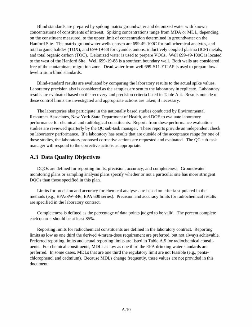
A.10
Blind standards are prepared by spiking matrix groundwater and deionized water with known concentrations of constituents of interest. Spiking concentrations range from MDA or MDL, depending on the constituent measured, to the upper limit of concentration determined in groundwater on the Hanford Site. The matrix groundwater wells chosen are 699-49-100C for radiochemical analytes, and total organic halides (TOX); and 699-19-88 for cyanide, anions, inductively coupled plasma (ICP) metals, and total organic carbon (TOC). Deionized water is used to prepare VOCs. Well 699-49-100C is located to the west of the Hanford Site. Well 699-19-88 is a southern boundary well. Both wells are considered free of the contaminant migration zone. Dead water from well 699-S11-E12AP is used to prepare low-level tritium blind standards.
Blind-standard results are evaluated by comparing the laboratory results to the actual spike values. Laboratory precision also is considered as the samples are sent to the laboratory in replicate. Laboratory results are evaluated based on the recovery and precision criteria listed in Table A.4. Results outside of these control limits are investigated and appropriate actions are taken, if necessary.
The laboratories also participate in the nationally based studies conducted by Environmental Resources Associates, New York State Department of Health, and DOE to evaluate laboratory performance for chemical and radiological constituents. Reports from these performance evaluation studies are reviewed quarterly by the QC sub-task manager. These reports provide an independent check on laboratory performance. If a laboratory has results that are outside of the acceptance range for one of these studies, the laboratory proposed corrective actions are requested and evaluated. The QC sub-task manager will respond to the corrective actions as appropriate.
A.3 Data Quality Objectives
DQOs are defined for reporting limits, precision, accuracy, and completeness. Groundwater monitoring plans or sampling analysis plans specify whether or not a particular site has more stringent DQOs than those specified in this plan.
Limits for precision and accuracy for chemical analyses are based on criteria stipulated in the methods (e.g., EPA/SW-846, EPA 600 series). Precision and accuracy limits for radiochemical results are specified in the laboratory contract.
Completeness is defined as the percentage of data points judged to be valid. The percent complete each quarter should be at least 85%.
Reporting limits for radiochemical constituents are defined in the laboratory contract. Reporting limits as low as one third the derived 4-mrem-dose requirement are preferred, but not always achievable. Preferred reporting limits and actual reporting limits are listed in Table A.5 for radiochemical constit-uents. For chemical constituents, MDLs as low as one third the EPA drinking water standards are preferred. In some cases, MDLs that are one third the regulatory limit are not feasible (e.g., penta-chlorophenol and cadmium). Because MDLs change frequently, these values are not provided in this document.

A.11
Table A.5. Reporting Limits for Radiochemical Constituents
Constituent of Concern Method CAS # DWS 1/3 DWS RDL
Gross Alpha Gross Alpha - GA 12587-46-1 15 pCi/L* 5 pCi/L* 3 pCi/L Gross Beta Gross Beta - GB 12587-47-2 N/A N/A 4 pCi/L Cobalt-60 Gamma Spec 10198-40-0 100 pCi/L 33 pCi/L 25 pCi/L Cesium-137 10045-97-3 200 pCi/L 67 pCi/L 15 pCi/L Europium-152 50 pCi/L Europium-154 200 pCi/L 67 pCi/L 50 pCi/L Europium-155 600 pCi/L 200 pCi/L 50 pCi/L Tritium H-3 10028-17-8 20,000 pCi/L 6700 pCi/L 400 pCi/L Tritium H-3 (LL) N/A N/A N/A 10 pCi/L Iodine-129 I-129 10043-66-0 1 pCi/L 0.33 pCi/L 5 pCi/L Iodine-129 I-129 (LL) N/A N/A N/A 1 pCi/L Strontium-90 Sr-89/Sr-90 10098-97-2 8 pCi/L 2.7 pCi/L 2 pCi/L Technetium-99 Tc-99 14133-76-7 900 pCi/L 300 pCi/L 15 pCi/L Plutonium-238 Isotopic Plutonium 1.6 pCi/L 0.5 pCi/L 1 pCi/L Plutonium-239/240 Pu-AEA 1.2 pCi/l 0.4 pCi/L 1 pCi/L Uranium-234 Isotopic Uranium 13966-29-5 20 pCi/L 6.7 pCi/L 1 pCi/L Uranium-235 Uranium-AEA 15117-96-1 24 pCi/L 8 pCi/L 1 pCi/L Uranium-238 U-238 24 pCi/L 8 pCi/L 1 pCi/L Total alpha energy emitted from Radium
Total Radium N/A N/A N/A 1 pCi/L
Uranium (elemental)
Total Uranium N/A 30 μg/L 10 μg/L 0.1 μg/L
* Excluding uranium CAS# = Chemical abstract service number. DWS = Drinking water standard. N/A = Not applicable. RDL = Required detection limit.
A.4 Reporting and Deliverables Requirements
The results of the blind standards and the field QC samples will be provided through current analytical reporting procedures. The QC analytical results will be reviewed by the QC sub-task manager and compiled in a database for statistical analysis and trending.
Compiled QC data will be submitted annually for the Hanford Site groundwater monitoring report (e.g., PNNL-15670).

A.12
A.4.1 Quarterly Progress Reports
Previous quarter results will be provided to the Groundwater Performance Assessment Project staff for review and assessment. The schedule for each quarterly report is determined by the reporting sub-task manager.
A.4.2 Washington State Department of Health
The Washington State Department of Health (DOH) is responsible for verifying the adequacy and accuracy of environmental radiation monitoring programs in Washington. As part of this oversight, DOH requests that the Groundwater Performance Assessment Project split well and blind spike samples with the DOH laboratory at regular intervals throughout the year. The results from these split samples are summarized in the Washington State Environmental Radiation Program Annual Reports (e.g., DOH 1990). This arrangement helps to assure that the commercial laboratories used for radiochemical analysis of Hanford groundwater samples are performing satisfactorily.
A.4.3 Project Records
All project records associated with quality control are maintained in accordance with the RIDS for the Groundwater Performance Assessment Project.
A.5 Requirements for Soil and Sediment Samples
Occasionally, the Groundwater Performance Assessment Project may have soil or sediment samples analyzed in support of site-characterization activities. The non-routine nature of this work precludes specification of many of the requirements listed previously for groundwater samples. Therefore, the types, quantities, and acceptance criteria for field and/or laboratory QC samples are specified in monitoring plans and/or the laboratory statement of work. Table A.6 lists the maximum recommended holding times for common analytes in soils. Radionuclides are not included in the table.
Table A.6. Holding Times for Soil and Sediment Analyses
Constituents Methods Holding Times
Volatile organics SW-846,(a) 8260 14 days Semivolatile organics SW-846, 8270 14 days before extraction
40 days after extraction Pesticides SW-846, 8080 14 days before extraction
40 days after extraction Polychlorinated biphenyls SW-846, 8080 14 days before extraction
40 days after extraction Chlorinated herbicides SW-846, 8150 14 days before extraction
40 days after extraction Phenols SW-846, 8040 14 days before extraction
40 days after extraction ICP metals SW-846, 6010 6 months ICP-MS SW-846, 6020 6 months

A.13
Arsenic SW-846, 7060 6 months Lead SW-846, 7421 6 months Mercury SW-846, 7470/7471 28 days Selenium SW-846, 7740 6 months Thallium SW-846, 7841 6 months Alkalinity EPA 600 Series, 310.1 14 days Cyanide SW-846, 9010/9012 14 days Bromide EPA 600 Series, 300.0 28 days Chloride EPA 600 Series, 300.0 28 days Fluoride EPA 600 Series, 300.0 28 days Nitrate EPA 600 Series, 300.0 48 hours Nitrite EPA 600 Series, 300.0 48 hours Phosphate EPA 600 Series, 300.0 48 hours Sulfate EPA 600 Series, 300.0 28 days Total organic carbon SW-846, 9060 28 days Total organic halides SW-846, 9020 28 days Chemical oxygen demand EPA 600 Series, 410.4 28 days _______________ (a) EPA/SW-846, as amended.
A.6 References
DOE/RL-96-68. 1998. Hanford Analytical Services Quality Assurance Requirements Documents. (HASQARD), Volumes 1 through 4, U.S. Department of Energy, Richland, Washington.
DOH. 1990. Washington State Environmental Radiation Program Annual Report. Washington State Department of Health, Olympia, Washington
EPA-600/4-79-019. 1979. Handbook for Analytical Quality Control in Water and Wastewater Laboratories. U.S. Environmental Protection Agency, Cincinnati, Ohio.
EPA 910/9-86-00. 1986. Quality Assurance Manual for Waste Management Branch Investigations. U.S. Environmental Protection Agency, Region 10, Seattle, Washington.
EPA/OWSER-9950.1. 1986. Resource Conservation and Recovery Act (RCRA) Groundwater Monitoring Technical Enforcement Guidance Document. U.S. Environmental Protection Agency, Washington, D.C.
EPA/SW-846. 1986, as amended. Test Methods for Evaluating Solid Waste: Physical/Chemical Methods, SW-846, Third Edition. Office of Solid Waste and Emergency Response, U.S. Environmental Protection Agency, Washington, D.C. Available online at http://www.epa.gov/epaoswer/hazwaste/test/sw846.htm

A.14
PNNL-145670. 2006. Hanford Site Groundwater Monitoring for Fiscal Year 2005. MJ Hartman, LF Morasch, and WD Webber (eds.), Pacific Northwest National Laboratory, Richland, Washington.
PNNL-15014, Rev. 1
Distr.1
Distribution No. of Copies ONSITE 2 DOE Richland Operations Office * DOE Public Reading Room (2) H2-53 43 Pacific Northwest National Laboratory D. B. Barnett K6-81 L. R. Burns K6-94 J. S. Carr K6-96 C. J. Chou K6-81 S. F. Conley K6-75 P. E. Dresel K6-96 D. Felmy K6-96 J. S. Fruchter K6-96 H. Hampt K6-96 M. J. Hartman K6-96 D. G. Horton K6-81 E. A. Lepel P8-01 J. W. Lindberg K6-81 S. P. Luttrell K6-96 J. P. McDonald K6-96
No. of Copies A. V. Mitroshkov K6-96 L. F. Morasch K8-86 S. M. Narbutovskih K6-96 T. G. Naymik K6-96 C. A. Newbill K6-96 D. R. Newcomer K6-96 R. E. Peterson K6-96 S. P. Reidel K6-81 J. T. Rieger K6-96 R. Schalla K6-96 D. S. Sklarew K6-96 R. M. Smith K6-96 F. A. Spane K6-96 D. L. Stewart K6-96 M. D. Sweeney K6-81 C. J. Thompson K6-96 E. C. Thornton K6-96 * K. Waters-Husted (Project Files) K6-96 T. G. Walker P7-87 W. D. Webber K6-96 B. A. Williams K6-81 * Hanford Technical Library (2) P8-55
*Received printed hard copies. All others received electronic distribution.