the gorham building
TRANSCRIPT
The Gorham Building
Instructions for Assembly ofThe Gorham Building
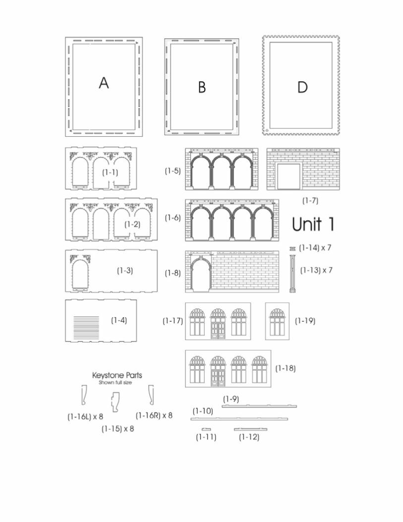
Kit Contents: 163 each laser cut acrylic parts, 8each sidewalk parts, 5 each Window Templates, 5each Window Glazing, Instructions with diagrams.
Thank you for purchasing this kit. Please read theseinstructions completely before beginning and takeyour time. Allow parts to dry after painting orgluing and do not try to build this in one night.
Drawings of all the parts have been included forease of part identification.
Practice gluing the acrylic together if you havenever done it before. There is plenty of scrap inyour kit that you can use for this.
If by chance a part is missing or broken, pleasewrite us indicating the kit name and part number and we will send you a replacement.
You will need the following items to assemble your model: Sharp hobby knife, file, paint (see“Painting Your Model”), paint brushes, glue (see “Gluing Acrylic”), modeling putty.
About the Kit
This kit will build a eight story building. The kit is built up in modules labeled as units. There arefour units in all. The units range from 2 to 4 stories. The units stack on top of each other whencompleted.
The assembly of each unit is very similar. Once you have built the first unit you will most likelybe able to build the rest without reading the instructions. However... I spent a lot of time writingthe instructions so I would appreciate it if you would. Repetitive sequences will be described indetail the first time and then less so subsequently.
Parts are labeled in the instructions inside parentheses. The first number is the unit number andthe second is the part number in that unit. For instance (3-6) would be part six in unit three.Each unit has a base and top that are identified with a letter. As these are the same for multipleunits there is no unit number associated with these.
Many parts have engraved details on them. Be sure that these are facing out when gluing theparts together. It is easy to install these backwards by mistake.
Gluing Acrylic
Always glue acrylic in a well-ventilated area, and read the glue manufacturer’s label forinstructions.
We recommend using Tenax-7R by Hebco or Plastruct brand “Plastic Weld Solvent Cement”(PPC-2 or PPC-16) or “Bondine Solvent Cement”(Bond-2 or BOND-16). Tenax-7R comes witha dispenser and Plastruct sells a Solvent Syringe (HT-8 or HT-10) and various other solventdispensers. Most hobby shops carry these products or they may be ordered directly from Hebco(931)-796-7442 or Plastruct (626)-912-7016.
Acrylic must be glued together using a solvent that will melt the two edges and literally fusethem together. To do this, place the two pieces to be joined together and run a bead of solventdown the edge. Capillary action will suck the solvent into the joint and after several seconds thepieces will be fused. After only a few minutes the pieces will be strong enough to work with. Thebond will be completely dry within twenty-four hours using the above-mentioned products.Solvent can be dispensed two ways.
Typically the solvent comes in a small bottle with a brush in the lid. The brush allows you todispense a drop or two of solvent at a time.
You may want to use a polyethylene bottle or syringe with a blunt needle dispenser. This allowslarger amounts of solvent to be dispensed quickly and cleanly. Be sure the bottle you are using isapproved for the solvent you are using or you may melt through it. These may be purchased fromCMR.
Preparing Your Model for Painting
We recommend lightly sanding all parts to remove the raised edge created during the lasercutting process. In order to hide the seams we recommend using “hobbyist putty” such as GreenSquadron modeling putty. Do this in a very well-ventilated area. Apply the putty over the seamsand allow to dry overnight. Once the putty has dried, place a sheet of fine sandpaper on a flatsurface and sand smooth. You may need to apply a second coat of putty and sand again.
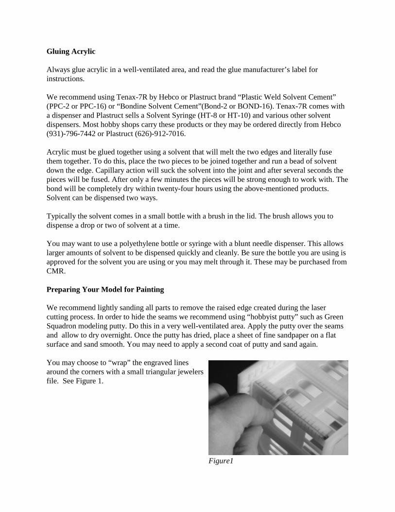
You may choose to “wrap” the engraved linesaround the corners with a small triangular jewelersfile. See Figure 1.
Figure1

Painting Your Model
After building each unit and prior to installing the windows we primed our building with KrylonGray spray paint. We also primed the window frames. For our building paint scheme, we used“Poly Scale Acrylic” paints which are available in most hobby stores. We also used “Poly ScaleAcrylics” for details and weathering. Always test compatibility of your paint with the acrylic bypainting and testing a small area first.
Alcohol can cause acrylic to crack and “shatter”. Do not use alcohol to clean the parts or alcoholbased pints. If you apply washes to your building we recommend using a water based wash.
If you plan to light your buildings interior than we recommend that you prime the building insideand out. This will prevent the walls from glowing.
We painted the building white and the windows black. We then made a beige wash with “PolyScale” paints. The building units were laid flat with a wall facing up and the wash was appliedand allowed to dry. The unit was then rotated to the next wall and the process was repeated, andso on. We air brushed the back and alley walls with a dirty black mix so that they would bedarker. Finally we installed the painted windows into the units.
Note on Tabs
Sometimes it is necessary to sand or file the tabs slightly in order to get them to seat themselvesinto the slots. This is due to slight variations in acrylic thickness. If the tabs are not fitting intothe slots properly, you may need to file them back at an angle to fit properly.
Window Glass
There are printed window shades included with your kit. These are designed to be laminated withacetate window glazing prior to installing in your model. The printed window shades arenumbered to correspond with the window frame parts.
Lightly spray glue the window shade pages on theprinted side with spray mount and apply a sheet ofacetate to them. Press in place. We used 3M SprayMount part number 6065 which is available at craftand office supply stores. Glue these to the back ofthe window frames using super glue (CA) after youhave painted them as noted in the instructions.
After gluing the window glazing to the windowframes, place the assembly face up on a cuttingmatt and trim off any excess glazing with a hobbyknife. See figure 2.
Figure 2

Assembling the Tower Units
This structure is asymmetrical in that opposite sides do not match one another in detail andcharacter. There are two detailed sides, or street sides, which have engraving and multiple layersbuilt-up to create depth. The shorter of these sides will be referred to as the front, and the longeras the side. The two remaining sides are lessdecorative and have fewer windows. The shorter ofthese sides will be referred to as the back, and thelonger as the alley. Figure 3 shows base part Aface up with the first set of wall parts ready toinstall into their appropriate places.
Please note that all pieces referred to as bases andtops (parts A, B, C, etc.) should have the partnumber facing up during assembly unlessotherwise noted. This is the correct orientation toinsure that the tabs on the wall parts will fit intothe slots facing the right direction.
Wall and Window Orientation
The tabs on the wall parts are symmetrical, and we recommend assembling the walls the way wehave shown. You may choose to flip the side and alley sides, however, if the windowarrangement works better for you. Just be sure to be consistent with this and flip your windowframes as well.
Unit 1
Begin by taking base (A) and laying it flat on your work surface with the engraved part numberfacing up. Insert the tabs of the “front” wall (1-1) into the slots on a short side of part (A) andglue in place (see figure 3 for orientation). Note that the tabs on the top and bottom of the wallparts are different sizes and positions, and the walls will only fit into part (A) in one direction.
Working clockwise, insert the tabs of the “side”wall (1-2) into the slots on the long side of part(A) and glue in place. The two walls should meetand be glued at the corner. Insert the tabs of the“back” wall (1-3) into the slots on the remainingshort side of part (A) and glue in place. Then,insert the tabs of the alley wall (1-4) into the slotson the last side of part (A) and glue in place toform a box. Make sure to glue all the cornerstogether. See Figure 4.
Figure 3
Figure 4

Glue the top (B) onto the assembly with theengraved part number facing up. Check that all the tabs are seated properly. See Figure 5.
Now that the basic wall structure is together, thewalls get built out. When gluing the next piecesinto place, take care to note that all the cornersshould be flush and that the engraved sides arefacing out. This will save you time from having tofile overhangs or fill gaps.
Parts (1-5) through (1-8) form the second layer and will be affixed to the surface of theirrespective walls, using the window placement asyour guide. Parts (1-6) and (1-8) are adhered first.The windows should be centered and the sideedges flush with the first layer. If you have anyoverhang, file flat before installing the two othersides. Parts (1-5) and (1-7) are adhered last.See Figures 6,7 & 8.
Fill and sand the corners of the assembly ifnecessary. You may choose to “wrap” theengraved lines around the corners with a smalltriangular jewelers file. See “Preparing your Model for Painting”.
Figure 5
Figure 6
Figure 7 Figure 8

Cornice parts are installed in the slots on the second layer of walls. Working clockwise, part (1-9) is glued to the front wall, part (1-10) is glued to the side wall, part (1-11) is glued to theback wall, and part (1-12) is glued to the alley wall. See Figures 9 &10.
Next, decorative columns, parts (1-13), are glued tothe corners and one wall. These will be placedunder the cornice that you just installed and at thevery edge of each corner around the entire unit. Aseventh column should be affixed to the alley sideto the right of the window opening. See Figure 11
Small columns, parts (1-14), are glued to unit 1above the cornice parts, and directly above parts(1-13) See Figures 12 & 13.
Figure 9 Figure 10
Figure 11
Figure 13Figure 12

The keystone above each arched window is madeup of three parts. Part (1-15) is the center of thekeystone. Parts (1-16L) and (1-16R) form thesides. Insert and glue the tab of part (1-15) into theslot above each window arch of unit 1. The rightangle that forms the top and back of the keystoneshould be flush with the small cornice trim and thewall. Note that the back of these parts will have aslight angle due to how the acrylic is cut. Do notlet the piece tilt when attaching. Attach part(1-16L) to the left side of part (1-15), and part(1-16R) to the right side of part (1-15). Again, theright angle of the top and back should be flush. We recommend finishing each keystone beforemoving on to the next one. This will help insurethat parts (1-15) do not tilt before adhering thesides. You should have eight keystones total,although the kit includes some extra pieces. See Figures 14 & 15.
Attach part D to the top of the unit using the centeropenings as your placement guide.See Figure 16.
Paint the unit and set aside to dry. Once dry, applythe wash and hand paint the garage door on theback side your choice of color. We also chose topaint the arches and keystones a lighter gray to addcontrast.
Paint the window frames (1-17), (1-18), and (1-19)your choice of color and install the window glazingas described earlier. When gluing the windowframes in the building, make certain that theengraved side is facing out. Install part (1-17)behind the “front” wall, part (1-18) behind the“side” wall, and part (1-19) behind the “alley”wall. See Figure 17.
Figure 14
Figure 15
Figure 16
Figure 17

Unit 2
Begin by taking base © and laying it flat on yourwork surface with the engraved part number facingup. Insert the tabs of the “front” wall (2-1) into theslots on a short side of part © and glue in place. Working clockwise, insert the tabs of the “side”wall (2-2) into the slots on the long side of part ©and glue in place. The two walls should meet andbe glued at the corner. Insert the tabs of the “back”wall (2-3) into the slots on the remaining short sideof part © and glue in place. Then, insert the tabs ofthe alley wall (2-4) into the slots on the last side ofpart © and glue in place to form a box. Make sureto glue all the corners together. Glue the top (B)onto the assembly with the engraved part numberfacing up. Check that all the tabs are seatedproperly. See Figure 18.
Fill and sand the corners of the assembly ifnecessary. You may choose to “wrap” theengraved lines around the corners with a smalltriangular jewelers file. See “Preparing your Modelfor Painting”.
Next, decorative columns are glued to the cornersand one wall. These are made of 2 overlappingparts. Begin by affixing the stone strips parts (2-5)to the corners of the side and alley walls. Theseparts should be flush with the edges of the walls. Then, glue parts (2-5) to the corner of the front andback walls. These parts should overlap the sides ofthe respective parts on the longer walls. Last, onestone strip is glued to the alley wall between theengraved lines where there is no stone pattern. This will be directly above the column from unit 1to the right of the window. See Figure 19.
The column parts (2-6) are now adhered to thestone strips parts (2-5). When affixing these, theyshould be glued to the edge of the corner formedby parts (2-5), but not overlapping one another. See Figure 20.
Figure 18
Figure 19
Figure 20

Attach part D to the top of the unit using the centercut-outs as your placement guide.
Paint the unit and set aside to dry. Once dry, applythe wash.
Paint the window frames (2-7), (2-8), (2-9), and(2-10) your choice of color and install the windowglazing as described earlier. Install part (2-7)behind the “front” wall, part (2-8) behind the“side” wall, part (2-9) behind the “back” wall, and(2-10) behind the “alley” wall. See Figure 21.
Unit 3
Begin by taking base © and laying it flat on your work surface with the engraved part numberfacing up. Insert the tabs of the “front” wall (3-1) into the slots on a short side of part © and gluein place. Working clockwise, insert the tabs of the “side” wall (3-2) into the slots on the longside of part © and glue in place. The two wallsshould meet and be glued at the corner. Insert thetabs of the “back” wall (3-3) into the slots on theremaining short side of part © and glue in place.Then, insert the tabs of the alley wall (3-4) into theslots on the last side of part © and glue in place toform a box. Make sure to glue all the cornerstogether. Glue the top (B) onto the assembly withthe engraved part number facing up. Check that allthe tabs are seated properly. See Figure 22.
Now that the basic wall structure is together, thewalls get built out. When gluing the next piecesinto place, take care to note that all the corners should be flush and that the engraved sides arefacing out. This will save you time from having to file overhangs or fill gaps.
Figure 21
Figure 22

Parts (3-5) through (3-8) form the second layer and will be affixed to the surface of theirrespective walls, using the window placement as your guide. Parts (3-6) and (3-8) are adheredfirst. The windows should be centered and the side edges flush with the first layer. If you haveany overhang file flat before installing the two other sides. Parts (3-5) and (3-7) are adhered last. Make sure that part (3-7) is oriented correctly to match the thickness top and bottom of the othersides. See Figures 23 & 24.
Next, decorative columns, parts (3-9), are glued tothe corners and one wall. These will be placed atthe very edge of each corner around the entire unit. A seventh column should be affixed to the alleyside to the right of the 2 window openings withgrills. This will be directly above the columnsfrom units 1 and 2. See Figure 25.
Attach part D to the top of the unit using the centercut-outs as your placement guide
Paint the unit and set aside to dry. Once dry, applythe wash. We also chose to hand paint thegrillwork dark gray and the columns a lighter grayto add contrast.
Paint the window frames (3-10), (3-11), (3-12),and (3-13) your choice of color and install thewindow glazing as described earlier. Install part(3-10) behind the “front” wall, part (3-11) behindthe “side” wall, part (3-12) behind the “back” wall,and (3-13) behind the “alley” wall. See Figure 26.
Figure 24Figure 23
Figure 25
Figure 26
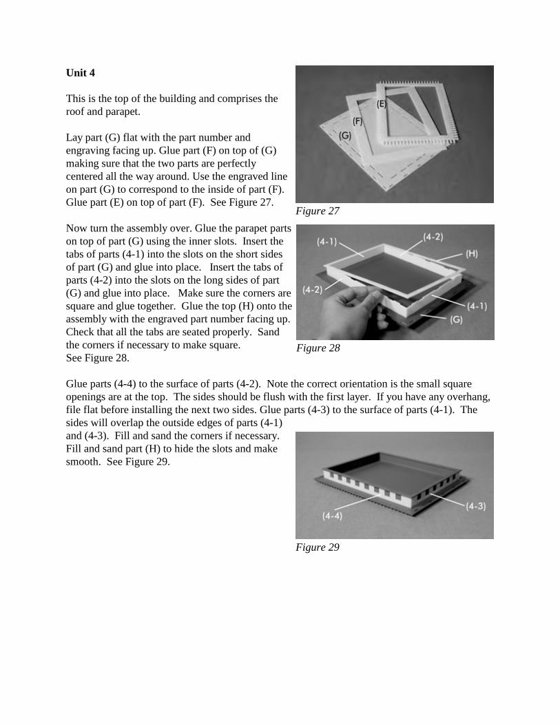
Unit 4
This is the top of the building and comprises theroof and parapet.
Lay part (G) flat with the part number andengraving facing up. Glue part (F) on top of (G)making sure that the two parts are perfectlycentered all the way around. Use the engraved lineon part (G) to correspond to the inside of part (F). Glue part (E) on top of part (F). See Figure 27.
Now turn the assembly over. Glue the parapet partson top of part (G) using the inner slots. Insert thetabs of parts (4-1) into the slots on the short sidesof part (G) and glue into place. Insert the tabs ofparts (4-2) into the slots on the long sides of part(G) and glue into place. Make sure the corners aresquare and glue together. Glue the top (H) onto theassembly with the engraved part number facing up.Check that all the tabs are seated properly. Sandthe corners if necessary to make square.See Figure 28.
Glue parts (4-4) to the surface of parts (4-2). Note the correct orientation is the small squareopenings are at the top. The sides should be flush with the first layer. If you have any overhang,file flat before installing the next two sides. Glue parts (4-3) to the surface of parts (4-1). Thesides will overlap the outside edges of parts (4-1)and (4-3). Fill and sand the corners if necessary. Fill and sand part (H) to hide the slots and makesmooth. See Figure 29.
Figure 27
Figure 28
Figure 29
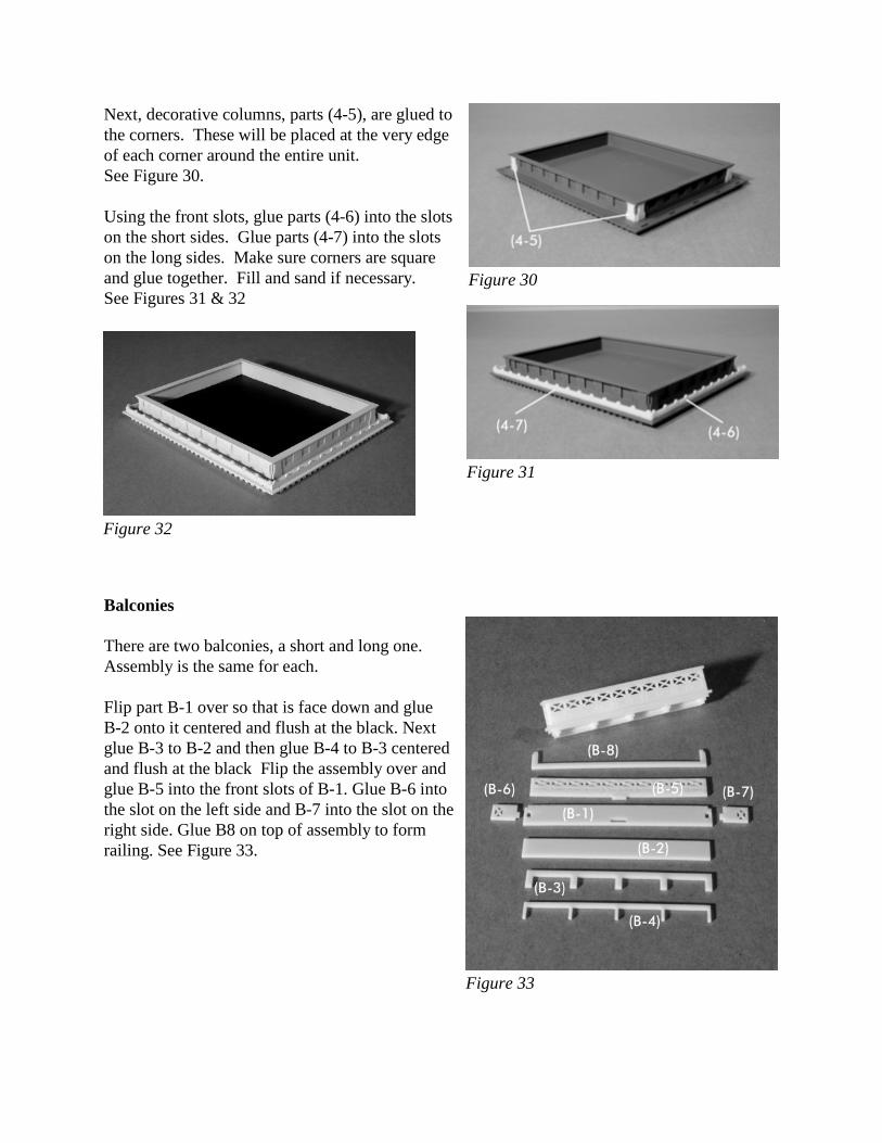
Next, decorative columns, parts (4-5), are glued tothe corners. These will be placed at the very edgeof each corner around the entire unit. See Figure 30.
Using the front slots, glue parts (4-6) into the slotson the short sides. Glue parts (4-7) into the slotson the long sides. Make sure corners are squareand glue together. Fill and sand if necessary. See Figures 31 & 32
Balconies
There are two balconies, a short and long one.Assembly is the same for each.
Flip part B-1 over so that is face down and glueB-2 onto it centered and flush at the black. Nextglue B-3 to B-2 and then glue B-4 to B-3 centeredand flush at the black Flip the assembly over andglue B-5 into the front slots of B-1. Glue B-6 intothe slot on the left side and B-7 into the slot on theright side. Glue B8 on top of assembly to formrailing. See Figure 33.
Figure 30
Figure 31
Figure 32
Figure 33
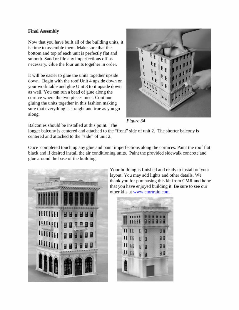
Final Assembly
Now that you have built all of the building units, itis time to assemble them. Make sure that thebottom and top of each unit is perfectly flat andsmooth. Sand or file any imperfections off asnecessary. Glue the four units together in order.
It will be easier to glue the units together upsidedown. Begin with the roof Unit 4 upside down onyour work table and glue Unit 3 to it upside downas well. You can run a bead of glue along thecornice where the two pieces meet. Continuegluing the units together in this fashion makingsure that everything is straight and true as you goalong.
Balconies should be installed at this point. Thelonger balcony is centered and attached to the “front” side of unit 2. The shorter balcony iscentered and attached to the “side” of unit 2.
Once completed touch up any glue and paint imperfections along the cornices. Paint the roof flatblack and if desired install the air conditioning units. Paint the provided sidewalk concrete andglue around the base of the building.
Your building is finished and ready to install on yourlayout. You may add lights and other details. Wethank you for purchasing this kit from CMR and hopethat you have enjoyed building it. Be sure to see ourother kits at www.cmrtrain.com
Figure 34