the effect of use styrofoam for flexural characteristics
TRANSCRIPT

2nd International Conference on Engineering and Technology Development (ICETD 2013) Universitas Bandar Lampung Faculty of Engineering and Faculty of Computer Science
261
ISSN 2301-6590
The Effect of Use Styrofoam for Flexural Characteristics of Reinforced Concrete Beams
Yasser 1), Herman Parung 2), M. Wihardi Tjaronge3), Rudy Djamaluddin 4) 1Doktoral Student Graduate School of Civil Engineering, Civil Engineering Department
Engineering Faculty of Hasanuddin University, Perintis Kemerdekaan KM-10 Makassar 90245, e-mail :
[email protected] 2Professor Graduate School of Civil Engineering, Civil Engineering Department Engineering
Faculty of Hasanuddin University, Perintis Kemerdekaan KM-10 Makassar 90245, email :
[email protected] 3Professor Graduate School of Civil Engineering, Civil Engineering Department Engineering
Faculty of Hasanuddin University, Perintis Kemerdekaan KM-10 Makassar 90245, email :
[email protected] 4Associate Professor Graduate School of Civil Engineering,Civil Engineering Department
Engineering Faculty of Hasanuddin University, Perintis Kemerdekaan KM-10 Makassar 90245, email :
Abstract-In general bending loads acting on structural elements of concrete beams arrested by the bottom cross secttion on the compression area while the tension area is ignored. Therefore, it is reasonable if the concrete beam section on the tension area is minimized with concrete mass reduction in tensile region by ignoring concrete tensile stress while receiving static loads or the area is filled with styrofoam concrete (styrocon). One effort to effeciency concrete economic value by reducing the concrete and use of styrocon thus component volume of natural materials, such as sand mining, coarse aggregate, and cement and weight of construction becomes smaller. Styrofoam as waste can be used as filler to reduce the volume of concrete, especially for areas where the concrete section is not working mechanically. In an effort to study the flexural strength of external reinforced concrete beams and styrofoam-filled composite, then performed a series of tests. Test material in the form of beams with dimensions of 15 cm x 20 cm x 270 cm. Test material consisted of normal beam quality 26.0 MPa concrete with transverse reinforcement as a control beam and test materials with external transverse reinforced and truss systems and styrofoam-filled composite. In the normal-styrocon composite beams with various content of styrofoam. Beam placed on 2 simple supports with 2 point loading test method. Results showed flexural capacity of the normal concrete beam is 36.7 kN, but the external reinforced beams decreased 30.6 kN, but external reinforced truss system beams is relatively equal 35.8 kN. But external reinforced beams prone to corrosion and fire and require maintenance. Therefore used styrocon on the outer portion with styrofoam content of 30%, 40%, and 50% who had a flexural strength of each 33.8 kN, 31.0 kN and 29.0 kN. It can be concluded that the use of composite concrete beams normal-styrocon can efficiency use natural materials to reduce the weight of the concrete beam and construction as well as having environmental aspects by using the waste. Key words: flexural strength, sandwich concrete beams, styrocon, external reinforcement, monotonic load.

2nd International Conference on Engineering and Technology Development (ICETD 2013) Universitas Bandar Lampung Faculty of Engineering and Faculty of Computer Science
262
ISSN 2301-6590
INTRODUCTION
Concrete is still one of the most widely used material in the world and it is estimated that the annual global production of more than 2 billion cubic meters [1]. Formed from a hardened mixture of cement, water, fine aggregate and coarse aggregate. As the main constituent of concrete materials are natural materials that the decrease in the deposite so that necessary improvement to the study on the efficiency of the assessment of natural materials that are used in the optimum design of building structures, especially in the bridge girder. Figure 1 shows the implementation of the joint-roller support on construction elements.
Of the various theories relating to the analysis of structural elements concrete beams, note that the part that works optimally in its support withstand bending force only the bottom of cross section only. Its in the compression area of concrete, while the the tension area of concrete, strength negligible [2]. Therefore it is not efficient when the concrete core parts that are not working optimally made from the same type of concrete with which to work optimally.
Fig. 1: Applications for Simple beam
Seeing these inefficiencies arose then thought to make concrete that consists of several different layers [3]. Figure 2 shows the concrete beam that consists of several different layers. With this, we can to efficiency design of structural elements made of concrete beams by using normal concrete in certain layers while the other part is filled with lightweight concrete styrocon using styrofoam.
With the use of styrocon the total weight of the concrete and the structure will be lighter which automatically reduces the dimension of the structure, so that the optimal design can be achieved. But the weakness such as lightweight concrete has a lower stiffness and creep and shrinkage greater. Therefore this material tends to be placed in a position near the neutral line or the bottom. With a efficiency concrete layer on work in resist bending, theoretically, to see the advantages and disadvantages of normal concrete and lightweight, it is expected the combination of the two types of concrete to composite, so that each type of concrete can overlap each other's shortcomings.
Styrofoam or expanded polystyrene is known as a white foam which is used for packaging electronic items often become garbage. Figure 3 shows an example of styrofoam.
Polystyrene is produced from styrene (C6H5CH9CH2) that can not be decomposed by soil thus reducing the quality of the fertility of the land, when burned produces carbon oxides (COX), which lead to global warming as well as the combustion of a liquid plastic that can lead to pollution of soil and water. It is therefore necessary environmental friendly concrete technology with reuse the waste at the beam structural element for to reduce the pollution. So the use of lightweight concrete styrocon the core layer or bottom layer normal-lightweight beam in addition to reducing of the construction weight also has the environmental aspects.

2nd International Conference on Engineering and Technology Development (ICETD 2013) Universitas Bandar Lampung Faculty of Engineering and Faculty of Computer Science
263
ISSN 2301-6590
Fig. 2: Sandwich concrete beam section
Fig. 3: Styrofoam
Use Styrofoam in concrete material by utilizing waste concrete can reduce construction costs, slowing the onset of the heat of hydration, lower density of concrete, and reduce the work load earthquakes is smaller due to heavy concrete structures is reduced [4,5]. That in the end the exploitation of natural materials such as sand, gravel, and cement for building materials can be reduced.
Motivation to investigate the performance of sandwich beams of normal and lightweight concrete is to design structural elements that utilize the most advantageous properties of two different concrete quality and they are in one section. Sandwich beams are used in applications requiring high bending stiffness and strength combined low weight [6,7].
Studies on the use of truss system reinforcement of structural elements have been conducted by several researchers such as Salmon et. al. [8] which uses steel trusses on the panel to reduce deflection shell. Deshpande et.al. [9] conducted experimental sandwich beam, which consists of a triangular truss core face-sheets, which have been casted with aluminum-silicon alloy and
silicon in brass to get macroscopic effective stiffness and strength sheet face-sheets and tetrahedral core. Kocher et. al. [10] presents a theoretical approach to study several issues related to the design of sandwich structures with a polymer frame reinforced with hollow core using a simple analytical model that describes the contribution to the stability of the structure is hollow at the core. Liu et.al. [11] studied a multi-parameter optimization procedure on the panel Ultralightweight truss-core sandwich. Optimization of improving structural performance of each panel in the case of multiple loading and minimize structural weight simultaneously. Kabir [12] developed a method to investigate the mechanical characteristics of the 3D sandwich wall panel in shear and flexural static load, in order to understand the structural components.
In general, the research related to the utilization of waste syrofoam for use in beam structural elements for purposes of efficiency of use of natural materials in concrete construction and application of environmentally suistenable technologies. In this regard it is important to expand the use of styrofoam to reuse the waste. To study the application materials for the substitution of natural materials styrofoam, it has done a series of analytical studies and experimental testing. This paper presents the results of a study that is related to the flexural capacity of concrete beams using material with styrofoam-filled.
Styrofoam or expanded polystyrene is known as a white foam which is used for packaging electronic items often become garbage. Polystyrene is produced from styrene (C6H5CH9CH2) that can not be decomposed by soil thus reducing the quality of the fertility of the land, when burned produces carbon oxides (COX), which lead to global warming as well as the combustion of a liquid plastic that can lead to pollution of soil and water. It is therefore necessary environmental friendly concrete technology with me reuse the waste at the beam structural element for me reduce the pollution. So the use of lightweight concrete styrocon the core layer or bottom layer

2nd International Conference on Engineering and Technology Development (ICETD 2013) Universitas Bandar Lampung Faculty of Engineering and Faculty of Computer Science
264
ISSN 2301-6590
normal-light sandwich beam in addition to reducing the weight of construction also has environmental aspects.
METHODS AND MATERIALS TESTING
(g) Beams BN
(h) Beams BTL
(i) Beams BTR
(j) Beams BSC30
(k) Beams BSC40
(l) Beams BSC50
Fig. 4:. Details of test materials
Figure 4. shows the specimen for each
control beam (BN), external transverse reinforced beams (BTL), external truss system reinforced beam (BTR), normal-styrocon beam with styrofoam content of 30% (BSC30), normal-styrocon beam with styrofoam content of 40% (BSC40), and normal-styrocon beam with styrofoam content of 50% (BSC50). Specimens BN are intended as a test or as a comparison control beam while BTL, BTR, BSC30, BSC40 and BSC50 as a competitor, which beams provide the strength and efficiency of natural materials usages.
Table 1: Characteristics of concrete and reinforcing steel
Table 2: Specifications expanded polystyrene / styrofoam
All test materials are beams with
dimensions of long 270 cm, wide beam 15 cm, and high beam 20 cm in Figure 5. Reinforced concrete beams have planned reinforcement tensile reinforcement 3 bars diameter 10 mm with a diameter of 6 mm shear reinforcement. To facilitate the assembly of reinforcement, then on the compression area also given 2 reinforcement with diameter of 6 mm. Materials have the
2nd International Conference on Engineering and Technology Development (ICETD 2013) Universitas Bandar Lampung Faculty of Engineering and Faculty of Computer Science
265
ISSN 2301-6590
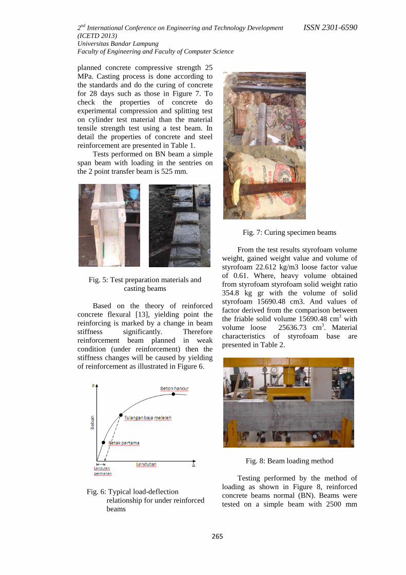
planned concrete compressive strength 25 MPa. Casting process is done according to the standards and do the curing of concrete for 28 days such as those in Figure 7. To check the properties of concrete do experimental compression and splitting test on cylinder test material than the material tensile strength test using a test beam. In detail the properties of concrete and steel reinforcement are presented in Table 1.
Tests performed on BN beam a simple span beam with loading in the sentries on the 2 point transfer beam is 525 mm.
Fig. 5: Test preparation materials and casting beams
Based on the theory of reinforced
concrete flexural [13], yielding point the reinforcing is marked by a change in beam stiffness significantly. Therefore reinforcement beam planned in weak condition (under reinforcement) then the stiffness changes will be caused by yielding of reinforcement as illustrated in Figure 6.
Fig. 6: Typical load-deflection relationship for under reinforced beams
Fig. 7: Curing specimen beams From the test results styrofoam volume
weight, gained weight value and volume of styrofoam 22.612 kg/m3 loose factor value of 0.61. Where, heavy volume obtained from styrofoam styrofoam solid weight ratio 354.8 kg gr with the volume of solid styrofoam 15690.48 cm3. And values of factor derived from the comparison between the friable solid volume 15690.48 cm3 with volume loose 25636.73 cm3. Material characteristics of styrofoam base are presented in Table 2.
Fig. 8: Beam loading method
Testing performed by the method of loading as shown in Figure 8, reinforced concrete beams normal (BN). Beams were tested on a simple beam with 2500 mm

2nd International Conference on Engineering and Technology Development (ICETD 2013) Universitas Bandar Lampung Faculty of Engineering and Faculty of Computer Science
266
ISSN 2301-6590
distance between the support. Load is given in the form of 2 points loading is 500 mm as sentries at midspan. Loading is done in stages per 1 kN using a manual hydraulic jack. Deflection measurements done by placing 3 pieces of the dial gauge on the center span and the point load. Jack dial load readings done on every 1 kN load increase. It also made observations of the cracks that occurred. Cracks that appear later in the sketch. Observe the propagation of cracks, then selected 3 major cracks to be analyzed.
ESTIMATED FLEXURAL CAPACITY
Figure 9 section illustrates the basic assumption of strain cross section, stress and the forces in the analysis of flexural capacities. Assumptions are based on cross-sectional under reinforced (ρs <ρsb). Based
on the flexural theory of reinforced concrete [13], it is also assumed in this analysis that occurs linearly varying strain relationship in cross section perfect adhesiveness between the concrete and the reinforcing steel in the concrete strain collapse condition is 0.003. It is also assumed that the cross section of concrete compressive stress at ultimate capacity is rectangular and steel reinforcement behave elasto-plastically.
Fig. 9: Model of stress-strain Beam on a particular condition can
withstand loads that occur up to a maximum concrete compressive strain bending (ε'c)max reaches 0.003 while the tensile stress tension reinforcement reaches yielding force fy. If
that happens, then the value of fs = fy and named section to reach equilibrium strain (balanced reinforced).
Based on the assumptions outlined
above, can be tested strain, stress, and the forces that arise in cross-section beam that works withstand the moment ultimate (Mu), the moment caused by the external load in the event of destruction. Flexural strength of concrete beams occurs due to ongoing mechanisms in stress-strain arising in the beam, in certain circumstances may be represented by the internal forces. Where ND is the internally resultant compressive force and a resultant compressive force in the area that is above the neutral line. While the NT is a internally resultant tensile force and the tensile strength are all planned for the area just below the neutral line. Resultant compressive force and the resultant tensile force in the direction parallel to the line of work, but the opposite direction is equal to the distance z to form coupling in internally moment, where the maximum value is referred to as flexural strength.
The internally moment will carry bending moments caused by the actual plan of external load. For planning purposes on the condition of the beam must be prepared in accordance with the loaded composition concrete beam dimensions and the amount of reinforcement area to resist the moment due to external loads. First was to determine the total resultant concrete force hit ND, and the location of the line of work force calculated to press the outer edge of the cross section, so that the distance z can be calculated. ND and NT values can be calculated by simplifying the curvilinear form of the stress distribution changed to a simpler equivalent form, by using the stress intensity value of the average order value and the resultant layout has not changed.
Based rectangular, concrete stress intensity hit an average of 0.85 f'c determined and assumed to work in the area and the press beam section width b and height a, the amount can be determined by the equation:
a = β1c (2)

2nd International Conference on Engineering and Technology Development (ICETD 2013) Universitas Bandar Lampung Faculty of Engineering and Faculty of Computer Science
267
ISSN 2301-6590
For underreinforced beam bending collapse marked by the melting of reinforcement while the voltage that occurs in a small concrete (fc <fc '). Elastic limit where the value fs = fy. So the moment that happened as the following equation:
My = fy.As.jd (2)
After the steel stress equal to the yield stress occurs then it is said steel beam has undergone ductile bending. In case of beam bending ductile deformation without the collapse of the tensile reinforcement.
Of the force balance equation Cc + Cs = T, then:
As.fy = 0,85fc.b.a + As’.fy (3)
or
a = (As.fy - As’.fy)/( 0,85fc.b) (4)
while to determine the ultimate moment:
Mu = 0,85.fc.a.b(d-a/2) + As’.fy(d-d’) (5)
Table 3 presents the estimation results for the ultimate moment of each test material using the material properties are presented in Table 2. Moment of initial crack is estimated using the elastic flexural theory [13]. For the moment ultimate, estimates carried out under conditions where failure occurs after a tap on the concrete reinforcing steel yielded by using a eq. (5).
From Table 3 it can be seen that the estimation for normally reinforced beams (BN) has the ultimate load of 28.77 kN. Externally reinforced beam relative to the same, but in order to show an increase in truss system reinforcement. For normal-styrofoam composite beams showed a better condition than the externally reinforced beam. So can efficiency to use of natural materials and reuse the waste on the beam structural elements.
Table 3: Estimation of moment initial crack
and moment ultimate
RESULTS AND DISCUSSION Load and Deflection relationship
Figure 10. Load and deflection relationship
Table 4: Cracking load and ultimate load test results

2nd International Conference on Engineering and Technology Development (ICETD 2013) Universitas Bandar Lampung Faculty of Engineering and Faculty of Computer Science
268
ISSN 2301-6590
Fig. 11: Level of deviation between the
test results with theoretical estimates
Figure 10 shows the relationship between load and deflection of each of the specimens. On BN beam, early loading is a straight line that shows the elastic behavior until the load average of 8 kN (working stage). In line with the increased load, the load and deflection relationship is more gentle than before. This occurs until the load average of 32 kN (yielding stage). At the time of yielding steel experience characterized by large deflections increase without a corresponding increase in the mean load, and the load deflection curve is much flatter than before. This occurs until the ultimate load average of 37 kN (collapse stage).
On BTL beam lower ultimate response of BN and are relatively brittle. While on BTR with truss system reinforcement
showed an increase in ultimate load compared to BTL but still not ductile. BSC30 beam showed a condition that is more ductile than the BN with the addition of styrofoam by 30% in the tensile concrete. So can efficiency to use of natural materials and reuse the waste on the beam structural elements. BSC40 and BSC50 beams, the capacity of each lower than BSC30.
(g) Specimen BN
(h) Specimen BTL
(i) Specimen BTR
(j) Specimen BSC30
(k) Material test BSC40
(l) Specimen BSC50
Fig. 12: Direction of crack propagation
Flexural Capacity
Table 4 presents a summary of the load
at the time of the initial crack and the ultimate load current of each control beam (Specimen BN), externally reinforced beams (Specimens BLT and BTR), and normal-styrocon composite beam (Specimen

2nd International Conference on Engineering and Technology Development (ICETD 2013) Universitas Bandar Lampung Faculty of Engineering and Faculty of Computer Science
269
ISSN 2301-6590
BSC30, BSC40, and BSC40). In general for all the materials ultimate load test results of the test have in common ratio is quite good compared with theoretical estimates as shown in Figure 11, which shows the level of deviation between the test results with theoretical estimates.
BSC50 beam ultimate load test results achieved at the level of 29.0 kN load. When compared with the theoretical estimation using strain and stress assumptions described above, shows good results with a ratio of 98.6% similarity. This indicates that the test substance BSC50 behave as assumed in the theoretical estimation.
For BTL test material has the lowest flexural capacity with another specimen of the test material BN and behave brittle. BTR beam flexural capacity closest to BN, but showed no ductile characteristics. BSC30 beam flexural capacity of the beam also approached BN and exhibit behavior that is more ductile materials such comparison test, which gives the efficiency of the use of natural materials, such as sand, gravel, and cement by 30% in the tension area. Besides reusing waste or garbage packaging these electronic tools.
BSC40 and BSC50 test materials have a lower ultimate load. Thus provide less capacity than the pliable material BN test.
(b) Specimen BN (b) Specimen BTL
(d) Specimen BTR (d)
Specimen BSC30
(f) Specimen BSC40 (f) Specimen BSC50
Fig. 13: Crack propagation pattern
(b) Specimen BN (b) Specimen BTL
(d) Specimen BTR (d) Specimen BSC30

2nd International Conference on Engineering and Technology Development (ICETD 2013) Universitas Bandar Lampung Faculty of Engineering and Faculty of Computer Science
270
ISSN 2301-6590
(f) Specimen BSC40 (f) Specimen BSC50
Fig. 14: Collapse of the test material
Cracks and Failure Pattern
In general, the pattern of cracks as shown in Figure 12 is a flexural cracks began to occur when the force stress exceeds the tensile strength of concrete material. The addition of the load will cause the spread of adhesiveness pointing up toward the neutral line of the beam as well as the emergence of new cracks.
Beam collapse at maximum load characterized by widening cracks and yielding of steel which is characterized by a large deflection to the beam had destroyed the compression area. On reinforced concrete beams with Styrofoam-filled, long cracks which occur more slowly than the long cracks in reinforced concrete beams normal (BN).
Monitoring of the 3 crack propagation in each of the test material is presented in Figure 13. Looks can be observed on the beam BN that cracks began to spread when the load is at the level of about 8 kN. Cracks continue to spread until they reached ultimate load beam. On the externally reinforced beam BTL and BTR can be observed cracks began to spread after the load is at a level slightly higher than the initial crack load beam BN, but faster initial collapse because cracks have been in the compression area of the concrete beams.
Based on the pattern of cracks and crack propagation phenomena as shown in Figure 12 and Figure 13, it can be concluded that the beam is Styrofoam-filled give advantages and well conditions, the length of crack propagation patterns are not straight up, compared to the normal beam (BN) and
externally reiforced beams (BTL and BTR), due to the addition of expanded polistyerene styrocon have more elongation than normal concrete.
Figure 14 shows the photographs test materials were damaged. All specimens showed flexural collapse. But on BTR test materials with truss reinforcement shows reduction deflection, but after the compression area cracked concrete directly experiencing failure. In the normal beam (BN) damage also occurred to the upper part of the concrete. While in the normal- styrocon composite concrete collapse until the high force block quadrilateral Whitney, caused the tensile strength styrofoam-filled concrete has better tensile strength than normal concrete. CONCLUSION
Based on the testing and analysis, it can be drawn some conclusions as follows: 6. Relationships load and deflection in the
normal-styrocon composite concrete beams with the addition of 30% styrofoam exhibits behavior quite well on ductility displacement than normal concrete beams. Moreover, it can efficiency use of natural materials, such as sand, gravel, and cement by 30% on the tension area of cross-section and reduce the weight of construction and reuse of waste or garbage white wrapping cork electronic devices.
7. Flexural capacity of composite concrete beams with normal-styrocon addition of 30% styrofoam, have the ability withstand ultimate load of 34.5 kN, and the addition of expanded material on tension polistyerene styrocon area has resulted in higher elongation than normal concrete, so it has better flexibility as well.
8. In the normal-styrocon composite concrete beams with the addition of 30% styrofoam crack length is happening more slowly than the long cracks in normally reinforced concrete beams and externally reinforced concrete beam where crack propagation patterns are not straight up.

2nd International Conference on Engineering and Technology Development (ICETD 2013) Universitas Bandar Lampung Faculty of Engineering and Faculty of Computer Science
271
ISSN 2301-6590
9. The test results showed that achieved good results with the similarity ratio of 98.6% compared with the theoretical estimation, this indicates that the test substance behaves as assumed in the theoretical estimation.
10. Need to develop methods of strengthening the ability of adhesiveness between the two layers of normal-styrocon composite concrete is to increase the strength and stability of the sandwich concrete beams.
ACKNOWLEDGEMENTS
In particular thanks are given to the Eco Materials Laboratory and the Research Laboratory of Earthquake and Structural Engineering, Department of Civil Engineering, Hasanuddin University for their cooperation and technical advice so that the study can be done well. REFERENCES 14. Jacobsen, S. (2006). Lecture Notes,
BM3. Trondheim: NTNU. 15. Nawy, E. G. (1998). Reinforced
Concrete A Fundamental Aproach. Third Edition, Prentice-Hall, Inc.
16. Schaumann, E., Valle, T. and Keller, T.(2008). ―Direct Load Transmission in
Sandwich Slabs with Lightweight Concrete Core‖. Journal of Tailor Made Concrete Structures-Walraven & Stoelhorst (eds), Taylor & Francis Group, London, 849-855.
17. Satyarno. I. (2006). ―Ligthweight
Styrofoam Concrete for Lighter and More Wall Ductile‖. Jurnal HAKI, Yogyakarta.
18. Giri, I. B. D., Sudarsana, I. K., dan Tutarani, N. M. (2008). ―Kuat Tekan
dan Modulus Elastisitas Beton dengan Penambahan Styrofoam (Styrocon)‖. Jurnal Ilmiah Teknik Sipil Vol. 12, No. 1, Denpasar.
19. Skjølberg, O. G. and Hansson, A. (2010). ―Hybrid Concrete Structures : Experimental Testing and Numerical Simulation of Structural Element‖.
Department of Structural Engineering, Faculty of Engineering Science and
Technology, NTNU - Norwegian University of Science and Technology.
20. Nes, L. G. and Overli, J. A. (2011). ―Composite and Hybrids Investigation of Material Parameters and Structural Performance of a Concrete Sandwich Slab Element‖. fib Symposium PRAQUE, Session 5-6.
21. Salmon, D. C. and Einea A. (1995). ―Partially Composites Sandwich Panel
Deflections‖. Journal of Structural Engineering. ASCE, Vol. 121, No. 4, April, 778-783.
22. Despandhe, V. S. and Fleck, N. A. (2001). ―Collapse of Truss Core
Sandwich Beams in 3-Point Bending‖. International of Solid and Structures, Pergamon, 38, 6275-6305.
23. Kocher, C., Watson, W., Gomez, M. and Birman, V. (2002). ―Integrity of Sandwich Panels ands Beams with Truss-Reinforced Cores‖. Journal of Aerospace Engineering, ASCE, Vol. 15, No. 3, July, 111-117.
24. Liu, J. S. and Lu, T. J. (2004). ―Multi-Objectif and Multi-Loading Optimization of Ultraweight Truss Material‖. International Journal of Solids and Structures, Elsevier, 41 (2004), 24 September 2004, 619-635.
25. Kabir, M. Z. 2005. ―Structural
Performance of 3-D Sandwich Panel Under Shear and Flexural Loading‖. Journal of Scientica Iranica, Vol. 12 No. 4, October 2005, 402-408.
26. Wight, J. K. and MacGregor, J. G. (2005). Reinforced Concrete Mechanics and Design. Sixth Edition, Pearson.
NOTASI a = Height Whitney rectangular stress block (mm) As = Area of cross section of tensile steel
reinforcement (mm2) As‘ = Area of cross section of compresion
steel reinforcement (mm2) b = Width of beam (mm) c = Distance to the outer edge of the
neutral line (mm) d = Effective reinforcement steel Height
(mm) d' = Concrete cover thickness (mm)

2nd International Conference on Engineering and Technology Development (ICETD 2013) Universitas Bandar Lampung Faculty of Engineering and Faculty of Computer Science
272
ISSN 2301-6590
f'c = Compressive strength of concrete (N/mm2) fy = Yield force of steel reinforcement (N/mm2) h = High beam (mm) Icr = Moment of inertia of cracked
reinforced concrete section (mm4) Ig = Moment inesia reinforced concrete
section (mm4) Mn= Moment nominal section (N.mm) Mu= Moment ultimate section (N.mm) ND= Resultant compressive force above the
neutral line (N) NT = Resultant tensile force below the neutral line (N) z = Distance resultant tensile force to the
resultant compressive force (mm) β1 = Coefficient correction Whitney
rectangular stress block height (mm) εcu =Ultimate concrete strain press