the effect of tunnel depth on the variations of rock bolt ... · the effect of tunnel depth on the...
TRANSCRIPT

14
International Journal of
Science and Engineering Investigations vol. 5, issue 57, October 2016
ISSN: 2251-8843
The Effect of Tunnel Depth on the Variations of Rock Bolt’s
Axial Forces in Seismic Mode
Saeed Mojtabazadeh Hasanlouyi
1, Davood Nazari
2, Mohammad Taghi Emami Fard
3, Reza Rezaei
4, Mahdi Tahmasebi
5
1,2,3,4,5Department of Civil Engineering, Zanjan Branch, Islamic Azad University, Zanjan, Iran
Abstract-In this study, through Pseudo-static analysis with the help of finite element modeling software phase
2, effect the
tunnel depth and the direction of seismic coefficients on the axial force of rock bolts mounted in circular tunnels and it variations in different conditions evaluated. The circular tunnels are modeled with a diameter of 4 meters and in depths of 5, 10, 25 and 35 meters in the Shale rocks. The tunnels are supported by end anchored rock bolts with length of 3 meters and spacing of 2 meters. Also the ground surface modeled with the dip of 5 degrees and the earthquake magnitudes of 6.5, 7, 7.5 and 8 on the Richter scale considered. The results of the evaluations show that with increasing the tunnel depth, the variations of axial forces have decreased because of reduction in displacements around tunnel. Furthermore, in greater earthquake magnitudes, the variations of rock bolts' axial forces have increased because, they forces the tunnel to have more movements and in this condition, the rock bolts are under higher tensile stresses. Moreover, in steep surfaces for tunnels with small sections (tunnel diameter less than or equal to 4 meters), the alignment of horizontal acceleration of seismic coefficient with steep direction and the opposite direction of vertical seismic coefficient with gravitational force had resulted in the highest variance of rock bolts’ axial force.
Keywords- Axial force, Rock bolt, Seismic Coefficient, Tunnel,
Phase2
I. INTRODUCTION
Tunnels are vital underground structures that can withstand earthquakes. Although underground structures, in comparison to surface structures are of high safety regarding seismic waves, historical evidence and earthquake reports show that these structures are vulnerable to waves which result from earthquake and outbreak of damage and destruction is possible.
One of the ways to stabilizing of tunnels is application of rock bolts. A rock bolt is a long anchor bolt, for stabilizing rock excavations, which may be used in tunnels or rock slopes. It transfers load from the unstable exterior to the confined interior of the rock mass. The rock bolts are almost always installed in a pattern, the design of which depends on the rock quality designation and the type of excavation [1].
Rock bolts have been used for years to reinforce the surface and near surface rock of excavated or natural slopes. They are used to improve the stability and load bearing characteristics of a rock mass. When rock bolts are used to reinforce a fractured rock mass, the rock bolts will be subjected to tension, shear and compressive forces. The studies have been done by researchers [2, 3, 4] to reinforce the slopes with rock anchoring. A general rule for rock bolts is that the distance between rock bolts should be approximately equal to three times the average spacing of the planes of weakness in the rock mass, and the bolt length should be twice the bolt spacing [5].
Tunnels excavate in various rock masses and ground conditions with different modes of behavior. The way the rock masses surrounding a tunnel behave is very important. The behavior of steep ground largely depends on the degree of surface dip and the shape and size of underground excavation. The ground behavior can be assessed via ground conditions with various project features. The rock masses whose strength is lower than the surrounding stress can be considered as weak rocks. The behavior of weak rocks in tunnels has led to problems during the construction of a number of projects. The ratio of rock mass strength to the in situ stress value specifies that deformations induce stability problems in the tunnel. The analysis of circular tunnels excavated in weak rocks under hydrostatic stress fields has been one of the principal sources of knowledge.
Due to excavation of tunnel in weak rocks, the surface settlement of ground could be occurred. The displacements at the surface of ground and the displacement distributions around tunnels varying in the plastic zone. In this matter, the theories are investigated by [6] and [7].
Furthermore, excavating underground structures in rock mass, causes stress changes in the underground environment and this phenomenon can cause displacements in these areas. Also the displacements caused by excavation may cause induced stress on the support system of the tunnels and finally can end with instability of the tunnel surrounding area [8].
Moreover, applying the earthquake to the tunnel can cause compressive and tensile stresses too, which can lead to the destruction of a temporary tunnel supporting system or even to a complete closure of the tunnel cross section [9].

International Journal of Science and Engineering Investigations, Volume 5, Issue 57, October 2016 15
www.IJSEI.com Paper ID: 55716-03 ISSN: 2251-8843
In this research in order to study the tunnel depth and the effect of seismic coefficients direction on the variations of rock bolts' axial forces, the circular tunnels with diameter of 4 meters and in depths of 5, 10, 25 and 35 meters are modeled and the ground surface dip of 5 degrees is considered in modelings.
II. THE PHYSICAL AND MECHANICAL CHARACTERISTICS
OF THE SHALE ROCKS
The rock mass properties such as the rock mass strength (σcm), the rock mass deformation modulus (Em) and the rock mass constants (mb, s and a) were calculated by the RocLab program defined by [10] (Table 1). This program has been developed to provide a convenient means of solving and plotting the equations presented by [10].
In RocLab program, both the rock mass strength and deformation modulus were calculated using equations of [10]. In addition, the rock mass constants were estimated using equations of Geological Strength Index (GSI) [10] together with the value of the shale material constant (mi). Also, the value of disturbance factor (D) that depends on the amount of disturbance in the rock mass associated with the excavation method was considered equal to 0.2 for the shale rocks in Table 1.
TABLE I. GEOMECHANICAL PARAMETERS OF SHALE ROCK MASS
OBTAINED BY USING ROCLAB SOFTWARE
Input and output of RocLab software
Hoek-Brown classification Heok-Brown criterion
ci (Mpa) GSI mi D Mb s a
Intact
Uniaxial
compressive
strength
Geological
strength
index
Constant
Hoek-Brown
criterion for
intact rock
Disturbance
Factor Heok-Brown criterion
35 32 6 0.2 0.404 0.0003 0.520
Parameters of the
Mohr-Coulomb
equivalent
Rock mass Parameters
Mohr-Coulomb Fit Rock Mass Parameters
C (Mpa) (degree) t (Mpa) c (Mpa) cm
(Mpa) Erm (Mpa)
Cohesion Friction
angle
Tensile
strength
Uniaxial
compressive
strength
Global
strength
Deformation
modulus
0.079 54.04 -0.026 0.522 2.700 495
Figure 1. The Hoek-Brown failure envelope of shale rock masses in the
depth of 5 meters.
Figure 2. The Hoek-Brown failure envelope of shale rock masses in the
depth of 10 meters.
Figure 3. The Hoek-Brown failure envelope of shale rock masses in the depth of 25 meters.

International Journal of Science and Engineering Investigations, Volume 5, Issue 57, October 2016 16
www.IJSEI.com Paper ID: 55716-03 ISSN: 2251-8843
Figure 4. The Hoek-Brown failure envelope of shale rock masses in the
depth of 35 meters.
The Hoek-Brown failure envelope of shale rock masses for different depths is obtained and presented in Figs. 1 to 4.
In order to achieve more accurate results, material properties defined for each depth of tunnels separately and individually applied to different models with different depths.
III. NUMERICAL ANALYSIS
Numerical analyses are done using a two-dimensional hybrid element model, called Phase
2 Finite Element Program
[11]. This software is used to simulate the two-dimensional excavation of a tunnel. In this finite element simulation, based on the elasto-plastic analysis, deformations and stresses are computed. These analyses used for evaluations of the tunnel stability in the rock masses. The geomechanical properties for these analyses are extracted from Table 1. The generalized Hoek and Brown failure criterion is used to identify elements undergoing yielding and the displacements of the rock masses in the tunnel surrounding.
To simulate the excavation of tunnels in the shale rock masses, a finite element models is generated for circular tunnels with diameter of 4 meters and in depths of 5, 10, 25 and 35 meters. Also the dip of 5 degrees to the horizon is considered for the ground surface. The six-nodded triangular elements are used in the finite element mesh. The end anchored bolts with length of 3 meters and spacing of 2 meters is used for reinforcement of tunnels. Fig. 5. shows different depths of tunnels modeling.
Figure 5. The modeling of circular tunnels with a diameter of 4 meters and
in depths of 5, 10, 25 and 35 meters. The dip of ground surface is 5 degrees to the horizon.
A set of numerical analysis case studies were carried out to investigate the effect of horizontal and vertical seismic coefficient in steep ground using the pseudo-static seismic loading procedure. Four seismic loading scenarios, as shown in below are applied to the models.
At first, it's necessary to mention that when horizontal seismic coefficient (Kh) is positive, it applies to right side and when it's negative, applies to left side. Furthermore, for vertical seismic coefficient (Kv), positive value means upward and negative value means downward.
1) Kh = + value and Kv = 0. In this case the effect of vertical seismic coefficient ignored and sets it equal to zero.
2) Kh = + value and Kv = + value too. This seismic loading scenario considers a positive horizontal and vertical seismic coefficient. In this case, the vertical seismic coefficient is adding an inertial force and in the opposite direction as the downward force due to gravity.
3) Kh = + value and Kv = - value. This loading case the sign of the vertical seismic coefficient is negative. Thus, the inertial
International Journal of Science and Engineering Investigations, Volume 5, Issue 57, October 2016 17
www.IJSEI.com Paper ID: 55716-03 ISSN: 2251-8843
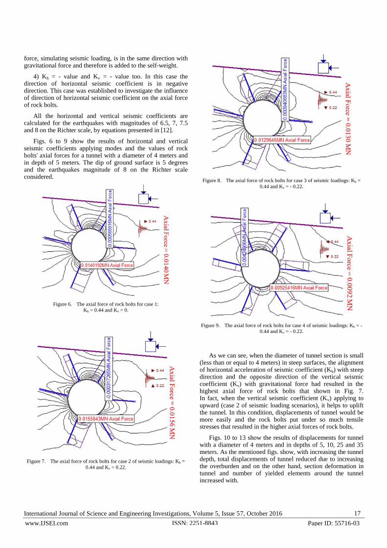
force, simulating seismic loading, is in the same direction with gravitational force and therefore is added to the self-weight.
4) Kh = - value and Kv = - value too. In this case the direction of horizontal seismic coefficient is in negative direction. This case was established to investigate the influence of direction of horizontal seismic coefficient on the axial force of rock bolts.
All the horizontal and vertical seismic coefficients are calculated for the earthquakes with magnitudes of 6.5, 7, 7.5 and 8 on the Richter scale, by equations presented in [12].
Figs. 6 to 9 show the results of horizontal and vertical seismic coefficients applying modes and the values of rock bolts' axial forces for a tunnel with a diameter of 4 meters and in depth of 5 meters. The dip of ground surface is 5 degrees and the earthquakes magnitude of 8 on the Richter scale considered.
Figure 6. The axial force of rock bolts for case 1: Kh = 0.44 and Kv = 0.
Figure 7. The axial force of rock bolts for case 2 of seismic loadings: Kh =
0.44 and Kv = 0.22.
Figure 8. The axial force of rock bolts for case 3 of seismic loadings: Kh =
0.44 and Kv = - 0.22.
Figure 9. The axial force of rock bolts for case 4 of seismic loadings: Kh = - 0.44 and Kv = - 0.22.
As we can see, when the diameter of tunnel section is small (less than or equal to 4 meters) in steep surfaces, the alignment of horizontal acceleration of seismic coefficient (Kh) with steep direction and the opposite direction of the vertical seismic coefficient (Kv) with gravitational force had resulted in the highest axial force of rock bolts that shown in Fig. 7. In fact, when the vertical seismic coefficient (Kv) applying to upward (case 2 of seismic loading scenarios), it helps to uplift the tunnel. In this condition, displacements of tunnel would be more easily and the rock bolts put under so much tensile stresses that resulted in the higher axial forces of rock bolts.
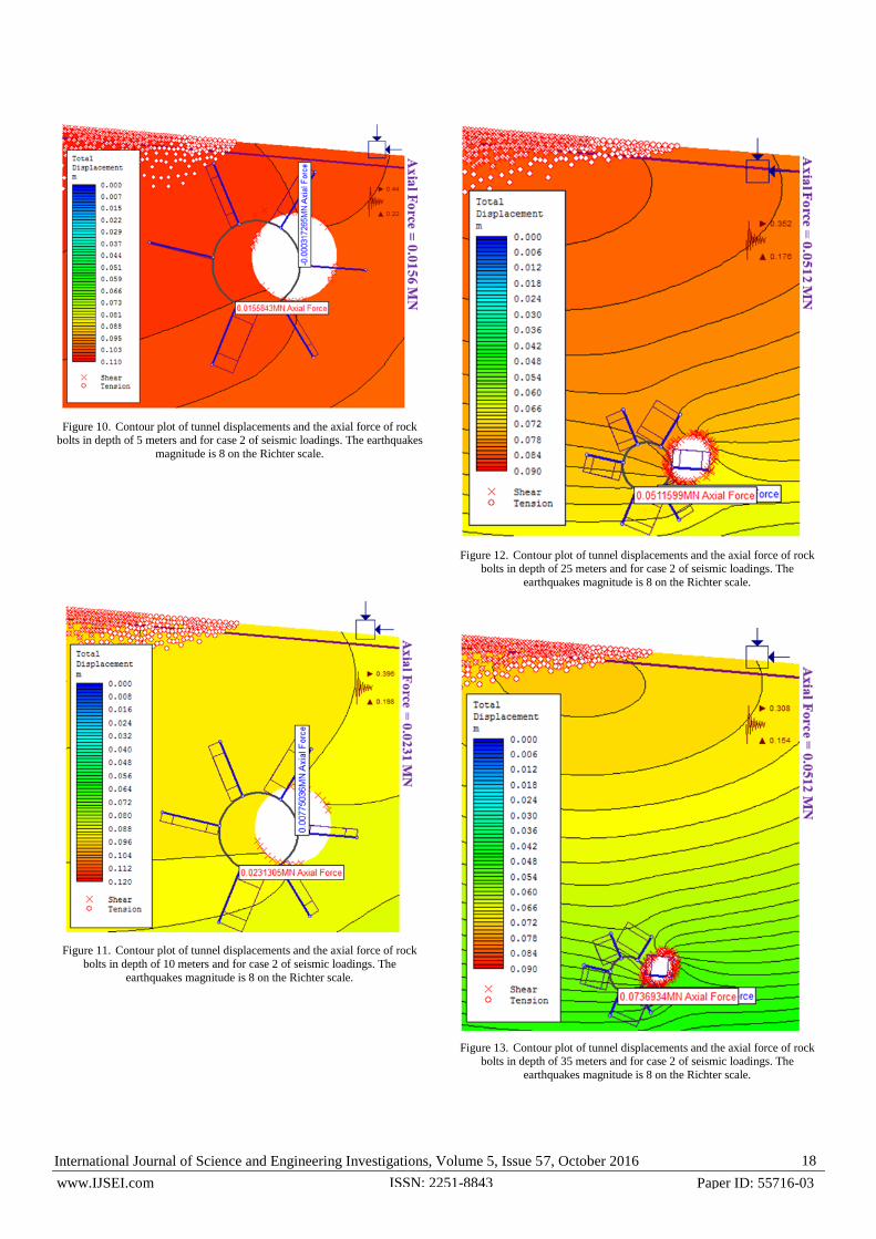
Figs. 10 to 13 show the results of displacements for tunnel with a diameter of 4 meters and in depths of 5, 10, 25 and 35 meters. As the mentioned figs. show, with increasing the tunnel depth, total displacements of tunnel reduced due to increasing the overburden and on the other hand, section deformation in tunnel and number of yielded elements around the tunnel increased with.
International Journal of Science and Engineering Investigations, Volume 5, Issue 57, October 2016 18
www.IJSEI.com Paper ID: 55716-03 ISSN: 2251-8843
Figure 10. Contour plot of tunnel displacements and the axial force of rock bolts in depth of 5 meters and for case 2 of seismic loadings. The earthquakes
magnitude is 8 on the Richter scale.
Figure 11. Contour plot of tunnel displacements and the axial force of rock
bolts in depth of 10 meters and for case 2 of seismic loadings. The
earthquakes magnitude is 8 on the Richter scale.
Figure 12. Contour plot of tunnel displacements and the axial force of rock
bolts in depth of 25 meters and for case 2 of seismic loadings. The
earthquakes magnitude is 8 on the Richter scale.
Figure 13. Contour plot of tunnel displacements and the axial force of rock bolts in depth of 35 meters and for case 2 of seismic loadings. The
earthquakes magnitude is 8 on the Richter scale.
International Journal of Science and Engineering Investigations, Volume 5, Issue 57, October 2016 19
www.IJSEI.com Paper ID: 55716-03 ISSN: 2251-8843
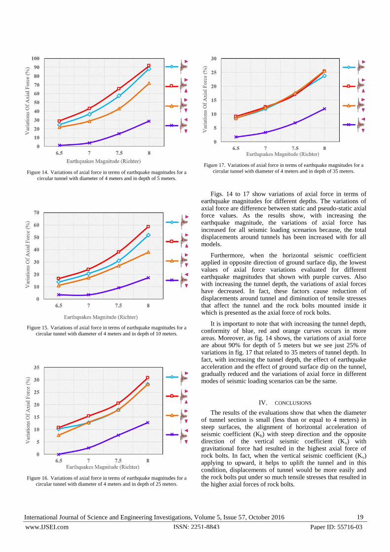
Figure 14. Variations of axial force in terms of earthquake magnitudes for a
circular tunnel with diameter of 4 meters and in depth of 5 meters.
Figure 15. Variations of axial force in terms of earthquake magnitudes for a
circular tunnel with diameter of 4 meters and in depth of 10 meters.
Figure 16. Variations of axial force in terms of earthquake magnitudes for a circular tunnel with diameter of 4 meters and in depth of 25 meters.
Figure 17. Variations of axial force in terms of earthquake magnitudes for a
circular tunnel with diameter of 4 meters and in depth of 35 meters.
Figs. 14 to 17 show variations of axial force in terms of earthquake magnitudes for different depths. The variations of axial force are difference between static and pseudo-static axial force values. As the results show, with increasing the earthquake magnitude, the variations of axial force has increased for all seismic loading scenarios because, the total displacements around tunnels has been increased with for all models.
Furthermore, when the horizontal seismic coefficient applied in opposite direction of ground surface dip, the lowest values of axial force variations evaluated for different earthquake magnitudes that shown with purple curves. Also with increasing the tunnel depth, the variations of axial forces have decreased. In fact, these factors cause reduction of displacements around tunnel and diminution of tensile stresses that affect the tunnel and the rock bolts mounted inside it which is presented as the axial force of rock bolts.
It is important to note that with increasing the tunnel depth, conformity of blue, red and orange curves occurs in more areas. Moreover, as fig. 14 shows, the variations of axial force are about 90% for depth of 5 meters but we see just 25% of variations in fig. 17 that related to 35 meters of tunnel depth. In fact, with increasing the tunnel depth, the effect of earthquake acceleration and the effect of ground surface dip on the tunnel, gradually reduced and the variations of axial force in different modes of seismic loading scenarios can be the same.
IV. CONCLUSIONS
The results of the evaluations show that when the diameter of tunnel section is small (less than or equal to 4 meters) in steep surfaces, the alignment of horizontal acceleration of seismic coefficient (Kh) with steep direction and the opposite direction of the vertical seismic coefficient (Kv) with gravitational force had resulted in the highest axial force of rock bolts. In fact, when the vertical seismic coefficient (Kv) applying to upward, it helps to uplift the tunnel and in this condition, displacements of tunnel would be more easily and the rock bolts put under so much tensile stresses that resulted in the higher axial forces of rock bolts.
International Journal of Science and Engineering Investigations, Volume 5, Issue 57, October 2016 20
www.IJSEI.com Paper ID: 55716-03 ISSN: 2251-8843
Furthermore, with increasing the tunnel depth, total displacements of tunnel reduced due to increasing the overburden which leads to section deformation in tunnel and number of yielded elements around the tunnel increased with.
Moreover, with increasing the earthquake magnitude, the variations of axial force have increased for all seismic loading scenarios and when the horizontal seismic coefficient applied in opposite direction of ground surface dip and also with increasing the tunnel depth, the variations of axial forces have decreased. Mentioned items shows the importance of the tunnel depth and diameter, tunnel movements and the impact of ground surface dip on the rock bolts that mounted in tunnel and finally the stability of tunnel. Each of these cases can lead to the destruction of a temporary tunnel supporting system or even to a complete closure of the tunnel cross. So, design engineers have to pay special attention in these cases to prevent structural damages and casualties in underground structures during the earthquake.
REFERENCES
[1] W.J. Gale, C. Mark, D.C. Oyler, and J. Chen, “Computer Simulation of Ground Behavior and Rock Bolt Interaction at Emerald Mine 2004”.
Proc. 23rd Intl. Conf. on Ground Control in Mining, Morgantown, WV, Morgantown, WV: West Virginia University, 27-34, 2004.
[2] A.C. Kliche, “Rock slope stability. Society for Mining Metallurgy”. USA, 1999.
[3] D.C. Wyllie, and C.W. Mah, “Rock slope engineering”, Fourth edition. London, Spon Press, 2004.
[4] T. Ramamurthy, “Engineering in rocks for slopes, foundation and tunnels”, Prentice Hall of India Private Limited, New Delhi, India, 2007.
[5] E. Hoek, and D.F. Wood, “Rock Support”, Mining Magazine, 159, 4, 282-287, 1988.
[6] J. Sulem, M. Panet, and A. Guenot, “An analytical solution for time-dependent displacements in a circular tunnel”, Int. J. Rock Mech. Mining Sci. Geomech, 24, 155-164, 1987.
[7] E. Hoek, “Practical Rock Engineering” <http://www.rocscience.com/hoek/ Practical Rock Engineering.asp>, 2007.
[8] T. Solak, “Ground behavior evaluation for tunnels in blocky rock masses”, Tunneling and Underground Space Technology, 24, 323-330, 2009.
[9] K. Kovári, “Tunneling in Squeezing Rock”, Tunnel, 5, 98, 12-31, 1998.
[10] E. Hoek, C. Carranza-Torres, and B. Corkum, “Hoek–Brown Failure Criterion-2002 Edition”. Rocscience, 2002.
[11] Rocscience, “A 2D finite element program for calculating stresses and estimating support around the underground excavations”. Geomechanics Software and Research. Rocscience Inc., Toronto, Ontario, Canada, 1999.
[12] A., Kaynia, “Personal communication”, 2011.