the eeducational eelectronic mmidi drum kkitthe numbers systems used in computer hardware and...
TRANSCRIPT

Empire Consumer Marketing Group89 Hitchcock Street • Holyoke, Massachusetts 01040
419-831-0943 • [email protected]
ECMG
EDUCATIONAL DESIGN SERIESEducational Electronic Kit
Using MicrocontrollersThe EEducational EElectronic MMIDI Drum KKit
Detailed Product Brochure

COPYRIGHT
Document Title:The Educational Electronic MIDI Drum KitDetailed Sales Brochure
Document Version:Version 3.0
Process/Revision Date:07/26/2002
The process described in this manual is furnished under a license agreement and is protected byUnited States copyright laws, international treaty provisions, and all other applicable nationallaws. No part of this publication may be reproduced, stored in a retrieval system, or transmittedin any form or any means other than the purchaser’s personal use without written permission ofECMG. The information contained in this manual is subject to change without notice.

Detailed Product Brochure Table of Contents:
I. Single Page Sales Brochure
II. Foreword
III. How You Can Benefit From This Product
IV. Sample Documentation
V. Ordering Information
VI. Drum Sound Selection Process
VII. Product Referral Program
PAGE 1

TOPICS COVERED:ELECTRICAL ENGINEERING• The MIDI protocol that communicates with the soundcard on aPC. Also included will be a general explanation of how serial com-munication works between peripherals and the PC and betweenPC's.
• The microcontroller that converts the data received from the 8drum sensors into the MIDI protocol. Also included will be a dis-cussion about other applications that these microcontrollers areused in and an explanation of how these microcontrollers fit intothe world of electrical engineering and computer chips in general.
• A flow chart explanation of the software that is programmed intothe microcontroller. Also included will be an explanation of whatcomputer languages are used to program microcontrollers andhow the overall process works.
• How to properly condition the inputs from the sensors to givethe microcontroller a signal that it can process correctly.
• An explanation on how crystal oscillators work and why they areneeded in electronic devices.
• An explanation of how the drum sensors (i.e. peizo sensors)work and why they produce a signal capable of being processedby a microcontroller when they are struck.
MATH AND PHYSICS• Number systems in general and a more in-depth discussion ofthe numbers systems used in computer hardware and program-ming.
• An explanation of the Math needed to calculate the values of thevarious components used in this electronics kit as an input to, anoutput of, and power source to the micro controller.
• An explanation of the Physics behind the various componentsused in this electronics kit and why they work the way they do.
Empire Consumer Marketing Group
89 Hitchcock Street • Holyoke, Massachusetts 01040419-831-0943 • [email protected]
ECMG EDUCATIONAL DESIGN SERIESEducational Electronic Hobby Kit
Using MicrocontrollersTThhee MMIIDDII 88-PPiieeccee EElleeccttrroonniicc DDrruummKKiitt
BENEFITS:This educational electronic hobby kit institutes the most currentnational and state high school learning standards in the Scienceand Technology/Engineering Curriculum Frameworks. This edu-cational electronic drum kit is based on actual project basedcourses taken on the university level in microcontrollers. Itallows parents of electronic enthusiasts and electronic hobbyiststhemselves, a way of seeing the future potential in a careerdesigning electronic devices using microcontrollers, and to spurtheir interest in further education in the various fields of electri-cal engineering.
Microcontrollers are found in a multitude of applications in theautomotive, consumer communications, office automation andindustrial control markets. For example, a modern car may have50 or more microcontrollers controlling anti-lock brakes, keylessentry, air bags, burglar alarm systems and various vital enginefunctions. On the other hand a home is likely to have at least 30and perhaps as many as 200 microcontrollers embedded in suchpopular household items as the washing machine and clothesdryer, security system, refrigerator, microwave oven, various electronic games, smoke detectors, and not to mention per-sonal computers and their peripherals.
The instructional documentation contained in this electronics kit steps through the design process, and explains how alge-bra and physics, with the aid of software, are used in the design process to create an eight piece MIDI drum set that eas-ily attaches to the gameport of a standard soundcard on almost any desktop PC. Assembly of the kit requires no solder-ing and the drum sounds created by the microcontroller can be customized to include eight drum and cymbal sounds fromthe current total of 48 drum and cymbal sounds created and recognized by the soundcard on a desktop PC.
KIT INCLUDES:1. CD-ROM containing the software needed to play the drum
sounds on your computer and the instructional documentation.
2. One - gameport cable used to connect the electronics kit tothe soundcard of a PC.
3. One - 5V DC power supply used to power the electronics kit.
4. Directions on how to assemble the electronics kit.
5. All the parts necessary to assemble the electronics kit.• Breadboard (1)• Resistors (20)• Capacitors (5)• Diodes (9)• Opto-Isolator (1)• DB15 Gameport Connector (1)• 4Mhz Crystal Oscillator (1)• Peizo Sensors (i.e. Drum Pads) (8)• Jumper wire to connect the components together.• Drum sticks (2)• Pre-programmed PIC 16F877 Microcontroller (1)
The only component not supplied by this kit is a desktop PC with a soundcard.
“It is truly amaz-ing how real thedrum soundsare coming fromthe speakers ofthe sound-card...”
“I really liked theability to person-alize the drum-set to includeonly the soundsthat I wanted toinclude in my kit.It kept my inter-est throughoutthe building ofthe kit and Ilearned a greatdeal...”
ORDERING AND PRICING INFORMATION:Our Educational Design Series electronic drum kit can bepurchased by visiting our website at www.ecmg.net or bycalling us directly at 419-831-0943.
Pricing is as follows:
1 - 10 Kits: $199.99 $149 SALE PRICE10+ Kits: $189.99 $139 SALE PRICE
“I wasimpressed athow easy this kitwas to assem-ble and alsohow much Iactually learnedabout the overalldesign processitself...”

Detailed Product Brochure
Foreword
The purpose of this detailed product brochure is to demonstrate the value of our 8Piece MIDI Drum Kit. Every kit we distribute contains a comprehensive User Guideand Reference Manual (UGRM) that is heads and shoulders above the competition.Our UGRM not only provides in-depth assembly directions along with step-by-stepcolor photos, but as a bonus we have included the actual design process method-ology used to create this kit. We hope you will find the background information anddesign process methodology as interesting as assembling the kit itself. Another dis-tinct advantage of our 8 Piece MIDI Drum Kit is that most of the electronic kits onthe market today use antiquated parts and technologies; whereas our kits use themost current parts and advances in the electronic design process.
PAGE 3

Detailed Product Brochure
Prospective Customers
This product can be used and applied in various ways depending on the type of cus-tomer you might be. Click on the links below to see how this electronics kit can specif-ically benefit you.
Educators
Parents
Students
Musicians
Hobbyists
The sample Instructional Documentation includes:
1. The Title page2. The Contents page3. Overview4. Introduction5. Chapter One: The Design Process: Identify the need or problem.6. Chapter Two: The Design Process: Research the need or problem.7. Chapter Five: Construct a prototype.
a. First two pages of the assembly directions.
This sample documentation should give you a good idea as to the quality of this prod-uct and the instructional documentation included with it. It should also give you an ideaof the flow and structure of the instructional documentation, and the ease and depth towhich it explains the design process for microcontrolled electronic devices. Additionally,it gives a sample of the background information about basic electrical concepts and,which shows what the background information is like and how comprehensive it is.
PAGE 4

Detailed Product Brochure Educators
This product is based on actual project based courses taught at the university level. This“8 Piece MIDI Drum Kit” is a great teaching tool for educators because it teaches aboutbasic electrical and electronic concepts, the most current design process for microcon-trolled electronic devices, and modern musical composition through the use of the MIDIprotocol.
Educators can use this electronics kit to spark the natural interests and curiosity of theirstudents inspiring them to seek further education in the areas of Science, Engineering,and possibly Musical Composition. This electronics kit will demonstrate much of what iscurrently possible in the fields of Science and Engineering and how an electronic devicedesign gets from point A to point Z, as well as the various tools used in the designprocess.
University science departments all over the United States are moving toward a moreproject based curriculum. Because of this, Junior High and High schools that areattempting to respond to these changes will seek to supplement their school curriculumwith these types of project based programs. This product allows the teacher to focus onteaching without having to be an expert in the field of electrical and electronic design.The instructional documentation includes everything that you will need to teach aboutthe design process for this electronics kit including background electrical component andconcept information as well as very detailed assembly directions.
Our product requires no soldering of parts, and it can be taken apart, reassembled, andreused for use in other classes. This electronics kit has much relevance for educators intoday's marketplace. We at ECMG believe that most of the value of this product is con-tained in content of the instructional documentation and assembly directions. With thisin mind ECMG has included in our product brochure, samples of the instructional docu-mentation and assembly directions to demonstrate the quality of this product and thedocumentation that accompanies it.
[ Table of Contents Sample Documentation How to Order ]
PAGE 5

Detailed Product Brochure Parents
This “8 Piece MIDI Drum Kit” can be used as a great teaching tool for parents who wantto supplement their child's education with a project based program that is relevant,interesting and fun to both build and use.
Parents today find themselves in a peculiar situation when it comes to the education oftheir children, especially those whose children are attending Junior/High School andpreparing for College. School curriculums of the past, though slowly changing for thebetter have at times inadequately educated students in the areas of Math and Science.Because of this, parents find themselves searching for ways to supplement the curricu-lum outside of school. It was with you in mind that ECMG created this educational elec-tronic drum kit.
Parents can use this product to enhance their child's education by demonstrating thepossibilities using Math and Science in electronic device design, by constructing this “8Piece MIDI Electronic Drum Kit”.
Building our product is also a great way to spend quality time with your child by con-structing a state of the art electronic device that has much relevance in the areas ofmusic, electronics and engineering. It is a great way to spur a child’s curiosity in Math,Science, and Engineering. And it will help to prepare them for the project based cur-riculums currently being adopted by science departments in colleges all across theUnited States.
The need for math and science education among the junior high, high school and uni-versity level is increasing rapidly. University science departments are rapidly movingtoward a project based curriculum focused on problem solving skills, and the designprocess.
Much of the value of this product is contained in the instructional documentation andassembly directions. With this in mind, ECMG has included in this sales brochure sam-ples of the instructional documentation and assembly directions to show the quality ofthis product and the documentation that accompanies it.
[ Table of Contents Sample Documentation How to Order ]
PAGE 7

Detailed Product Brochure Students
This product is ideal for students who attend or are looking to attend an electrical and/orcomputer engineering program. This product is based on actual project based coursestaught at the college level. With this product you will learn the steps that are taken inthe design process to create a realistic sounding “8 piece MIDI drum kit.” The stepstaught in this instructional documentation can be applied to the design of many of theelectronic devices on the market today.
This product gives you all the pieces to the puzzle that are needed to understand theoverall design process for microcontrolled electronic devices, and to understand thedesign process for this electronic drum kit in particular. Where as the college coursewould teach you specifically how to program the microcontroller by designing an elec-tronic device in the lab. This product gives you the outlining structure to the electronicdevice design process without requiring you to know how to program the microcontrollerchip. We give you a pre-programmed microcontroller which has 8 sounds programmedinto the chip that you select.
Our product is basically training wheels for the higher level programming courses taughtat the college engineering level. This kit’s instructional documentation can give you agreat head start toward college by teaching you the steps involved in the design processfor microcontrolled electronic devices and how the product works along with backgroundinformation describing the various electrical and electronic components used in this elec-tronic drum kit.
This product can be used to play and record realistic sounding drum, and other uniquemusical sounds using the MIDI protocol. The MIDI protocol can be used in a variety ofways to both play, and compose music. The standard desktop PC with MIDI softwareavailable from the internet, can be used to compose all musical genres including classi-cal music compositions. Complete symphonies can be composed by understanding howthe MIDI protocol works and knowledgeable use of the various software packages avail-able to compose music using the MIDI protocol.
This product can be used to form a base of knowledge from which you can furtherexplore in more detail the topics outlined in the instructional documentation includedwith this drum kit. In the User Guide and Reference Manual, there are many links to getadditional information about the various topics discussed in the documentation.
Much of the value of this product is contained in the instructional documentation andassembly directions. With this in mind, ECMG has included in this sales brochure sam-ples of the instructional documentation and assembly directions to show the quality ofthis product and the documentation that accompanies it.
[ Table of Contents Sample Documentation How To Order ]
PAGE 9

Detailed Product Brochure Musician
This product can be used both by musicians who do not know how the MIDI protocolworks, and by those who do. Both can gain insight into the MIDI protocol workings fromthe fundamental hardware and software perspective. This can add to your abilities whenit comes to playing and composing MIDI sound files.
If, as a musician you are already familiar with the MIDI protocol, and already have asynthesizer that you are using, and do not require the soundcard of the standard PC toplay the MIDI protocol, then the standard MIDI connector can be substituted in place ofthe (DB15) Gameport connector used to connect to the soundcard. This way you canconnect this instrument into your already existing MIDI chain to the synthesizer of yourchoice.
There are currently 61 percussion instrument sounds to choose from for this drum kit,of which 8 can be chosen by you to be pre-programmed into the microchip. This wayyou can create a customized percussion instrument to suit your desires. The 61 percus-sion MIDI sound files are contained on our website and can be accessed by ClickingHere.
Much of the value of this product is contained in the instructional documentation andassembly directions. With this in mind, ECMG has included in this sales brochure sam-ples of the instructional documentation and assembly directions to show the quality ofthis product and the documentation that accompanies it.
[ Table of Contents Sample Documentation How to Order ]
PAGE 11

Detailed Product Brochure Hobbyists
If you are a hobbyists or an electronic kit enthusiasts then this product is for you. Unlikeother electronic kits on the market today, this electronic kit gives you information aboutcomprehensive product functioning, the design process used to create the product, andbackground information about the various electrical and electronic components used inthe design.
Many of the electronic kits on the market today do not include very detailed assemblydirections. ECMG took many of the inadequacies perceived in the general electronic kitmarket and capitalized on them creating comprehensive instructional documentationand detailed assembly directions that set this product apart from the competition. Ourassembly directions included with this kit contain high resolution digital images for eachstep in the assembly process along with detailed instructions explaining each step.
The product not only teaches about electronics and electronic device design, but canalso be used to create a realistic sounding musical instrument. This product can be usedto create a base of knowledge about the electronic device design process, how com-puters and peripherals communicate, and how modern musical instruments aredesigned. The instructional documentation contains many links to additional informa-tion on the internet that can be used to further expand your knowledge about the par-ticular topics covered in the instructional documentation included with this product.
You can use this product to learn about the MIDI protocol and its many uses in the worldof music. The MIDI protocol has recently become even more popular because today’scurrent soundcard manufacturers are including sampled instrument sounds on theirsoundcard chips, which results in realistic sounding instruments. Because of this, gam-ing software developers and website designers are also using the MIDI protocol to playtheir sounds instead of normally recorded sound files. The MIDI protocol is being adapt-ed in this way because of the sound file compression that is available as compared tothe normally recorded sound files such as the .wav sound file format.
Much of the value of this product is contained in the instructional documentation andassembly directions. With this in mind, ECMG has included in this sales brochure sam-ples of the instructional documentation and assembly directions to show the quality ofthis product and the documentation that accompanies it.
[ Table of Contents Sample Documentation How to Order ]
PAGE 13

Empire Consumer Marketing Group89 Hitchcock Street • Holyoke, Massachusetts 01040
419-831-0943 • [email protected]
ECMG
EDUCATIONAL DESIGN SERIESEducational Electronic Kit
Using MicrocontrollersThe EEducational EElectronic MMIDI DrumKit
User Guide and Reference Manual
SAMPLE DOCUMENTATIONThis is not the complete Reference Manual documentation. This is a small sample to show thequality of the documentation that is contained with this electronic drum kit. In the complete versionof the Reference Manual, the hypertext links underlined in black are links to further information toa particular topic. This sample documentation does not includes chapters 3, 4, most of 5, 6, 7 and8. In place of chapters 3 and 4, an outline of the topics discussed is included for each chapter. Anoutline of chapters 6, 7 and 8 is not included in this sample documentation, these steps in thedesign process were not the primary focus of this product and therefore these chapters are lightlycovered.

COPYRIGHT
Document Title:Educational Design SeriesEducation Electronic Hobby Kit Using MicrocontrollersThe MIDI 8-Piece Electronic Drum KitUser Guide and Reference Manual
Document Version:Version 4.0
Process/Revision Date:10/27/2001
The process described in this manual is furnished under a license agreement and is protected byUnited States copyright laws, international treaty provisions, and all other applicable nationallaws. No part of this publication may be reproduced, stored in a retrieval system, or transmittedin any form or any means other than the purchaser’s personal use without written permission ofECMG. The information contained in this manual is subject to change without notice.

TRADEMARKS
All terms mentioned in this manual that are known to be trademarks or registered trademarkshave been appropriately noted. ECMG cannot attest to any accuracy of this information. Use of aterm in this manual should not be regarded as affecting the validity of any trademark or regis-tered trademark.

CONTENTS
Overview
Introduction
Chapter One
Chapter Two
Chapter Three
Chapter Four
Chapter Five
The Relationship Among Science, Engineering and Technology
The Design Process: Identify the need or problem
Preface
The Design Process: Research the need or problem
The Design Process: Develop possible solutions
The Design Process: Select the best possible solution
The Design Process: Construct a prototype
Chapter Six The Design Process: Test and evaluate the prototype
Chapter Seven The Design Process: Start the manufacturing process
Chapter Eight The Design Process: Between product cycles revaluate prior design andredesign if necessary
Bibliography
OVERVIEWThere are two different approaches one can take when building our electronic kits:
· One could chronologically proceed through our documentation one chapter at a time, finally constructing the prototype in STEP 5 of our design process.
· Or, one could proceed directly to STEP 5, essentially bypassing STEPS 1-4, and godirectly to constructing a working prototype by simply following the assembly directions contained in Chapter 5. Then starting from Chapter 1, read the rest of the chapters (STEPS 1-4) to find out exactly how our electronic kit works, and how it was designed.
The purpose of our electronic kits is to explain the steps involved in the overall design process formicrocontrolled electronic devices culminating in the construction of a working prototype in Step 5of the overall design process. Our electronic kits should spur the interest of students and hobby-ists of all ages, especially those eager to pursue further education or even a career in electricaland electronic engineering.
Our educational design series products can be used by educational providers to enhance the stu-dent's classroom experience in a variety of ways. For instance, those teaching on a Jr. High/HighSchool/College level could easily use this kit to demonstrate the overall design process for manyof the electronic devices on the market today. In an elementary school environment, our kit canbe used as an electronic musical tool connected to the classroom computer that hopefully willinspire the natural inquisitiveness, curiosity of young minds. This electronic kit can even be usedby parents to enhance their child's education at home, spending quality time together by goingstep-by-step through our design and assembly process.
The person who successfully goes through the design process and assembly of one of our kits,besides learning about the design process for microcontrollers as it currently exists, will also learnabout the state of music composition in the 21st century by learning about the General MIDI pro-tocol standard. It’s our companies firm belief that had Beethoven, lived in this century, he wouldprobably be using the MIDI standard to aid in the writing and composition of his orchestra stylemusic. Both the electronic hobbyists, and the music enthusiast can use this kit to insight into thedesign process for micro controlled musical instruments implementing the MIDI protocol standard.
PAGE 1

INTRODUCTION
Science Engineering
Technology
The Relationship Among Science, Engineering, and Technology
Science seeksto understandthe naturalworld, and oftenneeds new toolsto help discoverthe answers.
Engineers usescientificdiscoveries todesign productsand processesthat meetsociety's needs.
Technologies (products and processes) are theresults of engineered designs. They are created bytechnicians to solve societal needs and wants.
Engineering, Science and TechnologyUnderstanding the relationship among science, engineering, and technology in the design processof electronic devices is critical to understand how these factors will effect the design process in thefuture. Engineers use both scientific discoveries about the world around them, and current tech-nologies to create new products and processes that meet society's most current needs anddemands. These societal needs, from the Electrical Engineering perspective, cover a wide array oftopic areas and industries. Electrical Engineers seek to find solutions to problems in such topicareas as healthcare, automotive, flight, and communications just to name a few. Most of thesesolutions require microcontrolled electronic devices to solve a particular problem.
The overall market for microcontrollers is 15 times larger than that of the microprocessor (i.e. per-sonal computer) market and is expected to increase exponentially in the next few years as every-day electronic devices begin to communicate with each other in new ways. Currently microcon-trollers are used in most of the electronic devices on the market today. The understanding ofmicrocontrollers is critical to the understanding of the electronic device design process as it cur-rently exists in the 21st Century. The need for people in society to design these types of electron-ic devices will also increase for the foreseeable future. Currently there is a high demand for elec-trical engineers in the United States. The more society relies on electronic devices to assist in theproductivity of their daily lives, the more workers in these fields will be needed in the future.
Engineers apply the theories and principles of science and mathematics to research and developeconomical solutions to technical problems. Their work is the link between scientific discoveriesand commercial applications. Engineers design products, machinery to build those products, fac-
PAGE 2

INTRODUCTIONtories in which those products are made, and the systems that ensure the quality of the product,and efficiency of the workforce and manufacturing process. Engineers design, plan, and supervisethe construction of buildings, highways, and transit systems. They develop and implementimproved ways to extract, process, and use raw materials such as petroleum and natural gas. Theydevelop new materials that both improve the performance of products, and help implementadvances in technology. They harness the power of the Sun, the Earth, atoms, and electricity foruse in supplying the Nation's power needs, and they create millions of products using power.Engineering knowledge is applied in improving many things, including the quality of health care, anations security and defense, the safety of food products, and the efficient operation of financialsystems.
Engineers consider many factors when developing a new product. For example, in developing anindustrial robot, engineers determine precisely what function the robot needs to perform; designand test the robot's components; fit the components together in an integrated plan; and evaluatethe design's overall effectiveness, cost, reliability, and safety. This process applies to many differ-ent products, such as chemicals, computers, gas turbines, helicopters, and toys, just to name afew.
Engineers use computers to produce and analyze designs; to simulate and test how machines,structures, or systems operate; and to generate specifications for parts. Engineers also use com-puters to monitor product quality and control process efficiency. They spend a great deal of timewriting reports and consulting with other engineers, as complex projects often require an interdis-ciplinary team of engineers to complete.
Educational requirements to become an engineer:A bachelor's degree in engineering is generally required for entry-level engineering jobs. Collegegraduates with a degree in a physical science or mathematics may occasionally qualify for someengineering jobs, especially those specialties in high demand. Most engineering degrees are grant-ed in electrical, mechanical, or civil engineering. However, engineers trained in one branch maywork in related branches. For example, many aerospace engineers have training in mechanicalengineering. This flexibility allows employers to meet staffing needs in new technologies and spe-cialties in which engineers are in short supply. It also allows engineers to shift to fields with bet-ter employment prospects, or to ones that match their interests more closely.
In addition to the standard engineering degree, many colleges offer degrees in engineering tech-nology which are offered as either 2- or 4-year programs. These programs prepare students forpractical design and production work, rather than jobs that require more theoretical and scientificknowledge. Graduates of 4-year technology programs may get jobs similar to those obtained bygraduates with a bachelor's degree in engineering. Some employers regard technology programgraduates as having skills between those of a technician and an engineer.
About 320 colleges and universities offer bachelor degree programs in engineering that are accred-ited by the Accreditation Board for Engineering and Technology (ABET), and about 250 collegesoffer accredited bachelor's degree programs in engineering technology. ABET accreditation is basedon an examination of an engineering program's student achievement, program improvement, fac-ulty, curricular content, facilities, and institutional commitment. Although most institutions offerprograms in the major branches of engineering, only a few offer some of the smaller specialties.Also, programs of the same title may vary in content. For example, some programs emphasize
PAGE 3
INTRODUCTIONindustrial practices preparing students for a job in industry, whereas others are more theoreticaland better suited for students preparing for graduate work. Therefore, students should investigatecurricula and check accreditations carefully before selecting a college. Admissions requirements forundergraduate engineering schools include a solid background in mathematics (algebra, geometry,trigonometry, and calculus), sciences (biology, chemistry, and physics), and courses in English,social studies, humanities, and computers.
Bachelor's degree programs in engineering are typically designed to last 4 years, but many stu-dents find that it takes between 4 and 5 years to complete their studies. In a typical 4-year col-lege curriculum, the first 2 years are spent studying mathematics, basic sciences, introductoryengineering, humanities, and social sciences. In the last 2 years, most courses are in engineering,usually with a concentration in one branch. For example, the last 2 years of an aerospace programmight include such courses as fluid mechanics, heat transfer, applied aerodynamics, analyticalmechanics, flight vehicle design, trajectory dynamics, and aerospace propulsion systems. Someprograms offer a general engineering curriculum; students then specialize in graduate school or onthe job.
Some engineering schools and 2-year colleges have agreements whereby the 2-year college pro-vides the initial engineering education; and the engineering school automatically admits studentsfor their last 2 years. Some colleges and universities offer 5-year master's degree programs. Some5- or even 6-year cooperative plans combine classroom study and practical work, permitting stu-dents to gain valuable experience and finance part of their education.
Engineers should be creative, inquisitive, analytical, and detail-oriented. They should be able towork as part of a team and be able to communicate well, both orally and in writing. Beginningengineering graduates usually work under the supervision of experienced engineers, and in largecompanies, may also receive formal classroom or seminar-type training. As new engineers gainknowledge and experience, they are assigned more difficult projects with greater independence todevelop designs, solve problems, and make decisions. Engineers may advance to become techni-cal specialists or supervise a staff or team of engineers and technicians. Some eventually becomeengineering managers, or enter other managerial positions or sales jobs.
Technology is the compilation of all the created products and processes that engineers havedesigned over time. The new products and processes created by engineers using technology seekto make society more efficient and productive. By making people in society more efficient and pro-ductive, more of the problems that society confronts can be solved or at least diminished in capac-ity, especially those problems in society which can be solved through the use of science, engi-neering and technology.
Technology in an economic sense, is the relationship between inputs and outputs in a laborprocess. And the labor process is defined as the transformation of our natural surroundings usinghuman labor with the intention of producing something useful. The technical change createdthrough the use of technology can take on two different forms. The first form is laborsaving tech-nical change, and the second form is capital saving technical change. Labor saving technicalchange gives us the ability to produce more stuff, ect. with less labor. And capital saving technicalchange gives us the ability to produce more things, ect with less capital resources required to pro-duce the same amount of work or product. These technical changes increase the profit rate foremployers, which usually generate higher wages for employees thereby raising the standard of liv-
PAGE 4

INTRODUCTIONing of all the people involved with creating and using these technical changes. The technology usedin the design of electronic devices using microcontrollers has changed drastically over the last 10years or so. Both new science, and the use of current technologies are creating a process that ismore streamlined and easier for small design teams to produce complex designs cheaply. The syn-ergy of high speed computing along with high quality simulation software packages makes theoverall electronic device design process easier for one person to understand and command. Thisexplosion in circuit design software and microcontroller programming software has made the pro-totyping of potential electronic devices much cheaper and has reduced, shortened the time it takesfor electronic devices to make it from the concept stage of development to the production stageof development.
Science, from the microcontroller electronic design perspective seeks to understand the naturalworld in order to discover new ways to make electronic components smaller, faster and consumeless power. These new discoveries of science are then used in the research and development phaseof product development to produce products that use the newfound scientific discoveries.Engineers then take these new electrical components and create new, more efficient productsusing this new technology. Scientists in electrical engineering discover new fundamental ways bywhich electrical components function. These discoveries are then used to produce products thatare smaller and more efficient than the same products made through an older method.
This process of finding new scientific discoveries and creating new products based on these newdiscoveries, is one that has existed for over 100 years in the electrical industry. The relationshipamong science, technology and engineering is often not easy to distinguish, and the three areasoften, frequently overlap. This overlapping relationship often causes a blurring of the lines betweenscience, engineering, and the technological products that are created through their efforts.
Some of the products created by using current technology help the engineering process becomemore efficient and productive. In the last four years software has been developed which aids thehardware development process by completely simulating hardware and software design on thepersonal computer (PC) prior to constructing a prototype and starting the manufacturing process.This drastically reduces the development time for products and has also enabled the developmentof complex products with relatively few engineering design team members. Software is currentlybeing released that automatically creates assembly language code for a particular chip from thesimulation block diagrams created in the conceptual stages of the design process. This automaticcode creation, dramatically reduces the labor involved in the electronic device design process.Although it may be advertised as automatic code creation, one still has to be astute with both thehigher level C language and the lower level assembly language that is specific to the type of com-puter chips used in a design, to properly debug the code in order to make the electronic devicework correctly. It does not take the process of code creation totally out of the hands of the elec-tronic device designer, but can with some designs convert system design block diagrams createdin design simulation software into useable assembly language code. The labor process involvedwith code creation is diminished but not eliminated. Figure 1 on the next page shows a flow chartof a microcontrolled electronic device design process from the perspective of software develop-ment tools used in the design process.
The process involved on the software development side of electronic circuit design uses the soft-ware packages listed in figure 1 during different stages of the design process. These particular soft-ware packages were used in the design of this electronic kit. These software packages listed in
PAGE 5

INTRODUCTIONfigure 1 are by no means the only packages available on the market today, but they do control thelargest market share among electronic device designers and are setting the future trends in soft-ware development which streamline the electronic circuit design process.
New synergistic develop-ments between softwareimplementation and com-puting power are makingthe design process forelectronic devices easierand are resulting in adecreased time to marketfor the design of electron-ic devices. One designengineer using this newtechnology can accom-plish in the same amountof time what used to takea design team of severalengineers to accomplish.These recent computingand software develop-ments and the future ofelectronic device designare moving in the direc-tion of automatic codecreation. In the nearfuture there will be higherquality software that auto-matically takes a designfrom the block diagramrepresentation of the sys-tem, generates the codenecessary to implementthat design on a program-mable computer chip, andcreates the circuit diagramneeded to prototype theelectronic device automat-ically.
Figure 1Mathworks, the creators of MatlabTM and SimulinkTM a major provider of software and hardwaresimulation software, is currently moving in this direction and already has software that can gener-ate assembly language code from block diagram representations. Another major hardware simu-lation software company Protel Inc. has recently acquired Tasking Inc. to bridge the gap betweensoftware development for the programming of computer chips, and the development of the elec-tronic circuit boards where the chips reside. There is a whole host of mergers, acquisitions andpartnerships occurring in this area as chip manufactures and electronic design simulation software
MathworksMPLAB/Simulinkand the
StateflowCoder Blockset
MPLAB orother chip
manufacturer'sprogramming
software
ICD-ChipProgrammmer
orChip
EvaluationBoard
Protel-Orcad/Spiceor Autocad
Used to createschematic
diagram forelectronic
circuit
Constructed Electronic Prototype orManufactured Electronic Device
MATLAB's Real Time Workshopcompiles block diagrams andstateflow diagrams created inSimulink and translates that intoANSI C code. This code is thenused in the next process.
The MPLAB Compiler translatesthe ANSI C code created by thepreceding process into targetassembly code for the particularmicrochip chosen. For ourdesign we used the PIC16F877from Microchip.
The ICD module is used in thisdesign to speed developementtime. With this module byMicrochip, assembly languagecode can easiliy be debuggedand tested by plugging the ICDinto the prototype circuit andevaluating the results in realtime. This can all beaccomplished while adjustingthe code in MPLAB andreprogramming the ICD inorderto perfect the code creatingprocess.
The schematic is used as areference to construct aprototype or software packagessuch as Orcad are used tocreate the gerber files used byrobotic printed circuit boardmanufacturers to create a finalproduct.
Various Software Tools Currently used in the Design Process for Electronic Devices(These are but some of the more prveleant software tools used in the design of microcontroled electronic devices.)
Two paths are takensimultaneously
throughout the designprocess.
PAGE 6

providers' team up to create an all-in-one solution for the development of electronic devicedesigns. Currently, there are many software development providers that aid in the design of elec-tronic devices for the various stages in the design process. Some of major providers of simulationand development software are as follows: Mathworks, Protel, Orcad, Microchip, Motorola, andTexas Instruments.
Together science, engineering and technology are working to make the design process easier sothat more people in our society may take part in the technical revolutions of the 21st Century. Thiscooperation among science, engineering and technology allows an engineer to focus on producingsolutions to problems rather than being preoccupied with the tangential processes involved withthe solution.
INTRODUCTION PAGE 7

Step 1Identifiy the Need
or Problem
Step 2Research the Need
or Problem
Step 3Develop Possible
Solution(s)
Step 4Select the Best
Possible Solution(s)
Step 5Construct
a Prototype
Step 8Between Product Cycles
Revaluate prior design andRedesign if necessary
Step 7Start the
Manufacturing Process
Step 6Test and Evaluate
the Solution(s)
Steps 1of the
Engineering Design Processfor
MicrocontrolledElectronic Devices
CHAPTER ONE The Design Process: Identify the need or problemPAGE 8
STEP 1
The EngineeringDesign Process
for MicrocontrolledElectronic Devices

CHAPTER ONEStep 1. Identify the NeedThe design process begins when there is a need perceived. Wherever there are people, there areproblems requiring solutions. In some cases the designer may have to invent a product. An exam-ple might be an electronic healthcare device that can detect cancer at its earliest stages, or an elec-tronic device that helps to eliminate traffic accidents. At other times the designer may change anexisting design. For example, the brakes of an automobile were redesigned into anti-lock brakes outof the need to stop more quickly on slippery surfaces. This particular need had existed for manyyears but the technology at the time was not advanced enough to produce anti-lock breaks thatwere safe, reliable and economically practical. In this specific case, designers improved upon anexisting product to make the product work better.
From computer chips that process millions of instructions every second, to radar systems that detectweather patterns days in advance, electrical and electronic engineers are responsible for a widerange of technologies. Electrical and electronics engineers design, develop, test, and supervise themanufacturing of electrical and electronic equipment. Some of this equipment includes power gen-erating, controlling, and transmitting devices used by electric utilities; electric motors, machinerycontrols, lighting and wiring in buildings, automobiles and aircraft; and in radar and navigation sys-tems, computer and office equipment, and broadcast and communications systems.
Electrical engineers specialize in different areas of the industry such as power generation, trans-mission, and distribution; communications; computer electronics; and electrical equipment manu-facturing-or any subdivision of these areas-industrial robot control systems, or aviation electronics,for example. Electrical engineers design new products, write performance requirements, and devel-op maintenance schedules. They also test equipment, solve operating problems, and estimate thetime and cost of engineering projects.
Electrical engineers held about 357,000 jobs in 1998, making it the largest branch of engineering.Most jobs were in engineering and business consulting firms, government agencies, and manufac-turers of electrical and electronic equipment, industrial machinery, and professional and scientificinstruments. Communications and utilities firms, manufacturers of aircraft and guided missiles, andcomputer and data processing services firms accounted for most of the remaining jobs. California,Texas, New York, and New Jersey-states with many large electronics firms-employ over one-third ofall electrical and electronics engineers.
Electrical engineering graduates should have favorable job opportunities long into the future. Thenumber of job openings resulting from employment growth, and the need to replace electrical engi-neers who transfer to other occupations or leave the labor force is expected to be in rough balancewith the supply of graduates. Employment of electrical and electronics engineers is expected to growbetween 21-35% for all engineering occupational categories through 2008, which is faster thanaverage.
Projected job growth stems largely from increased demand for electrical and electronic products, includ-ing computers and communications equipment. The need for electronics manufacturers to invest heav-ily in research and development in order to remain competitive and maintain their scientific edge willprovide openings for graduates who have learned the latest technologies. Opportunities for electronicsengineers in defense-related firms should improve as aircraft and weapon systems are upgraded withimproved navigation, control, guidance, and targeting systems. However, job growth is expected to befastest in service industries, particularly consulting firms that provide electronic engineering expertise.
The Design Process: Identify the need or problemPAGE 9

Median annual earnings of electrical engineers were $62,660 in 1998. The middle 50 percentearned between $47,080 and $80,160. The lowest 10 percent earned less than $38,470 and thehighest 10 percent earned more than $91,490. Median annual earnings in the industries employ-ing the largest numbers of electrical engineers in 1997 were:
Federal government : $68,000Computer and office equipment: $67,100Electronic components and accessories: $59,900Communications equipment: $59,400Engineering and architectural services: $58,900
According to a 1999 salary survey by the National Association of Colleges and Employers, bache-lor's degree candidates in electrical and electronics engineering received starting offers averagingabout $45,200 a year; master's degree candidates, $57,200; and Ph.D. candidates, $70,800.
The need to produce this educational electronic kit arose from the recent increased demand forelectrical engineers in the marketplace. The need to encourage junior high and high school stu-dents to pursue further education at the collegiate level in electrical engineering has become anever-important one. The demand for labor in this field has grown dramatically over the past fewyears and is expected to continue for the foreseeable future. At the same time school curriculumstandards are changing to further promote engineering and technology on the junior high and highschool level.
Also there is a growing trend to interface microcontrolled electronic devices with the PC in orderto exploit the computing power, accessibility, and the software written for the PC. Software writ-ten for the personal computer can receive signals from microcontrolled electronic devices andmanipulate them in such a way as to solve a problem or fill a particular need. Figure 2 on the fol-lowing page illustrates the general connection diagram for microcontrolled peripheral devices inter-facing with the PC.
This growing need for electrical engineers in the workplace, and the growing need to use tech-nology in the workplace is putting pressure on teachers in schools across America to teach tech-nology. The following paragraphs particularly stress this point and are taken from an article inWired News dated June 30th, 2000 titled "The Need to Teach Teachers Tech". The article touch-es upon the need to supplement the classroom with educational material that allows the teacherto focus more on teaching and less on the actual technological subject being taught. The articlebegins with:
"Computers aren't magic, but teachers are. Students are," Intel’s CEO Craig Barrett said. That sentiment, combined with the surprise appearance of Education Secretary Richard Riley, the meeting of a federal commission on Web-based education, and the record turnoutat the conference, marked a significant step for proponents of technology in education.
"Having Riley here is a great legitimizing of technology," said Sue Collins, the general man-ager of bigchalk.com, and a member of the congressional Web-based education commis-sion. "It shows that technology is a very legitimate part of what every teacher and every school ought to be doing."
CHAPTER ONE The Design Process: Identify the need or problemPAGE 10

But despite the attention from education bigwigs and national figures, problems with technologyin education still loom, and no one yet has found a perfect solution, educators say.
Intel's Barrett, said thatwhile the United Stateshas the highest numberof connected schoolsand classrooms -- andhas spent $40 billion ineducation technologyso far -- there has been"little return on invest-ment."
The number of engi-neers has not kept upwith the demand, anddesperate companieshave turned to othercountries to find quali-fied workers, sparkingthe heated debate overH-1B visas.
"We're not doing partic-ularly great (in the edu-cation system)," Barrettsaid. "There seems tobe a disconnect some-where." To move for-ward, Barrett said, thefocus must be on the
teachers first. At thatconference heannounced Intel'sTeach to the Futureprogram, a two-weekcourse that will instruct400,000 teachersaround the world onhow to integrate tech-nology into their cur-riculum.
Educators agree thatprograms like that are needed.
CHAPTER ONE The Design Process: Identify the need or problemPAGE 11
Sensor InputCircuitry
MicrocontrollerCircuitry
Peripheral Device
Connector Circuitry
Personal Computer orMicroprocessor Circuitry
Device Drivers are used to communicatewith the interface card
(for our design we are using MIDI OX softwarecontaining the device drivers and GUI interface
to play MIDI instrument sounds.
Interf
ace C
ard
(for o
ur de
sign i
t is a
soun
d card
,
but it
could
be an
y inte
rface
used
by
the c
ompu
ter.)
Communication Cable connecting Peripheral to Computer.For this design we are using the DB15 GameportExtension Cable, but it could be any type of cable that isused to interface with the personal computer. (i.e. Serial Port RS232 cable, Parallel Port cable, USBcable, Ethernet cable, etc)
The Microcontroller is programmed to communicate withthe computer using the particular communications protocolfor the hardware interface of the compute. Eachhardware interface has its own communication protocolstandard associated with it.
This device could be any type of electronic device thatneeds the added microprocessing power of the
computer to solve a problem or fill a need.
Scanner
Printer
Mouse KeyboardPDA
Plotter
ModemTelephoneFax
These are but a few ofthe devices that usemicrocontrolledelectronic circuitry tocommunicate with thecomputer. For ourdesign we areattaching a musicalinstrument to the soundcard of the computerthrough the Gameport.
Figure 2

"Teachers are really busy and they get overwhelmed," said Kathy Kugler, the technology coordina-tor for the Tukwila, Washington school district. "They need lots of support."
The International Society for Technology in Education developed the National EducationalTechnology Standards, which were also announced at the conference. According to NETS, teach-ers must be able to demonstrate skills and concepts in technology, and create lessonplans that usetechnology to enhance learning. They must use technology for their own professional develop-ment, and must demonstrate legal and ethical practices when doing so. Teachers should useresources that affirm diversity, and facilitate equal access to these tools for all students. To achievethese goals, educators will need support from the government, a topic which was also addressedat the conference.
The Web-based Education Commission, chaired by Senator Bob Kerrey (D-Nebraska), met inAtlanta this week, and members there emphasized the need for research and development,teacher training, and more funding.
This commission, in addition to the Glenn Commission -- which is studying more effective ways toboost science and math scores in the United States -- will make policy recommendations toCongress and Secretary Riley this fall.
Riley said the Department of Education will release a five-year education technology plan this fall.He also said that there are plans to form a "teacher corps," made up of technology-savvy teach-ers who can help train their colleagues.
And while the record attendance at NECC demonstrated that teachers are open to technology(,)and want to incorporate it into their curriculum, training them will take valuable time.
"(Teachers) are overwhelmed," said Marie Parrish, a second-grade teacher at Tukwila Elementary.
"They're overwhelmed with education reform and trying to meet standards," Kugler added.
But educators and policy makers agree that technology is not going to go away, and somethingmust be done now.
"If timing is everything, let us seize the moment," said Atlanta Mayor Bill Campbell, another con-ference speaker.
All of the needs listed throughout this section are ones that we seek to solve through our educa-tional design series: MIDI 8 piece electronic drum set. Throughout the next several steps in thedesign process we will see how these needs are met by going through the design process formicrocontrolled electronic devices.
CHAPTER ONE The Design Process: Identify the need or problemPAGE 12

Step 1Identifiy the Need
or Problem
Step 2Research the Need
or Problem
Step 3Develop Possible
Solution(s)
Step 4Select the Best
Possible Solution(s)
Step 5Construct
a Prototype
Step 8Between Product Cycles
Revaluate prior design andRedesign if necessary
Step 7Start the
Manufacturing Process
Step 6Test and Evaluate
the Solution(s)
Steps 2 of the
Engineering Design Processfor
MicrocontrolledElectronic Devices
CHAPTER TWO The Design Process: Research the need or problemPAGE 13
STEP 2
The EngineeringDesign Process
for MicrocontrolledElectronic Devices

Step 2. Research the Need for possible solutionsWriting a clearly stated design brief is just one step of the design process. Now you must writedown all the information you think you may need for a solution. Some factors to consider are thefollowing:
FUNCTION: A functional object must solve the problem described in the design brief. The basicquestion to ask is: "What, exactly, is the use of the article?"
APPEARANCE: How will the object look? The shape, color, and texture should make the objectattractive.
MATERIALS: What materials are available to you? You should think about the cost of thesematerials. Are they affordable? Do they have the right physical properties, such as strength, rigid-ity, color, and durability?
CONSTRUCTION: Will it be hard to make? Consider what methods you will need to cut, shape,form, join, and finish the material.
SAFETY: The object you design must be safe to use. It should not cause accidents.
The first factor to consider when solving a problem like this, is the function of the object. For theparticular problem stated in Step 1, the object is to function as a tool to show students and hob-byist alike what is possible in the field of electronic design. The object is also to function, as a wayfor people to look inside the electrical engineering design process for microcontrollers. The objectwill also function in a way to keep people interested throughout the entire design process. Andfinally, the object is to function as a teaching tool that gives the hobbyist or student insight intothe design process for microcontrollers by building an electronic kit which uses a pre-programmedmicrocontroller in the design. The teaching tool also is to demonstrate how electronic devicesinterface with the personal computer to create new products that leverage the effect of the micro-processor controlled computer and the microcontrolled electronic device. The electronic kit mustalso be easy to build, and must be able to be put together more than once.
The second factor to consider is the appearance of the object under consideration in Design Step1.The object should attract students and electronic hobbyists to the product by appearing fun andinteresting. What they are building as an electronic kit should attract the interest of the potentialcustomer. The size, shape and color of the object will depend on the type of electronic device thatis designed.
The third factor to consider is the material that will be used in the design of the object. For thisproject, the materials that are used are a microcontroller and other common electrical and elec-tronic components such as:resistors, capacitors, diodes, a crystal oscillator, an optoisolator, and aSchmitt trigger. These electrical components have all the right properties needed to build a widevariety of electronic devices. The electronic components used in this electronic kit must be highlyreliable and possess the right physical characteristics for them together to produce the desiredfunction of the object that we are looking for. The tools that were needed to design and constructthis electronic device were:
CHAPTER TWO The Design Process: Research the need or problemPAGE 14

CHAPTER TWO The Design Process: Research the need or problemPAGE 15
1. An oscilloscope - used to analyze low frequency signals used as inputs to, and outputsfrom the microcontroller.
2. A Digital Multimeter - used to test the various resistor, capacitor values, along with thevoltage levels across critical points in the circuit.
3. A computer used to write the program for the microcontroller, and used to simulate thedesign of the electronic device prior to prototyping.
The fourth factor to consider is how the object will be constructed. In our case, we are con-structing an electronic device that will spur the interest of students and hobbyist into the designof electronic devices using microcontrollers. Constructing such a device must be mechanically sim-ple, and must be able to be built more than once. The platform that will be used to build such adevice is the solderless breadboard. Circuit components are pressed into this type of platform andcan be pulled out if the project is to be used again. An extraction tool is used to pull the IC’s(Integrated Circuits) from the solderless breadboard.
The design platform still needs a way to supply power to the circuit on the solderless breadboard.microcontrollers from Microchip use a supply of 5V DC (direct current voltage supply) to power themicrocontroller and all other electrical components used in the circuit use a 5V DC power supply.A typical 5VDC wall transformer is used for this purpose. Wall transformers are commonly used toconnect electronic devices to the 120V AC (alternating current) wall outlet power supply of homesand other types of buildings.
Once the electronic circuit design platform is confirmed, other methods are used to complete thedesign of the product. These methods will involve some basic math and science skills related toelectrical and electronic engineering and will also involve knowledge of assembly language pro-gramming. For the documentation of this particular design we are not concerning ourselves withthe actual programming of the microcontrollers, that topic is an entire subject area of its own usu-ally taken on the college level. For this electronic kit we supply a pre-programmed microcontroller.
Basic math and science skills are used to properly choose the values of the various electrical andelectronic components that are used to provide inputs to, and to control and direct outputs fromthe microcontroller. The knowledge of algebra and the physics of electrical components is used todesign the Input/Output (I/O) circuitry. The microcontroller can accept certain types of input at thepins located on the computer chip. Some background information about microcontrollers and thealgebra and physics associated with electrical components such as: resistors, diodes, capacitors,reset switches, oscillators, opto-isolator, Schmitt trigger and the speaker are listed on the nextpage. Click on the links located on the next page to get more information about the particulartopic. Go through the background information to familiarize yourself with the basic concepts behindall the electrical and electronic components listed. All your knowledge of math and physics comesinto play during this stage in the design process.

CHAPTER TWO The Design Process: Research the need or problemPAGE 16
· Basic Electrical Concepts· Number Systems· The Microcontroller· The Resistor· The Diode· The Capacitor· The Reset Switch· The Oscillator· The Optoisolator· The Schmitt Trigger· The Speaker
The background information given here is critical for understanding how electronic devices work,and is critical in determining what physical constraints will be placed on the designer as solutionsto the problems are prepared. By this step in the design process for this electronic device, we werewell on our way to preparing some solutions and already had a few in mind. Interestingly, this kitcame from a pool of possible solutions that were considered when we conceived this series of elec-tronic kits. Because safety, and ease of assembly were primary concerns, it was determined thata solderless breadboard would be used along with a 5V DC wall transformer as a power supply toform the basic platform on which the circuit could be built. That much about the product we didknow at this point in the design process. That may not be the case for the design of all electron-ic devices, but in this case the solution to the design platform was thought of immediately, andwas the only real solution to the particular function that was desired from the product in the pre-vious design step. This type of design platform (the solderless breadboard) is the only product onthe market that allows for the prototyping of microcontrolled electronic devices without the needfor a HOT soldering iron and solder.
The fifth factor to consider is product safety. The solderless breadboard as a design platform forthe circuit makes the product safe as it possibly can be. The low voltage of the circuit and the factthat no soldering is required for the product makes the product safe from the possibility of unnec-essary burns due to a hot soldering iron, or an electrical shock from higher voltages used in othertypes of circuit designs. The solderless breadboard as a design platform makes the product muchsafer to use.
In the next design step, we will build on the solutions considered thus far and decide exactly whattype of electronic device will be designed to meet all of the functional requirements established inthe previous step. We will do this by examining what the functional requirements are for theobject, and then figure out how to meet those functional requirements within the physical con-straints placed on the designer by the electrical and electronic components listed above. Thesecomponents make up all of the electrical and electronic components used in this electronic device.Take as long as you need to understand the concepts listed above. It is very important to under-stand those concepts before proceeding to the next step.

Step 1Identifiy the Need
or Problem
Step 2Research the Need
or Problem
Step 3Develop Possible
Solution(s)
Step 4Select the Best
Possible Solution(s)
Step 5Construct
a Prototype
Step 8Between Product Cycles
Revaluate prior design andRedesign if necessary
Step 7Start the
Manufacturing Process
Step 6Test and Evaluate
the Solution(s)
Steps 3of the
Engineering Design Processfor
MicrocontrolledElectronic Devices
CHAPTER THREE The Design Process: Develop possible solutionsPAGE 17
STEP 3
The EngineeringDesign Process
for MicrocontrolledElectronic Devices

CHAPTER THREE The Design Process: Develop possible solutionsPAGE 18
This sales brochure outlines just a small sample of the information contained in this text. Each stepof the design process details the thoughts involved with that particular step while providing back-ground information explaining how the electronic device functions and the various componentsused in its design.
Some of the topics discussed in this chapter are:
-The various ways that peripheral devices can communicate with the standard desktop PC.
-An explanation, explaining why the gameport connector was chosen as the communicationpath for our peripheral device to communicate with the PC over the other possible choices.
-A discussion about the soundcard's synthesizer, and the MIDI protocol.

Step 1Identifiy the Need
or Problem
Step 2Research the Need
or Problem
Step 3Develop Possible
Solution(s)
Step 4Select the Best
Possible Solution(s)
Step 5Construct
a Prototype
Step 8Between Product Cycles
Revaluate prior design andRedesign if necessary
Step 7Start the
Manufacturing Process
Step 6Test and Evaluate
the Solution(s)
Steps 4 of the
Engineering Design Processfor
MicrocontrolledElectronic Devices
CHAPTER FOUR The Design Process: Select the best possible solutionPAGE 22
STEP 4
The EngineeringDesign Process
for MicrocontrolledElectronic Devices

CHAPTER FOUR The Design Process: Select the best possible solutionPAGE 23
This sales brochure outlines just a small sample of the information contained in this text. Each stepof the design process details the thoughts involved with that particular step along while providingbackground information explaining how the electronic device functions and the various compo-nents used in this design.
Some of the topics discussed in this chapter are:
-An explanation of the process for selecting a microcontroller.
-The details of the specifications for the microcontroller chosen, and the reason it was chosen for this particular design.
-Gives background information about the microcontroller chosen for this design.
-Outlines the process for programming the microcontroller.
-Explanation about how the program works.

Step 1Identifiy the Need
or Problem
Step 2Research the Need
or Problem
Step 3Develop Possible
Solution(s)
Step 4Select the Best
Possible Solution(s)
Step 5Construct
a Prototype
Step 8Between Product Cycles
Revaluate prior design andRedesign if necessary
Step 7Start the
Manufacturing Process
Step 6Test and Evaluate
the Solution(s)
Steps 5 of the
Engineering Design Processfor
MicrocontrolledElectronic Devices
CHAPTER FIVE The Design Process: Construct a prototypePAGE 30
STEP 5
The EngineeringDesign Process
for MicrocontrolledElectronic Devices

CHAPTER FIVE The Design Process: Construct a prototypePAGE 31
Step 5. Construct a PrototypeA model usually is either a full-size or a small-scale simulation of an object. Architects, engineers,and most designers use models as a way to represent their design solutions. The use of models isjust one more step in the communication of an idea with the purpose of creating a product. It ismuch easier to understand an idea when presented in a three-dimensional form. A prototype isthe first working version of the designer's solution. It is generally full-size, and often handmade.
*** Use the assembly directions to construct the prototype. Make sure to follow all the specially notedareas very closely. Any deviation from the prescribed installation could damage the components (i.e.Optoisolator, and microcontroller). Make sure to double-check all wiring at the specially noted pointsthroughout the assembly process.
The MIDI Electronic Drum Set Circuit Assembly DirectionsAs you go through these tasks, reference the circuit schematic to familiarize yourself with howdrawn circuit schematics translate into actual circuit prototypes.
*** Special notice should be taken to eliminate the potential for static electrical discharges. If the areawhere this circuit is to be assembled is at a high potential for static electricity as is the case of carpet-ed floors, grounding oneself to discharge the potential static electricity is essential before handling anyelectrical and electronic components. Static electrical discharges through electronic components cancause component failure.
Task #1:Place the breadboard in front of you with row #1 of thebreadboard appearing at the top, as shown in figure 1.
Task #2:Install the PIC16F877 microcontroller onto the bread-board. First position the microcontroller so that the divotnext to pin 1 on the surface of the microcontroller appearson top of the microcontroller as it is facing you. Thenplace the microcontroller with pin 1 positioned over holed5 on the breadboard and press the microcontroller pinsinto the holes of the breadboard, applying even pressurewhen inserting the microcontroller. Figure 2 shows howand where the microcontroller is to be placed onto thebreadboard.
Figure 1
Figure 2

CHAPTER FIVE The Design Process: Construct a prototypePAGE 23
Task #3:The next component to install is the optoisolator.The optoisolator is placed directly under the micro-controller. First position the chip so that the dark doton the surface of the chip is in the top left corner asthe chip is facing you. Then evenly press theoptoisolator onto the breadboard so that pin 1 of thechip aligns with hole e30 of the breadboard. Figure3 shows how and where the optoisolator is to beplaced on the breadboard.
Task #4:The next component to install is the Schmitt trigger74HC14. The Schmitt trigger is placed directly underthe optoisolator on the breadboard. First position the74HC14 so that the half moon curved divot, located atthe middle end on the surface of the chip, is posi-tioned so that it appears on top. Then evenly pressthe Schmitt trigger onto the breadboard so that pin1of the chip aligns with hole e40 of the breadboard.Figure 4 shows how and where the Schmitt trigger isto be placed onto the breadboard.
Figure 3
Figure 4

Detailed Product Brochure WEBSITE ORDERING PROCESSPAGE 1
1
STEP 1Point your web browser tohttp://www.ecmg.net andclick on the products button.
Ordering a drum kit from ECMG is easyand secure. Just follow the orderprocess below that outlines how to useour secure shopping cart technology.Our shopping cart system utilizes 128bit encryption and features secureonline credit card processing to protectyour valuable information.
STEP 2Click the “EducationalDesign Series ElectronicsKits” link.
STEP 3Add the number of drumkits you wish to purchasehere and click the yellowbutton to add them to yourshopping cart.

Detailed Product Brochure WEBSITE ORDERING PROCESSPAGE 2
STEP 4Click the “Order Now” button.
STEP 5Click “Yes” to accept oursecure certificate.
STEP 6Fill out the necessary informa-tion for us to ship you yourpurchase, and then click the“Continue Order” button.

Detailed Product Brochure WEBSITE ORDERING PROCESSPAGE 3
1
STEP 7Select your desired method ofshipment, and then select the“Continue Order” button..
STEP 8Choose the type of credit cardyou would like to use; then fillout the proper billing informa-tion to correctly verify yourcredit card, and then select the“Continue Order” button.
STEP 9This is your order summary page. Pleaseverify that all the information on the screenis correct, and then select the “ContinueOrder” button to have your credit cardinstantly processed through our 128 bitencrypted credit card gateway. After the suc-cessful processing of your order, you willhave the option of having our shopping cartsystem email you a receipt.
A closed key notes that your browser’sencryption is working properly.

Detailed Product Brochure SOUND SELECTION PROCESSPAGE 1
Once you have successfully completed your drum kit purchase you will be sent a receipt in your emailmailbox. This email contains the final step in our order process. You will notice a link in the emailreceipt ECMG has sent you. This link takes you to a form on ECMG’s website that will allow you tochoose the 8 drum sounds which will be programmed into the microchip included with your kit.
STEP 1Click on the “DrumSound Selection” link.

Detailed Product Brochure SOUND SELECTION PROCESSPAGE 2
STEP 2Open up another browser window andenter the following addresshttp://www.ecmg.net/drumsounds.htm
This page provides all the current drumsounds that our kit supports. Since thereare a variety of soundcards on the mar-ket, we recommend that you listen toeach sound you would like to use foryour kit BEFORE making your 8 choices.To listen to a particular sound simplyclick on the name of the sound.
STEP 3Go back to the drum soundselection form you opened instep 1 and enter the 8 drumsounds using our pulldownmenus. When you’re finishedselecting your 8 sounds, clickthe “Submit” button.
Detailed Product Brochure SALES REFERRAL PROGRAMPAGE 1
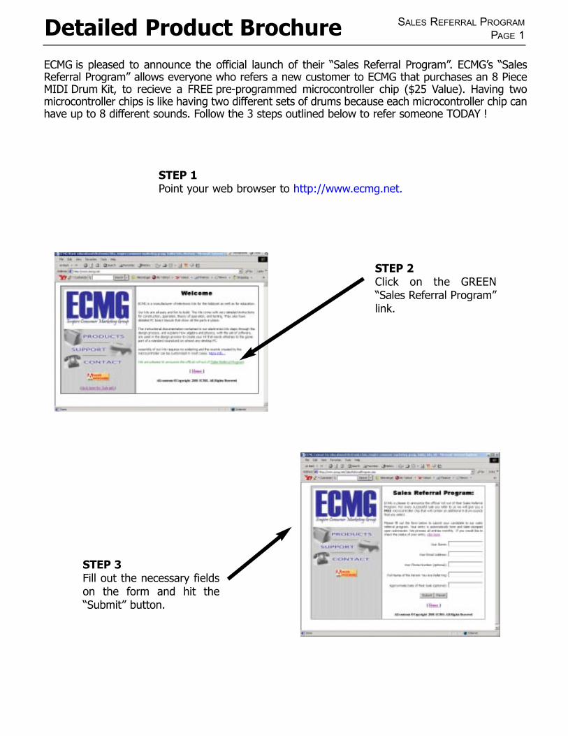
STEP 1Point your web browser to http://www.ecmg.net.
ECMG is pleased to announce the official launch of their “Sales Referral Program”. ECMG’s “SalesReferral Program” allows everyone who refers a new customer to ECMG that purchases an 8 PieceMIDI Drum Kit, to recieve a FREE pre-programmed microcontroller chip ($25 Value). Having twomicrocontroller chips is like having two different sets of drums because each microcontroller chip canhave up to 8 different sounds. Follow the 3 steps outlined below to refer someone TODAY !
STEP 2Click on the GREEN“Sales Referral Program”link.
STEP 3Fill out the necessary fieldson the form and hit the“Submit” button.