the data link layer - villanova computer sciencemdamian/past/networkssp09/n… · · 2009-02-053...
TRANSCRIPT
The Data Link Layer
Reading: Ch. 2.2, 2.6, 3.1, 3.2
2
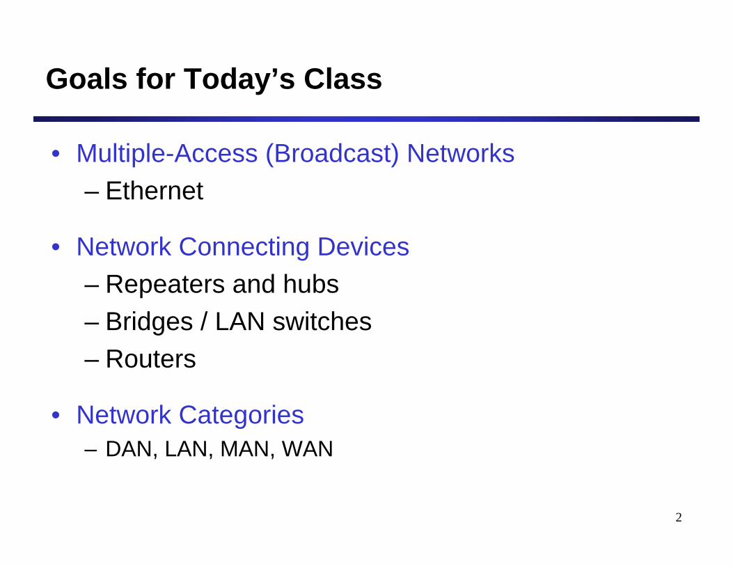
Goals for Today’s Class
• Multiple-Access (Broadcast) Networks– Ethernet
• Network Connecting Devices– Repeaters and hubs– Bridges / LAN switches– Routers
• Network Categories– DAN, LAN, MAN, WAN
3
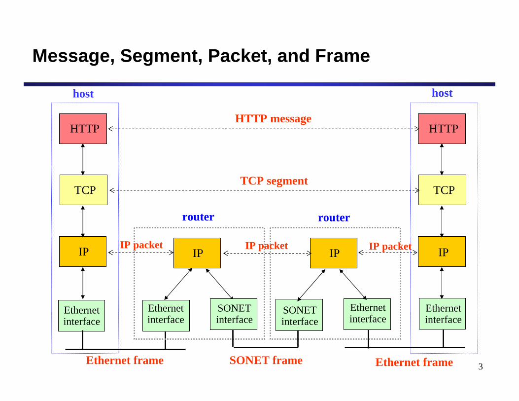
Message, Segment, Packet, and Frame
HTTP
TCP
IP
Ethernetinterface
HTTP
TCP
IP
Ethernetinterface
IP IP
Ethernetinterface
Ethernetinterface
SONETinterface
SONETinterface
host host
router router
HTTP message
TCP segment
IP packet IP packetIP packet
Ethernet frame Ethernet frameSONET frame
4
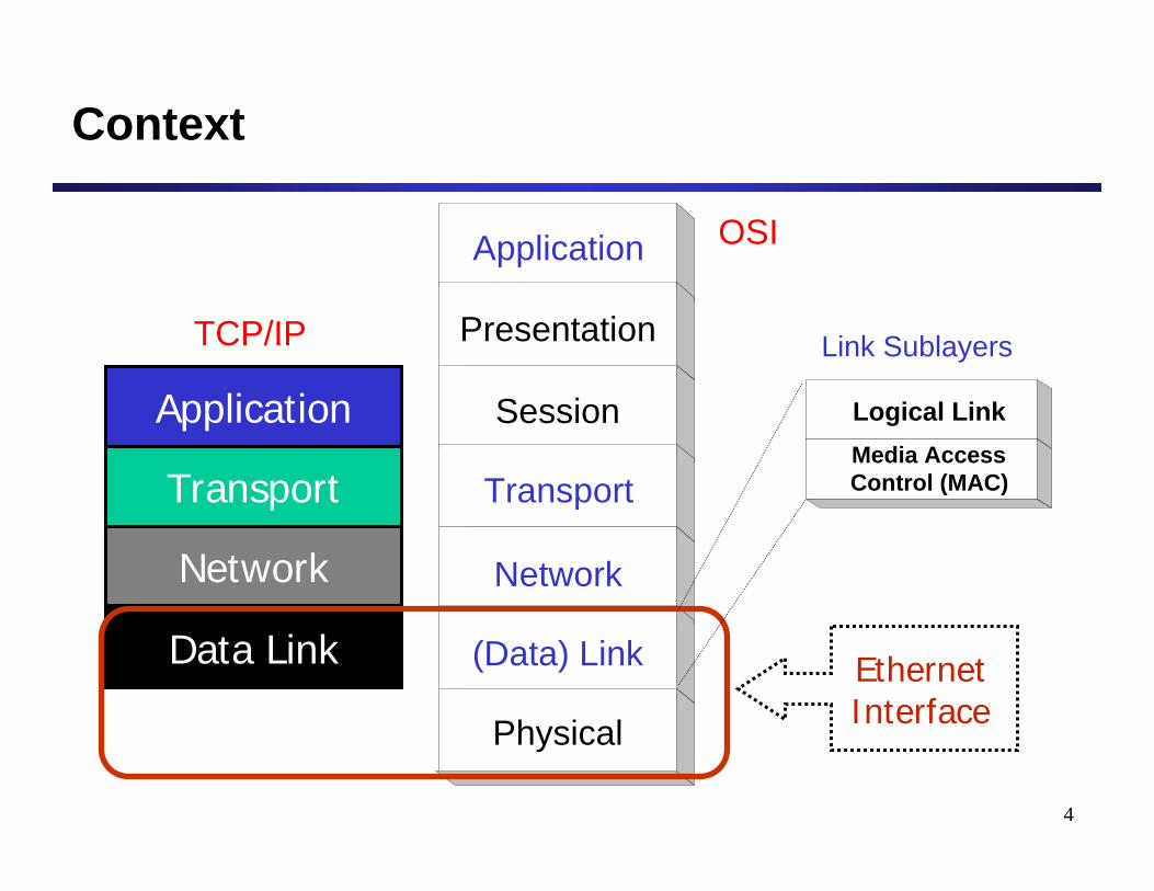
Context
Application
Transport
Network
Data Link EthernetInterface
Application
Presentation
Session
Transport
Network
(Data) Link
Physical
OSI
TCP/IP
Logical LinkMedia AccessControl (MAC)
Link Sublayers
5
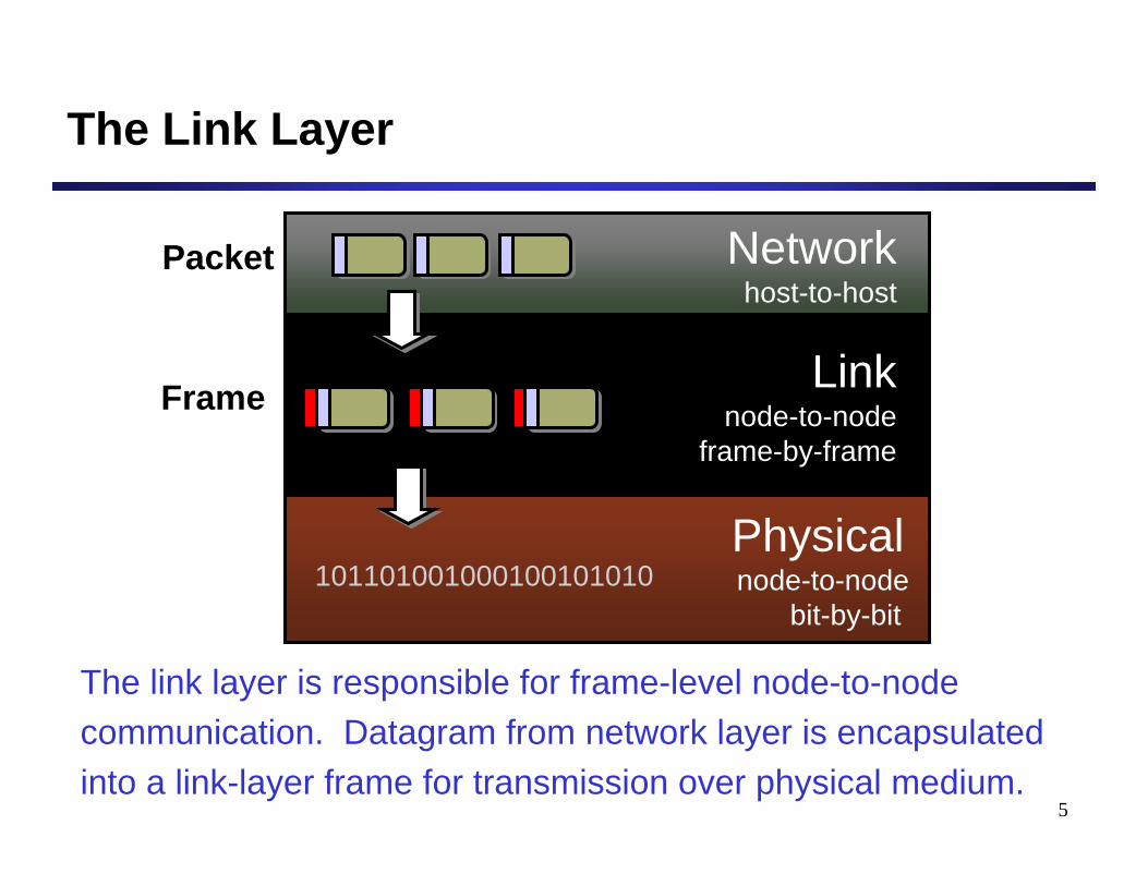
Physical node-to-node
bit-by-bit
Networkhost-to-host
Linknode-to-node
frame-by-frame
101101001000100101010
The Link Layer
Packet
Frame
The link layer is responsible for frame-level node-to-node communication. Datagram from network layer is encapsulated into a link-layer frame for transmission over physical medium.
6
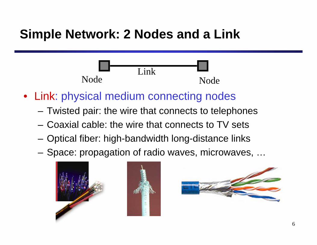
Simple Network: 2 Nodes and a Link
• Link: physical medium connecting nodes– Twisted pair: the wire that connects to telephones– Coaxial cable: the wire that connects to TV sets– Optical fiber: high-bandwidth long-distance links– Space: propagation of radio waves, microwaves, …
NodeLink
Node
7
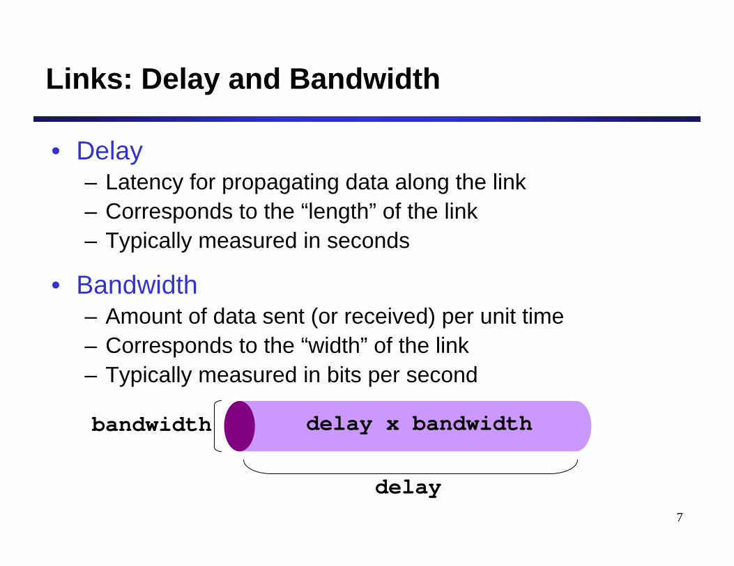
Links: Delay and Bandwidth
• Delay– Latency for propagating data along the link– Corresponds to the “length” of the link– Typically measured in seconds
• Bandwidth– Amount of data sent (or received) per unit time– Corresponds to the “width” of the link– Typically measured in bits per second
bandwidth
delay
delay x bandwidth
8
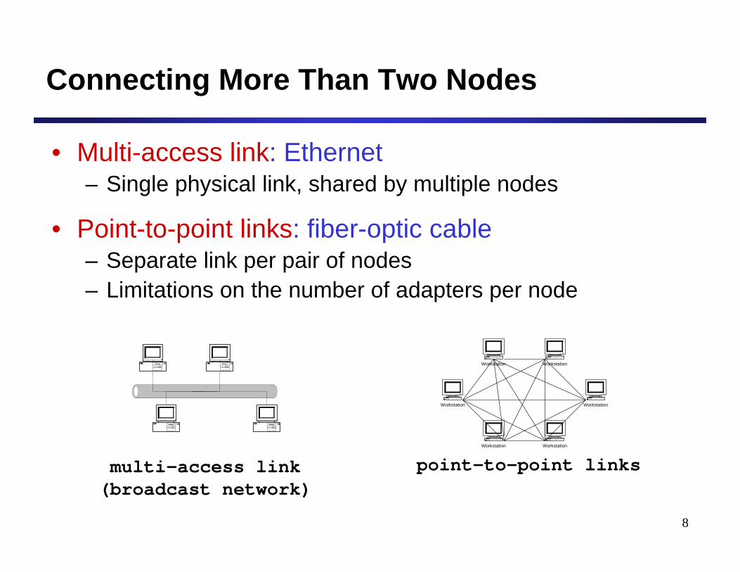
Connecting More Than Two Nodes
• Multi-access link: Ethernet– Single physical link, shared by multiple nodes
• Point-to-point links: fiber-optic cable– Separate link per pair of nodes– Limitations on the number of adapters per node
multi-access link(broadcast network)
point-to-point links
Workstation Workstation
Workstation
Workstation Workstation
Workstation
9
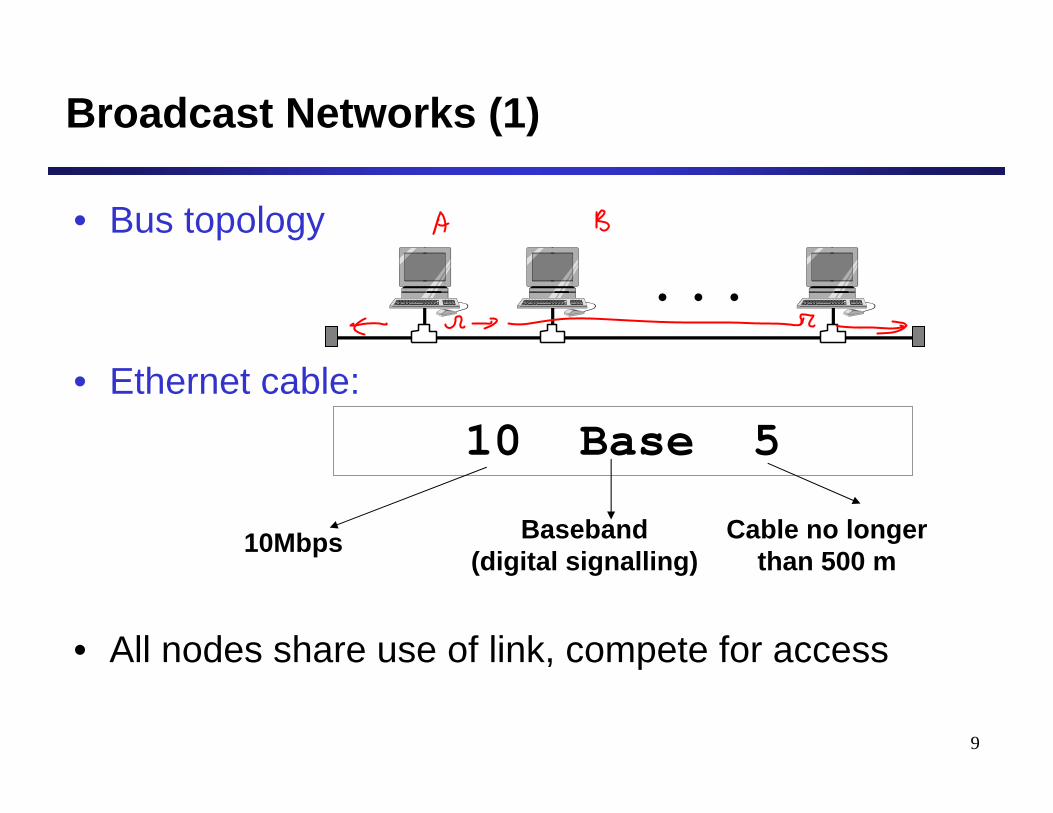
Broadcast Networks (1)
• Bus topology
• Ethernet cable:
• All nodes share use of link, compete for access
. . .
10 Base 5
10Mbps Baseband(digital signalling)
Cable no longerthan 500 m
10
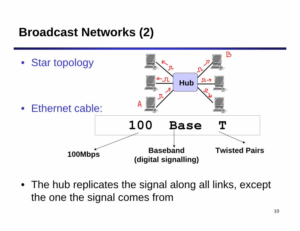
Broadcast Networks (2)
• Star topology
• Ethernet cable:
• The hub replicates the signal along all links, except the one the signal comes from
100 Base T
100Mbps Baseband(digital signalling)
Twisted Pairs
Hub
11
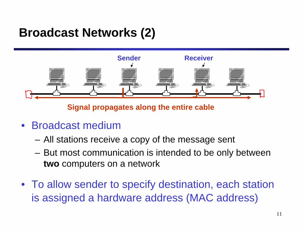
Broadcast Networks (2)
• Broadcast medium– All stations receive a copy of the message sent– But most communication is intended to be only between
two computers on a network
• To allow sender to specify destination, each station is assigned a hardware address (MAC address)
Sender Receiver
Signal propagates along the entire cable
12
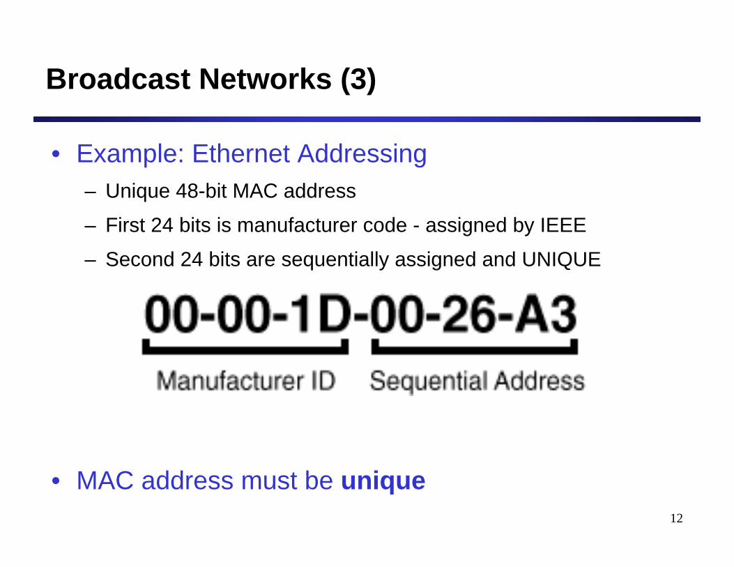
Broadcast Networks (3)
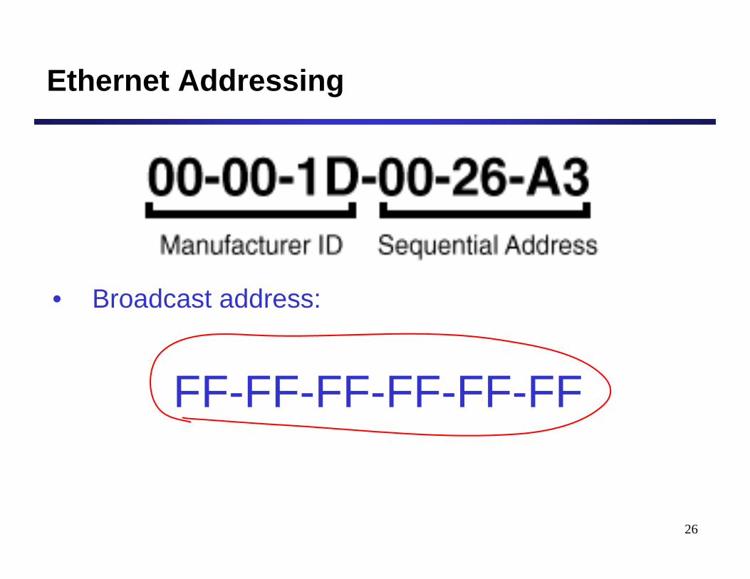
• Example: Ethernet Addressing– Unique 48-bit MAC address
– First 24 bits is manufacturer code - assigned by IEEE
– Second 24 bits are sequentially assigned and UNIQUE
• MAC address must be unique
13
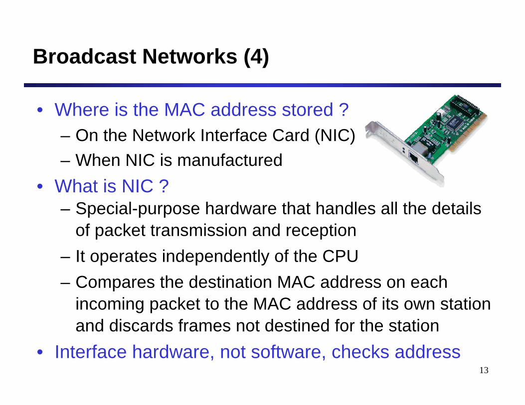
Broadcast Networks (4)
• Where is the MAC address stored ?– On the Network Interface Card (NIC)– When NIC is manufactured
• What is NIC ?– Special-purpose hardware that handles all the details
of packet transmission and reception– It operates independently of the CPU– Compares the destination MAC address on each
incoming packet to the MAC address of its own station and discards frames not destined for the station
• Interface hardware, not software, checks address
14
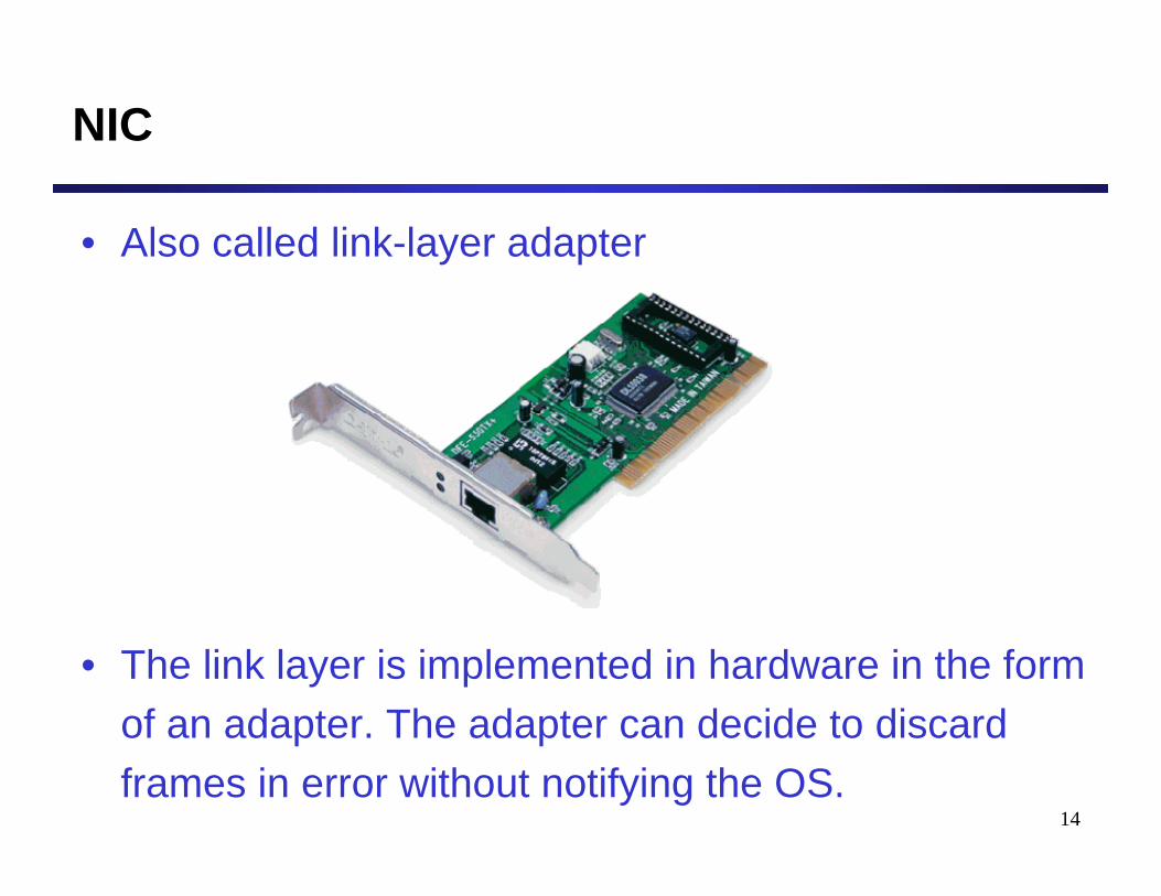
NIC
• Also called link-layer adapter
• The link layer is implemented in hardware in the form of an adapter. The adapter can decide to discard frames in error without notifying the OS.
Ethernet (802.3)
16
Ethernet
• Is the dominating LAN technology• IEEE 802.3 defines Ethernet• Layers specified by 802.3:
– Ethernet Physical Layer– Ethernet Medium Access (MAC) Sublayer
17
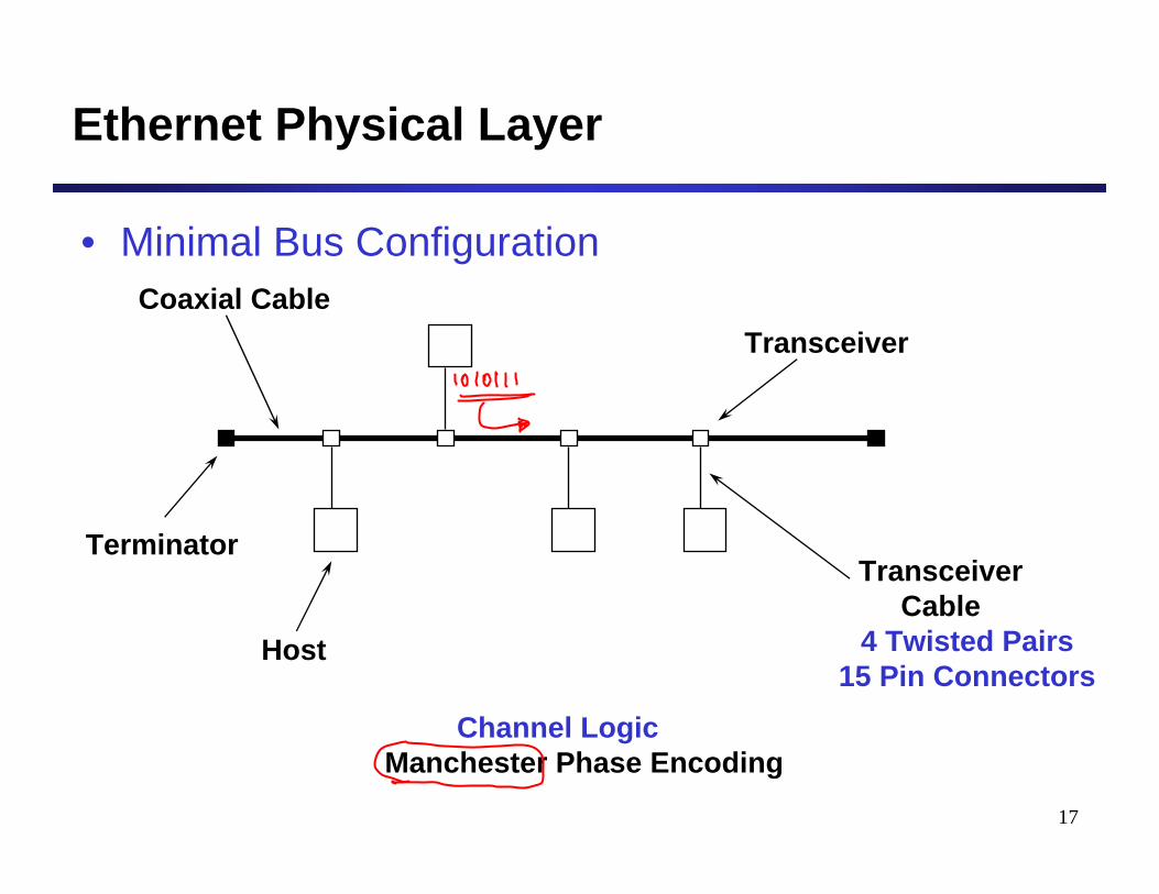
Ethernet Physical Layer
• Minimal Bus Configuration
Host
Transceiver
TransceiverCable
4 Twisted Pairs15 Pin Connectors
Coaxial Cable
Terminator
Channel LogicManchester Phase Encoding
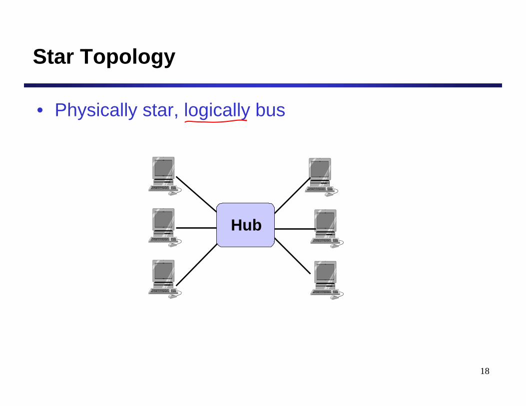
18
Star Topology
• Physically star, logically bus
Hub
19
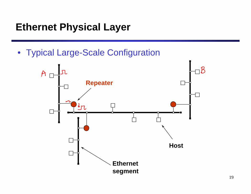
Ethernet Physical Layer
• Typical Large-Scale Configuration
Host
Repeater
Ethernetsegment
20
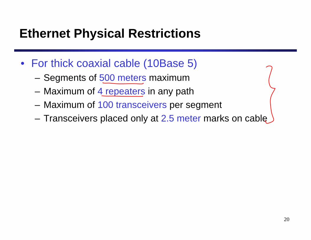
Ethernet Physical Restrictions
• For thick coaxial cable (10Base 5)– Segments of 500 meters maximum– Maximum of 4 repeaters in any path– Maximum of 100 transceivers per segment– Transceivers placed only at 2.5 meter marks on cable
21
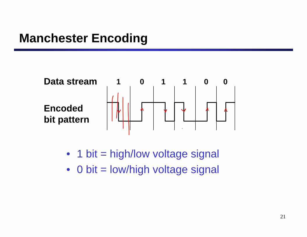
Manchester Encoding
• 1 bit = high/low voltage signal• 0 bit = low/high voltage signal
1 0 1 1 0 0Data stream
Encodedbit pattern

22
Ethernet: MAC Layer
• Data encapsulation– Frame Format– Addressing– Error Detection
• Access to the medium– CSMA/CD– Backoff Algorithm
23
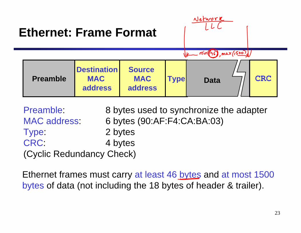
Ethernet: Frame Format
Preamble: 8 bytes used to synchronize the adapterMAC address: 6 bytes (90:AF:F4:CA:BA:03)Type: 2 bytesCRC: 4 bytes(Cyclic Redundancy Check)
PreambleSource
MACaddress
DestinationMAC
addressType CRC
Ethernet frames must carry at least 46 bytes and at most 1500 bytes of data (not including the 18 bytes of header & trailer).
Data
24
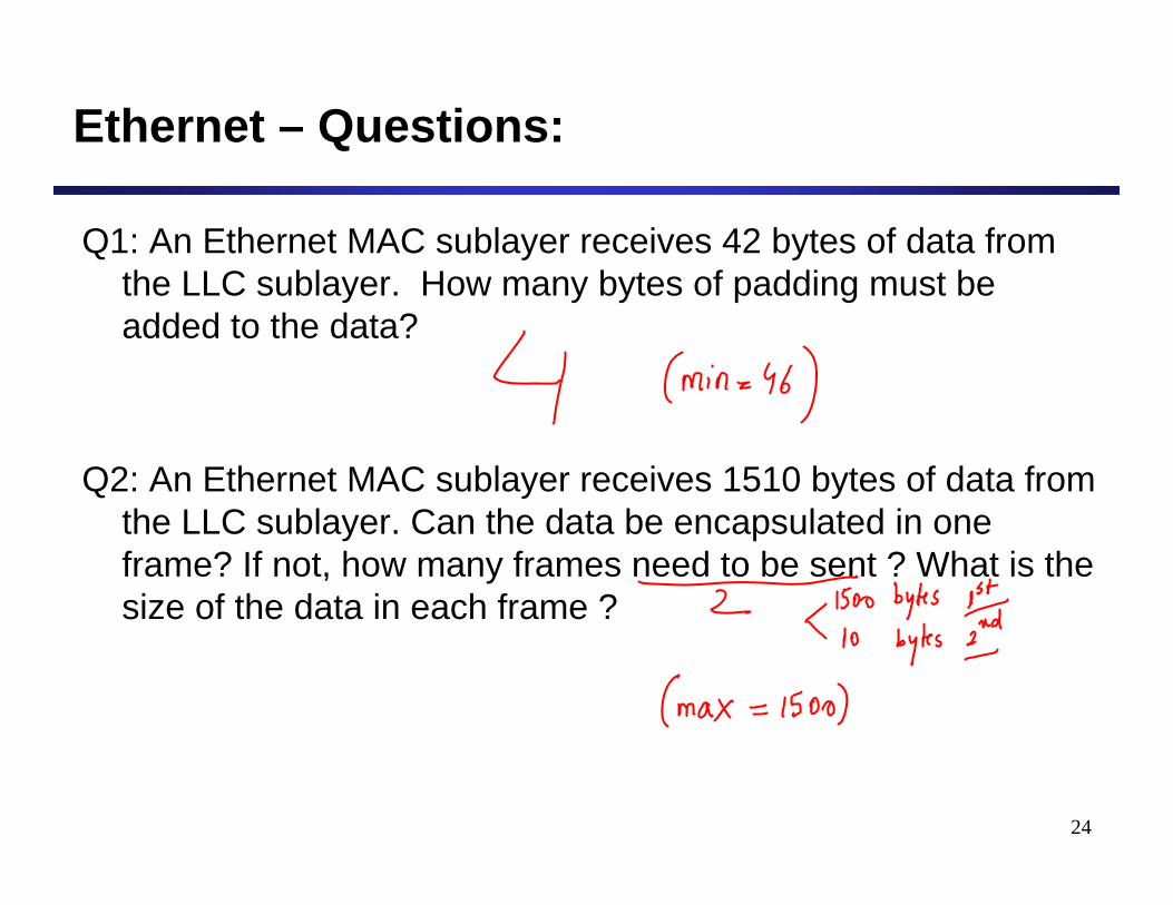
Ethernet – Questions:
Q1: An Ethernet MAC sublayer receives 42 bytes of data from the LLC sublayer. How many bytes of padding must be added to the data?
Q2: An Ethernet MAC sublayer receives 1510 bytes of data from the LLC sublayer. Can the data be encapsulated in one frame? If not, how many frames need to be sent ? What is the size of the data in each frame ?

25
Ethernet: MAC Layer
• Data encapsulation– Frame Format– Addressing– Error Detection
• Access to the medium– CSMA/CD– Backoff Algorithm
26
Ethernet Addressing
• Broadcast address:
FF-FF-FF-FF-FF-FF
27
Question
• MAC addresses only have significance within the context of a local-area network. So, why are MAC addresses globally unique?
28
Ethernet: MAC Layer
• Data encapsulation– Frame Format– Addressing– Error Detection
• Access to the medium– CSMA/CD– Backoff Algorithm
29
Ethernet: Medium Access
• When more than one nodes share a medium, we need a protocol to coordinate access to the medium.
• Ethernet uses CSMA/CD.
CS Carrier Sense
MA Multiple Access
CD Collision Detection
30
Medium Access Protocols
• CSMA– 1-Persistent CSMA– Non-Persistent CSMA– p-Persistent CSMA
• CSMA/CD
• Idea: – Listen to the channel before transmitting a packet.
31
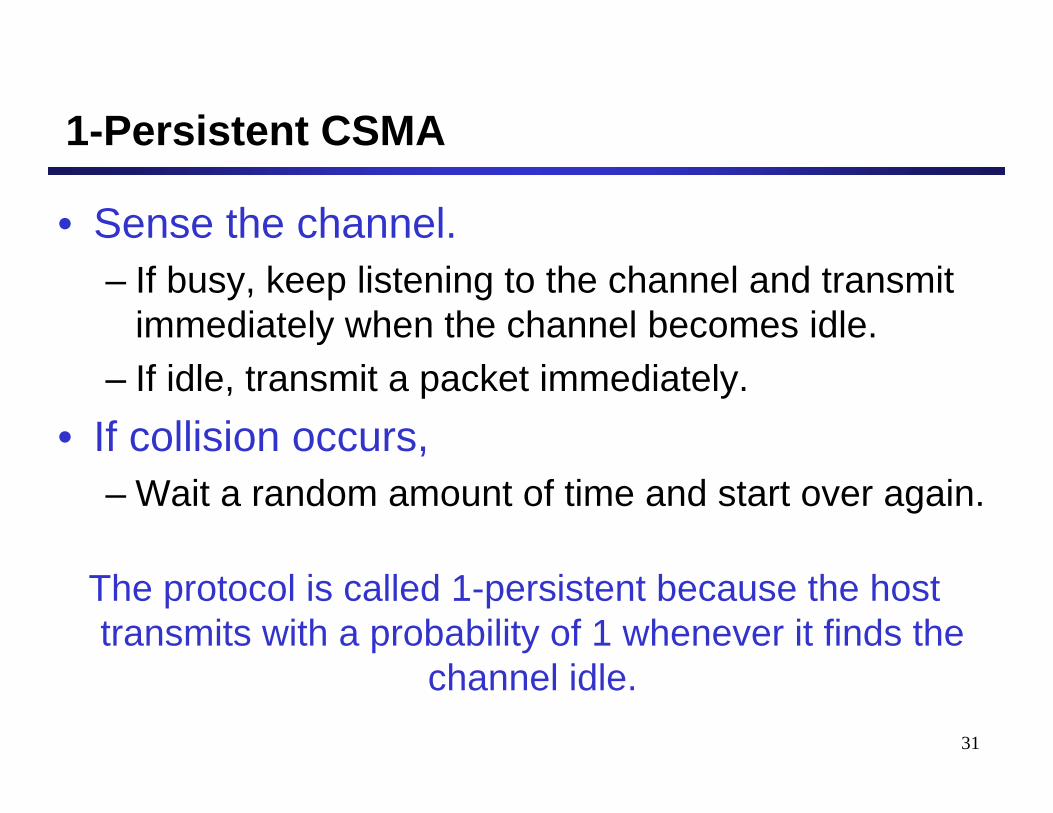
1-Persistent CSMA
• Sense the channel.– If busy, keep listening to the channel and transmit
immediately when the channel becomes idle.– If idle, transmit a packet immediately.
• If collision occurs,– Wait a random amount of time and start over again.
The protocol is called 1-persistent because the host transmits with a probability of 1 whenever it finds the
channel idle.
32
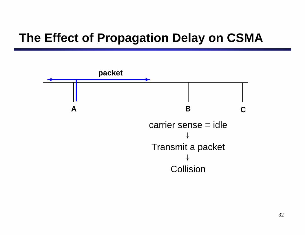
The Effect of Propagation Delay on CSMA
carrier sense = idle
Transmit a packet
Collision
A B
packet
C
33
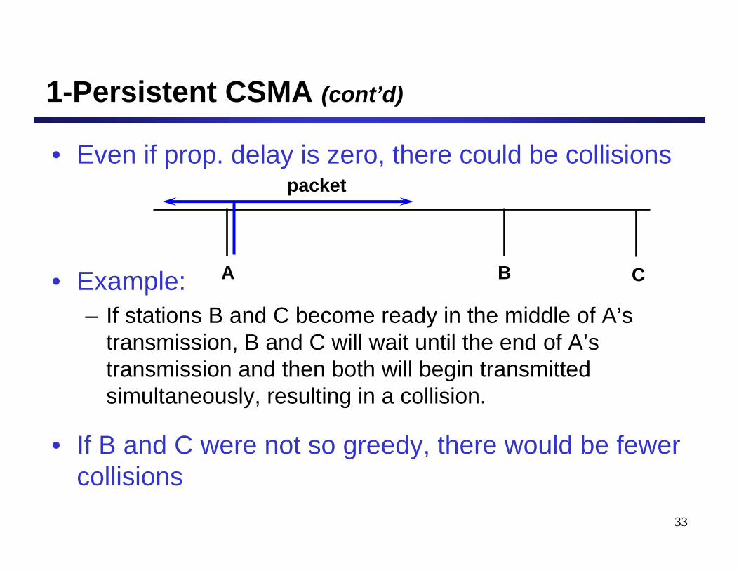
1-Persistent CSMA (cont’d)
• Even if prop. delay is zero, there could be collisions
• Example:– If stations B and C become ready in the middle of A’s
transmission, B and C will wait until the end of A’s transmission and then both will begin transmitted simultaneously, resulting in a collision.
• If B and C were not so greedy, there would be fewer collisions
A B
packet
C
34
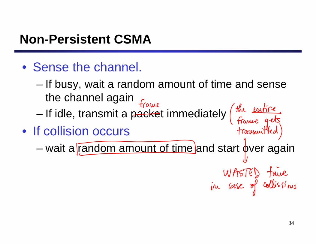
Non-Persistent CSMA
• Sense the channel.– If busy, wait a random amount of time and sense
the channel again– If idle, transmit a packet immediately
• If collision occurs– wait a random amount of time and start over again
35
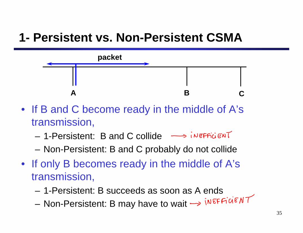
1- Persistent vs. Non-Persistent CSMA
• If B and C become ready in the middle of A’s transmission,– 1-Persistent: B and C collide– Non-Persistent: B and C probably do not collide
• If only B becomes ready in the middle of A’s transmission,– 1-Persistent: B succeeds as soon as A ends– Non-Persistent: B may have to wait
A B
packet
C
36
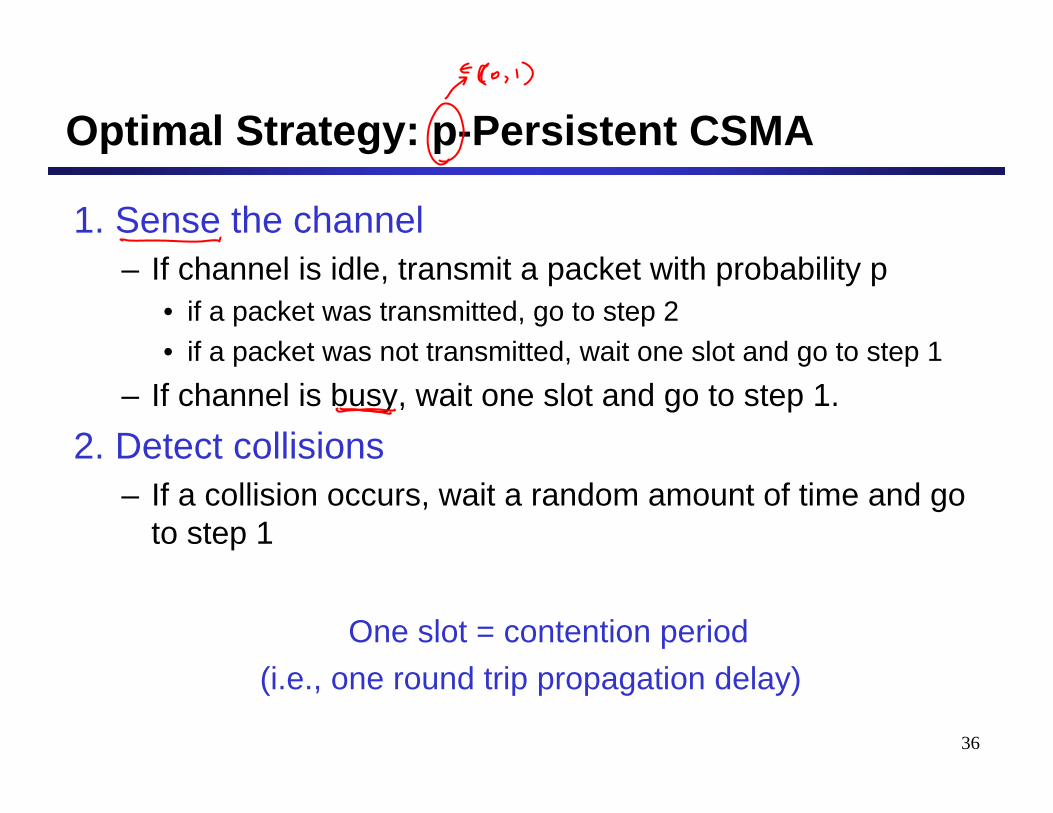
Optimal Strategy: p-Persistent CSMA
1. Sense the channel– If channel is idle, transmit a packet with probability p
• if a packet was transmitted, go to step 2• if a packet was not transmitted, wait one slot and go to step 1
– If channel is busy, wait one slot and go to step 1.2. Detect collisions
– If a collision occurs, wait a random amount of time and go to step 1
One slot = contention period (i.e., one round trip propagation delay)
37
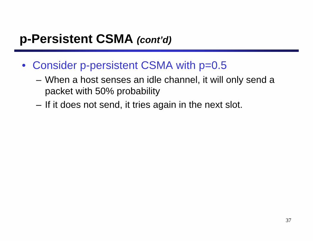
p-Persistent CSMA (cont’d)
• Consider p-persistent CSMA with p=0.5– When a host senses an idle channel, it will only send a
packet with 50% probability– If it does not send, it tries again in the next slot.
38
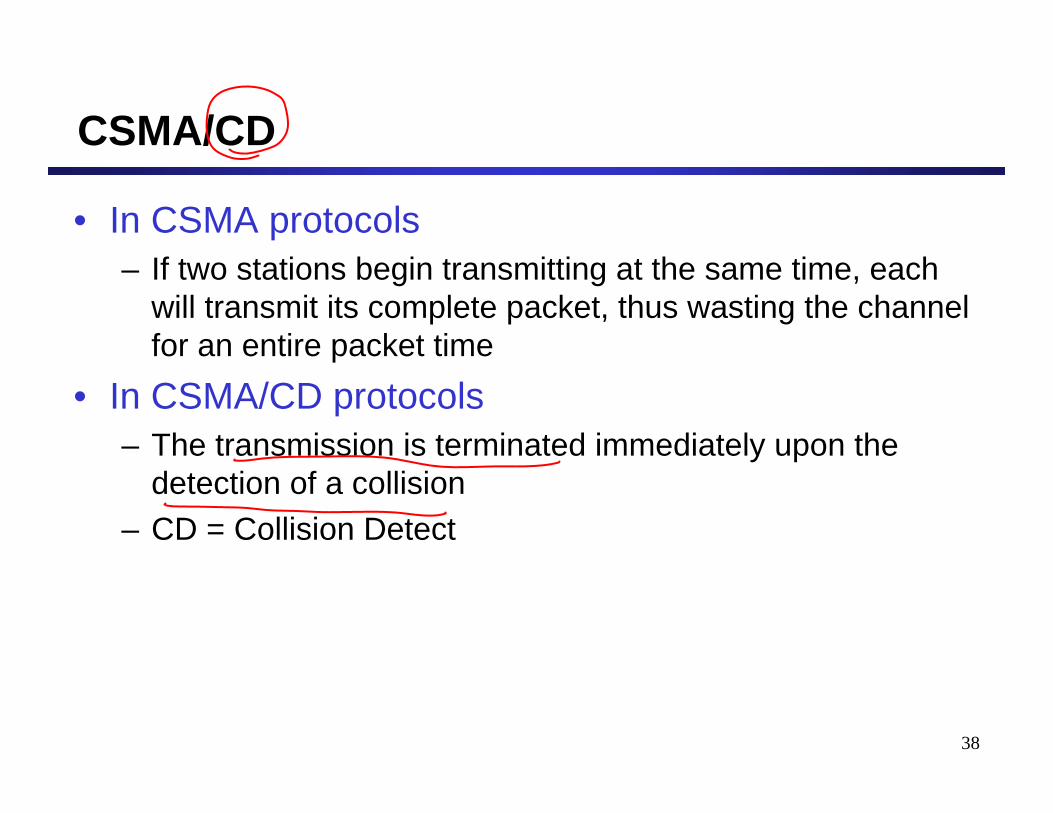
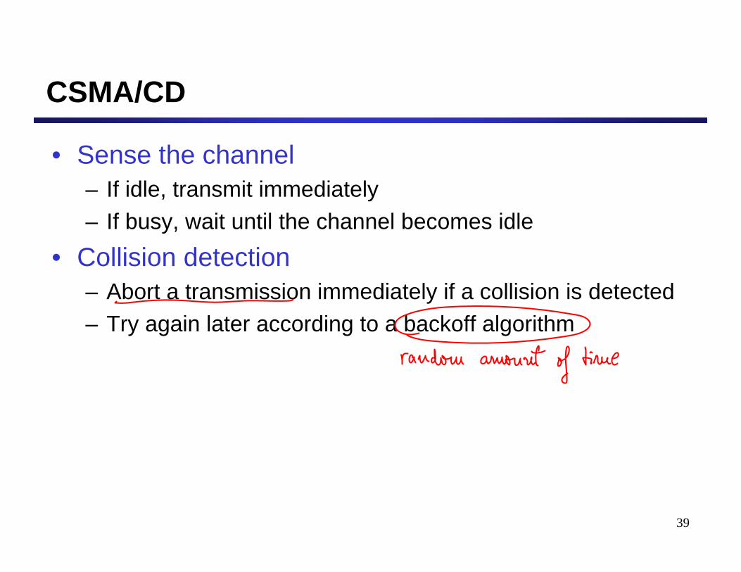
CSMA/CD
• In CSMA protocols– If two stations begin transmitting at the same time, each
will transmit its complete packet, thus wasting the channel for an entire packet time
• In CSMA/CD protocols– The transmission is terminated immediately upon the
detection of a collision– CD = Collision Detect
39
CSMA/CD
• Sense the channel– If idle, transmit immediately– If busy, wait until the channel becomes idle
• Collision detection– Abort a transmission immediately if a collision is detected– Try again later according to a backoff algorithm
40
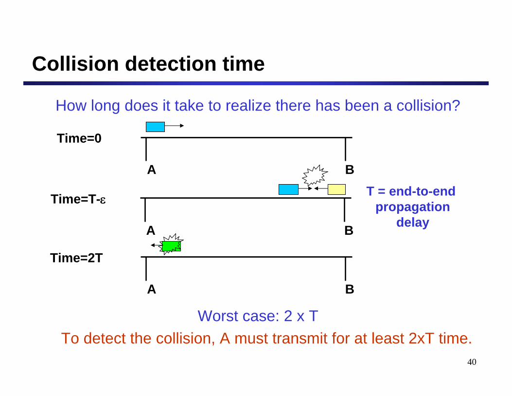
Collision detection time
How long does it take to realize there has been a collision?
Worst case: 2 x T To detect the collision, A must transmit for at least 2xT time.
A B
Time=0
A B
Time=T-ε
A B
Time=2T
T = end-to-end propagation
delay

41
Ethernet: MAC Layer
• Data encapsulation– Frame Format– Addressing– Error Detection
• Access to the medium– CSMA/CD– Backoff Algorithm
42
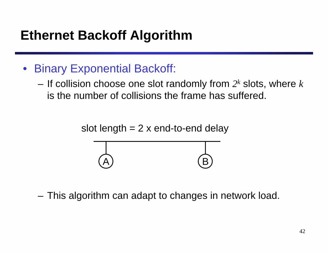
Ethernet Backoff Algorithm
• Binary Exponential Backoff:– If collision choose one slot randomly from 2k slots, where k
is the number of collisions the frame has suffered.
– This algorithm can adapt to changes in network load.
slot length = 2 x end-to-end delay
A B
43
Binary Exponential Backoff
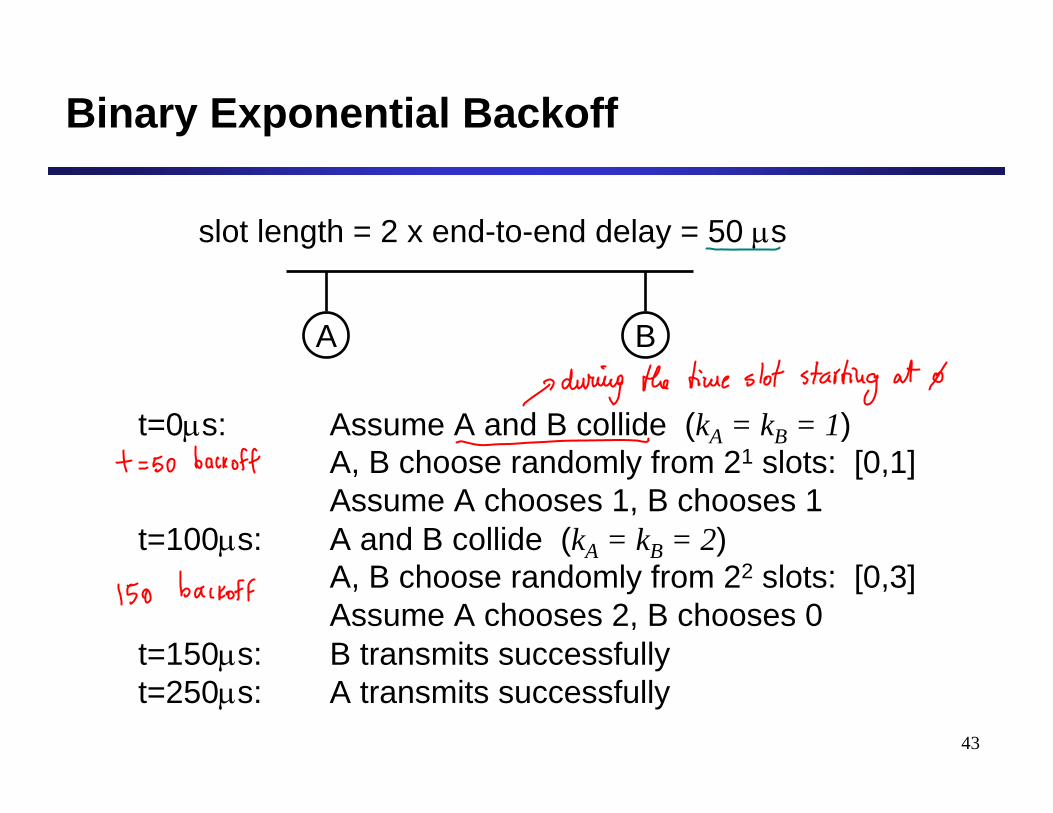
slot length = 2 x end-to-end delay = 50 μs
A B
t=0μs: Assume A and B collide (kA = kB = 1)A, B choose randomly from 21 slots: [0,1]Assume A chooses 1, B chooses 1
t=100μs: A and B collide (kA = kB = 2)A, B choose randomly from 22 slots: [0,3]Assume A chooses 2, B chooses 0
t=150μs: B transmits successfullyt=250μs: A transmits successfully
44
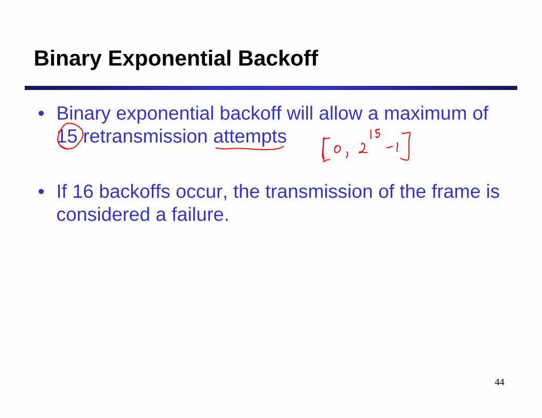
Binary Exponential Backoff
• Binary exponential backoff will allow a maximum of 15 retransmission attempts
• If 16 backoffs occur, the transmission of the frame is considered a failure.
45
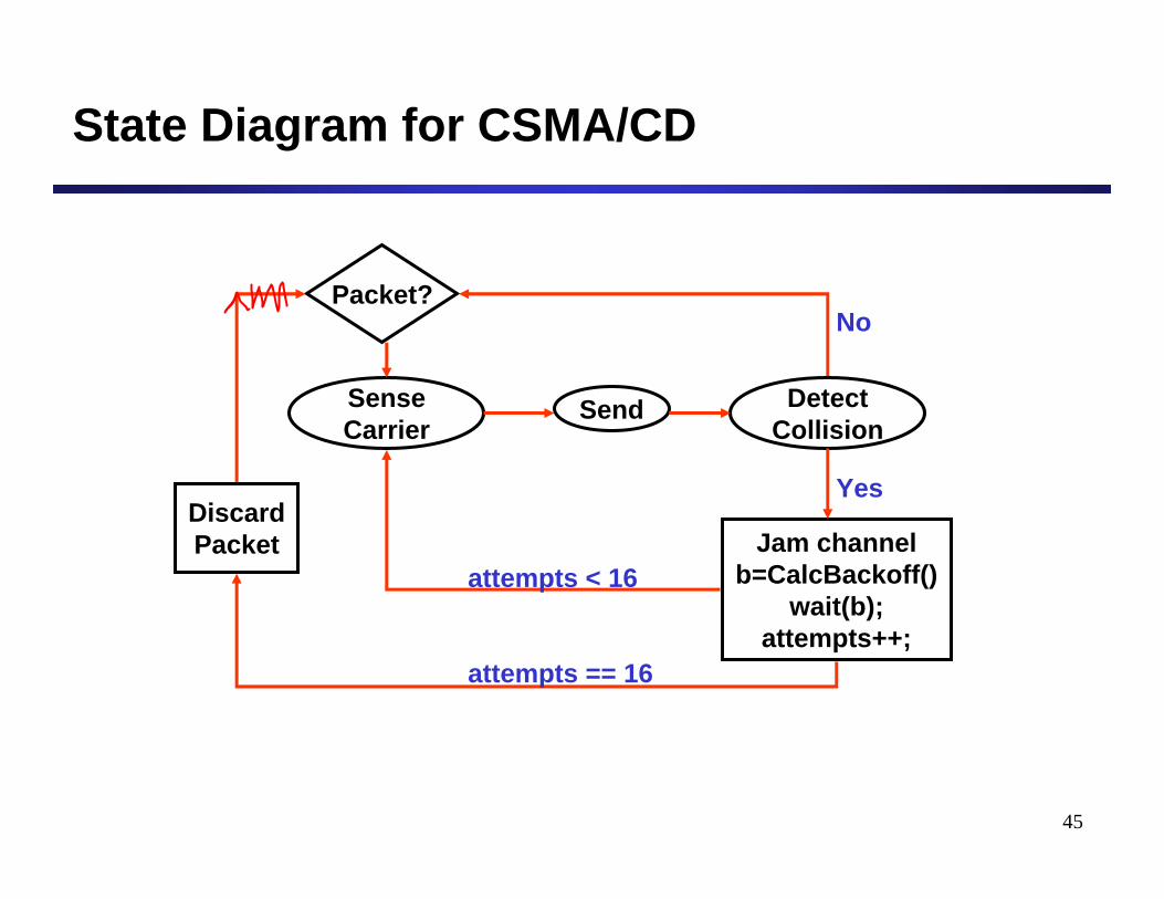
State Diagram for CSMA/CD
Packet?
Sense Carrier
Discard Packet
Send Detect Collision
Jam channel b=CalcBackoff()
wait(b);attempts++;
No
Yes
attempts < 16
attempts == 16
46
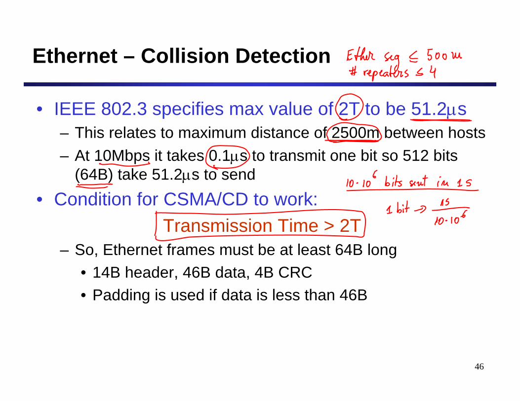
Ethernet – Collision Detection
• IEEE 802.3 specifies max value of 2T to be 51.2μs– This relates to maximum distance of 2500m between hosts– At 10Mbps it takes 0.1μs to transmit one bit so 512 bits
(64B) take 51.2μs to send• Condition for CSMA/CD to work:
Transmission Time > 2T– So, Ethernet frames must be at least 64B long
• 14B header, 46B data, 4B CRC• Padding is used if data is less than 46B
47
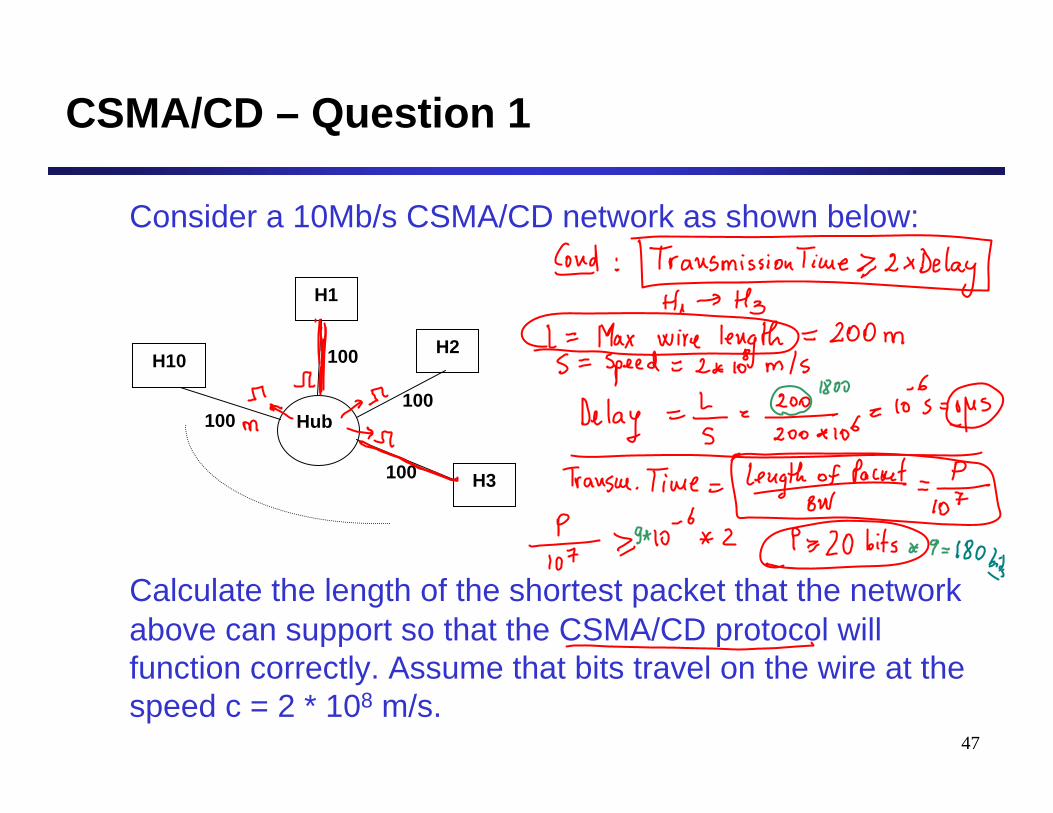
CSMA/CD – Question 1
Consider a 10Mb/s CSMA/CD network as shown below:
Calculate the length of the shortest packet that the network above can support so that the CSMA/CD protocol will function correctly. Assume that bits travel on the wire at the speed c = 2 * 108 m/s.
H1
H2
H3
H10
Hub
100
100
100
100
48
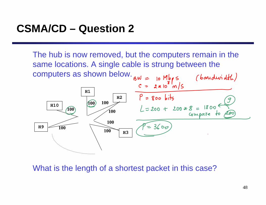
CSMA/CD – Question 2
The hub is now removed, but the computers remain in the same locations. A single cable is strung between the computers as shown below.
What is the length of a shortest packet in this case?
H1H2
H10
H9
100 100
100
100
100 H3100
100
49
CSMA/CD – Question 3
• Why do Ethernet adaptors select a random back-off time before trying to transmit a frame following a collision? Why do they pick the random back-off time from a larger range after each collision?
Extending Networks with
Interconnecting Devices

51
Goals for Today’s Class
• Multiple-Access (Broadcast) Networks– Ethernet
• Network Connecting Devices– Repeaters and hubs– Bridges / LAN switches– Routers
• Network Categories– DAN, LAN, MAN, WAN
52
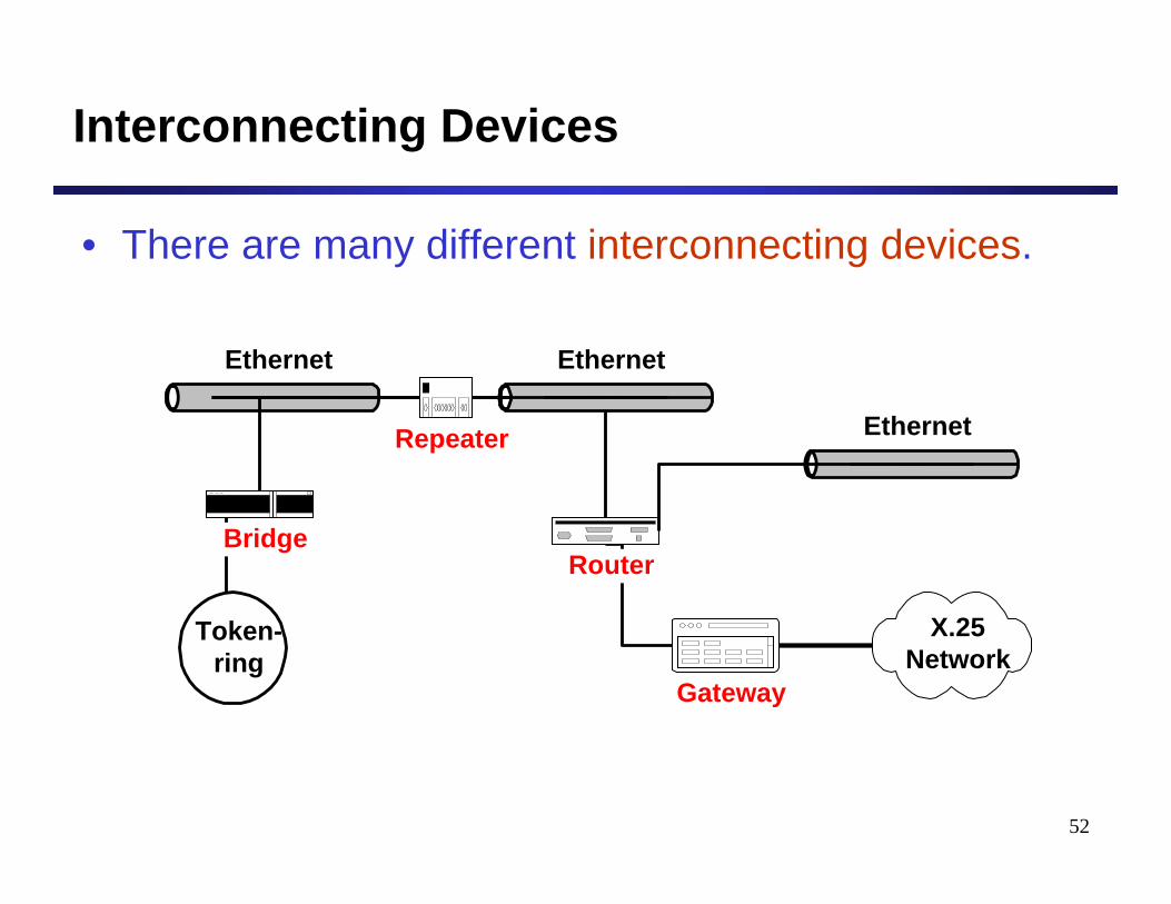
Interconnecting Devices
• There are many different interconnecting devices.
Ethernet
Router
Ethernet
Ethernet
Token-ring
Gateway
Bridge
Repeater
X.25Network
53
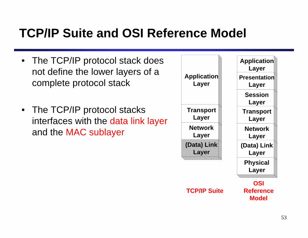
TCP/IP Suite and OSI Reference Model
• The TCP/IP protocol stack does not define the lower layers of a complete protocol stack
• The TCP/IP protocol stacks interfaces with the data link layerand the MAC sublayer
ApplicationLayer
ApplicationLayer
PresentationLayer
SessionLayer
TransportLayer
NetworkLayer
(Data) LinkLayer
PhysicalLayer
TransportLayer
NetworkLayer
OSIReference
Model
(Data) LinkLayer
TCP/IP Suite
54
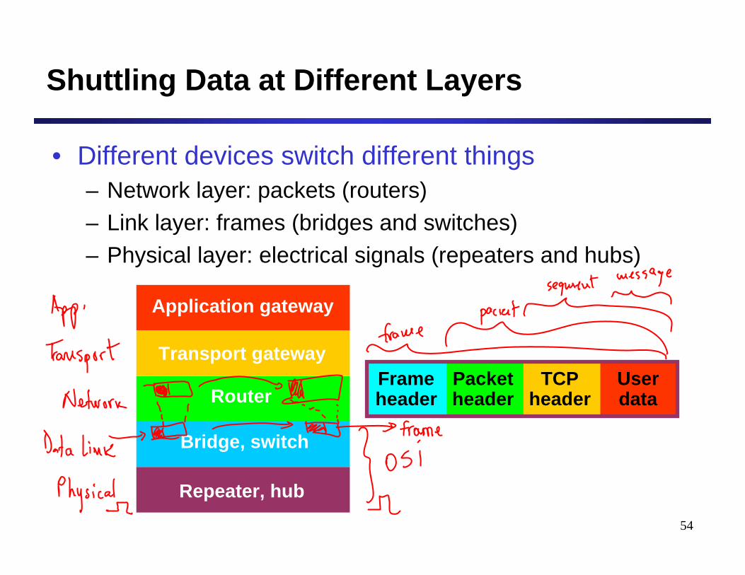
Shuttling Data at Different Layers
• Different devices switch different things– Network layer: packets (routers)– Link layer: frames (bridges and switches)– Physical layer: electrical signals (repeaters and hubs)
Application gateway
Transport gateway
Router
Bridge, switch
Repeater, hub
Frameheader
Packetheader
TCPheader
Userdata
55
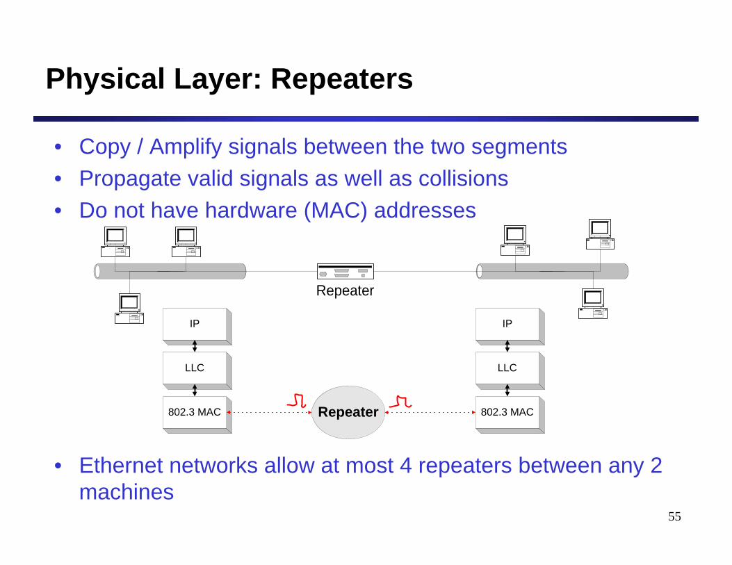
Physical Layer: Repeaters
• Copy / Amplify signals between the two segments• Propagate valid signals as well as collisions• Do not have hardware (MAC) addresses
• Ethernet networks allow at most 4 repeaters between any 2 machines
Repeater
IP
LLC
802.3 MAC
IP
LLC
802.3 MACRepeater
56
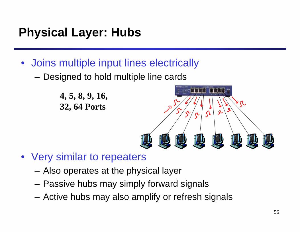
Physical Layer: Hubs
• Joins multiple input lines electrically– Designed to hold multiple line cards
• Very similar to repeaters– Also operates at the physical layer– Passive hubs may simply forward signals– Active hubs may also amplify or refresh signals
4, 5, 8, 9, 16, 32, 64 Ports
57
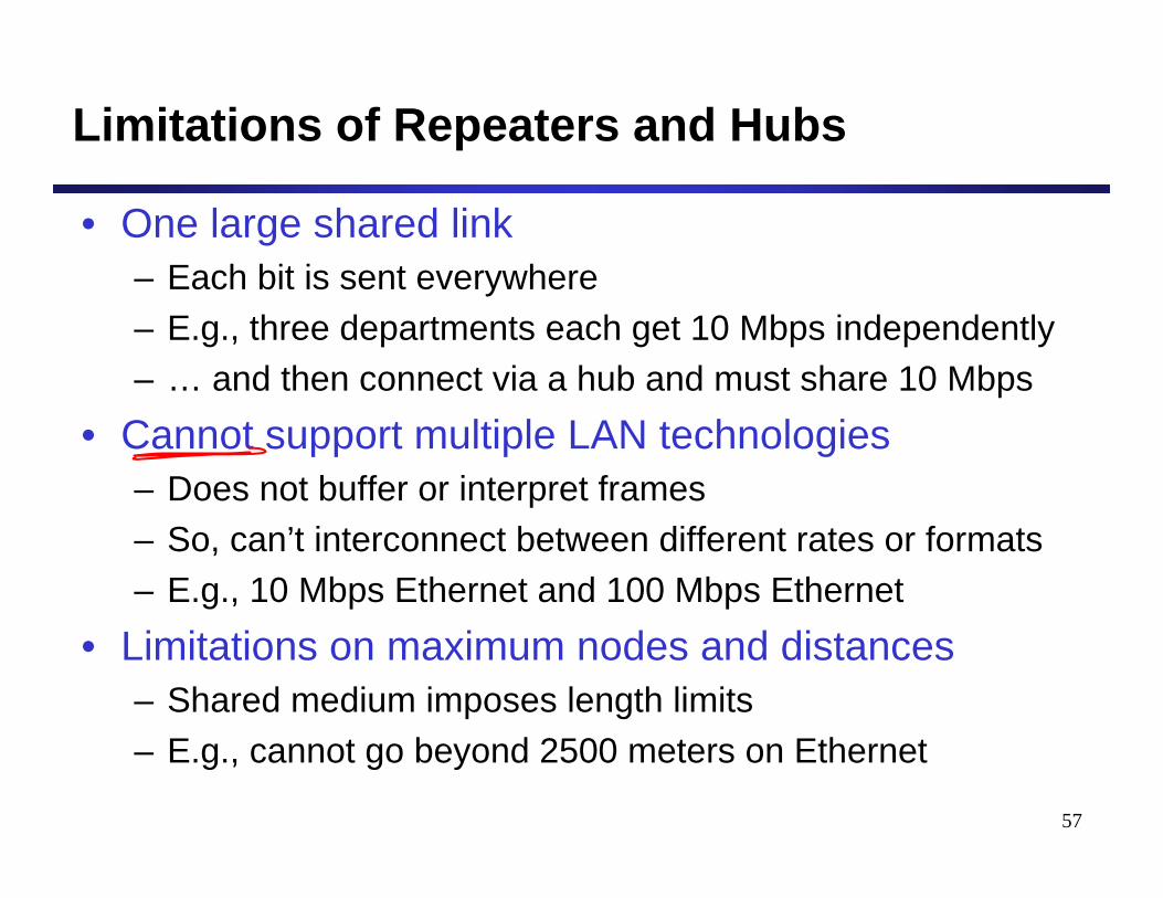
Limitations of Repeaters and Hubs
• One large shared link– Each bit is sent everywhere– E.g., three departments each get 10 Mbps independently– … and then connect via a hub and must share 10 Mbps
• Cannot support multiple LAN technologies– Does not buffer or interpret frames– So, can’t interconnect between different rates or formats– E.g., 10 Mbps Ethernet and 100 Mbps Ethernet
• Limitations on maximum nodes and distances– Shared medium imposes length limits – E.g., cannot go beyond 2500 meters on Ethernet

58
Goals for Today’s Class
• Multiple-Access (Broadcast) Networks– Ethernet
• Network Connecting Devices– Repeaters and hubs– Bridges / LAN switches– Routers
• Network Categories– DAN, LAN, MAN, WAN
59
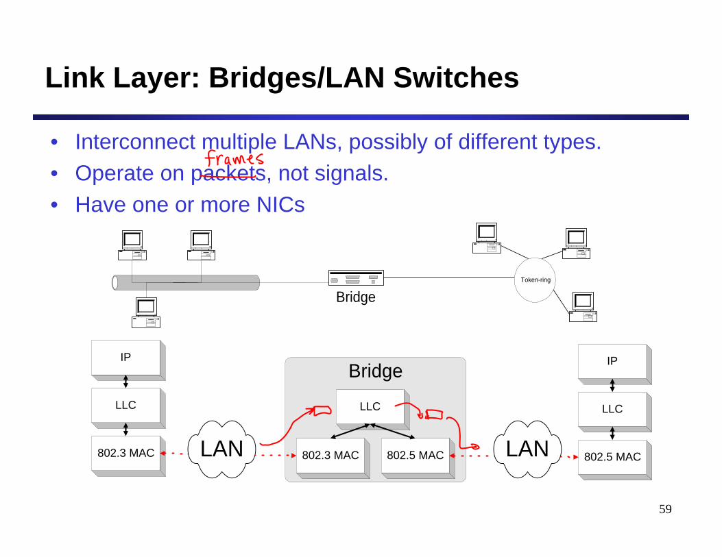
Link Layer: Bridges/LAN Switches
• Interconnect multiple LANs, possibly of different types.• Operate on packets, not signals.• Have one or more NICs
BridgeToken-ring
BridgeIP
LLC
802.3 MAC 802.3 MAC 802.5 MAC
LLC
IP
LLC
802.5 MACLAN LAN
60
Bridges vs. LAN Switches
• A network switch is a computer networking device that connects network segments. The term commonly refers to a network bridge that processes and routes data at the Data link layer (layer 2) of the OSI model. One way to think of a layer 2 switch is as a multiport bridge.
• Switches that additionally process data at the Network layer (layer 3 and above) are often referred to as Layer 3 switches.
[Wikipedia]http://en.wikipedia.org/wiki/Network_switch
61
Bridges vs. LAN Switches
• Layer 2 switching is highly efficient because there is no modification to the data packet, only to the frame encapsulation of the packet, and only when the data packet is passing through dissimilar media (such as from Ethernet to FDDI).
[Wikipedia]http://en.wikipedia.org/wiki/LAN_switching
62
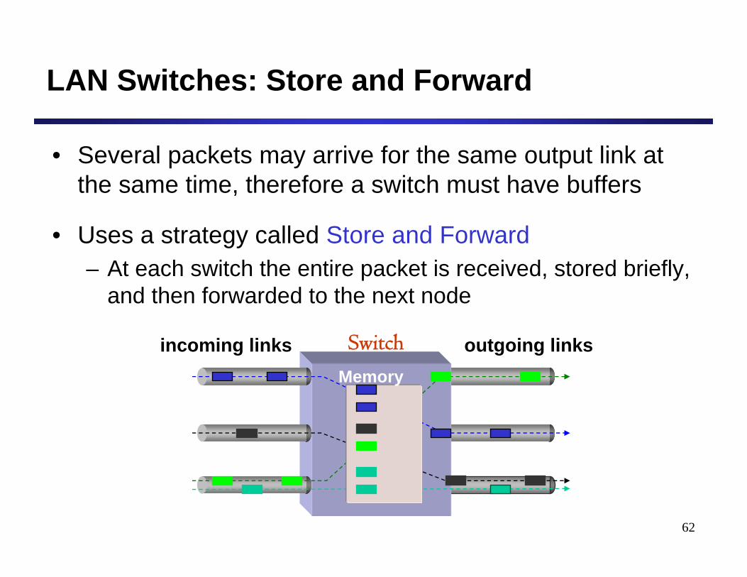
LAN Switches: Store and Forward
• Several packets may arrive for the same output link at the same time, therefore a switch must have buffers
• Uses a strategy called Store and Forward– At each switch the entire packet is received, stored briefly,
and then forwarded to the next node
incoming links outgoing linksSwitchMemory
63
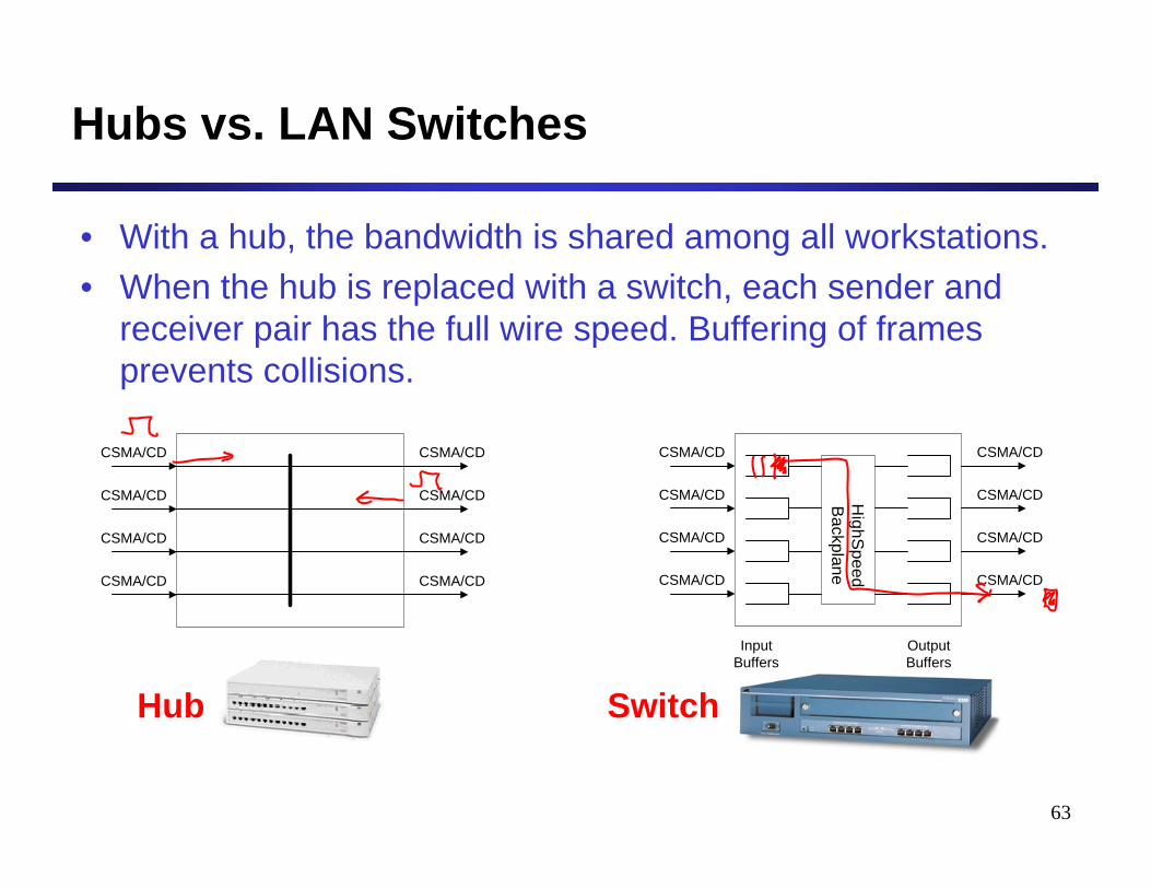
Hubs vs. LAN Switches
• With a hub, the bandwidth is shared among all workstations. • When the hub is replaced with a switch, each sender and
receiver pair has the full wire speed. Buffering of frames prevents collisions.
HighS
peedB
ackplane
CSMA/CD
CSMA/CD
CSMA/CD
CSMA/CD
CSMA/CD
CSMA/CD
CSMA/CD
CSMA/CD
OutputBuffers
InputBuffers
CSMA/CD
CSMA/CD
CSMA/CD
CSMA/CD
CSMA/CD
CSMA/CD
CSMA/CD
CSMA/CD
Hub Switch
64
Link Layer: LAN Switches
• Network switches are increasingly replacing shared media hubs in order to increase bandwidth. For example, a 16-port 100BaseT hub shares the total 100 Mbps bandwidth with all 16 attached nodes. By replacing the hub with a switch, each sender/receiver pair has the full 100 Mbps capacity. Each port on the switch can give full bandwidth to a single server or client station or it can be connected to a hub with several stations.
[TechWeb Encyclopedia]
65
Hubs and Switches Used Together
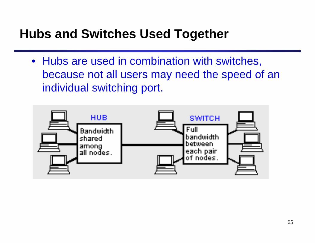
• Hubs are used in combination with switches, because not all users may need the speed of an individual switching port.
66
Bridge/LAN Switch Filtering
• Bridges learn from experience and build and maintain address tables of the nodes on the network.– Extract destination address from the frame
– Look up the destination in a table
– Forward the frame to the appropriate LAN segment
• More about this later …
67
Advantages Over Hubs/Repeaters
• Only forwards frames as needed– Filters frames to avoid unnecessary load on segments– Sends frames only to segments that need to see them
• Extends the geographic span of the network– Separate segments allow longer distances
• Improves privacy by limiting scope of frames– Hosts can “snoop” the traffic traversing their segment– … but not all the rest of the traffic
• Can join segments using different technologies
68
Disadvantages Over Hubs/Repeaters
• Delay in forwarding frames– Bridge/switch must receive and parse the frame– … and perform a look-up to decide where to forward– Storing and forwarding the packet introduces delay– Solution: cut-through switching
• Need to learn where to forward frames– Bridge/switch needs to construct a forwarding table– Ideally, without intervention from network administrators– Solution: self-learning
• Higher cost– More complicated devices that cost more money
69
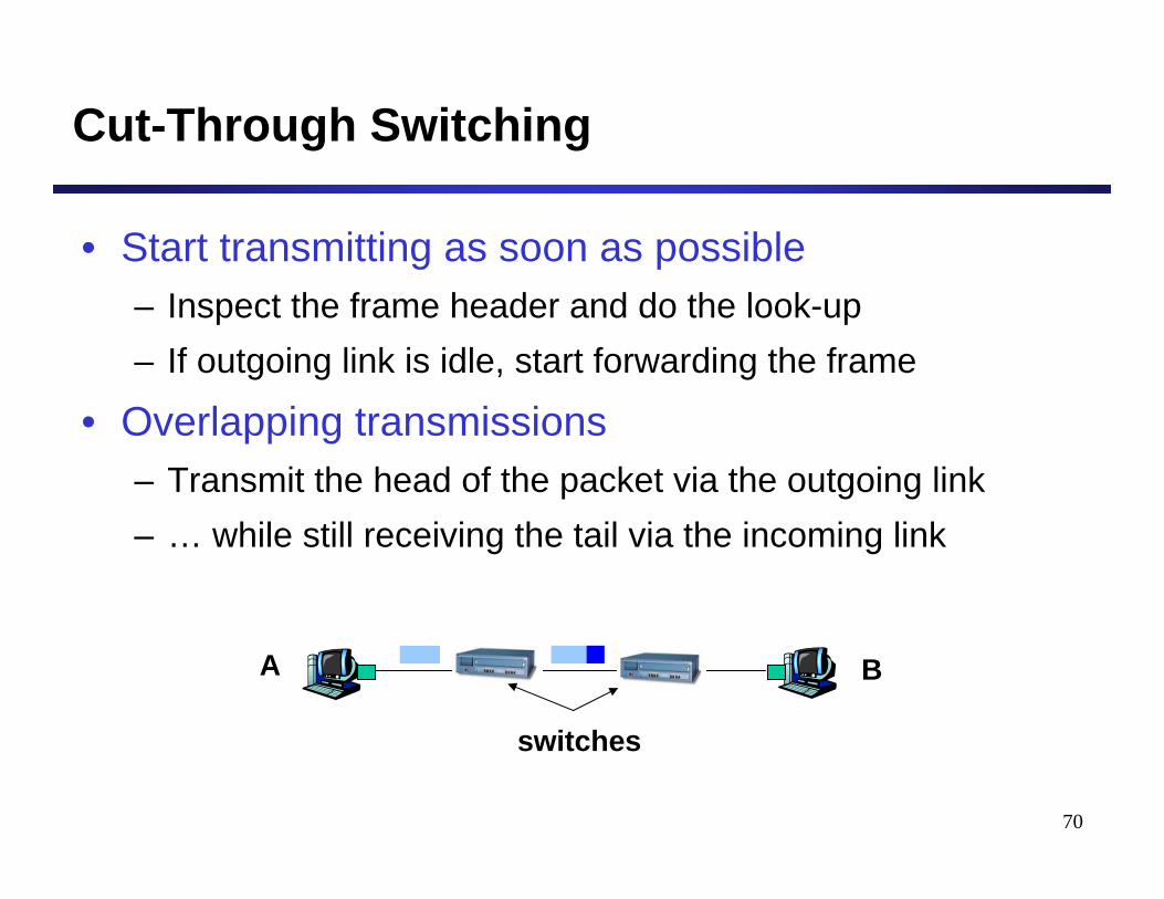
Motivation For Cut-Through Switching
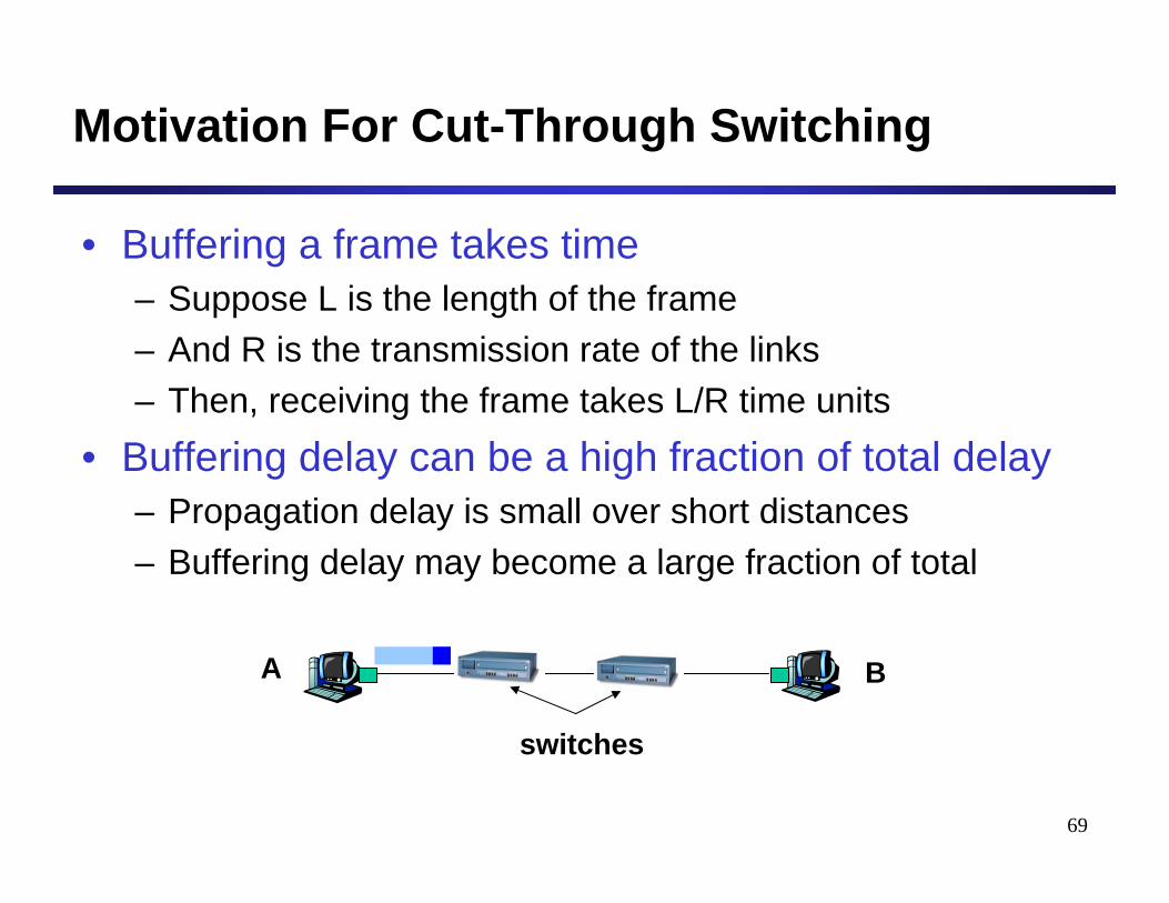
• Buffering a frame takes time– Suppose L is the length of the frame– And R is the transmission rate of the links– Then, receiving the frame takes L/R time units
• Buffering delay can be a high fraction of total delay– Propagation delay is small over short distances– Buffering delay may become a large fraction of total
A B
switches
70
Cut-Through Switching
• Start transmitting as soon as possible– Inspect the frame header and do the look-up– If outgoing link is idle, start forwarding the frame
• Overlapping transmissions– Transmit the head of the packet via the outgoing link– … while still receiving the tail via the incoming link
A B
switches

71
Goals for Today’s Class
• Multiple-Access (Broadcast) Networks– Ethernet
• Network Connecting Devices– Repeaters and hubs– Bridges / LAN switches– Routers
• Network Categories– DAN, LAN, MAN, WAN
72
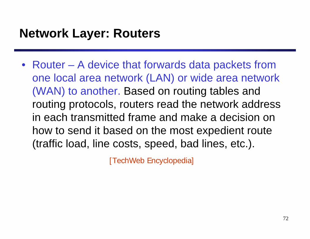
Network Layer: Routers
• Router – A device that forwards data packets from one local area network (LAN) or wide area network (WAN) to another. Based on routing tables and routing protocols, routers read the network address in each transmitted frame and make a decision on how to send it based on the most expedient route (traffic load, line costs, speed, bad lines, etc.).
[TechWeb Encyclopedia]
73
Network Layer: Routers
Subnet-work
Router
Subnet-work
Router
Subnet-work
Application
TCP
IP
NetworkAccess
Application
TCP
IP
NetworkAccess
IP protocol IP protocol
DataLink
NetworkAccess
IP
NetworkAccess
NetworkAccess
IP
NetworkAccess
DataLink
DataLink
IP protocol
RouterRouter HostHost
74
Bridges vs. Routers (1)
• Bridges work at the data link layer, whereas routers work at the network layer.
• Bridges are protocol independent; routers are protocol dependent.
• Bridges are faster than routers because they do not have to read the protocol to get routing information.
75
Bridges vs. Routers (2)
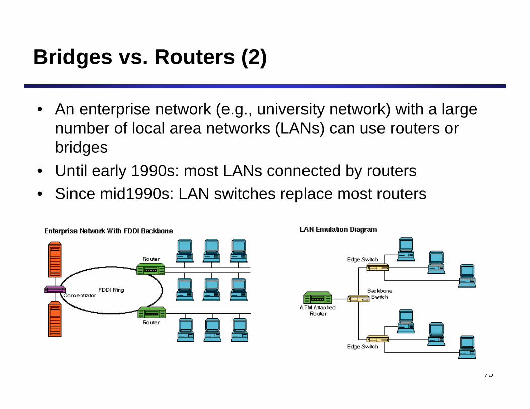
• An enterprise network (e.g., university network) with a large number of local area networks (LANs) can use routers or bridges
• Until early 1990s: most LANs connected by routers• Since mid1990s: LAN switches replace most routers
76
Internet
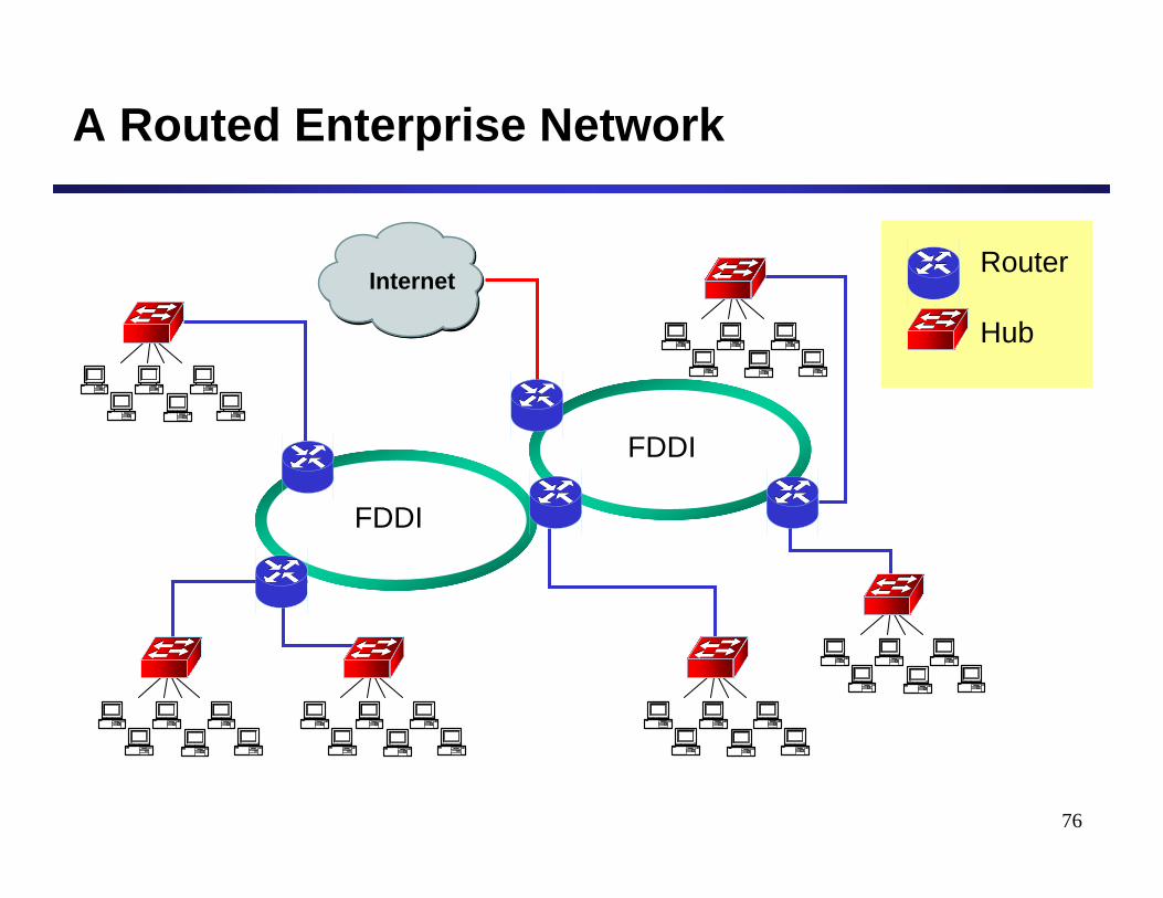
A Routed Enterprise Network
Router
Hub
FDDI
FDDI
77
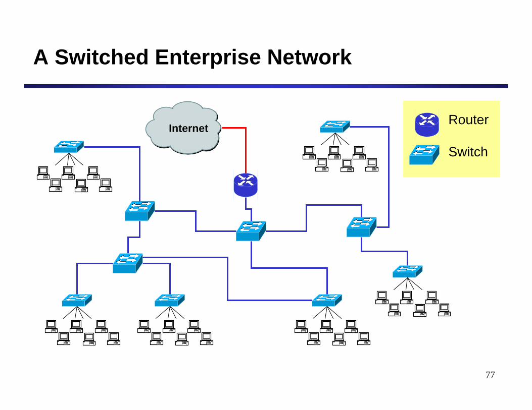
Internet
A Switched Enterprise Network
Router
Switch
78
Bridges vs. Routers (3)
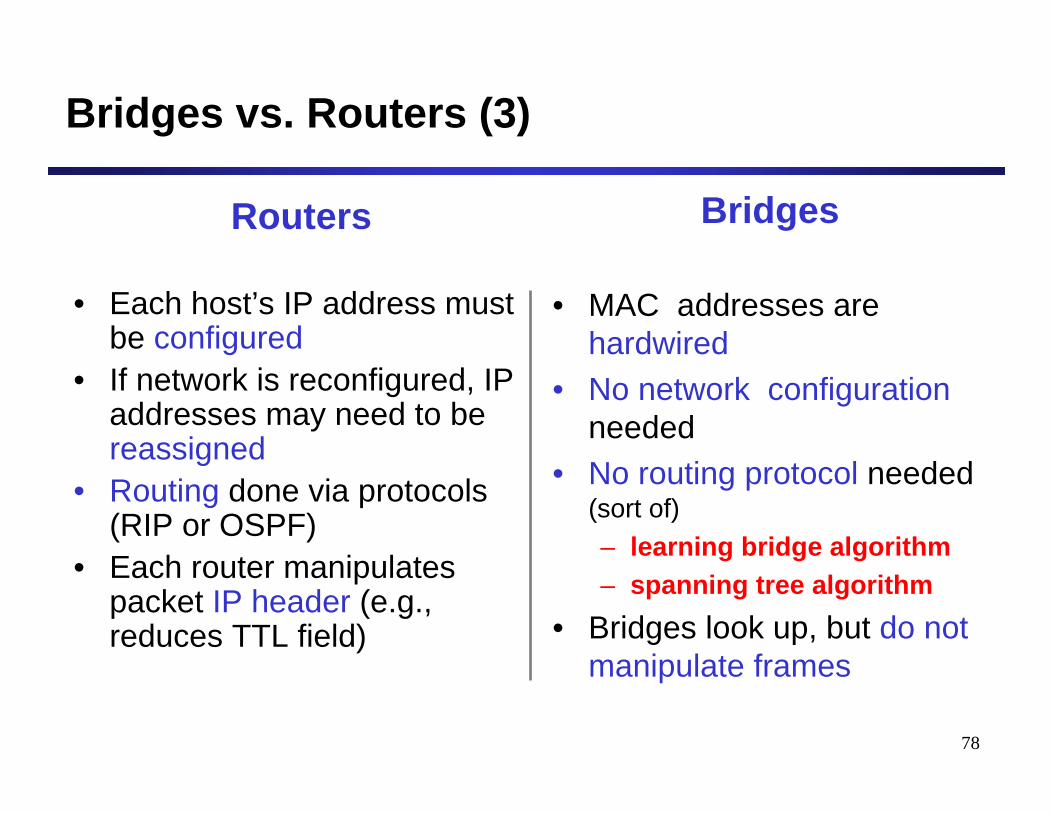
Routers
• Each host’s IP address must be configured
• If network is reconfigured, IP addresses may need to bereassigned
• Routing done via protocols (RIP or OSPF)
• Each router manipulates packet IP header (e.g., reduces TTL field)
Bridges
• MAC addresses arehardwired
• No network configuration needed
• No routing protocol needed (sort of)– learning bridge algorithm– spanning tree algorithm
• Bridges look up, but do not manipulate frames
79
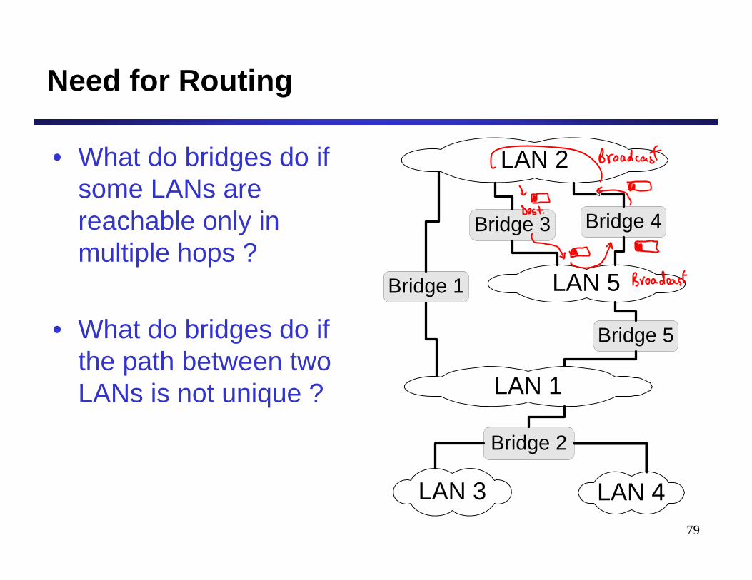
Need for Routing
• What do bridges do if some LANs are reachable only in multiple hops ?
• What do bridges do if the path between two LANs is not unique ?
LAN 2
Bridge 2
LAN 5
LAN 3
LAN 1
LAN 4
Bridge 5
Bridge 4Bridge 3
d
Bridge 1
80
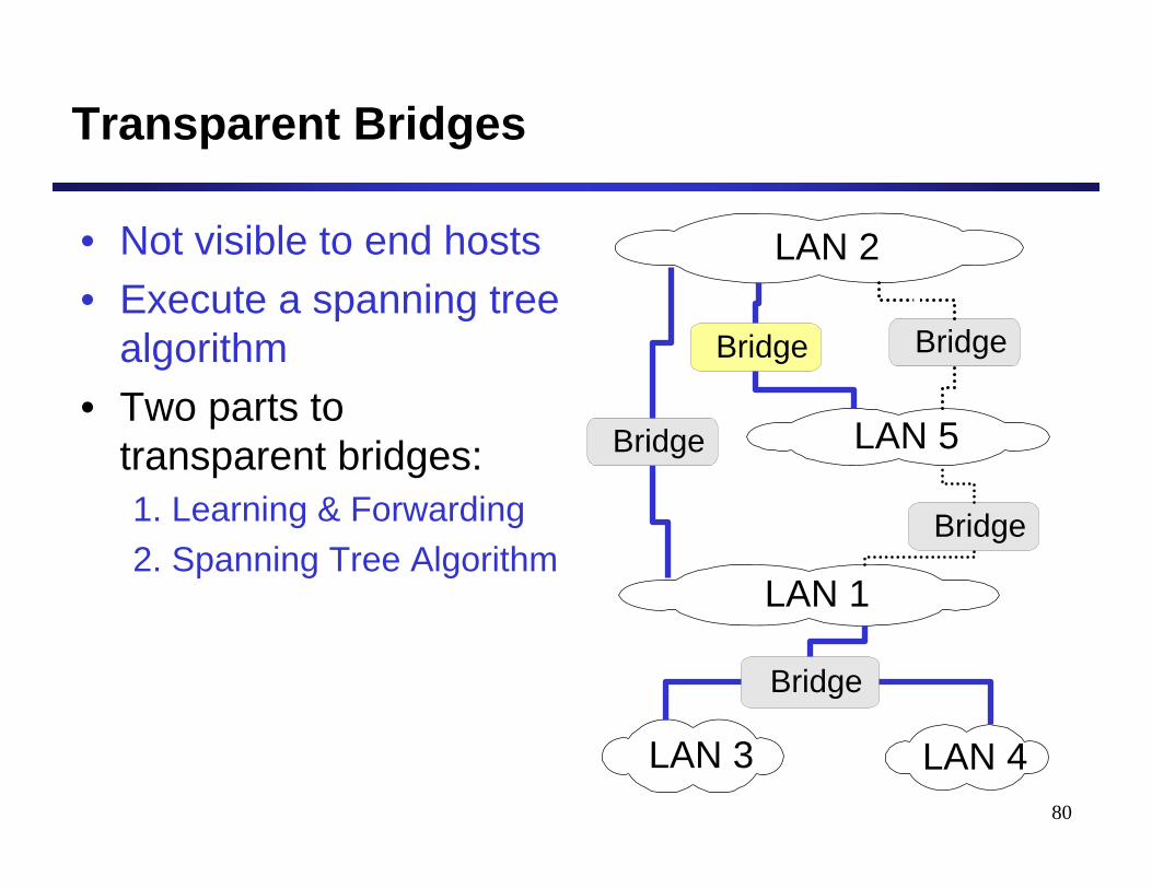
Transparent Bridges
• Not visible to end hosts• Execute a spanning tree
algorithm• Two parts to
transparent bridges:1. Learning & Forwarding2. Spanning Tree Algorithm
LAN 2
Bridge
LAN 5
LAN 3
LAN 1
LAN 4
Bridge
BridgeBridge
Bridge
81
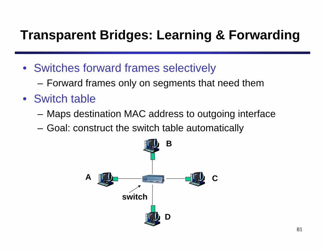
Transparent Bridges: Learning & Forwarding
• Switches forward frames selectively– Forward frames only on segments that need them
• Switch table– Maps destination MAC address to outgoing interface– Goal: construct the switch table automatically
switch
A
B
C
D
82
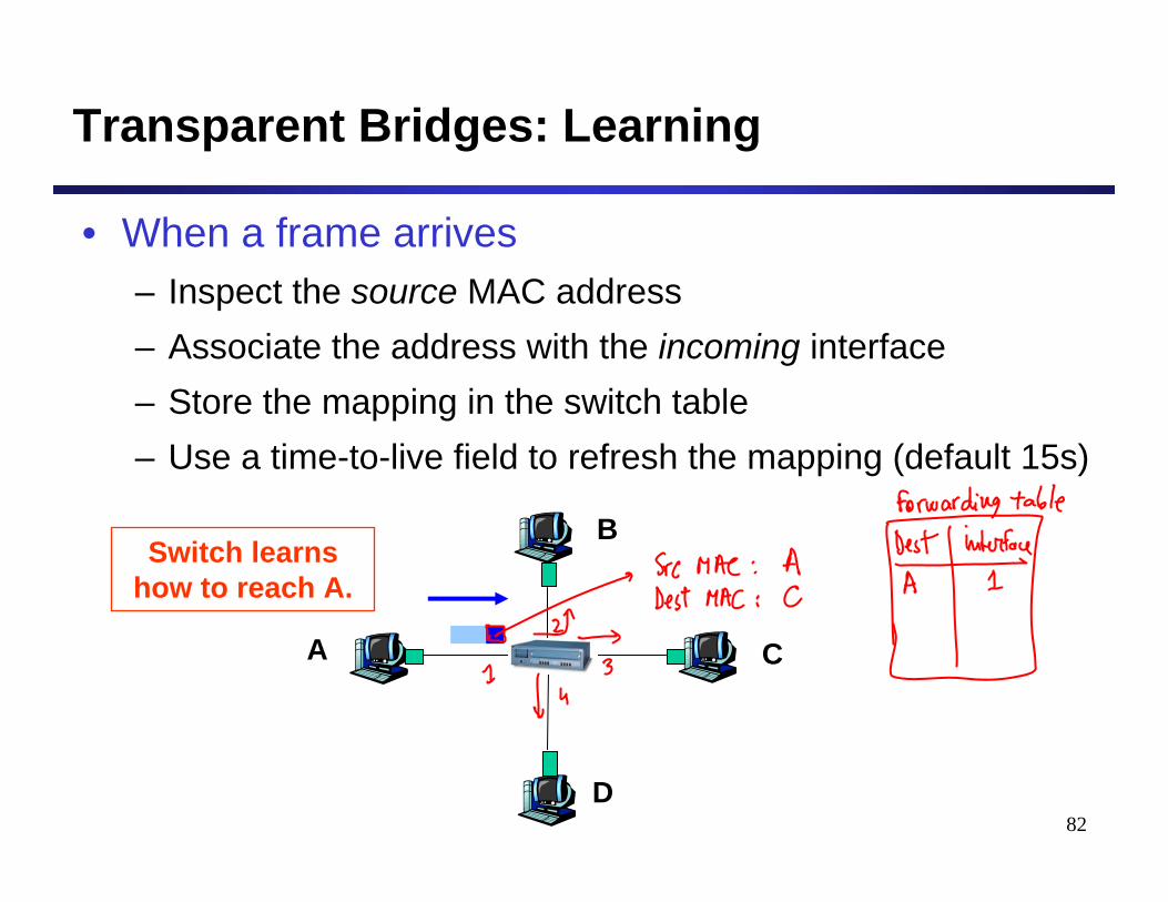
Transparent Bridges: Learning
• When a frame arrives– Inspect the source MAC address– Associate the address with the incoming interface– Store the mapping in the switch table– Use a time-to-live field to refresh the mapping (default 15s)
A
B
C
D
Switch learns how to reach A.
83
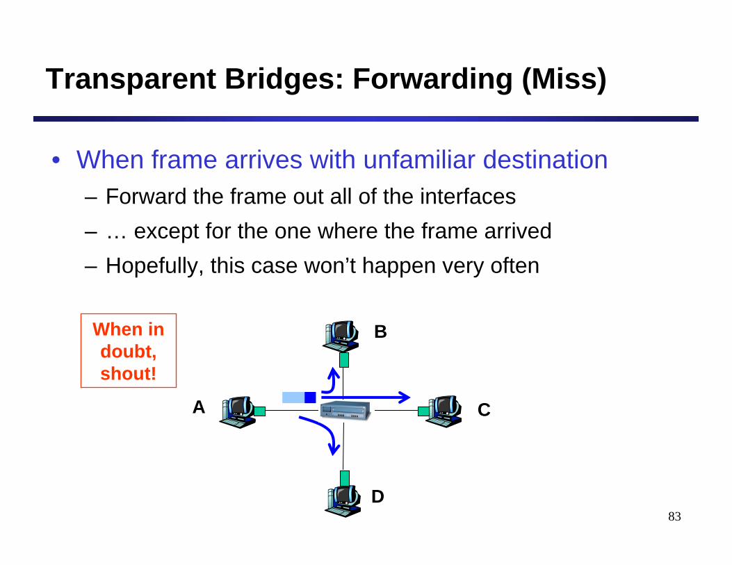
Transparent Bridges: Forwarding (Miss)
• When frame arrives with unfamiliar destination– Forward the frame out all of the interfaces– … except for the one where the frame arrived– Hopefully, this case won’t happen very often
A
B
C
D
When in doubt, shout!
84
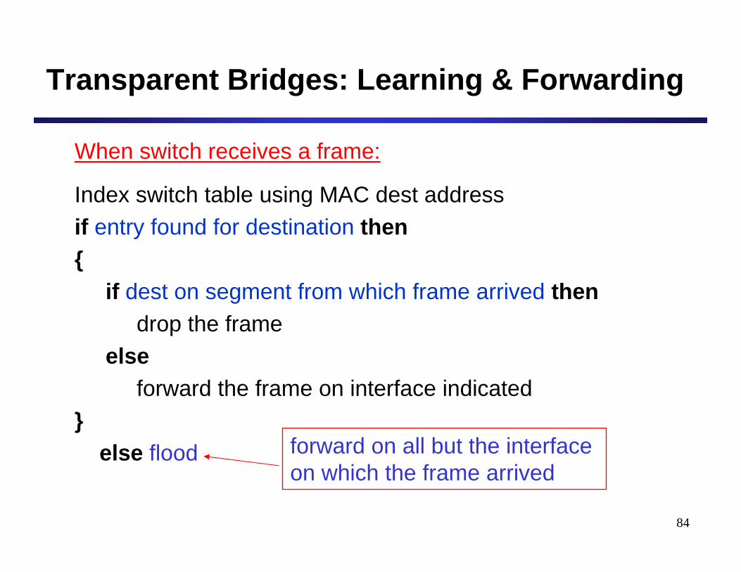
Transparent Bridges: Learning & Forwarding
When switch receives a frame:
Index switch table using MAC dest addressif entry found for destination then{
if dest on segment from which frame arrived thendrop the frame
elseforward the frame on interface indicated
}else flood forward on all but the interface
on which the frame arrived
85
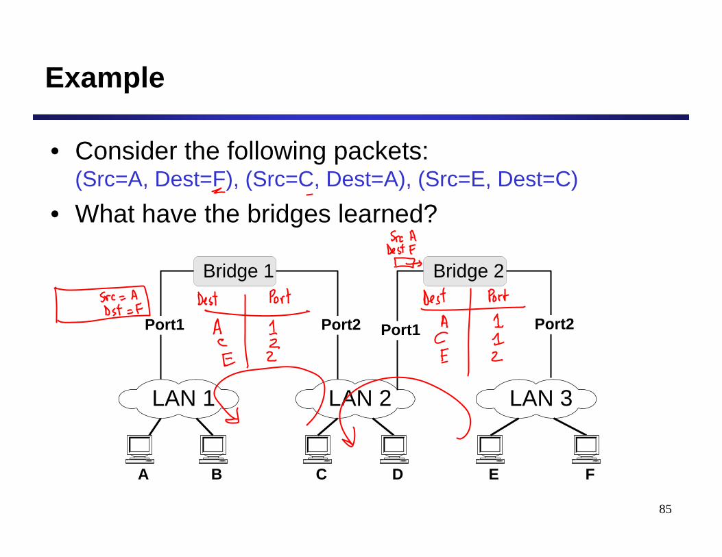
Example
• Consider the following packets: (Src=A, Dest=F), (Src=C, Dest=A), (Src=E, Dest=C)
• What have the bridges learned?
Bridge 1
Port1
LAN 1
A
LAN 2
CB D
LAN 3
E F
Port2
Bridge 2
Port1 Port2
86
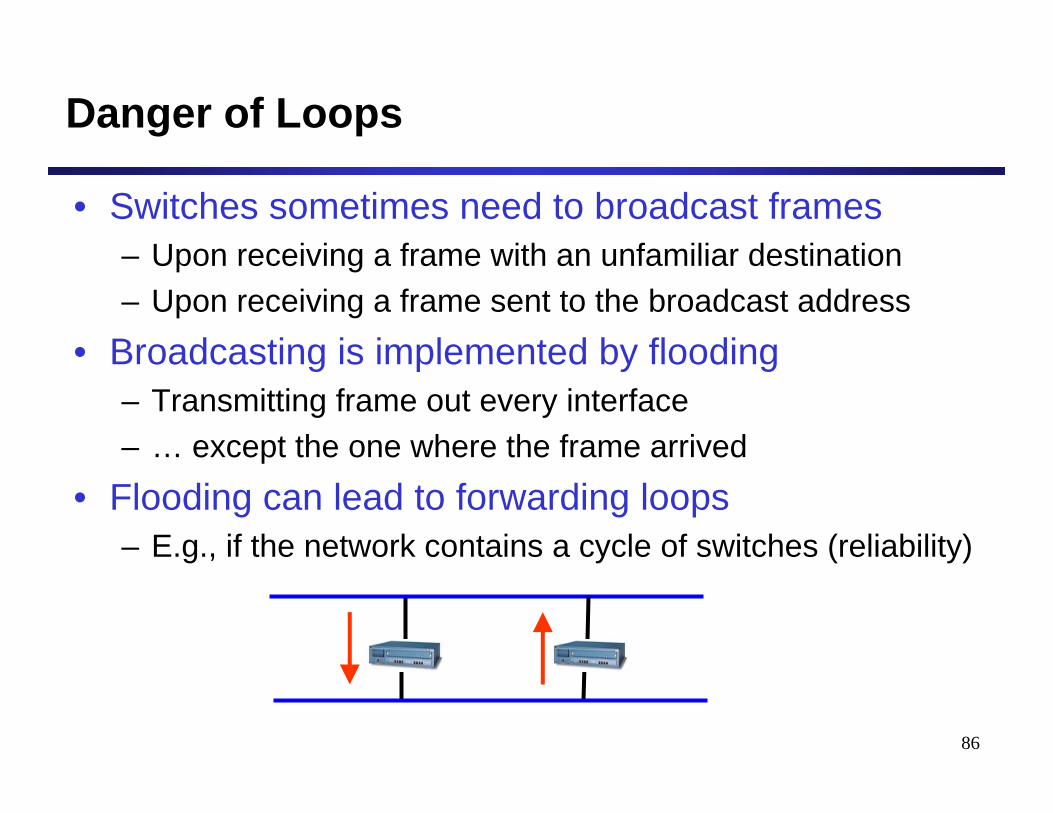
Danger of Loops
• Switches sometimes need to broadcast frames– Upon receiving a frame with an unfamiliar destination– Upon receiving a frame sent to the broadcast address
• Broadcasting is implemented by flooding– Transmitting frame out every interface– … except the one where the frame arrived
• Flooding can lead to forwarding loops– E.g., if the network contains a cycle of switches (reliability)
87
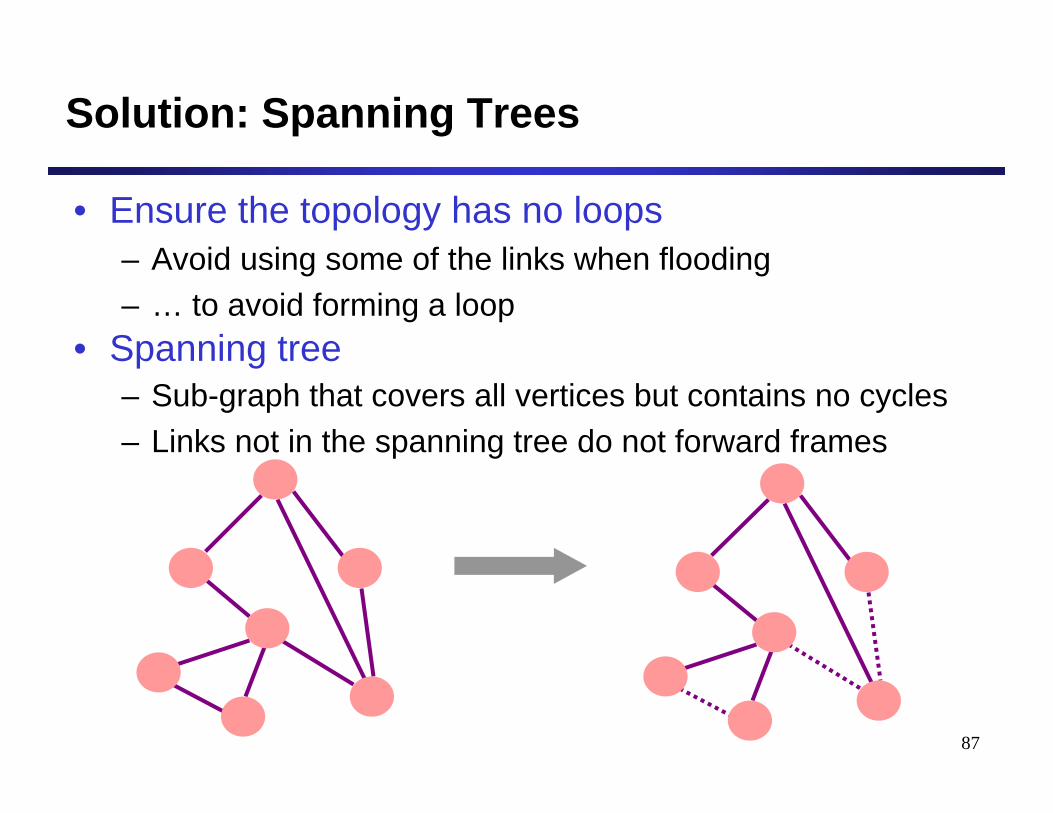
Solution: Spanning Trees
• Ensure the topology has no loops– Avoid using some of the links when flooding– … to avoid forming a loop
• Spanning tree– Sub-graph that covers all vertices but contains no cycles– Links not in the spanning tree do not forward frames
88
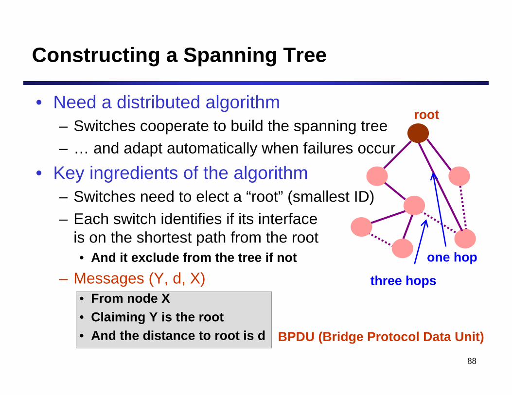
Constructing a Spanning Tree
• Need a distributed algorithm– Switches cooperate to build the spanning tree– … and adapt automatically when failures occur
• Key ingredients of the algorithm– Switches need to elect a “root” (smallest ID)– Each switch identifies if its interface
is on the shortest path from the root• And it exclude from the tree if not
– Messages (Y, d, X)• From node X• Claiming Y is the root• And the distance to root is d
root
one hop
three hops
BPDU (Bridge Protocol Data Unit)
89
Steps in Spanning Tree Algorithm
• Initially, each switch thinks it is the root– Switch sends a message out every interface– … identifying itself as the root with distance 0– Example: switch X announces (X, 0, X)
• Switches update their view of the root– Upon receiving a message, check the root id– If the new id is smaller, start viewing that switch as root
• Switches compute their distance from the root– Add 1 to the distance received from a neighbor– Identify interfaces not on a shortest path to the root– … and exclude them from the spanning tree
90
1
2
3 5
67
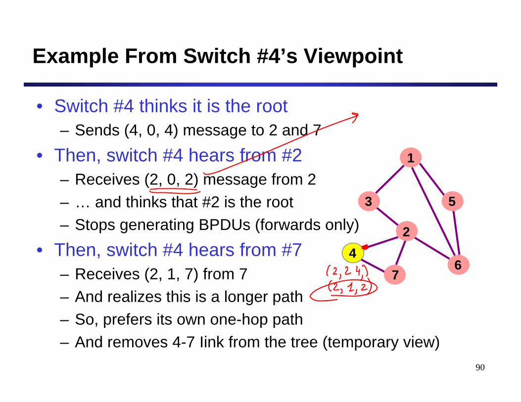
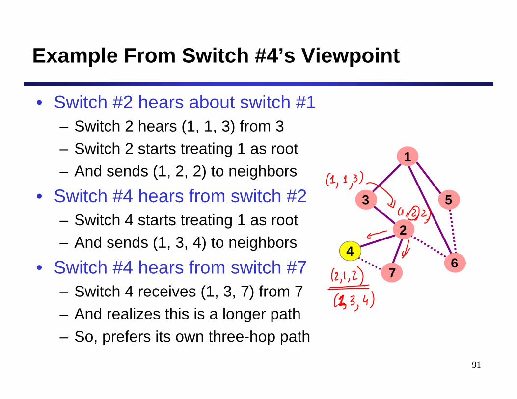
Example From Switch #4’s Viewpoint
• Switch #4 thinks it is the root– Sends (4, 0, 4) message to 2 and 7
• Then, switch #4 hears from #2– Receives (2, 0, 2) message from 2– … and thinks that #2 is the root– Stops generating BPDUs (forwards only)
• Then, switch #4 hears from #7– Receives (2, 1, 7) from 7– And realizes this is a longer path– So, prefers its own one-hop path– And removes 4-7 Iink from the tree (temporary view)
4
91
Example From Switch #4’s Viewpoint
• Switch #2 hears about switch #1– Switch 2 hears (1, 1, 3) from 3– Switch 2 starts treating 1 as root– And sends (1, 2, 2) to neighbors
• Switch #4 hears from switch #2– Switch 4 starts treating 1 as root– And sends (1, 3, 4) to neighbors
• Switch #4 hears from switch #7– Switch 4 receives (1, 3, 7) from 7– And realizes this is a longer path– So, prefers its own three-hop path
1
2
3 5
67
4
92
Robust Spanning Tree Algorithm
• Algorithm must react to failures– Failure of the root node
• Need to elect a new root, with the next lowest identifier– Failure of other switches and links
• Need to recompute the spanning tree• Root switch continues sending messages
– Periodically reannouncing itself as the root (1, 0, 1)• every 2s by default
– Other switches continue forwarding messages• Detecting failures through timeout (soft state!)
– Switch waits to hear from others– Eventually times out and claims to be the root
See Section 3.2.2 in the textbook for details and another example
93
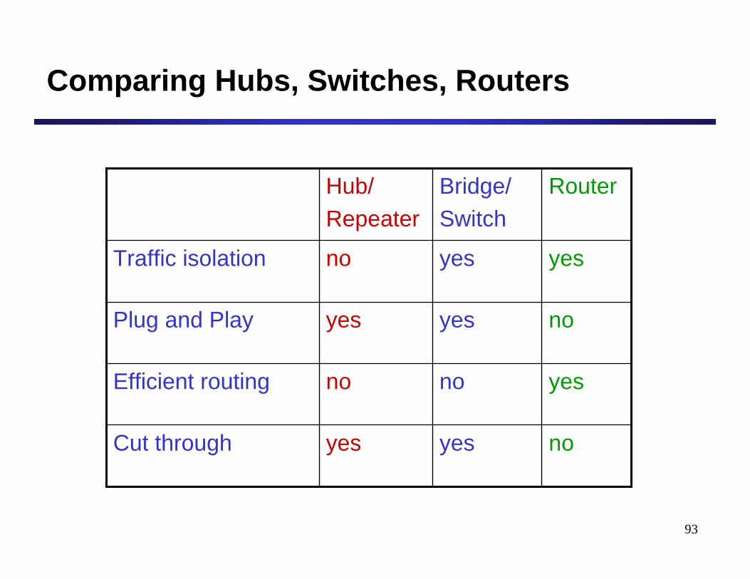
Comparing Hubs, Switches, Routers
noyesyesCut through
yesnonoEfficient routing
noyesyesPlug and Play
yesyesnoTraffic isolation
RouterBridge/Switch
Hub/Repeater
94
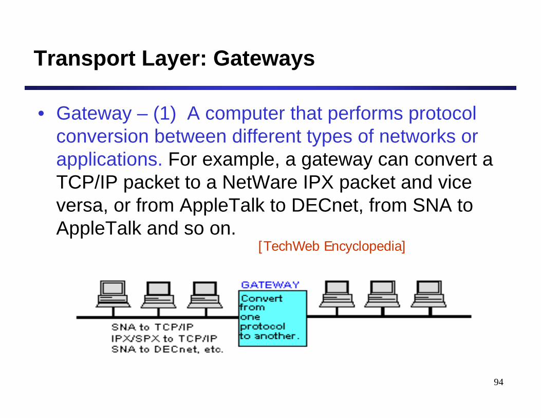
Transport Layer: Gateways
• Gateway – (1) A computer that performs protocol conversion between different types of networks or applications. For example, a gateway can convert a TCP/IP packet to a NetWare IPX packet and vice versa, or from AppleTalk to DECnet, from SNA to AppleTalk and so on.
[TechWeb Encyclopedia]
Network Categories
96
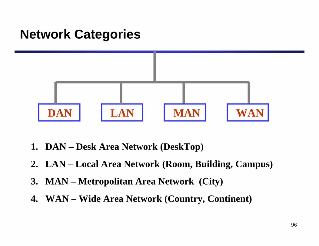
Network Categories
DAN LAN MAN WAN
1. DAN – Desk Area Network (DeskTop)
2. LAN – Local Area Network (Room, Building, Campus)
3. MAN – Metropolitan Area Network (City)
4. WAN – Wide Area Network (Country, Continent)
97
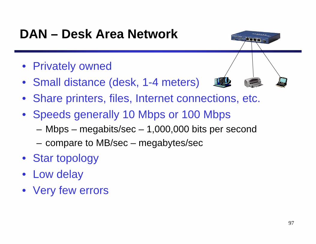
DAN – Desk Area Network
• Privately owned• Small distance (desk, 1-4 meters)• Share printers, files, Internet connections, etc.• Speeds generally 10 Mbps or 100 Mbps
– Mbps – megabits/sec – 1,000,000 bits per second– compare to MB/sec – megabytes/sec
• Star topology• Low delay• Very few errors
98
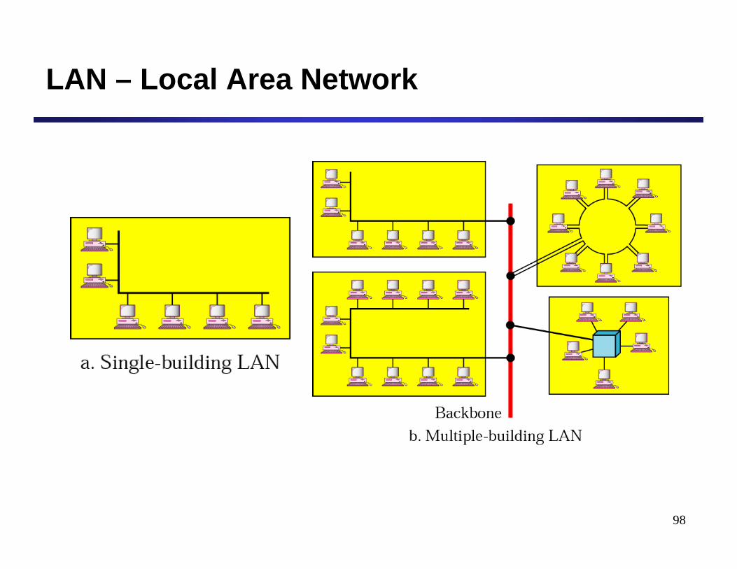
LAN – Local Area Network
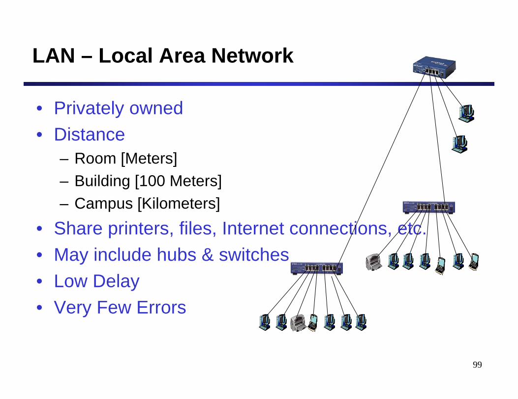
99
LAN – Local Area Network
• Privately owned• Distance
– Room [Meters]– Building [100 Meters]– Campus [Kilometers]
• Share printers, files, Internet connections, etc.• May include hubs & switches• Low Delay• Very Few Errors
100
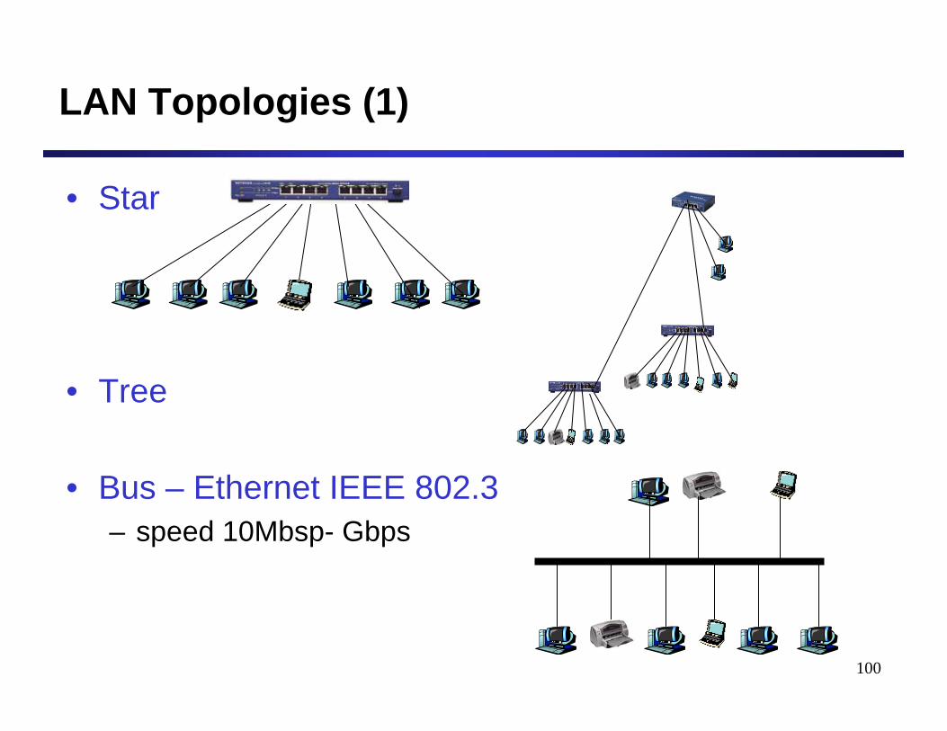
LAN Topologies (1)
• Star
• Tree
• Bus – Ethernet IEEE 802.3– speed 10Mbsp- Gbps
101
LAN Topologies (2)
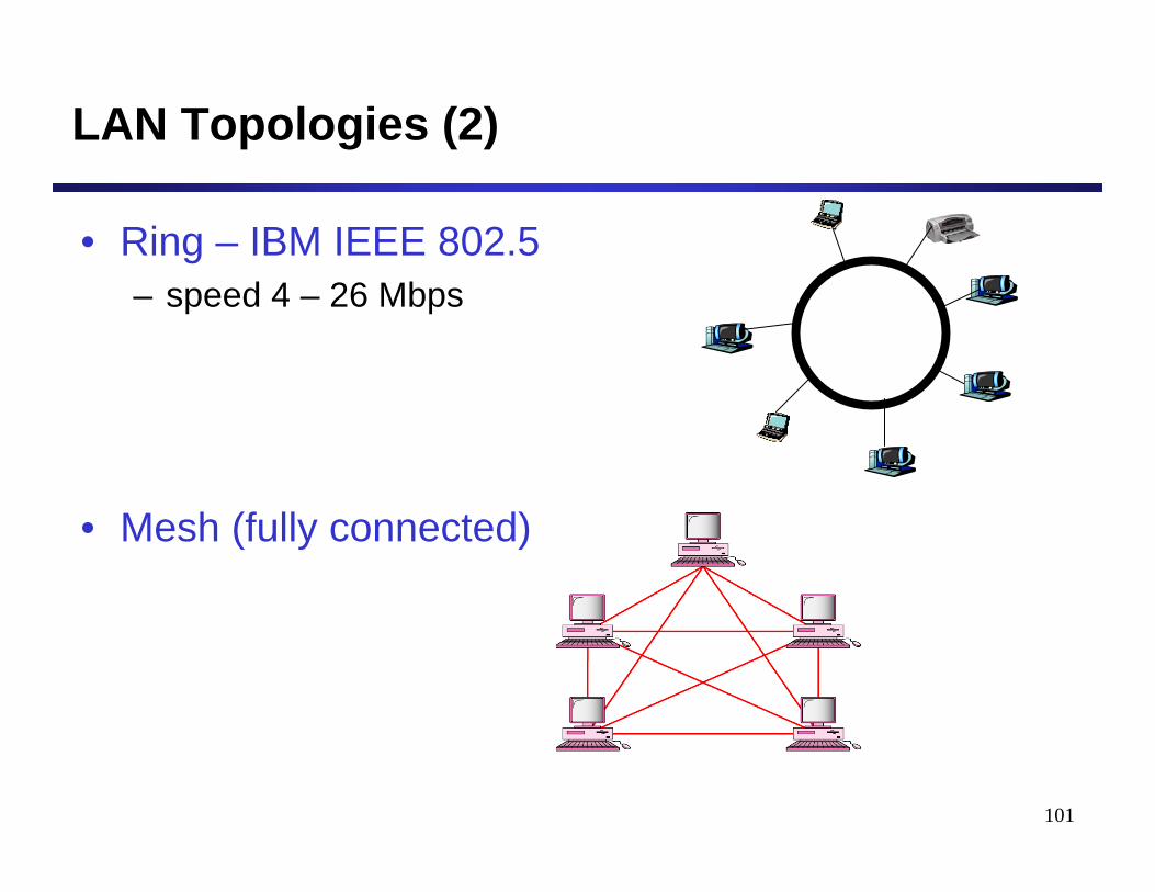
• Ring – IBM IEEE 802.5– speed 4 – 26 Mbps
• Mesh (fully connected)
102
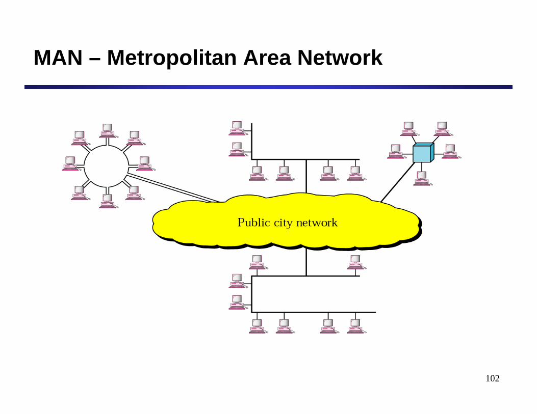
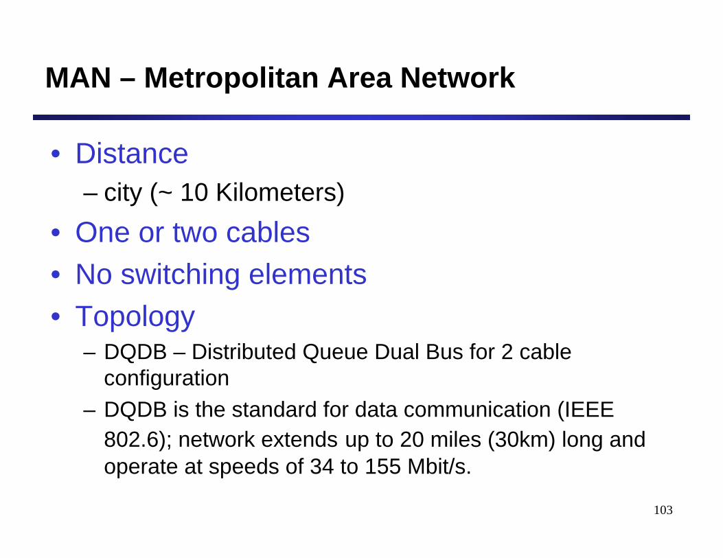
MAN – Metropolitan Area Network
103
MAN – Metropolitan Area Network
• Distance– city (~ 10 Kilometers)
• One or two cables• No switching elements• Topology
– DQDB – Distributed Queue Dual Bus for 2 cable configuration
– DQDB is the standard for data communication (IEEE 802.6); network extends up to 20 miles (30km) long and operate at speeds of 34 to 155 Mbit/s.
104
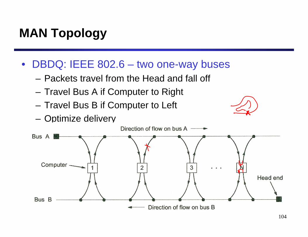
MAN Topology
• DBDQ: IEEE 802.6 – two one-way buses– Packets travel from the Head and fall off– Travel Bus A if Computer to Right– Travel Bus B if Computer to Left– Optimize delivery
105
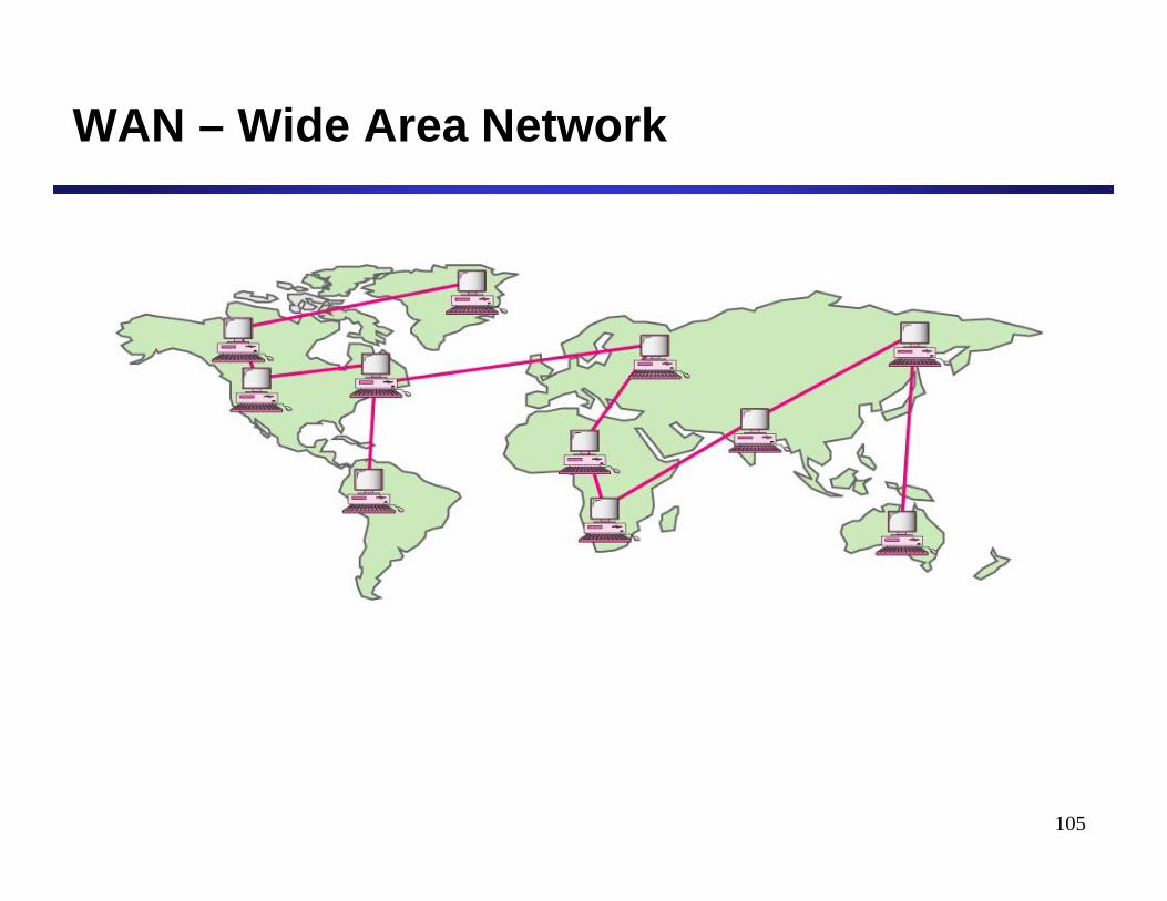
WAN – Wide Area Network
106
WAN – Wide Area Network
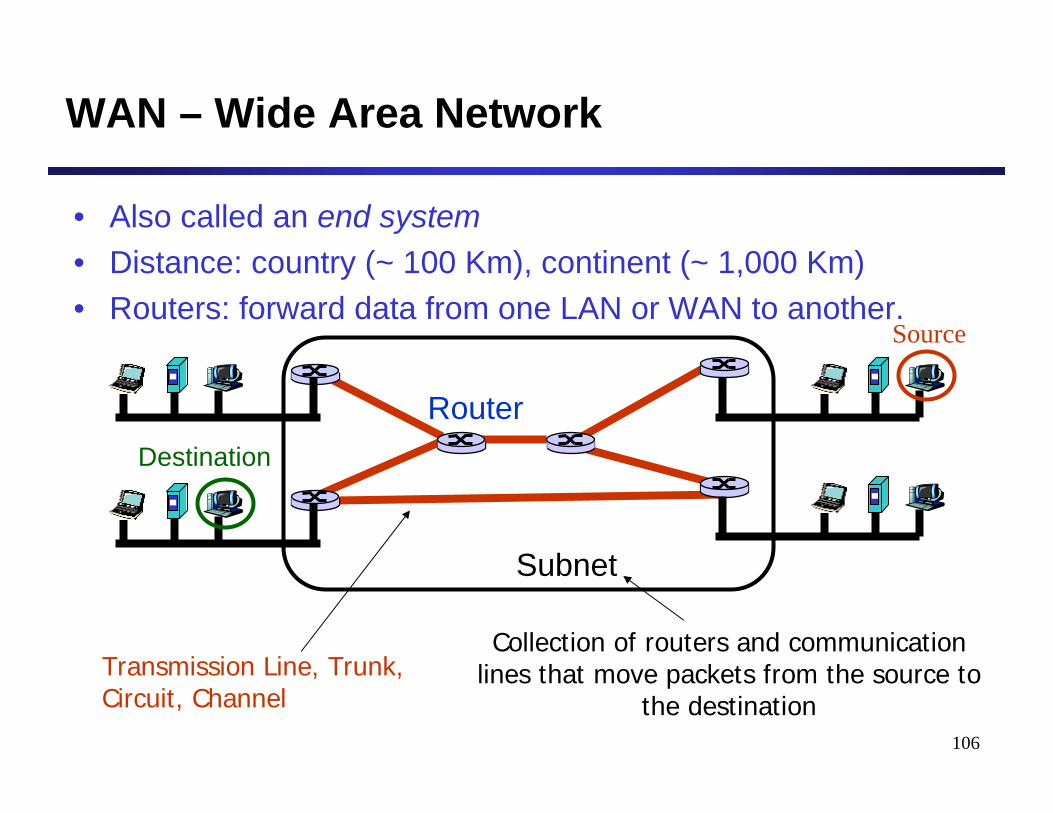
• Also called an end system• Distance: country (~ 100 Km), continent (~ 1,000 Km)• Routers: forward data from one LAN or WAN to another.
Subnet
Router
Transmission Line, Trunk,Circuit, Channel
Collection of routers and communication lines that move packets from the source to
the destination
Source
Destination
107
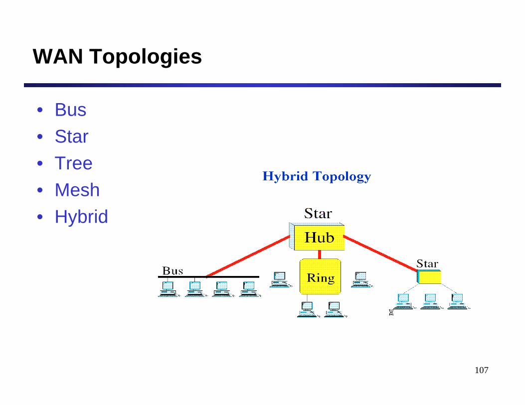
WAN Topologies
• Bus• Star• Tree• Mesh• Hybrid
108
Summary
• Ethernet technology• Shuttling data from one link to another
– Bits, frames, packets, …– Repeaters/hubs, bridges/switches, routers, …
• Key ideas in switches– Cut-through switching– Self learning of the switch table– Spanning trees
• Network Categories– DAN, LAN, MAN, WAN