tcp-ip ethernet comm for 90
TRANSCRIPT

GFK-1541A i
GE Fanuc Automation
Programmable Control Products
TCP/IP Ethernet Communicationsfor the Series 90 PLC
User's Manual
GFK-1541A April 1999

ii
GFL-002
Warnings, Cautions, and Notesas Used in this Publication
Warning
Warning notices are used in this publication to emphasize that hazardous voltages,currents, temperatures, or other conditions that could cause personal injury exist in thisequipment or may be associated with its use.
In situations where inattention could cause either personal injury or damage toequipment, a Warning notice is used.
Caution
Caution notices are used where equipment might be damaged if care is not taken.
NoteNotes merely call attention to information that is especially significant to understanding andoperating the equipment.
This document is based on information available at the time of its publication. While effortshave been made to be accurate, the information contained herein does not purport to cover alldetails or variations in hardware or software, nor to provide for every possible contingency inconnection with installation, operation, or maintenance. Features may be described hereinwhich are not present in all hardware and software systems. GE Fanuc Automation assumes noobligation of notice to holders of this document with respect to changes subsequently made.
GE Fanuc Automation makes no representation or warranty, expressed, implied, or statutorywith respect to, and assumes no responsibility for the accuracy, completeness, sufficiency, orusefulness of the information contained herein. No warranties of merchantability or fitness forpurpose shall apply.
The following are trademarks of GE Fanuc Automation North America, Inc.
Alarm Master Field Control Modelmaster Series 90CIMPLICITY GEnet Motion Mate Series OneCIMPLICITY Control Genius PowerMotion Series SixCIMPLICITY PowerTRAC Genius PowerTRAC ProLoop Series ThreeCIMPLICITY 90–ADS Helpmate PROMACRO VuMasterCIMSTAR Logicmaster Series Five Workmaster
©Copyright 1998 GE Fanuc Automation North America, Inc.All Rights Reserved.
Preface
GFK-1541A iii
Content of This Manual
This manual describes the following Ethernet Interfaces for the Series 90 PLC.
n Series 90-30 PLC TCP/IP Ethernet Interface (IC693CMM321)
n Series 90-30 PLC CPU364 with embedded TCP/IP Ethernet Interface (IC693CPU364)
n Series 90-70 PLC TCP/IP Ethernet Interface (Type 2) (IC697CMM742)
Chapter 1. Introduction: Discusses the TCP/IP Ethernet Interface, its communicationscapabilities, and generally how to get your system running. Also included is a quickguide to the manual.
Chapter 2. Installing the TCP/IP Ethernet Interface: Describes the basic features of eachTCP/IP Ethernet Interface, the installation and power-up of the Interface, and aprocedure for the initial checkout of the Interface on your Ethernet cable.
Chapter 3. Programming Communications Requests: Describes the ladder programmingnecessary for communication between PLCs.
Chapter 4. Ethernet Global Data: Describes Ethernet Global Data.
Chapter 5. Network Administration Support: Describes network address naming, nameresolution, and the multiple gateway feature.
Chapter 6. Troubleshooting: Describes troubleshooting and problem isolation for theEthernet Interface.
Appendix A. Glossary of Terms
Appendix B. Communications Port Characteristics
Appendix C. PC Software Loader
Appendix D. Using the IC697CMM742 with PLC CPUs (Versions 4.12-5.50)

Preface
iv TCP/IP Ethernet Communications for the Series 90 PLC User's Manual–April 1999 GFK-1541A
Related Publications
GFK-1186 TCP/IP Ethernet Communications for the Series 90™ PLC Station Manager Manual
GFK-0262 Series 90™-70 Programmable Controller Installation Manual
GFK-0263 Logicmaster 90™-70 Programming Software User’s Manual
GFK-0265 Series 90™-70 Programmable Controller Reference Manual
GFK-0356 Series 90™-30 Programmable Controller Installation Manual
GFK-0466 Logicmaster 90™-30/20/Micro Programming Software User's Manual
GFK-0467 Series 90™-30/20/Micro Programming Software Reference Manual
GFK-0870 Host Communications Toolkit for C/C++ Applications User’s Manual
GFK-1063 Host Communications Toolkit for Visual Basic Applications User’s Manual
GFK-1026 Host Communications Drivers for Microsoft® Windows® User’s Manual
At GE Fanuc Automation, we strive to produce quality technical documentation. After you haveused this manual, please take a few moments to complete and return the Reader's Comment Cardlocated on the next page.
Contents
GFK-1541A v
Chapter 1 Introduction..................................................................................................... 1-1
The Ethernet Interface................................................................................................... 1-1Capabilities of the Ethernet Interface ..................................................................... 1-2Attachment of the Ethernet Interface to the LAN ................................................... 1-3
Series 90-30 TCP/IP Ethernet Interface........................................................... 1-3Series 90-30 CPU364 Embedded TCP/IP Ethernet Interface ........................... 1-3Series 90-70 TCP/IP Ethernet Interface (Type 2) ............................................ 1-3
The Station Manager Software .............................................................................. 1-5The PC Software Loader ....................................................................................... 1-5
How to Make the System Work .................................................................................... 1-5Quick Guide to the Manual ........................................................................................... 1-6
Chapter 2 Installing the Ethernet Interface..................................................................... 2-1
Section 1: Series 90-30 TCP/IP Ethernet Interface...................................... 2-2Ethernet Interface Hardware Overview ................................................................... 2-2
Board Indicators ................................................................................................... 2-3Restart Pushbutton ................................................................................................ 2-3Serial Ports ........................................................................................................... 2-4
RS-232, RJ-11 Port (Station Manager Port) .................................................... 2-4RS-485, D-type Port (Software Loader Port).................................................. 2-5
AAUI (Transceiver) Port....................................................................................... 2-5Default Station Address Label............................................................................... 2-5Serial Number Label ............................................................................................. 2-5
Procedure 1: Installing the Ethernet Interface in the PLC ............................................ 2-6Equipment Required to Perform the Installation Procedures.................................... 2-6Ethernet Interface Installation ................................................................................. 2-6
Procedure 2: Configuring the Ethernet Interface ......................................................... 2-8Configuring the Interface Using the Logicmaster 90-30 Configuration Software ..... 2-8Configuring the Interface Using Windows-Based Programming Software............... 2-9Configuration Parameters ....................................................................................... 2-9
Ethernet Parameters .............................................................................................. 2-9Serial Port Parameters ......................................................................................... 2-10
Procedure 3: Verifying Proper Power-Up of the Ethernet Interface ............................ 2-11Powering-up the Ethernet Interface....................................................................... 2-11Problems During Power-up................................................................................... 2-11States of the Series 90-30 TCP/IP Ethernet Interface............................................. 2-12
Procedure 4: Pinging TCP/IP Ethernet Interfaces on the Network ............................. 2-14Pinging the Interface from a UNIX® host or a PC Running TCP/IP Software ....... 2-14
Determining If an IP Address Has Already Been Used.................................. 2-14
Section 2: Series 90-30 CPU364 with Embedded TCP/IPEthernet Interface ..........................................................................................2-15
Ethernet Interface Hardware Overview ................................................................. 2-15Board Indicators ................................................................................................. 2-16Ethernet Restart Pushbutton ................................................................................ 2-16RS-232, RJ-11 Port ............................................................................................. 2-17Ethernet Ports ..................................................................................................... 2-17

Contents
vi TCP/IP Ethernet Communications for the Series 90 PLC User's Manual–April 1999 GFK-1541A
AAUI (Transceiver) Port .............................................................................. 2-1810BaseT, RJ-45 Port .................................................................................... 2-18
D ........................................................................................................................ 2-18Serial Number Label ........................................................................................... 2-18Replaceable Surface Mount Fuse........................................................................ 2-18
Removing and Installing the Fuse................................................................. 2-18Procedure 1: Installing the Ethernet Interface in the PLC .......................................... 2-19
Equipment Required to Perform the Installation Procedures.................................. 2-19Ethernet Interface Installation ............................................................................... 2-19
Procedure 2: Configuring the Ethernet Interface ....................................................... 2-21Configuring the Interface Using the Logicmaster 90-30 Configuration Software ... 2-21Configuring the Interface Using Windows-Based Programming Software............. 2-22Configuration Parameters ..................................................................................... 2-22
Ethernet Parameters ............................................................................................ 2-22Serial Port Parameters ......................................................................................... 2-24
Procedure 3: Verifying Proper Power-Up of the Ethernet Interface ............................ 2-25Powering-up the Ethernet Interface....................................................................... 2-25Problems During Power-up................................................................................... 2-25States of the Series 90-30 CPU364 with Embedded TCP/IP Ethernet Interface...... 2-26
Procedure 4: Pinging TCP/IP Ethernet Interfaces on the Network ............................. 2-28Pinging the Interface from a UNIX® Host or a PC Running TCP/IP Software ...... 2-28
Determining If an IP Address Has Already Been Used.................................. 2-28
Section 3: Series 90-70 TCP/IP Ethernet Interface (Type 2) ......................2-29Ethernet Interface Hardware Overview ................................................................. 2-29
Board Indicators ................................................................................................. 2-30Restart Pushbutton .............................................................................................. 2-30Service Option Connector ................................................................................... 2-31Serial Ports ......................................................................................................... 2-32
RS-232, RJ-11 Port ...................................................................................... 2-32RS-485, D-Type Port (Software Loader Port) ............................................... 2-32
Ethernet Ports ..................................................................................................... 2-3210BaseT, RJ-45 Port .................................................................................... 2-32AUI Port ...................................................................................................... 2-3210Base2, BNC Port ...................................................................................... 2-32
Default Station Address Label............................................................................. 2-33Disable Onboard 10Base2 Port Jumper................................................................ 2-33Replaceable +12VDC Fuse ................................................................................. 2-33
Procedure 1: Installing the Ethernet Interface in the PLC .......................................... 2-34Equipment Required to Perform the Installation Procedures.................................. 2-34Ethernet Interface Installation ............................................................................... 2-35
Procedure 2: Configuring the Ethernet Interface ....................................................... 2-36Configuring the Interface Using Logicmaster 90-70 Configuration Software......... 2-36Configuring the Interface Using Windows-Based Programming Software............. 2-37Configuration Parameters ..................................................................................... 2-37
Ethernet Parameters ............................................................................................ 2-37Serial Port Parameters ......................................................................................... 2-39

Contents
GFK-1541A Contents vii
Procedure 3: Verifying Proper Power-Up of the Ethernet Interface ............................ 2-40Powering-up the Ethernet Interface....................................................................... 2-40Problems During Power-up................................................................................... 2-40States of the Series 90-70 TCP/IP Ethernet Interface (Type 2)............................... 2-41
Procedure 4: Pinging TCP/IP Ethernet Interfaces on the Network ............................. 2-43Pinging the Interface from a UNIX® Host or a PC Running TCP/IP Software ...... 2-43
Determining If an IP Address Has Already Been Used.................................. 2-43
Chapter 3 Programming Communications Requests...................................................... 3-1
Section 1: The Communications Request ..................................................... 3-2Structure of the Communications Request..................................................................... 3-2
COMMREQ Function Block .................................................................................. 3-3COMMREQ Command Block................................................................................ 3-3Channel Commands................................................................................................ 3-3
Advantages of Channel Commands ................................................................ 3-3Status Data ............................................................................................................. 3-4The Logic Program Controlling Execution of the COMMREQ Function Block....... 3-4
Operation of the Communications Request.................................................................... 3-5
Section 2: COMMREQ Function Block and Command Block ................... 3-6The COMMREQ Function Block.................................................................................. 3-6The COMMREQ Command Block ............................................................................... 3-7
Section 3: Channel Commands..................................................................... 3-9Aborting and Re-tasking a Channel......................................................................... 3-9Retrieving Detailed Status on the Channel ............................................................ 3-10Specifying a Network Address.............................................................................. 3-10
Establish Read Channel (2003) ................................................................................... 3-11Example 1 Command Block–Basic Example ................................................ 3-11Example 2 Command Block–Example using a Network Address name ......... 3-21
Send Information Report (2010) ................................................................................. 3-23Example1 Command Block–Basic Example ................................................. 3-23Example 2 Command Block–Example using a Network Address name ......... 3-26
Abort Channel (2001) ................................................................................................. 3-28Example Command Block ............................................................................ 3-28
Retrieve Detailed Channel Status (2002)..................................................................... 3-29Example Command Block ............................................................................ 3-29
Section 4: Status Data ..................................................................................3-31Types of Status Data................................................................................................... 3-31Description of the Status Data..................................................................................... 3-32
OK Output of the COMMREQ Function Block (Series 90-70 PLCs Only)............ 3-32FT Output of the COMMREQ Function Block...................................................... 3-32Status Bits ............................................................................................................ 3-32
Each channel has a dedicated pair of bits as follows:............................................ 3-34

Contents
viii TCP/IP Ethernet Communications for the Series 90 PLC User's Manual–April 1999 GFK-1541A
Communications Status Words ............................................................................. 3-35Minor Error Codes...................................................................................................... 3-37
Section 5: Controlling Communications in the Ladder Program...............3-40Essential Elements of the Ladder Program .................................................................. 3-40Troubleshooting Your Ladder Program....................................................................... 3-43
FT Output is ON ................................................................................................. 3-43COMMREQ Status Word is Zero (0) and FT Output is OFF................................ 3-43COMMREQ Status Word is Not One (1)............................................................. 3-44
Monitoring the Communications Channel ................................................................... 3-44Monitoring the COMMREQ Status Word............................................................ 3-44Monitoring the Channel Error Bit ........................................................................ 3-44Monitoring the Data Transfer Bit......................................................................... 3-45
Sequencing Communications Requests ....................................................................... 3-45Managing Channels and TCP Connections.................................................................. 3-45
In Certain Conditions TCP Connections Can Be Totally Consumed..................... 3-45Use “Channel Re-Tasking” To Avoid Using Up TCP Connections ...................... 3-46How To Re-Task a Channel ................................................................................ 3-46
Chapter 4 Ethernet Global Data ...................................................................................... 4-1
Section 1: Overview of EGD ......................................................................... 4-2Producer ....................................................................................................................... 4-2
Configuring the Producer ID .......................................................................... 4-3Consumer ..................................................................................................................... 4-3Exchange...................................................................................................................... 4-4
Configuring the Exchange .............................................................................. 4-4Asynchronous Operation of EGD.................................................................................. 4-5Effect of PLC Modes and Actions on EGD Operations ................................................. 4-6Configuration Planning................................................................................................. 4-7
Producer and Consumer Periods for PLCs .............................................................. 4-7Exchange Limitations and Recommendations ......................................................... 4-7
Maximum Number of Exchanges ................................................................... 4-7Maximum Data Size of an Exchange .............................................................. 4-7Number of Variables ...................................................................................... 4-7Allowable Data Types in Exchanges............................................................... 4-8Producer and Consumer Period Ranges........................................................... 4-8Effect of Enabling User Interrupts .................................................................. 4-8Update Timeout Period................................................................................... 4-8
PLC Timing Considerations when using EGD ........................................................ 4-9Naming Conventions .................................................................................................. 4-10Before You Configure EGD Exchanges ...................................................................... 4-11
Record Your EGD System Information................................................................. 4-11Recording Exchange Information.......................................................................... 4-12
Record Your Produced Exchange Information ..................................................... 4-12Record Your Consumed Exchange Information ................................................... 4-12

Contents
GFK-1541A Contents ix
Section 2: Configuring EGD ........................................................................4-13Exchange Definitions.................................................................................................. 4-13
Produced Data Exchange Definition ..................................................................... 4-13Consumed Data Exchange Definition ................................................................... 4-14
Configuring Ethernet Global Data............................................................................... 4-16Example 1: EGD Configuration Using IP Addresses to Identify Consumers ................ 4-17Example 2: EGD Configuration Using a Group ID to Identify Consumers................... 4-18Example 3: EGD Configuration Using a Symbolic Name to Identify Consumers......... 4-19
Valid PLC Memory Types Used with EGD .......................................................... 4-20
Section 3: Adapter Names, Aliases, and Groups...........................................4-21Setting Adapter Names and Aliases in the Windows-Based Programming Software .... 4-21
Configuring the Ethernet Interface Adapter Name................................................. 4-21Setting Aliases for Remote Network Adapters ...................................................... 4-21
Group Usage............................................................................................................... 4-22
Section 4: Exchange Status Word................................................................4-23
Section 5: Simple Network Time Protocol (SNTP) .....................................4-25Timestamping EGD Exchanges .................................................................... 4-25Configuring an Ethernet Interface for SNTP ................................................. 4-25Normal SNTP Operation .............................................................................. 4-25Multiple SNTP Servers ................................................................................ 4-26Loss or Absence of SNTP Timing Signals .................................................... 4-26
Chapter 5 Network Administration Support................................................................... 5-1
IP Addressing ............................................................................................................... 5-1IP Addresses Reserved for Private Networks .......................................................... 5-2Multicast IP Addresses ........................................................................................... 5-2
Gateways...................................................................................................................... 5-3Example: Networks Connected by a Gateway ................................................. 5-3
Subnets and Multiple Gateways .................................................................................... 5-4Subnet Addressing and Subnet Masks............................................................. 5-4Example: Network Divided into Two Subnets................................................. 5-5
Configuring Multiple Gateways .................................................................................... 5-6Example: Configuring Multiple Gateways ..................................................... 5-6Module Configuration for the Ethernet Interface in PLC B.............................. 5-7PLC Routing Table to Configure Multiple Gateways for PLC B and PLC C.... 5-7
Network Address Naming Architecture......................................................................... 5-8Name Assignment .................................................................................................. 5-8
DDP Name Assignment ........................................................................................ 5-8Default DDP Network Address Name............................................................. 5-8Assigned DDP Network Address Name.......................................................... 5-8
Local Name Table Name Assignment.................................................................... 5-9DNS Name Assignment ........................................................................................ 5-9
Name Resolution .................................................................................................... 5-9Local Name Table Name Resolution ................................................................... 5-10DDP Name Resolution........................................................................................ 5-10
Contents
x TCP/IP Ethernet Communications for the Series 90 PLC User's Manual–April 1999 GFK-1541A
DNS Name Resolution........................................................................................ 5-10Name Usage ......................................................................................................... 5-10
MAC Addresses.......................................................................................................... 5-11
Chapter 6 Troubleshooting .............................................................................................. 6-1
Diagnostic Tools Available for Troubleshooting ........................................................... 6-1What to do if you Cannot Solve the Problem................................................................. 6-2PLC Fault Table ........................................................................................................... 6-2
Appendix A Glossary ...........................................................................................................A-1
Commonly Used Acronyms and Abbreviations ............................................................ A-1Glossary of Terms ....................................................................................................... A-2
Appendix B Communications Ports Characteristics ..........................................................B-1
RS-232, RJ-11 Serial Port............................................................................................ B-2Port Settings .......................................................................................................... B-2Port Pinouts........................................................................................................... B-2Cable..................................................................................................................... B-3
RS-485, 15-Pin, D-Type Port....................................................................................... B-4Port Settings .......................................................................................................... B-4Port Pinouts........................................................................................................... B-4Part Numbers for GE Fanuc Cables and Converters ............................................... B-5Port Cable ............................................................................................................. B-5
10BaseT Port............................................................................................................... B-6Port Pinouts........................................................................................................... B-6Network Connection.............................................................................................. B-7
10Base2 Port ............................................................................................................... B-8Port Pinouts........................................................................................................... B-8Network Connections ............................................................................................ B-9
AAUI Port................................................................................................................. B-10Ethernet AAUI Port Pinouts ................................................................................ B-10Transceiver Configurations.................................................................................. B-11
AUI Port.................................................................................................................... B-13Port Pinouts......................................................................................................... B-13AUI (Transceiver Cable) ..................................................................................... B-14Transceiver Description....................................................................................... B-14

Contents
GFK-1541A Contents xi
Appendix C PC Software Loader........................................................................................C-1Updating Firmware Under Windows .................................................................... C-1
To install the new firmware, perform the following steps ............................... C-1Restarting an Interrupted Firmware Upgrade.................................................. C-3
Updating Firmware Under DOS and Windows 3.xx.............................................. C-3To install the new firmware, perform the following steps ............................... C-4
Appendix D Using the IC697CMM742 with PLC CPUs (Versions 4.12 - 5.50) ................D-1
Ethernet Interface Installation and Configuration ......................................................... D-1Alternate Procedure 2: Configuring the Ethernet Interface (with PLC CPU versions4.12 through 5.50) ................................................................................................. D-2
Ethernet Interface Operational Restrictions .................................................................. D-6Startup .................................................................................................................. D-6Station Manager .................................................................................................... D-6Software Loader .................................................................................................... D-7

Contents
xii TCP/IP Ethernet Communications for the Series 90 PLC User's Manual–April 1999 GFK-1541A
Figure 1-1. Ethernet Communications System ......................................................................................... 1-2
Figure 2-1. Series 90-30 TCP/IP Ethernet Interface ................................................................................. 2-2
Figure 2-2. States of the Series 90-30 TCP/IP Ethernet Interface............................................................ 2-12
Figure 2-3. Series 90-30 CPU364 .......................................................................................................... 2-15
Figure 2-4. States of the Series 90-30 CPU364 with Embedded TCP/IP Ethernet Interface .................... 2-26
Figure 2-5. Series 90-70 Ethernet Interface (Type 2).............................................................................. 2-29
Figure 2-6. States of the Series 90-70 TCP/IP Ethernet Interface (Type 2) ............................................. 2-41
Figure 3-1. Elements of the Communications Request ............................................................................. 3-2
Figure 3-2. Operation of the Communications Request for an Establish Read Channel Command............ 3-5
Figure 3-3. Format of the COMMREQ Status Word (CRS Word).......................................................... 3-35
Figure 3-4. Format of the Detailed Channel Status Words (DCS Words)................................................ 3-35
Figure 4-1. Successful Operation of EGD................................................................................................ 4-5
Figure 4-2. The CPU and Ethernet Interface Use Shared Internal Memory for EGD................................. 4-9
Figure 5-1. IP Address Format for Network Classes A, B, C.................................................................... 5-1
Figure 5-2. Connecting Two Networks with a Gateway ........................................................................... 5-3
Figure 5-3. Network Divided into Two Subnets ....................................................................................... 5-5
Figure 5-4. Configuring Multiple Gateways............................................................................................. 5-6
Figure B-1. Station Manager Serial Port (RS-232) .................................................................................. B-2
Figure B-2. Serial Cable (IC693CBL316A) to Connect the Personal Computer to theRJ-11, RS-232 Serial Port .............................................................................................. B-3
Figure B-3. Software Loader Cable Assembly (IC690ACC901).............................................................. B-5
Figure B-4. Connection to a 10BaseT Network....................................................................................... B-7
Figure B-5. Connection to a 10Base2 Network with “T” Connector........................................................ B-9
Figure B-6. Connection to a 10Base2 Network with “F” Connector ........................................................ B-9
Figure B-7. 10Base2 Transceiver Configuration using BNC “T” Connector (IC649AEA101) .............. B-11
Figure B-8. 10BaseT Transceiver Configuration (IC649AEA102) ........................................................ B-12
Figure B-9. Transceiver Cable Connection ........................................................................................... B-14
Figure B-10. 10Base2 Transceiver Configuration ................................................................................. B-14

Contents
GFK-1541A Contents xiii
Table 2-1. Problems During Power-Up.................................................................................................. 2-13
Table 2-2. Problems During Power-Up.................................................................................................. 2-27
Table 2-3. Problems During Power-Up.................................................................................................. 2-42
Table 3-1. Time Unit Values for Read/Write Repetition Period.............................................................. 3-12
Table 3-2. Series 90 PLC Memory Types .............................................................................................. 3-13
Table 3-3. Ethernet Interface Status Bits................................................................................................ 3-33
Table 3-4. Major Error Codes ................................................................................................................ 3-36
Table 3-5. Minor Error Codes for Major Error Codes 05H (at Remote Server PLC) and 85H(at Client PLC).............................................................................................................. 3-37
Table 3-5. Minor Error Codes for Major Error Codes 5H and 85H (Continued) ..................................... 3-38
Table 3-6. Minor Error Codes for Major Error Code 11H (at Remote Server PLC) ................................ 3-38
Table 3-7. Minor Error Codes for Major Error Code 90H (at Client PLC).............................................. 3-39
Table 4-1. Effect of PLC Modes and Actions on EGD Operations ........................................................... 4-6
Naming Conventions – EXAMPLE........................................................................................................ 4-10
Producer/Consumer Information for Entire EGD System – EXAMPLE .................................................. 4-11
Produced Exchanges Information – EXAMPLE ..................................................................................... 4-12
Consumed Exchanges Information – EXAMPLE ................................................................................... 4-12
Producer/Consumer Information for Entire EGD System – EXAMPLE 1 ............................................... 4-17
Produced Exchange Information – EXAMPLE 1.................................................................................... 4-17
Variable List for Produced Exchange – EXAMPLE 1............................................................................. 4-17
Consumed Exchange Information – EXAMPLE 1.................................................................................. 4-17
Variable List for Consumed Exchange – EXAMPLE 1........................................................................... 4-17
Producer/Consumer Information for Entire EGD System – EXAMPLE 2 ............................................... 4-18
Produced Exchange Information – EXAMPLE 2.................................................................................... 4-18
Variable List for Produced Exchange – EXAMPLE 2............................................................................. 4-18
Consumed Exchanges Information – EXAMPLE 2................................................................................. 4-18
Variable List for Consumed Exchanges – EXAMPLE 2 ......................................................................... 4-18
Producer/Consumer Information for Entire EGD System – EXAMPLE 3 ............................................... 4-19
Produced Exchanges Information – EXAMPLE 3 .................................................................................. 4-19
Variable List for Produced Exchanges – EXAMPLE 3 ........................................................................... 4-19
Consumed Exchanges Information – EXAMPLE 3................................................................................. 4-20
Variable List for Consumed Exchanges – EXAMPLE 3 ......................................................................... 4-20
Table 4-2. PLC Memory Types for EGD Commands............................................................................. 4-20
Table 4-3. Exchange Status Word Error Codes ...................................................................................... 4-23
Table 4-3. Exchange Status Word Error Codes - Continued ................................................................... 4-24
Table 6-1. PLC Fault Table Descriptions ................................................................................................. 6-4

Contents
xiv TCP/IP Ethernet Communications for the Series 90 PLC User's Manual–April 1999 GFK-1541A
Table 6-1. PLC Fault Table Descriptions (Continued).............................................................................. 6-5
Table B-1. Station Manager Serial Port Pinouts ...................................................................................... B-2
Table B-2. Serial Cable (IC693CBL316A) Connector Pinouts ................................................................ B-3
Table B-3. Software Loader Port Pinout ................................................................................................. B-4
Table B-4. Cables for Connecting the 15-Pin, D-Type, RS-485 Port to the RS-232 Port on Your PC ...... B-5
Table B-5. 10BaseT Port Pinouts............................................................................................................ B-6
Table B-6. 10Base2 Port Pinouts ............................................................................................................ B-8
Table B-7. Pinouts of the AAUI Port .................................................................................................... B-10
Table B-8. Pinouts of the AUI Port....................................................................................................... B-13

GFK-1541A 1-1
Introduction
This manual describes the following Ethernet Interfaces for the Series 90 PLC:
� Series 90-30 PLC TCP/IP Ethernet Interface (IC693CMM321)
� Series 90-30 PLC CPU364 with embedded TCP/IP Ethernet Interface (IC693CPU364)
� Series 90-70 PLC TCP/IP Ethernet Interface (Type 2) (IC697CMM742)
The general term, Ethernet Interface, will be used in this manual except when differences in theInterfaces require the more specific terms.
This chapter provides an overview of the Ethernet Interface and covers the following topics:
� The Ethernet Interface� How to Make the System Work� Quick Guide to the Manual
The Ethernet Interface
The Ethernet Interface enables Series 90 PLCs to communicate with other Series 90 PLCs, withLogicmaster™ 90 TCP/IP Ethernet (IC641SWP316 or IC641SWP716), with Windows®-basedPLC programming software, and with applications developed using the Host CommunicationsToolkit, such as CIMPLICITY® HMI. GE Fanuc Automation – NA offers the HostCommunications Toolkit separately from the Ethernet Interface.
The Ethernet Interfaces described in this manual have “client/server” capability. As a “client” theInterfaces can initiate communications with other Series 90 PLCs containing Ethernet Interfaces.This is done from the PLC ladder program using the COMMREQ function. As a “server” theInterfaces respond to requests from other devices such as Logicmaster 90 TCP/IP Ethernet, a Hostcomputer running a Host Communications Toolkit application, or another Series 90 PLC acting asa “client”. No PLC programming is required for server operation.
Figure 1-1 illustrates a basic Ethernet Communications System.
® Windows is a registered trademark of Microsoft Corporation.
1Chapter

1-2 TCP/IP Ethernet Communications for the Series 90 PLC User's Manual – April 1999 GFK-1541A
1
TransceiverTransceiver
InterfaceEthernet
Series 90-70PLC
Network
Transceiver
Connection
EthernetCable
InterfaceEthernet
NetworkTransceiver
Connection
Windows-based programmer orLogicmaster 90 TCP/IP
Transceiver
Series 90-30PLC
it
Ethernet running on a PC
Host Computer or
Toolkit Application
Control Device Running aHost Communications
Series 90-30PLC
a45693
EmbeddedEthernet Interface
CPU 364 with
Figure 1-1. Ethernet Communications System
Capabilities of the Ethernet Interface
The Ethernet Interface brings to your PLC a great deal of capability. It will allow you to:
� Become operational quickly. The Ethernet Interface is made operational with very littleeffort. You need only install the Interface in the PLC rack or baseplate and use the PLCprogramming software to store basic configuration information to the module to make thebasic server capability functional. Client capability, the capability to initiate communications,can be added using the COMMREQ function in the ladder program.
� Directly attach your PLC to an Ethernet network. The Ethernet Interface allows you todirectly attach the Series 90 PLC to an Ethernet LAN via the built-in network ports or via auser-supplied transceiver and AUI or AAUI cable, and to communicate with host computersand other Series 90 PLCs on the local network.
� Ethernet Global Data. (Series 90-30 CPU364 and Series 90-70 Ethernet Interface (Type 2)only.) When used with the latest Series 90 CPUs, the Ethernet Interface provides highlyefficient periodic data transfer between PLCs using Ethernet Global Data exchanges.
� Transfer data between PLCs. The Ethernet Interface provides client capability, the capabilityto initiate communications to other Series 90 Ethernet Interfaces, using COMMREQ functionsin the ladder program.
� Access data using a Host computer. Computer applications which use the GE Fanuc HostCommunications Toolkit can access data within the Series 90 PLC through the servercapability of the Ethernet Interface. Supported computer operating systems includeWindows®, Windows NT®, HP-UX 9000, DEC VAX/VMS™, and DEC AlphaAXP/VMS™.
� Communicate simultaneously to multiple devices. The multiplexing capabilities of theEthernet Interface, along with Ethernet network’s high capacity, allow the PLC tocommunicate with several other devices at the same time.
®Windows and Windows NT are registered trademarks of Microsoft Corporation.™DEC, VAX, Alpha AXP, and VMS are trademarks of Digital Equipment Corporation.

GFK-1541A Chapter 1 Introduction 1-3
1
� Maintain compatibility with other GE Fanuc devices, as well as with devices from othervendors. The GE Fanuc Series 90-30 Ethernet Interface, Series 90-30 CPU364 EmbeddedEthernet Interface, and Series 90-70 Ethernet Interface (Type 2) are compatible with eachother.
They are also compatible with GE Fanuc programming packages supporting TCP/IP Ethernetcommunications and GE Fanuc HCT Ethernet products available on DEC, HP, IBM, and othercomputer platforms running TCP/IP.
� Diagnose and maintain your system, using diagnostic and station management tools.You can find problems before they become serious. In the event that communicationssoftware upgrades are needed, you can use a built-in serial port to download the software to theEthernet Interface.
� Indirectly attach to other Local Area Networks and/or wide area networks via third partyIP routers. When configured to use an IP gateway (router), the Ethernet Interface cancommunicate with remote PLCs and other nodes reachable through the router.
� Communicate with remote computers via Serial Line Protocol (SLIP) using modemsand/or serial lines. Using third party SLIP software, a remote host computer can be attachedto a TCP/IP network.
� Communicate with other Series 90 PLCs using symbolic names as well as IP addresses.COMMREQs can be programmed to communicate with PLCs using IP addresses or NetworkAddress names.
Attachment of the Ethernet Interface to the LAN
The Ethernet Interfaces provide ports for connection to the Ethernet network as listed below.
Series 90-30 TCP/IP Ethernet Interface
� AAUI Port
Series 90-30 CPU364 Embedded TCP/IP Ethernet Interface� AAUI Port� 10BaseT, RJ-45 Port
Series 90-70 TCP/IP Ethernet Interface (Type 2)� 10BaseT, RJ-45 Port� AUI Port� 10Base2, BNC Port
10BaseT, RJ-45 port (Series 90-30 CPU364 and Series 90-70 Ethernet Interface (Type 2))
The 10BaseT port uses a twisted pair cable of up to 100 meters in length between each node and ahub or repeater. Typical hubs or repeaters support 6 to 12 nodes connected in a star wiringtopology.

1-4 TCP/IP Ethernet Communications for the Series 90 PLC User's Manual – April 1999 GFK-1541A
1
10Base2, BNC port (Series 90-70 Ethernet Interface (Type 2))
The 10Base2 port uses a 0.2 inch diameter 50-ohm coaxial cable and is commonly called “thinwire”. The maximum length of a cable segment is 185 meters. A maximum of 30 stations isallowed on a 10Base2 Ethernet segment.
AUI Port (Series 90-70 Ethernet Interface (Type 2)) andAAUI Port (Series 90-30 Ethernet Interface and Series 90-30 CPU364)
The AUI and AAUI ports provide the electrical and mechanical interface to the user-providedEthernet transceiver cable, which connects the AUI or AAUI port to an external user-providedtransceiver. (The transceiver cable may be separate or built-in to the transceiver.) The externaltransceiver is directly connected to the Ethernet cable. Various Ethernet baseband media (10Base...) can be interconnected by appropriate hubs orrepeaters. Capabilities and limitations are defined in IEEE 802.3 Chapter 13, “SystemConsiderations for Multi-Segment Networks”. This document is published by the Institute ofElectrical and Electronics Engineers, Inc., 345 East 47th Street, New York, NY 10017-2394 USA.
The Ethernet Interface can operate on any of the following media with the appropriate user-supplied transceiver cable and transceiver. IEEE 802.3 specifies the definitive requirements ofeach medium.
10Base5 Coax: 10Base5 uses a 0.4 inch diameter 50-ohm coaxial cable and is commonly called“thick wire”. The maximum length of a cable segment is 500 meters. The distance between anytwo stations must be a multiple of 2.5 meters. A maximum of 100 stations is allowed on a 10Base5Ethernet segment.
10Base2 Coax: 10Base2 is described above.
10BaseT: 10BaseT is described above.
10BaseF: 10BaseF has two variations that both use the same type of fiber-optic cable: 10BaseFPcan support up to 33 nodes at distances of up to 500 meters from a passive star; 10BaseFL supportsup to 2000 meters between a node and a repeater (a multi-port repeater would thus constitute astar). Additionally, 10BaseFB provides a means of interconnecting (only) repeaters by up to 2000meters of (the same) fiber-optic cable.
10Broad36: 10Broad36 uses 75-ohm coaxial cable and CATV-like media components (taps,amplifiers, headend translators, etc.) to support hundreds of nodes at distances of up to 2800meters. Broadband cannot be connected to baseband via repeaters. Broadband cable plant designand installation must be in accordance with IEEE 802.7 and requires special expertise. GE Fanucrecommends you contract professional specialists for these services. Consult your GE Fanuc salesrepresentative or field service office for help in identifying local specialists.

GFK-1541A Chapter 1 Introduction 1-5
1
The Station Manager Software
The built-in Station Manager software provides on-line supervisory access to the EthernetInterface, through either the Station Manager port or over the Ethernet cable. The Station Managerservices on the Ethernet Interface include:
� An interactive set of commands for interrogating and controlling the station.
� Unrestricted access to observe internal statistics, an exception log, and configurationparameters.
� Password security for commands that change station parameters or operation.
Access to the Station Manager is attained through a user-provided computer terminal or terminalemulator. See GFK-1186, TCP/IP Ethernet Communications for the Series 90 PLC StationManager Manual, for more information on the Station Manager.
The PC Software Loader
The PC Software Loader is a separate software utility which runs on a PC in order to update thecommunications software stored in flash memory in the Ethernet Interface. This utility is suppliedwith any updates to the Ethernet Interface software.
How to Make the System Work
There are only a few simple tasks required to get your Ethernet communications system working.These tasks are addressed in detail later in this manual.
1. Install the Ethernet Interface into the Series 90 rack or baseplate and connect it to the network.
2. Power-up the PLC.
3. Configure the Ethernet Interface using the PLC programming software and store to the PLC.
4. To add optional client capability, refer to Chapter 3, “Programming CommunicationsRequests” or to configure or program Ethernet Global Data, refer to Chapter 4, “EthernetGlobal Data”.

1-6 TCP/IP Ethernet Communications for the Series 90 PLC User's Manual – April 1999 GFK-1541A
1
Quick Guide to the Manual
Tasks Where to go in the ManualInstalling the Interface Chapter 2. Installing the Ethernet Interface
Procedure 1. Installing the Interface
Configuring the Interface Procedure 2. Configuring the Interface
Powering-up the PLC Procedure 3. Verifying Proper Power-UpOperation of the Configured
PING Application Connection Tests Procedure 4. Pinging the TCP/IP Interfaces on the Network
PLC Ladder Programming (COMMREQ) Chapter 3. Programming Communications Requests
Configuring Ethernet Global Data Chapter 4. Ethernet Global Data
Troubleshooting the Interface onthe Network
Chapter 6. Troubleshooting

GFK-1541A 2-1
Installing the Ethernet Interface
This chapter contains a separate section for each Ethernet Interface.
� Section 1: Series 90-30 TCP/IP Ethernet Interface (IC693CMM321)
� Section 2: Series 90-30 CPU364 with Embedded TCP/IP Ethernet Interface (IC693CPU364)
� Section 3: Series 90-70 TCP/IP Ethernet Interface (IC697CMM742)
Each section covers the basic features of the Ethernet Interface, its installation, configuration, anda procedure for its initial checkout on your Ethernet cable. Each section first provides a hardwareoverview of the Ethernet Interface and is then divided into four Installation Procedures, eachproviding an overview of the procedure and then explaining the detailed steps to be performed.
The installation procedures described for each Ethernet Interface are:
� Procedure 1: Installing the Ethernet Interface in the PLC - Required
� Procedure 2: Configuring the Ethernet Interface - Required
� Procedure 3: Verifying Proper Power-Up of the Ethernet Interface - Required
� Procedure 4: “Pinging” the Ethernet Interfaces on the Network - Optional
Some of the procedures require prior Ethernet cable plant design and installation.
As you work through a procedure you may encounter references to the appendices and otherchapters in this manual. These references provide more detailed information about the subjectunder discussion.
By completing the Installation Procedures you will gain an understanding of the parts of thenetwork and how they fit together. You will also have confidence that your equipment is workingproperly.
2Chapter

2-2 TCP/IP Ethernet Communications for the Series 90 PLC User's Manual – April 1999 GFK-1541A
2
Section 1: Series 90-30 TCP/IP Ethernet Interface
Ethernet Interface Hardware Overview
The Ethernet Interface is mounted on the Series 90-30 PLC baseplate. It is connected to anEthernet network via a user-provided transceiver cable and transceiver. The following figureshows the layout of the Ethernet Interface.
CMM321ETHERNETINTERFACE
OK
LAN
SER
STAT
SER
a45481cOK
LAN
RESTARTPUSHBUTTON
SOFTWARE
PORT
STAT
SERIALNUMBER
LABEL
TRANSCEIVERPORT
STATIONMANAGER
PORT
STATIONADDRESS
LABEL
LOADER
(PORT 1)
(PORT 2)
AAUI
DEFAULT
Figure 2-1. Series 90-30 TCP/IP Ethernet Interface
The Ethernet Interface has several user-accessible elements.
Four LEDs are located at the top of the board. The Restart pushbutton is located immediatelybelow the LEDs. The RS-232 serial port with the RJ-11 connector (similar to a modulartelephone connector) is the Station Manager port. The RS-485 serial port with the 15-pin “D”connector located below the Station Manager port is the module’s Software Loader port. The 14-pin AAUI connector, facing downward, is the Transceiver port.
The Restart pushbutton, Station Manager port, Software Loader port, Default Station Address(MAC Address label), and serial number label are normally concealed by the front cover. Removethe front cover to access these items.
Series 90-30 TCP/IP Ethernet Interface

GFK-1541A Chapter 2 Installing the Ethernet Interface 2-3
2
Board Indicators
There are four LEDs on the Ethernet Interface: OK, LAN, SER, and STAT. Each of these LEDscan be ON, OFF, BLINKING slow, or BLINKING fast. They indicate the state of the Interface,traffic on the network port (LAN LED), and that an exception event has occurred.
All LEDs are briefly turned ON whenever a restart is performed in the Operational state bypressing and releasing the Restart pushbutton (described below). This allows you to verify that allLEDs are operational.
See “Procedure 3. Verifying Proper Power-Up of the Ethernet Interface” for more LEDinformation.
Restart Pushbutton
The Restart pushbutton serves four functions: LED test, Restart, Restart and enter Software Loadstate, and Restart and enter Maintenance state. These four functions behave similarly in all statesexcept for the Software Load state. While in this state, pressing the pushbutton will cause animmediate restart into the Operational state (without performing the LED test) if the software inthe Ethernet Interface has not been corrupted or erased. If the software has been corrupted orerased, pressing the pushbutton will cause an immediate restart back into the Software Load state.The following text describes Restart pushbutton behavior while not in the Software Load state.
Pressing the Restart pushbutton will disrupt Ethernet communications.
LED Test: Any time the Restart pushbutton is released all the LEDs flash ON. You shouldvisually verify that all the LEDs go OFF and then ON at this time. Then the Interface performseither a restart, a restart and enter Software Load state, or a restart and enter Maintenance state,depending on the duration that you press the pushbutton.
Restart: Pressing the Restart pushbutton momentarily (less than 5 seconds) requests a restart ofthe Ethernet Interface. When the Restart pushbutton is pressed, all LEDs go out. When it isreleased, all LEDs flash ON, then power-up diagnostics run, and the software on the Interface isrestarted into the Operational state.
Restart and Enter Software Load State: Pressing and holding the Restart pushbutton until thebottom LED (STAT) turns ON (between 5 and 10 seconds) forces a restart and requests entranceto the Software Load state. A reload is used to install a software update into the module and is notpart of normal operation. When the Restart pushbutton is pressed, all LEDs go out. Afterapproximately 5 seconds have elapsed, the STAT LED (bottom LED) comes ON, to indicate thatthe Ethernet Interface will request a reload. After the Restart pushbutton is released, all LEDsflash ON, then power-up diagnostics run, and the Ethernet Interface waits for the software loadwith all LEDs blinking in unison.
Series 90-30 TCP/IP Ethernet Interface

2-4 TCP/IP Ethernet Communications for the Series 90 PLC User's Manual – April 1999 GFK-1541A
2
Notes
Reloading the Ethernet Interface requires the attachment of the PC SoftwareLoader to the Software Loader port and initiating a load with the PC SoftwareLoader. The PC Software Loader is a separate software utility which updatesthe communications software in the Ethernet Interface. This utility is suppliedwith any updates to the Ethernet Interface software. See Appendix C,“Upgrading the Ethernet Interface Firmware”, for more information.
At any time before you initiate a load with the PC Software Loader when theEthernet Interface is in the Software Load State, you can restart the EthernetInterface by pressing the Restart pushbutton. Pressing this pushbutton willimmediately cause the board to restart. If the reload has been initiated, seeAppendix C, “Upgrading the Ethernet Interface Firmware”, for moreinformation.
Restart and Enter Maintenance State: Pressing and holding the Restart pushbutton until thebottom two LEDs turn ON (approximately 10 seconds) forces a restart and requests entrance tothe Maintenance state. Maintenance state must be invoked to change Advanced Parameters.While in Maintenance state, all Advanced Parameters revert to their default value. When theRestart pushbutton is pressed, all LEDs go out. After approximately 5 seconds, the STAT LEDcomes ON, then after approximately a total of 10 seconds have elapsed, the SER LED also comesON, to indicate that the Ethernet Interface will request entry to the Maintenance state. After theRestart pushbutton is released, all LEDs flash ON then power-up diagnostics run and the EthernetInterface enters the Maintenance state.
Notes
In any case, any data being transferred by the Ethernet Interface at the time ofthe Restart will be lost.
The Restart pushbutton is not operable during the diagnostic phase of power-up.The Ethernet Interface is in diagnostic phase when the OK LED is BLINKINGfast and other LEDs are OFF.
Serial Ports
There are two serial ports on the Ethernet Interface: the Station Manager port (port 1) and theSoftware Loader port (port 2).
RS-232, RJ-11 Port (Station Manager Port)
The RS-232, 6-pin, RJ-11 “phone jack” port is used to connect a terminal or terminal emulator toaccess the Station Manager software on the Ethernet Interface. A cable is needed to connect theterminal or emulator to the Ethernet Interface (see Appendix B, “Communications PortsCharacteristics”).
Series 90-30 TCP/IP Ethernet Interface

GFK-1541A Chapter 2 Installing the Ethernet Interface 2-5
2
RS-485, D-type Port (Software Loader Port)
The RS-485, 15-pin, D-type port is used to connect to the PC Software Loader in case thecommunications software in the Ethernet Interface needs to be updated. The characteristics ofthis port are given in Appendix B, “Communications Ports Characteristics”.
AAUI (Transceiver) Port
The 14-pin AAUI port provides the electrical and mechanical interface to the user-provided IEEE802.3 transceiver cable, which connects the AAUI Port to an external Ethernet-compatibletransceiver (see Appendix B, “Communications Ports Characteristics”, for the characteristics ofthe AAUI Port). The external transceiver is directly connected to the Ethernet cable.
Caution
Do not connect or disconnect a transceiver cable to the AAUI port whilepower is applied to the PLC. This may blow the AAUI port fuse and/orcause permanent damage to the Ethernet Interface.
Default Station Address Label
The Default Station Address label lists the MAC address to be used by this Interface.
Serial Number Label
The Serial Number Label indicates the serial number of this Interface.
Series 90-30 TCP/IP Ethernet Interface

2-6 TCP/IP Ethernet Communications for the Series 90 PLC User's Manual – April 1999 GFK-1541A
2
Procedure 1: Installing the Ethernet Interface in the PLC
This section describes the physical mounting of the Ethernet Interface onto the Series 90-30 PLCbaseplate. For information on the installation procedures for the baseplate, Series 90-30 CPU,Power Supply, and other Series 90-30 modules, refer to GFK-0356, Series 90-30 ProgrammableController Installation Manual.
Equipment Required to Perform the Installation Procedures
In addition to the Ethernet Interface, make sure you have the items listed below before you begin.
� A Series 90-30 PLC CPU baseplate, or any Series 90-30 baseplate and a Series 90-30 CPUwith power supply.
Note
The Series 90-30 Ethernet Interface requires CPU version 6.50 or higher for fullfunctionality. CPU versions 5.03 to 6.04 permit Ethernet operation with only 1SRTP server connection.
The Series 90-30 Ethernet Interface requires PLC power supply IC693PWR321(Revision K or later), IC693PWR322, or IC693PWR330.
� PLC programming software: Logicmaster 90-30 version 6.01 or higher, Control Version 2.01or higher, or VersaPro version 1.0 or higher. (runs on a personal computer.)
� An Ethernet-compatible AAUI transceiver and Ethernet cables. (See Appendix B,“Communications Ports Characteristics”, for more information.)
� A serial cable for the Station Manager port on the Ethernet Interface (see Appendix B).Optional
� A terminal or IBM-compatible personal computer equipped with terminal emulation software.Optional
Note
If your installation requires CE Mark compliance, please refer to GFK-1179,Installation Requirements for Conformance to Standards, shipped with the PLCprogramming software, for additional guidelines.
Ethernet Interface Installation
Use the following instructions as a guide when inserting a module into a slot in a baseplate.These instructions assume that the power supply on the baseplate is to your left.
Warning
Do not insert or remove modules with power applied. This could cause thePLC to Stop, damage the module, or result in personal injury.
Series 90-30 TCP/IP Ethernet Interface

GFK-1541A Chapter 2 Installing the Ethernet Interface 2-7
2
1. Be sure the Series 90-30 PLC baseplate power is OFF.
2. Align the module with the desired base slot and connector. Tilt the module upwards so thatthe top rear hook of the module engages the slot on baseplate.
3. Swing the module downward until the connectors mate and the lock-lever on the bottom ofthe module snaps into place engaging the baseplate notch.
4. Visually inspect the module to be sure that it is properly seated.
5. Remove the front cover of the Interface.
6. Connect the transceiver cable into the 14-pin AAUI Port of the Ethernet Interface. Secure thecable. The other end of the transceiver cable should be connected to an external IEEE 802.3compatible transceiver which is attached to the Ethernet network. SQE must be enabled onthe transceiver. (Note: The transceiver cable may be built-in to the transceiver orremovable.)
Caution
Do not connect or disconnect a transceiver cable to the AAUI port whilepower is applied to the PLC. This may blow the AAUI port fuse and/orcause permanent damage to the Ethernet Interface.
7. Replace the front cover and restore power to the baseplate.
8. Use the PLC programming software or a Hand Held Programmer to make sure the PLC CPUis in Stop mode.
9. Continue with Procedure 2: Configuring the Ethernet Interface.
Note
A Series 90-30 Ethernet Interface can be mounted on a CPU baseplate, anexpansion baseplate, or a remote baseplate. However, due to powerrequirements, only two Ethernet Interfaces are permitted per baseplate.
Series 90-30 TCP/IP Ethernet InterfaceSeries 90-30 TCP/IP Ethernet Interface

2-8 TCP/IP Ethernet Communications for the Series 90 PLC User's Manual – April 1999 GFK-1541A
2
Procedure 2: Configuring the Ethernet Interface
Before you can use the Ethernet Interface with the Series 90-30 PLC, you must configure theInterface using the PLC programming software. The PLC programming software allows you tospecify the modules and I/O that will reside in your Series 90-30 PLC rack(s). The Hand HeldProgrammer can not be used to configure the Ethernet Interface.
For the Ethernet Interface specifically, the configuration software allows you to:
� Define the Status address of the Ethernet Interface.
� Assign the IP address for the Ethernet Interface, and optionally the subnet mask and thegateway address.
� Configure the serial ports (optional).
Configuring the Interface Using the Logicmaster 90-30 Configuration Software
To configure the Ethernet Interface, access the I/O Configuration rack screen in the Logicmaster90-30 Configuration Package, and do the following:
1. Move the cursor to the desired rack and slot location. The slot may be either unconfigured orpreviously configured.
2. Press the Communications softkey, i.e., Comm (F6).
3. Press ethnet (F2).
4. Press Enter to select the Ethernet Interface.
5. Configure the Ethernet parameters. Refer to the topic “Configuration Parameters” thatfollows for more information on these fields.
6. Optionally, after you have assigned the Ethernet parameters, press Page Down to display theserial port parameters. You can then change the default settings of the serial ports (optional).Refer to the topic “Configuration Parameters” that follows for more information on thesefields. We recommend leaving the serial port parameters at default settings.
7. After you have completed the configuration, press the Escape key to return to the rackdisplay. Press Escape again to save the configuration to disk.
8. Store the configuration to the PLC so these settings can take effect.
Refer to GFK-0466, Logicmaster 90 Series 90-30/20/Micro Programming Software User’sManual for more information on configuring the Ethernet Interface using Logicmaster 90-30software.
Series 90-30 TCP/IP Ethernet InterfaceSeries 90-30 TCP/IP Ethernet Interface

GFK-1541A Chapter 2 Installing the Ethernet Interface 2-9
2
Configuring the Interface Using Windows-Based Programming Software
To configure the Ethernet Interface using Control or VersaPro programming software, do thefollowing:
1. From the Browser, double-click the 90-30 Rack System–Local Rack icon. The Local RackWindow will appear.
2. Click the tab corresponding to the desired rack.
3. Click the desired slot, press the right mouse button, and choose Add Module from the menu.(If the slot already contains a module, choose Replace Module.) The Module Catalog dialogbox will then appear.
4. In the Module Catalog dialog box, click the Communications tab, select IC693CMM321Ethernet Interface, then click the OK button. The Parameters dialog box will then appear.
5. This dialog box will allow you to edit the module’s Ethernet parameters. To edit a parametervalue, click in the appropriate Values field. Refer to the topic “Configuration Parameters”that follows for more information on these fields.
6. Optionally, after you have completed the Settings tab, you can then change the defaultsettings of the Station Manager and Software Loader ports by clicking the appropriate tab.We recommend leaving the serial port parameters at default settings.
7. If you want to assign variable names to specific status points on the Ethernet card, click thePoint Reference tab. To assign a variable to a point, double-click the reference address youwant. The Insert Variable dialog box will appear, which will allow you to fill in a variablename and description.
8. If you want to view the power consumption of this module, click the Power Consumption tab.After you have configured all of the module’s applicable parameters, click the OK button.The module will now appear in the selected slot.
9. Store the configuration to the PLC so these settings can take effect.
For more information, refer to Online Help in the PLC programming software.
Configuration Parameters
Ethernet Parameters
Configuration Mode: This is fixed as TCP/IP.
Status Address: The Status address is the location of the LAN Interface Status (LIS) bits (16bits) and the Channel Status bits (64 bits). The Channel Status bits are always locatedimmediately following the LAN Interface Status bits. The Status address must be assigned to %Imemory only. The default value is the next available %I address.
Note
Do not use the 80-bits assigned to the LIS bits and Channel Status bits for otherpurposes or your data will be overwritten.
Series 90-30 TCP/IP Ethernet Interface

2-10 TCP/IP Ethernet Communications for the Series 90 PLC User's Manual – April 1999 GFK-1541A
2
Status Length: This is fixed at 80 bits (the sum of the LIS bits and the Channel Status bits).
IP Address, Subnet Mask, Gateway IP Address, and Name Server IP Address: These valuesshould be assigned by the person in charge of your network (the network administrator). TCP/IPnetwork administrators are familiar with these parameters. It is important that these parametersare correct, otherwise the Ethernet Interface may be unable to communicate on the network and/ornetwork operation may be corrupted. It is especially important that each node on the network isassigned a unique IP address.
However, if you have no network administrator and are configuring a simple, isolated networkwith no gateways, you can use the following range of values for the assignment of local IPaddresses:
10.0.0.1 First PLC10.0.0.2 Second PLC10.0.0.3 Third PLC. .. .. .10.0.0.255 PLC Programmer TCP or host
Also, in this case, set the subnet mask, gateway IP address, and name server IP address to 0.0.0.0.
NoteIf the isolated network is ever connected to another network, the IP addresses10.0.0.1 through 10.0.0.255 must not be used and the subnet mask, gateway IPaddress, and name server IP address must be assigned by the networkadministrator. The IP addresses must be assigned so that they are compatiblewith the connected network. Refer to Chapter 5, “Network AdministrationSupport”, for more information on addressing.
See also the section “Determining If an IP Address Has Already Been Used” inProcedure 4.
Converter: Allows you to account for the power consumption added by a serial port converter(measured in Watts). Choices are 0, 0.50, and 0.60.
AAUI Transceiver (Watts): Allows you to account for the power consumption added by the AAUItransceiver attached to the Ethernet Interface (measured in Watts). The valid range is 0.25 to2.00. The default value is 0.50.
Serial Port ParametersData Rate (bps): Data rate (bits per second) for the port. Choices are 300, 600, 1200, 2400,4800, 9600‡, or 19200*.
Parity: Type of parity to be used for the port. Choices are None‡, Even, or Odd*.
Stop Bits: Enter the number of stop bits. Choices are 1*‡ or 2.
Flow Control: This parameter is currently not used by the Ethernet Interface. Changing thisparameter has no effect.
Turnaround Delay: Turnaround delay time (in milliseconds) to be used for the port. Choices areNone*‡, 10 ms, 100 ms, or 500 ms.
Timeout: This parameter is currently not used by the Ethernet Interface. Changing thisparameter has no effect.
* Default selection for the Software Loader Port.‡ Default selection for the Station Manager Port.
Series 90-30 TCP/IP Ethernet InterfaceSeries 90-30 TCP/IP Ethernet Interface

GFK-1541A Chapter 2 Installing the Ethernet Interface 2-11
2
Procedure 3: Verifying Proper Power-Up of the Ethernet Interface
Powering-up the Ethernet Interface
After configuring the Interface as explained in Procedure 2, follow the procedure below to verifythat the Ethernet Interface is operating correctly.
1. Turn power OFF to the PLC for 3–5 seconds, then turn the power back ON. This will initiatea series of diagnostic tests.
The OK LED will blink indicating the progress of power-up.
2. The LEDs will have the following pattern upon successful power-up. At this time theEthernet Interface is fully operational and on-line.
LED Ethernet Interface OnlineOK ● (ON)
LAN ●/✲ (ON/Traffic)
SER ❍ (OFF)
STAT ● (ON)
If STAT LED is OFF, check the PLC Fault Table. Alternatively,use the Station Manager LOG command as explained in GFK-1186, TCP/IP Ethernet Communications for the Series 90 PLCStation Manager Manual.
Problems During Power-up
If a problem is detected during power-up, the Ethernet Interface may not transition directly to theOperational State. If the Interface does not transition to Operational, check the LED pattern onthe Interface and refer to Figure 2-2 to find out where the Interface stopped. Refer to Table 2-1for corrective actions.
Series 90-30 TCP/IP Ethernet Interface

2-12 TCP/IP Ethernet Communications for the Series 90 PLC User's Manual – April 1999 GFK-1541A
2
States of the Series 90-30 TCP/IP Ethernet Interface
Figure 2-2. States of the Series 90-30 TCP/IP Ethernet Interface
Series 90-30 TCP/IP Ethernet Interface
Ethernet Interface
Initializing(approx. 2-10 seconds)
«mmm
The Ethernet Interface is initialized by- Powering-up the PLC- Storing a new configuration to the PLC with changes for the Ethernet Interface- Pressing the Restart pushbutton- Issuing a Station Manager RESTART, LOAD, or MAINT command- Internal System Error occurring when Interface is Operational
DiagnosticsPass?
LoadRequest orSoftwareCorrupted?
Waiting forConfiguration from
(max. 2 minutes)PLC CPU
¶mmm
IP address =
0.0.0.0
MaintenanceRequest or
Fatal SystemError?
Operational
Software Load Caused by- Restart pushbutton pushed until bottom LED turns ON- Station Manager LOAD command issued- Detection of corrupt software
Waiting for IP Address Caused by- Not configuring Interface using configuration software- Configuring Interface with IP address = 0.0.0.0- New CPU with no configuration- CPU failure to communicate with Interface
Continue to Maintenance or Operational Caused by- IP address received from network BOOTP server- IP address entered by BOOTP Station Manager command
Maintenance Request Caused by- Restart pushbutton pushed until bottom two LEDs turn ON- Station Manager MAINT command issued- Fatal System Error while in Operational State forced a restart
The LEDs are labeled from top to bottom as follows:OKLANSERSTAT
The symbols used for the LEDs are defined as follows:
m = OFF
l = ON
¶ = Slow Blink; multiple slow blining LEDs blink in unison
« = Fast Blink
∗ = Traffic (blinks when there is traffic on the line)
The process symbols are defined as follows:
= Temporary condition; requires no intervention
= Decision point during power-up
= Interface State; normally the Interface remains in a State unless there is user intervention
Symbols
ll/ ∗/mml/m
F
C
Hardware
Ammm
m
Failure
Software
B
Load
¶¶¶¶
Waiting for
D¶
¶
IP Addressl/ ∗/m
Maintenancel/ ∗/m
l/m
m
E
No
No
No
No
Yes
Yes
Yes
Yes
Done
IP Address Received
Maintenance- Client and server capability disabled- Uses default Advanced Parameters- Permits changes to Advanced Parameters
Operational- Full support for client and server capability- Uses user defined Advanced Parameters
¶
¶
¶
1
1
22
3
3
4
5
5
4

GFK-1541A Chapter 2 Installing the Ethernet Interface 2-13
2
Table 2-1. Problems During Power-Up
LED Pattern Where Stopped Possible Cause Corrective Actions
❍ OK (OFF)❍ LAN (OFF)❍ SER (OFF)❍ STAT(OFF)
A
HardwareFailure
Fatal Hardware Error. � Make sure the PLC has power.
� Examine PLC Fault Table for clues.*
� Recheck PLC Programmer configuration.
� Power off baseplate, inspect the Interfacefor loose components, reseat the Interface,and Restart.
� Try a different slot.
� If the problem persists, replace theInterface or PLC hardware.
✫ OK (Slowblink)✫ LAN (Slowblink)✫ SER (Slowblink)✫ STAT(Slowblink)
All LEDs blink in unison.
B
SoftwareLoader
� Restart pushbutton until bottomLED turns ON.
� Station Manager LOADcommand issued.
� Software corrupt.
� Connect a PC Software Loader and loadnew software. See Appendix C.
� Cycle power or press Restart pushbuttonagain for less than 5 seconds to restart theInterface and clear the load request.
✫ OK (Slowblink)❍ LAN (OFF)❍ SER (OFF)❍ STAT(OFF)
C
Waiting forConfigurationfrom PLC
� Did not configure slot usingPLC Programmer.
� New CPU with noconfiguration.
� CPU not communicating withEthernet Interface
(Condition can last a maximumof 2 minutes.)
� Use PLC Programmer configurationsoftware to configure the Interface thenstore the configuration to the PLC CPU.
� Make sure Interface is in the correct sloton the baseplate.
� Power cycle the PLC.
� Clear faults and Restart Interface.
✫ OK (Slowblink)●/∗/❍ LAN (ON/Traffic/OFF)
❍ SER (OFF/Slowblink)✫ STAT(Slowblink)
OK and STAT blink in unison.
D
Waiting for IPAddress
Interface’s IP address has not beenconfigured or has been configuredas 0.0.0.0.
� Use PLC Programmer to configure theInterface with a non-zero IP address.
� Use a BOOTP server to provideInterface with a non-zero IP address.
✫ OK (Slowblink)●/∗/❍ LAN (ON/Traffic/OFF)
✫ SER (Slowblink)●/❍ STAT (ON/OFF)
OK and SER blink in unison.
E
Maintenance
� Restart pushbutton pressed untilbottom two LEDs turn ON.
� Station Manager MAINTcommand issued.
� Internal System Error whenInterface was Operationalcaused a restart and entranceinto Maintenance.
� If you did not intend to enter Maintenancepress the Restart pushbutton for less than5 seconds. This clears the Maintenancerequest.
� Examine PLC Fault Table for clues.*
� If you need to use the Station Manager totroubleshoot a problem, see GFK-1186,TCP/IP Ethernet Communications for theSeries 90 PLC Station Manager Manual.
● OK (ON)●/∗/❍ LAN (ON/Traffic/OFF)
❍ SER (OFF)●/❍ STAT(ON/OFF)
F
Operational
If the LAN LED is OFF, theproblem may be:
� Network cable not connected ortransceiver not connected toInterface or bad transceiver.
� Network cable not terminatedproperly.
� SQE not enabled ontransceiver.
If the STAT LED is OFF, anexception condition hasoccurred.
� Connect cable and transceiver properly.Replace transceiver.
� Terminate network cable properly.
� Set SQE ON on transceiver in accord withmanufacturer’s instructions.
� Examine PLC Fault Table to find out whythe STAT LED is OFF. *
* Identify the PLC fault message using the PLC Programmer, then refer to Table 6-1 in Chapter 6, “Troubleshooting”, forcorrective actions.
Series 90-30 TCP/IP Ethernet Interface

2-14 TCP/IP Ethernet Communications for the Series 90 PLC User's Manual – April 1999 GFK-1541A
2
Procedure 4: Pinging TCP/IP Ethernet Interfaces on the Network
PING (Packet InterNet Grouper) is the name of a program used on TCP/IP networks to testreachability of destinations by sending them an ICMP echo request message and waiting for areply. Most nodes on TCP/IP networks, including the Series 90-30 Ethernet Interface, implementa PING command.
You should ping each installed Ethernet Interface. When the Ethernet Interface responds to theping, it verifies that the interface is operational and configured properly. Specifically it verifiesthat acceptable TCP/IP configuration information has been stored to the Interface.
Pinging the Interface from a UNIX® host or a PC Running TCP/IP Software
A ping command can be executed from a UNIX host or PC running TCP/IP (since most TCP/IPcommunications software provides a ping command) or from another Ethernet Interface.* Whenusing a PC or UNIX host, the user can refer to the documentation for the ping command, but ingeneral all that is required is the IP address of the remote host as a parameter to the ping command.For example, at the command prompt type:
ping 10.0.0.1
Determining If an IP Address Has Already Been Used
It is very important not to duplicate IP addresses. To determine if you have configured yourEthernet Interface with the same IP address as another node:
1. Disconnect your Interface from the LAN.
2. Ping the disconnected Interface’s IP address. If you get an answer to the ping, then thechosen IP address is already in use by another node. You must correct this situation byassigning unique IP addresses.
* To use another GE Fanuc Ethernet Interface, refer to the PING command in GFK-1186, TCP/IPEthernet Communications for the Series 90 PLC Station Manager Manual.
® UNIX is a registered trademark exclusively licensed through X/Open Company LTD.
Series 90-30 TCP/IP Ethernet Interface

GFK-1541A Chapter 2 Installing the Ethernet Interface 2-15
2
Section 2: Series 90-30 CPU364 with Embedded TCP/IP EthernetInterface
Ethernet Interface Hardware Overview
The CPU364 with Embedded Ethernet Interface is mounted on the Series 90-30 PLC baseplate. Itis connected to an Ethernet network via a 10BaseT port or a user-provided transceiver cable andtransceiver via an AAUI port. The following figure shows the layout of the CPU364.
CPU364
EOK
LAN
PSPORT
STAT
ETHERNETRESTART
ON
OFF
AAUI
10BASET
PORT 1RS-232
FUSE
DEFAULTSTATIONADDRESS
LABEL
SERIALNUMBERLABEL
RESTARTPUSHBUTTON
Figure 2-3. Series 90-30 CPU364
The Series 90-30 CPU364 has several user-accessible elements. (Note: Only the EthernetInterface’s applicable elements are discussed here.)
Three Ethernet LEDs are located at the top left of the board. The Ethernet Restart pushbutton islocated below the LEDs. The RS-232 serial port with the RJ-11 connector (similar to a modulartelephone connector) is used to connect to Station Manager and to load software updates. Belowthe serial port are two ports, either one of which can be used to connect to the Ethernet network:the 14-pin AAUI connector (Transceiver port) and the 10BaseT, RJ-45 network port.
The default station address (MAC address) label, serial number label, and replaceable AAUI portfuse are concealed by the front cover. The front cover must be removed to access these items.
Series 90-30 CPU364 with Embedded TCP/IP Ethernet Interface

2-16 TCP/IP Ethernet Communications for the Series 90 PLC User's Manual – April 1999 GFK-1541A
2
Board Indicators
There are four LEDs on the CPU364: EOK, LAN, STAT, and PS PORT*. The PS (PowerSupply) PORT LED is not Ethernet related; it indicates the presence of serial traffic through theserial port of the PLC’s power supply. Each of the three Ethernet LEDs (EOK, LAN, and STAT)can be ON, OFF, BLINKING slow, or BLINKING fast. They indicate the state of the EthernetInterface, traffic on the network port (LAN LED), and that an exception event has occurred.
The three Ethernet LEDs are briefly turned ON whenever a restart is performed in the Operationalstate by pressing and releasing the Restart pushbutton (described below). This allows you to verifythat the Ethernet LEDs are operational.
See “Procedure 3. Verifying Proper Power-Up of the Ethernet Interface” for more LEDinformation.
Ethernet Restart Pushbutton
The Ethernet Restart pushbutton serves four functions: LED test, Restart, Restart and enterSoftware Load state, and Restart and enter Maintenance state. These four functions behavesimilarly in all states except for the Software Load state. While in this state, pressing thepushbutton will cause an immediate restart into the Operational state (without performing theLED test) if the software in the Ethernet Interface has not been corrupted or erased. If thesoftware has been corrupted or erased, pressing the pushbutton will cause an immediate restartback into the Software Load state. The following text describes Restart pushbutton behavior whilenot in the Software Load state.
Pressing the Ethernet Restart pushbutton will disrupt Ethernet communications.
LED Test: Any time the Ethernet Restart pushbutton is released, the three Ethernet LEDs flashON. The operator should visually verify that the three LEDs go OFF and then ON at this time.Then the Interface performs either a restart, a restart and enter Software Load state, or a restartand enter Maintenance state, depending on the duration that you press the pushbutton.
Restart: Pressing the Ethernet Restart pushbutton momentarily (less than 5 seconds) requests arestart of the Ethernet Interface. When the Restart pushbutton is pressed, the three Ethernet LEDsgo out. When it is released, the three Ethernet LEDs flash ON, then power-up diagnostics run,and the software on the Interface is restarted into the Operational state.
Restart and Enter Software Load State: Pressing and holding the Restart pushbutton until thebottom LED (STAT) turns ON (between 5 and 10 seconds) forces a restart and requests entranceto the Software Load state. A reload is used to install a software update into the module and is notpart of normal operation. When the Restart pushbutton is pressed, all LEDs go out. Afterapproximately 5 seconds have elapsed, the STAT LED (bottom LED) comes ON, to indicate thatthe Ethernet Interface will request a reload. After the Restart pushbutton is released, the threeEthernet LEDs flash ON, then power-up diagnostics run, and the Ethernet Interface waits for thesoftware load with the three Ethernet LEDs blinking in unison.
* On some early models of the Series 90-30 CPU364, the PS PORT LED is labeled “SNP”.
Series 90-30 CPU364 with Embedded TCP/IP Ethernet Interface

GFK-1541A Chapter 2 Installing the Ethernet Interface 2-17
2
Notes
Reloading the Ethernet Interface requires the attachment of the PC SoftwareLoader to the RS-232, RJ-11 port and initiating a load with the PC SoftwareLoader. The PC Software Loader is a separate software utility which updatesthe communications software in the Ethernet Interface. This utility is suppliedwith any updates to the Ethernet Interface software. See Appendix C,“Upgrading the Ethernet Interface Firmware”, for more information.
At any time before you initiate a load with the PC Software Loader when theEthernet Interface is in the Software Load State, you can restart the EthernetInterface by pressing the Restart pushbutton. Pressing this pushbutton willimmediately cause the board to restart. If the reload has been initiated, seeAppendix C, “Upgrading the Ethernet Interface Firmware”, for moreinformation.
Restart and Enter Maintenance State: Pressing and holding the Restart pushbutton until thebottom two LEDs turn ON (approximately 10 seconds) forces a restart and requests entrance tothe Maintenance state. Maintenance state must be invoked to change Advanced Parameters.While in Maintenance state, all Advanced Parameters revert to their default value. When theRestart pushbutton is pressed, all LEDs go out. After approximately 5 seconds, the STAT LEDcomes ON, then after approximately a total of 10 seconds have elapsed, the LAN LED also comesON, to indicate that the Ethernet Interface will request entry to the Maintenance state. After theRestart pushbutton is released, the three Ethernet LEDs flash ON then power-up diagnostics runand the Ethernet Interface enters the Maintenance state.
Notes
In any case, any data being transferred by the Ethernet Interface at the time ofthe Restart will be lost.
The Restart pushbutton is not operable during the diagnostic phase of power-up.The Ethernet Interface is in diagnostic phase when the EOK LED is BLINKINGfast and the other Ethernet LEDs are OFF.
RS-232, RJ-11 Port
The RS-232, 6-pin, RJ-11 “phone jack” port is used to connect a terminal or terminal emulator toaccess the Station Manager software on the Ethernet Interface. It is also used to connect to the PCSoftware Loader in case the communications software in the Ethernet Interface needs to beupdated. A cable is needed to connect the terminal, emulator, or Software Loader to the EthernetInterface (see Appendix B, “Communications Ports Characteristics”).
Ethernet Ports
There are two Ethernet ports on the Ethernet Interface. Only one port can be used at a time. TheEthernet Interface automatically detects the Ethernet port in use; special configuration is notrequired.
Series 90-30 CPU364 with Embedded TCP/IP Ethernet Interface

2-18 TCP/IP Ethernet Communications for the Series 90 PLC User's Manual – April 1999 GFK-1541A
2
AAUI (Transceiver) Port
The 14-pin AAUI port provides the electrical and mechanical interface to the user-provided IEEE802.3 transceiver cable, which connects the AAUI Port to an external Ethernet-compatibletransceiver (see Appendix B, “Communications Ports Characteristics”, for the characteristics ofthe AAUI Port). The external transceiver is directly connected to the Ethernet cable.
Caution
Do not connect or disconnect a transceiver cable to the AAUI port whilepower is applied to the PLC. This may blow the AAUI port fuse and/orcause permanent damage to the Ethernet Interface.
10BaseT, RJ-45 Port
This 8-pin, RJ-45 port provides a direct connection to a 10BaseT (twisted pair) Ethernet networkwithout an external transceiver.
Default Station Address Label
The Default Station Address label lists the MAC address to be used by this Interface.
Serial Number Label
The Serial Number Label indicates the serial number of this Interface.
Replaceable Surface Mount Fuse
A user-replaceable fuse is provided on the DC power that is supplied by the Ethernet Interface tothe AAUI network port for use by an external transceiver. Replace only with a surface mount2.69x2.69x6.1mm, 125V, 1A, fast-acting fuse (such as catalog number R454 001 made byLittelFuse; http://www.littelfuse.com).
Removing and Installing the Fuse
1. Be sure the Series 90-30 PLC baseplate power is OFF.
2. Remove the CPU364 module from the baseplate.
3. Remove the front shroud. The CPU364 is a two-board module, the fuse is located betweenthe AAUI port and the 10BaseT port. See Figure 2-3.
4. Remove the blown fuse using a pair of small, bent-nose pliers.
5. Insert the new fuse. Make sure the fuse is seated properly.
6. Replace the front shroud and re-insert the CPU364 module.
7. Restore power to the baseplate.
Series 90-30 CPU364 with Embedded TCP/IP Ethernet Interface

GFK-1541A Chapter 2 Installing the Ethernet Interface 2-19
2
Procedure 1: Installing the Ethernet Interface in the PLC
This section describes the physical mounting of the CPU364 onto the Series 90-30 PLC CPUbaseplate. For information on the installation procedures for the CPU baseplate, Power Supply,and other Series 90-30 modules, refer to GFK-0356, Series 90-30 Programmable ControllerInstallation Manual.
Equipment Required to Perform the Installation Procedures
In addition to the CPU364, make sure you have the items listed below before you begin.
� A Series 90-30 PLC CPU baseplate with power supply.
Note
The Series 90-30 CPU364 requires PLC power supply IC693PWR321(Revision K or later), IC693PWR322, or IC693PWR330.
� PLC programming software: Logicmaster 90-30 version 9.02 or higher, Control Version 2.2or higher, or VersaPro™ Version 1.0 or higher (runs on a personal computer).
� Ethernet cables and, if using the AAUI port, an Ethernet-compatible AAUI transceiver. (SeeAppendix B, “Communications Port Characteristics”, for more information.)
� A serial cable for the Station Manager port on the Ethernet Interface (see Appendix B).Optional
� A terminal or IBM-compatible personal computer equipped with terminal emulation software.Optional
Note
If your installation requires CE Mark compliance, please refer to GFK-1179,Installation Requirements for Conformance to Standards, shipped with the PLCprogramming software, for additional guidelines.
Ethernet Interface Installation
Use the following instructions as a guide when inserting a module into a slot in a baseplate.These instructions assume that the power supply on the baseplate is to your left.
Warning
Do not insert or remove modules with power applied. This could cause thePLC to Stop, damage the module, or result in personal injury.
1. Be sure the Series 90-30 PLC baseplate power is OFF.
2. Align the module with the CPU’s base slot (slot 1) and connector. Tilt the module upwardsso that the top rear hook of the module engages the slot on baseplate.
Series 90-30 CPU364 with Embedded TCP/IP Ethernet Interface

2-20 TCP/IP Ethernet Communications for the Series 90 PLC User's Manual – April 1999 GFK-1541A
2
3. Swing the module downward until the connectors mate and the lock-lever on the bottom ofthe module snaps into place engaging the baseplate notch.
4. Visually inspect the module to be sure that it is properly seated.
5. Connect one of the Ethernet ports on the Ethernet Interface to the network. If you are usingan external transceiver, connect the transceiver cable to the 14-pin AAUI port of the EthernetInterface. Secure the cable. The other end of the transceiver cable should be connected to anexternal IEEE 802.3 compatible transceiver which is attached to the Ethernet network. SQEmust be enabled on the transceiver. (Note: The transceiver cable may be built-in to thetransceiver or removable.)
Caution
Do not connect or disconnect a transceiver cable to the AAUI port whilepower is applied to the PLC. This may blow the AAUI port fuse and/orcause permanent damage to the Ethernet Interface.
6. Restore power to the baseplate.
7. Use the PLC programming software or a Hand Held Programmer to make sure the PLC CPUis in Stop mode.
8. Continue with Procedure 2: Configuring the Ethernet Interface.
Series 90-30 CPU364 with Embedded TCP/IP Ethernet InterfaceSeries 90-30 CPU364 with Embedded TCP/IP Ethernet Interface

GFK-1541A Chapter 2 Installing the Ethernet Interface 2-21
2
Procedure 2: Configuring the Ethernet Interface
Before you can use the Ethernet Interface with the Series 90-30 PLC, you must configure theInterface using the PLC programming software. The PLC programming software allows you tospecify the modules and I/O that will reside in your Series 90-30 PLC rack(s). The Hand HeldProgrammer can not be used to configure the Ethernet Interface.
For the Ethernet Interface specifically, the configuration software allows you to:
� Define the Status address of the Ethernet Interface.
� Assign the IP address for the Ethernet Interface, and optionally the subnet mask, the gatewayaddress, and the name server address.
� Configure the serial ports (optional).
Configuring the Interface Using the Logicmaster 90-30 Configuration Software
To configure the Ethernet Interface, access the I/O Configuration rack screen in the Logicmaster90-30 Configuration Package, and do the following:
1. Move the cursor to the CPU slot (slot1) and press Zoom (F10) to access the CPUconfiguration screen.
2. If the current CPU is the CPU364, continue to step 3. Otherwise, press CPU (F1) to accessthe CPU selection menu. Use the arrow keys to highlight the CPU364 (IC693CPU364), pressEnter to select it, and then press Y to replace the module.
3. The initial configuration screen contains the actual CPU configuration parameters. PressPage Down to access the configuration screens for the Ethernet Interface (Ethernetparameters and RS-232 serial port parameters).
4. Configure the Ethernet parameters. Refer to the topic “Configuration Parameters” thatfollows for more information on these fields.
5. Optionally, after you have assigned the Ethernet parameters, press Page Down to display theserial port parameters. You can then change the default settings of the serial ports (optional).Refer to the topic “Configuration Parameters” that follows for more information on thesefields. We recommend leaving the serial port parameters at default settings.
6. After you have completed the configuration, press the Escape key to return to the rackdisplay. Press Escape again to save the configuration to disk.
7. Store the configuration to the PLC so these settings can take effect.
Refer to GFK-0466, Logicmaster 90 Series 90-30/20/Micro Programming Software User’sManual for more information on configuring the Ethernet Interface using Logicmaster 90-30software.
Series 90-30 CPU364 with Embedded TCP/IP Ethernet Interface

2-22 TCP/IP Ethernet Communications for the Series 90 PLC User's Manual – April 1999 GFK-1541A
2
Configuring the Interface Using Windows-Based Programming Software.
To configure the Ethernet Interface using Control or VersaPro programming software, do thefollowing:
1. From the Browser, double-click Hardware Configuration icon. The Local Rack Window willappear.
2. Click the Main tab.
3. Click the CPU slot, press the right mouse button, and choose Replace Module. The ModuleCatalog dialog box will appear.
4. In the Module Catalog dialog box, select CPU model IC693CPU364, then click the OKbutton. Follow the instructions on the screen until the Parameters dialog box appears.
5. The Parameters dialog box will allow you to edit the module’s parameters. To edit aparameter value, click the desired tab, then click in the appropriate Values field. TheSettings, Scan, and Memory tabs contain parameters that pertain directly to CPU operation.Refer to Online Help for more information.
6. The Ethernet and RS-232 tabs contain parameters directly related to the embedded EthernetInterface’s functionality. Some fields in the Ethernet tab must be filled in. The defaultsettings for the RS-232 tabs can be used. Refer to the topic “Configuration Parameters” thatfollows for information on these fields. We recommend leaving the serial port parameters atdefault settings.
7. If you want to view the power consumption of this module, click the Power Consumption tab.After you have configured all of the module’s applicable parameters, click the OK button.The module will now appear in the selected slot.
8. Store the configuration to the PLC so these settings can take effect.
For more information, refer to Online Help in the PLC programming software.
Configuration Parameters
Ethernet Parameters
Configuration Mode: This is fixed as TCP/IP.
Adapter Name: A symbolic name representation of the associated IP address. The character set islisted in Chapter 5, “Network Administration Support”. The Adapter Name is associated with theIP address used in Ethernet Global Data. If supported in the PLC programming software, view alladapter names in Hardware Configuration by going to the Edit menu, choosing Rack Operations,and selecting Name Resolution. Adapter names are listed in the Adapter Names tab.
Status Address: The Status Reference Type is the location of the LAN Interface Status (LIS) bits(16 bits) and the Channel Status bits (64 bits). The Channel Status bits are always located
Series 90-30 CPU364 with Embedded TCP/IP Ethernet Interface

GFK-1541A Chapter 2 Installing the Ethernet Interface 2-23
2
immediately following the LAN Interface Status bits. The Status address can be assigned to %I,%Q, %R, %AI or %AQ memory. The default value is the next available %I address.
Note
Do not use the 80-bits assigned to the LIS bits and Channel Status bits for otherpurposes or your data will be overwritten.
Status Length: This is the sum of the LIS bits and the Channel Status bits. This value isautomatically set to either 80 bits (for %I and %Q Status address locations) or 5 words (for %R,%AI, and %AQ Status address locations).
IP Address, Subnet Mask, Gateway IP Address, and Name Server IP Address: These valuesshould be assigned by the person in charge of your network (the network administrator). TCP/IPnetwork administrators are familiar with these parameters. It is important that these parametersare correct; otherwise, the Ethernet Interface may be unable to communicate on the networkand/or network operation may be corrupted. It is especially important that each node on thenetwork is assigned a unique IP address.
However, if you have no network administrator and are using a simple isolated network with nogateways, you can use the following range of values for the assignment of local IP addresses:
10.0.0.1 First PLC10.0.0.2 Second PLC10.0.0.3 Third PLC. .. .. .10.0.0.255 PLC Programmer TCP or host
Also, in this case, set the subnet mask, gateway IP address, and name server IP address to 0.0.0.0.
Note
If the isolated network is ever connected to another network, the IP addresses10.0.0.1 through 10.0.0.255 must not be used and the subnet mask, gateway IPaddress, and name server IP address must be assigned by the networkadministrator. The IP addresses must be assigned so that they are compatiblewith the connected network. Refer to Chapter 5, “Network AdministrationSupport”, for more information on addressing.
See also the section “Determining If an IP Address Has Already Been Used” inProcedure 4.
Network Time Sync: Selection of the method used to synchronize the real-time clocks over thenetwork. Currently the choices are None/DISABLED (for no network time synchronization) andSNTP/ENABLED (for synchronization to remote SNTP servers on the network).
AAUI Transceiver Power (Watts): Allows you to account for the power consumption added bythe AAUI Transceiver attached to the Ethernet module (measured in Watts). The valid range is0.0 to 2.00. The default value is 0.0.
Series 90-30 CPU364 with Embedded TCP/IP Ethernet InterfaceSeries 90-30 CPU364 with Embedded TCP/IP Ethernet Interface

2-24 TCP/IP Ethernet Communications for the Series 90 PLC User's Manual – April 1999 GFK-1541A
2
Serial Port Parameters
These parameters are for the RS-232, RJ-11 serial port on the Ethernet Interface. This port isused for both the Station Manager connection and for connecting to the Software Loader. TheSoftware Loader settings take effect automatically when the Ethernet Interface enters the“Software Load” state. For all other states the Station Manager settings take effect. Refer toProcedure 3, “Verifying Proper Power-Up of the Ethernet Interface”, for more information onstates of the Ethernet Interface.
Data Rate (bps): Data rate (bits per second) for the port. Choices are 300, 600, 1200, 2400,4800, 9600‡, or 19200*.
Parity: Type of parity to be used for the port. Choices are None‡, Even, or Odd*.
Stop Bits: Enter the number of stop bits. Choices are 1*‡ or 2.
Flow Control: Type of flow control to be used for the port. Choices are Hardware, Software, orNone*‡. The Software selection has no effect.
Modem TT (Turnaround Delay): Turnaround delay time to be used for the port. The valueentered is the number of 10 ms increments for the Turnaround delay. Choices are 0*‡-255. (e.g.a value of 100 will provide a 1000 ms, or 1 second, Turnaround delay)
Timeout: This parameter is currently not used by the Ethernet Interface. Changing thisparameter has no effect.
* Default selection for the Software Loader Port.‡ Default selection for the Station Manager Port.

GFK-1541A Chapter 2 Installing the Ethernet Interface 2-25
2
Procedure 3: Verifying Proper Power-Up of the Ethernet Interface
Powering-up the Ethernet Interface
After configuring the Interface as explained in Procedure 2, follow the procedure below to verifythat the Ethernet Interface is operating correctly.
1. Turn power OFF to the PLC for 3–5 seconds, then turn the power back ON. This will initiatea series of diagnostic tests.
The EOK LED will blink indicating the progress of power-up.
2. The Ethernet LEDs will have the following pattern upon successful power-up. At this timethe Ethernet Interface is fully operational and on-line.
LED Ethernet Interface OnlineEOK ● (ON)
LAN ●/✲ (ON/Traffic)
STAT ● (ON)
If STAT LED is OFF, check the PLC Fault Table. Alternatively,use the Station Manager LOG command as explained in GFK-1186, TCP/IP Ethernet Communications for the Series 90 PLCStation Manager Manual.
Problems During Power-up
If a problem is detected during power-up, the Ethernet Interface may not transition directly to theOperational State. If the Interface does not transition to Operational, check the LED pattern onthe Interface and refer to Figure 2-4 to find out where the Interface stopped. Refer to Table 2-2for corrective actions.
Series 90-30 CPU364 with Embedded TCP/IP Ethernet Interface

2-26 TCP/IP Ethernet Communications for the Series 90 PLC User's Manual – April 1999 GFK-1541A
2
States of the Series 90-30 CPU364 with Embedded TCP/IP Ethernet Interface
Figure 2-4. States of the Series 90-30 CPU364 with Embedded TCP/IP Ethernet Interface
Series 90-30 CPU364 with Embedded TCP/IP Ethernet Interface
Ethernet Interface
Initializing
(approx. 2-6 seconds)
«mm
The Ethernet Interface is initialized by- Powering-up the PLC- Storing a new configuration to the PLC with changes for the Ethernet Interface- Pressing the Restart pushbutton- Issuing a Station Manager RESTART, LOAD, or MAINT command- Internal System Error occurring when Interface is Operational
DiagnosticsPass?
LoadRequest orSoftwareCorrupted?
Waiting forConfiguration from
(max. 2 seconds)PLC CPU
¶mm
IP address =
0.0.0.0
MaintenanceRequest or
Fatal SystemError?
Operational
Software Load Caused by- Restart pushbutton pushed until bottom LED turns ON- Station Manager LOAD command issued- Detection of corrupt software
Waiting for IP Address Caused by- Not configuring Interface using configuration software- Configuring Interface with IP address = 0.0.0.0- New CPU with no configuration- CPU failure to communicate with Interface
Continue to Maintenance or Operational Caused by- IP address received from network BOOTP server- IP address entered by BOOTP Station Manager command
Maintenance Request Caused by- Restart pushbutton pushed until bottom two LEDs turn ON- Station Manager MAINT command issued- Fatal System Error while in Operational State forced a restart
The LEDs are labeled from top to bottom as follows:EOKLANSTAT
The symbols used for the LEDs are defined as follows:
m = OFF
l = ON
¶ = Slow Blink; multiple slow blining LEDs blink in unison
« = Fast Blink
∗ = Traffic (blinks when there is traffic on the line)The process symbols are defined as follows:
= Temporary condition; requires no intervention
= Decision point during power-up
= Interface State; normally the Interface remains in a State unless there is user intervention
Symbols
ll/ ∗/ml/m
F
C
Hardware
Amm
m
Failure
Software
B
Load
¶¶¶
Waiting for
D¶
IP Addressl/ ∗/m
Maintenancel/ ∗/ml/m
E
No
No
No
No
Yes
Yes
Yes
Yes
Done
IP Address Received
Maintenance- Client and server capability disabled- Uses default Advanced Parameters- Permits changes to Advanced Parameters
Operational- Full support for client and server capability- Uses user defined Advanced Parameters
¶
¶
1
1
22
3
3
4
5
4
5

GFK-1541A Chapter 2 Installing the Ethernet Interface 2-27
2
Table 2-2. Problems During Power-Up
LED Pattern Where Stopped Possible Cause Corrective Actions
❍ EOK (OFF)❍ LAN (OFF)❍ STAT (OFF)
A
HardwareFailure
Fatal Hardware Error. � Make sure the PLC has power.
� Examine PLC Fault Table for clues.*
� Recheck PLC Programmerconfiguration.
� Power off baseplate, inspect theInterface for loose components, reseatthe module, and Restart.
� If the problem persists, replace thePLC hardware.
✫ EOK (Slowblink)✫ LAN (Slowblink)✫ STAT (Slowblink)
All LEDs blink in unison.
B
SoftwareLoader
� Restart pushbutton until thebottom LED turns ON.
� Station Manager LOADcommand issued.
� Software corrupt.
� Connect a PC Software Loader andload new software. See Appendix C.
� Cycle power or press Restartpushbutton again for less than 5seconds to restart the Interface andclear the load request.
✫ EOK (Slowblink)❍ LAN (OFF)❍ STAT (OFF)
C
Waiting forConfigurationfrom PLC
� Did not configure slot using thePLC Programmer.
� CPU not communicating withEthernet Interface.
(Condition can last a maximum of2 seconds.)
� Use the PLC Programmerconfiguration software to configure theInterface then store the configurationto the PLC CPU.
� Power cycle the PLC.
� Clear faults and Restart Interface.
✫ EOK (Slowblink)●/✲/❍ LAN (ON/Traffic/OFF)
✫ STAT (Slowblink)
EOK and STAT blink in unison.
D
Waiting for IPAddress
Interface’s IP address has not beenconfigured or has been configuredas 0.0.0.0.
� Use the PLC Programmer to configurethe Interface with a non-zero IPaddress.
� Use a BOOTP server to provideInterface with a non-zero IPaddress.
✫ EOK (Slowblink)●/✲/❍ LAN (ON/Traffic/OFF)
●/❍ STAT(ON/OFF)
E
Maintenance
� Restart pushbutton until thebottom two LEDs turn ON.
� Station Manager MAINTcommand issued.
� Internal System Error whenInterface was Operationalcaused a restart and entranceinto Maintenance.
� If you did not intend to enterMaintenance press the Restartpushbutton for less than 5 seconds.This clears the Maintenance request.
� Examine PLC Fault Table for clues.*
� If you need to use the Station Managerto troubleshoot a problem, see GFK-1186, TCP/IP EthernetCommunications for the Series 90PLC Station Manager Manual.
● EOK (ON)●/✲/❍ LAN (ON/Traffic/OFF)
●/❍ STAT(ON/OFF)
F
Operational
If the LAN LED is OFF, theproblem may be:
� Network cable not connected ortransceiver not connected toInterface or bad transceiver.
� Network cable not terminatedproperly.
� SQE not enabled on transceiver.
If the STAT LED is OFF, anexception condition has occurred.
� Connect cable and transceiverproperly. Replace transceiver.
� Terminate network cable properly.
� Set SQE ON on transceiver in accordwith manufacturer’s instructions.
� Examine PLC Fault Table to find outwhy the STAT LED is OFF. *
* Identify the PLC fault message using the PLC Programmer then refer to Table 6-1 in Chapter 6, “Troubleshooting”, forcorrective actions.
Series 90-30 CPU364 with Embedded TCP/IP Ethernet Interface

2-28 TCP/IP Ethernet Communications for the Series 90 PLC User's Manual – April 1999 GFK-1541A
2
Procedure 4: Pinging TCP/IP Ethernet Interfaces on the Network
PING (Packet InterNet Grouper) is the name of a program used on TCP/IP networks to testreachability of destinations by sending them an ICMP echo request message and waiting for areply. Most nodes on TCP/IP networks, including the Series 90-30 CPU364, implement a PINGcommand.
You should ping each installed Ethernet Interface. When the Ethernet Interface responds to theping, it verifies that the interface is operational and configured properly. Specifically it verifiesthat acceptable TCP/IP configuration information has been stored to the Interface.
Pinging the Interface from a UNIX® Host or a PC Running TCP/IP Software
A ping command can be executed from a UNIX host or PC running TCP/IP (since most TCP/IPcommunications software provides a ping command) or from another Ethernet Interface.* Whenusing a PC or UNIX host, the user can refer to the documentation for the ping command, but ingeneral all that is required is the IP address of the remote host as a parameter to the ping command.For example, at the command prompt type:
ping 10.0.0.1
Determining If an IP Address Has Already Been Used
It is very important not to duplicate IP addresses. To determine if you have configured yourEthernet Interface with the same IP address as another node:
1. Disconnect your Interface from the LAN.
2. Ping the disconnected Interface’s IP address. If you get an answer to the ping, then thechosen IP address is already in use by another node. You must correct this situation byassigning unique IP addresses.
* To use another GE Fanuc Ethernet Interface, refer to the PING command in GFK-1186, TCP/IPEthernet Communications for the Series 90 PLC Station Manager Manual.
® UNIX is a registered trademark exclusively licensed through X/Open Company LTD.
Series 90-30 CPU364 with Embedded TCP/IP Ethernet Interface

GFK-1541A Chapter 2 Installing the Ethernet Interface 2-29
2
Section 3: Series 90-70 TCP/IP Ethernet Interface (Type 2)
Ethernet Interface Hardware Overview
The Ethernet Interface is mounted in a Series 90-70 PLC rack. It is connected to an Ethernetnetwork via a 10BaseT port, a 10Base2 port, or a user-provided transceiver cable and transceivervia an AUI port. The following figure shows the layout of the Ethernet Interface.
ETHERNETINTERFACE
MODULE OK
LAN ONLINE
SERIAL ACTIVE
STATUS
RESTART
STATIONMGR
RS232
SERVICEOPTION
S/WLOAD
RS485
CONNECTION
10BASE
T
10BASE
2
OR
AUI
OR
ETHERNET
SERIAL
S
CONNECTION
DEFAULT STATION ADDRESSLABEL
FU3JP7
LEDS
RESTARTPUSHBUTTON
STATION MGR (RS-232)SERIAL PORT
SERVICE OPTIONCONNECTOR
SOFTWARE LOAD (RS- 485)SERIAL PORT
10BaseT NETWORKPORT
AUI NETWORK PORT
10Base2 NETWORKPORT
DISABLE ONBOARD10Base2 PORT JUMPER REPLACEABLE FUSE
a45598
SERIALNUMBER
LABEL
Figure 2-5. Series 90-70 Ethernet Interface (Type 2)
Series 90-70 TCP/IP Ethernet Interface (Type 2)

2-30 TCP/IP Ethernet Communications for the Series 90 PLC User's Manual – April 1999 GFK-1541A
2
The Ethernet Interface has several user-accessible elements.
Four LEDs are located at the top of the board. The Restart pushbutton is located immediatelybelow the LEDs. The RS-232 serial port with the RJ-11 connector (similar to a modulartelephone connector) is the Station Manager port. The RS-485 serial port with the 15-pin “D”connector located immediately below the Station Manager port is the module’s Software Loaderport. Below these there are three ports, any one of which can be used to connect to the Ethernetnetwork: the 10BaseT, RJ-45 port, the AUI port, and the 10Base2, BNC port.
Board Indicators
There are four LEDs on the Ethernet Interface: MODULE OK, LAN ONLINE, SERIALACTIVE, and STATUS. Each of these LEDs can be ON, OFF, BLINKING slow, or BLINKINGfast. They indicate the state of the Interface, traffic on the network port (LAN ONLINE LED), andthat an exception event has occurred.
All LEDs are briefly turned ON whenever a restart is performed in the Operational state bypressing and releasing the Restart pushbutton (described below). This allows you to verify that allLEDs are operational.
See “Procedure 3: Verifying Proper Power-Up of the Ethernet Interface” for more LEDinformation.
Restart Pushbutton
The Restart pushbutton serves four functions: LED test, Restart, Restart and enter Software Loadstate, and Restart and enter Maintenance state. These four functions behave similarly in all statesexcept for the Software Load state. While in this state, pressing the pushbutton will cause animmediate restart into the Operational state (without performing the LED test) if the software inthe Ethernet Interface has not been corrupted or erased. If the software has been corrupted orerased, pressing the pushbutton will cause an immediate restart back into the Software Load state.The following text describes Restart pushbutton behavior while not in the Software Load state.
Pressing the Restart pushbutton will disrupt Ethernet communications.
LED Test: Any time the Restart pushbutton is released all the LEDs flash ON. You shouldvisually verify that all the LEDs go OFF and then ON at this time. Then the Interface performseither a restart, a restart and enter Software Load state, or a restart and enter Maintenance state,depending on the duration that you press the pushbutton.
Restart: Pressing the Restart pushbutton momentarily (less than 5 seconds) requests a restart ofthe Ethernet Interface. When the Restart pushbutton is pressed, all LEDs go out. When it isreleased, all LEDs flash ON, then power-up diagnostics run, and the software on the Interface isrestarted into the Operational state.
Restart and Enter Software Load State: Pressing and holding the Restart pushbutton until thebottom LED (STATUS) turns ON (between 5 and 10 seconds) forces a restart and requestsentrance to the Software Load state. A reload is used to install a software update into the moduleand is not part of normal operation. When the Restart pushbutton is pressed, all LEDs go out.After approximately 5 seconds have elapsed, the STATUS LED (bottom LED) comes ON, toindicate that the Ethernet Interface will request a reload. After the Restart pushbutton is released,all LEDs flash ON, then power-up diagnostics run, and the Ethernet Interface waits for thesoftware load with all LEDs blinking in unison.
Series 90-70 TCP/IP Ethernet Interface (Type 2)

GFK-1541A Chapter 2 Installing the Ethernet Interface 2-31
2
Note
Reloading the Ethernet Interface requires the attachment of the PC SoftwareLoader to the Software Loader port and initiating a load with the PC SoftwareLoader. The PC Software Loader is a separate software utility that updates thecommunications software in the Ethernet Interface. This utility is supplied withany updates to the Ethernet Interface software. See Appendix C, “Upgradingthe Ethernet Interface Firmware”, for more information.
Note
At any time before you initiate a load with the PC Software Loader when theEthernet Interface is in the Software Load state, you can restart the EthernetInterface by pressing the Restart pushbutton. Pressing this pushbutton willimmediately cause the board to restart. If the reload has been initiated, seeAppendix C, “Upgrading the Ethernet Interface Firmware”, for moreinformation.
Restart and Enter Maintenance State: Pressing and holding the Restart pushbutton until thebottom two LEDs turn ON (approximately 10 seconds) forces a restart and requests entrance tothe Maintenance state. Maintenance state must be invoked to change Advanced Parameters.While in Maintenance state, all Advanced Parameters revert to their default value. When theRestart pushbutton is pressed, all LEDs go out. After approximately 5 seconds, the STATUS LEDcomes ON, then after approximately a total of 10 seconds have elapsed, the SERIAL ACTIVELED also comes ON, to indicate that the Ethernet Interface will request entry to the Maintenancestate. After the Restart pushbutton is released, all LEDs flash ON then power-up diagnostics runand the Ethernet Interface enters the Maintenance state.
Notes
In any case, any data being transferred by the Ethernet Interface at the time ofthe Restart will be lost.
The Restart pushbutton is not operable during the diagnostic phase of power-up.The Ethernet Interface is in diagnostic phase when the MODULE OK LED isBLINKING fast and other LEDs are OFF.
Service Option Connector
If a problem occurs with the Ethernet Interface that requires continuous removal of power fromthe rack or its removal from the rack, the on-board log event data will automatically be preservedfor 2–3 days. The service option connector allows you to attach a standard battery(IC697ACC701) to save the log event data for longer periods.
Series 90-70 TCP/IP Ethernet Interface (Type 2)
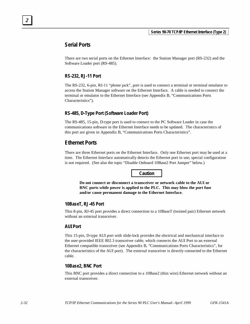
2-32 TCP/IP Ethernet Communications for the Series 90 PLC User's Manual – April 1999 GFK-1541A
2
Serial Ports
There are two serial ports on the Ethernet Interface: the Station Manager port (RS-232) and theSoftware Loader port (RS-485).
RS-232, RJ-11 Port
The RS-232, 6-pin, RJ-11 “phone jack”, port is used to connect a terminal or terminal emulator toaccess the Station Manager software on the Ethernet Interface. A cable is needed to connect theterminal or emulator to the Ethernet Interface (see Appendix B, “Communications PortsCharacteristics”).
RS-485, D-Type Port (Software Loader Port)
The RS-485, 15-pin, D-type port is used to connect to the PC Software Loader in case thecommunications software in the Ethernet Interface needs to be updated. The characteristics ofthis port are given in Appendix B, “Communications Ports Characteristics”.
Ethernet Ports
There are three Ethernet ports on the Ethernet Interface. Only one Ethernet port may be used at atime. The Ethernet Interface automatically detects the Ethernet port in use; special configurationis not required. (See also the topic “Disable Onboard 10Base2 Port Jumper” below.)
Caution
Do not connect or disconnect a transceiver or network cable to the AUI orBNC ports while power is applied to the PLC. This may blow the port fuseand/or cause permanent damage to the Ethernet Interface.
10BaseT, RJ-45 PortThis 8-pin, RJ-45 port provides a direct connection to a 10BaseT (twisted pair) Ethernet networkwithout an external transceiver.
AUI Port
This 15-pin, D-type AUI port with slide-lock provides the electrical and mechanical interface tothe user-provided IEEE 802.3 transceiver cable, which connects the AUI Port to an externalEthernet compatible transceiver (see Appendix B, “Communications Ports Characteristics”, forthe characteristics of the AUI port). The external transceiver is directly connected to the Ethernetcable.
10Base2, BNC PortThis BNC port provides a direct connection to a 10Base2 (thin wire) Ethernet network without anexternal transceiver.
Series 90-70 TCP/IP Ethernet Interface (Type 2)

GFK-1541A Chapter 2 Installing the Ethernet Interface 2-33
2
Default Station Address Label
The Default Station Address label lists the MAC address to be used by this Interface.
Disable Onboard 10Base2 Port Jumper
This jumper (“JP7”) must be in place to ensure proper network operation only when using anexternal AUI transceiver connected to the AUI port that is externally powered. This jumper isnormally not installed.
Replaceable +12VDC Fuse
A user-replaceable fuse (FU3) is provided on the +12VDC power that is supplied by the EthernetInterface to the AUI network port for use by an external transceiver. Replace only with a 5 x20mm, 250V, 1 A, fast-acting fuse.

2-34 TCP/IP Ethernet Communications for the Series 90 PLC User's Manual – April 1999 GFK-1541A
2
Procedure 1: Installing the Ethernet Interface in the PLC
This section describes the physical installation of the Ethernet Interface (Type 2) into the Series90-70 PLC rack. For information on the installation procedures for the rack, Series 90-70 CPU,power supply, and other Series 90-70 modules, refer to GFK-0262, Series 90-70 ProgrammableController Installation Manual.
Equipment Required to Perform the Installation Procedures
In addition to the Ethernet Interface (Type 2), make sure you have the items listed below beforeyou begin.
� Series 90-70 PLC rack.
� Series 90-70 power supply.
Note
The Ethernet Interface requires a power supply that can provide +12 Vdc whenusing an external transceiver on the AUI port. Under these conditions, use oneof the following Series 90-70 power supplies:
IC697PWR711 IC697PWR724 IC697PWR748
If the AUI port is not in use, +5 Vdc is all that is required. Under theseconditions, power supply IC697PWR710 is sufficient.
� A Series 90-70 CPU.
� PLC programming software: Logicmaster 90-70 version 6.02 or higher or Control version1.0 or higher (runs on a personal computer).
� Ethernet cables and, if using the AUI port, an Ethernet-compatible AUI transceiver. (SeeAppendix B, “Communications Ports Characteristics”, for more information.)
� A serial cable for the Station Manager port on the Ethernet Interface (see Appendix B).Optional
� A terminal or IBM-compatible personal computer equipped with terminal emulation software.Optional
� A Phillips-head screwdriver.
Note
If your installation requires CE Mark compliance, please refer to GFK-1179,Installation Requirements for Conformance to Standards, shipped with the PLCprogramming software, for additional guidelines.
Series 90-70 TCP/IP Ethernet Interface (Type 2)

GFK-1541A Chapter 2 Installing the Ethernet Interface 2-35
2
Ethernet Interface Installation
This section describes the physical mounting of the Ethernet Interface into the Series 90-70 PLCrack. For information on the installation procedures for the rack, Series 90-70 CPU, PowerSupply, and other Series 90-70 modules, refer to GFK-0262, Series 90-70 ProgrammableController Installation Manual.
Warning
Do not insert or remove modules with power applied. This could cause thePLC to Stop, damage the module, or result in personal injury.
1. Be sure the Series 90-70 PLC rack power is OFF.
2. Slide the Ethernet Interface into the desired slot—normally the first available slot to the rightof the CPU.
Press firmly to seat the Interface, but do not force the Interface. Tighten the screws on the topand bottom tabs.
Note
The Series 90-70 Ethernet Interface (Type 2) must be installed in the main rack;installation in an expansion rack is not supported. The Ethernet Interface willnot operate properly if there are empty slots to the left of the slot you select.
3. Connect one of the Ethernet ports on the Ethernet Interface to the network. If you are usingan external transceiver, connect the transceiver cable to the AUI port on the EthernetInterface. The other end of the transceiver cable should be connected to an external IEEE802.3 compatible transceiver which is attached to the Ethernet network. SQE must beenabled on the transceiver.
Caution
Do not connect or disconnect a transceiver or network cable to the AUI orBNC ports while power is applied to the PLC. This may blow the port fuseand/or cause permanent damage to the Ethernet Interface.
4. Set the CPU Run/Stop switch to STOP.
5. Continue with Procedure 2: Configuring the Ethernet Interface.
Series 90-70 TCP/IP Ethernet Interface (Type 2)

2-36 TCP/IP Ethernet Communications for the Series 90 PLC User's Manual – April 1999 GFK-1541A
2
Procedure 2: Configuring the Ethernet Interface
Before you can use the Ethernet Interface with the Series 90-70 PLC, you must configure theInterface using the PLC programming software. The PLC configuration software allows you tospecify the modules and I/O that will reside in your Series 90-70 PLC rack(s).
For the Ethernet Interface specifically, the configuration software allows you to:
� Define the Status address of the Ethernet Interface.
� Assign the IP address for the Ethernet Interface, and optionally the subnet mask, the gatewayaddress, and the name server address.
� Configure the serial ports (optional).
Configuring the Interface Using Logicmaster 90-70 Configuration Software
To configure the Ethernet Interface, access the I/O Configuration rack screen in the Logicmaster90-70 Configuration Package, and do the following:
1. Move the cursor to the desired rack and slot location. The slot may be either unconfigured orpreviously configured.
2. Press the Communications softkey, i.e., Comm (F6)
3. Press ethnet (F2).
4. Press “ ↓” (down arrow) to highlight “IC697CMM742”, then press Enter to select theEthernet Interface.
5. Configure the Ethernet parameters. Refer to the topic “Configuration Parameters” thatfollows for more information on these fields.
6. Optionally, after you have assigned the Ethernet parameters, press Page Down to display theserial port parameters. You can then change the default settings of the serial ports (optional).Refer to the topic “Configuration Parameters” that follows for more information on thesefields. We recommend leaving the serial port parameters at default settings.
7. After you have completed the configuration, press the Escape key to return to the rackdisplay. Press Escape again to save the configuration to disk.
8. Store the configuration to the PLC so these settings can take effect.
Refer to GFK-0263, Logicmaster 90-70 Programming Software User’s Manual for moreinformation on using Logicmaster 90-70 software.
Series 90-70 TCP/IP Ethernet Interface (Type 2)

GFK-1541A Chapter 2 Installing the Ethernet Interface 2-37
2
Configuring the Interface Using Windows-Based Programming SoftwareTo configure the Ethernet Interface using Control programming software, do the following:
1. From the Browser, double-click the 90-70 Rack System–Local Rack icon. The Local RackWindow will appear.
2. Click the tab corresponding to the desired rack.
3. Click the desired slot, press the right mouse button, and choose Add Module from the menu.(If the slot already contains a module, choose Replace Module.) The Module Catalog dialogbox will appear.
4. In the Module Catalog dialog box, click the Communications tab, select IC697CMM742Ethernet Controller Type 2, then click the OK button. The Parameters dialog box then willappear.
5. This dialog box will allow you to edit the module’s Ethernet parameters. To edit a parametervalue, click in the appropriate Values field.
6. Optionally, after you have completed the Settings tab, you can configure parameters for theStation Manager and Software Load ports by clicking the appropriate tab. The defaultsettings for the serial ports can then be changed (optional). Refer to the topic “ConfigurationParameters” that follows for information on these fields. We recommend leaving the serialport parameters at default settings.
7. If you want to view the power consumption of this module, click the Power Consumption tab.After you have configured all of the module’s applicable parameters, click the OK button.The module will now appear in the selected slot.
8. Store the configuration to the PLC so these settings can take effect.
For more information, refer to Online Help in the PLC programming software.
Configuration Parameters
Ethernet ParametersConfiguration Mode: This is fixed as TCP/IP.
Adapter Name: A symbolic name representation of the associated IP Address. The character setis listed in Chapter 5, “Network Administration Support”. The Adapter Name is associated withthe IP address used in Ethernet Global Data. If supported in the PLC programming software,view all adapter names in Hardware Configuration by going to the Edit menu, choosing RackOperations, and selecting Name Resolution. Adapter names are listed in the Adapter Names tab.
IP Address, Subnet Mask, Gateway IP Address, and Name Server IP Address: These valuesshould be assigned by the person in charge of your network (the network administrator). TCP/IPnetwork administrators are familiar with these parameters. It is important that these parametersare correct, otherwise the Ethernet Interface may be unable to communicate on the network and/ornetwork operation may be corrupted. It is especially important that each node on the network isassigned a unique IP address.
Series 90-70 TCP/IP Ethernet Interface (Type 2)
2-38 TCP/IP Ethernet Communications for the Series 90 PLC User's Manual – April 1999 GFK-1541A
2
However, if you have no network administrator and are using a simple isolated network with nogateways, you can use the following range of values for the assignment of local IP addresses:
10.0.0.1 First PLC10.0.0.2 Second PLC10.0.0.3 Third PLC. .. .. .10.0.0.255 PLC Programmer TCP or host
Also, in this case, set the subnet mask, gateway IP address, and name server IP address to 0.0.0.0.
Note
If the isolated network is ever connected to another network, the IP addresses10.0.0.1 through 10.0.0.255 must not be used and the subnet mask, gatewayIP address, and name server address must be assigned by the networkadministrator. The IP addresses must be assigned so that they are compatiblewith the connected network. Refer to Chapter 5, “Network AdministrationSupport”, for more information on addressing.
See also the section “Determining If an IP Address Has Already Been Used” inProcedure 4.
Status Address: The Status Reference Type is the location of the LAN Interface Status (LIS) bits(16 bits) and the Channel Status bits (64 bits). The Channel Status bits are always locatedimmediately following the LAN Interface Status bits. The Status address can be assigned to %I,%Q, %R, %AI, or %AQ memory. The default value is the next available %I address.
Note
Do not use the 80 bits assigned to the LIS bits and Channel Status bits for otherpurposes or your data will be overwritten.
Status Length: This is the sum of the LIS bits and the Channel Status bits. This value isautomatically set to either 80 bits (for %I and %Q Status address locations) or 5 words (for %R,%AI, and %AQ Status address locations).
Network Routing Pair #1, #2, #3: These parameters are used to define an IP routing partnershipwith another network adapter within the same PLC system. Network routing pairs is an advancedfeature that should be set only by individuals who have detailed knowledge of PLCcommunications.
Network Time Sync: Selection of the method used to synchronize the real-time clocks over thenetwork. Currently the choices are None (for no network time synchronization) and SNTP (forsynchronization to remote SNTP servers on the network).
Series 90-70 TCP/IP Ethernet Interface (Type 2)

GFK-1541A Chapter 2 Installing the Ethernet Interface 2-39
2
Serial Port Parameters
Data Rate (bps): Data rate (bits per second) for the port. Choices are 300, 600, 1200, 2400,4800, 9600‡, or 19200*.
Parity: Type of parity to be used for the port. Choices are None‡, Even, or Odd*.
Stop Bits: Enter the number of stop bits. Choices are 1*‡ or 2.
Flow Control: This parameter is currently not used by the Ethernet Interface. Changing thisparameter has no effect.
Turnaround Delay: Turnaround delay time (in milliseconds) to be used for the port. Choices areNone*‡, 10 ms, 100 ms, or 500 ms.
Timeout: This parameter is currently not used by the Ethernet Interface. Changing thisparameter has no effect.
* Default selection for the Software Loader Port.‡ Default selection for the Station Manager Port.
Series 90-70 TCP/IP Ethernet Interface (Type 2)

2-40 TCP/IP Ethernet Communications for the Series 90 PLC User's Manual – April 1999 GFK-1541A
2
Procedure 3: Verifying Proper Power-Up of the Ethernet Interface
Powering-up the Ethernet Interface
After configuring the Interface as explained in Procedure 2, follow the procedure below to verifythat the Ethernet Interface is operating correctly.
1. Turn power OFF to the PLC for 3–5 seconds, then turn the power back ON. This willinitiate a series of diagnostic tests.
The MODULE OK LED will blink indicating the progress of power-up.
2. The LEDs will have the following pattern upon successful power-up. At this time theEthernet Interface is fully operational and on-line.
LED Ethernet Interface OnlineMODULE OK ● (ON)
LAN ONLINE ●/✲ (ON/Traffic)
SERIAL ACTIVE ❍ (OFF)
STATUS ● (ON)
If the STATUS LED is OFF, check the PLC Fault Table.Alternatively, use the Station Manager LOG command as explainedin GFK-1186, TCP/IP Ethernet Communications for the Series 90PLC Station Manager Manual.
Problems During Power-up
If a problem is detected during power-up, the Ethernet Interface may not transition directly to theOperational state. If the Interface does not transition to Operational, check the LED pattern onthe Interface and refer to Figure 2-6 to find out where the Interface stopped. Refer to Table 2-3for corrective actions.
Series 90-70 TCP/IP Ethernet Interface (Type 2)

GFK-1541A Chapter 2 Installing the Ethernet Interface 2-41
2
States of the Series 90-70 TCP/IP Ethernet Interface (Type 2)
Figure 2-6. States of the Series 90-70 TCP/IP Ethernet Interface (Type 2)
Series 90-70 TCP/IP Ethernet Interface (Type 2)
Ethernet Interface
Initializing
(approx.10-20 seconds)
��
�
�
The Ethernet Interface is initialized by- Powering-up the PLC- Storing a new configuration to the PLC with changes for the Ethernet Interface- Pressing the Restart pushbutton- Issuing a Station Manager RESTART, LOAD, or MAINT command- Internal System Error occurring when Interface is Operational
DiagnosticsPass?
LoadRequest orSoftwareCorrupted?
Waiting forConfiguration from
(max. 2 minutes)PLC CPU
��
�
�
IP address =
0.0.0.0
MaintenanceRequest or
Fatal SystemError?
Operational
Software Load Caused by- Restart pushbutton pushed until bottom LED turns ON- Station Manager LOAD command issued- Detection of corrupt software
Waiting for IP Address Caused by- Not configuring Interface using configuration software- Configuring Interface with IP address = 0.0.0.0- New CPU with no configuration- CPU failure to communicate with Interface
Continue to Maintenance or Operational Caused by- IP address received from network BOOTP server- IP address entered by BOOTP Station Manager command
Maintenance Request Caused by- Restart pushbutton pushed until bottom two LEDs turn ON- Station Manager MAINT command issued- Fatal System Error while in Operational State forced a restart
The LEDs are labeled from top to bottom as follows:MODULE OKLAN ONLINESERIAL ACTIVESTATUS
The symbols used for the LEDs are defined as follows:
� = OFF
z = ON
� = Slow Blink; multiple slow blining LEDs blink in unison
� = Fast Blink
∗ = Traffic (blinks when there is traffic on the line)
The process symbols are defined as follows:
= Temporary condition; requires no intervention
= Decision point during power-up
= Interface State; normally the Interface remains in a State unless there is user intervention
Symbols
z
z/ ∗/��
z/�
F
C
Hardware
A�
�
�
�
Failure
Software
B
Load
����
Waiting for
D�
�
IP Addressz/ ∗/�
Maintenancez/ ∗/�
z/�
�
E
No
No
No
No
Yes
Yes
Yes
Yes
Done
IP Address Received
Maintenance- Client and server capability disabled- Uses default Advanced Parameters- Permits changes to Advanced Parameters
Operational- Full support for client and server capability- Uses user defined Advanced Parameters
�
�
�
1
1
22
3
3
4
4
5
5

2-42 TCP/IP Ethernet Communications for the Series 90 PLC User's Manual – April 1999 GFK-1541A
2
Table 2-3. Problems During Power-Up
LED Pattern Where Stopped Possible Cause Corrective Actions
❍ MODULE OK OFF)
❍ LAN ONLINE (OFF)
❍ SERIAL ACTIVE (OFF)
❍ STATUS (OFF)
A
HardwareFailure
Fatal Hardware Error. � Make sure the PLC has power.� Examine PLC Fault Table for clues.*� Recheck PLC Programmer configuration.� Power off the PLC rack, inspect the Interface
for loose components, reseat the Interface,and Restart.
� Try a different slot.� If the problem persists, replace the Interface
or PLC hardware.
✫ MODULE OK (Slowblink)
✫ LAN ONLINE (Slowblink)
✫ SERIAL ACT. (Slowblink)
✫ STATUS (Slowblink)
All LEDs blink in unison.
B
SoftwareLoader
� Restart pushbutton until thebottom LED turns ON.
� Station Manager LOADcommand issued.
� Software corrupt.
� Connect a PC Software Loader and loadnew software. See Appendix C.
� Cycle power or press Restart pushbuttonagain for less than 5 seconds to restart theInterface and clear the load request.
✫ MODULE OK (Slowblink)
❍ LAN ONLINE(OFF)
❍ SERIAL ACT. (OFF)
❍ Status (OFF)
C
Waiting forConfigurationfrom PLC
� Did not configure slot usingPLC Programmer.
� New CPU with noconfiguration.
� CPU not communicatingwith Ethernet Interface
(Condition can last amaximum of 2 minutes.)
� Use configuration software to configure theInterface then store the configuration to thePLC CPU.
� Make sure Interface is in the correct slot onthe in the PLC rack.
� Power cycle the PLC.� Clear faults and Restart Interface.
✫ MODULE OK (Slowblink)
●/✲/❍ LAN ONL.(ON/Traffic/OFF)
❍ SER. ACT (OFF/Slowblink)
✫ STAT US (Slowblink)
MODULE OK and STATUS blink inunison.
D
Waiting for IPAddress
Interface’s IP address has notbeen configured or has beenconfigured as 0.0.0.0.
� Use PLC Programmer configuration softwareto configure the Interface with a non-zero IPaddress.
� Use a BOOTP server to provide Interfacewith a non-zero IP Address.
✫ MODULE OK (Slowblink)
●/✲/❍ LAN ONL. (ON/Traffic/OFF)
✫ SERIAL ACT. (Slowblink)
●/❍ STATUS (ON/OFF)
MODULE OK and SERIAL ACTIVEblink in unison.
E
Maintenance
� Restart pushbutton untilbottom two LEDs turn ON.
� Station Manager MAINTcommand issued.
� Internal System Error whenInterface was Operationalcaused a restart andentrance into Maintenance.
� If you did not intend to enter Maintenance,press the Restart pushbutton for less than 5seconds. This clears the Maintenancerequest.
� Examine PLC Fault Table for clues.*� If you need to use the Station Manager to
troubleshoot a problem, see GFK-1186,TCP/IP Ethernet Communications for theSeries 90 PLC Station Manager Manual.
● MODULE OK (ON)
●/✲/❍ LAN ONL. (ON/Traffic/OFF)
❍ SERIAL ACTIVE (OFF)
●/❍ STATUS (ON/OFF)
F
Operational
If the LAN ONLINE LED isOFF, the problem may be:
� Network cable notconnected or transceiver notconnected to Interface orbad transceiver.
� Network cable notterminated properly.
� SQE not enabled ontransceiver.
If the STATUS LED is OFF,an exception condition hasoccurred.
� Connect cable and transceiver properly.Replace transceiver.
� Terminate network cable properly.� Set SQE ON on transceiver in accord with
manufacturer’s instructions.
� Examine PLC Fault Table to find out whythe STATUS LED is OFF. *
* Identify the PLC fault message using the PLC Programmer then refer to Table 6-1 in Chapter 6, “Troubleshooting”, forcorrective actions.
Series 90-70 TCP/IP Ethernet Interface (Type 2)

GFK-1541A Chapter 2 Installing the Ethernet Interface 2-43
2
Procedure 4: Pinging TCP/IP Ethernet Interfaces on the Network
PING (Packet InterNet Grouper) is the name of a program used on TCP/IP networks to testreachability of destinations by sending them an ICMP echo request message and waiting for areply. Most nodes on TCP/IP networks, including the Series 90-70 Ethernet Interface (Type 2),implement a PING command.
The user should ping each installed Ethernet Interface. When the Ethernet Interface responds tothe ping, it verifies that the interface is operational and configured properly. Specifically itverifies that acceptable TCP/IP configuration information has been stored to the Interface.
Pinging the Interface from a UNIX® Host or a PC Running TCP/IP Software
A ping command can be executed from a UNIX host or PC running TCP/IP (since most TCP/IPcommunications software provides a ping command) or from another Ethernet Interface.* Whenusing a PC or UNIX host, the user can refer to the documentation for the ping command, but ingeneral, all that is required is the IP address of the remote host as a parameter to the pingcommand. For example, at the command prompt type:
ping 10.0.0.1
Determining If an IP Address Has Already Been Used
It is very important not to duplicate IP addresses. To determine if you have configured yourEthernet Interface with the same IP address as another node:
1. Disconnect your Interface from the LAN.
2. Ping the disconnected Interface’s IP address. If you get an answer to the ping, then thechosen IP address is already in use by another node. You must correct this situation byassigning unique IP addresses.
* To use another GE Fanuc Ethernet Interface, refer to the PING command in GFK-1186,TCP/IP Ethernet Communications for the Series 90 PLC Station Manager Manual.
® UNIX is a registered trademark exclusively licensed through X/Open Company LTD.
Series 90-70 TCP/IP Ethernet Interface (Type 2)
GFK-1541A 3-1
Programming Communications Requests
This chapter describes how to program PLC to PLC communications over the Ethernet network.Details of the COMMREQ function and the Channel commands are presented here. The chapteris divided into 5 sections:
n Section 1: The Communications Request
n Section 2: The COMMREQ Function Block and Command Block
n Section 3: Channel Commands
n Section 4: Status Data
n Section 5: Controlling Communications in the Ladder Program
Note
This chapter applies only to PLCs being used as client PLCs to initiate TCP/IPcommunications. No programming is required for server operations.
3Chapter

3-2 TCP/IP Ethernet Communications for the Series 90 PLC User's Manual – April 1999 GFK-1541A
3
Section 1: The Communications Request
“Communications Request” is a term used to describe all the user elements required for correctlyinitiating Channel commands from a Series 90 PLC. This section describes the elements of theCommunications Request.
No programming of Communications Requests is required for PLCs acting as servers which aremerely targets of other systems’ requests but do not themselves initiate requests.
Structure of the Communications Request
The Communications Request is made up of the following elements:
n The COMMREQ Function Block (ladder instruction)
n The COMMREQ Command Block
n The Channel Command
n Status Data (COMMREQ Status word, LAN Interface Status and Channel Status bits)
n The logic program controlling execution of the COMMREQ Function Block
The figure below illustrates the relationship of these elements:
Figure 3-1. Elements of the Communications Request
a44916c
INPUTSAND
OUTPUTSFOR COMMREQ
FUNCTION
COMMANDBLOCK
ADDRESS
COMMREQFUNCTION BLOCK
DETAILSOF THE
CHANNELCOMMAND
COMMREQCOMMAND BLOCK
COMMREQSTATUS WORD
STATUSCODES
COMMREQSTATUSWORD
ADDRESS
STATUS BITS
LAN INTERFACE STATUSAND CHANNEL STATUS
BITS
INITIATESCOMMREQFUNCTION
BLOCK
CONTROLLOGIC
Location in PLC memoryspecified when configuring
the Interface usingConfiguration Software

GFK-1541A Chapter 3 Programming Communications Requests 3-3
3
COMMREQ Function Block
The COMMREQ Function Block is the ladder instruction that triggers the execution of theChannel command. In the COMMREQ Function Block, you specify the rack and slot location ofthe Ethernet Interface, a task value, and the address of a location in memory that contains theCommand Block. There is also a fault output on the COMMREQ Function Block that indicatescertain programming errors. See Section 2 for details.
COMMREQ Command Block
The COMMREQ Command Block is a structure that contains information about the Channelcommand to be executed. The Command Block consists of two parts:
Common Area - includes the address of the COMMREQ Status word (CRS word).
Data Block Area - describes the Channel command to be executed.
When the COMMREQ function is initiated, the Command Block is transferred to the EthernetInterface for action.
See Section 2 for a description of the Common Area of the Command Block and Section 3 fordetails on the Data Block area and Channel commands.
Channel Commands
The Channel commands are a set of client PLC commands used to communicate with a serverPLC.
Advantages of Channel Commands
The advantage of Channel commands is their ability to establish a channel to execute multipleperiodic reads or writes with a single initiation of a COMMREQ function. A Channel commandcan also be used to execute a single read or write.
Up to 32 channels (numbered 1–32) can be established by a Series 90-70 Ethernet Interface. Upto 16 channels (numbered 1–16) can be established by a Series 90-30 Ethernet Interface. Thechannel number is specified in the Command Block for the Channel command. The channel canbe monitored using the Channel Status bits and the Detailed Channel Status words.
See Section 3 for more information.
3-4 TCP/IP Ethernet Communications for the Series 90 PLC User's Manual – April 1999 GFK-1541A
3
Status Data
There are several types of status available to the client PLC logic program.
LAN Interface Status Bits (LIS Bits): The LIS bits comprise bits 1–16 of the 80-bit status area. Thelocation of this 80-bit status area is assigned using the Configuration software in the “StatusAddress” field. The LIS bits contain information on the status of the Local Area Network (LAN)and the Ethernet Interface itself. See Section 4 for more information.
Channel Status Bits: The Channel Status bits comprise bits 17–80 (64 bits) of the 80-bit statusarea. These bits consist of an error bit and a data transfer bit for each of the channels that can beestablished (32 channels for the Series 90-70 Ethernet Interface, 16 channels for the Series 90-30Ethernet Interfaces). Status bits for unused channels are always set to zero. See Section 4 for moreinformation.
COMMREQ Status Word (CRS Word): The 16-bit CRS word will receive the initial status of thecommunication request. The location of the CRS word is assigned for each COMMREQ functionin the COMMREQ Command Block. See Section 4 for more information.
Detailed Channel Status Words (DCS Words): This detailed status data is retrieved for aparticular channel using the Retrieve Detailed Channel Status Command. See Section 3 forinformation on the command and Section 4 for the contents and format of the retrieved channelstatus.
FT Output of the COMMREQ Function Block: This output indicates that the PLC CPU detectederrors in the COMMREQ Function Block and/or Command Block and did not pass the CommandBlock to the Ethernet Interface. See Section 4 for details.
The Logic Program Controlling Execution of the COMMREQ Function Block
Care must be taken in developing the logic that controls the execution of the COMMREQ function.The COMMREQ function must be initiated by a one-shot to prevent the COMMREQ from beingexecuted repeatedly each CPU scan, as this will overrun the capability of the Ethernet Interface andpossibly require a manual restart. Checking certain status bits before initiating a COMMREQfunction is also important. In particular, the LAN Interface OK bit should be used as an interlock toprevent execution of the COMMREQ function when the Ethernet Interface is not operational.Following initiation of a COMMREQ on a channel, no further COMMREQs should be issued tothat channel until a non-zero CRS word has been returned to the program from the EthernetInterface.
See Section 5 for tips on developing your program.

GFK-1541A Chapter 3 Programming Communications Requests 3-5
3
Operation of the Communications Request
The figure and text below explains how a Communications Request is executed. The figurespecifically illustrates the successful operation of an Establish Read Channel command.
ClientSeries 90-70
PLC CPU BackplaneEthernetInterface
ServerEthernet InterfaceLAN
Power flows to COMMREQin ladder program
Command Block sent toInterface Verify
Command Blockand set up channelto server PLC
Read Request
Data
Data
Read Request
DataData
Client
Data
Data
COMMREQStatus Word
Return COMMREQStatus (CRS) Wordto CPU
.
.
.
.
.
.Read Request
DataData
Data
Pulse Data Transfer bitData Transfer
Pulse Data Transfer bit
Pulse Data Transfer bit
Data
Domain of a channelDomain of a TCP connection
pulse received
Data Transferpulse received
Data Transferpulse received
Domain of a remote server
ServerCPUBackplane
Read RequestData
Read RequestData
Read RequestData
PLC PLC
Figure 3-2. Operation of the Communications Request for an Establish Read Channel Command
1. A Communications Request begins when there is power flow to a COMMREQ function in theclient PLC. At this time, the Command Block data is sent from the PLC CPU to the EthernetInterface.
2. For the Establish Read Channel command, the COMMREQ Status word (CRS word) isreturned immediately if the Command Block is invalid. If the syntax is correct, then the CRSword is returned after the first significant event: upon failure to establish a channel correctlyand in a timely manner or upon the first successful transfer of data.
Once the channel is successfully set up to the server PLC, the Ethernet Interface performs theperiodic reads as specified in the Command Block.

3-6 TCP/IP Ethernet Communications for the Series 90 PLC User's Manual – April 1999 GFK-1541A
3
Section 2: COMMREQ Function Block and Command Block
This section describes the programming structures common to all Communications Requests: theCOMMREQ Function Block and the Command Block.
The COMMREQ Function Block
The Communications Request is triggered when the logic program passes power to theCOMMREQ Function Block.
(Enable ) - - - - - - - - - - - - -
(Command Block address)
(Rack/Slot Location ofthe Ethernet Interface)
(Task value)
-
-
-
- Function Faulted (logic)
- OK (Series 90-70 PLCs only)COMMREQ
IN FT
SYSID
TASK
Each of the inputs and outputs are discussed in detail below. It is important to understand that theCommand Block address points to the location in memory you have setup as the Command Block.
Enable: Control logic for activating the COMMREQ Function Block. See Section 5 for tips ondeveloping your program.
IN: The location of the Command Block. It can be any valid address within a word-oriented areaof memory (%R, %AI, or %AQ for the Series 90-30 Ethernet Interface and the Series 90-30CPU364) (%R, %AI, %AQ, %P, or %L for the Series 90-70 Ethernet Interface (Type 2)).
SYSID: A hexadecimal word value that gives the rack (high byte) and slot (low byte) location ofthe Ethernet Interface. For the Series 90-30 CPU364, this must always be set to 0001 to specifyrack 0, slot 1.
Examples:
Rack Slot Hex Word Value
0 4 0004H
3 4 0304H
2 9 0209H
4 2 0402H
Note
The Series 90-70 Ethernet Interface (Type 2) is supported only in the main PLCrack (rack number 0).

GFK-1541A Chapter 3 Programming Communications Requests 3-7
3
TASK: For the Series 90-30 CPU364, this must always be set to 21 decimal (0015H). For theSeries 90-30 Ethernet Interface and the Series 90-70 Ethernet Interface (Type2), this must alwaysbe set to zero.
Caution
Entering an incorrect TASK value may cause the Ethernet Interface to fail.
OK Output: (Series 90-70 PLC only) The OK output is set if the PLC CPU has successfullydelivered the COMMREQ to the Ethernet Interface.
FT Output: The FT output is set if the PLC CPU (rather than the Ethernet Interface) detects thatthe COMMREQ fails. In this case, the other status indicators are not updated for thisCOMMREQ. See Section 3 for more information.
The COMMREQ Command Block
When the COMMREQ function is initiated, the Command Block is sent from the PLC CPU to theEthernet Interface. The Command Block contains the details of a Channel command to beperformed by the Interface.
The address in CPU memory of the Command Block is specified by the IN input of theCOMMREQ Function Block. This address can be any valid address within a word-oriented areaof memory (%R, %AI, or %AQ for the Series 90-30 Ethernet Interface and the Series 90-30CPU364) (%R, %AI, %AQ, %P, or %L for the Series 90-70 Ethernet Interface (Type 2)). TheCommand Block is set up using an appropriate programming instruction (the BLOCK MOVE orDATA_INIT (Series 90-70 PLC only) Function Blocks are recommended).
The Command Block has the following structure:
Word 1 Data Block Length (words)
Word 2 WAIT/NOWAIT Flag
Word 3 CRS Word Memory Type
Word 4 CRS Word Address Offset
Word 5 Reserved
Word 6 Reserved
Words 7 and up Data Block (Channel Command Details)
When entering information for the Command Block, refer to these definitions:
(Word 1) Data Block Length: This is the length in words of the Data Block portion of theCommand Block. The Data Block portion starts at Word 7 of the Command Block. The length ismeasured from the beginning of the Data Block at Word 7, not from the beginning of theCommand Block. The correct value for each command, and the associated length of eachcommand, is specified in Section 3.
(Word 2) WAIT/NOWAIT Flag: This flag must be set to zero for TCP/IP EthernetCommunications.

3-8 TCP/IP Ethernet Communications for the Series 90 PLC User's Manual – April 1999 GFK-1541A
3
COMMREQ Status Word: The Ethernet Interface updates the CRS word to show success orfailure of the command. Command words 3 and 4 specify the PLC memory location of the CRSword.
(Word 3) COMMREQ Status Word Memory Type: This word specifies the memory type for theCRS word. The memory types are listed in the table below:
Type Value(Decimal)
Value(Hex.)
Description
%R 8 08H Register memory (word mode)%AI 10 0AH Analog input memory (word mode)%AQ 12 0CH Analog output memory (word mode)
%I 1670
10H46H
Discrete input memory (byte mode)Discrete input memory (bit mode)
%Q 1872
12H48H
Discrete output memory (byte mode)Discrete output memory (bit mode)
%T 2074
14H4AH
Discrete temporary memory (byte mode)Discrete temporary memory (bit mode)
%M 2276
16H4CH
Discrete momentary internal memory (byte mode)Discrete momentary internal memory (bit mode)
%G 5686
38H56H
Discrete global data table (byte mode)Discrete global data table (bit mode)
(Word 4) COMMREQ Status Word Address Offset: This word contains the offset within thememory type selected. The status word address offset is a zero-based number. For example, ifyou want %R1 as the location of the CRS word, you must specify a zero for the offset. The offsetfor %R100 would be 99 decimal. Note, however, that this is the only zero-based field in theChannel commands.
For information on the contents of the COMMREQ Status word, see Section 4.
(Word 5): Reserved. Set to zero.
(Word 6): Reserved. Set to zero.
(Words 7 and up) Data Block: The Data Block defines the Channel command to be performed.For information on how to fill in the Channel command information, see Section 3.

GFK-1541A Chapter 3 Programming Communications Requests 3-9
3
Section 3: Channel Commands
This section describes the Channel commands. A detailed description and example of eachChannel command is included. There are five Channel commands as follows.
1. Establish Read Channel
2. Establish Write Channel
3. Send Information Report
4. Abort Channel
5. Retrieve Detailed Channel Status
Establishing a Channel
The Ethernet Interface transfers data to or from another PLC using a channel. There are twochannel commands for transferring data between PLCs:
n Establish Read Channel
n Establish Write Channel
The Ethernet Interface also transfers data to a host, another computer on the network, which isrunning Host Communications Toolkit (HCT) software. There is one channel command fortransferring data to a host computer:
n Send Information Report
These Channel commands are based on the concept of periodic data transfers. The client (local)PLC uses a single COMMREQ function to establish a channel (connection) to a server (remote)PLC and to request that specific data be periodically transferred between the PLCs.
Note
To simplify the discussion of the Command Blocks, we make the assumptionthat the operator/programmer is local to the client PLC and the server is remotefrom this operator/programmer.
The Ethernet Interface automatically manages the establishment of communications and theperiodic data transfer. Parameters in the Command Block specify the frequency and direction ofthe transfer, and the memory locations in the client and server to be used in the transfer.
Aborting and Re-tasking a Channel
There are four ways a channel can be aborted:
1. When the PLC CPU is stopped, all channels in use are aborted automatically.
2. A channel (or all channels) can be aborted by issuing an Abort Channel command.
3. A channel in use can be re-tasked by issuing an establish command for its channel number.This aborts the previous channel operation and then performs the new channel operation.
4. A channel is also automatically aborted if a fatal error occurs.

3-10 TCP/IP Ethernet Communications for the Series 90 PLC User's Manual – April 1999 GFK-1541A
3
Retrieving Detailed Status on the Channel
As discussed before, there are several forms of status available to the ladder program. These areall discussed in Section 4. One form of status is obtained through the Retrieve Detailed ChannelStatus (RDCS) command described later in this section.
Specifying a Network Address
All establish commands must identify the remote server device with which data will betransferred. The remote device may be specified in two ways: By IP address, or by a namepreviously defined with the proper IP address. Examples of each Network Address type areprovided for all establish commands. (For further information on the use of Network Addressnames, see Chapter 5, “Network Administration Support”.)

GFK-1541A Chapter 3 Programming Communications Requests 3-11
3
Establish Read Channel (2003)
The Establish Read Channel command requests that a channel be associated with a remote PLCand that data from the remote PLC be transferred (periodically) to the local PLC. The CommandBlock specifies the period, the number of reads from the server (remote PLC) to perform, and thetimeout allowed in waiting for each transfer to complete. The first read is performed immediately,regardless of the period specified.
Example 1 Command Block–Basic Example
Establish a channel (Channel 5) to a remote PLC at IP address 10.0.0.1. Return the COMMREQStatus word to %R10. Read remote PLC registers %R50–%R57 to local PLC registers %R100–%R107. Repeat the read 10 times, once every 7 seconds, with a timeout of 500 ms for each read.
Dec (Hex)Word 1 00017 (0011) Length of Channel command Data Block (17–25 words)Word 2 00000 (0000) Always 0 (no-wait mode request)Word 3 00008 (0008) Memory type of CRS word (%R)Word 4 00009 (0009) CRS word address minus 1 (%R10)*Word 5 00000 (0000) ReservedWord 6 00000 (0000) ReservedWord 7 02003 (07D3) Establish Read Channel command number
Word 8 00005 (0005) Channel number (5)Word 9 00010 (000A) Number of read repetitions (read 10 times)Word 10 00003 (0003) Time unit for read period (3=seconds)Word 11 00007 (0007) Number of time units for read period (every 7 seconds)Word 12 00050 (0032) Timeout for each read (500 ms)Word 13 00008 (0008) Local PLC - Memory type at which to store data (%R)Word 14 00100 (0064) Local PLC - Starting address at which to store data (%R100)
Word 15 00008 (0008) Remote PLC - Memory type from which to read data (%R)Word 16 00050 (0032) Remote PLC - Starting address from which to read data (%R50)Word 17 00008 (0008) Remote PLC - Number of memory units (8 registers)Word 18 00001 (0001) Remote PLC - Network Address type (IP Address)Word 19 00004 (0004) Remote PLC - Network Address length in words (4)Word 20 00010 (000A) Remote PLC - Register 1 of IP address (10)Word 21 00000 (0000) Remote PLC - Register 2 of IP address (0)
Word 22 00000 (0000) Remote PLC - Register 3 of IP address (0)Word 23 00001 (0001) Remote PLC - Register 4 of IP address (1)
Word 24–27 Remote PLC - Program Name (needed for access to remote %P or%L) (zero-terminated and padded)
Word 28–31 Remote PLC - Program Block (needed for access to remote %L)(zero-terminated and padded)
* Word 4 (CRS word address) is the only zero-based address in the Command Block. Only thisvalue requires subtracting 1 from the intended address.
The term local PLC isused here to identify theclient PLC—the PLCthat initiates thecommunicationsrequest.
The term remote PLCis used here to identifythe server PLC—thePLC that responds tothe communicationsrequest.

3-12 TCP/IP Ethernet Communications for the Series 90 PLC User's Manual – April 1999 GFK-1541A
3
(Word 7) Channel Command Number: Word 7 requests that a read channel be set up. If thecommand is processed successfully, it will result in attempting the specified number of transfersfrom the server to the client.
(Word 8) Channel Number: Word 8 specifies the channel to be used for the read. This value mustbe in the range of 1–32 for the Series 90-70 Ethernet Interface (Type 2) and 1–16 for the Series 90-30 Ethernet Interfaces. If the channel number is out of range, a command error indication will beplaced in the COMMREQ Status word. If the channel number is the same as a channel already inuse, the channel will be retasked to perform this new command.
(Word 9) Number of Read Repetitions: Word 9 specifies the number of reads to be performedbefore automatically completing the communications request and closing the channel. If this valueis set to 1, only a single read will be issued. If this value is set to 0, reads will be issuedcontinuously on the requested period until the channel is aborted.
(Word 10) Time Unit for Read Period: Words 10–11 together define how often the read is to beperformed (read period). Word 10 specifies the time unit such as seconds or minutes for the readperiod. Word 11 specifies the number of those units. The choices for the time units are specifiedin Table 3-1.
Table 3-1. Time Unit Values for Read/Write Repetition Period
Value Meaning1 hundredths of seconds (10 ms)
2 tenths of seconds (100 ms)
3 seconds
4 minutes
5 hours
Note: If Time Unit Value is 5 (hours), then the maximumusable value of Number of Time Units is 5965.
(Word 11) Number of Time Units for Read Period: Word 11 specifies the number of time unitsfor the read period. The read period is in effect even when the Channel command is setup to issuea single read.
Example Read Period Calculation: If Word 10 contains a value of 3 specifying seconds as thetime unit and Word 11 contains a value of 20, then the read period is 20 seconds.
A read will normally be issued at the start of each read period. If the pending read transfer hasnot completed during the read period, the Channel Error bit and Detailed Channel Status wordswill be set to indicate a non-fatal period error. The pending transfer can still complete after theperiod error occurs. For Channel commands set up to issue multiple reads, the next read transferwill be issued only after the pending read transfer completes.
If the Number of Time Units is zero, a subsequent transfer will be issued as soon as the previoustransfer completes. In this case, no period errors can occur.
(Word 12) Timeout for Each Read: Word 12 specifies the time (in hundredths of a second) theEthernet Interface will wait for a read transfer to complete before setting the Channel Error bitand Detailed Channel Status words to indicate a non-fatal timeout error. The transfer can stillcomplete even after a timeout occurs. As a result, an application can choose what to do if oneoccurs. If the timeout value is specified as zero, no timeout errors will be reported.
A Channel commandset up to issue a singleread can have only onepending read transfer.

GFK-1541A Chapter 3 Programming Communications Requests 3-13
3
For most applications a timeout need not be specified because the read period, in effect, acts as atimeout. (Word 12 should be zero for no timeout). However, there are two special circumstancesin which specifying a timeout is recommended:
n When the number of time units (Word 11) is zero, so that a subsequent transfer will be issuedas soon as the previous transfer completes and no period errors are reported. In this case atimeout value can be specified so that timeout errors will be reported by the Channel Error bit.
n When the read period is very long (minutes or hours). In this case a shorter timeout valuecan be specified so the application doesn’t have to wait for the read period to expire beforetaking action.
(Word 13) Local PLC - Memory Type: Words 13–14 specify the location in the local PLC wherethe Ethernet Interface will store data received from the remote PLC. Valid values for Word 13 arelisted in Table 3-2. The amount of data to be transferred is specified by the number of memoryunits of the data read from the remote PLC (Word 17).
Table 3-2. Series 90 PLC Memory Types
TypeValue
(Decimal) Description%L* 0 Program Block Local register memory (word mode)%P* 4 Program register memory (word mode)%R 8 Register memory (word mode)
%AI 10 Analog input memory (word mode)
%AQ 12 Analog output memory (word mode)
%I 1670
Discrete input memory (byte mode)Discrete input memory (bit mode)
%Q 1872
Discrete output memory (byte mode)Discrete output memory (bit mode)
%T 2074
Discrete temporary memory (byte mode)Discrete temporary memory (bit mode)
%M 2276
Discrete momentary internal memory (byte mode)Discrete momentary internal memory (bit mode)
%SA 2478
Discrete system memory group A (byte mode)Discrete system memory group A (bit mode)
%SB 2680
Discrete system memory group B (byte mode)Discrete system memory group B (bit mode)
%SC 2882
Discrete system memory group C (byte mode)Discrete system memory group C (bit mode)
%S † 3084
Discrete system memory (byte mode)Discrete system memory (bit mode)
%G 5686
Discrete global data table (byte mode)Discrete global data table (bit mode)
† Read-only memory, cannot be written to.* Can only be accessed in the Remote PLC (%L and %P are available in Series 90-70 PLCs only).
(Word 14) Local PLC - Memory Starting Address: Word 14 determines the starting address in thelocal PLC in which the data from the remote PLC is to be stored. The value entered is the offset (1-based) from the beginning of PLC memory for the memory type and mode specified in Word 13. Thisoffset will be either in bits, bytes, or words depending on the mode specified (for example, if Word13=16 and Word 14=2, then the starting address will be %I9). Valid ranges of values depend on thePLC’s memory ranges. The user is responsible for assuring that this area is large enough to containthe requested data without overwriting other application data.

3-14 TCP/IP Ethernet Communications for the Series 90 PLC User's Manual – April 1999 GFK-1541A
3
(Word 15) Remote PLC - Memory Type: Words 15–16 specify the memory type and startingaddress in the remote PLC from which the data is to be read. Valid values for Word 15 are listedin Table 3-2. If %P memory is used, you must specify a Program name in Words 24–27. If %Lmemory is used, you must specify a Program name in Words 24 –27 and a Program Block namein Words 28–31.
(Word 16) Remote PLC - Memory Starting Address: Word 16 determines the starting address inthe remote PLC from which the data is to be read. The value entered is the offset (1-based) from thebeginning of PLC memory for the memory type and mode specified in Word 15. This offset will beeither in bits, bytes, or words depending on the mode specified (for example, if Word 15=16 andWord 16=9, then the starting address will be %I65). Valid ranges of values depend on the remotePLC’s memory ranges.
(Word 17) Remote PLC - Number of Memory Units: Word 17 specifies the amount of data to betransferred. The value entered is the number of memory units to be transferred, where the size ofa memory unit is either a bit, byte, or word as specified in Word 15. For example, if Word 15=16and Word 17=4, then 4 bytes (32 bits) of %I memory will be transferred.
For the Series 90-30 PLC, a maximum of 8192 bits, 1024 bytes, or 512 words of data can bespecified.
For the Series 90-70 PLC, a maximum of 16384 bits, 2048 bytes, or 1024 words of data can bespecified.
(Word 18) Remote PLC - Network Address Type: Word 18 specifies the format of the remotePLC address. Currently, Word 18 must contain the value 1 or 3. A value of 1 indicates a dotted-decimal IP address expressed using a separate register for each decimal digit. A value of 3indicates a Network Address name. See Example 2 for information on using address type 3.
(Word 19) Remote PLC - Network Address Length: Word 19 specifies the length in words ofthe remote PLC IP address. When an address type of 1 is specified in Word 18, Word 19 mustcontain 4.
(Words 20 – 23) Remote PLC - IP Address: Words 20–23 specify the four integers, one integerper word, of the dotted-decimal IP address of the remote PLC to be accessed.
(Words 24–27) Remote PLC - Program Name: Words 24–27 specify the case-sensitive, zero-terminated and padded program name (also called task name, which can be found through thePROG Station Manager command on the server Ethernet Interface) to be used with access to remote%P or %L memory. These words are required only for access to such memory and will be ignoredif the Memory Type field is not %P or %L. See Note below.
(Words 28–31) Remote PLC - Program Block Name: Words 28–31 specify the case-sensitive,zero-terminated and padded program block name (which can be found in the program blockdeclaration in the server ladder program) to be used with access to remote %L memory. Thesewords are required only for access to such memory and will be ignored if the Memory Type field isnot %P or %L.
Note
The Program Name (Words 24–27) and Program Block Name (Words28–31) must have each pair of ASCII characters reversed within the PLCmemory. For example, the name “MARY” (“M” = 4DH, “A” = 41H,“R” = 52H, “Y” = 59H) would have 414DH in the first word and 5952H in thesecond word.

GFK-1541A Chapter 3 Programming Communications Requests 3-15
3
Example 2 Command Block–Example using a Network Address Name
This example is the same as Example 1 except that the Network Address name of the Remote PLC(“PLC_1aa”) is used instead of its IP address. For more information on Network Address names,see Chapter 5, “Network Administration Support”.
Establish a channel (Channel 5) to a remote PLC with a Network Address name of “PLC_1aa”.Return the COMMREQ Status word to %R10. Read remote PLC registers %R50–%R57 to localPLC registers %R100–%R107. Repeat the read 10 times, once every 7 seconds, with a timeout of500 ms for each read.
Dec (Hex)Word 1 00045 (002D) Length of Channel command Data Block (45–53 words)Word 2 00000 (0000) Always 0 (no-wait mode request)Word 3 00008 (0008) Memory type of CRS word (%R)Word 4 00009 (0009) CRS word address minus 1 (%R10)*Word 5 00000 (0000) ReservedWord 6 00000 (0000) ReservedWord 7 02003 (07D3) Establish Read Channel command number
Word 8 00005 (0005) Channel number (5)Word 9 00010 (000A) Number of read repetitions (read 10 times)Word 10 00003 (0003) Time unit for read period (3=seconds)Word 11 00007 (0007) Number of time units for read period (every 7 seconds)Word 12 00050 (0032) Timeout for each read (500 ms)Word 13 00008 (0008) Local PLC - Memory type at which to store data (%R)Word 14 00100 (0064) Local PLC - Starting address at which to store data (%R100)
Word 15 00008 (0008) Remote PLC - Memory type from which to read data (%R)Word 16 00050 (0032) Remote PLC - Starting address from which to read data (%R50)Word 17 00008 (0008) Remote PLC - Number of memory units (8 registers)Word 18 00003 (0003) Remote PLC - Network Address type (3=Symbolic Name)Word 19 00032 (0020) Remote PLC - Network Address length in words (32)Word 20 19536 (4C50) Remote PLC - Network Address name, char 1–2 (“PL”)Word 21 24387 (5F43) Remote PLC - Network Address name, char 3–4 (“C_”)
Word 22 24881 (6131) Remote PLC - Network Address name, char 5–6 (“1a”)Word 23 00097 (0061) Remote PLC - Network Address name, char 7–8 (“a ”)Word 24 00000 (0000) Remote PLC - Network Address name, char 9–10Word 25 00000 (0000) Remote PLC - Network Address name, char 11–12Word 26 00000 (0000) Remote PLC - Network Address name, char 13–14Word 27 00000 (0000) Remote PLC - Network Address name, char 15–16Word 28 00000 (0000) Remote PLC - Network Address name, char 17–18
Word 29 00000 (0000) Remote PLC - Network Address name, char 19–20Word 30 00000 (0000) Remote PLC - Network Address name, char 21–22Word 31 00000 (0000) Remote PLC - Network Address name, char 23–23Word 32 00000 (0000) Remote PLC - Network Address name, char 24–25Word 33 00000 (0000) Remote PLC - Network Address name, char 26–27Word 34 00000 (0000) Remote PLC - Network Address name, char 28–29Word 35 00000 (0000) Remote PLC - Network Address name, char 30–31
Word 36–51 Reserved: set to zeroWord 52–55 Remote PLC - Program Name (needed for access to remote %P or
%L) (zero-terminated and padded)
The term local PLC isused here to identify theclient PLC—the PLCthat initiates thecommunicationsrequest.
The term remote PLCis used here to identifythe server PLC—thePLC that responds tothe communicationsrequest.

3-16 TCP/IP Ethernet Communications for the Series 90 PLC User's Manual – April 1999 GFK-1541A
3
Word 56–59 Remote PLC - Program Block (needed for access to remote %L)(zero-terminated and padded)
* Word 4 (CRS word address) is the only zero-based address in the Command Block. Only thisvalue requires subtracting 1 from the intended address.
(Words 7 –17): See the descriptions in Example 1.
(Word 18) Remote PLC - Network Address Type: Word 18 specifies the format of the remotePLC address. Currently, Word 18 must contain the value 1 or 3. A value of 1 indicates a dotted-decimal IP address expressed using a separate register for each decimal digit. A value of 3indicates a Network Address name. See Example 1 for information on using address type 1.
(Word 19) Remote PLC - Network Address Length: Word 19 specifies the length in words ofthe remote PLC Network Address name. With an address type of 3 specified in Word 18, Word 19must contain 32 decimal.
(Words 20-35) Remote PLC - Network Address Name: Words 20–35 specify the NetworkAddress name of the remote PLC as an ASCII character string. The Network Address name maycontain up to 31 characters, is case-sensitive, and must be terminated with a null character (zero).An error will result if the Network Address name is empty or if the name could not be resolvedinto the address of an actual device.
The Network Address name must have each pair of ASCII characters reversed within the PLCmemory. For example, the name “PLC_1aa” (“P” = 50H, “L” = 4CH, “C” = 43H, “_” = 5FH, “1”= 31H, “a” = 61H, “a” = 61H ) would have 4C50H in Word 20, 5F43H in Word 21, 6131H inWord 22, and 0061H in Word 23. Words 24–35 all contain 0000H.
Note
The Network Address name of the remote PLC must be defined in the Name Table inthis Ethernet Interface, or be defined as the Network Address name of the remotePLC, or else be defined at a reachable DNS Name Server. See Chapter 5, “NetworkAdministration Support”, for more information.
(Words 36–51): Reserved, set to 0.
(Words 52–55) Remote PLC - Program Name: Words 52–55 specify the case-sensitive, zero-terminated and padded program name (also called task name, which can be found through thePROG Station Manager command on the server Ethernet Interface) to be used with access to remote%P or %L memory. These words are required only for access to such memory and will be ignoredif the Memory Type field is not %P or %L. See Note below.
(Words 56–59) Remote PLC - Program Block Name: Words 56–59 specify the case- sensitive,zero-terminated and padded program block name (which can be found in the program blockdeclaration in the server ladder program) to be used with access to remote %L memory. Thesewords are required only for access to such memory and will be ignored if the Memory Type field isnot %P or %L.
Note
The Program Name (Words 52–55) and Program Block Name (Words 56–59) musthave each pair of ASCII characters reversed within the PLC memory. For example,the name “MARY” (“M” = 4DH, “A” = 41H, “R” = 52H, “Y” = 59H) would have414DH in the first word and 5952H in the second word.

GFK-1541A Chapter 3 Programming Communications Requests 3-17
3
Establish Write Channel (2004)The Establish Write Channel command requests that a channel be connected to a remote PLC andthat data from the local PLC be transferred (periodically) to the remote PLC. The CommandBlock specifies the period, the number of writes to the server (remote PLC) to perform, and thetimeout allowed in waiting for each transfer to complete. The first write is performedimmediately, regardless of the period specified.
Example 1 Command Block–Basic Example
Establish a write channel (Channel 6) to a remote PLC at IP address 10.0.0.1. Return theCOMMREQ Status word to %R10. Write local PLC registers %R50–%R57 to remote PLCregisters %R100–%R107. Repeat the write indefinitely, once every 7 seconds, with a timeout of500 ms for each write.
Dec (Hex)Word 1 00017 (0011) Length of Channel command Data Block (17–25 words)Word 2 00000 (0000) Always 0 (no-wait mode request)Word 3 00008 (0008) Memory type of CRS word (%R)Word 4 00009 (0009) CRS word address minus 1 (%R10) *Word 5 00000 (0000) ReservedWord 6 00000 (0000) ReservedWord 7 02004 (07D4) Establish Write Channel command number
Word 8 00006 (0006) Channel number (6)Word 9 00000 (0000) Number of write repetitions (write indefinitely)Word 10 00003 (0003) Time unit for write period (3=seconds)Word 11 00007 (0007) Number of time units for write period (every 7 seconds)Word 12 00050 (0032) Timeout for each write (500 ms)Word 13 00008 (0008) Local PLC - Memory type from which to write data (%R)Word 14 00050 (0032) Local PLC - Starting address from which to write data (%R50)
Word 15 00008 (0008) Remote PLC - Memory type at which to store data (%R)Word 16 00100 (0064) Remote PLC - Starting address at which to store data (%R100)Word 17 00008 (0008) Remote PLC - Number of memory units (8 registers)Word 18 00001 (0001) Remote PLC - Network Address type (IP address)Word 19 00004 (0004) Remote PLC - Network Address length in words (4)Word 20 00010 (000A) Remote PLC - Register 1 of IP address (10)Word 21 00000 (0000) Remote PLC - Register 2 of IP address (0)
Word 22 00000 (0000) Remote PLC - Register 3 of IP address (0)Word 23 00001 (0001) Remote PLC - Register 4 of IP address (1)
Word 24–27 Remote PLC - Program Name (needed for access to remote %P or%L) (zero-terminated and padded)
Word 28–31 Remote PLC - Program Block (needed for access to remote %L)(zero-terminated and padded)
* Word 4 (CRS word address) is the only zero-based address in the Command Block. Only thisvalue requires subtracting 1 from the intended address.
(Word 7) Channel Command Number: Word 7 requests that a write channel be set up. If thecommand is processed successfully, it will result in attempting the specified number of transfersfrom the client to the server.
The term local PLC isused here to identify theclient PLC—the PLCthat initiates thecommunicationsrequest.
The term remote PLCis used here to identifythe server PLC—thePLC that responds tothe communicationsrequest.

3-18 TCP/IP Ethernet Communications for the Series 90 PLC User's Manual – April 1999 GFK-1541A
3
(Word 8) Channel Number: Word 8 specifies the channel to be used for the write. This valuemust be in the range of 1–32 for Series 90-70 PLCs and 1–16 for Series 90-30 PLCs. If thechannel number is out of range, a command error indication will be placed in the COMMREQStatus word. If the channel number is the same as a channel already in use, the channel will bere-tasked to perform this new command.
(Word 9) Number of Write Repetitions: Word 9 specifies the number of writes to be performedbefore automatically completing the communications request and closing the channel. If this valueis set to 1, only a single write will be issued. If this value is set to 0, writes will be issued on therequested period until the channel is aborted.
(Word 10) Time Units for Write Period: Words 10–11 together define how often the write is to beperformed (write period). Word 10 specifies the time unit such as seconds or minutes for thewrite period. Word 11 specifies the number of those units. The choices for the time units arespecified in Table 3-1.
(Word 11) Number of Time Units for Write Period: Word 11 specifies the number of time unitsfor the write period. The write period is in effect even when the Channel command is setup toissue a single write.
Example Write Period Calculation: If Word 10 contains a value of 3 specifying seconds as thetime unit and Word 11 contains a value of 20, then the write period is 20 seconds.
A write will normally be issued at the start of each write period. If the pending write transfer hasnot completed during the write period, the Channel Error bit and Detailed Channel Status wordswill be set to indicate a non-fatal period error. The pending transfer can still complete after theperiod error occurs. For Channel commands set up to issue multiple writes, the next writetransfer will be issued only after the pending write transfer completes.
If the Number of Time Units is zero, a subsequent transfer will be issued as soon as the previoustransfer completes. In this case, no period errors are reported by the Channel Error bit.
(Word 12) Timeout for Each Write: Word 12 specifies the time (in hundredths of a second) theEthernet Interface will wait for a write transfer to complete before setting the Channel Error bitand Detailed Channel Status bits to indicate a non-fatal timeout error. The transfer can stillcomplete even after a timeout occurs. As a result, an application can choose what to do if oneoccurs. If the timeout value is specified as zero, no timeout errors will be reported.
For most applications a timeout need not be specified because the write period, in effect, acts as atimeout. (Word 12 should be zero for no timeout.) However, there are two special circumstancesin which specifying a timeout is recommended:
n When the number of time units (Word 11) is zero, so that a subsequent transfer will be issuedas soon as the previous transfer completes and no period errors are reported. In this case atimeout value can be specified so that timeout errors will be reported by the Channel Error bit.
n When the write period is very long (minutes or hours). In this case a shorter timeout valuecan be specified so the application doesn’t have to wait for the write period to expire beforetaking action.
(Word 13) Local PLC - Memory Type: Words 13–14 specify the location in the local PLC fromwhere the Ethernet Interface will get the data to be written to the remote PLC. Valid values forWord 13 are listed in Table 3-2. The amount of data to be transferred is specified by the numberof memory units of the data written to the remote PLC (Word 17).
A Channel commandset up to issue a singlewrite can have only onepending write transfer.

GFK-1541A Chapter 3 Programming Communications Requests 3-19
3
(Word 14) Local PLC - Memory Starting Address: Word 14 determines the starting address inthe local PLC from which the data is to be written. The value entered is the offset (1-based) fromthe beginning of PLC memory for the memory type and mode specified in Word 13. This offsetwill be either in bits, bytes, or words depending on the mode specified (for example, if Word13=16 and Word 14=2, then the starting address will be %I9). Valid ranges of values depend onthe PLC’s memory ranges.
(Word 15) Remote PLC - Memory Type: Words 15–16 specify the memory type and startingaddress in the remote PLC where the data is to be written. Valid values for Word 15 are listed inTable 3-2. If %P memory is used, you must specify a Program name in Words 24–27. If %Lmemory is used, you must specify a Program name in Words 24–27 and a Program Block name inWords 28–31.
(Word 16) Remote PLC - Memory Starting Address: Word 16 determines the starting address inthe remote PLC where the data is to be written. The value entered is the offset (1-based) from thebeginning of PLC memory for the memory type and mode specified in Word 15. This offset willbe either in bits, bytes, or words depending on the mode specified (for example, if Word 15=16and Word 16=9, then the starting address will be %I65). Valid ranges of values depend on theremote PLC’s memory ranges.
(Word 17) Remote PLC - Number of Memory Units: Word 17 specifies the amount of data to betransferred. The value entered is the number of memory units to be transferred, where the size ofa memory unit is either a bit, byte, or word as specified in Word 15. For example, if Word 15=16and Word 17=4, then 4 bytes (32 bits) of %I memory will be transferred. The user is responsiblefor assuring that this area is large enough to contain the requested data without overwriting otherapplication data.
For the Series 90-30 PLC, a maximum of 8192 bits, 1024 bytes, or 512 words of data can bespecified.
For the Series 90-70 PLC, a maximum of 16384 bits, 2048 bytes, or 1024 words of data can bespecified.
(Word 18) Remote PLC - Network Address Type: Word 18 specifies the format of the remotePLC address. Currently, Word 18 must contain the value 1 or 3. A value of 1 indicates a dotted-decimal IP address expressed using a separate register for each decimal digit. A value of 3indicates a Network Address name. See Example 2 for information on using address type 3.
(Word 19) Remote PLC - Network Address Length: Word 19 specifies the length in words ofthe remote PLC IP address. When an address type of 1 is specified in Word 18, Word 19 mustcontain 4.
(Words 20–23) Remote PLC - IP Address: Words 20–23 specify the four integers, one integerper word, of the dotted-decimal IP address of the remote PLC to be accessed.
(Words 24–27) Remote PLC - Program Name: Words 24–27 specify the case-sensitive, zero-terminated and padded program name (also called task name, which can be found through thePROG Station Manager command on the server Ethernet Interface) to be used with access toremote %P or %L memory. These words are required only for access to such memory and will beignored if the Memory Type field is not %P or %L.

3-20 TCP/IP Ethernet Communications for the Series 90 PLC User's Manual – April 1999 GFK-1541A
3
(Words 28–31) Remote PLC - Program Block Name: Words 28–31 specify the case- sensitive,zero-terminated and padded program block name (which can be found in the program blockdeclaration in the server ladder program) to be used with access to remote %L memory. Thesewords are required only for access to such memory and will be ignored if the Memory Type fieldis not %P or %L.
Note
The Program Name (Words 24–27) and Program Block Name (Words28–31) must have each pair of ASCII characters reversed within the PLCmemory. For example, the name “MARY” (“M” = 4DH, “A” = 41H,“R” = 52H, “Y” = 59H) would have 414DH in the first word and 5952H in thesecond word.

GFK-1541A Chapter 3 Programming Communications Requests 3-21
3
Example 2 Command Block–Example using a Network Address name
This example is the same as Example 1 except that the Network Address name of the Remote PLC(“PLC_1aa”) is used instead of its IP address. For more information on Network Address names,see Chapter 5, “Network Administration Support”.
Establish a write channel (Channel 6) to a remote PLC with a Network Address name of“PLC_1aa”. Return the COMMREQ Status word to %R10. Write local PLC registers %R50–%R57 to remote PLC registers %R100–%R107. Repeat the write indefinitely once every 7seconds with a timeout of 500 ms for each write.
Dec (Hex)Word 1 00045 (002D) Length of Channel command Data Block (45–53 words)Word 2 00000 (0000) Always 0 (no-wait mode request)Word 3 00008 (0008) Memory type of CRS word (%R)Word 4 00009 (0009) CRS word address minus 1 (%R10) *Word 5 00000 (0000) ReservedWord 6 00000 (0000) ReservedWord 7 02004 (07D4) Establish Write Channel command number
Word 8 00006 (0006) Channel number (6)Word 9 00000 (0000) Number of write repetitions (write indefinitely)Word 10 00003 (0003) Time unit for write period (3=seconds)Word 11 00007 (0007) Number of time units for write period (every 7 seconds)Word 12 00050 (0032) Timeout for each write (500 ms)Word 13 00008 (0008) Local PLC - Memory type from which to write data (%R)Word 14 00050 (0032) Local PLC - Starting address from which to write data (%R50)
Word 15 00008 (0008) Remote PLC - Memory type at which to store data (%R)Word 16 00100 (0064) Remote PLC - Starting address at which to store data (%R100)Word 17 00008 (0008) Remote PLC - Number of memory units (8 registers)Word 18 00003 (0003) Remote PLC - Network Address type (3=Symbolic Name)Word 19 00032 (0020) Remote PLC - Network Address length in words (32)Word 20 19536 (4C50) Remote PLC - Network Address name, char 1–2 (“PL”)Word 21 24387 (5F43) Remote PLC - Network Address name, char 3–4 (“C_”)
Word 22 24881 (6131) Remote PLC - Network Address name, char 5–6 (“1a”)Word 23 00097 (0061) Remote PLC - Network Address name, char 7–8 (“a ”)Word 24 00000 (0000) Remote PLC - Network Address name, char 9–10Word 25 00000 (0000) Remote PLC - Network Address name, char 11–12Word 26 00000 (0000) Remote PLC - Network Address name, char 13–14Word 27 00000 (0000) Remote PLC - Network Address name, char 15–16Word 28 00000 (0000) Remote PLC - Network Address name, char 17–18
Word 29 00000 (0000) Remote PLC - Network Address name, char 19–20Word 30 00000 (0000) Remote PLC - Network Address name, char 21–22Word 31 00000 (0000) Remote PLC - Network Address name, char 23–23Word 32 00000 (0000) Remote PLC - Network Address name, char 24–25Word 33 00000 (0000) Remote PLC - Network Address name, char 26–27Word 34 00000 (0000) Remote PLC - Network Address name, char 28–29Word 35 00000 (0000) Remote PLC - Network Address name, char 30–31
Word 36–51 Reserved: set to zero
The term local PLC isused here to identify theclient PLC—the PLCthat initiates thecommunicationsrequest.
The term remote PLCis used here to identifythe server PLC—thePLC that responds tothe communicationsrequest.

3-22 TCP/IP Ethernet Communications for the Series 90 PLC User's Manual – April 1999 GFK-1541A
3
Word 52–55 Remote PLC - Program Name (needed for access to remote %P or%L) (zero-terminated and padded)
Word 56–59 Remote PLC - Program Block (needed for access to remote %L)(zero-terminated and padded)
* Word 4 (CRS word address) is the only zero-based address in the Command Block. Only thisvalue requires subtracting 1 from the intended address.
(Words 7 –17): See the descriptions in Example 1.
(Word 18) Remote PLC - Network Address Type: Word 18 specifies the format of the remotePLC address. Currently, Word 18 must contain the value 1 or 3. A value of 1 indicates a dotted-decimal IP address expressed using a separate register for each decimal digit. A value of 3indicates a Network Address name. See Example 1 for information on using address type 1.
(Word 19) Remote PLC - Network Address Length: Word 19 specifies the length in words ofthe remote PLC Network Address name. With an address type of 3 specified in Word 18, Word 19must contain 32 decimal.
(Words 20–35) Remote PLC - Network Address Name: Words 20–35 specify the NetworkAddress name of the remote PLC as an ASCII character string. The Network Address name maycontain up to 31 characters, is case-sensitive, and must be terminated with a null character (zero).An error will result if the Network Address name is empty or if the name could not be resolvedinto the address of an actual device.
The Network Address name must have each pair of ASCII characters reversed within the PLCmemory. For example, the name “PLC_1aa” (“P” = 50H, “L” = 4CH, “C” = 43H, “_” = 5FH,“1” = 31H, “a” = 61H, “a” = 61H ) would have 4C50H in Word 20, 5F43H in Word 21, 6131H inWord 22, and 0061H in Word 23. Words 24–35 all contain 0000H.
Note
The Network Address name of the remote PLC must be defined in the Name Tablein this Ethernet Interface, or be defined as the Network Address name of the remotePLC, or else be defined at a reachable DNS Name Server. See Chapter 5, “NetworkAdministration Support”, for more information.
(Words 36–51): Reserved, set to 0.
(Words 52–55) Remote PLC - Program Name: Words 52–55 specify the case-sensitive, zero-terminated and padded program name (also called task name, which can be found through thePROG Station Manager command on the server Ethernet Interface) to be used with access toremote %P or %L memory. These words are required only for access to such memory and will beignored if the Memory Type field is not %P or %L. See Note below.
(Words 56–59) Remote PLC - Program Block Name: Words 56–59 specify the case- sensitive,zero-terminated and padded program block name (which can be found in the program blockdeclaration in the server ladder program) to be used with access to remote %L memory. Thesewords are required only for access to such memory and will be ignored if the Memory Type fieldis not %P or %L.
Note
The Program Name (Words 52–55) and Program Block Name (Words 56–59) musthave each pair of ASCII characters reversed within the PLC memory. For example,the name “MARY” (“M” = 4DH, “A” = 41H, “R” = 52H, “Y” = 59H) would have414DH in the first word and 5952H in the second word.

GFK-1541A Chapter 3 Programming Communications Requests 3-23
3
Send Information Report (2010)
The Send Information Report COMMREQ requests that a particular block of memory within thePLC CPU reference tables be transferred periodically from an Ethernet Interface (SRTP Client) toa Host Application SRTP Server. The Command Block specifies the repetition period, the numberof transfers to the server to perform, and the timeout allowed in waiting for each transfer tocomplete. The first send is performed immediately, regardless of the period specified.
Example1 Command Block–Basic Example
Establish a channel (Channel 7) to a remote Host application server at IP address 10.0.0.1.Return the COMMREQ Status word to %R10. Send local PLC registers %R50–%R57 to remotehost. Repeat the send 10 times, once every 7 seconds, with a timeout of 500 ms for each transfer.
Dec (Hex)Word 1 00017 (0011) Length of Send Information Report Data Block (17 words)Word 2 00000 (0000) Always 0 (no–wait mode request)Word 3 00008 (0008) Memory type of CRS word (%R)Word 4 00009 (0009) CRS word address minus 1 (%R10)*Word 5 00000 (0000) ReservedWord 6 00000 (0000) ReservedWord 7 02010 (07DA) Send Information Report Channel command number
Word 8 00007 (0007) Channel number (7)Word 9 00010 (000A) Number of repetitions (send 10 times)Word 10 00003 (0003) Time unit for send period (3=seconds)Word 11 00007 (0007) Minimum interval between host accesses (every 7 seconds)Word 12 00050 (0032) Timeout on each individual transfer response (500 ms)Word 13 00008 (0008) Local PLC - Memory type from which to send data (%R)Word 14 00050 (0032) Local PLC - Starting address from which to send data (%R50)
Word 15 00008 (0008) Local PLC - Number of memory units (8 registers)Word 16 00000 (0000) ReservedWord 17 00000 (0000) ReservedWord 18 00001 (0001) Remote Network Address type (IP Address)Word 19 00004 (0004) Remote Network Address length in words (4)Word 20 00010 (000A) Remote Host - Register 1 of IP address (10)Word 21 00000 (0000) Remote Host - Register 2 of IP address (0)
Word 22 00000 (0000) Remote Host - Register 3 of IP address (0)Word 23 00001 (0001) Remote Host - Register 4 of IP address (1)
* Word 4 (CRS word address) is the only zero-based address in the Command Block.
Only this value requires subtracting 1 from the intended address.
(Word 7) Channel Command Number: Word 7 requests that a Send Information Report channelbe set up. If the command is processed successfully, it will result in attempting the specifiednumber of transfers from the client to the server.
The term local PLC isused here to identify theclient PLC—the PLCthat initiates thecommunicationsrequest.
The term SRTP Serveris used here to identifythe Host server.

3-24 TCP/IP Ethernet Communications for the Series 90 PLC User's Manual – April 1999 GFK-1541A
3
(Word 8) Channel Number: Word 8 specifies the channel to be used for the send. This valuemust be in the range of 1–32 for Series 90-70 PLCs and 1–16 for Series 90-30 PLCs. If thechannel number is out of range, a command error indication will be placed in the COMMREQStatus word. If the channel number is the same as a channel already in use, the channel will bere-tasked to perform this new command.
(Word 9) Number of Send Repetitions: Word 9 specifies the number of transfers to beperformed before automatically completing the communications request and closing the channel.If this value is set to 1, only a single transfer will be issued. If this value is set to 0, transfers willbe issued on the requested period until the channel is aborted.
(Word 10) Time Unit for Send Period: Words 10-11 together define how often the transfer is tobe performed (transfer period). Word 10 specifies the time unit such as seconds or minutes forthe send period. Word 11 specifies the number of those units. The choices for the time units arespecified in Table 3-1.
(Word 11) Number of Time Units for Send Period: Word 11 specifies the number of time unitsfor the send period. The send period is in effect even when the Channel command is setup toissue a single send.
Example Send Period Calculation: If Word 10 contains a value of 3 specifying seconds as thetime unit and Word 11 contains a value of 20, then the send period is 20 seconds.
A send will normally be issued at the start of each send period. If the pending transfer has notcompleted during the send period, the Channel Error bit and Detailed Channel Status words willbe set to indicate a non-fatal period error. The pending transfer can still complete after the perioderror occurs. For Channel commands set up to issue multiple sends, the next transfer will beissued only after the pending transfer completes.
If the Number of Time Units is zero, a subsequent transfer will be issued as soon as the previoustransfer completes. In this case, no period errors are reported by the Channel Error bit.
(Word 12) Timeout for Each Send: Word 12 specifies the time (in hundredths of a second) theEthernet Interface will wait for a send transfer to complete before setting the Channel Error bitand Detailed Channel Status bits to indicate a non-fatal timeout error. The transfer can stillcomplete even after a timeout occurs. As a result, an application can choose what to do if oneoccurs. If the timeout value is specified as zero, no timeout errors will be reported.
For most applications a timeout need not be specified because the send period, in effect, acts as atimeout. (Word 12 should be zero for no timeout.) However, there are two special circumstancesin which specifying a timeout is recommended:
n When the number of time units (Word 11) is zero, so that a subsequent transfer will be issuedas soon as the previous transfer completes and no period errors are reported. In this case atimeout value can be specified so that timeout errors will be reported by the Channel Error bit.
n When the send period is very long (minutes or hours). In this case a shorter timeout valuecan be specified so the application doesn’t have to wait for the send period to expire beforetaking action.
(Word 13) Local PLC - Memory Type: Words 13–14 specify the location in the local PLC fromwhere the Ethernet Interface will get the data to be written to the remote SRTP server. Validvalues for Word 13 are listed in Table 3-2. The amount of data to be transferred to the server isspecified by the number of memory units (Word 15).
A Channel commandset up to issue a singlesend can have only onepending send transfer.

GFK-1541A Chapter 3 Programming Communications Requests 3-25
3
(Word 14) Local PLC - Memory Starting Address: Word 14 determines the starting address inthe local PLC from which the data is to be sent. The value entered is the offset (1-based) from thebeginning of PLC memory for the memory type and mode specified in Word 13. This offset willbe either in bits, bytes, or words depending on the mode specified (for example, if Word 13=16and Word 14=2, then the starting address will be %I9). Valid ranges of values depend on thePLC’s memory ranges.
(Word 15) Local PLC - Number of Memory Units: Word 15 specifies the amount of data to betransferred. The value entered is the number of memory units to be transferred, where the size ofa memory unit is either a bit, byte, or word as specified in Word 13. For example, if Word 13=16and Word 15=4, then 4 bytes (32 bits) of %I memory will be transferred.
For the Series 90-30 PLC, a maximum of 8192 bits, 1024 bytes, or 512 words of data can bespecified.
For the Series 90-70 PLC, a maximum of 16384 bits, 2048 bytes, or 1024 words of data can bespecified.
(Word 16) Reserved: Word 16 is reserved and should contain the value zero.
(Word 17) Reserved: Word 17 is reserved and should contain the value zero.
(Word 18) Remote Host - Network Address Type: Word 18 specifies the format of the remotehost’s address. In this release, Word 18 must contain the value 1 or 3. A value of 1 indicates adotted-decimal IP address expressed using a separate register for each decimal digit. A value of 3indicates a Network Address name. See Example 2 for information on using address type 3.
(Word 19) Remote Host - Network Address Length: Word 19 specifies the length in words ofthe remote host’s IP address. When an address type of 1 is specified in Word 18, Word 19 mustcontain 4.
(Words 20–23) Remote Host - IP Address: Words 20–23 specify the four integers, one integerper word, of the dotted-decimal IP address of the remote host to be accessed.

3-26 TCP/IP Ethernet Communications for the Series 90 PLC User's Manual – April 1999 GFK-1541A
3
Example 2 Command Block–Example using a Network Address name
This example is the same as Example 1 except that the Network Address name of the remote host(“PLC_1aa”) is used instead of its IP address. For more information on Network Address names,see Chapter 5, “Network Administration Support”.
Establish a channel (Channel 7) to a remote host application server with a Network Address nameof “PLC_1aa”. Return the COMMREQ Status word to %R10. Send local PLC registers%R50–%R57 to remote host. Repeat the send 10 times, once every 7 seconds, with a timeout of500 ms for each transfer.
Dec (Hex)Word 1 00045 (002D) Length of Send Information Report Data Block (45 words)Word 2 00000 (0000) Always 0 (no-wait mode request)Word 3 00008 (0008) Memory type of CRS word (%R)Word 4 00009 (0009) CRS word address minus 1 (%R10)*Word 5 00000 (0000) ReservedWord 6 00000 (0000) ReservedWord 7 02010 (07DA) Send Information Report Channel command number
Word 8 00007 (0007) Channel number (7)Word 9 00010 (000A) Number of repetitions (send 10 times)Word 10 00003 (0003) Time units for send period (3=seconds)Word 11 00007 (0007) Minimum interval between host accesses (every 7 seconds)Word 12 00050 (0032) Timeout on each individual transfer response (500 ms)Word 13 00008 (0008) Local PLC - Memory type from which to send data (%R)Word 14 00050 (0032) Local PLC - Starting address from which to send data (%R50)
Word 15 00008 (0008) Local PLC - Number of memory units (8 registers)Word 16 00000 (0000) ReservedWord 17 00000 (0000) ReservedWord 18 00003 (0003) Remote Host - Network Address type (3=Symbolic Name)Word 19 00032 (0020) Remote Host - Network Address length in words (32)Word 20 19536 (4C50) Remote Host - Network Address name, char 1–2 (PL)Word 21 24387 (5F43) Remote Host - Network Address name, char 3–4 (C_)
Word 22 24881 (6131) Remote Host - Network Address name, char 5–6 (1a)Word 23 00097 (0061) Remote Host - Network Address name, char 7–8 (a )Word 24 00000 (0000) Remote Host - Network Address name, char 9–10Word 25 00000 (0000) Remote Host - Network Address name, char 11–12Word 26 00000 (0000) Remote Host - Network Address name, char 13–14Word 27 00000 (0000) Remote Host - Network Address name, char 15–16Word 28 00000 (0000) Remote Host - Network Address name, char 17–18
Word 29 00000 (0000) Remote Host - Network Address name, char 19–20Word 30 00000 (0000) Remote Host - Network Address name, char 21–22Word 31 00000 (0000) Remote Host - Network Address name, char 23–23Word 32 00000 (0000) Remote Host - Network Address name, char 24–25Word 33 00000 (0000) Remote Host - Network Address name, char 26–27Word 34 00000 (0000) Remote Host - Network Address name, char 28–29Word 35 00000 (0000) Remote Host - Network Address name, char 30–31
Word 36–51 Reserved: set to zero
* Word 4 (CRS word address) is the only zero-based address in the Command Block. Only thisvalue requires subtracting 1 from the intended address.
The term local PLC isused here to identify theclient PLC—the PLCthat initiates thecommunicationsrequest.
The term SRTP Serveris used here to identifythe Host server.

GFK-1541A Chapter 3 Programming Communications Requests 3-27
3
(Words 7–17): See the descriptions in Example 1.
(Word 18) Remote Host - Network Address Type: Word 18 specifies the format of the remotehost’s address. Currently, Word 18 must contain the value 1 or 3. A value of 1 indicates a dotted-decimal IP address expressed using a separate register for each decimal digit. A value of 3indicates a Network Address name. See Example 1 for information on using address type 1.
(Word 19) Remote Host - Network Address Length: Word 19 specifies the length in words ofthe remote host’s Network Address name. With an address type of 3 specified in Word 18, Word19 must contain 32 decimal.
(Words 20–35) Remote Host - Network Address Name: Words 20–35 specify the NetworkAddress name of the remote host as an ASCII character string. The Network Address name maycontain up to 31 characters, is case sensitive, and must be terminated with a null character (zero).An error will result if the Network Address name is empty or if the name could not be resolvedinto the address of an actual device.
The Network Address name must have each pair of ASCII characters reversed within the PLCmemory. For example, the name “PLC_1aa” (“P” = 50H, “L” = 4CH, “C” = 43H, “_” = 5FH,“1” = 31H, “a” = 61H, “a” = 61H ) would have 4C50H in Word 20, 5F43H in Word 21, 6131H inWord 22, and 0061H in Word 23. Words 24–35 all contain 0000H.
Note
The Network Address name of the remote host must be defined in the NameTable in this Ethernet Interface or be defined at a reachable DNS Name Server.See Chapter 5, “Network Administration Support”, for more information.
(Words 36–51): Reserved, set to 0.
3-28 TCP/IP Ethernet Communications for the Series 90 PLC User's Manual – April 1999 GFK-1541A
3
Abort Channel (2001)
The Abort Channel command immediately disconnects an active channel from its remote PLCand renders the channel idle. The Channel Transfer bit, the Channel Error bit, and the DetailedChannel Status words for the channel are set to zero.
Example Command Block
Abort Channel 5. Return the COMMREQ Status word to %R10.
Dec (Hex)Word 1 00002 (0002) Length of Channel command Data Block (2 words)Word 2 00000 (0000) Always 0 (no-wait mode request)Word 3 00008 (0008) Memory type of CRS word (%R)Word 4 00009 (0009) CRS word address minus 1 (%R10)*Word 5 00000 (0000) ReservedWord 6 00000 (0000) ReservedWord 7 02001 (07D1) Abort Channel command number
Word 8 00005 (0005) Channel number 5
* Word 4 (CRS word address) is the only zero-based address in the Command Block. Only thisvalue requires subtracting 1 from the intended address.
(Word 7) Channel Command Number: This command parameter requests that a channel beaborted. If the command is processed successfully, it will terminate the processing on the channelby the time success is indicated in the COMMREQ Status word.
(Word 8) Channel Number: The channel number specifies the channel to be disconnected (1–32for Series 90-70 PLCs and 1–16 for Series 90-30 PLCs). As a convenient way to abort allchannels, if the channel number parameter is –1 (FFFFH), all channels in use will be aborted. Itis not an error to abort all channels when there are none in use. Neither is it an error to abort anidle channel.
Note
For the Abort Channel and Retrieve Detailed Channel Status commands, noactual data is transmitted on the network. Communication occurs between theclient PLC CPU and the local Ethernet Interface only. For these commands, theactual function is performed locally within the Ethernet Interface and then theCOMMREQ Status word is sent immediately to the CPU.

GFK-1541A Chapter 3 Programming Communications Requests 3-29
3
Retrieve Detailed Channel Status (2002)
The Retrieve Detailed Channel Status command requests that the current Detailed Channel Statuswords be returned for a channel. The Detailed Channel Status words contain an active/inactivechannel indicator and the last channel error codes seen (see Section 4 for more details). Thesetwo words of detailed status supplement the information available in the COMMREQ Status wordand the Channel Status bits. The command has no effect on the value of the Channel Status bits.
Be aware that the Detailed Channel Status words are updated every time the status of the channelchanges. If, for example, the channel is operating with a fast repetition period, the status wordsmay change faster than the ladder executes the COMMREQ to retrieve them. Therefore, somestatus values might be missed from the ladder’s point of view.
Example Command Block
Retrieve detailed channel status for Channel 5. Store the Detailed Channel Status words toRegisters %R100–%R101. Return the COMMREQ Status word to %R10.
Dec (Hex)Word 1 00004 (0004) Length of Channel command Data Block (4 words)Word 2 00000 (0000) Always 0 (no-wait mode request)Word 3 00008 (0008) Memory Type of CRS word (%R)Word 4 00009 (0009) CRS word address minus 1 (%R10)*Word 5 00000 (0000) ReservedWord 6 00000 (0000) ReservedWord 7 02002 (07D2) Retrieve Detailed Channel Status Command number
Word 8 00005 (0005) Channel number 5Word 9 00008 (0008) Local PLC - Memory type to store Detailed Chan. Stat. (%R)Word 10 00100 (0064) Local PLC - Starting address (%R100)
* Word 4 (CRS word address) is the only zero-based address in the Command Block. Only thisvalue requires subtracting 1 from the intended address.
(Word 7) Channel Command Number: The command parameter in Word 7 requests thatDetailed Channel Status words be returned. If the command is processed successfully, theDetailed Channel Status words will be written to the location specified in Words 9 and 10. Thenthe CRS word will indicate successful completion of the command. If the specified channel is notcurrently in use, the latest status will be returned.
(Word 8) Channel Number: The channel number in Word 8 specifies the channel whose status isto be read. This value must be a channel number in the range of 1–32 for Series 90-70 PLCs and1–16 for Series 90-30 PLCs.
(Word 9) Local PLC - Memory Type: Words 9 and 10 specify the starting point in the client CPUmemory where the Detailed Channel Status words are to be written. The length of the transfer isimplied and is equal to 2 words. Section 4 describes the format of the DCS words. Valid valuesfor Word 9 are listed in Table 3-2.
The term local PLC isused here to identify theclient PLC—the PLCthat initiates thecommunicationsrequest.

3-30 TCP/IP Ethernet Communications for the Series 90 PLC User's Manual – April 1999 GFK-1541A
3
(Word 10) Local PLC - Memory Starting Address: Word 10 determines the starting address tostore the Detailed Channel Status data. The value entered is the offset (1-based) from thebeginning of PLC memory for the memory type and mode specified in Word 9. This offset will beeither in bits, bytes, or words depending on the mode specified (for example, if Word 9=16 andWord 10=2, then the starting address will be %I9). Valid ranges of values depend on the PLC’smemory ranges. The user is responsible for assuring that this area is large enough to contain the2 words of data without overwriting other application data.
For more information on detailed channel status, see Section 4.
Note
For the Abort Channel and Retrieve Detailed Channel Status commands, noactual data is transmitted on the network. Communication occurs between theclient PLC CPU and the local Ethernet Interface only. For these commands,known as “local” commands, the actual function is performed locally within theEthernet Interface and then the COMMREQ Status word is sent immediately tothe CPU.

GFK-1541A Chapter 3 Programming Communications Requests 3-31
3
Section 4: Status Data
This section describes all the status data that is available to the ladder program to determine thestate of the Ethernet Interface and its channels.
Types of Status Data
There are four main types of status data available to your ladder program:
1. OK Output of the COMMREQ Function Block. (Series 90-70 PLCs only) This output is setif the PLC CPU was successful in transferring the COMMREQ data from the reference tablememory specified by the COMMREQ function block into the memory local to the EthernetInterface. This does not indicate that the Ethernet Interface has processed the COMMREQ,only that it has been received by the Ethernet Interface.
Barring ladder programming errors, the OK and FT outputs should not both be set in thesame scan by the same COMMREQ.
2. FT Output of the COMMREQ Function Block. This output is set if there is a programmingerror in the COMMREQ Function Block itself, if the rack and slot specified in theCOMMREQ SYSID parameter is not configured to contain an Ethernet Interface, or if thedata block length specified in the Command Block is out of range. This output also mayindicate that no more COMMREQ functions can be initiated in the ladder program until theEthernet Interface has time to process some of the pending COMMREQ functions.
If the FT Output is set, the CPU does not transfer the Command Block to the EthernetInterface. In this case, the other status indicators are not updated for this COMMREQ.
3. Status Bits. The status bits are updated in the CPU once each PLC scan by the EthernetInterface. These bits are generally used to prevent initiation of a COMMREQ function whencertain errors occur or to signal a problem on an established channel. The status bits includethe LAN Interface Status bits and the Channel Status bits. The starting location of these bitsis user-configurable. See Chapter 2, “Installing the Ethernet Interface”, for moreinformation.
The LAN Interface Status bits monitor the health of the Ethernet Interface itself, such as theLAN Interface OK bit and the AUI/BNC Fuse Blown bit for Series 90-70 PLCs (AAUI FuseBlown bit for Series 90-30 PLCs). The Channel Status bits monitor the health and progressof a channel established using the Establish Read/Write Channel commands.
4. Communications Status Words. There are two types of words that provide detailedinformation: The COMMREQ Status word (CRS word) and the Detailed Channel Statuswords (DCS words). The communications status words are not updated in the CPU each scanas are the status bits. They are generally used to determine the cause of a communicationserror after the COMMREQ function is initiated. The cause is reported in the form of an errorcode described later in this section.

3-32 TCP/IP Ethernet Communications for the Series 90 PLC User's Manual – April 1999 GFK-1541A
3
The COMMREQ Status word (CRS word) is returned from the Ethernet Interface to the PLCCPU immediately if the Command Block contains a syntax error or if the command is local.For remote commands with no syntax error, it is returned either after the channel isestablished successfully and the first transfer has completed or if there is an error establishingthe channel. The location of the CRS word is defined in the Command Block for theCOMMREQ function.
The Detailed Channel Status words (DCS words) are returned from the Ethernet Interface tothe CPU only by executing the Retrieve Detailed Channel Status Command. If a channelerror is indicated (by the Channel Error bit) after the channel is established, the first word ofthe DCS words will contain an error code indicating the cause of the error. The second wordof the DCS words indicates whether the channel is active or idle.
Be aware that the Detailed Channel Status words are updated every time the status of thechannel changes. If, for example, the channel is operating with a fast repetition period, thestatus words may change faster than the ladder executes the COMMREQ to retrieve them.Therefore, some status values may be missed from the ladder’s point of view.
Description of the Status Data
The errors and status reported in each type of status data are described below.
OK Output of the COMMREQ Function Block (Series 90-70 PLCs Only)
The OK output is set if the PLC CPU has successfully delivered the COMMREQ to the EthernetInterface.
FT Output of the COMMREQ Function Block
The FT Output passes power upon the following errors:
n Invalid rack/slot specified. The module at this rack/slot is unable to receive a COMMREQ.
n Invalid Task ID.
n Invalid Data Block length (zero or greater than 128).
n Too many simultaneous active COMMREQs (overloading either the PLC CPU or theEthernet Interface).
Status Bits
The status bits normally occupy a single block of memory. The location of this block is specifiedduring configuration of the Ethernet Interface (see Chapter 2, “Installing the Ethernet Interface”,for details). The first 16 bits of the block (see Table 3-3) comprise the LAN Interface Status (LIS)bits. The next 64 bits comprise the Channel Status bits (2 for each channel). A detailedexplanation of the status bits is given following the table.
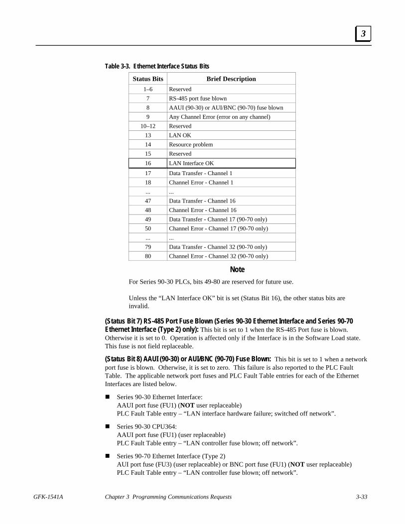
GFK-1541A Chapter 3 Programming Communications Requests 3-33
3
Table 3-3. Ethernet Interface Status Bits
Status Bits Brief Description
1–6 Reserved
7 RS-485 port fuse blown
8 AAUI (90-30) or AUI/BNC (90-70) fuse blown
9 Any Channel Error (error on any channel)
10–12 Reserved
13 LAN OK
14 Resource problem
15 Reserved
16 LAN Interface OK
17 Data Transfer - Channel 1
18 Channel Error - Channel 1
... ...
47 Data Transfer - Channel 16
48 Channel Error - Channel 16
49 Data Transfer - Channel 17 (90-70 only)
50 Channel Error - Channel 17 (90-70 only)
... ...
79 Data Transfer - Channel 32 (90-70 only)
80 Channel Error - Channel 32 (90-70 only)
Note
For Series 90-30 PLCs, bits 49-80 are reserved for future use.
Unless the “LAN Interface OK” bit is set (Status Bit 16), the other status bits areinvalid.
(Status Bit 7) RS-485 Port Fuse Blown (Series 90-30 Ethernet Interface and Series 90-70Ethernet Interface (Type 2) only): This bit is set to 1 when the RS-485 Port fuse is blown.Otherwise it is set to 0. Operation is affected only if the Interface is in the Software Load state.This fuse is not field replaceable.
(Status Bit 8) AAUI (90-30) or AUI/BNC (90-70) Fuse Blown: This bit is set to 1 when a networkport fuse is blown. Otherwise, it is set to zero. This failure is also reported to the PLC FaultTable. The applicable network port fuses and PLC Fault Table entries for each of the EthernetInterfaces are listed below.
n Series 90-30 Ethernet Interface:AAUI port fuse (FU1) (NOT user replaceable)PLC Fault Table entry – “LAN interface hardware failure; switched off network”.
n Series 90-30 CPU364:AAUI port fuse (FU1) (user replaceable)PLC Fault Table entry – “LAN controller fuse blown; off network”.
n Series 90-70 Ethernet Interface (Type 2)AUI port fuse (FU3) (user replaceable) or BNC port fuse (FU1) (NOT user replaceable)PLC Fault Table entry – “LAN controller fuse blown; off network”.

3-34 TCP/IP Ethernet Communications for the Series 90 PLC User's Manual – April 1999 GFK-1541A
3
Operation on other ports is not affected. This problem can be caused by a defective transceiver,shorted network or transceiver cable, or a defective Ethernet Interface. Isolate and correct thecause of the problem, and then replace the fuse or the Ethernet Interface.
Refer to Chapter 2, “Installing the Ethernet Interface”, for fuse type and replacement procedures.
(Status Bit 9) Any Channel Error: This bit is set to 1 if there is presently an error on any of theestablished channels; i.e., if the individual Channel Error bit is set for any channel.
(Status Bit 13) LAN OK: This input will be held at the value 1 as long as the Ethernet Interfacesoftware is able to communicate on the network. If the network should become inaccessible fromthis Interface, due either to local or network problems, this bit will be set to 0. If LANcommunication becomes possible, it is set to 1.
(Status Bit 14) Resource Problem: This input is set to 1 whenever the Ethernet Interfacesoftware experiences a resource problem (i.e., lack of data memory). The bit is reset to 0 on asubsequent PLC sweep. The Ethernet Interface may or may not be able to continue functioning,depending on the severity of the problem. Use the PLC Fault Table to understand the problem.See Chapter 6, “Troubleshooting”, for further information. In addition, you can use the StationManager STAT B and LOG commands to further understand the problem. See the StationManager Manual, GFK-1186, for more information.
(Status Bit 16) LAN Interface OK Bit: This input is set to 1 by the Ethernet Interface each PLCscan. If the Ethernet Interface cannot access the PLC, the CPU will set this bit to 0. When this bitis 0, all other Ethernet Interface Status bits are invalid.
Each channel has a dedicated pair of bits as follows:
(Status Bits 17, 19, 21 ... 79) Data Transfer Bit: This bit is normally set to 0. It is pulsed to 1and back to 0 on successive PLC scans each time a transfer completes successfully. Do notassume that when the Data Transfer bit goes to 1 that a transfer has just completed during thelast scan. The Data Transfer bit is not closely synchronized in time with the transfer. The bitonly indicates that a transfer has occurred during the preceding read (or write) period. A risingedge on the Data Transfer bit indicating that a transfer has completed successfully does notguarantee that the next transfer has not begun or completed. In the case of an Establish Channelcommand, the CRS word is always updated before the Data Transfer bit is set to 1.
(Status Bits 18, 20, 22 ... 80) Channel Error Bit: This bit is set to 1 when an error is detected onthis channel. It is set to 0 when the channel is initially established and if the channel resumesnormal operation after a transient error condition subsides. The Channel Error bit is also set to 0when the channel is aborted by an Abort Channel command or when the PLC CPU transitionsfrom RUN to STOP. In the case of an Establish Channel command, the CRS word is alwaysupdated before the Channel Error bit is set to 1.
Note
For Series 90-30 PLCs, bits 49-80 are reserved for future use.

GFK-1541A Chapter 3 Programming Communications Requests 3-35
3
Communications Status Words
The COMMREQ Status word (CRS word) and the first word of the two Detailed Channel Statuswords (DCS words) report status and errors in the same format, as shown below. The secondword of the DCS words indicates when the channel is active.
The CRS word location is specified in Words 3 and 4 of the Command Block. The DCS wordslocation is specified in the Retrieve Detailed Channel Status Command. The contents of thesestatus words are defined below:
The initial value of the Detailed Channel Status words is all zeros. DCS words are reset to zerowhen:
n The Ethernet Interface is powered up or restartedn The CPU transitions from STOP to RUNn A channel abort COMMREQ aborts the channel
Hex Format
High Low
00 00
Minor Error Codes (high byte)
Success and Major Error Codes (low byte)
CRS Word in
Figure 3-3. Format of the COMMREQ Status Word (CRS Word)
High Low
00 00
Minor Error Codes (high byte)
Success and Major Error Codes (low byte)
0000
Channel Active (0001 = channel active,0000 = channel not active)
DCS Word in Hex FormatWord 1Word 2
Figure 3-4. Format of the Detailed Channel Status Words (DCS Words)
There are several points to remember when interpreting the contents of the COMMREQ Statusword and Word 1 of the Detailed Channel Status words:
1. Display the Status Words in hexadecimal form to more easily differentiate the high and lowbytes. A good way to do this is to use a MOVE WORD function block to display thehexadecimal value within the ladder program.
2. The Ethernet Interface will never send a zero for the COMMREQ Status word to the PLCCPU. The user program should zero the COMMREQ Status word before issuing theCOMMREQ function and then check for a non-zero value indicating that the EthernetInterface is responding to the COMMREQ. A good way to do this is to use a MOVE WORDfunction block to zero the CRS word.

3-36 TCP/IP Ethernet Communications for the Series 90 PLC User's Manual – April 1999 GFK-1541A
3
3. A status code of 1 in the low byte and 0 in the high byte indicates that the request wassuccessful. All other non-zero values indicate errors. Refer to the tables below for a completelisting of major and minor error codes.
The following tables list the error codes that are reported in the COMMREQ Status word after theexecution of a COMMREQ function. These codes also may appear in Word 1 of the DetailedChannel Status words.
Table 3-4. Major Error Codes
Error Status Major Error DescriptionHexadecimal
01H Successful Completion. (This is the expected completion value in theCOMMREQ Status word.)
02H Insufficient Privilege at server PLC. For a Series 90-70 server PLC, theminor error code contains the privilege level required for the service request.
04H Protocol Sequence Error. The server CPU has received a message that is outof order. Call GE Fanuc Automation - NA for assistance.
05H Service Request Error at server PLC. The minor error code contains thespecific error code. See the following table of Minor Error codes.
06H Illegal Mailbox Type at server PLC. Service request mailbox type is eitherundefined or unexpected. Call GE Fanuc Automation - NA for assistance.
07H The server PLC CPU’s Service Request Queue is full, usually due to heavyCPU loading. The client should retry later. It is recommended that theclient wait a minimum of 10 milliseconds before sending another servicerequest.
0BH Illegal Service Request. The requested service is either not defined or notsupported at the server PLC. (This value is returned in lieu of the actualservice request error (01H), to avoid confusion with the normal successfulCOMMREQ completion.) Call GE Fanuc Automation - NA for assistance.
11H SRTP Error Codes at server. An error was detected at the SRTP server.See the following table of Minor Error codes.
82H Insufficient Privilege at client PLC. For the Series 90-70 PLC, the minorerror code contains the privilege level required for the service request.
84H Protocol Sequence Error. The CPU has received a message that is outof order. Call GE Fanuc Automation - NA for assistance.
85H Service Request Error at the client PLC. The minor error code contains thespecific error code. See the following table of Minor Error codes.
86H Illegal Mailbox Type. Service request mailbox type is either undefined orunexpected. Call GE Fanuc Automation - NA for assistance.
87H The client PLC CPU’s Service Request Queue is full. The client shouldretry later. It is recommended that the client wait a minimum of 10milliseconds before sending another service request.
8BH Illegal Service Request. The requested service is either not defined or notsupported. (This value is returned in lieu of the actual service request error(01H), to avoid confusion with the normal successful COMMREQcompletion.). Call GE Fanuc Automation - NA for assistance.
90H Client API error. See the following table of Minor Error codes.

GFK-1541A Chapter 3 Programming Communications Requests 3-37
3
Minor Error Codes
The meaning of each Minor Error Code depends upon the Major Error Code for which it isdefined. Consult the appropriate Minor Error Code table for the indicated Major Error Code.
Table 3-5. Minor Error Codes for Major Error Codes 05H (at Remote Server PLC) and85H (at Client PLC)
Error Status Service Request Error Description(Hexadecimal)
C105H/C185H Invalid block state transition.C305H/C385H Text length does not match traffic type.C605H/C685H Control Program (CP) tasks exist but requestor not logged into main CP.C705H/C785H Passwords are set to inactive and cannot be enabled or disabled.C805H/C885H Password(s) already enabled and cannot be forced inactive.C905H/C985H Login using non-zero buffer size required for block commands.CA05H/CA85H Device is write-protected.CB05H/CB85H A comm or write verify error occurred during save or restore.CC05H/CC85H Data stored on device has been corrupted and is no longer reliable.CD05H/CD85H Attempt was made to read a device but no data has been stored on it.CE05H/CE85H Specified device has insufficient memory to handle request.CF05H/CF85H Specified device is not available in the system (not present).D105H/D185H Packet size or total program size does not match input.D205H/D285H Invalid write mode parameter.D505H/D585H Invalid block name specified in datagram.D605H/D685H Total datagram connection memory exceeded.D705H/D785H Invalid datagram type specified.D805H/D885H Point length not allowed.D905H/D985H Transfer type invalid for this Memory Type selector.DA05H/DA85H Null pointer to data in Memory Type selector.DB05H/DB85H Invalid Memory Type selector in datagram.DC05H/DC85H Unable to find connection address.DD05H/DD85H Unable to locate given datagram connection ID.DE05H/DE85H Size of datagram connection invalid.DF05H/DF85H Invalid datagram connection address.E005H/E085H Service in process cannot login.E405H/E485H Memory Type for this selector does not exist.E905H/E985H Memory Type selector not valid in context.EA05H/EA85H Not logged in to process service request.EE05H/EE85H Could not return block sizes.EF05H/EF85H Programmer is already attached.F005H/F085H Request only valid in stop mode.F105H/F185H Request only valid from programmer.F205H/F285H Invalid program cannot log in.F405H/F485H Invalid input parameter in request.F505H/F585H Invalid password.F605H/F685H Invalid sweep state to set.

3-38 TCP/IP Ethernet Communications for the Series 90 PLC User's Manual – April 1999 GFK-1541A
3
Table 3-5. Minor Error Codes for Major Error Codes 5H and 85H (Continued)
Error Status Service Request Error Description(Hexadecimal)
F705H/F785H Required to log in to a task for service.F805H/F885H Invalid task name referenced.F905H/F985H Task address out of range.FC05H/FC85H I/O configuration is invalid.FE05H/FE85H No privilege for attempted operation.FF05H/FF85H Service request has been aborted.
Table 3-6. Minor Error Codes for Major Error Code 11H (at Remote Server PLC)Error Status SRTP Error Description(hexadecimal)
0111H Generic SRTP error.0211H The PLC is inaccessible.0311H Reserved.0411H Unexpected SRTP version encountered in received message.0511H Unrecognized SRTP message received.0611H Data present in SRTP message which should not contain data.0711H Generic resource problem detected.0811H SRTP message encountered in inappropriate connection state.0911H Generic refusal by backplane driver to handle request.0A11H Recognized but unsupported SRTP message received.0B11H Lost transaction in server.1411H Request failed due to an error in the remote device. The Remote
device log will have more information.2411H Invalid Address found in message sent to backplane driver.2711H Backplane driver not initialized.2A11H The backplane driver could not access the PLC.2B11H Invalid binding on the message sent to the backplane driver.2C11H The message could not be sent to its destination because the mailbox was
not open.2D11H The maximum number of transfers to the destination is already taking
place.2E11H The maximum number of transfers of this transfer type is
already taking place.2F11H Cannot obtain a backplane transfer buffer.3011H Cannot obtain resources other than backplane transfer buffers.3111H Connection ID or block transfer ID is not valid.3211H Timed out waiting for PLC CPU response.3311H The PLC CPU aborted the request.3411H An invalid message type was specified.3511H The specified task is not registered.3611H The mailbox offset specified is invalid.3A11H More than the allowable byte length in a single transfer.3B11H Bad sequence number in the request.3C11H Invalid command in request.3F11H Request failed due to error on remote device, most likely running
out of Dual-Port RAM text buffers.FE11H Request failed due to mailbox error on remote device. The remote device
log will have more information.

GFK-1541A Chapter 3 Programming Communications Requests 3-39
3
Table 3-7. Minor Error Codes for Major Error Code 90H (at Client PLC)
Error Status Application Interface Error Description(Hexadecimal)
0190H Timeout expired before transfer completed; still waiting on transfer.0290H Period expired before transfer completed; still waiting on transfer.8190H COMMREQ data block too short for the command.8290H COMMREQ data block too short for server PLC node address.8390H Invalid server memory type.8490H Invalid Program Name.8590H Invalid Program Block Name.8690H Zero server unit length is not allowed.8790H Server unit length is too large.8890H Invalid channel number.8990H Invalid time unit for period. (Maximum permitted 3965 hours)8A90H Period value is too large.8B90H Zero server memory starting address is not allowed.8C90H Invalid client memory type.8D90H Invalid server host address type.8E90H Invalid IP address integer value. (Must be 0–255)8F90H Invalid IP address class.9090H Insufficient TCP connection resources to do request.9190H Zero local starting address is not allowed.9290H Address length value invalid. Must be 4 for address type.9390H COMMREQ data block too short for Program Block name
(including 0 pad).9490H COMMREQ data block too short for Program name
(including 0 pad).9590H Internal API error. See PLC Fault Table or exception log for details. This problem may
occur due to the Ethernet Interface being asked to perform beyond its capacity. Trytransferring less data per message or establishing fewer simultaneous connections.
9690H Underlying TCP connection aborted (reset) by server end point.9790H Underlying TCP connection aborted by client end point.9890H The remote server has no Service Request Processor.9A90H Response to session request did not arrive in proper order.9B90H Session denied by server PLC.9C90H Data response did not arrive in proper order.9D90H Data response had unexpected size.9E90H Unrecognized COMMREQ command code.A190H Invalid CRS word memory type.A290H Failed an attempt to update the CRS word.A490H Address length value invalid. Must be 32 for Network Address name type.B090H Network Address name length error. The name cannot exceed 31 ASCII
characters and must be terminated with a NUL character (zero).B190H Specified Network Address name could not be resolved into an IP address.B390H Internal name resolution error. See PLC Fault Table or exception log for details.

3-40 TCP/IP Ethernet Communications for the Series 90 PLC User's Manual – April 1999 GFK-1541A
3
Section 5: Controlling Communications in the Ladder Program
This section provides tips on how to control communications in your ladder program. Onlysegments of actual ladder logic are included. Topics discussed are:
n Essential Elements of the Ladder Program
n Troubleshooting Your Ladder Program
n Monitoring the Communications Channel
n Managing Channels and TCP Connections
Essential Elements of the Ladder Program
Every ladder program, whether in the developmental phase or the operational phase, should dothe following before initiating a COMMREQ function.
1. Initiate the COMMREQ function with a one-shot transitional coil (or transitional contact forSeries 90-70 PLCs). This prevents accidentally sending the same COMMREQ CommandBlock more than once.
2. Include at least the LAN Interface OK bit in the LAN Interface Status Word as an interlockcontact for the COMMREQ function. You may choose to add more interlocks.
3. Zero the word location you specify for the COMMREQ Status (CRS) word, and the OK(Series 90-70 PLCs only) and FT Outputs of the COMMREQ Function Block before theCOMMREQ function is initiated.
4. Move the command code and parameters for the Channel command into the memory locationspecified in IN input of the COMMREQ Function Block before the COMMREQ function isinitiated.
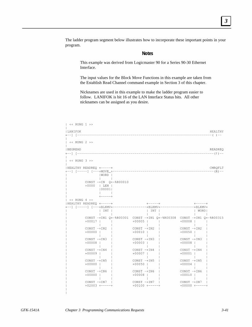
GFK-1541A Chapter 3 Programming Communications Requests 3-41
3
The ladder program segment below illustrates how to incorporate these important points in yourprogram.
Notes
This example was derived from Logicmaster 90 for a Series 90-30 EthernetInterface.
The input values for the Block Move Functions in this example are taken fromthe Establish Read Channel command example in Section 3 of this chapter.
Nicknames are used in this example to make the ladder program easier tofollow. LANIFOK is bit 16 of the LAN Interface Status bits. All othernicknames can be assigned as you desire.
| << RUNG 1 >>||LANIFOK HEALTHY+——] [————————————————————————————————————————————————————————————————————( )——|| << RUNG 2 >>||BEGREAD READREQ+——] [—————————————————————————————————————————————————————————————————————(↑)——|| << RUNG 3 >>||HEALTHY READREQ +—————+ CMRQFLT+——] [—————] [———+MOVE_+———————————————————————————————————————————————————(R)——| |WORD || | || CONST —+IN Q+—%R00010| +0000 | LEN || |00001|| | || +—————+| << RUNG 4 >>|HEALTHY READREQ +—————+ +—————+ +—————++——] [—————] [———+BLKMV+—————————————————+BLKMV+—————————————————+BLKMV+| | INT | | INT | | WORD|| | | | | | || CONST —+IN1 Q+—%R00301 CONST —+IN1 Q+—%R00308 CONST —+IN1 Q+—%R00315| +00017 | | +00005 | | +00008 | || | | | | | || CONST —+IN2 | CONST —+IN2 | CONST —+IN2 || +00000 | | +00010 | | +00050 | || | | | | | || CONST —+IN3 | CONST —+IN3 | CONST —+IN3 || +00008 | | +00003 | | +00008 | || | | | | | || CONST —+IN4 | CONST —+IN4 | CONST —+IN4 || +00009 | | +00007 | | +00001 | || | | | | | || CONST —+IN5 | CONST —+IN5 | CONST —+IN5 || +00000 | | +00050 | | +00004 | || | | | | | || CONST —+IN6 | CONST —+IN6 | CONST —+IN6 || +00000 | | +00008 | | +00010 | || | | | | | || CONST —+IN7 | CONST —+IN7 | CONST —+IN7 || +02003 +—————+ +00100 +—————+ +00000 +—————+||

3-42 TCP/IP Ethernet Communications for the Series 90 PLC User's Manual – April 1999 GFK-1541A
3
| << RUNG 5 >>||HEALTHY READREQ +————–++——] [—————] [———+BLKMV+—| | INT || | || CONST —+IN1 Q+—%R00322| +00000 | || | || CONST —+IN2 || +00001 | || | || CONST —+IN3 || +00000 | || | || CONST —+IN4 || +00000 | || | || CONST —+IN5 || +00000 | || | || CONST —+IN6 || +00000 | || | || CONST —+IN7 || +00000 +—————+|| << RUNG 6 >>||HEALTHY READREQ +—————++——] [—————] [———+COMM_+—| | REQ || | | CMRQFLT| %R00301—+IN FT+———————————————————————————————————————————————————(S)| | || CONST | || 0004—+SYSID|| | || CONST —+TASK || 00000000 +—————+|
Rung # 1: Input LANIFOK (bit 16 of the LAN Interface Status bits) monitors the health of theEthernet Interface. If it is OK to send a COMMREQ, the HEALTHY coil is ON. HEALTHY isused as an interlock for Rungs 3–6.
Rung # 2: Input BEGREAD triggers READREQ, which enables execution of the MOVE andCOMMREQ functions. READREQ is a one-shot coil, activating once when BEGREADtransitions from OFF to ON.
Rung # 3: The MOVEWORD function moves a zero to the CRS word referenced in theCommand Block (see rung #4). This clears the CRS word. This rung also resets the FT outputcoil of the COMMREQ Function Block in rung #6.
It is vital that the CRS Status Word be cleared and the COMMREQ fault output coil be clearedeach time before initiating a COMMREQ function.
Rungs # 4–5: The BLKMVINT functions set up the COMMREQ Command Block contents.When these rungs are activated, the constant operands are moved into the memory beginning atthe address indicated in the instruction. The constant operands in this example are defined in theEstablish Read Channel Example in Section 3 of this chapter.

GFK-1541A Chapter 3 Programming Communications Requests 3-43
3
Rung # 6: The COMMREQ Function Block has three input parameters and one output parameter(two output parameters for Series 90-70 PLCs).
n The IN field points to the starting location of the Command Block parameters (%R00301 inthis example).
n The SYSID field of the COMMREQ Function Block defines the target rack and slot of theEthernet Interface to receive the command data. The first two digits of SYSID (00 in thisexample) indicate the rack number, the last two digits (04 in this example) indicate the slotnumber of the Ethernet Interface. (For the Series 90-30 CPU364, this value should always beset to 0001 to specify rack 0, slot 1.)
n The TASK field of the COMMREQ Function Block indicates which mailbox task ID to usefor the specified rack and slot. For the Series 90-30 Ethernet Interface and the Series 90-70Ethernet Interface (Type 2), this value should always be zero. For the Series 90-30 CPU364,this value should always be 21 decimal (0015H).
n The FT output (CMRQFLT in this example) is turned ON (set to 1) if there were problemspreventing the delivery of the Command Block to the Ethernet Interface. In this case, theother status indicators are not updated for this COMMREQ. For Series 90-70 PLCs only, theOK output may also be monitored to verify the COMMREQ was successfully sent to theEthernet Interface.
Troubleshooting Your Ladder Program
As explained in Section 4 of this chapter, there are several forms of status data which can be usedin your ladder program. The use of the LAN Interface OK bit in the LAN Interface Status Wordwas described in the ladder program fragment above. Some of the status data can be used totroubleshoot your program in its developmental stage. The two primary sources of this data arethe FT Output on the COMMREQ Function Block and the COMMREQ Status word (CRS word).
FT Output is ON
If after executing a COMMREQ Function, the FT Output is ON, then there is a programmingerror in one or more of the following areas.
n Invalid rack/slot specified. The module at this rack/slot is unable to receive a COMMREQCommand Block.
n Invalid Task ID. For the Series 90-30 Ethernet Interface and the Series 90-70 EthernetInterface (Type 2), this value should always be zero. For the Series 90-30 CPU364, this valueshould always be 21 decimal (0015H).
n Invalid Data Block length (0 or greater than 128).
COMMREQ Status Word is Zero (0) and FT Output is OFF
If after executing a COMMREQ function, the CRS word is zero (0) and the FT Output is OFF,then the Command Block has been sent to the Ethernet Interface, but no status has been returnedyet. If this condition persists, check the PLC Fault Table for information.

3-44 TCP/IP Ethernet Communications for the Series 90 PLC User's Manual – April 1999 GFK-1541A
3
COMMREQ Status Word is Not One (1)
If after executing a COMMREQ function, the CRS word is not one (1) indicating success, thenthere were:
n Errors in the Command Block (the Channel command code or parameters), or
n For an establish command (Establish Read Channel, Establish Write Channel, or SendInformation Report), the command parameters were valid but there was an error inestablishing a channel.
If the CRS word does not contain a 1 indicating success, then it contains either a 0 or a codeindicating what error occurred. See Section 4 of this chapter for CRS word error codes.
Monitoring the Communications Channel
Once you have a working ladder program, you can use the status data to monitor yourcommunications activity and take the desired action upon certain events. The primary indicatorsof a communications channel are the Channel Status bits: Channel Error bit and Data Transferbit. In addition, the CRS word and the DCS words can be used to more precisely troubleshoot anyproblems that may occur.
Monitoring the COMMREQ Status Word
It is critical to monitor the CRS word for each COMMREQ function you initiate. First, zero theassociated CRS word before executing the COMMREQ function. Then when the CRS wordbecomes non-zero, you know the Ethernet Interface has updated it. If the CRS word is updated toa one (1), then the Command Block was processed successfully by the Ethernet Interface. If theCRS word is updated to a value other than 1, then an error has occurred in processing theCommand Block. See Section 4 of this chapter for CRS word error codes.
Do not use data received from a server until the CRS word for that channel is 1 or the DataTransfer bit goes to 1.
Monitoring the Channel Error Bit
This bit (normally 0) is the primary indicator for an error on a channel. It indicates any channelerror, fatal or non-fatal. It does not necessarily indicate that the channel is down (idle). If this bitindicates an error:
n Initiate the Abort command and then reinitiate the Read or Write command, or if the errorpersists,
n Initiate the Retrieve Detailed Channel Status command to find out if the channel is down andpossibly why it went down.
Keep in mind, however, that the status code may change from between the time the Channel Errorbit indicates an error and the time the Retrieve Detailed Channel Status command retrieves thecode.

GFK-1541A Chapter 3 Programming Communications Requests 3-45
3
The Channel Error bit for a channel is not meaningful until after the Ethernet Interface updatesthe CRS word confirming the Read or Write command for that channel. In the case of anEstablish Channel command, the CRS word is updated before the Channel Error bit is set to 1.

3-46 TCP/IP Ethernet Communications for the Series 90 PLC User's Manual – April 1999 GFK-1541A
3
Monitoring the Data Transfer Bit
Typically you will set up a channel to perform repetitive reads or writes. The Data Transfer bitpulses ( 0 → 1 → 0) each time there is a successful read or write. This can be an indicator to theladder program to move the most recent data to another location.
The Data Transfer bit for a channel is not meaningful until after the Ethernet Interface updatesthe CRS word confirming the Read or Write command for that channel.
Do not use data received from a server until the CRS word confirming the Read command for thatchannel is 1 or the Data Transfer bit goes to 1. Do not assume that when the Data Transfer bitgoes to 1 that a transfer has just completed during the last scan. The Data Transfer bit is notclosely synchronized in time with the transfer. The bit only indicates that a transfer has occurredin a past scan. A rising edge on the Data Transfer bit indicating that a transfer has completedsuccessfully does not guarantee that the next transfer has not begun or completed.
Sequencing Communications RequestsIf the Ethernet Interface receives Command Blocks from the PLC CPU faster than the Interfacecan process them, the Interface will log an exception event 08, Entry 2=0024H and will log thePLC Fault Table entry:
“Backplane Communications with PLC Fault; Lost Request”
Only one COMMREQ function per channel can be pending at one time. A COMMREQ functionis pending from the time it is initiated in the ladder program until its CRS word has been updatedto a non-zero value by the Ethernet Interface.
Managing Channels and TCP Connections
In Certain Conditions TCP Connections Can Be Totally Consumed
When you issue a COMMREQ to establish a read or write channel, a TCP connection is created,the transfer(s) are made, then upon completion of all the transfers, the TCP connection isterminated. It takes time to create and to terminate these connections. If an application isconstructed so that it rapidly and repeatedly establishes a channel with only one repetition (onetransfer), the available TCP connections for the Ethernet Interface may be totally consumed. A“snapshot” of the state of the TCP connections would show some of them being created, somebeing terminated, and some active, but none available.
Specifically, if your ladder program for issuing COMMREQs is constructed so it does thefollowing, all available TCP connections can quickly be used up:
n The number of repetitions (Word 9 in an Establish Read or Write Channel COMMREQ) isset to 1, and
n A new COMMREQ is issued repeatedly and immediately upon completion of the prior one.

GFK-1541A Chapter 3 Programming Communications Requests 3-47
3
Use “Channel Re-Tasking” To Avoid Using Up TCP Connections
The most likely scenario for using up TCP connections is when each successive COMMREQ isdirected to the same target device (same IP address or Network Address name). In this case, it isbetter to establish a channel with the target device once, leave it active, then re-task the channel,even if data transfers take place infrequently. This method will use only one TCP connection.
An additional advantage of re-tasking is that the time and network traffic required to create achannel and its associated TCP connection are not incurred each time a data transfer is required.
The disadvantages to re-tasking are:
n While the TCP connection is open, it is unavailable to the rest of your application, and
n The active TCP connection uses up network bandwidth because the active TCP connectiongenerates a small amount of ongoing periodic network traffic.
How To Re-Task a Channel
1. For Establish Read/Write Channel Commands, set the number of repetitions (COMMREQWord 9) to 2 and set the read/write period (COMMREQ Words 10 and 11) to be longer thanthe expected time between transfers. For example, if you expect to transfer data about onceper minute, set the read/write period to about two minutes. This will cause a TCP connectionto be created and held open for two minutes.
2. Set up the ladder program to:
A. Issue the first COMMREQ and wait for the first transfer to complete, which will beindicated when the COMMREQ Status (CRS) word is changed to 1.
B. Then before the read/write period expires (at which time the second and final transfer issent and the TCP connection is dropped), issue the next COMMREQ with the sameparameters as specified in step 1. This will “re-task” the channel to use the existing TCPconnection instead of opening a new one, and will send another data transfer restartingthe timer for the read/write period. Repeat step 2B for each successive data transferdesired.

GFK-1541A 4-1
Ethernet Global Data
Note
Ethernet Global Data is currently supported on the Series 90-70 EthernetInterface (Type 2) and the Series 90-30 CPU364.
This chapter discusses how to plan and configure an Ethernet Global Data (EGD) system. Thechapter is divided into the following sections:
Section 1. Overview of EGD
Section 2. Configuring EGD
Section 3. Adapter Names, Aliases, and Groups
Section 4. Exchange Status Word
Section 5. Simple Network Time Protocol (SNTP)
4Chapter
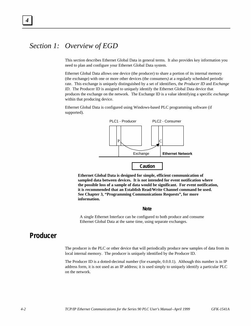
4-2 TCP/IP Ethernet Communications for the Series 90 PLC User's Manual – April 1999 GFK-1541A
4
Section 1: Overview of EGD
This section describes Ethernet Global Data in general terms. It also provides key information youneed to plan and configure your Ethernet Global Data system.
Ethernet Global Data allows one device (the producer) to share a portion of its internal memory(the exchange) with one or more other devices (the consumers) at a regularly scheduled periodicrate. This exchange is uniquely distinguished by a set of identifiers, the Producer ID and ExchangeID. The Producer ID is assigned to uniquely identify the Ethernet Global Data device thatproduces the exchange on the network. The Exchange ID is a value identifying a specific exchangewithin that producing device.
Ethernet Global Data is configured using Windows-based PLC programming software (ifsupported).
PLC1 - Producer PLC2 - Consumer
P C
Exchange Ethernet Network
Caution
Ethernet Global Data is designed for simple, efficient communication ofsampled data between devices. It is not intended for event notification wherethe possible loss of a sample of data would be significant. For event notification,it is recommended that an Establish Read/Write Channel command be used.See Chapter 3, “Programming Communications Requests”, for moreinformation.
Note
A single Ethernet Interface can be configured to both produce and consumeEthernet Global Data at the same time, using separate exchanges.
Producer
The producer is the PLC or other device that will periodically produce new samples of data from itslocal internal memory. The producer is uniquely identified by the Producer ID.
The Producer ID is a dotted-decimal number (for example, 0.0.0.1). Although this number is in IPaddress form, it is not used as an IP address; it is used simply to uniquely identify a particular PLCon the network.

GFK-1541A Chapter 4 Ethernet Global Data 4-3
4
Configuring the Producer ID
The Producer ID is configured via the Local Producer ID field in the Ethernet Global Data RackOperation of the PLC programming software. A default Producer ID value is provided. You canchange the value of the Producer ID from the default value to any number in dotted-decimal form.To ensure uniqueness on the network, the default value is:
Series 90-70 PLCs
The same as the IP address of the Ethernet Interface physically closest to the CPU in the rack.
Series 90-30 PLCs
The same as the IP address of the CPU364 with Embedded Ethernet Interface.
Note
When you configure the producer of Ethernet Global Data, you must also supplythe adapter name of the Ethernet Interface from which the exchange will flow.This name is configured using the PLC programming software (if supported).You need to specify the adapter name because in Series 90-70 PLCs, more thanone Ethernet Interface that supports Ethernet Global Data can be installed.
Consumer
The consumer is the PLC or other device that will update its local internal memory based on thedata in an exchange. The consumer is identified at the producer by a Group ID, an IP address, or asymbolic name. These identifiers refer to the specific Ethernet Interface in the consumer. (ForSeries 90-70 PLCs there can be more than one Ethernet Interface that supports Ethernet GlobalData installed in the PLC.)
Group ID: This method is typically used when you want more than one consumer to receive thesame exchange from a producer. See the topic “Group Usage” for more information.
IP Address: This method is used when you want to identify the consumer’s Ethernet Interfaceusing an IP address.
Symbolic Name: This method is used when you want to use either local table, DDP, or DNSname resolution to acquire the consumer’s IP address. See the topic “Name Resolution” in Chapter5, “Network Administration Support”, for more information.

4-4 TCP/IP Ethernet Communications for the Series 90 PLC User's Manual – April 1999 GFK-1541A
4
Exchange
The exchange refers to a set of variables or memory locations that contain an internal snapshot ofmemory within the PLC or other device. The Exchange ID is the value you assign to a particularexchange that identifies it uniquely within a particular producer. You must configure an exchangein both the producer and the consumer.
Configuring the Exchange
Exchanges are configured by filling out parameters in the Ethernet Global Data dialog box of thePLC programming software for both the producer and consumer and storing the configuration tothe PLC. These parameters define the content of an exchange as well as its operationalcharacteristics. A variable that has already been created in hardware configuration, the programeditors, or the Variable Declaration Editor window can be used in an exchange. Or, you can createnew variables in the Ethernet Global Data dialog box.

GFK-1541A Chapter 4 Ethernet Global Data 4-5
4
Asynchronous Operation of EGDThe production and consumption of EGD is asynchronous. The period timers for the producer andconsumer are independent of each other. In addition, the initiation of the production andconsumption of EGD can occur at different times.
The figure below illustrates the asynchronous aspect of EGD.
• SVCREQ Status word is set to 1(Logic-Based EGD only).
• Producer period timer starts.
• Exchange Status word is set to 0.
• First exchange data sample is sentonto the network.
PLC Producing EGD PLC Consuming EGD
EGD Production Is Initiated
EGD Consumption is Initiated
• SVCREQ Status word is set to 1(Logic-Based EGD only).
• Consumer period timer starts.• Exchange Status word is set to 0.
EGD Consumption Repeats
• Consumer period timer expires andis restarted.
• Exchange data sample receivedfrom the network is updated inconsumer PLC memory.
• Exchange Status word is set to 1(or 3 if SNTP timestamping is used).
EGD Production Repeats
• Producer period timer expires and isrestarted.
• Exchange data sample is sent ontothe network.
• Exchange Status Word set to 1.
• Consumer period timer expires andis restarted.
• Exchange data sample receivedfrom the network is updated inconsumer PLC memory.
• Exchange Status word is set to 1(or 3 if SNTP timestamping is used).
• Producer period timer expires and isrestarted.
• Exchange data sample is sent ontothe network.
• Exchange Status Word set to 1.
Producerperiod
Producerperiod
Consumerperiod
Consumerperiod
via LAN
Figure 4-1. Successful Operation of EGD
Note
The figure above presents a simplified overview of EGD. There are other timingissues regarding data transferred from the Ethernet Interface to the PLC CPU thatcould be an issue depending on your application. See the topic, “ConfigurationPlanning,” for more information.

4-6 TCP/IP Ethernet Communications for the Series 90 PLC User's Manual – April 1999 GFK-1541A
4
Effect of PLC Modes and Actions on EGD Operations
The table below indicates what happens to the configuration and operation of EGD when indifferent PLC modes and when certain PLC actions take place.
For example, the normal PLC mode for EGD operation is RUN with Outputs enabled. In this PLCmode, EGD remains configured and exchanges are both produced and consumed. If the PLC modeis set to STOP with I/O disabled, the Producer ID remains configured, but production andconsumption stop.
When configuration is lost, the EGD configuration must be stored again.
Table 4-1. Effect of PLC Modes and Actions on EGD Operations
Configuration-Based Exchangescontinue to be…
PLC Mode or Action
Producer ID remainsconfigured if…
Configured Produced Consumed
PLC Mode
RUN-Outputs Enabled YES YES YES YES
RUN-Outputs Disabled YES YES NO YES
RUN-SUSPEND I/O 1 YES YES NO NO
STOP-I/O Enabled YES YES YES YES
STOP-I/O Disabled YES YES NO NO
PLC Action
RUN-Store Logic YES YES NO3 NO3
STOP-Store Logic YES YES NO3 NO3
STOP-Clear Logic YES YES NO3 NO3
STOP-Config Store Replaced2 Replaced2 NO3 NO3
STOP-Clear Config NO NO NO NO
PLC Power Cycle YES YES NO3 NO3
Ethernet InterfaceRestart
YES YES NO3 NO3
1 RUN-SUSPEND I/O refers to the SUSIO logic function.2 Producer ID and exchange definitions are replaced.3 Producer ID and exchanges continue to be configured or not depending on the PLC mode prior to the action.
Note
The DOIO logic function does not affect EGD production or consumption.
GFK-1541A Chapter 4 Ethernet Global Data 4-7
4
Configuration PlanningProducer and Consumer Periods for PLCs
Follow these guidelines for the producer and consumer periods.
n Set the producer period and the consumer period to the same value. This makes thesystem easier to troubleshoot and makes network resource usage more efficient.
n Do not produce and consume data faster than is required by your application. Thisreduces the load on the network and on the devices, providing capacity for other transfers. Forexample, an exchange intended for an HMI host usually does not need to be produced anyfaster than 500 milliseconds or so. In fact, a 1 to 3 second producer period may be sufficientfor this case.
Exchange Limitations and Recommendations
The limitations and recommendations for consumer and producer exchanges are as follows:
Maximum Number of Exchanges
The maximum number of exchanges can be divided up into any combination of producer andconsumer exchanges.
n For a single Series 90-70 PLC system, which may contain multiple Ethernet Interfaces, themaximum combined number of exchanges that can be configured is 255.
n For the Series 90-30 CPU364, the maximum number of exchanges that can be configured is128.
Maximum Data Size of an Exchange
The total data size of a single exchange cannot exceed 1400 bytes. The total size is defined to bethe sum of the data lengths of all of the variables within the list.
Number of Variables
n Up to 100 variables can be configured per exchange.
n The minimum is one variable per exchange.
n Different exchanges may have different variables, and they may share some or all of the samevariables even if the exchanges are produced and/or consumed at different rates.

4-8 TCP/IP Ethernet Communications for the Series 90 PLC User's Manual – April 1999 GFK-1541A
4
Allowable Data Types in Exchanges
Boolean type variables are not allowed; neither are Boolean-Array variables. If discrete pointreferences such as %I or %Q are used to define a variable, you must define them as Byte-Array,Word-Array, or Dword-Array variables. This implies that a variable consisting of discrete pointreferences must be defined in blocks of 8 points if it is defined as a Byte-Array, 16 points if Word-Array, and 32 points if DWord-Array. See Table 4-2 for valid memory types.
Producer and Consumer Period Ranges
Producer and consumer periods may be configured to be between 10 milliseconds and one hour(inclusively). They should be configured in increments of 10 milliseconds. If not, they arerounded to the next highest 10-millisecond increment during operation. For example, aconfiguration value of 11 (intended to be 11 milliseconds) will be treated the same as 20 ms by theEthernet Interface.
Effect of Enabling User Interrupts
If user interrupts are enabled, the data values of a variable greater than 256 bytes are not guaranteedto be “atomic” (or “coherent”, meaning their snapshot is taken at the same instant). If atomic datatransfer is desired for a variable within the exchange, disable user interrupts or limit the size of thevariable to 256 bytes or less.
Update Timeout Period
Set the update timeout period for the consumer to twice the producer period and at least 20milliseconds greater than the consumer period. Otherwise, the PLC may occasionally falsely reportrefreshment faults. Use zero for the update timeout period of a consumed exchange to disabletimeout detection.

GFK-1541A Chapter 4 Ethernet Global Data 4-9
4
PLC Timing Considerations when using EGD
When designing applications using EGD, it is important to understand that the Ethernet Interfaceand PLC CPU share internal memory for EGD operations. (See the figure below.)
CPU ETHERNETINTERFACE
SHAREDMEMORYINTERNAL
MEMORY
NETWORK
Figure 4-2. The CPU and Ethernet Interface Use Shared Internal Memory for EGD
When producing EGD, the CPU updates shared internal memory with a data sample after its ownperiod timer expires, affecting the length of the PLC sweep only for that particular exchangeupdate. Since an update occurs only once per period, this mode has little effect on the averagesweep time. When the Ethernet Interface’s period timer expires, it produces the data sample fromshared internal memory onto the network. Since the CPU’s period timer and the EthernetInterface’s period timer are asynchronous, a produced data sample could lag somewhat behind theactual content of the CPU reference tables.
In the consumer PLC, shared internal memory is updated as soon as the Ethernet Interface gets adata sample from the network. After the CPU period timer expires, the CPU updates its referencetables from shared internal memory.

4-10 TCP/IP Ethernet Communications for the Series 90 PLC User's Manual – April 1999 GFK-1541A
4
Naming Conventions
If you follow consistent naming conventions for your Ethernet Global Data system, it will be mucheasier to configure EGD. These naming conventions include the following items:
n Equipment Folder Name – This is the name of the program folder that you assign whencreating a hardware configuration and program for a PLC. It can represent the name of a PLC.
n Producer ID – This identifies the EGD producer and is configured in the Ethernet Global Datadialog box.
n Adapter Name – The adapter name is configured in the Module Parameters dialog box for theEthernet Interface. This name is also referenced in the Ethernet Global Data dialog box of thePLC programming software.
n Alias – Configured in the Name Resolution and Routing Table Rack Operation in the PLCprogramming software if you have decided to use local name table name resolution to connectto consumers.
n CCU Device Name – This is the name used by the Communication Configuration Utility(CCU), part of the Windows-based PLC programming software and Host CommunicationToolkit, to identify an Ethernet Interface within a PLC to which you want to connect. Whenyou configure these names, use a name similar to the adapter name of the Ethernet Interface.
When you assign names for these parameters, use names that help to easily recognize theirrelationship to one another.
For example, if you identify the PLCs in your system using an Equipment folder name such asPLC1, PLC2, and so on, it will be easier to recognize these PLCs when configuring EGD if youconfigure Local Producer IDs with numbers such as 0.0.0.1, 0.0.0.2, and so on.
Also, it is recommended to use a similar name for both the adapter name and the CommunicationConfiguration Utility (CCU) device name for an Ethernet Interface. This will make it easier foryou to recognize the PLC you want to connect to for configuring EGD. If you configure the CCUdevice name while an Equipment folder is open, the folder name will be suggested as the CCUdevice name.
Naming Conventions – EXAMPLE
Ethernet Interface(s)Your Name forthe PLC
(EquipmentFolder Name)
LocalProducer ID Network Adapter
NameCCU Device
NameIP Address
PLC1 0.0.0.1 PLC1_A* PLC1_A* 10.0.0.23PLC1 0.0.0.1 PLC1_B* PLC1_B* 10.0.0.34PLC2 0.0.0.2 PLC2 PLC2 10.0.0.41PLC3 0.0.0.3 PLC3 PLC3 10.0.0.50
* There can be more than one Ethernet Interface (Type 2) in a Series 90-70 PLC

GFK-1541A Chapter 4 Ethernet Global Data 4-11
4
Before You Configure EGD ExchangesBefore you begin configuring EGD exchanges you will need to collect a considerable amount ofinformation about the PLCs in your system. It is a good idea to record this data so that when youare ready to configure the exchanges in the PLC programming software, all pertinent informationwill be easily found. The tables that follow represent one way of recording this information. Usethese tables or design your own method for recording the information outlined below.
Record Your EGD System Informationn Determine for each PLC what data needs to be produced and consumed.
n Make a list of the adapter names and IP addresses of the Ethernet Interfaces in the PLCs thatare being used to produce or consume the exchanges. (See the topic “Naming Conventions” ifthese names have not already been configured.)
n Determine whether you will identify EGD consumers using a Group ID, IP address, orsymbolic name.
n If you choose to use symbolic names, you can use either local name table, DDP, or DNS nameresolution.
o Local name table name resolution uses aliases configured locally in each producer PLC inthe Name Resolution and Routing Table Rack Operation in the PLC programmingsoftware (if supported). If using aliases make a list of them.
o DDP uses the adapter name of the remote Ethernet Interface for name resolution. Theadapter name of an Ethernet Interface is assigned in Module Configuration.
o DNS name resolution uses a DNS server at which DNS names are configured. If usingDNS names, make a list of them. Note that DNS names must be different than the adaptername configured for the Ethernet Interface and must be defined at the remote DNS nameserver before use.
See the topic “Name Resolution” in Chapter 5, “Network Administration Support”, for moreinformation.
n Define the exchanges of data you want to configure.
n Make a list of the CCU device names used to connect to the producer and consumer PLCs.(See the topic “Naming Conventions” if these names have not already been configured.) CCUdevice names are the names used to identify the Ethernet Interface as configured in theCommunication Configuration Utility.
Use tables similar to the following to record this information.
Producer/Consumer Information for Entire EGD System – EXAMPLE
Ethernet Interface(s)Your Name forthe PLC
(EquipmentFolder Name)
P C LocalProducer ID Network Adapter
NameCCU Device
NameIP Address
PLC1 X X 0.0.0.1 PLC1_A PLC1_A 10.0.0.23PLC1 X 0.0.0.1 PLC1_B PLC1_B 10.0.0.34PLC2 X 0.0.0.2 PLC2 PLC2 10.0.0.41PLC3 X X 0.0.0.3 PLC3 PLC3 10.0.0.50
P=Producer C=Consumer

4-12 TCP/IP Ethernet Communications for the Series 90 PLC User's Manual – April 1999 GFK-1541A
4
Recording Exchange Information
The produced/consumed exchanges tables below were designed with columns that match up withthe fields in the Ethernet Global Data dialog box.
These tables contain a definition of ALL the exchanges in the entire EGD system. The shadedLocal Producer ID column indicates in which PLC a given exchange is to be configured.
Record Your Produced Exchange Information
The first two rows of data in the Produced Exchanges table indicate that there are two producedexchanges for the PLC identified as 0.0.0.1. The third row of data indicates another exchangeproduced by the PLC identified as 0.0.0.3.
Produced Exchanges Information – EXAMPLE
LocalProducer ID
ExchangeID
Local Adapter Name ConsumerType
ConsumerAddress
SendType
ProducerPeriod
ReplyRate
StatusWord
0.0.0.1 1 PLC1_A IP Address 10.0.0.50 Always 1000 0 Stat10.0.0.1 3 PLC1_B IP Address 10.0.0.41 Always 1000 0 Stat30.0.0.3 2 PLC3 IP Address 10.0.0.23 Always 1000 0 Stat2
Record Your Consumed Exchange Information
The first row of data in the Consumed Exchanges table indicates that there is one consumedexchange for the PLC identified as 0.0.0.1 and that the remote producer is PLC 0.0.0.3. The othertwo rows indicate consumed exchanges in PLCs 0.0.0.2 and 0.0.0.3, each with the remote producer,PLC 0.0.0.1.
Consumed Exchanges Information – EXAMPLE
LocalProducer ID
ExchangeID
Local Adapter Name RemoteProducer ID
GroupID
ConsumerPeriod
UpdateTimeout
StatusWord
TimeStamp
0.0.0.1 2 PLC1_A 0.0.0.3 0 1000 2000 Stat2 Time20.0.0.2 3 PLC2 0.0.0.1 0 1000 2000 Stat3 Time30.0.0.3 1 PLC3 0.0.0.1 0 1000 2000 Stat1 Time1

GFK-1541A Chapter 4 Ethernet Global Data 4-13
4
Section 2: Configuring EGD
This section describes how to configure EGD using the Ethernet Global Data rack operation in theWindows-based PLC programming software (if supported).
The main topics covered are:
n Exchange Definitions
n Configuring Ethernet Global Data (with examples)
Exchange Definitions
The produced and consumed data exchange definitions that follow describe the fields to be filled invia the Ethernet Global Data rack operation in the PLC programming software.
Produced Data Exchange Definition
The information to be sent by the producer and the exchange details are defined in the ProducedExchanges tab of the Ethernet Global Data dialog box.
The produced data exchange definition contains the following information:
Field Details
Local Producer ID A value in the form of a dotted-decimal IP address that uniquely identifies theEthernet Global Data device across the network. For Series 90-70 PLCs, thedefault is the same as the IP address of the Ethernet Interface closest to the CPU inthe main rack. For Series 90-30 PLCs, the default is the same as the IP address ofthe CPU364 with Embedded Ethernet Interface. The default value can be changed.
Exchange ID A numerical value assigned by the user to identify a specific exchange to be sent bythe producing device.
Adapter Name Identifies the adapter name of the Ethernet Interface within the producing PLC.
Consumer Type Specifies whether the data’s destination will be identified by an alias (if aliaseshave been assigned), IP address, symbolic name, or Group ID.
Consumer Address Identifies the data’s consuming device, based on the type selected:Alias: a name assigned in the Alias tab of the Name Resolution dialog box andselected from the drop-down list for this field.IP Address: a dotted-decimal IP address.Name: an ASCII string of up to 31 characters. This name must be a name that theEthernet Interface will resolve into the needed IP address using available nameresolution protocols.Group ID: the group’s ID number (1–32) selected from the drop-down list for thisfield.
Send Type Describes under what conditions data will be produced. Currently fixed at“always”. In the PLC production of EGD is controlled by the I/O state: whenenabled, EGD production is enabled, and when disabled, EGD production isdisabled.

4-14 TCP/IP Ethernet Communications for the Series 90 PLC User's Manual – April 1999 GFK-1541A
4
Producer Period A value with the possible range of 10–3,600,000 (10 milliseconds to 1 hour)representing the scheduled repetition period at which the data is to be produced onthe network. In the PLC, the Ethernet Interface will produce the data at this intervalindependent of when the CPU updates the data sample. The default is 200milliseconds.
Round this value to the nearest 10 milliseconds before you enter it. The producerperiod has a resolution of 10 milliseconds. If you enter a value such as 12milliseconds, the actual producer period will be rounded up to 20 milliseconds.
Reply Rate Currently not used.
Status Word A variable that identifies the memory location where the status value for theproduced exchange will be placed. See Table 4-2 for valid memory types.
Exchange Variables A list of data elements making up the snapshot of internal memory that will beproduced on the network. Each exchange has one variable list, which will betransmitted to the consuming device as a contiguous set of bytes. A maximum of100 variables can be defined in one exchange definition and the size of allcombined elements cannot exceed 1400 bytes. The data types BOOL andBOOL_STATE are not allowed for exchange variables.
Consumed Data Exchange Definition
The information to be received by the consumer and the exchange details are defined in theConsumed Exchanges tab of the Ethernet Global Data dialog box.
The consumed data exchange definition contains the following information:
Field Details
Local Producer ID A value in the form of a dotted-decimal IP address that uniquely identifies theEthernet Global Data device across the network. For Series 90-70 PLCs, thedefault is the same as the IP address of the Ethernet Interface closest to the CPU inthe main rack. For Series 90-30 PLCs, the default is the same as the IP address ofthe CPU364 Embedded Ethernet Interface. The default value can be changed.
Adapter Name Identifies the adapter name of the Ethernet Interface within the consuming device.
Exchange ID A numerical value assigned by the user to identify a specific data exchange to bereceived by the consuming device. It must match the Exchange ID specified in theproduced exchange.
Remote Producer ID Identifies the Producer ID of the PLC producing the exchange.
Group ID Used only if the same data is consumed by more than one consuming device (thesame group ID must also be assigned in the produced data exchange definition).
Consumer Period A value with a possible range of 10–3,600,000 milliseconds (10 milliseconds to 1hour) that specifies how often the consuming device should scan the local EthernetInterface for new data and/or status updates. The actual scan time may be affectedby the logic sweep time. Scanning the data will not interrupt normal logic sweepexecution. For peak efficiency, the consumer period should be set to the same valueas the Producer period in the corresponding produced data exchange definition.The default is 200 milliseconds.
Round this value to the nearest 10 milliseconds before you enter it. The consumerperiod has a resolution of 10 milliseconds. If you enter a value such as 12milliseconds, the actual consumer period will be rounded up to 20 milliseconds.

GFK-1541A Chapter 4 Ethernet Global Data 4-15
4
Update Timeout A value with a possible range of 0, 10–3,600,000 milliseconds that specifies howoften the Ethernet Interface should declare the occurrence of a refresh error. Theerror signals when a first or subsequent packet of data does not arrive within thespecified time. It is recommended that the value be at least double the producer’sproducer period value and 20 milliseconds greater than the consumer period toallow for transient network delays. The default is 0 indicating no timeout is used.
Round this value to the nearest 10 milliseconds before you enter it. The updatetimeout has a resolution of 10 milliseconds. If you enter a value such as 22milliseconds, the actual update timeout will be rounded up to 30 milliseconds.
Status Word A variable that identifies the memory location where the status value for theconsumed exchange will be placed. See Table 4-2 for valid memory types.
Time Stamp A variable that identifies the memory location where the timestamp of the last datapacket will be placed. The timestamp is not an actual date, it is an 8-byte valuerepresenting the time elapsed since midnight, January 1, 1970. The first four bytescontain a signed integer representing seconds and the next four bytes contain asigned integer representing nanoseconds. This value represents the time in theproducer when the data sample originated. It can be examined to determine if a newpacket received from the network has a new data sample or if it is the same datareceived previously.
The timestamp information produced by the PLC currently has a resolution of 100microseconds if no network synchronization is used. If SNTP is used to performnetwork time synchronization, the timestamp information has a resolution of 1millisecond and has ±10 millisecond accuracy between PLCs on the same LAN.
SNTP is enabled in Module Configuration for the Ethernet Interface. Once SNTPtime synchronization is configured, the Ethernet Interface will synchronize itself toan external SNTP time server. Only EGD exchanges produced through an SNTP-synchronized Ethernet Interface will carry network-synchronized timestamps.EGD exchanges produced through other Ethernet Interfaces in the same PLC thatare not configured for network synchronization will use the PLC’s timestampinformation.
Exchange Variables A list of data elements making up the snapshot of internal memory that will beconsumed from the network. Each exchange has its own variable list, which will bereceived from the producing device as a contiguous set of bytes. The elements inthe list are defined as variables. A maximum of 100 variables can be defined in oneexchange definition. The data types BOOL and BOOL_STATE are not allowed forexchange variables and the total size of all variables cannot exceed 1400 bytes. Forconsumed exchanges, %S memory types and override references are not allowed.See Table 4-2 for valid memory types.

4-16 TCP/IP Ethernet Communications for the Series 90 PLC User's Manual – April 1999 GFK-1541A
4
Configuring Ethernet Global Data
Once you have collected all the essential information for your EGD system, connect to each PLCand configure the exchanges.
For each PLC:
1. With the PLC programming software, open the Equipment folder for the PLC.
2. Open Hardware Configuration.
3. Choose Module Configuration and assign an adapter name to each Ethernet Interface in thePLC that will be producing or consuming Ethernet Global Data. If you are using SimpleNetwork Time Protocol (SNTP), set the Network Time Sync parameter to SNTP.
4. If you are using Aliases to identify the consumer, assign them now. Choose Rack Operationsand select Name Resolution and Routing Table (or click the right mouse button and chooseName Resolution and Routing from the pop-up menu). Click the Alias tab and assign Aliases.
5. Choose Rack Operations and select Ethernet Global Data (or click the right mouse button andchoose Ethernet Global Data from the pop-up menu).
6. In the Ethernet Global Data dialog box, configure the Producer ID (in the Local Producer IDfield) and the produced and consumed exchanges for the PLC. Use the information you havecollected to fill in the parameters.
7. Connect and store the new configuration to the PLC.
8. Put the PLC in Run mode with I/O enabled.
Note
If you have configured a name server for an Ethernet Interface and the server isnot online, you may get periodic PLC Fault Table entries after storing the EGDconfiguration to the PLC.

GFK-1541A Chapter 4 Ethernet Global Data 4-17
4
Example 1: EGD Configuration Using IP Addresses to Identify ConsumersThere are two PLCs in this simple EGD system. PLC1 is the producer and PLC2 is the consumerof a single Ethernet Global Data exchange. The consumer in this example is identified by IPaddress. Network-synchronized time stamping is not used. The identification of the PLCs and thedetails of the exchange are shown in the tables below.
PLC1 - Producer PLC2 - Consumer
P C
Exchange
Producer/Consumer Information for Entire EGD System – EXAMPLE 1
Ethernet Interface(s)Your Name forthe PLC
(EquipmentFolder Name)
P C LocalProducer ID Network Adapter
NameCCU Device
NameIP Address*
PLC1 X 0.0.0.1 PLC1 PLC1 10.0.0.23PLC2 X 0.0.0.2 PLC2 PLC2 10.0.0.41
P=Producer C=Consumer * Use your own IP addresses here.
Produced Exchange Information – EXAMPLE 1
LocalProducer ID
ExchangeID
Local Adapter Name ConsumerType
ConsumerAddress
SendType
ProducerPeriod
ReplyRate
StatusWord
0.0.0.1 1 PLC1 IP Address 10.0.0.41 Always 1000 N/A Stat1
Variable List for Produced Exchange – EXAMPLE 1
LocalProducer ID
ExchangeID
Var#
Name Address Length Type Description
0.0.0.1 1 1 Conveyor1 %R00100 5 WORD Conveyor 1 in PLC1
Consumed Exchange Information – EXAMPLE 1
LocalProducer ID
ExchangeID
Local Adapter Name RemoteProducer ID
GroupID
ConsumerPeriod
UpdateTimeout
StatusWord
TimeStamp
0.0.0.2 1 PLC2 0.0.0.1 0 1000 2000 Stat1 n/a
Variable List for Consumed Exchange – EXAMPLE 1
LocalProducer ID
RemoteProducer ID
ExchangeID
Var#
Name Address Length Type Description
0.0.0.2 0.0.0.1 1 1 Conveyor1 %R00200 5 WORD Conveyor 1 from PLC1
NoteThese tables contain definitions of ALL the exchanges in the entire EGD system.The shaded columns identify the PLC in which a given exchange is to beconfigured and additionally, for the variable list tables, the exchange the variableis associated with.

4-18 TCP/IP Ethernet Communications for the Series 90 PLC User's Manual – April 1999 GFK-1541A
4
Example 2: EGD Configuration Using a Group ID to Identify ConsumersThere are three PLCs in this EGD system using the Group ID feature. PLC1 is the producer andPLC2 and PLC3 are the consumers of a single Ethernet Global Data exchange. The consumers inthis example are identified by Group ID. Network-synchronized time stamping is not used. Theidentification of the PLCs and the details of the exchange are shown in the tables below.
PLC1 - Producer PLC2 - Consumer
P C
Exchange
PLC3 - Consumer
C
Producer/Consumer Information for Entire EGD System – EXAMPLE 2
Ethernet Interface(s)Your Name forthe PLC
(EquipmentFolder Name)
P C LocalProducer ID Network Adapter
NameCCU Device
NameIP Address*
PLC1 X 0.0.0.1 PLC1 PLC1 10.0.0.23PLC2 X 0.0.0.2 PLC2 PLC2 10.0.0.41PLC3 X 0.0.0.3 PLC3 PLC3 10.0.0.50
P=Producer C=Consumer * Use your own IP addresses here.
Produced Exchange Information – EXAMPLE 2
LocalProducer ID
ExchangeID
Local Adapter Name ConsumerType
ConsumerAddress
SendType
ProducerPeriod
ReplyRate
StatusWord
0.0.0.1 1 PLC1 Group ID 1 Always 1000 0 Stat1
Variable List for Produced Exchange – EXAMPLE 2
LocalProducer ID
ExchangeID
Var#
Name Address Length Type Description
0.0.0.1 1 1 Conveyor1 %R00100 5 WORD Conveyor1 in PLC1
Consumed Exchanges Information – EXAMPLE 2
LocalProducer ID
ExchangeID
Local Adapter Name RemoteProducer ID
GroupID
ConsumerPeriod
UpdateTimeout
StatusWord
TimeStamp
0.0.0.2 1 PLC2 0.0.0.1 1 1000 2000 Stat1 n/a0.0.0.3 1 PLC3 0.0.0.1 1 1000 2000 Stat1 n/a
Variable List for Consumed Exchanges – EXAMPLE 2
LocalProducer ID
RemoteProducer ID
ExchangeID
Var#
Name Address Length Type Description
0.0.0.2 0.0.0.1 1 1 Conveyor1 %R00200 5 WORD Conveyor1 from PLC10.0.0.3 0.0.0.1 1 1 Conveyor1 %R00300 5 WORD Conveyor1 from PLC1
NoteThese tables contain definitions of ALL the exchanges in the entire EGD system. Theshaded columns identify the PLC in which a given exchange is to be configured andadditionally, for the variable list tables, the exchange the variable is associated with.

GFK-1541A Chapter 4 Ethernet Global Data 4-19
4
Example 3: EGD Configuration Using a Symbolic Name to Identify ConsumersThere are three PLCs in this more complex EGD system using three Ethernet Global Dataexchanges. PLC1 contains two Ethernet Interfaces (designated A and B), one of which is both aproducer and a consumer. PLC2 is a consumer only. And PLC3 is both a producer and aconsumer. The Adapter Names are used as the symbolic names to identify the consumer PLCs.No aliases have been configured, so DDP name resolution will be used. (See “Name Resolution”in Chapter 5, “Network Administration Support”, for more information.) Network-synchronizedtime stamping is not used. The identification of the PLCs and the details of the exchange areshown in the tables below.
PLC1 PLC2
PLC3
PC
PC
P CExchange ID = 3
Exchange ID = 1
Exchange ID = 2
A B
Producer/Consumer Information for Entire EGD System – EXAMPLE 3
Ethernet Interface(s)Your Name forthe PLC
(EquipmentFolder Name)
P C LocalProducer ID Network Adapter
NameCCU Device
NameIP Address*
PLC1 X X 0.0.0.1 PLC1_A PLC1_A 10.0.0.23PLC1 X 0.0.0.1 PLC1_B PLC1_B 10.0.0.34PLC2 X 0.0.0.2 PLC2 PLC2 10.0.0.41PLC3 X X 0.0.0.3 PLC3 PLC3 10.0.0.50
P=Producer C=Consumer * Use your own IP addresses here.
Produced Exchanges Information – EXAMPLE 3
LocalProducer ID
ExchangeID
Local Adapter Name ConsumerType
ConsumerAddress
SendType
ProducerPeriod
ReplyRate
StatusWord
0.0.0.1 1 PLC1_A Name PLC3 Always 1000 0 Stat10.0.0.1 3 PLC1_B Name PLC2 Always 1000 0 Stat30.0.0.3 2 PLC3 Name PLC1_A Always 1000 0 Stat2
Variable List for Produced Exchanges – EXAMPLE 3
LocalProducer ID
ExchangeID
Var#
Name Address Length Type Description
0.0.0.1 1 1 Conveyor1 %R00100 5 WORD Conveyor1 in PLC10.0.0.1 3 1 Conveyor2 %R00105 5 WORD Conveyor2 in PLC10.0.0.3 2 1 Vat1 %R00300 10 WORD Vat1 in PLC30.0.0.3 2 2 Vat2 %R00310 10 WORD Vat2 in PLC3

4-20 TCP/IP Ethernet Communications for the Series 90 PLC User's Manual – April 1999 GFK-1541A
4
Consumed Exchanges Information – EXAMPLE 3
LocalProducer ID
ExchangeID
Local Adapter Name RemoteProducer ID
GroupID
ConsumerPeriod
UpdateTimeout
StatusWord
TimeStamp
0.0.0.1 2 PLC1_A 0.0.0.3 0 1000 2000 Stat2 n/a0.0.0.2 3 PLC2 0.0.0.1 0 1000 2000 Stat3 n/a0.0.0.3 1 PLC3 0.0.0.1 0 1000 2000 Stat1 n/a
Variable List for Consumed Exchanges – EXAMPLE 3
LocalProducer ID
RemoteProducer ID
ExchangeID
Var#
Name Address Length Type Description
0.0.0.1 0.0.0.3 2 1 Vat1 %R00150 10 WORD Vat1 from PLC30.0.0.1 0.0.0.3 2 2 Vat2 %R00160 10 WORD Vat2 from PLC30.0.0.2 0.0.0.1 3 1 Conveyor2 %R00250 5 WORD Conveyor2 from PLC10.0.0.3 0.0.0.1 1 1 Conveyor1 %R00350 5 WORD Conveyor1 from PLC1
NoteThese tables contain definitions of ALL the exchanges in the entire EGDsystem. The shaded columns identify the PLC in which a given exchange is tobe configured and additionally, for the variable list tables, the exchange thevariable is associated with.
Valid PLC Memory Types Used with EGD
Table 4-2. PLC Memory Types for EGD Commands
Type Value(Decimal)
Description P-ProducerC-Consumer
%R 8 Register memory in word mode P/C
%AI 10 Analog input memory in word mode P/C
%AQ 12 Analog output memory in word mode P/C
%I 16 Discrete input memory in byte mode P/C
%Q 18 Discrete output memory in byte mode P/C
%T 20 Discrete temporary memory in byte mode P/C
%M 22 Discrete momentary memory in byte mode P/C
%SA 24 Discrete system memory group A in byte mode P/C
%SB 26 Discrete system memory group B in byte mode P/C
%SC 28 Discrete system memory group C in byte mode P/C
%S 30 Discrete system memory in byte mode P
%G 56 Discrete global data table in byte mode P/C
%I override 114 Discrete override input memory in byte mode P
%Q override 116 Discrete override output memory in byte mode P
%T override 118 Discrete override temporary memory in byte mode P
%M override 120 Discrete override momentary memory in byte mode P
%SA override 122 Discrete override system memory group A in byte mode P
%SB override 124 Discrete override system memory group B in byte mode P
%SC override 126 Discrete override system memory group C in byte mode P
%S override 128 Discrete override system memory in byte mode P
%G override 130 Discrete override global data table in byte mode P

GFK-1541A Chapter 4 Ethernet Global Data 4-21
4
Section 3: Adapter Names, Aliases, and Groups
Setting Adapter Names and Aliases in the Windows-BasedProgramming Software
Configuring the Ethernet Interface Adapter Name
If an Ethernet Interface will be used in Ethernet Global Data exchanges, you must specify anadapter name for the Interface. When you define an Ethernet Global Data exchange, you will usethe adapter name to specify which Ethernet Interface will produce the exchange.
Refer to Procedure 2 in Chapter 2, “Installing the Ethernet Interface”, for details on how toconfigure the adapter name for your Ethernet Interface.
Setting Aliases for Remote Network Adapters
If a remote network adapter, such as an Ethernet Interface or a device running the HostCommunications Drivers, will be used in Ethernet Global Data exchanges and you want to uselocal name table name resolution, you must locally associate an alias with the remote networkadapter’s IP address. When you define an Ethernet Global Data exchange, you will use this alias tospecify which network adapter will consume the exchange.
To assign an alias for a remote network adapter:
1. From Hardware Configuration go to the Edit menu, choose Rack Operations, and select NameResolution (or click the right mouse button and choose Name Resolution from the pop-upmenu).
2. In the Name Resolution Table dialog box, click the Aliases tab.
3. Click the Add Entry button.
4. In the Alias field, type the name you want to use to refer to the remote network adapter.
5. Click the IP Address field and type the IP address of the remote network adapter, then click theOK button.
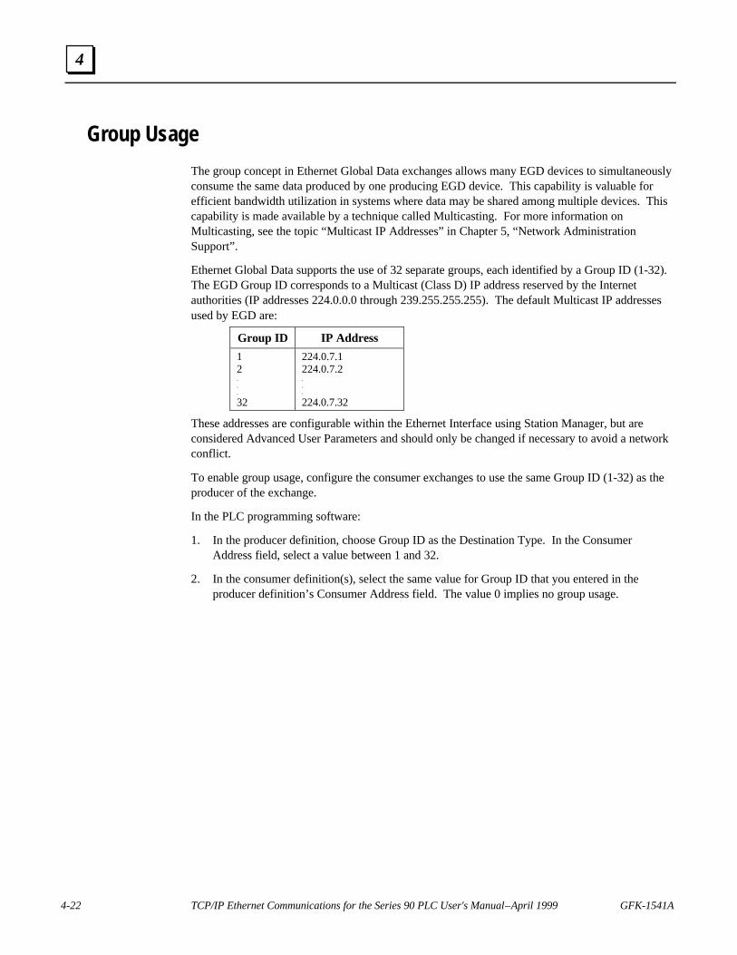
4-22 TCP/IP Ethernet Communications for the Series 90 PLC User's Manual – April 1999 GFK-1541A
4
Group Usage
The group concept in Ethernet Global Data exchanges allows many EGD devices to simultaneouslyconsume the same data produced by one producing EGD device. This capability is valuable forefficient bandwidth utilization in systems where data may be shared among multiple devices. Thiscapability is made available by a technique called Multicasting. For more information onMulticasting, see the topic “Multicast IP Addresses” in Chapter 5, “Network AdministrationSupport”.
Ethernet Global Data supports the use of 32 separate groups, each identified by a Group ID (1-32).The EGD Group ID corresponds to a Multicast (Class D) IP address reserved by the Internetauthorities (IP addresses 224.0.0.0 through 239.255.255.255). The default Multicast IP addressesused by EGD are:
Group ID IP Address
12...
32
224.0.7.1224.0.7.2...
224.0.7.32
These addresses are configurable within the Ethernet Interface using Station Manager, but areconsidered Advanced User Parameters and should only be changed if necessary to avoid a networkconflict.
To enable group usage, configure the consumer exchanges to use the same Group ID (1-32) as theproducer of the exchange.
In the PLC programming software:
1. In the producer definition, choose Group ID as the Destination Type. In the ConsumerAddress field, select a value between 1 and 32.
2. In the consumer definition(s), select the same value for Group ID that you entered in theproducer definition’s Consumer Address field. The value 0 implies no group usage.

GFK-1541A Chapter 4 Ethernet Global Data 4-23
4
Section 4: Exchange Status Word
The Exchange Status word allows an Ethernet Global Data user to obtain the operating status of agiven exchange definition. The PLC will write status codes into the Exchange Status word.
The Exchange Status word is changed upon exchange configuration* and when aproducer/consumer period expires, and the value will be set for the entire period. Therefore, it ispossible for the Exchange Status word to always be set to 1, indicating that at the time the periodexpires, there was no error condition. The user program can monitor for error conditions reportedin the Exchange Status word by setting it to 0 once a non-zero value is written to it.
The first update of the Exchange Status word occurs the first time the producer/consumer periodtimer expires.
NoteThe user-program should also monitor the “LAN Interface OK” Status bit foreach of the Ethernet Interfaces performing EGD. The Exchange Status word isinvalid if the bit is 0. Refer to the topic, “Status Bits”, in Section 4 of Chapter 3,“Programming Communications Requests”, for more information.
The following table shows the error codes that can be written to the Exchange Status word.
Table 4-3. Exchange Status Word Error Codes
Value(Decimal)
P – Produced/C – Consumed Description
0 P/C
No new status event has occurred.Produced: Initial value until the first producer period refresh occurs.
Consumed: The data has not been refreshed since the previousconsumption scan and the consumer timeout has not expired.
1 PNo error currently exists.
The exchange is producing data.
1 CNo error, data consumed.The data has been refreshed on schedule since the previous consumption.
3 C
SNTP error.
The Ethernet Interface in the producer is configured for network timesynchronization, but is not synchronized to an SNTP server. The datahas been refreshed on schedule.
4 P/C
Specification error.Produced: During exchange configuration*, an invalid configurationparameter was received by the Ethernet Interface or an error occurred incommunication with the PLC CPU.
Consumed: Same as Produced, or the size of a received packet for thisexchange definition did not match the expected size.
* Exchange configuration occurs when either 1) Hardware Configuration containing EGD is storedto the PLC, 2) a PLC containing EGD configuration powers up, or 3) an Ethernet Interfaceconfigured for EGD is restarted.

4-24 TCP/IP Ethernet Communications for the Series 90 PLC User's Manual – April 1999 GFK-1541A
4
Table 4-3. Exchange Status Word Error Codes - Continued
Value(Decimal)
P – Produced/C – Consumed Description
6 C
Refresh timeout without data.
The exchange’s timeout period is configured to a non-zero value and thedata has not been refreshed within the timeout period.
7 CData after refresh timeout.
The data has been refreshed since the previous consumption, but was notrefreshed within the timeout period.
10 P/C
IP Layer not currently initialized.
This status can be set during exchange configuration* if the EthernetInterface detects that it cannot currently access a network (cable notconnected, hardware failure, etc.) This is a temporary status which maychange if successful network access becomes possible.
12 P/C
Lack of resource error.
Local resources are not available to establish the exchange. This errorcan only occur during exchange configuration*. The PLC Fault Tableshould be examined to obtain more detail on the specific error.
16 P
Name Resolution in progress.
A local produced exchange definition has specified a name for theconsumer address and the local Ethernet Interface is awaiting a responsefrom a remote name server following exchange configuration*. This is atemporary status that will change when the name resolution completes.If successful, the status will become 0 (No New Data); if unsuccessful,the status will become 4 (Specification Error).
18 P/C
Loss of Ethernet Interface error.
This error can occur if the CPU no longer recognizes the EthernetInterface within the PLC rack. A loss of module PLC Fault Table entrywill also be present. The error can also occur if the module in the givenslot of the PLC rack does not match the module specified in theconfiguration (configuration mismatch).
22 P/CEthernet Interface does not support EGD.
The revision level of the Ethernet Interface does not support global data.
26 P/C
No Response from Ethernet Interface.
Did not respond to establish exchange request. This fault can only occurduring exchange configuration*.
28 P/C
Failed to create an exchange.
An error occurred (other than a resource error, no response or loss ofEthernet Interface) during exchange configuration*. A PLC Fault Tableentry is provided for additional information about the fault.
* Exchange configuration occurs when either 1) Hardware Configuration containing EGD is storedto the PLC, 2) a PLC containing EGD configuration powers up, or 3) an Ethernet Interfaceconfigured for EGD is restarted.

GFK-1541A Chapter 4 Ethernet Global Data 4-25
4
Section 5: Simple Network Time Protocol (SNTP)SNTP is a method of synchronizing the internal clocks in a network's Ethernet Interfaces to anexternal source. In an SNTP system, a computer on the network (called an SNTP server), sends outa periodic timing message to all of the SNTP-capable Ethernet Interfaces on the network, whichkeep their internal clocks synchronized with this common SNTP timing message.
Timestamping EGD Exchanges
Each EGD exchange contains a timestamp that pinpoints when the associated data was transferredfrom the producing PLC's CPU to its Ethernet Interface for transmission over the network. Thetimestamp value is based on a built-in clock in the Ethernet Interface. It sends this value to thePLC CPU, which uses it to timestamp its data exchanges. Its time clock is synchronized to one ofthe following two sources:
n PLC's Time Clock: If the Network Time Sync parameter of the Ethernet Interface is set toNone or DISABLED, the Ethernet Interface’s built-in time clock is synchronized once, atpower-up or restart, to the clock in the local PLC CPU. The disadvantage of this source is thatthe time clocks in the various PLCs on the network are not synchronized, so timestampsproduced by different PLCs cannot be compared accurately.
n SNTP Server's Time Clock: If the Ethernet Interface's Network Time Sync parameter is setto SNTP or ENABLED, the Ethernet Interface’s built-in clock is periodically synchronized tothe clock on the SNTP server. This method has the advantage that all Ethernet Interfacesconfigured to use SNTP will have updated, synchronized timestamps, because they will all besynchronized to the SNTP server's clock. Therefore, accurate timing comparisons betweenexchanged data can be made. For example, if alarm data were sent over the network fromseveral PLCs, it might be advantageous for troubleshooting purposes to know the order inwhich the alarms were generated. Using SNTP, the data's synchronized timestamps could helpyou determine this.
NotesWith SNTP operation, the time value passed from the Ethernet Interface to thePLC CPU is used in the PLC only for timestamping EGD exchanges. It does notaffect the time of the CPU's internal time clock.
SNTP server dates before January 1, 1989 are not supported by the EthernetInterface.
Configuring an Ethernet Interface for SNTP
SNTP operation must be configured for each Ethernet Interface individually. For moreinformation, refer to Chapter 2, Procedure 2, “Configuring the Ethernet Interface”.
Normal SNTP Operation
The Ethernet Interface will synchronize to a remote SNTP time server after receiving two broadcastclock values within a 150-second period. The Station Manager command, SNTP, can be used toview server status information.

4-26 TCP/IP Ethernet Communications for the Series 90 PLC User's Manual – April 1999 GFK-1541A
4
Multiple SNTP Servers
To guard against loss of SNTP timing messages, multiple SNTP time servers can be tracked on anetwork. An Ethernet Interface can maintain timing information from up to four total SNTP timeservers at a time. Each server assigns a stratum number that determines its priority. The messagefrom the server with the lowest stratum number is used by the Ethernet Interface untilcommunication with that server is lost. Then the server with the next lowest stratum numberbecomes the server of choice and the Ethernet Interface synchronizes to it if it receives two of itstiming messages within a 150-second period. A server is considered "lost" if more than 150seconds elapse between timing messages.
The Station Manager command, CHSNTP, can be used to override the Ethernet Interface’sautomatic server selection strategy and identify specific server(s) to be used. For more informationon using the Station Manager, refer to GFK-1186, TCP/IP Ethernet Communications for the Series90 PLC Station Manager Manual.
Loss or Absence of SNTP Timing Signals
If an Ethernet Interface is configured for SNTP, but does not receive two timing messages from anSNTP network time server within a 150 second period, the following will happen:
n A fault entry will be placed in the PLC Fault Table.
n A fault entry will be placed in the Ethernet Interface's exception log. This log can be read byusing the GE Fanuc Station Manager. Details can be found in GFK-1186, TCP/IP EthernetCommunications for the Series 90 PLC Station Manager Manual.
n The Status word within a consumed exchange will indicate new data with a value of 3, insteadof the normal 1 value, indicating that SNTP is selected, but the Ethernet Interface is notsynchronized to an SNTP server. This Status word value can be obtained from the PLCregister configured for the particular exchange.
Note
The SNTP error condition is considered the least important of all possible errorcodes. Therefore, if another error condition exists, its status code will appear inthe Status word instead of the SNTP error code.
Upon loss or absence of synchronization, the Ethernet Interface’s built-in clock will operate asfollows:
n If the Ethernet Interface, after its last power-up/restart cycle, has never received an SNTPserver's timing message, it will continue to use the PLC CPU's local clock value that itreceived at power-up/restart for its time base.
n If the Ethernet Interface has, at some point, been synchronized to an SNTP server but lost itssignal, it will use the most recently received SNTP time message as its time base.
The Ethernet Interface will continue supplying time values to the PLC CPU for timestamping,while it "listens" for SNTP timing messages from the network. If SNTP messages are receivedlater, the Ethernet Interface will then synchronize to them.
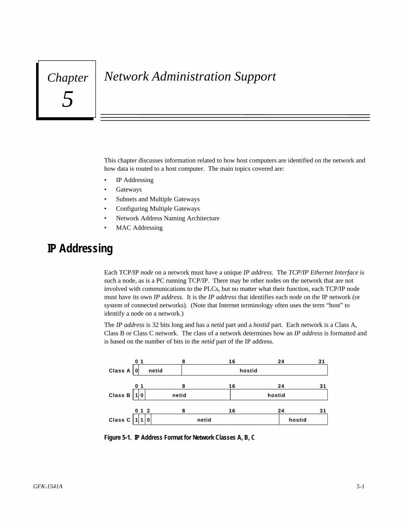
GFK-1541A 5-1
Network Administration Support
This chapter discusses information related to how host computers are identified on the network andhow data is routed to a host computer. The main topics covered are:
• IP Addressing
• Gateways
• Subnets and Multiple Gateways
• Configuring Multiple Gateways
• Network Address Naming Architecture
• MAC Addressing
IP Addressing
Each TCP/IP node on a network must have a unique IP address. The TCP/IP Ethernet Interface issuch a node, as is a PC running TCP/IP. There may be other nodes on the network that are notinvolved with communications to the PLCs, but no matter what their function, each TCP/IP nodemust have its own IP address. It is the IP address that identifies each node on the IP network (orsystem of connected networks). (Note that Internet terminology often uses the term “host” toidentify a node on a network.)
The IP address is 32 bits long and has a netid part and a hostid part. Each network is a Class A,Class B or Class C network. The class of a network determines how an IP address is formatted andis based on the number of bits in the netid part of the IP address.
0 1
Class A 0 netid hostid
8 16 24 31
0 1
Class B 1 netid hostid0
8 16 24 31
0 1 2
Class C 1 netid hostid1 0
8 16 24 31
Figure 5-1. IP Address Format for Network Classes A, B, C
5Chapter
5-2 TCP/IP Ethernet Communications for the Series 90 PLC User's Manual – April 1999 GFK-1541A
5
In general, the netid part is assigned by the Internet authorities and the hostid part is assigned byyour local network administrator. The class of network determines the number of hosts that can besupported. A Class A network can support 224-2 (16,777,214) hosts, Class B, 216-2 (65,534) hosts,and Class C, 28-2 (254) hosts. The minus 2 refers to host numbers reserved for the network itselfand the local broadcast.
Each node on the same physical network must have an IP address of the same class and must havethe same netid. Each node on the same physical network must have a different hostid thus giving ita unique IP address.
IP addresses are written in “dotted-decimal” format as four decimal integers (0-255) separated byperiods where each integer gives the value of one byte of the IP address. For example, the 32-bit IPaddress
00001010 00000000 00000000 00000001
is written as
10.0.0.1
One can determine the class of an IP address by examining the first integer in its dotted-decimal IPaddress and comparing with the range of values in the following table.
Range of first integer Class
0 - 127 A
128 - 191 B
192 - 223 C
224-239 D (Reserved for Multicast Use)
240 - 255 E (Reserved for Experimental Use)
IP Addresses Reserved for Private Networks
RFC 1918 reserves IP addresses in the following ranges to be used for private networks.
10.0.0.0 – 10.255.255.255 (Class A)172.16.0.0 – 172.31.255.255 (Class B)192.168.0.0 – 192.168.255.255 (Class C)
Multicast IP Addresses
Multicast IP Addresses are used in multicasting, a technique that allows delivery of a single packetof data to multiple nodes on the network. Any node that joins a Multicast group will respond to theMulticast IP address assigned to that group. Subsequently, any data sent to that Multicast IPaddress may be received by all nodes which are members of that Multicast group. Multicast (ClassD) IP addresses (224.0.0.0 through 239.255.255.255) are reserved by the Internet authorities formulticasting.
Multicasting is a feature of Ethernet Global Data. For more information on the use of multicastingin Ethernet Global Data, see the topic “Group Usage” in Chapter 4, “Ethernet Global Data”.

GFK-1541A Chapter 5 Network Administration Support 5-3
5
Gateways
Gateways (also known as routers) connect individual physical networks into a system of networks.When a node needs to communicate with a node on another physical network, a gateway transfersthe data between the two networks.
Example: Networks Connected by a GatewayThe following figure shows Gateway G connecting Network 1 with Network 2.
a45405
172.16.0.1
Network 1
172.17.0.1 172.17.0.2
172.17.0.3
Network 2
172.16.0.2
A
B C
G Gateway
Figure 5-2. Connecting Two Networks with a Gateway
When host B with IP address 172.17.0.1 communicates with host C, it knows from C’s IP addressthat C is on the same network. In an Ethernet environment, B can then resolve C’s IP address to aMAC address (via ARP) and communicate with C directly.
When host B communicates with host A, it knows from A’s IP address that A is on anothernetwork (the netids are different). In order to send data to A, B must have the IP address of thegateway connecting the two networks. In this example, the gateway’s IP address on Network 2 is172.17.0.3. This address would be configured in the Ethernet Interface’s module configuration forPLC B as its default gateway address.
Note that the gateway has two IP addresses (172.16.0.2 and 172.17.0.3). The first must be used byhosts on Network 1 and the second must be used by hosts on Network 2. To be usable, a host’sgateway must be addressed using an IP address with a netid matching its own.

5-4 TCP/IP Ethernet Communications for the Series 90 PLC User's Manual – April 1999 GFK-1541A
5
Subnets and Multiple Gateways
For a site requiring a large network (such as a Class A network) the number of entries in therouting tables of a site’s internal gateways could number in the millions if no internal networkstructure is superimposed on the address definition. The solution to this problem is subnetting.
Subnets allow a site’s network administrators to divide a large network into several smallernetworks while still presenting the overall network as one single entity to the outside world. Eachof the site’s interior gateways need only maintain the subnet numbers of other interior gatewaysinstead of every single host on the entire network.
Subnet Addressing and Subnet Masks
Subnet addressing is an extension of the IP address scheme that allows a site to use a single netidfor multiple physical networks. Routing outside the site continues as usual by dividing the IPaddress into a netid and a hostid via the class.
The standard format for the netid bits and hostid bits for an IP address in a Class B network isshown below.
10000000 00000011 00000000 00000001
netid bits hostid bits(binary)
Inside a site the subnet mask is used to re-divide the IP address into a custom netid portion andhostid portion. Consider adding another physical network to Network 2 (a Class B network) in theprevious example (see Figure 5-2). The result is shown in Figure 5-3. Selecting the subnet maskshown below would add two additional netid bits allowing for four physical networks addressed as0, 64, 128, and 192. The added subnet bits are normally taken from the hostid bits adjacent to thenetid and the subnet mask identifies these bits.
11111111 11111111 11000000 00000000 = 255.255.192.0
netid bits hostid bits subnet mask(dotted decimal)(binary)
The bits in the subnet mask correspond one to one with the Internet address. The bits in the maskthat are 1 treat the corresponding bits in the IP address as part of the netid bits. The bits in themask that are 0 treat the corresponding bits as part of the hostid bits.
In effect, two bits of the Class B hostid have been used to extend the netid, creating an extendednetid, or subnetid. Each unique combination of bits in the part of the hostid where subnet mask bitsare 1 specifies a different physical network.

GFK-1541A Chapter 5 Network Administration Support 5-5
5
Example: Network Divided into Two Subnets
The new network configuration dividing Network 2 in Figure 5-2 into Subnets 2.1 and 2.2 isshown below.
172.16.0.1
A
Network 1
172.17.64.1
B
172.17.64.2
C172.17.64.3
G1
(Sub)Network 2.1
172.17.128.1
D
172.17.128.2
E172.17.128.3
G2
(Sub)Network 2.2
172.16.0.2
Gateway
Gateway
172.17.64.4
Figure 5-3. Network Divided into Two Subnets
As shown in Figure 5-3, a second network with Hosts D and E has been added. Gateway G2connects Subnet 2.1 with Subnet 2.2. Hosts D and E will use Gateway G2 to communicate withhosts not on Network 2.2.
Hosts B and C will use Gateways G1 and G2 to communicate with hosts not on Network 2.1.When B is communicating with D, G2 (the configured Gateway for B) will route the data from B toD through Gateway G2.
Host A will use Gateway G1 to communicate with hosts not on Network 1.

5-6 TCP/IP Ethernet Communications for the Series 90 PLC User's Manual – April 1999 GFK-1541A
5
Configuring Multiple Gateways
Multiple Gateways are supported on the Series 90-70 Ethernet Interface (Type 2) and the Series 90-30 CPU364 only.
An Ethernet Interface with the Multiple Gateways feature has the ability to route packets not onlythrough a single default gateway, but also through additional gateways located on the local subnet.
The gateway that is configured in the Ethernet Interface’s hardware configuration (using the PLCprogramming software) is defined as the default gateway. If supported in the Windows-based PLCprogramming software, additional gateways can also be configured to define alternate routes toremote subnets in the Routing tab of the Name Resolution and Routing Table Rack Operation. Onerouting table may be defined for a PLC system, which is made available to all the EthernetInterfaces in that PLC.
Example: Configuring Multiple Gateways
This example is an extension of the example in Subnets and Multiple Gateways (see Figure 5-3).Refer to that example to understand how subnets are created and the subnet mask (255.255.192.0)was determined. This example adds Subnet 2.3.
172.16.0.1
A
Network 1
172.17.64.1
B
172.17.64.2
C172.17.64.3
G1
Local (Sub)Network 2.1
172.17.128.1
D
172.17.128.2
E172.17.128.3
G2
(Sub)Network 2.2
172.16.0.2
Gateway
Gateway
172.17.64.4
172.17.192.1
F
172.17.192.2
H172.17.192.3
G3
(Sub)Network 2.3
Gateway
172.17.64.5
Figure 5-4. Configuring Multiple Gateways
A PLC on Network1, Subnet 2.2, and Subnet 2.3 can talk to a PLC on one of the other networkswithout configuring multiple gateways because there is only one gateway on these networks.Gateway G1 would be configured as the default gateway for PLC A’s Ethernet Interface; GatewayG2 for PLC D’s and E’s Ethernet Interface; and Gateway G3 for PLC F’s and H’s EthernetInterface. The default gateway is configured in the Ethernet Interface’s module configuration.
For Local Subnet 2.1, however, there are three gateways to choose from. The Ethernet Interfacesin PLC B and C must decide where to send data in order for it to arrive at its destination. If youhave not configured these Ethernet Interfaces for multiple gateways and the data destination is noton Local Subnet 2.1, then the only gateway option for each Ethernet Interface is the one youconfigured as the default gateway in module configuration.

GFK-1541A Chapter 5 Network Administration Support 5-7
5
However, if you configure a routing table for PLCs B and C, their data may be forwarded to othergateways. If Gateway G1 has been configured as the default gateway, the routing table could havean entry for Subnet 2.2 via Gateway G2 and Subnet 2.3 via Gateway G3. If the data is not destinedfor either remote Subnet 2.2 or Subnet 2.3, then the data would be routed to Gateway G1, thedefault gateway.
To configure a PLC on Subnet 2.1 to be able to communicate with Network 1, Subnet 2.2, andSubnet 2.3 you need to know the following information.
Address of Gateway (G1) 172.17.64.3 (Default Gateway)Subnet Mask for Subnet 2.1: 255.255.192.0
Address of Gateway (G2) 172.17.64.4Subnet Mask for Subnet 2.2: 255.255.192.0Subnet ID of Subnet 2.2*: 172.17.128.0
Address of Gateway (G3) 172.17.64.5Subnet Mask for Subnet 2.3: 255.255.192.0Subnet ID of Subnet 2.3*: 172.17.192.0
* The subnet ID is derived by ANDing the bits of the subnet mask and an IP address on thedestination subnet.
Module Configuration for the Ethernet Interface in PLC B
The IP address, subnet mask, and default gateway IP address are entered in the Ethernet Interface’smodule configuration.
IP Address: 172.17.64.1
Subnet Mask: 255.255.192.0
Default Gateway IP Address: 172.17.64.3
PLC Routing Table to Configure Multiple Gateways for PLC B and PLC C
The following routing table entries are entered into the PLC’s Routing tab of the Name Resolutionand Routing Tables Rack Operation via the Windows-based PLC programming software (ifsupported).
# Destination Subnet ID Destination Subnet Mask Next Hop IP Address(Gateway IP Address)
Cost
1 172.17.128.0 255.255.192.0 172.17.64.4 1
2 172.17.192.0 255.255.192.0 172.17.64.5 1

5-8 TCP/IP Ethernet Communications for the Series 90 PLC User's Manual – April 1999 GFK-1541A
5
Network Address Naming ArchitectureNaming architecture provides users the ability to refer to their Ethernet Interfaces in terms of asymbolic name rather than a numerical address. This name, commonly referred to as the networkaddress name, can be constructed from the following character set:
a-z A-Z 0-9 ` ~ ! @ # $ % ^ & * ( ) _ + | - = \ { } [ ] : ” ; ’ < > ? . /
Note
The comma is not a supported character for network address names.
Name Assignment
Name assignment associates a symbolic name to an IP address. There are three aspects of nameassignment. The network may employ all or none of the name assignments described herein. Thenext section, Name Resolution, will describe the mechanisms to acquire the address information(IP address) from an assigned symbolic name.
DDP Name Assignment
The first aspect of name assignment deals with the assignment of a network address name to anEthernet Interface. The Ethernet Interface will register this name with DDP (a GE Fanuc namingprotocol), and can be resolved using DDP Name Resolution, as described in a following section.There are two methods to assign a DDP network address name to an Ethernet Interface.
Default DDP Network Address Name
The first method is a default mechanism for the Ethernet Interface to assign itself a network addressname. If the Ethernet Interface has no source for a network address name at startup, it will generatea name in the form:
“cmm321_xxxxxx” for the Series 90-30 Ethernet Interface“cpu364_xxxxxx” for the Series 90-30 CPU364 Embedded Ethernet Interface“cmm742_xxxxxx” for the Series 90-70 Ethernet Interface (Type 2)
where xxxxxx is the ASCII representation of the six rightmost hexadecimal digits of the MACaddress used by this module.
This default mechanism will be used whenever no name is assigned to the Ethernet Interface in themodule configuration using the PLC programming software (if supported), as described in thefollowing section.
Assigned DDP Network Address Name
The second method is assignment of a network address name to the Ethernet Interface by the PLCprogramming software (if supported). The network address name is assigned in moduleconfiguration as the Adapter Name for the Ethernet Interface and stored to the PLC. This assignedDDP network address name will override the default DDP network address name. See Online Helpin the PLC programmer software for instructions. (For the Series 90-30 Ethernet Interface, anetwork address name may only be assigned with the Station Manager command, CHMYNAME.

GFK-1541A Chapter 5 Network Administration Support 5-9
5
This command is documented in GFK-1186, TCP/IP Ethernet Communications for the Series 90PLC Station Manager Manual.)
Local Name Table Name Assignment
The second aspect involves building a name table that contains a mapping of symbolic names toassociated IP addresses. A name assigned in this table is also known as an alias. A networkaddress name assigned in the local name table can be resolved by Local Name Table NameResolution, as described in a following section. This table may be created as follows:
n For the Series 90-70 Ethernet Interface (Type 2) and Series 90-30 CPU364, a name tablecan only be created using the Windows-based PLC programming software (if supported).Refer to the topic, “Setting Aliases for Remote Network Adapters”, in Section 3 of Chapter 4,“Ethernet Global Data”.
n For the Series 90-30 Ethernet Interface, a name table can only be added, edited, and deletedwith the Station Manager command, CHNAMETBL. This command is documented in GFK-1186, TCP/IP Ethernet Communications for the Series 90 PLC Station Manager Manual.
DNS Name Assignment
The third aspect involves connecting and configuring a DNS (Domain Name System) name serverto the network. This DNS name server contains a database of name assignments and thecorresponding address information (IP address) for each of these names. This DNS name servercan be queried to acquire the IP address of a symbolic name known to that DNS name server. Anetwork address name assigned in a DNS name server can be resolved using DNS NameResolution, as described in a following section. Please ask your network administrator for moreinformation about the availability of a DNS name server on your network.
Name Resolution
Name resolution involves resolving a symbolic name (network address name) to its necessaryaddress information required for communication. Without name resolution functionality, a user isrequired to know this addressing information (that is, IP address) to establish communication witha remote device. Name resolution provides users a means to also use a symbolic name to reach theremote destination.
For the purposes of this description, the client is the device which needs to resolve a symbolicname. This symbolic name represents the IP address of the server. Possible clients include a userof the Host Communications Drivers and users of the client capability on the Ethernet Interface (forexample, Channel API). Possible servers include the Ethernet Interface (for example, SRTPServer) and the Host Communications Drivers (for example, unsolicited messages).
Name resolution of a symbolic name into an IP address follows a strict precedence rule as follows:(The precedence order is configurable as an advanced parameter using the Station Manager.)
1. Local Name Table
2. DDP
3. DNS

5-10 TCP/IP Ethernet Communications for the Series 90 PLC User's Manual – April 1999 GFK-1541A
5
Each of these is described in more detail in the following sections.
Local Name Table Name Resolution
Local name table name resolution involves a simple table lookup to see if a mapping of thesymbolic name to its IP address information exists. Configuration of this table is described in thetopic “Local Name Table Name Assignment” earlier in this chapter.
DDP Name Resolution
If local name table name resolution fails, DDP (a GE Fanuc naming protocol) is used todynamically resolve the symbolic name. DDP name resolution involves the client nodebroadcasting a message on the network asking if any node recognizes the symbolic name. If a nodedoes recognize the name, it responds and supplies the associated IP address. The client can thenproceed with communication directly to that IP address. DDP uses broadcast traffic to performname resolution. Certain routing configurations do not support routing of broadcast traffic, whichimplies that DDP name resolution will not work over such routers.
DNS Name Resolution
If both local name table and DDP name resolution fail, DNS is then attempted. This protocol is anindustry standard for resolving symbolic names to IP addresses with the assistance of a remoteDNS name server. The format of DNS usage is defined by RFCs 1034 and 1035. A separate DNSname server on the network is required for DNS operation.
To use DNS name resolution, the IP address of the remote DNS name server must be supplied tothe Ethernet Interface in the PLC configuration. The symbolic name must be defined at the DNSname server.
Name Usage
Various areas of the PLC system support the use of this naming architecture. They can be brokeninto three categories: Channel API commands, Ethernet Global Data (EGD), and Station Managercommands.
Some Channel API commands allow the use of symbolic names in the remote node addressingfields of the COMMREQ Function Block. This is described in further detail in Chapter 3,“Programming Communications Requests”.
In the configuration of an EGD exchange, the local Ethernet Interface that is responsible forproducing/consuming the EGD is identified by its network address name (adapter name). Also, inthe configuration of a produced exchange, the consumer address may be identified as a symbolicname. For more information, refer to Chapter 4, “Ethernet Global Data”.
The following Station Manager commands pertain to symbolic names: MYNAME, NAMETBL,BROWSEDDP, PING, REM, and RESOLVE. These commands are described in detail inGFK-1186, TCP/IP Ethernet Communications for the Series 90 PLC Station Manager Manual.

GFK-1541A Chapter 5 Network Administration Support 5-11
5
MAC Addresses
Note
It is highly recommended that you use the unique default MAC supplied withinthe Ethernet Interface. However, you may override that default with a MACaddress of your own choosing with the Station Manager CHPARM MACADDRcommand (See GFK-1186, TCP/IP Ethernet Communications for the Series 90PLC Station Manager Manual.)
The MAC address is a 48-bit binary number that identifies the station on the physical network. TheMAC address is typically expressed as a 12-digit hexadecimal number. A typical MAC address isrepresented as follows:
Byte 1 2 3 4 5 6 ________ _________ _________ _________ _________ _________Hex 0 8 0 0 1 9 0 1 5 3 1 2Binary 0000 1000 0000 0000 0001 1001 0000 0001 0101 0011 0001 0010
Another characteristic that is important, especially for multi-vendor networks, is the order ofaddress-bit transmission on the physical medium. MAC addresses are transmitted in ascendingbyte order, with the least significant bit of each byte transmitted first.
The example above is shown including bit transmission order as follows:
Byte 1 2 3 4 5 6 ________ _________ _________ _________ _________ _________ Hex 0 8 0 0 1 9 0 1 5 3 1 2 Binary 0000 1000 0000 0000 0001 1001 0000 0001 0101 0011 0001 0010Bit Order 8765 4321 ...9 | | MSB of the MAC LSB of the MAC address-first bit transmitted address-last bit transmitted
If you assign your own MAC addresses, there are 2 bits of the 48-bit address that you must setaccording to the instructions that follow:
• Bit 1 in Byte 1 must always be a 0 to indicate an individual station rather than a Group address.
• Bit 2 in Byte 1 must be a 1 to indicate that the address is locally administered. (In the typicaldefault MAC address shown above, bit 2 in Byte 1 is a 0 indicating that it is a globallyadministered address).
• All other bits can be set as desired as long as all stations on the network have unique addresses.
An example of a locally administered MAC address is shown below.
Byte 1 2 3 4 5 6 ________ _________ _________ _________ _________ _________ Hex 0 2 0 0 0 0 0 0 0 1 0 0 Binary 0000 0010 0000 0000 0000 0000 0000 0000 0000 0001 0000 0000Bit Order 8765 4321 ...9 | | MSB of the LSB of the MAC address-first bit transmitted MAC address-last bit transmitted
If you must change the Station MAC address, check with the person administering your network tomake sure that you select an address that fits into your local administration scheme.

GFK-1541A 6-1
Troubleshooting
This chapter is a guide to troubleshooting and problem isolation for the Series 90-30 EthernetInterface, the Series 90-30 CPU364, and the Series 90-70 Ethernet Interface (Type 2). This chapterincludes the sections listed below:
n Diagnostic Tools Available for Troubleshootingn What to do if you Cannot Solve the Problemn PLC Fault Table
Diagnostic Tools Available for Troubleshooting There are several tools to assist you in diagnosing problems with the Series 90 Ethernet Interfaceand the network.
n Use the Ethernet Interface LEDs to troubleshoot a problem on power-up of the EthernetInterface and for an immediate visual summary of the operational state of the Interface. Referto Chapter 2, “Installation”, for more information.
n Use the Series 90 PLC Fault Table to troubleshoot a problem once the Interface is running. Itprovides a record of exceptions logged by the PLC, the Ethernet Interface, and other Series 90modules. The PLC Fault Table may be accessed through the PLC programming software.Look in the PLC Fault Table for a logged fault, then refer to the PLC Fault Table section inthis chapter for instructions on what action to take.
n Use the Status Data to troubleshoot ladder programs containing COMMREQ functions thatinitiate communications. The status data consists primarily of the Status bits and theCommunications Status words. Refer to Chapter 3, “Programming CommunicationsRequests”, for more information.
n For Ethernet Global Data operation, Exchange Status words can be used to troubleshootexchange operations. Refer to Chapter 4, “Ethernet Global Data”, for more information.
n Use the Station Manager software to troubleshoot a problem with the Ethernet Interface, withthe network, with PLC backplane communication, or with your application. The LOG,TALLY, EXS, CHANNEL and STAT Station Manager commands are especially useful.
o The LOG command provides a complete record of exceptions occurring with the networkand Interface.
o The TALLY command provides statistics about operation and performance of the networkand Interface.
o The EXS command provides information about COMMREQs.
6Chapter

6-2 TCP/IP Ethernet Communications for the Series 90 PLC User's Manual – April 1999 GFK-1541A
6
o The CHANNEL command displays detailed information about a specified communicationchannel.
o The STAT command provides the current status on the operation of the Interface.
Refer to GFK-1186, TCP/IP Ethernet Communications for the Series 90 PLC Station ManagerManual, for information on how to access and use the Station Manager software.
What to do if you Cannot Solve the ProblemIf, after using the troubleshooting guide, you still cannot solve your problem, call GE FanucAutomation - NA. Please have the following information available when you call.
n The Name and Catalog Number marked on the product.
n Description of symptoms of problem. Depending on the problem, you may also be asked forthe following information:
o The ladder logic application program and the PLC sweep time at the time the problemoccurred.
o A listing of the configuration parameters for the Ethernet Interface that failed.
o A description of the network configuration. This should include the number of PLCs andhost computers accessing the network, the type of network cable used (e.g. twisted pair,fiber optic, etc.), length of network cable, and the number and manufacturer oftransceivers, hubs, and network switches used.
PLC Fault TableThe PLC Fault Table can be accessed in PLC programming software. If you are experiencing aproblem with the Ethernet Interface, check the PLC Fault Table for a fault message, then refer toTable 6-1 in this chapter for instructions on what to do about the problem.
To access the details of a PLC Fault Table entry:
n For Windows-based PLC programming software, double-click the Fault Table entry and thedetails are displayed as “fault extra data”. Refer to Online Help in the PLC programmingsoftware for more information.
n For Logicmaster 90 programming software, select the Fault Table entry and press <CTRL-F>to view the fault details. The “fault extra data” are the long strings of digits on the right half ofthe message line. Refer to GFK-0265, Logicmaster 90-70 Programming Software ReferenceManual or GFK-0467, Series 90-30/20/Micro Programming Software Reference Manual, formore information.
An example of the fault extra data is shown below:
For Ethernet Interfaces the leftmost 14 digits of fault extra data (underlined in the example above)show the corresponding log Events (2 digits) and Entries 2, 3, and 4 (in that order, 4 digits each).The example above is reporting an Event 16, Entry 2=6, Entry 3=3, and Entry 4=5.
160006000300050000000000000000000000000000000000

GFK-1541A Chapter 6 Troubleshooting 6-3
6
This information can be used to refer directly to detailed fault descriptions included in the Logevent table under the LOG command in GFK-1186, TCP/IP Ethernet Communications for theSeries 90 PLC Station Manager Manual.

6-4 TCP/IP Ethernet Communications for the Series 90 PLC User's Manual – April 1999 GFK-1541A
6
Table 6-1. PLC Fault Table Descriptions
PLC Fault User Action
Backplane communications with PLC fault;lost request
User Action: Check to make sure you are not sendingCOMMREQs faster than the Ethernet Interface canprocess them. If problem persists, contact GE FanucAutomation - NA.
Bad local application request; discardedrequest
User Action: Check for valid COMMREQ commandcode. If problem persists, contact GE Fanuc Automation -NA.
Bad remote application request; discardedrequest
User Action: Try to validate the operation of the remotenode. If problem persists, contact GE Fanuc Automation -NA.
Can’t locate remote node; discarded request Error reported when message received where IP/MACaddress cannot be resolved. Error may indicate thatremote host is not operational on the network.User Action: Check that remote host is operational onnetwork and its addresses are correct.
Comm_req - Bad task ID programmed Message from PLC for unknown Ethernet Interface task.User Action: Check COMMREQ function block.
Comm_req - Wait mode not allowed User Action: Check COMMREQ to make sure sent in no-wait mode.
Config’d gateway addr bad; can’t talk off localnet
Error in configuration. Verify IP address, SubnetworkMask, and default Gateway IP address arecorrect.
Connection to remote node failed; resumingwithout it
Underlying communications software detects errortransferring data; resuming. If persistent error,check connection to LAN and operation of remote node.
LAN controller fault; restart LAN I/F User Action: HW fault, perform power cycle. If problempersists, contact GE Fanuc Automation - NA.
LAN controller Tx underflow; attemptrecovery
Internal system error. User Action: If problempersists, contact GE Fanuc Automation - NA.
LAN controller underrun/overrun; resuming Internal system error. User Action: If problempersists, contact GE Fanuc Automation - NA.
LAN data memory exhausted - check parms;resuming
The Ethernet Interface does not have free memoryto process communications. User Action: Ifproblem persists, contact GE Fanuc Automation - NA.
LAN duplicate MAC Address; resuming A frame was received in which the source MACAddress was the same as this station’s MAC Address. Allstations on a network must have a unique MAC address.Immediately isolate the offending station; it may benecessary to turn it off or disconnect it from the network.This station remains Online unless you intervene to take itOffline.
LAN controller fuse blown; off network (Series 90-70 Ethernet Interface (Type 2) and Series 90-30 CPU364) The network port fuse is blown; port isunusable. Isolate and correct the cause of the problem,then replace the fuse or the Ethernet Interface. Refer toChapter 2, “Installing the Ethernet Interface”, for fusetype and replacement procedures.

GFK-1541A Chapter 6 Troubleshooting 6-5
6
Table 6-1. PLC Fault Table Descriptions (Continued)
PLC Fault User Action
LAN I/F can’t init - check parms; running softSw utl
Internal system error. User Action: If problempersists, contact GE Fanuc Automation - NA.
LAN I/F capacity exceeded; discarded request Verify that connection limits are not being exceeded.
LAN interface hardware failure; switched offnetwork
User Action: Replace Ethernet Interface.
LAN network problem exists; performancedegraded
Excessive backlog of transmission requests due toexcessive traffic on the network. For a sustained periodthe MAC was unable to send frames as quickly asrequested. User Action: If problem persists, contact GEFanuc Automation - NA.
LAN severe network problem; attemptingrecovery
External condition prevented transmission of frame inspecified timeframe. Could be busy network or networkproblem. User Action: Check transceiver to make sure itis securely attached to the network. Check forunterminated trunk cable.
LAN system-software fault; abortedconnection resuming
Internal system error. User Action: If problempersists, contact GE Fanuc Automation - NA.
LAN system-software fault; restarted LAN I/F Internal system error. User Action: If problempersists, contact GE Fanuc Automation - NA.
LAN system-software fault; resuming Internal system error. User Action: If problempersists, contact GE Fanuc Automation - NA.
LAN transceiver fault; OFF network untilfixed
Transceiver or transceiver cable failed or becamedisconnected. User Action: Reattach the cable or replacethe transceiver cable. Check SQE test switch if present ontransceiver.
Local request to send was rejected; discardedrequest
Internal error. Check that the Ethernet Interface is online.User Action: If problem persists, contact GE FanucAutomation - NA.
Memory backup fault; may lose config/log onrestart
Internal error accessing FLASH device.User Action: If problem persists, contact GE FanucAutomation - NA. Replace Ethernet Interface.
Module software corrupted; requesting reload Catastrophic internal system error. Contact GE FanucAutomation - NA.
Module state doesn’t permit Comm_Req;discarded
COMMREQ received when Ethernet Interface cannotprocess COMMREQ. User Action: Make sure EthernetInterface is configured and online.
Unsupported feature in configuration PLC firmware does not support Ethernet communicationssoftware or attempt has been made to configure a featurenot supported by the Ethernet Interface. User Action:Check CPU and Ethernet Interface revisions, orderupgrade kit for CPU and/or Ethernet Interface.
Network Adapter does not support EthernetGlobal Data
Ethernet Interface does not support Ethernet Global Dataoperation. User Action: Check Ethernet Interfacerevision; order upgrade kit for Ethernet Interface.

GFK-1541A A-1
Glossary
In communications, a number of special terms are used, and many of these terms are referenced byacronyms.
This appendix contains a concise, alphabetized listing of conventional communications terms and(where applicable) their associated acronyms. Most of these terms (but not necessarily all) are usedin this manual.
Commonly Used Acronyms and Abbreviations
This is a listing of acronyms, and their derivation, that are commonly used throughout this manual.
API Application Program InterfaceARP Address Resolution ProtocolASCII American National Standard Code for Information InterchangeAUI Attachment Unit InterfaceAAUI Apple Attachment Unit InterfaceBOOTP Boot Strap ProtocolBPS Bits Per SecondCCU Communication Configuration UtilityCPU Central Processing UnitCRS COMMREQ StatusCSMA/CD Carrier Sense Multiple Access with Collision DetectionDCE Data Communications EquipmentDCS Detailed Channel StatusDDP Distributed Directory ProtocolDIB Directory Information BaseDHCP Dynamic Host Configuration ProtocolDNS Domain Name SystemDOS Disk Operating SystemDTE Data Terminal EquipmentEGD Ethernet Global DataGSM GEnet System ManagerH HexadecimalHEX HexadecimalI/O Input/OutputICMP Internet Control Message ProtocolIEEE Institute of Electrical and Electronics EngineersIGMP Internet Group Management ProtocolIP Internet ProtocolISO International Organization for StandardizationK 1024KB Kilobyte (1024 bytes)
AAppendix

A-2 TCP/IP Ethernet Communications for the Series 90 PLC User's Manual – April 1999 GFK-1541A
A
LAN Local Area NetworkLED Light Emitting DiodeLIS LAN Interface StatusLLC Logical Link ControlLSAP Link Layer Service Access PointMAC Medium Access ControlMB Megabyte (1,048,576 bytes)PC Personal Computer, IBM compatiblePDU Protocol Data UnitPLC Programmable Logic ControllerRAM Random Access MemoryRFC Request for CommentsSNTP Simple Network Time ProtocolSQE Signal Quality ErrorSRTP Service Request Transfer ProtocolTCP Transmission Control ProtocolTCP/IP Transmission Control Protocol/Internet ProtocolUDP User Datagram Protocol
Glossary of TermsAdapter Name A name assigned to locally identify a module (e.g., an Ethernet Interface) in the
local station. (See also Network Address Name.)
Address Administration The assignment of LAN addresses locally or on a universal basis.
Address Field The part of a Protocol Data Unit (PDU) that contains an address.
Address Resolution Protocol (ARP) The Internet Protocol that binds dynamically a highlevelInternet Address to a lowlevel physical hardware address such as a MAC address.
Apple Attachment Unit Interface (AAUI) A lower power, smaller connector adaptation of theIEEE 802.3 AUI.
ASCII Code The American Standard Code for Information Interchange is an information codestandard by which digits, letters, symbols and control characters can be encoded as numbers.
Attachment Unit Interface (AUI) In a network node on a Local Area Network, the interfacebetween the medium attachment unit (MAU) and the data terminal equipment. Often called“transceiver cable”.
AUI/AAUI Port A connector on the network interface.
AUI/AAUI Cable The cable between the AUI/AAUI port and the transceiver (some transceiversplug directly into the AUI/AAUI port, thus requiring no separate cable).
Bit Contraction of Binary Digit. The smallest unit of memory. Can be used to store one piece ofinformation that has only two possible states or values (e.g., One/Zero, On/Off, Yes/No). Datathat requires more than two states or values (e.g., numerical values) requires multiple bits (SeeWord).
BOOTP BOOTP is a bootstrap protocol that allows a TCP/IP network node (such as a Series 90PLC with Ethernet Interface) to discover its own IP address and other configurationinformation. This information is supplied from a BOOTP Server device on the network.
Bridge A functional unit that interconnects two Local Area Networks (LANs) that use the samelogical link control protocol, but may use different medium access control protocols. A bridgeconnects network nodes at the Data Link Layer, ISO layer 2.

GFK-1541A Appendix A Glossary A-3
A
Broadcast Sending of a frame that is intended to be accepted by all other nodes on the same LocalArea Network.
Broadcast Address A LAN group address that identifies the set of all nodes on a Local AreaNetwork.
Bus Network A Local Area Network in which there is only one path between any two networknodes and in which data transmitted by any node is available to all other nodes connected tothe same transmission medium. NOTE: A bus network may be linear, star, or tree topology.
Byte A group of bits, typically 8 bits, operated on as a single unit. A single ASCII charactertypically occupies one byte. (See Octet).
Carrier Sense In a Local Area Network, an ongoing activity of a network node to detect whetheranother node is transmitting.
Carrier Sense Multiple Access with Collision Detection (CSMA/CD) A bus network in whichthe medium access control protocol requires carrier sense and in which exception conditionscaused by collisions are resolved by retransmission.
Channel An association in a client PLC between the PLC application program and an EthernetInterface in that same PLC. The ladder program initiates the channel when it issues aCommunications Request (COMMREQ) to its local Ethernet Interface. In turn, this localEthernet Interface initiates a connection to a remote server and then makes periodic datatransfers between the client and server PLCs. (See also Connection.)
Channel Status Bits The Channel Status bits comprise bits 17-80 (64 bits) of the status indicationarea. These bits consist of an error bit and a data transfer bit for each of the channels that canbe established (32 channels for the Series 90-70 Ethernet Interface, 16 channels for the Series90-30 Ethernet Interfaces). Status bits for unused channels are always set to zero.
Client A node that requests network services from a server. A client PLC initiates acommunications request. (See also Server.)
Collision A condition that results from concurrent transmissions by two or more nodes on thetransmission medium.
Collision Domain A single CSMA/CD network. If two or more nodes are within the samecollision domain and both transmit at the same time, a collision will occur. Nodes separatedby a repeater are within the same collision domain. Nodes separated by a bridge are withindifferent collision domains.
Command Dictionary Provides an alphabetical listing of the LAN Interface commands.
Command Field That part of a protocol data unit (PDU) that contains commands, as opposed tothe address field and information field.
COMMREQ Function Block The COMMREQ Function Block is the Series 90 PLC ladderinstruction used to initiate a communications request.
COMMREQ Status Word (CRS Word) The 16-bit CRS word receives the initial status of theSeries 90 PLC communication request from the Series 90 module to which the communicationrequest was addressed. The location of the CRS word is assigned, for each COMMREQfunction, in the common area of the COMMREQ Command Block.
Communication Configuration Utility A utility used by the Windows-based PLC programmingsoftware and the Host Communications Toolkit to configure local communication parametersfor connecting to PLCs.

A-4 TCP/IP Ethernet Communications for the Series 90 PLC User's Manual – April 1999 GFK-1541A
A
Communications Window A part of the PLC scan that provides an opportunity for the LANInterface to read and write PLC memory. The window is executed automatically once per PLCscan.
Connection An association between a client and server on a network, used to reliably transferdata between the two. Here, usually refers to a TCP or an SRTP connection, where the client,server, or both are PLCs. (See also Channel.)
Consumer In Ethernet Global Data, a device (such as a PLC) that receives a data exchange froma Producer. (See also Producer, Exchange.)
CRS Word See COMMREQ Status Word.
CSMA/CD See Carrier Sense Multiple Access with Collision Detection.
Data Communications Equipment (DCE) Examples: Modems and transceivers. Distinct fromDTE, Data Terminal Equipment.
Data Link Layer In Open Systems Interconnection architecture, the layer (Layer 2) that providesservices to transfer data over a physical link between open systems. Consists of the LLC andMAC sublayers.
Data Terminal Equipment Examples: computers, terminals, printers. Distinct from DCE, DataCommunications Equipment.
DCS Words See Detailed Channel Status Words.
Detailed Channel Status Words Two status words containing detailed information on a singleSeries 90 channel. The DCS words are retrieved using the Retrieve Detailed Channel StatusCommand.
Directory Information Base (DIB) A collection of information used for directory services (likename resolution). In this document DIB refers to the DDP database which is actuallydistributed among all DDP devices instead of in a single name server. (See also DistributedDirectory Protocol (DDP)).
Distributed Directory Protocol (DDP) The GE Fanuc proprietary protocol used to providedistributed name service on a TCP/IP Ethernet network. The distributed nature of DDP meansthat there is no centralized name server.
Domain Name System (DNS) The predominant name service protocol used by the Internet.DNS is primarily used to resolve a name into an IP address.
Dotted-Decimal The notation for IP, gateway, and name server addresses as well as the subnetmask. It consists of 4 decimal numbers (0-255) separated by periods. Example IP address:10.0.0.1
Dynamic Host Configuration Protocol (DHCP) A superset of the BOOTP protocol (SeeBOOTP.)
Ethernet Global Data (EGD) A proprietary protocol that provides efficient connectionlessperiodic data transfer over an Ethernet network. Operates over the UDP protocol.
Ethernet Interface The general term used in this manual to identify the GE Fanuc hardwaremodule, with or without software, that connects a PLC (or CNC) to a network. It may alsoappear in the shortened form, “Interface”. (See also LAN Interface.)

GFK-1541A Appendix A Glossary A-5
A
Exchange In Ethernet Global Data, a set of variables or memory locations within the PLC or otherdevice to be transferred from a Producer to a Consumer. (See also Producer, Consumer.)
Exchange ID In Ethernet Global Data, a numerical value assigned by the user to identify aspecific data exchange to be sent by the producing device. (See also Producer, Consumer,Exchange.)
Exchange Status Word The 16-bit Exchange Status word continuously indicates the status of anEthernet Global Data exchange.
Extended Netid See Subnet Id.
Flash Memory A type of read-only memory that can be erased and reprogrammed under localsoftware control. It is used to store data that must be preserved when power is off.
Frame A data structure that consists of fields, predetermined by a protocol, for the transmissionof user data and control data.
Gateway A special purpose, dedicated computer that attaches to two or more (sub)networks androutes packets from one to the other. In particular, an Internet gateway routes IP datagramsamong the networks to which it connects. Gateways route packets to other gateways until theycan be delivered to the final destination directly across the physical (sub)network. (Alsosometimes referred to as a router.) A gateway or router connects network nodes at theNetwork Layer, ISO layer 3.
Global Address Administration Address administration in which all LAN individual addressesare unique within the same or other Local Area Networks. (See also Local AddressAdministration.)
Global Data See Ethernet Global Data.
Group Address An IP multicast address that identifies a group of network nodes on a Local AreaNetwork.
Host A computer or workstation that communicates with stations such as PLCs or CNCs across anetwork, especially one that performs supervisory or control functions. Note that this sameterm is widely used in TCP/IP literature to refer to any network node that can be a source ordestination for network messages. (See also Hostid.)
Host Group A group IP address used to receive multicast IP messages from the network. HostGroup addresses must be valid Class D (multicast) IP addresses.
Hostid The hostid is the part of the IP address identifying the host on the network. (See alsoNetid.)
Hub See Repeater
IEEE 802 The IEEE 802 LAN series of standards are as follows:
IEEE 802 Overview and Architecture.
IEEE 802.2 The Logical Link Control (LLC) sublayer of OSI Data Link Layer common above allIEEE 802 Medium Access Control (MAC) sublayers.
IEEE 802.3 CSMA/CD (Ethernet) MAC and Physical Layer standard.
IEEE 802.4 Token Bus (MAP LANs) MAC and Physical Layer standard.
IEEE 802.5 Token Ring (IBM) MAC and Physical Layer standard.
Information Field That part of a protocol data unit (PDU) that contains data, as opposed to theaddress field and command field.

A-6 TCP/IP Ethernet Communications for the Series 90 PLC User's Manual – April 1999 GFK-1541A
A
Initiating Station The station from which an instance of communication (a transaction)originates. Also referred to as “client”.
Interface Shortened form for “Ethernet Interface”. The general term used in this manual toidentify the GE Fanuc hardware module, with or without software, that connects a PLC (orCNC) to a network. (See also LAN Interface.)
Internet Any collection of networks and gateways that use the TCP/IP protocols and function as asingle, cooperative virtual network, specifically, the worldwide Connected Internet
Internet Address A unique Internet address identifies each node on an IP network (or system ofconnected networks). The Internet address is assigned to the node by the user. (Also knownas an IP address.) (See also Physical Address.)
Internet Control Message Protocol (ICMP) The Internet standard protocol that handles errorand control messages.
Internet Group Management Protocol (IGMP) The Internet standard protocol that handlesmulticast group management messages.
Internet Protocol (IP) The Internet standard protocol that defines the Internet datagram andprovides the basis for the Internet packet delivery service. (See also Transmission ControlProtocol (TCP).)
Inter Repeater Link (IRL) A mechanism for interconnecting two and only two repeater units. TheInter Repeater Link acts at the Physical Layer, ISO layer 1.
IP Address See Internet Address.
Jabber A transmission by a network node beyond the time interval allowed by the protocol.
LAN Interface A term used in this manual to identify the GE Fanuc hardware module, with orwithout software, that connects a PLC or CNC to a network.
LAN Interface Status Bits (LIS Bits) The LIS bits comprise bits 1-16 of an 80-bit status bit area.The location of this 80-bit status area is assigned using the PLC programming software in the“Status Address” field. The LIS bits contain information on the status of the Local AreaNetwork (LAN) and the Ethernet Interface itself.
Linear Topology A network topology in which nodes are each connected at a point along acommon continuous cable which has no loops and only two endpoints.
Link Service Access Point (LSAP) A Data Link layer SAP. A single byte that identifies therouting of data received by the network node.
LIS Bits See LAN Interface Status Bits.
Local Address Administration Address administration in which all LAN individual addressesare unique within the same Local Area Network. (See also, Global Address Administration.)
Local Area Network (LAN) A computer network located on a user’s premises within a limitedgeographical area.
Local Broadcast A transmission which is directed to every available receiver in the local IPsubnet of the transmitter. A local broadcast is never routed to LANs outside of the local IPsubnet.
Local Station The station at your immediate location, i.e., “here”. (See also Remote Station.)
Log Events Events recorded in the system exception log for the LAN Interface. The maximumnumber of events in the exception log is 16.

GFK-1541A Appendix A Glossary A-7
A
Logical Link Control (LLC) Protocol In a Local Area Network, the protocol that governs theexchange of frames between network nodes independently of how the transmission medium isshared.
MAC Address The Medium Access Control (MAC) address is a 12–digit hexadecimal numberthat identifies a node on a local network. Each Ethernet Interface has its own unique MACaddress.
Medium Access Control (MAC) In a Local Area Network (LAN), the part of the protocol thatgoverns write (or transmission) access to the transmission medium independently of thephysical characteristics of the medium, but taking into account the topological aspects of thenetwork, in order to enable the exchange of data between network nodes. The MAC layer isthe lower sublayer of the Data Link Layer, ISO layer 2.
Medium Attachment Unit (MAU) In a network node on a Local Area Network (LAN), a deviceused to couple the data terminal equipment (DTE) to the transmission medium. Often called“transceiver”. The MAU may be built into the DTE or it may be a separate unit that attachesto the DTE through an AUI.
Multicast The transmission scheme in which a limited group of multiple receivers are theintended target of a transmission.
Multicast Address A LAN group address that identifies a subset of the network nodes on a LocalArea Network.
Multiple Gateway Routing The capability of an Ethernet Interface to route a received message toeither the default gateway or one of additional gateways configured at the Ethernet Interface.
Name A character string used to identify and address something.
Name Resolution A “hidden” process that permits application programs to address networknodes using a symbolic name (Network Address Name) in lieu of a numeric IP address.
Netid The netid is the part of the IP address identifying the network on which the node resides.(See also Hostid.)
Network An arrangement of nodes and interconnecting branches.
Network Adapter The device, such as the Ethernet Interface, providing communications servicesfor a particular network.
Network Address Name A character string that is used in lieu of an IP address. The client and/orserver device uses Name Resolution to resolve this symbolic name into the actual IP address.This name represents the address on the network of a particular network adapter. Also referredto as “Adapter Name”.
Node The physical module that connects a node to the network. The Ethernet Interface is anexample of a node. It connects a station (PLC or CNC) to a network (Factory LAN). A stationmay contain more than one Ethernet Interface and therefore contains more than one node.
Octet A group of 8 bits operated on as a single unit. (See also Byte.)
One-Way Propagation Time See Transmission Path Delay.
Path The sequence of segments and repeaters providing the connectivity between two DTEs. InCSMA/CD networks, there is one and only one path between any two DTEs.
Peer Another entity at the same level (layer) in the communication hierarchy.
Peer-Peer Communication between nodes at the same level or layer in the hierarchy.

A-8 TCP/IP Ethernet Communications for the Series 90 PLC User's Manual – April 1999 GFK-1541A
A
Physical Address The unique physical layer address associated with a particular node on theLocal Area Network (LAN). Ethernet physical addresses are typically assigned by themanufacturer. (See for comparison, Internet Address.)
Producer In Ethernet Global Data, a device (such as a PLC) that periodically produces newsamples of data (data exchange). (See also Consumer, Exchange.)
Producer ID In Ethernet Global Data, a dotted-decimal number used to uniquely identify aProducer device (such as an entire PLC system) on the network. (See also Producer,Consumer, and Exchange.)
Protocol A set of rules for exchanging messages between two communicating processes.
Protocol Data Unit (PDU) Information that is delivered as a unit between peer entities of a LocalArea Network (LAN) and that contains control information, address information, and maycontain data.
Remote Station A station located elsewhere on the network. (See also Local Station.)
Repeater In a Local Area Network (LAN), a device that amplifies and regenerates signals toextend the range of transmission between network nodes or to interconnect two or moresegments. A repeater connects network nodes at the Physical Layer, ISO layer 1.
Responding Station A station which generates a message in response to a command that wasdirected to the station.
Round-Trip Propagation Time Twice the time required for a bit to travel between the two mostdistant nodes in a bus network.
NOTE: In a network using carrier sense, each frame must be long enough so that a collision orjam signal may be detected by the transmitting node while this frame is being transmitted. Itsminimum length is therefore determined by the round-trip propagation time.
Router A device similar to a bridge that allows access to multiple LANs. Also known as agateway in Internet terminology. A router connects network nodes at the Network Layer, ISOlayer 3. (See also Gateway.)
Server A network node that provides specific services to other network nodes (clients). (See alsoClient.)
EXAMPLE: File server, print server, name server, time server.
Service Request Transfer Protocol (SRTP) A proprietary protocol that encodes Series 90“Service Requests”, the native language of the Series 90 PLC CPUs, to provide generalpurpose communications with a Series 90 PLC. SRTP is presently available over802.3/Ethernet networks. SRTP is also used by the PLC programming software tocommunicate over an Ethernet network.
Signal Quality Error (SQE) An indication from the MAU (transceiver) to the Ethernet Interfaceto indicate any of three conditions: 1) improper signals received from the medium, 2)collision detected, or 3) SQE message test.
Simple Network Time Protocol (SNTP) The Internet standard protocol used to synchronize thereal-time clocks of hosts over the network. (See also Time Synchronization.)
Slot Time ( in a CSMA/CD network) Minimum bitrate-dependent unit of time which, in case ofcollision, is used to determine the delay after which network nodes may attempt to retransmit.[Slot time for all IEEE 802.3 10 Mbps implementations is 51.2 µsec (512 bit times)].
Soft Switches Basic system information set up by the PLC programming software and transferredto the LAN Interface upon powerup or restart.

GFK-1541A Appendix A Glossary A-9
A
Station A computer, PLC, or other device that connects to one or more networks. (See alsoNode.)
Station Address Each node on an Ethernet network must have a unique MAC address which isdifferent from all other nodes on the network. This is a 12–digit hexadecimal MAC address.(See also MAC Address.)
Station Manager A part of the basic Ethernet Interface communications software that executes asa background activity on the Ethernet Interface. The Station Manager provides interactivesupervisory access to the Ethernet Interface. The Station Manager may be accessed locally viathe serial port, or remotely over the LAN.
Stratum The number provided by an SNTP server that indicates the server’s relation to a “true”time source. The lower the stratum number, the closer that particular SNTP server is to a“true” time source. A “true” time source is usually based on an atomic clock such as thebroadcast signal transmitted by the Naval Observatory or GPS (Global Positioning System)satellite signals. If configured for SNTP synchronization, Series 90 Ethernet Interfacesautomatically synchronize to the SNTP server with the lowest stratum number.
Subnet, Subnet Id, Subnet Mask The subnet mask is a mechanism to logically divide a largenetwork into smaller subnets according to your local assignment of IP addresses to nodes onthe network. Nodes on the network which have their IP addresses alike for the bits specified inthe subnet mask can talk to each other directly; nodes whose IP addresses are not alike in thesesame bits must talk indirectly, via an intermediate gateway or router.
The 32 bits of an IP address are divided between a net id part and a host id part. (The class ofthe IP address determines how many bits are in the net id and how many are in the host id.) Ingeneral, the net id portion of the IP address (on the left) is assigned by the Internet authorities.The host id portion (on the right) is assigned by your local network administrator. Subnettingis locally optional and consists of designating some (any number) of the host id bits as anextended net id, or subnet id. The added subnet id bits are normally taken from the host id bitsadjacent to the net id, and the subnet mask identifies these bits. In your Ethernet moduleconfiguration, you specify these bits as one (1) and the remaining host id bits as zero (0).
For further information, refer to Chapter 5, “Network Administration Support”.
Tally Counters kept by the LAN Interface to indicate load and performance information.
TCP/IP Commonly refers to the entire suite of protocols that run over IP. Includes, but is notlimited to IP, TCP, ARP, UDP, ICMP, and IGMP.
Time Synchronization The ability to synchronize the internal time clock of an Ethernet Interface totime signals from a remote time server on the network. Time synchronization is useful inconjunction with Ethernet Global Data.
Topology The pattern formed by the physical medium interconnecting the nodes of a network.
Transceiver See Medium Attachment Unit (MAU).
Transceiver Cable See Attachment Unit Interface (AUI).
Transmission Control Protocol (TCP) The Internet standard connection-oriented transport levelprotocol. (See also Internet Protocol (IP).)
Transmission Path Delay The time required for a bit to travel between the two most distantnetwork nodes in a bus network.
Unicast. The transmission scheme in which exactly one receiver is specified as the target of atransmission.
Universal Address Administration See Global Address Administration.

A-10 TCP/IP Ethernet Communications for the Series 90 PLC User's Manual – April 1999 GFK-1541A
A
User Datagram Protocol (UDP) The Internet standard connectionless transport level protocol.
Word A measurement of memory length, usually 4, 8, 16, or 32 bits long. In the Series 90 PLC, aword is always 16 bits.

GFK-1541A B-1
Communications Ports Characteristics
This appendix contains a description of each of the ports for the Ethernet Interfaces. The ports foreach Ethernet Interface are listed below from top to bottom as they appear on the module. Referto Chapter 2, “Installing the Ethernet Interface”, for illustrations of each module.
Series 90-30 Ethernet Interface Ports (IC693CMM321)n RS-232, RJ-11 Serial Port (Station Manager Port)
n RS-485, 15-pin, D-type Serial Port (Software Loader Port)
n AAUI Port (Network Port)
Series 90-30 CPU364 Embedded Ethernet Interface Ports (IC693CPU364)n RS-232, RJ-11 Serial Port (combined Station Manager and Software Loader Port)
n AAUI Port (Network Port)
n 10BaseT, RJ-45 Port (Network Port)
Series 90-70 Ethernet Interface (Type 2) Ports (IC697CMM742)n RS-232, RJ-11 Serial Port (Station Manager Port)
n RS-485, 15-pin, D-type Serial Port (Software Loader Port)
n 10BaseT, RJ-45 Port (Network Port)
n AUI Port (Network Port)
n 10Base2, BNC Port (Network Port)
BAppendix

B-2 TCP/IP Ethernet Communications for the Series 90 PLC User's Manual – April 1999 GFK-1541A
B
RS-232, RJ-11 Serial PortThe 6-pin, RJ-11 “modular phone jack”, RS-232 port is used for the following purposes:
n On the Series 90-30 Ethernet Interface and the Series 90-70 Ethernet Interface (Type 2) thisport is used for the Station Manager connection only.
n On Series 90-30 CPU364 Embedded Ethernet Interface this port is used for the StationManager connection and for connecting to the Software Loader.
Port Settings
The serial port of the terminal or PC that is connected to the Ethernet Interface must use the samecommunications parameters as the Ethernet Interface.
The default values for the Station Manager port are 9600 bps, 8 bits, no parity, and 1 stop bit. Ifthe Ethernet Interface is configured with default values for this port, or the Ethernet Interface hasnot been configured, use these default values. If the Ethernet Interface is configured with non-default values for this port, use those values for the serial port settings of the terminal or PC.
The default values for the Software Loader port (this connector is used as the Software Loaderport only for the Series 90-30 CPU364 Embedded Ethernet Interface) are 19,200 bps, 8 bits, Oddparity, and 1 stop bit. If the Ethernet Interface is configured with default values for this port, orthe Ethernet Interface has not been configured, use these default values. If the Ethernet Interfaceis configured with non-default values for this port, use those values for the serial port settings ofthe terminal or PC.
Port Pinoutsa45696
123456
Figure B-1. Station Manager Serial Port (RS-232)
Table B-1. Station Manager Serial Port Pinouts
RJ-11 PortPin Number
Signal Description
1 CTS Clear To Send (input)
2 TD Transmit Data (output)
3 SG Signal Ground
4 SG Signal Ground
5 RD Receive Data (input)
6 RTS Request to Send (output)
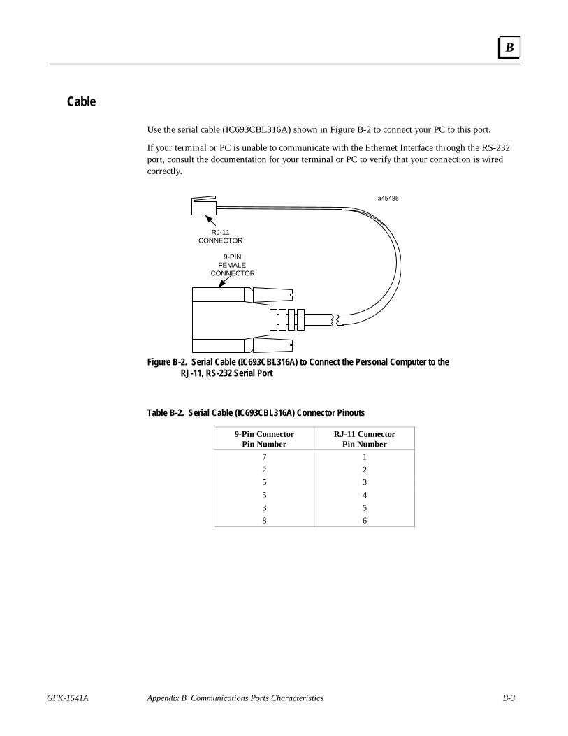
GFK-1541A Appendix B Communications Ports Characteristics B-3
B
Cable
Use the serial cable (IC693CBL316A) shown in Figure B-2 to connect your PC to this port.
If your terminal or PC is unable to communicate with the Ethernet Interface through the RS-232port, consult the documentation for your terminal or PC to verify that your connection is wiredcorrectly.
Figure B-2. Serial Cable (IC693CBL316A) to Connect the Personal Computer to theRJ-11, RS-232 Serial Port
Table B-2. Serial Cable (IC693CBL316A) Connector Pinouts
9-Pin ConnectorPin Number
RJ-11 ConnectorPin Number
7 1
2 2
5 3
5 4
3 5
8 6
a45485
RJ-11CONNECTOR
9-PINFEMALE
CONNECTOR

B-4 TCP/IP Ethernet Communications for the Series 90 PLC User's Manual – April 1999 GFK-1541A
B
RS-485, 15-Pin, D-Type Port
The 15-pin, D-type, RS-485 port is used by the Series 90-30 Ethernet Interface and the Series 90-70 Ethernet Interface (Type 2) only. It is used to connect to the PC Software Loader when thecommunications software in the Ethernet Interface needs to be updated. The Series 90-30CPU364 Embedded Ethernet Interface uses the RJ-11 port to connect to the Software Loader.
An RS-232 to RS-485 converter is required to interface to systems that provide RS-232 compatibleinterfaces.
Port Settings
The serial port of the terminal or PC that is connected to the Ethernet Interface must use the samecommunications parameters as the Ethernet Interface.
The default values for the Software Loader port are 19,200 bps, 8 bits, Odd parity, and 1 stop bit.If the Ethernet Interface is configured with default values for this port, or the Ethernet Interfacehas not been configured, use these default values. If the Ethernet Interface is configured withnon-default values for this port, use those values for the serial port settings of the terminal or PC.
Port Pinouts
Table B-3. Software Loader Port Pinout
Pin Number Signal Name Description1234
ShieldNo ConnectionNo ConnectionNo Connection
5678
+5V *RTS (A)Signal GroundCTS (B’)
+5V Power for RS-232/485 ConverterRequest To SendSignal Ground, 0VClear To Send
9101112
RT *RD (A’)RD (B’)SD (A)
Terminating Resistor for RD **Receive DataReceive DataSend Data
131415
SD (B)RTS (B)CTS (A’)
Send DataRequest To SendClear To Send
* Signals available at the Connector but are not included in the RS-485 specification.SD (Send Data) and RD (Receive Data) are the same as TXD and RXD (used in the Series Six PLC).(A) and (B) are the same as - and + . A and B denote outputs, and A’ and B’ denote inputs.
** Termination resistance for the Receive Data (RD) signal needs to be connected only on units at theend of multidrop lines. This termination is made by connecting a jumper between pins 9 and 10inside the 15-pin D-shell; the termination is provided in the adapters and cables specified inTable B-4.

GFK-1541A Appendix B Communications Ports Characteristics B-5
B
Part Numbers for GE Fanuc Cables and Converters
It is recommended that you use cables available from GE Fanuc Automation - NA to connect yourPC to this port. Refer to the table below for part numbers.
Table B-4. Cables for Connecting the 15-Pin, D-Type, RS-485 Port to the RS-232 Port on Your PC
Part Number Description
IC690ACC901 GE Fanuc/Horner Mini Converter with Cable (see the followingfigure.)
or
IC690ACC900 GE Fanuc Converter only (requires cable IC690CBL303 andeither IC690CBL702 or IC690CBL705 below)
IC690CBL303 15-pin RS-422 Serial Cable
IC690CBL702 9-pin RS-232 Serial Cable
IC690CBL705 25-pin RS-232 Serial Cable
Port Cable
The figure below illustrates cable assembly IC690ACC901. This cable assembly is needed toconnect the 9-pin or 25-pin serial port on a personal computer to the 15-pin, D-type, RS-485 porton the Ethernet Interface. Use the 9-pin to 25-pin adapter to connect to the 25-pin serial port onthe personal computer.
Figure B-3. Software Loader Cable Assembly (IC690ACC901)
a45484c
Part Number 9-PinFemale
Connector25-PinFemale
Connector9-PinMale
Connector
HE
693S
NP
232
SN
P T
O R
S23
2A
DA
PT
ER
HE
693XT
AD
P
TO THE 15-PIN, D-TYPE, RS-485 PORTON THE ETHERNET INTERFACE
TO THE 9-PIN SERIAL PORTON THE PERSONAL COMPUTER
Use the 9-pin to 25-pin adapter to connect tothe 25-pin serial port on the personal computer
NOTE:

B-6 TCP/IP Ethernet Communications for the Series 90 PLC User's Manual – April 1999 GFK-1541A
B
10BaseT Port
The Series 90-30 CPU364 Embedded Ethernet Interface and the Series 90-70 Ethernet Interface(Type 2) are equipped with a 10BaseT port for direct connection to a 10BaseT (twisted pair)network without an external transceiver. The 10BaseT port on the Ethernet Interface is connectedto an external 10BaseT hub or repeater by a twisted pair cable.
Your 10BaseT twisted pair cables must meet the applicable IEEE 802 standards.
This section provides the information you need to specify the 10BaseT twisted pair cables,including 10BaseT port pinouts and cable diagrams.
Port Pinouts
The 10BaseT port is located on the front of the Ethernet Interface. This port is an 8-pin RJ-45“modular phone jack” connector. It is used to connect the Ethernet Interface to a 10BaseT hub orrepeater. Connector pinouts are shown in Table B-5.
Table B-5. 10BaseT Port Pinouts
Pin Number Signal Description1 TD+ Transmit Data +
2 TD– Transmit Data –
3 RD+ Receive Data +
4 NC No connection
5 NC No connection
6 RD– Receive Data –
7 NC No connection
8 NC No connection
Note
Pinouts are provided for troubleshooting purposes only. 10BaseT cables arereadily available from commercial distributors. GE Fanuc recommendspurchasing rather than making 10BaseT cables.

GFK-1541A Appendix B Communications Ports Characteristics B-7
B
Network Connection
Connection of the Ethernet Interface to a 10BaseT network is shown below:
10BaseT
10BaseT
Twisted Pair
Cable
10BaseT Hub
a45628
To
Other Network
Devices
Ethernet Interface
Figure B-4. Connection to a 10BaseT Network

B-8 TCP/IP Ethernet Communications for the Series 90 PLC User's Manual – April 1999 GFK-1541A
B
10Base2 Port
The Series 90-70 Ethernet Interface (Type 2) is equipped with a 10Base2 port for directconnection to a 10Base2 (thin wire) network without an external transceiver. The 10Base2 porton the Ethernet Interface is directly connected to the 10Base2 network cables by a “T” or “F”connector.
Your 10Base2 network cables and connectors must meet the applicable IEEE 802 standards.
Information in this section includes 10Base2 port pinouts and cable diagrams.
Port Pinouts
The 10Base2 port is located on the front of the Series 90-70 Ethernet Interface. This port is afemale BNC coaxial connector. It is used to connect the Ethernet Interface directly to the 10Base2network cables. Connector pinouts are shown in Table B-6.
Table B-6. 10Base2 Port Pinouts
Pin Number Signal DescriptionS TD/RD Transmit and Receive Data
G GND Shield Ground
Note
Pinouts are provided for troubleshooting purposes only. 10Base2 cables arereadily available from commercial distributors. GE Fanuc recommendspurchasing rather than making 10Base2 cables.

GFK-1541A Appendix B Communications Ports Characteristics B-9
B
Network Connections
Connection of the Ethernet Interface to a 10Base2 network is shown below:
a45629
10Base2Cable
10Base2Cable
Terminator or to
Other NetworkDevices
ToOther Network
Devices
10Base2
Connector
Ethernet Interface
Figure B-5. Connection to a 10Base2 Network with “T” Connector
a45630
10Base2
Cable
Terminator or to
Other NetworkDevices
10Base2
Cable
ToOther Network
Devices
10Base2
Connector
Ethernet Interface
Figure B-6. Connection to a 10Base2 Network with “F” Connector

B-10 TCP/IP Ethernet Communications for the Series 90 PLC User's Manual – April 1999 GFK-1541A
B
AAUI Port
The Series 90-30 Ethernet Interface and the Series 90-30 CPU364 Embedded Ethernet Interfaceare equipped with an Apple Attachment Unit Interface (AAUI) port for connecting to the network.Compatible transceivers can be purchased that support 10Base5 and 10Base2 coaxial cables aswell as twisted pair and fiber optic cables. The AAUI standard makes your selection oftransceiver and trunk cable medium transparent to the Ethernet Interface.
Your network cables must meet the applicable IEEE 802.3 standards.
This section presents the information you need to specify the cables and related componentsrequired for Ethernet Communications, including AAUI port pinouts and cable diagrams.
Ethernet AAUI Port Pinouts
The AAUI port is a 14-pin D-type female connector. It is used to connect the Ethernet Interfaceto an external transceiver. Connector pinouts are shown in Table B-7.
Table B-7. Pinouts of the AAUI Port
Pin Number Signal Description1 FN Pwr +5V @ 1.9W2 DI-A Data In circuit A3 DI-B Data In circuit B4 Vc Voltage common5 CI-A Control In circuit A6 CI-B Control In circuit B7 +5V +5V from host8 +5V Secondary +5V from host9 DO-A Data Out circuit A10 DO-B Data Out circuit B11 Vc Secondary Voltage Common12 -nc- Reserved13 -nc- Reserved14 FN Pwr Secondary +5V
SHELL PG Protective Ground (Conductive shelland shield)
Note
Pinouts are provided for troubleshooting purposes only. Cables are readilyavailable from commercial distributors. GE Fanuc recommends purchasingrather than making transceiver cables.

GFK-1541A Appendix B Communications Ports Characteristics B-11
B
Transceiver Configurations
Depending on your particular application, any of several types of user-supplied transceivers maybe used. Typical configurations for 10Base2 (thin wire) and 10BaseT (twisted pair) are shown inthe following figures.
Note
Transceivers must be compatible with the IEEE 802.3 standard and must havethe SQE option Enabled.
Caution
PLC power must be OFF when connecting or disconnecting the transceiver.
a45488
Transceiver Cable toEthernet Interface
10 Base 2Cable
BNC "T"
BNCConnector
Terminator or to
other devices
Ethernet Interface
AAUI
Figure B-7. 10Base2 Transceiver Configuration using BNC “T” Connector (IC649AEA101)

B-12 TCP/IP Ethernet Communications for the Series 90 PLC User's Manual – April 1999 GFK-1541A
B
Transceiver Cable toEthernet Interface
a45490
10 Base TCable
RJ-45Connector
Ethernet Interface
AAUI
Figure B-8. 10BaseT Transceiver Configuration (IC649AEA102)

GFK-1541A Appendix B Communications Ports Characteristics B-13
B
AUI Port
The Series 90-70 Ethernet Interface (Type 2) is equipped with an AUI port for connecting to thenetwork. The IEEE 802.3 AUI (Attachment Unit Interface) is standard across a variety ofdifferent physical media. Compatible transceivers can be purchased that support 10Base5 and10Base2 coaxial cables as well as twisted pair and fiber optic cables. The standard AUI makesyour selection of transceiver and trunk cable medium transparent to the Ethernet Interface.
Your cables must meet the applicable IEEE 802.3 standards.
This section presents the information you need to specify the cables and related componentsrequired for Ethernet Communications, including Attachment Unit Interface (AUI) port pinoutsand AUI cable diagrams.
Port Pinouts
The AUI port is a 15-pin D-type female connector. It is used to connect the Ethernet Interface toan external transceiver. Connector pinouts are shown in Table B-8.
Table B-8. Pinouts of the AUI Port
Pin Number Signal Description1 GND Signal Ground2 CP+ Collision Presence +3 TX+ Transmit +4 GND Signal Ground5 RX+ Receive +6 GND Signal Ground7 NC Not Connected8 GND Signal Ground9 CP- Collision Presence -10 TX- Transmit -11 GND Signal Ground12 RX- Receive -13 +12 +12 Volts14 GND Signal Ground15 NC Not Connected
SHELL Chassis Ground
Note
Pinouts are provided for troubleshooting purposes only. Cables are readilyavailable from commercial distributors. GE Fanuc recommends purchasingrather than making transceiver cables.

B-14 TCP/IP Ethernet Communications for the Series 90 PLC User's Manual – April 1999 GFK-1541A
B
AUI (Transceiver Cable)The figure below shows a typical cable configuration to connect the AUI port of theEthernet Interface to an external transceiver.
a44668c
EthernetInterface
PIN
15- P inMale
Transceiver
P IN
15- P inMale
15- P inFemale
S H E L L
15- P inFemale
1
2
3
4
5
67
8
9
10
11
12
13
14
15
1
2
3
4
5
67
8
9
10
11
12
13
14
15
G N D
C P +
TX+
G N D
R X +
G N D
G N D
CP-
TX-
G N D
RX-
+12V
G N D
S H E L L
Figure B-9. Transceiver Cable Connection
NotePinouts are provided for troubleshooting purposes only. Cables are readilyavailable from commercial distributors. GE Fanuc recommends purchasingrather than making transceiver cables.
Transceiver DescriptionDepending on your particular application, any of several types of user-supplied transceivers maybe used. The two most commonly used in industrial environments are: 10Base5 and 10Base2. Atypical 10Base2 configuration is shown in the figure below.
Transceiver Cable toEthernet Interface
15-PinFemale
Connector
P W R
SQE
XMT
RCV
C P
a44666
15-PinMale
Connector
10Base2Coaxia l
Cable
B N CConnector
B N C"T"
SQEmust be
O N.
NOTE
Ethernet Interface
AUI
Terminator or to
other devices
Figure B-10. 10Base2 Transceiver Configuration
Note
Transceivers must be compatible with the IEEE 802.3 standard and must havethe SQE option Enabled.
Caution
PLC power must be OFF when connecting or disconnecting the transceiver.

GFK-1541A C-1
PC Software Loader
The GE Fanuc Series 90 Ethernet Interface has its operating firmware stored in FLASH memoryas opposed to EPROMS. You can perform a firmware upgrade for your Ethernet Interface whilethe PLC remains powered on and running. However, Ethernet communication through yourInterface will be interrupted until the upgrade has completed successfully.
A firmware upgrade for the Ethernet Interface is provided on a floppy diskette. A FirmwareUpdate Utility, provided on the floppy diskette in both a Windows-based and a DOS-basedversion, controls the download of new firmware from the floppy diskette to the FLASH memory.To perform the upgrade using a personal computer (PC) running Windows 95, Windows 98, orWindows NT 4.0, refer to the section “Updating Firmware Under Windows” below forinstructions to use the WinLoader program. To perform the upgrade using a PC running MS-DOS (Revision 3.3 or higher), Windows 3.11, or Windows NT 3.51, refer to the section“Updating Firmware Under DOS and Windows 3.xx” later in this appendix for instructions to usethe PC Software Loader program. The program that you run on the PC is referred to as the”Firmware Update Utility” in the instructions that follow.
Note
For the Series 90-70 Ethernet Interface (Type 2) only, it is not possible to perform afirmware load to this Ethernet Interface while it is operating with an IC697 PLC CPUrunning firmware Release 4.12 through 5.50. Do not attempt to do so - the operationwill fail. Move the Interface to a IC697 PLC CPU system running firmware Release6.00 or higher to perform the firmware load.
Updating Firmware Under Windows
You will need an IBM compatible PC running Windows 95, Windows 98, or Windows NT 4.0,equipped with a 3.5 inch high-density diskette drive, and an RS-232 serial port. The firmwareupdate process requires 500 KB of hard drive space. If you are using Windows 3.xx or WindowsNT 3.51, follow the instructions in the “Updating Firmware under DOS” section.
To install the new firmware, perform the following steps
1. Connect one of the serial ports on your PC to the Software Loader Port on your EthernetInterface.
n For the Series 90-30 Ethernet Interface and the Series 90-70 Ethernet Interface (Type 2),use cable assembly IC690ACC901.
CAppendix

C-2 TCP/IP Ethernet Communications for the Series 90 PLC User's Manual – April 1999 GFK-1541A
C
n For the Series 90-30 CPU364 Embedded Ethernet Interface, use serial cableIC693CBL316A.
Exit any application that is using this PC serial port (such as PLC programming software).Connect the proper serial cable to the Ethernet Interface and to the PC. See Appendix B,“Communications Ports Characteristics”, for more information.
2. Insert the update diskette into the diskette drive of your PC.
3. Invoke the WinLoader Utility by either double clicking its icon displayed by WindowsExplorer, or use the “Run…” selection of the Start menu and specify the location of theWinLoader Utility, e.g. “a:\winloader”.
4. The WinLoader Utility uses the COM1 port of your PC by default. If you connected yourcable to COM1, skip the rest of this step. If you connected your cable to a different com port,use WinLoader’s “COM Port” drop-down box to select the proper com port.
5. In most cases, you should not need to adjust the serial port settings that the WinLoader Utilityuses. No adjustment is necessary if your Ethernet Interface’s Software Loader portconfiguration is set for:
§ 19,200 baud§ ODD parity§ 8 data bits§ 0 modem turnaround time
If other settings are used, you must modify the serial port configuration used by the FirmwareUpdate Utility to use the same serial configuration as your Interface each time you run theFirmware Update Utility.
To do this, click the “Settings” button and select the matching serial port settings. Then click“OK” to activate the new settings.
6. To prepare the Ethernet Interface to receive a firmware load, follow the steps below:
With your Ethernet Interface installed in a PLC, powered on and functioning, press the restartbutton near the top of your Ethernet Interface and hold it down for five seconds. When thebutton is first pressed, all green LED indicators will go out. After five seconds, the bottomLED will go on, indicating that your Interface will enter the load state when the button isreleased. Release the button. All LEDs will flash briefly and then begin to blinksimultaneously. At this point, your Interface is ready to accept a firmware load. (Note: Ifyou hold the restart button down too long, the Ethernet Interface will enter maintenance moderather than firmware load mode. To return to operational mode, press and hold the restartbutton briefly (less than 5 seconds). Then re-execute the instructions in this step.)
If all LEDs are not blinking after this step, but your Interface seems to operate normally whenfirst powered on, there may be a hardware failure of the loader port. Use the PLCprogramming software to check the PLC fault table for a "Module hardware fault" messagefrom the rack and slot location of your Interface. You can also check the text displayed by theEthernet Interface's local station manager NODE command for a "Power up diagnosticsresult" message about the Software Loader port. See TCP/IP Ethernet Communications forthe Series 90 PLC Station Manager Manual, GFK-1186, for details. The Firmware UpdateUtility will not function if there is a hardware failure of the Ethernet Interface SoftwareLoader port. The Interface will be inoperative until it is power cycled. It should be replaced.

GFK-1541A Appendix C PC Software Loader C-3
C
7. Click the “Update” button to begin loading the new firmware. A progress bar is displayedacross the bottom of the window. The firmware load will take approximately 3-4 minutes tocomplete at 38,400 baud rate.
8. Upon completion of the update, a dialog box will appear indicating the completion status ofthe update. If the load completed successfully, the Firmware Update Utility asks you if youwant to update another Interface. Click “No” if this is the last update. If there are more, click“Yes”, move the serial cable to the next Interface, adjust the serial settings if necessary,prepare the Interface to receive a load, and click “Update” again.
9. If the firmware load fails, a window appears indicating the specific error condition thatoccurred. Take appropriate steps to correct the error and retry the update. Refer toRestarting An Interrupted Firmware Upgrade below.
10. When the firmware load has completed, the Ethernet Interface will automatically restartitself. Disconnect the serial cable.
Place the label accompanying the floppy diskette marked “UPDATED TO FIRMWAREVERSION x.xx” adjacent to existing product label.
Restarting an Interrupted Firmware Upgrade
1. Carefully check the cables, the RS-232/RS-485 converter (if used), and all connections. It isimportant to use the recommended cable assembly or equivalent. Use of non-standard cables(especially cables that are very long) can inhibit the Firmware Update Utility fromsuccessfully communicating with the Ethernet Interface.
2. Briefly press and release the Ethernet Interface Restart button. Depending on how far theprevious upgrade progressed before it failed, your Ethernet Interface may restart in eitheroperational mode or firmware load mode. If all LEDs are blinking simultaneously, skip tostep 3 now.
If your Interface is in operational mode, press and hold the Restart button for five secondsuntil the lower LED lights. Release the button and verify that all LEDs are blinkingsimultaneously. If all LEDs are off, replace your Interface. Otherwise proceed to step 3.(Note: If you hold the restart button down too long, the Ethernet Interface will entermaintenance mode. To return to operational mode, press and hold the restart button briefly(less than 5 seconds). Then re-execute the instructions in this step.)
3. You must exit the Firmware Update Utility (on the PC) and start it again, then repeat theupdate process.
If your previous attempt progressed beyond the FLASH memory erase step, began loadingdata blocks, and then displayed an error message or stalled, try a lower baud rate. If you wereusing an MS-DOS box under Microsoft Windows, exit from Windows and run the FirmwareUpdate Utility directly from MS-DOS.
Updating Firmware Under DOS and Windows 3.xx
You will need an IBM PC/AT compatible PC running MS-DOS (Revision 3.3 or later), Windows3.11, or Windows NT 3.51, equipped with at least 640K free RAM, a 3.5 inch high-densitydiskette drive, and an RS-232 serial port. The firmware update process is faster when 1 MB ofhard drive space is also available.
C-4 TCP/IP Ethernet Communications for the Series 90 PLC User's Manual – April 1999 GFK-1541A
C
You may be able to run the Firmware Update Utility in an MS-DOS box under MicrosoftWindows if your PC has all of the following:
• A 486 or higher microprocessor;• A high speed serial port (16550AF or equivalent UART); and• Microsoft Windows 3.11 (including Windows for Workgroups 3.11), Windows 95,
Windows 98, or Windows NT.
If you are not sure your PC has all of these, you will probably save time by exiting from Windowsand running the Firmware Update Utility directly from MS-DOS. The upgrade will be faster andmore reliable.
Under Windows, run the loader in full screen mode for best performance.
To install the new firmware, perform the following steps
1. Connect either the COM1 or COM2 port on your PC to the Software Loader Port on yourEthernet Interface.
n For the Series 90-30 Ethernet Interface and the Series 90-70 Ethernet Interface (Type 2),use cable assembly IC690ACC901.
n For the Series 90-30 CPU364 Embedded Ethernet Interface, use serial cableIC693CBL316A.
If you also use your PC to run Logicmaster 90 through COM1 or COM2, simply move thecable connector from the PLC CPU to your Interface. The Firmware Update Utility is unableto use COM3 or COM4.
2. Insert the update diskette into the A or B floppy diskette drive of your PC.
3. At the C:\> prompt, type a:install (or b:install if the diskette is in drive B)followed by the Enter key. The install program will copy several files to your hard drive andthen run the Firmware Update Utility program. These files will be removed upon completionof the update.
Install can also run from the floppy drive directly if there is no hard drive or not enough spaceon the hard drive. To run from the floppy, type install at the A:\> (or B:\>) promptfollowed by the Enter key.
4. The Firmware Update Utility uses the COM1 port of your PC by default. If you connectedyour cable to COM1, skip the rest of this step. If you connected your cable to COM2, pressthe F3 key from the Firmware Update Utility main menu. Then use Tab to select COM2, andEnter to accept the new setting.
5. Do not press any function keys in the Firmware Update Utility main menu until your EthernetInterface is ready to receive a firmware load. Follow these steps:
With your Ethernet Interface installed in a PLC, powered on and functioning, press the restartbutton near the top of your Interface and hold it down for five seconds. When the button isfirst pressed, all LED indicators will go out. After five seconds, the bottom LED will go on,indicating that your Interface will enter the load state when the button is released. Releasethe button. All LEDs will flash briefly and then begin to blink simultaneously. At this point,your Interface is ready to accept a firmware load. (Note: If you hold the restart button downtoo long, the Ethernet Interface will enter maintenance mode. To return to operational mode,

GFK-1541A Appendix C PC Software Loader C-5
C
press and hold the restart button briefly (less than 5 seconds). Then re-execute theinstructions in this step.)
If all LEDs are not blinking after this step, but your Interface seems to operate normally whenfirst powered on, there may be a hardware failure of the Software Loader port. Use the PLCprogramming software to check the PLC fault table for a "Module hardware fault" messagefrom the rack and slot location of your Interface. You can also check the text displayed by theEthernet Interface's local station manager NODE command for a "Power up diagnosticsresult" message about the Software Loader port. See TCP/IP Ethernet Communications forthe Series 90 PLC Station Manager Manual, GFK-1186, for details.
The Firmware Update Utility will not function if there is a hardware failure of EthernetInterface Software Loader port. The Interface will be inoperative until it is power cycled. Itshould be replaced.
6. If the configuration data stored in your PLC for the Software Loader port of your EthernetInterface is identical to the default values (19,200 baud, ODD parity, 8 data bits, 1 stop bit, 0modem turnaround time), skip the rest of this step.
The Firmware Update Utility will be unable to communicate with your Ethernet Interfaceunless both use the same serial port settings. If your Ethernet Interface’s Software Loaderport configuration is different from the defaults for Ethernet Interface modules, you must setthe Firmware Update Utility to use the same serial configuration as your Interface each timeyou run the Firmware Update Utility program. Press the F2 function key from the FirmwareUpdate Utility main menu to select the Loader Baud Rate menu. Use the Up/Down Cursorand Tab keys to select serial port settings that are identical to the Logicmaster configurationof your Interface. Then type Enter to accept the new settings.
WARNING: The Firmware Update Utility communicates using 8 data bits. This item is notconfigurable from the Loader Baud Rate menu. The Firmware Update Utility will always failunless the Ethernet Interface’s Software Loader port is configured for 8 data bits.
7. From the Firmware Update Utility main menu, press the F1 function key to attach to theEthernet Interface. The message
<< Sending ATTACH - try # 1 >>
will appear. If all is well, this message will blink off briefly and then reappear. If the attachfails, check the serial connection and the Ethernet Interface Software Loader portconfiguration, and then carefully repeat steps 1 through 7.
8. When the
>> BOOT MODE ACTIVE <<
message appears, you can press the F2 function key to change the baud rate on both ends ofthe connection. Press the Tab key once to change from 19,200 to 38,400 baud. Select a lowerbaud rate by holding the Shift key down while pressing Tab. Press the Enter key to accept thenew setting.
9. Another
>> BOOT MODE ACTIVE <<
message will appear. Press the F1 function key to update the firmware. This message willappear:

C-6 TCP/IP Ethernet Communications for the Series 90 PLC User's Manual – April 1999 GFK-1541A
C
THIS WILL ERASE ALL FIRMWARE!
ONCE STARTED YOU CANNOT ABORT
ARE YOU SURE ?!? (Y/N)
WARNING: Pressing the 'y' or 'Y' key at this point will commit you to completing thefirmware load. The Interface will not function again until the load completes successfully.
Press the 'y' key to proceed. The firmware load will take approximately 3-4 minutes at 38,400baud, 5-6 minutes at 19,200 baud, or 9-10 minutes at 9,600 baud. Upon successfulcompletion, the files that were added to your hard drive are removed.
If the firmware load fails, please refer to Restarting An Interrupted Firmware Upgrade inthe previous section.
10. When the firmware load has completed, the Ethernet Interface will automatically restartitself. Disconnect the serial cable.
The Firmware Update Utility will remind you to attach a product upgrade identification labelto your Interface. Place the label accompanying the floppy diskette marked “UPDATED TOFIRMWARE VERSION x.xx” adjacent to existing product label.

GFK-1541A D-1
Using the IC697CMM742 with PLC CPUs(Versions 4.12 - 5.50)
The IC697CMM742 Ethernet Interface (Type 2) is designed for high-performance operation andconvenient installation with IC697 PLC CPU versions 6.00 and later. These PLC CPUs recognizeand support the Ethernet Interface (Type 2), and provide the high throughput demanded by thisproduct. GE Fanuc recommends use of IC697 PLC CPUs with version 6.00 and later firmware toobtain the full capabilities of the Ethernet Interface (Type 2).
Versions 1.10 and later of the Ethernet Interface (Type 2) also provide restricted operation withIC697 PLC CPUs running firmware versions 4.12 through 5.50. These notes describe the necessaryEthernet Interface configuration and restricted operation with these PLC CPUs.
The Ethernet Interface (Type 2) cannot be used with PLC CPU firmware versions prior to 4.12.
Ethernet Interface Installation and Configuration
The Ethernet Interface (Type 2) is installed in the main PLC rack as described in Procedure 1 inChapter 2, “Installing the Ethernet Interface”.
IC697 PLC CPU firmware versions 4.12 though 5.50 do not accept PLC configuration data for theEthernet Interface (Type 2). Thus, this Ethernet Interface cannot be configured as described inProcedure 2 of Chapter 2. An alternate Procedure 2 is provided below; this procedure uses a user-supplied computer terminal or equivalent plus the Station Manager software within the EthernetInterface to enter the necessary configuration data. The Station Manager is completely described inGFK-1186, TCP/IP Ethernet Communications for the Series 90 PLC Station Manager Manual.Please refer to this manual for complete details on connecting a terminal to the Station Managerserial port of the Ethernet Interface, and on the various Station Manager commands used within thisalternate Procedure 2.
DAppendix

D-2 TCP/IP Ethernet Communications for the Series 90 PLC User's Manual – April 1999 GFK-1541A
D
Alternate Procedure 2: Configuring the Ethernet Interface (with PLC CPU versions 4.12through 5.50)
IC697 PLC CPU firmware versions prior to version 6.00 do not accept configuration data for theEthernet Interface (Type 2). Thus the Ethernet Interface (Type 2) cannot be configured by theIC641 PLC Configuration software. Instead, a dummy module must be configured in place of theEthernet Interface; the Station Manager software within the Ethernet Interface is then used to enterconfiguration data directly at the module.
First, create a dummy entry in the PLC Configuration for the rack and slot where the EthernetInterface is installed.
1. Connect a PC running the IC641 PLC Configuration software to the PLC via the built-in serialport on the PLC CPU module. Then access the I/O Configuration screen of the IC641 PLCConfiguration software.
2. Move the cursor to the rack and slot where the Ethernet Interface (Type 2) is installed. Thisslot must be configured as a “3rd Party VME module” as follows: From the I/O Configurationscreen, press the vme soft key (F7). From the next screen, press the vme soft key (F1),then move the cursor to the 3RD PARTY VME MODULE selection and press the Enterkey to select. Press the Escape key to return to the I/O Configuration screen. The slotcontaining the Ethernet Interface will be displayed as “3PY VME”.
If there is no vme soft key in the I/O Configuration screen, configure the rack and slot wherethe Ethernet Interface (Type 2) is installed as a “Blank jumper” as follows: Press the m70_iosoft key (F1). From the next screen, press the other soft key (F7), then move the cursorto the BLANK SLOT INTERRUPT JUMPER selection and press the Enter key to select.Press the Escape key to return to the I/O Configuration screen. The slot containing theEthernet Interface will be displayed as “JUMPER”.
3. Press the Escape key to save the PLC configuration to disk.
4. Use of the dummy module type above will always result in a Configuration Mismatch error ateach power up, configuration store, or Ethernet Interface restart. To prevent this error fromputting the PLC into STOP/FAULT state, change the severity of this error as follows:
From the main PLC Configurator screen, press the cpu soft key (F2) to display the CPUconfiguration, then press the fltcfg key (F5) to display the Fault Categories. Press thedown arrow key () repeatedly until Fault Type is “System Config Mismatch”,then press the Tab key to change the Fault Category from “F” (= Fatal) to “D” (=Diagnostic). Press the Escape key twice to store the fault categories to the PLC CPU andreturn to the main PLC Configurator screen
5. Store the PLC configuration to the PLC.
Now configure the Ethernet Interface (Type 2) locally using its onboard Station Manager.Refer to GFK-1186, TCP/IP Ethernet Communications for the Series 90 PLC Station ManagerManual, for complete information on Station Manager operation.

GFK-1541A Appendix D Using the IC697CMM742 with PLC CPUs (Versions 4.12 - 5.50) D-3
D
6. Connect a standard ASCII terminal or PC-based terminal emulator to the Station Manager(RS-232) serial port on the Ethernet Interface. Use the NODE Station Manager command toverify that the terminal or emulator is properly communicating with the Station Managersoftware in the Ethernet Interface. A typical NODE command is shown below:
> nodeIC697 PLC Factory LAN Ethernet Interface (Type 2)Copyright (c) 1996. All rights reserved.Version 1.10 (25A1) TCP/IPVersion 1.00 (12A1) Software LoaderIP Address = 0.0.0.0MAC Address = 080019010688*** PLC CPU version (5.00) supports restricted LAN Interfaceoperation:*** SRTP server only (client operation is not permitted)*** LAN Interface cannot be configured with PLC Configurator*** (Use CHSOSW Station Manager cmd to enter moduleconfiguration)*** PLC CPU version 6.00 or higher is required for fulloperation
If the Ethernet Interface has not been previously configured, the NODE output will alsoindicate that the Ethernet Interface is waiting for a valid IP address.
7. Use the LOGIN Station Manager command to “log in” in order to access the Modify-level commands needed later. The LOGIN command is shown below:
> login
After entering the LOGIN command, the Station Manager prompts for the Modify-levelpassword:
Password:
Enter your password (which is not echoed). The default password is: system (lower case).If the password matches the current Modify-level password, a confirmation message isdisplayed; the Station Manager prompt changes from “>” to “=”.
8. Use the Modify-level MAINT Station Manager command to restart the Ethernet Interface intothe Maintenance state. The MAINT command is shown below:
= maintRestarting module into Maintenance state
The Ethernet Interface is restarted into the Maintenance state. After approximately 20 seconds,another NODE output is automatically generated when the restart is complete. The display will

D-4 TCP/IP Ethernet Communications for the Series 90 PLC User's Manual – April 1999 GFK-1541A
D
also indicate that the Ethernet Interface is in the Maintenance state; the Station Managerprompt is “*”. Modify-level login is not required in the Maintenance state.
9. Use the CHSOSW Station Manager commands to enter the configuration data for this EthernetInterface. The IP addressing parameters ( ip_address, subnet_mask, gateway, andname_server) must be set to values supplied by the person in charge of your network ( thenetwork administrator). TCP/IP network administrators are familiar with these parameters. It isimportant that these parameters are correct, otherwise the Ethernet Interface may be unable tocommunicate on the network and/or network operation may be corrupted. It is especiallyimportant that each node on the network is assigned a unique IP address.
Enter the IP Address as follows:
* chsosw ip_address <a.b.c.d> where <a.b.c.d> is the unique dotted-decimal IP address for this node.
Enter the Subnet Mask as follows:
* chsosw subnet_mask <a.b.c.d> where <a.b.c.d> is the dotted-decimal subnet mask for this network segment.
Enter the Gateway IP Address as follows:
* chsosw gateway <a.b.c.d> where <a.b.c.d> is the unique dotted-decimal IP address of the gateway device.
Enter the Name Server IP Address as follows:
* chsosw name_server <a.b.c.d> where <a.b.c.d> is the unique dotted-decimal IP address of the name server device.
The CHSOSW command may also be used to change the parameters for either serial port onthe Ethernet Interface in cases where the default serial port configuration values are not used.Refer to GFK-1186, TCP/IP Ethernet Communications for the Series 90 PLC Station ManagerManual, for further information.
A typical CHSOSW command is shown below:
* chsosw ip_address 10.0.0.1
Once entered, the configuration parameters are retained in non-volatile flash memory for useeach time the Ethernet Interface is powered up or restarted. Configuration needs to be re-entered only when changing one or more configuration parameters.

GFK-1541A Appendix D Using the IC697CMM742 with PLC CPUs (Versions 4.12 - 5.50) D-5
D
10. Use the SOSW Station Manager command to verify that all configuration parameters havebeen set to the proper values. A typical SOSW command is shown below:
* sosw<<< Soft Switch Data >>>
IP Address = 10.0.0.1 (TCP/IP values from SoftSwitches)Subnet Mask = 0.0.0.0Gateway = 0.0.0.0Name Server = 0.0.0.0
Port 1 (Station Manager): Port 2 (S/W Loader):Data Rate = 9600 Data Rate = 19200Parity = NONE Parity = ODDStop Bits = 1 Stop Bits = 1Flow Control = NONE Flow Control = NONETurnA Delay = NONE TurnA Delay = NONETimeout = LONG Timeout = LONG
Source of Soft Switches: Internal Backup
11. When all configuration parameters have been correctly entered, use the RESTART StationManager command to restart the Ethernet Interface into normal operation.The RESTART command is shown below:
= restartRestarting module
The Ethernet Interface is restarted into the Operational state. After approximately 20 seconds,another NODE output is automatically generated when the restart is complete. The NODEoutput should indicate the IP Address configured in Step 9, above. (The Subnet Mask,Gateway IP Address and Name Server IP Address can be displayed by the SOSW command,as described in Step 10, above.) The Ethernet Interface is now properly configured and readyfor use.
Please proceed to Procedure 3 in Chapter 2, “Installing the Ethernet Interface”, to verify properoperation of the Ethernet Interface with the new configuration data.

D-6 TCP/IP Ethernet Communications for the Series 90 PLC User's Manual – April 1999 GFK-1541A
D
Ethernet Interface Operational Restrictions
The Ethernet Interface (Type 2) operates with some restrictions when used with IC697 PLC CPUversions 4.12 through 5.50. These Operational Restrictions, together with differences in Startup,Station Manager and Software Loader operation, are described below.
1. COMMREQ operation is not supported. Any COMMREQ issued to the Ethernet Interface isignored; a COMMREQ Status (CRS) word is not returned to the PLC. Instead, the EthernetInterface generates an event in its internal exception log (Event = 1c; Entry 2 = 11H)indicating that the Channel API task is not active. The Ethernet Interface also generates anentry in the PLC Fault Table: (“LAN system-software fault; resuming”)
2. The Ethernet Interface returns neither LAN Interface Status (LIS) nor Channel Status data tothe PLC.
3. PLC CPU models IC697CPU73x and IC697CPU77x may limit the overall performance of aPLC used as a server device. Under heavy load from other clients and hosts on the network,the server PLC may generate errors with major error code 07, indicating that the volume ofrequests from the network have momentarily exceeded the processing capacity of the PLCCPU. The request will need to be retried. If possible, try to reduce the volume of requests tothe server PLC when this condition occurs. If the system design requires data rates beyond thecapacity of the server PLC CPU, please consider upgrading to a more powerful CPU model.
Startup
1. Upon each powerup or restart of the Ethernet Interface, or configuration store to the PLC, thefollowing entry will be generated in the PLC Fault Table for the slot containing the EthernetInterface: (“Reset of, addition of, or extra option module”).
2. When operating with PLC CPU versions prior to 6.00, the Ethernet Interface does not generatethe exceptions or PLC Faults that normally occur when Ethernet Interface does not receivemodule configuration from the PLC CPU.
3. Each powerup and restart of the Ethernet Interface takes approximately 20 seconds. This isroughly 10 seconds longer than required when the Ethernet Interface is used with PLC CPUversions 6.00 and later.
Station Manager
1. The STAT C command (PLC Driver status) does not display the current PLC CPU state(RUN/STOP and I/O ENABLED/ I/O DISABLED).
2. In the TALLY C command output (PLC Driver tallies), the “PlcSweep” tally does not countthe number of PLC sweeps. This tally should be ignored.
3. The STAT H command (Channel API status) always indicates “Channel API task notinitialized”

GFK-1541A Appendix D Using the IC697CMM742 with PLC CPUs (Versions 4.12 - 5.50) D-7
D
4. As detailed in the previous topic, “Ethernet Interface Installation and Configuration”, specialrestricted operation notification is displayed with the startup message and by the NODEcommand.
Software Loader
IC697 PLC CPU versions 6.00 and later gracefully allow option modules like the EthernetInterface to suspend communication with the PLC CPU while loading new firmware. Since thiscapability is not present in PLC CPU versions 4.12 - 5.50, special operations are required whenloading new firmware into the Ethernet Interface. Follow the steps in Appendix C, “PC SoftwareLoader”, to load new firmware into the Ethernet Interface; step 2 of the firmware installationprocess must be expanded, as described below:
(from Step 2)Hold the Reset pushbutton on the Ethernet Interface until the bottom LED (STATUS) turnsON. Upon releasing the pushbutton, all 4 LEDs will blink in unison. This signifies that theInterface is in the Software Loader state.
a. (new)After 18-20 seconds, the PLC CPU will indicate that communication with the EthernetInterface has been lost. A PLC Fault Table entry will be generated “Loss of option module”;all LEDs on the Ethernet Interface will turn OFF and remain so indefinitely.
2b. (new)Press the Restart pushbutton again. The Ethernet Interface will restart immediately without anycommunication to the PLC CPU. The OK LED will blink, turn OFF, and blink again. Afterapproximately two minutes, the Ethernet Interface will enter the Operational state. (Theabsence of PLC CPU communication is of no concern at this time.)
c. (new)Hold the Reset pushbutton on the Ethernet Interface until the bottom LED (STATUS) turnsON. This time, upon releasing the pushbutton, the OK LED will blink for approximately 30seconds, then all 4 LEDs will blink in unison to signify the Ethernet Interface is in theSoftware Loader state.
The Ethernet Interface can now safely accept the firmware update. Proceed with Steps 3 through 9in Appendix C. When the loading process is complete, the Ethernet Interface will automaticallyrestart. Proceed to new Step 10 to restore communication between the PLC CPU and the EthernetInterface.
10. (new)Once the Ethernet Interface begins to restart upon load completion (OK LED is blinking; otherLEDs are OFF), turn the PLC power supply OFF and then ON; this is necessary to establishcommunication between the PLC CPU and the Ethernet Interface.

Index
GFK-1541A Index-1
110Base2, 1-410Base2 Port, B-810Base2, BNC Port, Series 90-70 Ethernet
Interface (Type 2), 2-3210Base5, 1-410BaseF, 1-410BaseT, 1-310BaseT Port, B-610BaseT, RJ-45 Port, Series 90-30 CPU364
with Embedded Ethernet Interface, 2-1810BaseT, RJ-45 Port, Series 90-70 Ethernet
Interface (Type 2), 2-3210Broad36, 1-4
AAAUI port, B-10AAUI Port, 1-4AAUI Port, Series 90-30 CPU364 with
Embedded Ethernet Interface, 2-18AAUI Port, Series 90-30 Ethernet Interface,
2-5Abbreviations and Acronyms, A-1Abort Channel command (2001), 3-28Aborting a channel, 3-9Adapter (RS-232 to RS-485 converter), B-5Adapter Names, 4-21Aliases, 4-21Attachment of the Ethernet Interface to the
LAN, 1-3AUI port, 1-4AUI Port, 1-4, B-13AUI Port, Series 90-70 Ethernet Interface
(Type 2), 2-32
BBattery, 2-31Board Indicators, Series 90-30 CPU364 with
Embedded Ethernet Interface, 2-16Board Indicators, Series 90-30 Ethernet
Interface, 2-3Board Indicators, Series 90-70 Ethernet
Interface (Type 2), 2-30BOOTP, 2-42
CCables
Ethernet, 1-4Capabilities of the Ethernet Interface, 1-2
Channel Command, 3-2, 3-3Channel Commands, 3-9
Abort Channel (2001), 3-28Channel number, 3-12, 3-18, 3-24, 3-28, 3-29Command period, 3-12, 3-18, 3-24Establish Read Channel (2003), 3-11Establish Write Channel (2004), 3-17Local, 3-28, 3-30Number of repetitions, 3-12, 3-18, 3-24Retrieve Detailed Channel Status (2002), 3-29Send Information Report (2010), 3-23Timeout, 3-12, 3-18, 3-24
Channel Error bit, 3-34, 3-44Channel Status bits, 3-2, 3-4Channel Status words, 3-29Channels
Aborting, 3-9Establishing, 3-9Maximum that can be established, 3-3Monitoring, 3-44Numbers assigned, 3-12, 3-18, 3-24, 3-28, 3-29Re-tasking, 3-9Retrieving Detailed Status on, 3-10
Client PLC, 3-11, 3-15, 3-17Client/Server Capability, 1-1Command Block, 3-2, 3-3, 3-7COMMREQ Function Block, 3-2, 3-3, 3-6COMMREQ functions, maximum pending,
3-45COMMREQ Status word, 3-2, 3-4, 3-44
Minor Error Codes, 3-37Pointer, 3-8
COMMREQs, 3-1Communications Ports Characteristics, B-1Communications Request, 3-2Communications Requests, programming, 3-1Communications Status words, 3-31, 3-35Configuration Parameters for the Series 90-30
CPU364 with Embedded EthernetInterface, 2-22
Configuration Parameters for the Series 90-30Ethernet Interface, 2-9
Configuration Parameters for the Series 90-70Ethernet Interface (Type 2), 2-37
Configuration Planning, 4-7Configuring Ethernet Global Data, 4-16Configuring Multiple Gateways, 5-6Configuring the Series 90-30 CPU364 with
Embedded Ethernet Interface, 2-21Configuring the Series 90-30 Ethernet
Interface, 2-8Configuring the Series 90-70 Ethernet Interface
(Type 2), 2-36Consumed Data Exchange Definition, 4-14Consumer, 4-3Converter (RS-232 to RS-485 adapter), B-5CRS word, 3-4, 3-44

Index
Index-2 TCP/IP Ethernet Communications for the Series 90 PLC User's Manual–April 1999 GFK-1541A
DData Block, 3-3, 3-8
Length, 3-7Data Transfer bit, 3-34, 3-45Data Transfers with One Repetition, 3-45DCS words, 3-4, 3-35DDP Name Resolution, 5-10Default Station Address Label, Series 90-30
CPU364 with Embedded EthernetInterface, 2-18
Default Station Address Label, Series 90-30Ethernet Interface, 2-5
Default Station Address Label, Series 90-70Ethernet Interface (Type 2), 2-33
Detailed Channel Status words, 3-4, 3-29, 3-35Determining if an IP address has been used,
2-14, 2-28, 2-43DNS Name Resolution, 5-10
EError Codes, COMMREQ
Minor Error Codes, 3-37Establish Read Channel command (2003), 3-11Establish Write Channel command (2004),
3-17Establishing a channel, 3-9Ethernet Communications System, 1-2Ethernet Controller Board Installation, 2-35Ethernet Global Data
Configuration Planning, 4-7Configuration-Based, 4-13Configuring, 4-16Consumed Data Exchange Definition, 4-14Consumer, 4-3Effect of PLC modes and actions on, 4-6Examples, 4-17Exchange, 4-4Exchange Status Word, 4-23Group Usage, 4-22Maximum data size, 4-7Maximum Number of Exchanges, 4-7Number of Variables, 4-7Operation, 4-5PLC Timing Considerations, 4-9Produced Data Exchange Definition, 4-13Producer, 4-2Timestamping, 4-25
Ethernet Global Data (EGD), 4-1Ethernet Interface, 1-1
Attachment to the LAN, 1-3Capabilities, 1-2
Ethernet Ports, Series 90-30 CPU364 withEmbedded Ethernet Interface, 2-17
Ethernet Ports, Series 90-70 Ethernet Interface(Type 2), 2-32
Ethernet Software, 1-5Exchange, 4-4Exchange ID, 4-4Exchange Status Word
Ethernet Global Data, 4-23
FFault table, 6-2Fiber-optic cable, 1-4Flash memory, 1-5FT Output of the COMMREQ Function Block,
3-4, 3-31, 3-32Fuse, 2-33Fuse, Series 90-30 CPU364 with Embedded
Ethernet Interface, 2-18
GGateway address, 2-10, 2-23, 2-37Gateways, 5-3Glossary of Terms, A-1, A-2Group Usage, 4-22
HHardware failure, 2-13, 2-27, 2-42Hardware Overview, Series 90-30 CPU364
With Embedded Ethernet Interface, 2-15Hardware Overview, Series 90-30 Ethernet
Interface, 2-2Hardware Overview, Series 90-70 Ethernet
Interface (Type 2), 2-29Host Communications Toolkit, 1-1, 1-2How to Make it Work, 1-5
IIC693CMM321, 1-1IC693CPU364, 1-1IC697CMM742, 1-1Installing the Series 90-30 CPU364 with
Embedded Ethernet Interface, 2-19Installing the Series 90-30 Ethernet Interface,
2-6Installing the Series 90-70 Ethernet Interface
(Type 2), 2-34IP address, 2-10, 2-23, 2-37
Configuration, 2-23, 2-37Determining if it has been used, 2-14, 2-28, 2-43Isolated network, 2-23, 2-38

Index
GFK-1541A Index Index-3
IP Addresses Reserved for Private Networks,5-2
IP Addresses, Multicast, 5-2IP addressing, 5-1
JJumper, 10Base2 Port, Series 90-70 Ethernet
Interface (Type 2), 2-33
LLadder programming, 3-40LAN Interface OK bit, 3-34LAN Interface Status bits, 3-2LAN OK bit, 3-34LED test, 2-16, 2-30LED Test, 2-3LEDs, 2-3, 2-11, 2-12, 2-13, 2-16, 2-25, 2-26,
2-27, 2-30, 2-40, 2-41, 2-42LIS bits, 3-4Loading Ethernet Interface software, 2-3Loading Ethernet Interface software, 2-16,
2-30Local Channel commands, 3-28, 3-30Local PLC, 3-11, 3-15, 3-17Local Table Name Resolution, 5-10Logic program controlling execution of the
COMMREQ, 3-4
MMAC Addresses, 5-11Maintenance state, 2-13, 2-17, 2-27, 2-31, 2-42Maintenance State, 2-4Media, 1-4Memory types, PLC, 3-13Monitoring the communications channel, 3-44Multicast IP Addresses, 5-2Multiple Gateways and Subnets, 5-4Multiple Gateways, Configuring, 5-6
NName Assignment, 5-8Name Resolution, 5-9Name Server IP address, 2-10, 2-23, 2-37Name Usage, 5-10Naming Conventions, 4-10Network Address, 3-10, 3-14, 3-16, 3-22, 3-25,
3-27Network Address Naming Architecture, 5-8Network Administration Support, 5-1
Number of repetitions for a ChannelCommand, 3-12, 3-18, 3-24
OOK Output of the COMMREQ Function
Block, 3-32Older Series 90-70 PLC CPUs, Using
IC697CMM742 with, D-1Operational state, 2-13, 2-27, 2-42
PPart numbers for the Ethernet Interfaces, 1-1PC Software Loader, 1-5Period for Channel Commands, 3-12, 3-18,
3-24PING Station Manager command, 2-14, 2-28,
2-43Pinging the TCP/IP Ethernet Interfaces on the
Network, 2-14Pinging the TCP/IP Interfaces on the Network,
2-28, 2-43PLC Fault Table, 6-2PLC memory types, 3-13Ports
10Base2, B-810BaseT, B-6AAUI, B-10AUI, B-13RS-232, B-2RS-485, B-4
Ports Characteristics, B-1Ports, Ethernet, Series 90-30 CPU364 with
Embedded Ethernet Interface, 2-17Ports, Ethernet, Series 90-70 Ethernet Interface
(Type 2), 2-32Ports, Serial, Series 90-30 CPU364 with
Embedded Ethernet Interface, 2-17Ports, Serial, Series 90-30 Ethernet Interface,
2-4Ports, Serial, Series 90-70 Ethernet Interface
(Type 2), 2-32Powering-up the Ethernet Interface for the
Series 90-30 CPU364 with EmbeddedEthernet Interface, 2-25
Powering-up the Ethernet Interface for theSeries 90-30 Ethernet Interface, 2-11
Powering-up the Ethernet Interface for theSeries 90-70 Ethernet Interface (Type 2),2-40
Power–up problems, 2-11, 2-25, 2-40Private Networks, IP addresses, 5-2Problems During Power up, 2-11, 2-25, 2-40

Index
Index-4 TCP/IP Ethernet Communications for the Series 90 PLC User's Manual–April 1999 GFK-1541A
Produced Data Exchange Definition, 4-13Producer, 4-2Producer ID, 4-2Programming Communications Requests, 3-1
QQuick Guide to the Manual, 1-6
RReloading Ethernet Interface software, 2-3Reloading Ethernet Interface software, 2-16,
2-30Remote PLC, 3-11, 3-15, 3-17Repetitions, number of for Channel
Commands, 3-12, 3-18, 3-24Requirements to Install the Series 90-30
CPU364 with Embedded EthernetInterface, 2-19
Requirements to Install the Series 90-30Ethernet Interface, 2-6
Requirements to Install the Series 90-70Ethernet Interface (Type 2), 2-34
Resource problem bit, 3-34Restart, 2-3Restart, 2-16, 2-30Restart Pushbutton, Series 90-30 CPU364 with
Embedded Ethernet Interface, 2-16Restart Pushbutton, Series 90-30 Ethernet
Interface, 2-3Restart Pushbutton, Series 90-70 Ethernet
Interface (Type 2), 2-30Re-tasking a channel, 3-9Retrieve Detailed Channel Status command
(2002), 3-29RJ11 Serial Port, B-2RS-232, RJ-11 Port, Series 90-30 CPU364
with Embedded Ethernet Interface, 2-17RS-232, RJ-11 Port, Series 90-30 Ethernet
Interface, 2-4RS-232, RJ-11 Port, Series 90-70 Ethernet
Interface (Type 2), 2-32RS-232, RJ11 Serial Port, B-2RS-485, 15-Pin, D-Type Port, B-4RS-485, 15-Pin, D-Type Port, Cables and
Converters, B-5RS-485, D-type Port, Series 90-30 Ethernet
Interface, 2-5RS-485, D-Type Port, Series 90-70 Ethernet
Interface (Type 2), 2-32
SSample ladder program, 3-40Send Information Report command (2010),
3-23Sequencing communications requests, 3-45Serial Number Label, Series 90-30 CPU364
with Embedded Ethernet Interface, 2-18Serial Number Label, Series 90-30 Ethernet
Interface, 2-5Serial port configuration
Data rate, 2-10, 2-24, 2-39Flow control, 2-10, 2-24, 2-39Parity, 2-10, 2-24, 2-39Stop bits, 2-10, 2-24, 2-39Timeout, 2-10, 2-24, 2-39Turnaround delay, 2-10, 2-24, 2-39
Serial Ports, Series 90-30 CPU364 withEmbedded Ethernet Interface, 2-17
Serial Ports, Series 90-30 Ethernet Interface,2-4
Serial Ports, Series 90-70 Ethernet Interface(Type 2), 2-32
Series 90 PLC memory types, 3-13Series 90-30 CPU364 with Embedded Ethernet
Interface10BaseT, RJ-45 Port, 2-18AAUI (Transceiver) Port, 2-18Configuration Parameters, 2-22Configuring, 2-21Hardware Overview, 2-15Installing, 2-19Powering-up the Ethernet Interface, 2-25Replaceable Fuse, 2-18Requirements to Install, 2-19Restart Pushbutton, 2-16RS-232, RJ-11 Port, Station Manager andSoftware Loader, 2-17Serial Number Label, 2-18States, 2-26Station Address Label, 2-18
Series 90-30 CPU364 WITH EmbeddedEthernet Interface
Board Indicators, 2-16Series 90-30 CPU364 with Embedded TCP/IP
Ethernet Interface, 2-15Series 90-30 CPU364 with Ethernet Interface
Ethernet Ports, 2-17Serial Ports, 2-17
Series 90-30 Ethernet InterfaceAAUI (Transceiver) Port, 2-5Board Indicators, 2-3Configuration Parameters, 2-9Configuring, 2-8Hardware Overview, 2-2Installing, 2-6

Index
GFK-1541A Index Index-5
Powering-up the Ethernet Interface, 2-11Requirements to Install, 2-6Restart Pushbutton, 2-3RS-232, RJ-11 Port, 2-4RS-232, RJ-11 Port (Software Loader Port), 2-5Serial Number Label, 2-5Serial Ports, 2-4States, 2-12Station Address Label, 2-5
Series 90-30 TCP/IP Ethernet Interface, 2-2Series 90-70 Ethernet Interface
AUI (Transceiver) Port, 2-32States, 2-41Using with PLC CPUs (Versions 4.12 - 5.50),D-1
Series 90-70 Ethernet Interface (Type 2)10Base2, BNC Port, 2-3210BaseT, RJ-45 Port, 2-32Board Indicators, 2-30Configuration Parameters, 2-37Configuring, 2-36Ethernet Ports, 2-32Hardware Overview, 2-29Installing, 2-34Jumper, 10Base2 Port, 2-33Powering-up the Ethernet Interface, 2-40Requirements to Install, 2-34Restart Pushbutton, 2-30RS-232, RJ-11 Port, 2-32RS-485, D-Type Port, 2-32Serial Ports, 2-32Service Option Connetor, 2-31Station Address Label, 2-33
Series 90-70 TCP/IP Ethernet Interface(Type 2), 2-29
Server Capability, 1-1Server PLC, 3-11, 3-15, 3-17Service Option Connector, 2-31Service Option Connector, Series 90-70
Ethernet Interface (Type 2), 2-31Simple isolated network configuration, 2-23,
2-38Simple Network Time Protocol, 4-25SNTP, 4-25Software Loader, 2-13, 2-27, 2-42Software Loader Port, Seies 90-30 CPU364
Ethernet Interface, B-2Software Loader Port, Series 90-30 CPU364
with Embedded Ethernet Interface, 2-17Software Loader Port, Series 90-30 Ethernet
Interface, 2-5Software Loader Port, Series 90-70 Ethernet
Interface (Type 2), 2-32Software Loader Port, Series 90-70 Ethernet
Interface (Type 2) and Series 90-30Ethernet Interface, B-4
SQE, 2-35
States of the Series 90-30 CPU364 withEmbedded TCP/IP Ethernet Interface,2-26
States of the Series 90-30 TCP/IP EthernetInterface, 2-12
States of the Series 90-70 TCP/IP EthernetInterface (Type 2), 2-41
Station Address Label, Series 90-30 CPU364with Embedded Ethernet Interface, 2-18
Station Address Label, Series 90-30 EthernetInterface, 2-5
Station Address Label, Series 90-70 EthernetInterface (Type 2), 2-33
Station Manager Port, B-2Station Manager Port, Series 90-30 CPU364
with Embedded Ethernet Interface, 2-17Station Manager Port, Series 90-30 Ethernet
Interface, 2-4Station Manager Port, Series 90-70 Ethernet
Interface (Type 2), 2-32Station Manager software, 1-5Status address location, 2-22Status bits, 3-2, 3-4, 3-31, 3-32Status data, Channel Commands, 3-4Status on a channel, 3-10Subnet Addressing and Subnet Masks, 5-4Subnet mask, 2-10, 2-23, 2-37, 5-4Subnets and Multiple Gateways, 5-4
TTerms, Glossary, A-2Thick wire, 1-4Thin wire, 1-4Time units for command period, 3-12, 3-18,
3-24Timeout for Channel Commands, 3-12, 3-18,
3-24Timestamping EGD Exchanges, 4-25Timestamping, Ethernet Global Data, 4-25Transceiver Port, Series 90-30 CPU364 with
Embedded Ethernet Interface, 2-18Transceiver Port, Series 90-30 Ethernet
Interface, 2-5Transceiver Port, Series 90-70 Ethernet
Interface (Type 2), 2-32Troubleshooting
Ladder programs, 3-43Using LEDs, 2-12, 2-26, 2-41Using PLC Fault Table, 6-2Using the Status bits and CommunicationsStatus words, 3-32
Troubleshooting the Ethernet Interface, 6-1

Index
Index-6 TCP/IP Ethernet Communications for the Series 90 PLC User's Manual–April 1999 GFK-1541A
UUpdating Ethernet Interface software, 2-3Updating Ethernet Interface software, 2-16,
2-30Using the IC697CMM742 with PLC CPUs
(Versions 4.12 - 5.50), D-1
WWaiting for configuration from PLC, 2-13,
2-27, 2-42Waiting for IP address, 2-13, 2-27, 2-42