the certified nonroad compression … certified nonroad compression-ignition engines the ter...
TRANSCRIPT

43391601-USA-EPA IV-CARB12.07-0.03
Printed in Germany
INSTRUCTION BOOK
33
INCLUDES SUPPLEMENTAL INFORMATION TO THE
OWNER’S MANUAL FOR 2008 AND LATER EPA CERTIFIED
NONROAD COMPRESSION-IGNITION ENGINES
INCLUDES SUPPLEMENTAL INFORMATION TO THE
OWNER’S MANUAL FOR 2008 AND LATER CALIFORNIA
REGULATIONS FOR HEAVY-DUTY OFF-ROAD ENGINES
2W353W354W354W35T

A new HATZ Diesel engine - working for you
This engine is intended only for the purpose determined and has been tested by the manufacturer ofthe equipment in which it is installed. Using it in any other manner contravenes the intended purpose.For danger and damage due to this, Motorenfabrik HATZ assumes no liability. The risk is with the user only.Use of this engine in the intended manner presupposes compliance with the maintenance and repairinstructions laid down for it. Noncompliance leads to engine breakdown.
Please do not fail to read this operating manual before starting the engine for the first time.This will help you to avoid accidents, ensure that you operate the engine correctly and assist you in complying with the maintenance intervals in order to ensure long-lasting, reliable performance.
Please follow all maintenance references carefully including the schedule for 2008 and later EPA certified nonroad compression-ignition engines and for 2008 and later CARB certified off-road engines to prevent our environment.
Please pass this Instruction Manual on to the next user or to the following engine owner.
The worldwide HATZ Service Network is at your disposal to advise you, supply with spare parts andundertake servicing work.You will find the address of your nearest HATZ service station in the enclosed list.
Use only original spare parts from HATZ. Only these parts guarantee a perfect dimensional stabilityand quality. The order numbers can be found in the enclosed spare parts list. Please note the spareparts kits shown in Table M00.
We reserve the right to make modifications in the course of technical progress.
MOTORENFABRIK HATZ GMBH & CO KG
1

Page
1. Important safety notes when operating the engine 4
2. Description of the engine 6
3. General notes 103.1. Technical data 103.2. Transport 113.3. Instructions for installation 113.4. Load on engine 113.5. EPA /CARB- type plates 123.6. Emission-related installation
instructions 13
4. Operation 134.1. Before initial start-up 134.1.1. Engine oil 134.1.2. Coolant 144.1.3. Fuel 164.2. Starting the engine 184.2.1. Preparations for starting 184.2.2. Electric starter 194.3. Stopping the engine 20
5. Maintenance 225.1. Maintenance chart 22
5.2. Maintenance every 8 - 15operating hours 24
5.2.1. Check engine oil level 245.2.2. Check combustion air intake area 245.2.3. Check air cleaner maintenance
indicator 255.2.4. Check radiator fins for contamination 255.2.5. Check coolant level 25
Page
5.3. Maintenance every 250operating hours 26
5.3.1. Change engine oil 265.3.2. Check water trap 265.3.3. Clean the radiator fins 275.3.4. Check screw connections 285.3.5. Check the Vee belt 28
5.4. Maintenance every 500operating hours 29
5.4.1. Replace primary fuel filter 295.4.2. Replace the engine oil filter 305.4.3. Air cleaner maintenance 315.5. Maintenance every 1000
operating hours 345.5.1. Renew the fuel filter 34
5.6. Maintenance: every 4 years 355.6.1. Replacement of coolant 35
6. Malfunctions – causes – remedies 37
7. Work on the electrical system 41
8. Storage out of use 41
SUPPLEMENTAL INFORMATION TO THE OWNER’S MANUAL FOR 2008 AND LATER EPA CERTIFIED NONROAD COMPRESSION IGNITION ENGINES 43
SUPPLEMENTAL INFORMATION TO THE OWNER’S MANUAL FOR 2008 AND LATER CALIFORNIA REGULATIONS FOR HEAVY-DUTYOFF-ROAD ENGINES 57
3
Contents
This symbol identifies important safety precautions.Please comply with these most carefully in order to avoid any risk of injury to persons ordamage to materials.General legal requirements and safety regulations issued by the competent authorities orindustrial accident insurers must also be complied with.

1. Important safety notes when operating the engine
HATZ diesel engines are efficient, strong and durable. For this reason they are mostly installed onequipment used for commercial purposes.The manufacturers of such equipment must observe any relevant equipment safety regulations whenthe engine forms part of an overall system.A few general points concerning operating safety should nonetheless be noted.Depending on the engine's operating and installation conditions, equipment manufacturers and theirusers may have to fit safety or protective devices in order to prevent improper use. Examples:
– Exhaust system components as well as the surface of the engine will naturally be hot and must notbe touched while the engine is running or until it has cooled down after being stopped.
– Incorrect wiring or improper operation of the electrical system may cause sparking and must there-fore be avoided.
– Provide protection against contact with rotating parts once the engine is connected to the drivenequipment or machine.HATZ protective guards are available for the belt drive of the cooling fan and alternator drive systems.
– Always observe the start-up information in the operating instructions before starting the engine.
– Mechanical starting devices should not be operated by children or persons deficient in physicalstrength.
– Check that all safety devices are in place before starting the engine.
– Ensure that operation, maintenance and repair of the engine are undertaken by suitably trained personnel only.
– Protect the starter key against unauthorised use.
– Do not run the engine in closed or insufficiently ventilated rooms.Do not breathe in emissions – danger of poisoning!
– Also fuel and lubricants could contain poisonous components. Please follow the appropriate instructions of the mineral oil producer.
– Radiator protection fluids are detrimental to health. Thus, they may only be stored in closed originalcontainers and in a place inaccessible to non-authorized persons. Eye and skin contact must beavoided. Comply with the manufacturer’s instructions
4

Important safety notes when operating the engine
– The engine must be stopped before performing any maintenance, cleaning or repair work.
– It is essential to stop the engine before refilling the fuel tank.Never refuel near a naked flame or sparks which could start a fire. Don’t smoke. Don’t spill fuel.
– Keep explosive materials as well as flammable materials away from the engine because the exhaustgets very hot during operation.
– Never spill consumables, such as fuel, oil or radiator protection fluid over hot engine components.The fluid might catch fire.
– Work on the cooling system must not be performed while the engine is warm - risk of scalding !The cooling system is pressurized.
– Wear close-fitting clothing only when working on the engine while it is running.Please don’t wear necklaces, bracelets or any other objects which you could get caught with.
– Please pay attention to all advice- and warning stickers placed on the engine and keep them in legible condition. Contact your next HATZ service station if a sticker comes off or is illegible andask for a new one.
– We accept no liability for damage resulting from improper modifications to the engine.
Regular servicing in accordance with the details provided in this Instruction Book is essential to keepthe operating reliably and to ensure the exhaust quality of the engine.
When in doubt, consult your local HATZ service station before starting the engine.
5

2. Description of the engine 2W35 • 3W35 • 4W35
6
MOTORENFABRIK HATZ KG
D-94099 RUHSTORF
MADE IN GERMANY
11
17
16
15
13
12
1
2
3
4
5
6
7
810 9
14
1 Operator’s side
1 Speed adjustment lever2 Type plate3 Coolant pump4 Oil dipstick5 Oil filler cap6 Drain plug for coolant7 Oil drain plug (governor side)8 Engine mountings (optional equipment)9 Oil drain plug (operator’s side)
10 Engine oil filter11 Water drain plug on fuel filter12 Oil pressure switch13 Fuel filter with water trap14 Dry-type air cleaner15 Combustion air intake port16 Fuel suction line connector17 Fuel pre-filter

Description of the engine 2W35 • 3W35 • 4W35
7
1 Fuel feed pump2 Fuel return line3 Stop lever (optional equipment)4 Exhaust silencer5 Exhaust gas outlet6 Electrical starter7 Central plug for electrical system8 Oil drain plug (exhaust side)9 Voltage regulator
10 Fan (optional equipment)11 Radiator (optional equipment)12 Coolant supply to engine13 Coolant return to radiator and thermostat14 Temperature switch15 Coolant expansion tank (optional
equipment)16 Vent line to expansion tank17 Cylinder head cover
1
2
3
4
5
6
7
811
14
13
12
9
15 16
10
17
2 Exhaust side

Description of the engine 4W35T (turbocharged engine)
8
MOTORENFABRIK HATZ KG
D-94099 RUHSTORF
MADE IN GERMANY
1
2
3
4
5
6
7
810
15
14
13
911
17
19
12
16
18
3 Operator’s side
1 Speed adjustment lever2 Type plate3 Coolant pump4 Oil dipstick5 Fan (optional equipment)6 Hydraulic pump drive (optional equipment)7 Flange for additional hydraulic pump
(optional equipment)8 Oil drain plug (governor side)9 Engine mountings (optional equipment)
10 Oil drain plug (operator’s side)11 Oil filler cap12 Engine oil filter13 Water drain plug on fuel filter14 Oil pressure switch15 Fuel filter with water trap16 Dry-type air cleaner17 Combustion air intake port18 Fuel suction line connector19 Fuel pre-filter

9
Description of the engine 4W35T (turbocharged engine)
1 Fuel feed pump2 Fuel return line3 Stop lever or stop solenoid
(optional equipment)4 Turbocharger5 Exhaust flange6 Electric starter7 Oil drain plug (exhaust side)8 Central plug for electrical system
9 Voltage regulator10 Coolant supply to engine11 Coolant return to radiator and thermostat12 Temperature switch13 Exhaust manifold14 Connector for vent line to expansion tank
(coolant)15 Cylinder head cover
3
4
5
6
7
1
2
14
12
11
10
9
8
15
13
4 Exhaust side

10
3. General notes
3.1. Technical data
1) These values are intended as an approximate guide. The max. marking on the dipstick is the determining factor.
2) Exceeding these limits causes engine breakdown.
Type 2W35 3W35 4W35 4W35T
Design Fluid-cooled four-stroke diesel engine
Combustion air normal intake turbo-charged
Combustion system Direct injection
Number of cylinders 2 3 4 4
Bore / stroke mm 70/90 70/90 70/90 70/90
Displacement cm3 692 1038 1384 1384
Lubricating oil capacity l. approx. 2.5 1) 3.4 1) 4.4 1) 4.4 1)
Difference between “max” and “min” levels l. approx. 1.2 1) 1.4 1) 1.6 1) 1.6 1)
Lubricating oil consumption(after running in) approx. 0.5 % of fuel consumption at full load
Lubricating oil pressure(oil temperature 100 °C) approx. 3.5 bars at 3000 r.p.m.
Capacity of coolant with HATZ standard radiator l. approx. 4.6 5.4 6.7 6.7
Direction of rotation, looking at the flywheel counterclockwise
Max. admissible tilt angle in operation (with lub-oil level at max. marking of dip-stick with the engine in horizontal position) max. 30° in any direction 2)
Weight (incl. electric starter, air-cleaner and exhaust silencer) without radiator kg approx. 74 89 107 111
Battery capacity 12V / 55 Ah

3.2. Transport
5
Watch out for the eyebolt securingpoints.
The eyebolts are used to safely transport theengine incl. the optional equipment. They are not suited and not approved for hoisting complete machines.
6
Make sure that only suitable hoistingequipment with a sufficient lifting ca-pacity is used for transport !
3.3. Instructions for installation
The „Manual for Selection and Installation of En-gines“ contains all the information you need ifyour engine has not yet been installed on or inthe equipment it is intended to drive, or set up inits correct operating position. You can obtain acopy of this manual from your nearest HATZservice station.
7
The admissible forces and torques onthe speed adjusting lever and the stop
lever should be observed as exceeding themcan lead to damage to the stops and inner governor parts.
3.4. Load on engine
See supplemental information for EPA certifiedengines, Page 43; resp. supplemental informa-tion for California regulations for off road engines, Page 57.
11

3.5. EPA/CARB-type plates and fuel label
There are two EPA/CARB- type plates applied forthe identification of the engine. The type platesare placed on the crankcase (chapt. 2).They include the following emission control in-formation (Figure 8a):
Label 1/2
8a
➀ EPA /CARB-Engine Family Number➁ engine type / spec. (only for special
equipment) /Fuel Delivery Timing➂ engine number
(also stamped on crankcase, Fig. 9)➃ max. engine rated speed➄ build date➅ displacement➆ rated power➇ “constant speed only” (if requested)➈ “variable speed” (if requested)
Every engine is equipped with an additionalloose engine type plate. If the original type plate on the engine is not readily visible after the engine is installed in the equipment then the second loose type plate must be attached on the equipment in such a manner that it isreadily visible to an average person.
➀
➁
➂
➃ ➄
➅
➆
➇ ➈
For any offer as well as spare parts orders it isnecessary to mention the following data (alsosee spare parts list, page 1):
➁ engine type / spec. (only for special equipment)
➂ engine number ➃ max. engine rated speed
The layout is identical for constant-speed andvariable speed application.
Attention:If the engine was certified for constant-speedapplication and shall be used so, the field "con-stant-speed only" is marked with “X”.If the engine was certified for variable speed ap-plication and shall be used so, the field "variablespeed" is marked with “X”.
Always install the engine for its intended applica-tion in order to comply with EPA and CARBemission regulation requirements.
Label 2/2
8b
The engine must be operated with “LOW SULFUR FUEL OR ULTRA LOW SULFUR FUELONLY”.The label also states the applicable emission-related power category of the engine.
EMISSION CONTROL INFORMATION
LOW SULFUR FUEL OR ULTRA LOW SULFUR FUEL ONLY
Power category:❏ < 8 kW / ❏ 8-19kW / ❏ 19-37kW / ❏ 37-56 kW PM Standard: 0.3 g/kWh
Label 2/2
12

Fuel label
8c
The fuel label is placed nearby the fuel inlet.If there was no fuel tank mounted to the engine,the label has to be permanently attached to theequipment near the fuel inlet.
9
Engine serial number stamped on crankcase.
3.6. EMISSION-RELATED INSTALLATION INSTRUCTIONS
See supplemental information for EPA certifiedengines, Page 43; resp. supplemental informa-tion for California regulations for off road engines, Page 57.
LOW SULFUR FUEL OR ULTRALOW SULFUR FUEL ONLY
4. Operation
4.1. Before initial start-up
The engines are normally delivered to the cus-tomers without fuel, oil and coolant filling !
Important !When replenishing liquids, it is essential that any danger of confusion be excluded, as mixing up liquids may cause serious damageto the engine.
4.1.1. Engine oil
Oil qualityAll premium oils which meet at least one of thefollowing specifications are suitable:
for naturally-aspirated enginesACEA – B2 / E2 or superiorAPI – CF / CF-4 / CG-4 or superior.
for turbo enginesACEA – B3 / E2 or superiorAPI – CF / CF-4 / CG-4 or superior
If engine oil of a poorer quality is used, reduceoil change intervals to 150 operating hours.
13

Oil viscosity
10
Choose a viscosity according to the ambienttemperatures where the engine is to be startedfrom cold.
The engine must be in a horizontal position be-fore adding oil or checking the oil level.
11
– Remove oil drain plug and pour in engine oil.For the quantity of lubricant required, refer toChapter 3.1.
12
– For oil level inspection, remove the dipstickand wipe it dry using a lint-free, clean piece ofcloth; then insert it to its stop and pull it outagain.
– Read the oil level on the dipstick; if necessary,add oil until the level reaches the max. mark.
Attention !If the engine is operated while the oil level is be-low the min. mark, it will be damaged.
4.1.2. Coolant
The following radiator protection fluids havebeen authorized by HATZ:
These radiator protection fluids provide effi-cient protection against corrosion, especially in the case of aluminium engines, and againstfreezing. Moreover, the coolant's boiling point isessentially increased and limescale is preventedfrom forming in the cooling system.
Manufacturer Product description
BASF Glysantin® G 30
TOTAL Glacelf Plus
14
Important !The use of other products is only admissiblesubject to previous consultation with the factory.
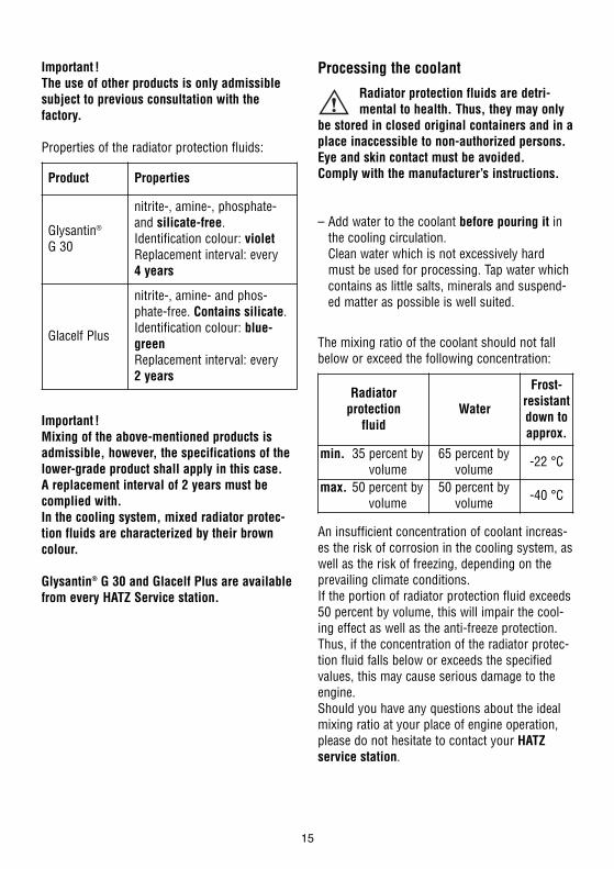
Properties of the radiator protection fluids:
Important !Mixing of the above-mentioned products is admissible, however, the specifications of thelower-grade product shall apply in this case.A replacement interval of 2 years must becomplied with.In the cooling system, mixed radiator protec-tion fluids are characterized by their browncolour.
Glysantin® G 30 and Glacelf Plus are availablefrom every HATZ Service station.
Product Properties
Glysantin®
G 30
nitrite-, amine-, phosphate-and silicate-free.Identification colour: violetReplacement interval: every 4 years
Glacelf Plus
nitrite-, amine- and phos-phate-free. Contains silicate.Identification colour: blue-greenReplacement interval: every 2 years
Processing the coolant
Radiator protection fluids are detri-mental to health. Thus, they may only
be stored in closed original containers and in aplace inaccessible to non-authorized persons.Eye and skin contact must be avoided. Comply with the manufacturer’s instructions.
– Add water to the coolant before pouring it inthe cooling circulation.Clean water which is not excessively hardmust be used for processing. Tap water whichcontains as little salts, minerals and suspend-ed matter as possible is well suited.
The mixing ratio of the coolant should not fallbelow or exceed the following concentration:
An insufficient concentration of coolant increas-es the risk of corrosion in the cooling system, aswell as the risk of freezing, depending on theprevailing climate conditions. If the portion of radiator protection fluid exceeds50 percent by volume, this will impair the cool-ing effect as well as the anti-freeze protection.Thus, if the concentration of the radiator protec-tion fluid falls below or exceeds the specifiedvalues, this may cause serious damage to theengine. Should you have any questions about the idealmixing ratio at your place of engine operation,please do not hesitate to contact your HATZservice station.
Radiator protection
fluidWater
Frost-resistantdown toapprox.
min. 35 percent byvolume
65 percent byvolume -22 °C
max. 50 percent byvolume
50 percent byvolume -40 °C
15

Note:As the concentration of the corrosion- and anti-freeze protection fluid deteriorates long-term, itmust be checked yearly using a commercial an-tifreeze tester. If the concentration is too low, nomatter at which service interval, the coolantmust be replaced as described in Chapter 5.6.1.
Filling the cooling system
Work on the cooling system must not be performed while the engine is warm - risk of scalding !The cooling system is pressurized.
13
– Open cap 1.
– Pour in coolant until the level reaches the MAXmark on the expansion tank.
– Tighten cap 1 by hand.
– After the engine has warmed up, check coolantlevel again. When the engine is at a standstilland has cooled down, the coolant level mustbe visible between the tank’s MIN and MAXmarks; if the engine is warm, the level may beslightly above the MAX mark.
– Check cooling system for leakage; if necessary, re-tighten hose clamps.
Add coolant
While the engine is warm, the cap ofthe expansion tank must not be opened
Risk of scalding. The cooling system is pres-surized.
– First stop the engine and allow it to cool down.Then put a piece of cloth over cap 1 of the ex-pansion tank and open cap carefully (Fig. 13).
– Add coolant until the level is between the MINand the MAX mark (Fig. 13).
– Tighten cap 1 by hand.
16

4.1.3. Fuel
Only refuel when engine is stopped.Never refuel close to open flames or
flammable sparks, don’t smoke. Use only purefuel and clean replenishing vessels. Don’t spillthe fuel.
14
Pos. 1 = Fuel feed linePos. 2 = Fuel return line
All diesel fuels sold as fuel and complying withthe following minimum specification can beused:
EN 590 orBS 2869 A1 / A2 orASTM D 975 -1D / 2D
Low temperature resistanceAt low temperatures, the viscosity of Diesel fuelincreases. This may result in clogging of the fuelsystem. Thus, winter fuel must be used at out-side temperatures below 0 °C, or petroleummust be added in time.
Bleeding the injection system
Air may enter into the injection system if the fueltank is completely emptied or while the primaryfuel filter or the fuel filter are replaced. To bleed the system, proceed as described be-low, depending on whether the fuel tank isarranged in HIGH position above the fuel supplypump, or in LOW position below the fuel supplypump:
Fuel tank HIGH
– Fill fuel tank completely with diesel fuel.
– Start the engine as described in Chapter 4.2.
Note:The fuel system is bled automatically when theengine is started. To this effect, starting maytake longer than usual.To save the starter and the battery, do not actuate the starter continuously for more than15 to 20 seconds at a time. Make pauses of approx. 1 minute between the various startingattempts. Should the engine fail to start even atthe 2nd attempt, locate and eliminate the trouble(Chapter 6).
Lowest ambienttemperature when
starting, in °C
Paraffin content for:Summer
fuelWinter
fuel0 up to –10
–10 up to –15–15 up to –20–20 up to –30
20 %30 %50 %
–
––
20 %50 %
17

Fuel tank LOW
If the fuel tank is located at an even lower level,a manual fuel pump or an electrical supply pumpmust be used for bleeding.
Models with manual fuel pump
15
– Place a suitable vessel under the filter to trapescaping fuel.
– Open the vent screw 1 by approx. one turn.
16
– Compress and release rubber ball repeatedly,until fuel escapes from the vent screw 1.
– Close vent screw 1, then actuate rubber ballanother two times.
1
– Start the engine as described in Chapter 4.2.
Models with electrical supply pump
– With this model, first turn the starter key toposition I and wait for approx. one minute,Chapter 4.2.2. During this waiting time, the fuel system is largely bled by means of theelectrical supply pump.
– Start the engine as described in Chapter 4.2.
4.2. Starting the engine
Do not run the engine in closed or in-sufficiently ventilated rooms – danger
of poisoning ! Before the engine is started, al-ways make sure that nobody is in the dangerarea (moving parts on engine or machinery)and that all safety guards are in place.
17
Never use any spray starting aids.
050 145 00
18

4.2.1. Preparations for starting
– If possible, disengage the engine from anydriven equipment. The auxiliary equipmentshould always be placed in neutral.
18
– Set speed control lever to a position between1/2 START and max. START, according to re-quirements. Selecting a lower engine speedwill reduce smoke when starting.
4.2.2. Electric starter
To save the starter and the battery, do not actuate the starter continuously for more than15 to 20 seconds at a time. Make pauses of approx. 1 minute between the various startingattempts. Should the engine fail to start even atthe 2nd attempt, locate and eliminate the trouble(Chapter 6).
19
– Insert the key to its stop and turn it toposition I.
– Battery charge pilot lamp 2 and oil pressure warning 3 must light up.
– Turn starter key to position II.
– As soon as the engine runs, release the starterkey. It must return to position I by itself andremain in this position during operation. The battery charge pilot lamp and oil pressurewarning must go out immediately after start-ing. Indicator light 1 is on when the engine isin operation, Fig. 19.
– The air cleaner maintenance indicator 5 onlygoes on during operation to show that the aircleaner needs cleaning or replacement (Fig. 19, Chapter 5.4.3).
19

– The engine temperature indicator 4 goes on assoon as the coolant becomes inadmissibly hot.Stop the engine immediately and trace andeliminate the cause of the problem, Chap. 6.
– Always turn the starter key back to position 0before re-starting the engine. The repeat lockin the ignition lock prevents the starter motorfrom engaging and possibly being damagedwhile the engine is still running.
Important !If a start protection module is installed, thestarter key has to be returned to position 0 forat least 8 seconds if the engine has failed tostart before a further attempt to start the enginecan be made.
Preheating device with automatic heating timer (optional equipment)
The preheating light 6 lights up additionally attemperatures below 0° centigrade (Fig. 19).
– After the light has gone out, start the enginewithout delay.
Automatic electrical shutdown system(optional equipment)
This is characterized by a brief flashing of all pilot lamps once the starter key has been turnedto position I, figure 19.
Important !If the engine cuts out immediately after startingor switches off by itself during operation, a monitoring element in the automatic shutdownsystem has tripped. The corresponding indicatorlight (Fig. 19, positions 2 - 4) will come on. After the engine has stopped, the indicator re-mains lit for another approx. 2 minutes. The electrical device then switches off automatically. The display lights up again after the starter keyhas been turned back to position 0, and then toposition I again.Trace and eliminate the cause of the operatingfault before trying to restart the engine(see Chapter 6).
The indicator light goes out when the engine isnext started.
Even with automatic shutdown monitoring the oil level must be checked every 8 – 15 operating hours (Chapter 5.2.1. and 5.2.5.).
20

4.3. Stopping the engine
If operation of the engine is interruptedfor any reason, or at the end of theworking day, the starter key should bekept out of reach of unauthorised per-sons.
Stop via engine speed setting lever
20
– Move the speed adjustment lever back to the STOP position. The engine cuts out.
Stop via the stop lever (optional equipment)
21
– Press the stop lever down towards STOP andhold it until the engine has come to a stand-still.
When the engine is not running any longer, release stop lever. The stop lever is returnedautomatically to its operating position STARTvia a spring (Fig. 21).
22
The charge 2 and oil pressure pilot lamps 3come on.
– Turn the starter key to the 0 position and pullit out. The pilot lamp lights must then go out.
23
Engines equipped with stop solenoid can alsobe stopped by turning the starter key back to position 0.
3
2
6
21

5. MaintenanceOnly carry out maintenance work with the engine switched off.For handling and disposal of used oil, coolant, filters and cleaning agents, comply with
the statutory regulations. Unauthorized access to the starter key must be prevented. Disconnectthe negative battery terminal. When maintenance work has been completed, check that all toolshave been removed from the engine and all protective guards fitted again.Before starting the engine, ensure that there are no persons in the danger area close to the en-gine or equipment.
5.1. Maintenance chart
22
Maintenance interval Maintenance work required Chap.
8-15
Every 8 – 15 operating hours, or before each daily start-up
• Check oil level.• Check combustion air intake area.• Check air cleaner maintenance indicator.• Check radiator fins for contamination.• Check coolant level.
5.2.1.5.2.2.5.2.3.5.2.4.5.2.5.
250Every 250operating hours
• Change engine oil.• Check for contamination of primary fuel filter,
renew if necessary.• Check water trap on the fuel filter.• Clean the radiator fins.• Check screw connections.• Check the Vee belt (optional equipment).
5.3.1.
5.4.1.5.3.2.5.3.3.5.3.4.5.3.5.
500 Every 500operating hours
• Replace primary fuel filter.• Replace the engine oil filter.• Maintenance of air cleaner.
5.4.1.5.4.2.5.4.3.
1000 Every 1000operating hours • Renew the fuel filter. 5.5.1.
Every 2 – 4 years• Replacement of coolant.
(every 2 years in case Glacelf Plus is used)(every 4 years in case Glysantin® G 30 is used)
5.6.1.

24
The maintenance scheme shown above is sup-plied with every engine. This stick-on labelshould be provided in an easily visible positionon the engine. However, the maintenance inter-vals are subject to maintenance chart shown inthis chapter.
For new or reconditioned engines, the followingmust always be carried out after first 50 operat-ing hours:
– Replace engine oil and oil filter, Chap. 5.3.1.and 5.4.2.
– Examine screw connections, Chap. 5.3.4.
For short operating periods: replace engine oiland oil filter after 12 months at the latest,regardless of the number of operating hours.
23

5.2. Maintenance every 8 - 15operating hours
5.2.1. Check engine oil level
When checking the oil level, the engine shouldbe standing level, and must not be running.
– Remove any dirt in the dipstick area.
25
– For oil level inspection, remove the dipstickand wipe it dry using a lint-free, clean piece ofcloth; then insert it to its stop and pull it outagain.
– Check the dipstick oil level and, if necessary,add oil to the max. mark, Chapter 4.1.1.
Attention !If the engine is operated while the oil level is below the min. mark, it will be damaged.
5.2.2. Check combustion air intake area
Severe contamination is a sign that there arelarge amounts of dust in the atmosphere andthe air cleaner maintenance intervals should bereduced, Chapter. 5.4.3.
26
27
– Check air intake port 1 – depending on version – for coarse contamination, such asleaves, lots of dust etc., if necessary, clean(Fig. 26 and 27).
24

28
– In case of models with cyclone precleaner,check the dust ejector valve for free passage; if necessary, remove deposited dust by com-pressing the valve.
5.2.3. Check air cleaner maintenanceindicator (optional equipment)
29
– Increase the engine speed briefly to maximumlevel and watch out for the pilot lamp 5 to goon. When it does go on, check the dry aircleaner, Chapter 5.4.3.
5.2.4. Check radiator fins for contamination
Serious contamination means that the mainte-nance intervals must be shorted appropriatelydue to excessive amounts of dust.
30
– Check radiator fins for coarse contamination,such as leaves, lots of dust etc., if necessary,clean them (Chapter 5.3.3.).
Attention !Seriously contaminated radiator fins may resultin engine overheating.
5.2.5. Check coolant level
31
MAX
25

– When the engine is at a standstill and hascooled down, the coolant level must be visiblebetween the tank’s MIN and MAX marks; if theengine is warm, the level may be slightlyabove the MAX mark (Fig. 31).
Loss of coolant
Work on the cooling system must notbe effected while the engine is warm –risk of scalding !The cooling system is pressurized.
In most cases, loss of coolant is due to leakagein the cooling system.
– In this case, check the cooling system for leak-age and eliminate the reason immediately – incase of doubt, consult the HATZ Service.In case of leaky hose connections, re-tightenthe hose clamps.
Note:If the cooling system is perfectly tight, loss onlyoccurs if the coolant is boiling and thus ispressed out of the cooling system via the cap onthe expansion tank.This may be due to contamination in the radiatorfin area (Chapter 5.2.4) or to engine overload.
Add coolant
– refer to Chapter 4.1.2.
5.3. Maintenance every 250operating hours
5.3.1. Change engine oil
The engine must be standing level and beswitched off.Only change the oil when the engine is warm.
Danger of scalding from hot oil ! Trap the old oil and dispose of it inaccordance with local legislation.
32
– Take out oil drain plug 1 and allow the oil todrain completely. Possible draining positions,refer to Chapter 2.
– Clean the oil drain plug 1, fit a new washer 2,insert and tighten.
– Add engine oil, Chapter 4.1.1.
5.3.2. Check water trap
The water trap inspection interval depends exclusively on the water contained in the fueland on the care applied in refuelling. It may beadmissible to extend the intervals, or it may benecessary to considerably shorten the intervals.
26

33
– Release the drain plug 1 and collect the liquidin a transparent vessel.If the drain plug is not easily accessible, an ex-tension piece of hose can be slipped on theplug.
– If an insufficient amount of liquid leaves thetank, release additionally plug 2.
As water is heavier than diesel fuel, first the water, then the fuel will escape. This is indicatedby the clearly visible separating line.
– If finally only fuel leaves through the port, thedrain plug 1 can be closed again.
– Subsequently, re-tighten plug 2.
Note:If starting appears difficult, bleed the injectionsystem (Chapter 4.1.3).
1
25.3.3. Clean the radiator fins
For cleaning, the engine must be at astandstill and have cooled down.
Important !The delicate radiator fins must never be cleanedusing tools, such as a screw-driver or a spatula.Deformed radiator fins or radiator leakage mayreduce the radiator performance.
– Place a vessel below the radiator to collect anycontamination.
Dry contamination
34
– Blow-clean radiator fins – depending on thedegree of soiling – either using compressedair or rinse them using a water jet (first fromitem 1, then from item 2).Do not use a high-pressure jet.
Damp or oily contamination
– Spray-coat the whole area with an appropriatecleaning solution according to the manufactur-er’s specification, and subsequently clean bymeans of a water jet. Do not use a high-pres-sure jet.
Note:Do not use gasoline or acidic cleaning agents.
– Determine the cause of oiling and eliminateleakage.
MAX
27

5.3.4. Check screw connections
– Check the tightness of all threaded connec-tions and take up slack if necessary, providedthat these can be reached during maintenancework.
35
36
The adjusting screws at the enginegovernor and on the injection system
are sealed with lacquer and are not to be tightened or adjusted, Figs. 35 and 36.
5.3.5. Check the Vee belt(optional equipment)
– Check the Vee belt over its entire circumferencefor cracks or damage; if necessary, replace.
37
– Check the belt tension by pressing it downwith your thumb; if necessary, re-tighten.
Re-tighten the Vee belt
38
– Release the screws 1-3 and pull three-phasealternator 4 outwards.
– Re-tighten the screws and check the belt tension.
28

Replace the Vee belt
39
– Release the screws 1-3 and push three-phasealternator 4 to the inside.
– Remove Vee belt and replace it by a new one.
– Pull the three-phase alternator 4 outwards andre-tighten the screws (Fig. 38).
– Check the belt tension.
Note:Check tension of new belts once more after approx. 15 minutes of operation.
5.4. Maintenance every 500operating hours
5.4.1. Replace primary fuel filter
Note:Primary fuel filter maintenance intervals dependon the purity of the fuel used in the engine andshould be reduced to 250 hours if necessary.
Do not smoke and never bring a nakedflame near the fuel system when work-ing on it.
Important:Keep the entire area clean so that no dirt reaches the fuel.
– Place a suitable vessel under the filter to trapescaping fuel.
– Close the fuel supply line.
40
– Pull fuel supply line 1 off the primary fuel filter 2 at both sides.
– Insert the new primary fuel filter.
29

Important:When installing a new filter, note the arrow indi-cating the correct flow direction (depends onwhether the tank is mounted HIGH or LOW.The filter’s installed position (direction of flow)should be as vertical as possible.
– Open the fuel supply line.
– Check fuel filter and lines for leakage after ashort test run.
Note:If starting appears difficult, bleed the injectionsystem (Chapter 4.1.3).
5.4.2. Replace the engine oil filter
It makes sense to replace the filter cartridge simultaneously with the engine oil change.
The engine must be placed horizontally and be at a standstill.
Danger of scalding from hot oil ! Trap the old oil and dispose of it inaccordance with local legislation.
Horizontal replaceable-cartridge filter (standard equipment)
41
– Release replaceable-cartridge lubricant filter bymeans of a strap wrench or a similar tool, andremove it.
42
– Clean sealing surface 1 thoroughly.
– Slightly grease the packing ring 2 of the newreplaceable-cartridge filter.
– Turn-in replaceable-cartridge filter and tightenit by hand.
Vertical replaceable-cartridge filter (optional equipment)– Remove air cleaner cover including filter
cartridges. Chapter 5.4.3.
43
– Release replaceable-cartridge lubricant filter bymeans of a strap wrench or a similar tool.Alternately, an appropriate tool can also beslipped on the hexagon 1.
30

44
– Turn-out replaceable-cartridge filter to the ex-tent shown in the illustration. In this position,a valve releases the oil return flow into thecrankcase, whereupon the replaceable-car-tridge filter is emptied. After a waiting periodof approx. 30 seconds, the replaceable-car-tridge filter can be unscrewed completely.
45
– Clean sealing surface 1 and moulding 2 thor-oughly.
– Slightly grease the packing ring 3 of the newreplaceable-cartridge filter.
– Turn-in replaceable-cartridge filter and tightenit by hand.
– Assemble the air filter cartridges and the coverfor the air cleaner, Chapter 5.4.3.
– Replenish lubricant of the appropriate specifi-cation and viscosity until the level reaches theMAX mark of the dipstick (Chapter 4.1.1).
– After a short test run, check replaceable-cartridge filter for leakage; if necessary, re-tighten.
– Check oil level and, if necessary, replenish.
5.4.3. Maintenance of air cleaner
It makes sense to clean the filter cartridge (twoeach in case of three- and four-cylinder engines)only if the maintenance indicator signals the ne-cessity. Apart from that, the cartridge must bereplaced after a period of 500 service hours.
46
– Release the toggle-type fasteners.
31

47
– Tilt air cleaner cover forwards (arrow 1), thenlift it and remove it (arrow 2).
48
– Pull filter cartridges carefully off the filter support.
– Clean the filter support and the air cleaner cover.Make sure that dirt or other foreign mattercannot enter the engine air intake port 1.
49
– Check seal 1 and rubber pad 2 for damage, de-formation and cracks; if necessary, replace.
– The filter cartridge must either be replaced or -depending on the degree of contamination -cleaned or checked:
Cleaning the filter cartridge
Dry contamination
50
– Use compressed air to blow through the filtercartridge from the inside outwards, until nofurther dirt emerges.
Important ! The pressure must not exceed 5 bar.
32

Moist or oily contamination– Renew the filter cartridge.
Checking the filter cartridge
– Check filter cartridge’s gasket surface 1 fordamage, Fig. 50.
– Check the filter cartridge for cracks or any other type of damage to the paper filter byholding it inclined towards the light or by shining a light source through it.
Important !The slightest damage to the paper filter rulesout its being used any longer.
– Re-assemble the filter cartridge in the reverseorder of work.
51
– Make sure the filter cartridge is mounted onthe correct end.
042 746 00
52
– Position air cleaner cover at the bottom of thefilter support (arrow 1), then tilt it towards theengine (arrow 2).
53
– Before fastening the toggle-type fasteners,align the air cleaner cover on the left with thefiler support.
33

5.5. Maintenance every 1000operating hours
5.5.1. Renew the fuel filter
Note:Fuel filter maintenance intervals depend on the purity of the fuel used; reduce them to 500 hours of operation if necessary.
Do not smoke and never bring a nakedflame near the fuel system when work-ing on it.
Important !Maximum cleanliness is required to prevent dirt from entering the fuel system.Fuel particles may damage the injection system.
Replace the fuel filter
54
– Close the fuel lines at the filter housing.
55
– Place a suitable vessel under the filter to trapescaping fuel.
– Release drain plug 1 to drain the fuel.
56
– Release the fuel filter using a strap wrench ora similar tool, and remove it.
1
34
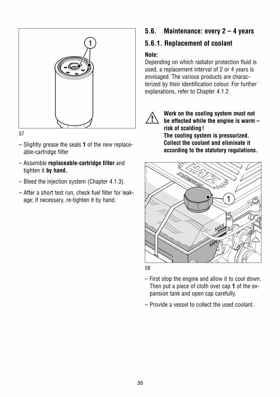
57
– Slightly grease the seals 1 of the new replace-able-cartridge filter
– Assemble replaceable-cartridge filter andtighten it by hand.
– Bleed the injection system (Chapter 4.1.3).
– After a short test run, check fuel filter for leak-age; if necessary, re-tighten it by hand.
5.6. Maintenance: every 2 – 4 years
5.6.1. Replacement of coolant
Note:Depending on which radiator protection fluid isused, a replacement interval of 2 or 4 years isenvisaged. The various products are charac-terized by their identification colour. For furtherexplanations, refer to Chapter 4.1.2.
Work on the cooling system must notbe effected while the engine is warm –risk of scalding !The cooling system is pressurized.Collect the coolant and eliminate it according to the statutory regulations.
58
– First stop the engine and allow it to cool down. Then put a piece of cloth over cap 1 of the ex-pansion tank and open cap carefully.
– Provide a vessel to collect the used coolant.
35

59
– Unscrew the drain plug 1 from the engine anddrain coolant.
60
– Subsequently unscrew the drain plug 1 fromthe radiator and drain the coolant as well.
– Turn-in drain plugs 1 with new packing ring 2and tighten them (Fig. 59 and 60).
– Fill the cooling system (Chapter 4.1.2.).
36

37
6. Malfunctions – Causes – Remedies
Malfunction Possible causes Remedy Chap.
6.1. Engine will not startor start is delayed, although itcan be turned overwith the starter.
At low temperatures.
Speed control lever is in stop oridle position.Stop lever in stop position.
No fuel reaching injection pump.
Compression too low:-Valve clearances incorrect
-Cylinder bore and/or piston ringwear
Unit Injector System not operating correctly
Lower starting temperature limitexceeded.
Machinery not uncoupled.
Defective preheating system(optional equipment).
Fuel highly viscous due to inadequate resistance to low temperatures.
Set lever to „START“-position
Add. fuel.Bleed the injection system.Check entire fuel supply systemcarefully.If no fault is found:-supply line to engine-primary fuel filter-Check the fuel filter.
See workshop manual.
See workshop manual.
See workshop manual.
Operate preheating system(optional equipment).
Disengage engine from machineryor equipment if possible.
See workshop manual.
Check that clear fuel - i.e. withoutturbidity - leaves from the discon-nected fuel supply line. If the fuelis highly viscous, either warm upthe engine or drain the entire fuelsupply system.Pour in a temperature-resistant fuel mix.
4.2.1.
4.1.3.4.1.3.
5.4.1.5.5.1.
4.2.2.

38
Malfunction Possible causes Remedy Chap.
At low temperatures.
If equipped with astop solenoid or automatic electricalshutdown system (optional equipment)
6.2.Engine fires but doesnot run.
With automatic electrical shutdowninstalled (optional equipment)
6.3.Starter motor doesnot operate or engine does not turnover.
Starting speed too low:-Engine oil is too viscous.
-Battery charge is insufficient.
Solenoid faulty and/or fault in theelectrical system.
Speed control lever not moved far enough towards START.
Equipment not disengaged.
Primary fuel filter or fuel filterclogged.
Fuel supply interrupted.
One of the automatic shutdown’smonitoring elements has initiateda stop signal.(See also Chapter 6.4.).
Fault in the electrical system:- Battery and/or other cables
incorrectly connected.- Cable connections loose and/or
oxidised.- Battery faulty and/or flat.- Starter faulty.- Faulty relays, monitoring
elements, etc.
Change lubricating oil and refillwith a different grade of oil.
Check the battery; consult a spe-cialist workshop if necessary.
See workshop manual.
Move lever to START position.
Disengage engine from equipmentif possible.
Replace filter.
Check all fuel supply componentssystematically.
Locate the responsible monitoringelement and clear the fault, or con-tact a HATZ service station.
Check electrical system and itscomponent. See also the workshop manual.
5.3.1.4.1.1.
4.2.1.
5.4.1.5.5.1.

39
Malfunction Possible causes Remedy Chap.
6.4.Engine stops by itself during operation.
With automatic electrical shutdowninstalled (optional equipment)
6.5.Engine output andspeed both drop.
Fuel supply interrupted-Tank has run empty.-Primary fuel filter or fuel filterclogged.
Mechanical faults
One of the automatic shutdown’smonitoring elements has initiateda stop signal.
Monitoring element for:-oil pressure too low-engine temperature too high
-AC generator or three-phase alternator (optional equipment)faulty.
Malfunction signal from overvolt-age and polarity reversal protec-tion in voltage regulator:-Battery and/or other cable con-nections incorrectly connected.
-Cable connections loose.
Fuel supply interrupted:-Tank has run empty.-Primary fuel filter or fuel filterclogged.
-Tank insufficiently ventilated.
-Pipe connections leaky.
-Speed control lever does notremain in desired position.
Add fuel.Change fuel filter.
Contact a HATZ service station.
Locate the responsible monitoringelement and clear the fault, or con-tact a HATZ service station.
-Check lubricating oil supply.-Radiator fins soiled or coolingsystem function otherwise im-paired.
-Coolant level.-Check belt tension (only in caseof models with belt-driven fan).
See workshop manual.
Check electrical equipment and thecomponents thereof.
Add fuel.Replace filter.
Ensure sufficient ventilation oftank.Check pipe screw couplings forleakage.
Lock the lever into position.
4.1.3.5.4.1.5.5.1.
4.2.2.
5.2.1.5.2.4.
5.2.5.
5.3.5.
4.1.3.5.4.1.5.5.1.

40
Malfunction Possible causes Remedy Chap.
6.6.Engine output and speed fall, black smoke from exhaust.
6.7.Engine gets very hot.Engine temperaturepilot lamp goes on.
Air cleaner contaminated.
Valve clearances incorrect.
Unit Injector System not functioning.
Too much lubricating oil in engine.
Insufficient cooling effect:-Radiator fins soiled.
-Loss of coolant.
-Vee belt broken or slack (only incase of models with belt-drivenfan).
-Engine overloaded.
Clean or renew the air cleaner.
See workshop manual.
See workshop manual.
Drain off lubricating oil as far asupper mark on dipstick.
Clean the radiator fins.
Check cooling system for leakageand eliminate cause - in case ofdoubt, contact the HATZ Servicestation. Subsequently, replenishcoolant.
Check the Vee belt
Reduce load.
5.4.3.
5.3.1.
5.3.3.
4.1.2.
5.3.5.

7. Work on the electricalsystem
Batteries generate explosive gases.Keep them away from naked flame and
sparks which could cause them to ignite. Do not smoke. Protect eyes, skin and clothes against the corrosive battery acid. Pour clear water overacid splashes immediately. In case of emergency call a doctor.Do not place any tools on top of the battery.
Always disconnect the negative (–) terminal of the battery before working on the electricalsystem.
– Do not confuse the positive (+) and negative (–) terminals of the battery.
– When fitting the battery, first connect the positive lead, then the negative lead.Negative terminal to ground = engine case.
– When removing, first disconnect the negativelead, then the positive lead.
– Always take care to avoid short-circuits andearth (ground) contact of live cables.
– If malfunctions occur, first of all check that cable connections make good contact.
– Replace a failed pilot lamp without delay.
– Do not remove the starter key while the engine is running.
– Do not disconnect the battery while the en-gine is running. Electric voltage peaks cancause damage to electronic components.
– Do not splash electrical system with water jetor pressure jet during engine cleaning.
– When carrying out welding work on the en-gine or equipment, fit the ground terminal ofthe welding equipment as close to the weldingpoint as possible and disconnect the battery.The connecting plug for the voltage regulatormust be removed.
The relevant circuit diagrams are enclosed withthe engine if it is equipped with an electrical system. Additional circuit diagrams can be supplied to order.
HATZ assumes no liability for electrical systemswhich have not been carried out acc. to HATZcircuit diagrams.
8. Storage out of use
The new engine can normally be stored dry forup to one year.In very humid climates or coastal regions, theprotective treatment is sufficient for up to about6 months.For longer periods of storage, please contactyour nearest HATZ service station.
41

SUPPLEMENTAL INFORMATIONTO THE OWNER'S MANUAL FOR 2008 AND LATER
EPA CERTIFIEDNONROAD COMPRESSION IGNITION ENGINES.
EPA EMISSION CONTROL SUPPLEMENTALWARRANTY STATEMENT AND
EMISSION-RELATED INSTALLATIONINSTRUCTIONS.
43

MAINTENANCE AND WARRANTY.
SUPPLEMENTAL INFORMATION TO THE OWNERS MANUAL FOR 2008 ANDLATER EPA CERTIFIED NONROAD COMPRESSION IGNITION ENGINES.
The following supplemental information is furnished for EPA Nonroad Compression Ignition Engines which are certified according to 40 CFR Part 89 and Part 1039.
This information contains the following specific items:
• EPA-related engine parts and engine operating conditions
• Maintenance instructions for EPA-related engine parts
• Emission control system and adjustments
• Warranty statement
• Emission-related installation instructions
ENGINE PARTS AND / OR EQUIPMENT RELATED TO EPA EXHAUSTEMISSION REGULATIONS.
Parts which are mandatory for engine operation.
The following parts as manufactured according to HATZ specifications are mandatory forengine operation which meets EPA exhaust emission regulations.
• Air cleaner housing
• Cold air duct
• Turbocharger ( including wastegate ), ducting
• Unit Injectors
• Oil filler cap
44

• PCV ( 'positive crankcase ventilation' ) connection assembly
• Exhaust manifold
• Emission Control Information Labels
Only parts manufactured by Hatz and which have passed the Hatz Quality Assurance Program are assured of meeting EPA exhaust emission regulations.
UNUSUAL OPERATING CONDITIONS.
The engine must not be operated at a load factor less than 25 % for an extended period assuch operation will cause the fuel injector to foul. If such a condition occurs, you shouldcontact the nearest HATZ authorized Service Center for necessary repairs.
The engine is designed and adjusted to operate most efficiently at the following conditions:
• Air temperature of 25° C ( 77° F)
• Atmospheric pressure of 100 kPa (14.5 psi)
• Relative humidity of 30 %
Operation of the engine at conditions other than above will affect performance and exhaust emissions. Normally the equipment manufacturer takes this into account duringthe design of the machine and your equipment will perform within specifications over awide range of climatic conditions. However if you must operate your equipment undervery unusual climatic conditions, please contact your nearest Hatz distributor for advice.
45

MAINTENANCE SCHEDULE-EPA-RELATED PARTS
The following minimum intervals are being adopted for adjustment, cleaning, repair, orreplacement of following components:
At 1,500 hours, and 1,500-hours intervals thereafter:• Fuel injector tips (cleaning only)
At 3,000 hours, and 3,000-hours intervals thereafter:• Fuel injector
The exhaust quality of the engines can be influenced by the execution (the quality of execution) of above described maintenance work.
Therefore, the maintenance work has to be carried out by a qualified workshop.Hatz authorised workshops, for example, are qualified workshops.
Hatz Diesel of America will give you respective addresses, if required.
EMISSION CONTROL SYSTEM AND ADJUSTMENTS.
The emission control system for this engine is EM (Engine Modification). No adjustments are needed or possible.
46

EPA EMISSION CONTROL WARRANTY STATEMENT
YOUR WARRANTY RIGHTS AND OBLIGATIONS.
Motorenfabrik Hatz GmbH & Co. KG warrants the emission control system on your engine for the periods of time listed below provided there has been no abuse, neglect orimproper maintenance of your engine.
Your emission control system includes:
• Air cleaner housing
• Cold air duct
• Turbocharger ( including wastegate ), ducting
• Unit Injectors
• Oil filler cap
• PCV ( 'positive crankcase ventilation' ) connection assembly
• Exhaust manifold
• Emission Control Information Labels
Where a warrantable condition exists, Motorenfabrik Hatz will repair your engine at nocost to you including diagnosis, parts and labor.
47

MANUFACTURERS WARRANTY COVERAGE:
The 2008 and later EPA certified nonroad compression ignition engines are warranted for1500 hours of operation or two years of use, whichever first occurs.
If any emission related part on your engine is defective, the part will be repaired or replaced by Motorenfabrik Hatz.
OWNERS WARRANTY RESPONSIBILITIES:
• As the engine owner, you are responsible for the performance of the required maintenance listed in your owner's manual. Motorenfabrik Hatz recommends that youretain all receipts covering maintenance on your engine, but Motorenfabrik Hatz cannotdeny warranty solely for the lack of receipts or for your failure to ensure the performance of all scheduled maintenance.
• As the engine owner, you should be aware, however, that Motorenfabrik Hatz may deny you warranty coverage if your engine or a part has failed due to abuse, neglect,improper maintenance or unapproved modifications.
• You are responsible for presenting your engine to a Motorenfabrik Hatz authorizedservice center as soon as a problem exists. The warranty repairs should be completed ina reasonable amount of time, not to exceed 30 days.
If you have any questions regarding your warranty rights and responsibilities, you shouldcontact HATZ DIESEL OF AMERICA, Inc. at (262)-544-0254.
HATZ DIESEL SUPPLEMENTAL WARRANTY FOR 2008 AND LATER EPACERTIFIED ENGINES.
48

PARTS WITH SUPPLEMENTAL LIMITED WARRANTY.
The following limited warranty is supplemental to the standard HATZ DIESEL LIMITEDENGINE WARRANTY and covers 2008 and later EPA certified engines and applies tothe following exhaust emission-related components:
• Air cleaner housing
• Cold air duct
• Turbocharger ( including wastegate ), ducting
• Unit Injectors
• Oil filler cap
• PCV ( 'positive crankcase ventilation' ) connection assembly
• Exhaust manifold
• Emission Control Information Labels
49

SUPPLEMENTAL LIMITED WARRANTY.
Hatz Diesel of America, Inc. hereinafter referred to as “HATZ” warrants each of theabove-listed parts when installed in a new engine sold by Hatz to be free from defects inmaterial and workmanship under normal use and service, only under the named warrantycoverage conditions, after the date of delivery to the original retail purchaser and Hatzwill at their option, repair or replace at Hatz's sales headquarters, or at a point designatedby Hatz, any part or parts which shall appear to the satisfaction of Hatz upon inspection atsuch point, to have been defective in material or workmanship.
• Any warranted part which is scheduled for replacement as required maintenance is warranted for the period of time up to the first scheduled replacement point for thatpart.
• Any replacement part which is equivalent in performance and durability may be used innon-warranty maintenance or repairs and will not reduce the overall engine warrranty obligations of Hatz. However, Hatz is not responsible for failure of such replacementparts or failure of any other parts directly caused by failure of such replacement parts.
• This warranty does not obligate Hatz to bear any transportation charges in connectionwith the repair or replacement of defective parts. This warranty is transferrable to subsequent owners, only under the named warranty coverage conditions.
• In order to obtain service under this warranty, the retail purchaser should contact HatzDiesel of America, Inc. at (262)-544-0254 for information and the nearest service center. The retail purchaser will not be charged for diagnostic labor which leads to the determination that a warranted part is defective, nor for the repair or replacement of warranted parts if the work is performed at an authorized Hatz service center. If other engine components are damaged due to a failure of the above-listed warranted parts still under warranty, these other engine components will also be repaired or replaced at no charge.
• This warranty shall not apply to any engine which shall have been installed or operated in a manner not recommended by Hatz, nor to any engine which shall havebeen repaired, altered, neglected, or used in any way which, in the opinion of Hatz, adversely affects its performance, nor to any engine in which parts not authorized byHatz have been used, which parts or the use of which have damaged or caused defectsin or otherwise adversely affected the engine or its performance, nor to normal maintenance service or replacement of normal service items.
Hatz reserves the right to modify, alter, and improve any engine or parts without incurringany obligation to replace any engine or parts previously sold with such modified, altered,or improved engine or parts.
50
EMISSION-RELATED INSTALLATION INSTRUCTIONS
“Failing to follow these instructions when installing a certified engine in a piece of nonroad equipment violates federal law (40CFR1068.105(b)), subject to fines or otherpenalties as described in the Clean Air Act.”
“If you install the engine in a way that makes the engine's emission control informationlabels hard to read during normal engine maintenance, you must place duplicate labels onthe equipment.”
EQUIPMENT-LABELLING REQUIREMENTS: FUEL LABEL (Chapter 3.5)
The fuel label has to be permanently attached to the equipment.In case of an engine mounted fuel tank, every engine is equipped with an additional fuellabel.Otherwise, there are two loose fuel labels available with the engine.
If the original fuel label is not readily visible after the engine is installed in the equipmentthen the second loose fuel label must be attached on the equipment in such a manner thatit is readily visible to an average person.
51

INSTRUCTIONS ON THE INSTALLATION OF THE EXHAUST SYSTEM
Following are the instructions to properly install the exhaust system and related components consistent with the EPA emission regulation requirements.
Electrical starter
The electrical starter is fitted in connection with washers, hex.-nuts and Allen screws.
Preparations:• Disconnect the negative pole 1 of the battery.
Dismantling:• Remove in numerical sequence 2...7.
Assembly:• Assemble in reverse sequence.
52
2W35 · 3W35 · 4W35 (T)

Exhaust-silencers
The exhaust silencer is fitted in connection with washers, hex.-nuts, metal bellows and aprotection plate.
Dismantling:• Remove in numerical sequence 1...7.
Assembly:• Assemble in reverse sequence.
53
2W35 · 3W35 · 4W35 (T)

SAMPLING OF EXHAUST EMISSIONS
After the engine is installed in the equipment and placed in service, the sampling of exhaust emissions can be performed in a way that prevents diluting the exhaust samplewith ambient air as follows:
Specification 1: Adding a 20-centimeter linear extension to the exhaust pipe
54
Version 1

Specification 2: Adding a 20-centimeter bended extension to the exhaust pipe
55
Version 2
Engine type Ø d (mm)Version 1
HATZ-Ident. Nr.Version 2
HATZ-Ident. Nr.Clamp
HATZ-Ident. Nr.2W35 38 830 857 000 830 858 00 037 409 003W35 38 830 857 000 830 858 00 037 409 004W35 (T) 38 830 857 000 830 858 00 037 409 00


SUPPLEMENTAL INFORMATIONTO THE OWNER´S MANUAL
FOR 2008 AND LATERCALIFORNIA REGULATIONS FOR
HEAVY-DUTY OFF-ROAD ENGINES.
CALIFORNIA EMISSION CONTROLWARRANTY STATEMENT AND
EMISSION-RELATED INSTALLATION INSTRUCTIONS.
57

MAINTENANCE AND WARRANTY.
SUPPLEMENTAL INFORMATION TO THE OWNER´S MANUAL FOR 2008AND LATER CALIFORNIA REGULATIONS FOR HEAVY-DUTY OFF-ROADENGINES.
The following supplemental information is furnished for California Heavy-Duty Off-RoadEngines.
This information contains the following specific items:
• CARB-related engine parts and engine operating conditions
• Maintenance instructions for CARB-related engine parts
• Emission control system and adjustments
• Warranty statement
• Emission-related installation instructions
ENGINE PARTS AND / OR EQUIPMENT RELATED TO CARB EXHAUSTEMISSION REGULATIONS.
Parts which are mandatory for engine operation.
The following parts as manufactured according to HATZ specifications are mandatory forengine operation which meets CARB exhaust emission regulations.
• Air cleaner housing
• Cold air duct
• Turbocharger ( including wastegate ), ducting
• Unit Injectors
• Oil filler cap
• PCV ( 'positive crankcase ventilation' ) connection assembly
58

• Exhaust manifold
• Emission Control Information Labels
Only parts manufactured by Hatz and which have passed the Hatz Quality Assurance Program are assured of meeting CARB exhaust emission regulations.
UNUSUAL OPERATING CONDITIONS.
The engine must not be operated at a load factor less than 25 % for an extended period assuch operation will cause the fuel injector to foul. If such a condition occurs, you shouldcontact the nearest HATZ authorized Service Center for necessary repairs.
The engine is designed and adjusted to operate most efficiently at the following conditions:
• Air temperature of 25° C ( 77° F)
• Atmospheric pressure of 100 kPa (14.5 psi)
• Relative humidity of 30 %
Operation of the engine at conditions other than above will affect performance and exhaust emissions. Normally the equipment manufacturer takes this into account duringthe design of the machine and your equipment will perform within specifications over awide range of climatic conditions. However if you must operate your equipment undervery unusual climatic conditions, please contact your nearest Hatz distributor for advice.
MAINTENANCE SCHEDULE-CARB-RELATED PARTS.
The following minimum intervals are being adopted for adjustment, cleaning, repair, orreplacement of following components:
At 1,500 hours, and 1,500 hours intervals thereafter:
• Fuel injector tips (cleaning only)
At 3,000 hours, and 3000 hours intervals thereafter:
• Fuel Injectors
59

The exhaust quality of engines can be influenced by the execution (the quality of execution) of above described maintenance work.
Therefore, the maintenance work has to be carried out by a qualified workshop. Hatz authorised workshops, for example, are qualified workshops.Hatz Diesel of America will give you respective addresses, if required.
EMISSION CONTROL SYSTEM AND ADJUSTMENTS.
The emission control system for this engine is EM (Engine Modification). No adjustments are needed or possible.
CALIFORNIA EMISSION CONTROL WARRANTY STATEMENT.
YOUR WARRANTY RIGHTS AND OBLIGATIONS.
The California Air Resources Board and Motorenfabrik Hatz GmbH & Co. KG arepleased to explain the emission control system warranty on your 2008 and laterengine. In California, new heavy-duty off-road engines must be designed, built, andequipped to meet the State’s stringent anti-smog standards. The Motorenfabrik HatzGmbH & Co. KG must warrant the emission control system on your engine for the periods of time listed below provided there has been no abuse, neglect or improper maintenance of your engine.
Your emission control system may include parts such as the fuel-injection system and the air induction system. Also included may be hoses, belts, connectors and other emission-related assemblies.
Where a warrantable condition exists, the Motorenfabrik Hatz GmbH & Co. KG will repair your heavy-duty off-road engine at no cost to you including diagnosis, parts, andlabor.
60

MANUFACTURER´S WARRANTY COVERAGE.
The 2008 and later heavy-duty off-road engines are warranted for 1500 hours of operation or two years of use, whichever first occurs.If any emission-related part on your engine is defective, the part will be repaired or replaced by Motorenfabrik Hatz GmbH & Co. KG.
OWNER´S WARRANTY RESPONSIBILITIES.
• As the heavy-duty off-road engine owner, you are responsible for the performance ofthe required maintenance listed in your owner’s manual. Motorenfabrik Hatz GmbH & Co. KG recommends that you retain all receipts coveringmaintenance on your heavy-duty off-road engine, but Motorenfabrik Hatz GmbH & Co.KG cannot deny warranty solely for the lack of receipts or for your failure to ensure theperformance of all scheduled maintenance.
• As the heavy-duty off-road engine owner, you should however be aware that Motorenfabrik Hatz GmbH & Co. KG may deny you warranty coverage if your heavy-duty off-road engine or a part has failed due to abuse, neglect, improper maintenance or unapproved modifications.
• Your engine is designed to operate on low sulfur diesel fuel or ultra-low sulfur dieselfuel only. Use of any other fuel may result in your engine no longer operating in compliance with California’s emissions requirements.
• You are responsible for initiating the warranty process. The ARB suggests that youpresent your heavy-duty off-road engine to a Motorenfabrik Hatz authorised dealer assoon as a problem exists. The warranty repairs should be completed by the dealer as expeditiously as possible.
If you have any questions regarding your warranty rights and responsibilities, you shouldcontact Hatz Diesel of America, Inc. at (262)-544-0254.
61

HATZ DIESEL SUPPLEMENTAL WARRANTY FOR 2008 AND LATER CALIFORNIA CERTIFIED HEAVY-DUTY OFF-ROAD ENGINES.
PARTS WITH SUPPLEMENTAL LIMITED WARRANTY.
The following limited warranty is supplemental to the standard HATZ DIESEL LIMITEDENGINE WARRANTY and covers 2008 and later California certified Heavy-Duty off-road engines and applies to the following exhaust emission-related components:
• Air cleaner housing
• Cold air duct
• Turbocharger ( including wastegate ), ducting
• Unit Injectors
• Oil filler cap
• PCV ( 'positive crankcase ventilation' ) connection assembly
• Exhaust manifold
• Emission Control Information Labels
62

SUPPLEMENTAL LIMITED WARRANTY.
Hatz Diesel of America, Inc. hereinafter referred to as "HATZ" warrants each of theabove-listed parts when installed in a new engine sold by Hatz to be free from defects inmaterial and workmanship under normal use and service, for a period of twenty-four (24)months after the date of delivery to the original retail purchaser and Hatz will at their option, repair or replace at Hatz's sales headquaters, or at a point designated by Hatz, anypart or parts which shall appear to the satisfaction of Hatz upon inspection at such point,to have been defective in material or workmanship.
• Any warranted part which is scheduled for replacement as required maintenance is warranted for the period of time up to the first scheduled replacement point for thatpart.
• Any replacement part which is equivalent in performance and durability may be used innon-warranty maintenance or repairs and will not reduce the overall engine warrrantyobligations of Hatz. However, Hatz is not responsible for failure of such replacementparts or failure of any other parts directly caused by failure of such replacement parts.
• This warranty does not obligate Hatz to bear any transportation charges in connectionwith the repair or replacement of defective parts. This warranty is transferrable to sub-sequent owners within the original twenty-four (24) months time period.
• In order to obtain service under this warranty, the retail purchaser should contact HatzDiesel of America, Inc. at (262)-544-0254 for information and the nearest service center. The retail purchaser will not be charged for diagnostic labor which leads to thedetermination that a warranted part is defective, nor for the repair or replacement ofwarranted parts if the work is performed at an authorized Hatz service center. If otherengine components are damaged due to a failure of the above-listed warranted partsstill under warranty, these other engine components will also be repaired or replaced atno charge.
• This warranty shall not apply to any engine which shall have been installed or operatedin a manner not recommended by Hatz, nor to any engine which shall have been repaired, altered, neglected, or used in any way which, in the opinion of Hatz, adverse-ly affects its performance, nor to any engine in which parts not authorized by Hatz havebeen used, which parts or the use of which have damaged or caused defects in or otherwise adversely affected the engine or its performance, nor to normal maintenanceservice or replacement of normal service items.
Hatz reserves the right to modify, alter, and improve any engine or parts without incurringany obligation to replace any engine or parts previously sold with such modified, altered,or improved engine or parts.
63

EMISSION-RELATED INSTALLATION INSTRUCTIONS
“Failing to follow these instructions when installing a certified engine in a piece of nonroad equipment violates federal law (40CFR1068.105(b)), subject to fines or otherpenalties as described in the Clean Air Act.”
“If you install the engine in a way that makes the engine's emission control informationlabels hard to read during normal engine maintenance, you must place duplicate labels onthe equipment.”
EQUIPMENT-LABELLING REQUIREMENTS: FUEL LABEL (Chapter 3.5)
The fuel label has to be permanently attached to the equipment.In case of an engine mounted fuel tank, every engine is equipped with an additional fuellabel.Otherwise, there are two loose fuel labels available with the engine.
If the original fuel label is not readily visible after the engine is installed in the equipmentthen the second loose fuel label must be attached on the equipment in such a manner thatit is readily visible to an average person.
64

INSTRUCTIONS ON THE INSTALLATION OF THE EXHAUST SYSTEM
Following are the instructions to properly install the exhaust system and related components consistent with the EPA emission regulation requirements.
Electrical starter
The electrical starter is fitted in connection with washers, hex.-nuts and Allen screws.
Preparations:• Disconnect the negative pole 1 of the battery.
Dismantling:• Remove in numerical sequence 2...7.
Assembly:• Assemble in reverse sequence.
65
2W35 · 3W35 · 4W35 (T)

Exhaust-silencers
The exhaust silencer is fitted in connection with washers, hex.-nuts, metal bellows and aprotection plate.
Dismantling:• Remove in numerical sequence 1...7.
Assembly:• Assemble in reverse sequence.
66
2W35 · 3W35 · 4W35 (T)

SAMPLING OF EXHAUST EMISSIONS
After the engine is installed in the equipment and placed in service, the sampling of exhaust emissions can be performed in a way that prevents diluting the exhaust samplewith ambient air as follows:
Specification 1: Adding a 20-centimeter linear extension to the exhaust pipe
67
Version 1

Specification 2: Adding a 20-centimeter bended extension to the exhaust pipe
68
Version 2
Engine type Ø d (mm)Version 1
HATZ-Ident. Nr.Version 2
HATZ-Ident. Nr.Clamp
HATZ-Ident. Nr.2W35 38 830 857 000 830 858 00 037 409 003W35 38 830 857 000 830 858 00 037 409 004W35 (T) 38 830 857 000 830 858 00 037 409 00
CALIFORNIA
Proposition 65 Warning
Diesel engine exhaust and some of itsconstituents are known to the Stateof California to cause cancer, birthdefects, and other reproductive harm.