the case for distributed engine control in turbo-shaft ... · the case for distributed engine...
TRANSCRIPT

Dennis E. CulleyGlenn Research Center, Cleveland, Ohio
Paul J. Paluszewski and William StoreyGoodrich Engine Control Systems, North America, W. Hartford, Connecticut
Bert J. SmithAviation Applied Technology Directorate, Ft. Eustis, Virginia
The Case for Distributed Engine Controlin Turbo-Shaft Engine Systems
NASA/TM—2009-215654
September 2009
AHS 2009 080366
https://ntrs.nasa.gov/search.jsp?R=20090038710 2018-07-15T17:49:56+00:00Z

NASA STI Program . . . in Profi le
Since its founding, NASA has been dedicated to the advancement of aeronautics and space science. The NASA Scientifi c and Technical Information (STI) program plays a key part in helping NASA maintain this important role.
The NASA STI Program operates under the auspices of the Agency Chief Information Offi cer. It collects, organizes, provides for archiving, and disseminates NASA’s STI. The NASA STI program provides access to the NASA Aeronautics and Space Database and its public interface, the NASA Technical Reports Server, thus providing one of the largest collections of aeronautical and space science STI in the world. Results are published in both non-NASA channels and by NASA in the NASA STI Report Series, which includes the following report types: • TECHNICAL PUBLICATION. Reports of
completed research or a major signifi cant phase of research that present the results of NASA programs and include extensive data or theoretical analysis. Includes compilations of signifi cant scientifi c and technical data and information deemed to be of continuing reference value. NASA counterpart of peer-reviewed formal professional papers but has less stringent limitations on manuscript length and extent of graphic presentations.
• TECHNICAL MEMORANDUM. Scientifi c
and technical fi ndings that are preliminary or of specialized interest, e.g., quick release reports, working papers, and bibliographies that contain minimal annotation. Does not contain extensive analysis.
• CONTRACTOR REPORT. Scientifi c and
technical fi ndings by NASA-sponsored contractors and grantees.
• CONFERENCE PUBLICATION. Collected papers from scientifi c and technical conferences, symposia, seminars, or other meetings sponsored or cosponsored by NASA.
• SPECIAL PUBLICATION. Scientifi c,
technical, or historical information from NASA programs, projects, and missions, often concerned with subjects having substantial public interest.
• TECHNICAL TRANSLATION. English-
language translations of foreign scientifi c and technical material pertinent to NASA’s mission.
Specialized services also include creating custom thesauri, building customized databases, organizing and publishing research results.
For more information about the NASA STI program, see the following:
• Access the NASA STI program home page at http://www.sti.nasa.gov
• E-mail your question via the Internet to help@
sti.nasa.gov • Fax your question to the NASA STI Help Desk
at 443–757–5802 • Telephone the NASA STI Help Desk at 443–757–5802 • Write to:
NASA Center for AeroSpace Information (CASI) 7115 Standard Drive Hanover, MD 21076–1320
Dennis E. CulleyGlenn Research Center, Cleveland, Ohio
Paul J. Paluszewski and William StoreyGoodrich Engine Control Systems, North America, W. Hartford, Connecticut
Bert J. SmithAviation Applied Technology Directorate, Ft. Eustis, Virginia
The Case for Distributed Engine Controlin Turbo-Shaft Engine Systems
NASA/TM—2009-215654
September 2009
AHS 2009 080366
National Aeronautics andSpace Administration
Glenn Research CenterCleveland, Ohio 44135
Prepared for the65th Annual Forum and Technology Displaysponsored by the American Helicopter SocietyGrapevine, Texas, May 27–29, 2009
Acknowledgments
A portion of this work has been funded under the NASA Fundamental Aeronautics program, Subsonic Fixed Wing project. The authors also wish to acknowledge the support of the Distributed Engine Control Working Group (DECWG), a consortium of
government and industry personnel working to advance turbine engine control systems.
Available from
NASA Center for Aerospace Information7115 Standard DriveHanover, MD 21076–1320
National Technical Information Service5285 Port Royal RoadSpringfi eld, VA 22161
Available electronically at http://gltrs.grc.nasa.gov
This work was sponsored by the Fundamental Aeronautics Program at the NASA Glenn Research Center.
Level of Review: This material has been technically reviewed by technical management.
NASA/TM—2009-215654 1
The Case for Distributed Engine Control in Turbo-Shaft Engine Systems
Dennis E. Culley National Aeronautics and Space Administration
Glenn Research Center Cleveland, Ohio 44135
Paul J. Paluszewski and William Storey
Goodrich Engine Control Systems, North America W. Hartford, Connecticut 06133
Bert J. Smith
Aviation Applied Technology Directorate Ft. Eustis, Virginia 23604
Abstract
The turbo-shaft engine is an important propulsion system used to power vehicles on land, sea, and in the air. As the power plant for many high performance helicopters, the characteristics of the engine and control are critical to proper vehicle operation as well as being the main determi-nant to overall vehicle performance. When applied to ver-tical flight, important distinctions exist in the turbo-shaft engine control system due to the high degree of dynamic coupling between the engine and airframe and the affect on vehicle handling characteristics. In this study, the impact of engine control system architecture is explored relative to engine performance, weight, reliability, safety, and overall cost. Comparison of the impact of architecture on these metrics is investigated as the control system is modified from a legacy centralized structure to a more distributed configuration. A composite strawman system which is typical of turbo-shaft engines in the 1000 to 2000 hp class is described and used for comparison. The overall benefits of these changes to control system architecture are assessed. The availability of supporting technologies to achieve this evolution is also discussed.
Nomenclature Acronym Description AIBV Anti-Icing Bleed Valve ARINC Aeronautical Radio Incorporated BV Bleed Valve CAN Controller Area Network CBV Customer Bleed Valve Comm Digital Communication Cp Collective Pitch DECWG Distributed Engine Control Working Group ECU Electronic Control Unit EHM Engine Health Monitoring EMI Electromagnetic Interference EMID Electro-Mechanical Interface Device FADEC Full Authority Digital Engine Control
FDU Fuel Delivery Unit FMV Fuel Metering Valve FPMU Fuel Pump & Metering Unit (Synonymous
with FDU) GSE Ground Support Equipment I/O Input/ Output LOTC Loss of Thrust Control LVDT Linear Variable Differential Transformer Ng Gas Generator Spool Np Power Turbine or Free Turbine Spool NpSet Power Turbine Set Speed (target speed) Nr Rotor Speed P1 Inlet Pressure to Engine P3 Compressor Discharge Pressure PLA Power Lever Angle (Throttle Command) PMA Permanent Magnet Alternator psia Pounds per Square Inch, Absolute Qs Engine Output Shaft Torque RTD Resistive Temperature Device RVDT Rotary Variable Differential Transformer T1 Inlet Temperature T4.5 Power Turbine Inlet Gas Temperature VAATE Versatile Affordable Advanced Turbine
Engine Wf Weight Fuel Flow (burned) Wi-Fi Wireless Network
Introduction Turbine engines provide the propulsive force for a signif-
icant percentage of modern transportation systems and are especially important as the engine for a wide variety of aircraft. Although often viewed as a mature technology, a substantial amount of resources are expended to improve these systems because of the large impact they have on society. The NASA program in Fundamental Aeronautics (Ref. 1) describes one such research effort and is aimed at reducing emissions, fuel burn, and noise. Separately, the Department of Defense’s Versatile Affordable Advanced Turbine Engines (VAATE) Program (Ref. 2) describes

NASA/TM—2009-215654 2
similar goals regarding fuel burn reduction with perhaps more emphasis on overall performance and reducing cost. A multitude of fundamental technologies are involved in realizing these improvements, however, many of them are only enabled or reach full potential through the use of supporting controls technology.
Unfortunately, it is often difficult to describe the benefit of the application of control technology because it typically does not map directly to any of the commonly identified metrics within research or development efforts. In practice, this often results in a tendency to delay control develop-ment to the design integration phase of a project where most system constraints have already been established. The opportunity to fundamentally re-evaluate an existing control system is needed to fully articulate the benefits which can be had through innovations in control system architecture. Thus far, most previous attempts have been limited to qualitative descriptions of the attributes of these changes.
A good control system is often described as one which lacks visibility within the larger engine system. In reality, however, controls have a large footprint and their impact is felt over the entire life-cycle. Historically, turbine engine controls and accessories account for approximately 15 to 20 percent of total engine weight and acquisition cost while being identified as the dominant cause of unscheduled maintenance (Ref. 3). These are the primary concerns of stakeholders. Although there may be many ways to describe the attributes (Refs. 4 and 5) of control system, they are broadly offered here as performance, affordability, and capability enablement.
The control system is not generally considered to be the limiting factor in the performance of an engine. Controls do have a direct impact on performance by how well they enable the engine system to operate within its design envelope. Yet the control system negatively affects perfor-mance indirectly because it has physical mass and volume. It also uses electric power and dissipates heat which ulti-mately impacts weight and volume. More control capability through sensing and actuation could feasibly enable better engine performance; however this is constrained because the impact outweighs the gain. The control architecture can be a tool to reduce the negative impact of an existing con-trol capability or provide additional performance capability with the same impact.
Affordability relates to the life-cycle costs which can be greatly impacted by control system architecture but are often overlooked because they are incurred separately, by multiple organizations, over a lengthy period of time. Control system architecture can be used to reduce costs throughout the life cycle and add value to the system.
In general, the costs associated with the operation and sustainment of turbine propulsion engines has become a fundamental issue in the affordability of all air vehicle systems. The inability to contain these costs poses a signifi-cant risk in the capability to modernize fleets for both commercial and military systems. In proposing a model-
based tool to understand these issues, Painter (Ref. 6), et al., describes a situation where maintenance cost growth, ex-ceeding twice the rate of inflation, has often forced end-users to choose between preserving an existing fleet or investing in new systems and capabilities. However, not choosing to maintain existing assets implies they will be taken out of service, resulting in a capability gap. On the other hand, maintaining the engines in lieu of new invest-ment locks the end-user into extending the service life of those assets, further exacerbating the frequency and cost of maintenance. Clearly, customers are demanding that the issues of maintenance and sustainability be considered when developing new systems.
One of the primary drivers behind this situation has been a focus on system development strategies that emphasize performance and acquisition cost for the customer at the point of delivery in the engine system life cycle. New strategies for propulsion engine development must consider the overall life cycle cost of those systems in addition to their original performance capabilities. Nowhere is this more important than in the development of the engine control system.
The final attribute of the control system is its capability to enable additional new engine technologies. Without proper control, many new technologies cannot be imple-mented or can only achieve limited capability. Quantifying this aspect of engine control systems remains a challenge.
Small turbine engine systems, specifically the turbo-shaft engine systems that power helicopters, share a common legacy with the propulsion systems used in larger commer-cial and military aircraft. The base technology is similar; however, the control requirements tend to be more severe. Helicopters are highly integrated vehicle systems in which the distinction between engine and airframe are less clearly defined. Engine performance is critical to airframe control because of the dependence on constant rotor speed under varying load. Overall the vehicle systems tend to be smaller than conventional aircraft leading to more severe con-straints on engine system cost and weight. The implementa-tion of distributed engine control architecture in this application is a challenging case study.
Changing the engine control system architecture towards a more “distributed” format has the potential to reduce overall life cycle costs, reduce control system weight, and provide an enabling path for new technologies which do not currently fit in the existing cost structure of small air vehicle systems. This paper attempts to quantify the impact of distributed engine control architecture on the metrics of aeropropulsion systems within the existing constraints of the small turbo-shaft engine system.
What follows is an overview of customer values and how they are influenced through engine control architecture. The salient features of the legacy centralized architecture are compared to the distributed approach and the best features of both architectures are combined in a partially distributed system configuration in recognition of the state of present

NASA/TM—2009-215654 3
technology. A detailed analysis of this partially distributed engine control system is then provided.
Impact of Control Architecture on Turbo-Shaft Engine Objectives
The turbo-shaft engine describes an important class of gas turbine engines in which the output power is supplied to the load via torque through an output shaft. Turbo-shaft torque output provides power for aircraft and boat propellers, heli-copter rotor systems, lift fans, power generation and pumping applications. As a controlled propulsion system it is useful to consider the turbo-shaft engine as typically containing two major sections: a gas generator spool which sustains engine operation through compression, combustion, and self-sustaining power extraction; and a power or “free” turbine spool which extracts excess energy from the gas path, and provides useful power to the load.
The turbo-shaft engine provides significant improve-ments over traditional piston engines in propeller and rotary wing applications. While most gas turbine engines provide useful work via thrust or airflow, the turbo-shaft engine provides work via torque at a relatively constant speed to drive the load. The separate gas generator and free turbine sections permit the free turbine engine to rapidly adjust torque output at a fixed power turbine speed by indepen-dently changing the gas generator speed. In these applica-tions, modern control systems provide constant speed or “isochronous” speed governing, regardless of power de-mand. This isochronous governing characteristic keeps the rotor operating at the optimal design speed regardless of pilot demanded load.
The turbine system represents the state of the art for power to weight ratio and power system reliability at the present time. Turbine engines provide significant power output improvements over their equivalent weight piston counterparts. Available turbo-shaft engine output power capability typically exceeds available power in a reciprocat-ing engine. For this reason, most engines used in helicop-ters, medium size aircraft, or military aircraft are turbine engines. The relatively constant rotary operation of the turbine engine also significantly improves reliability and durability over reciprocating engine technology.
Customer Values
Although the initial acquisition cost of a turbine typically exceeds that of an equivalent reciprocating engine, the lower complexity, reduction in moving parts, simpler mo-tion and more reliable operating cycle extends the time between maintenance and provides a lower total cost of ownership for the turbine engine system.
Improvements in turbine technology are beginning to permit scaling of turbine technology into smaller aircraft and very light jets, as well as the introduction of turbo-shaft
engines into smaller rotary wing aircraft. Unfortunately, engine control technology does not scale as well as the mechanical system. As engines physically shrink in size, some actuator force requirements are reduced, but, in gen-eral, the need for control electronics and sensors remain the same. This places tremendous pressure on weight reduction and cost containment for the small engine class.
Turbine engine control systems rarely change signifi-cantly in their technology or architecture except in response to barriers which limit customer’s need as described by Jaw and Garg (Ref. 7). Customers value increased performance, reliability, and safety but are also highly sensitive to cost. Technology tends to increase acquisition cost and tempers the pull from customers. However, demonstrable reductions in the overall life-cycle cost could make a compelling argument for the cost of technology insertion.
Applying new electronics technologies to the engine con-trol system is considered to be the most promising area for overcoming the barriers to enhancing customer value. Changing the paradigm for how control system elements are interconnected introduces a powerful new variable in the control engineer’s arsenal. The re-distribution of ele-ments and functions in the control system can help optimize system benefits without the development of highly specia-lized hardware which reduces flexibility and increases sustainment costs.
Engine Control Architectures
Conventional turbo-shaft control systems are designed to concentrate active electronic components in a common enclosure to protect them from the environment. This is a legacy issue derived from the survivability of silicon-based electronics and the availability of integrated electronic functional components provided by the commercial mar-kets. These constraints drive what is known as the “centra-lized” architecture; where the controller function is protectively housed in the Engine Control Unit (ECU), or Full Authority Digital Engine Control (FADEC). The remaining control elements, sensors and actuators, are devoid of sensitive semiconductors and are located throughout the engine in harsher environments.
Typically, control systems are designed to a set of re-quirements and for functionality specified at the onset of a program, accommodating for the sensor suite, actuators, power distribution, cockpit interfaces, and data bus drive connector pin count and harnessing. This renders each system unique. Future upgrades or unscheduled modifica-tions to the control system require extensive and costly re-design and re-certification efforts potentially involving the controller, software, harness, connectors, and Fuel Delivery Unit (FDU) interface. These obstacles may ultimately be sufficient cause to postpone the insertion of functionality and technology on legacy platforms, or severely limit the reuse of hardware and software altogether. The complexity of these
NASA/TM—2009-215654 4
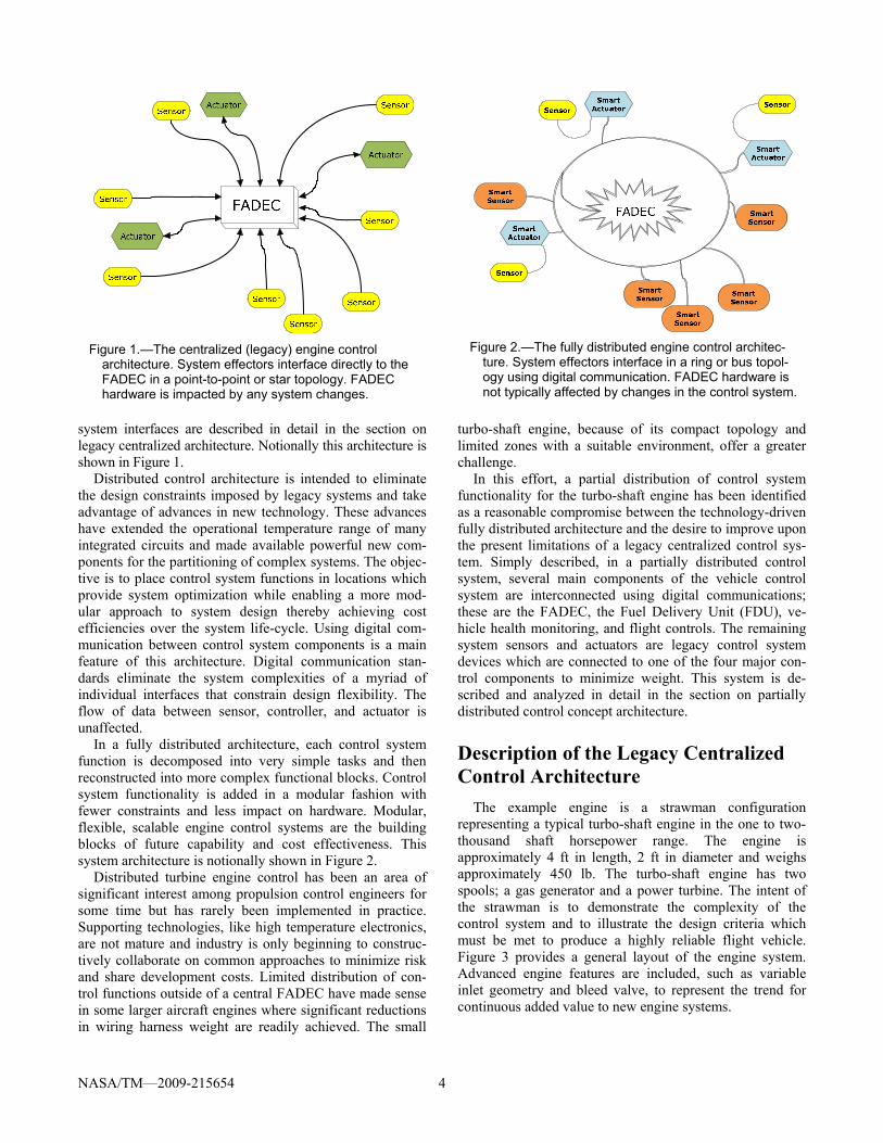
system interfaces are described in detail in the section on legacy centralized architecture. Notionally this architecture is shown in Figure 1.
Distributed control architecture is intended to eliminate the design constraints imposed by legacy systems and take advantage of advances in new technology. These advances have extended the operational temperature range of many integrated circuits and made available powerful new com-ponents for the partitioning of complex systems. The objec-tive is to place control system functions in locations which provide system optimization while enabling a more mod-ular approach to system design thereby achieving cost efficiencies over the system life-cycle. Using digital com-munication between control system components is a main feature of this architecture. Digital communication stan-dards eliminate the system complexities of a myriad of individual interfaces that constrain design flexibility. The flow of data between sensor, controller, and actuator is unaffected.
In a fully distributed architecture, each control system function is decomposed into very simple tasks and then reconstructed into more complex functional blocks. Control system functionality is added in a modular fashion with fewer constraints and less impact on hardware. Modular, flexible, scalable engine control systems are the building blocks of future capability and cost effectiveness. This system architecture is notionally shown in Figure 2.
Distributed turbine engine control has been an area of significant interest among propulsion control engineers for some time but has rarely been implemented in practice. Supporting technologies, like high temperature electronics, are not mature and industry is only beginning to construc-tively collaborate on common approaches to minimize risk and share development costs. Limited distribution of con-trol functions outside of a central FADEC have made sense in some larger aircraft engines where significant reductions in wiring harness weight are readily achieved. The small
turbo-shaft engine, because of its compact topology and limited zones with a suitable environment, offer a greater challenge.
In this effort, a partial distribution of control system functionality for the turbo-shaft engine has been identified as a reasonable compromise between the technology-driven fully distributed architecture and the desire to improve upon the present limitations of a legacy centralized control sys-tem. Simply described, in a partially distributed control system, several main components of the vehicle control system are interconnected using digital communications; these are the FADEC, the Fuel Delivery Unit (FDU), ve-hicle health monitoring, and flight controls. The remaining system sensors and actuators are legacy control system devices which are connected to one of the four major con-trol components to minimize weight. This system is de-scribed and analyzed in detail in the section on partially distributed control concept architecture.
Description of the Legacy Centralized Control Architecture
The example engine is a strawman configuration representing a typical turbo-shaft engine in the one to two-thousand shaft horsepower range. The engine is approximately 4 ft in length, 2 ft in diameter and weighs approximately 450 lb. The turbo-shaft engine has two spools; a gas generator and a power turbine. The intent of the strawman is to demonstrate the complexity of the control system and to illustrate the design criteria which must be met to produce a highly reliable flight vehicle. Figure 3 provides a general layout of the engine system. Advanced engine features are included, such as variable inlet geometry and bleed valve, to represent the trend for continuous added value to new engine systems.
Figure 2.—The fully distributed engine control architec-
ture. System effectors interface in a ring or bus topol-ogy using digital communication. FADEC hardware is not typically affected by changes in the control system.
Figure 1.—The centralized (legacy) engine control
architecture. System effectors interface directly to the FADEC in a point-to-point or star topology. FADEC hardware is impacted by any system changes.

NASA/TM—2009-215654 5
Figure 3.—The strawman turbo-shaft engine. The relative locations of control system components within the
compact mechanical topology are depicted.
The strawman control system represents a synthesis of engine controls currently in the existing worldwide helicop-ter fleet. The control architecture is a dual redundant FA-DEC to represent current state of the art in safety and reliability. In this configuration, two separate and indepen-dent channels reside in the FADEC. To provide redundant control, each engine sensor is typically constructed with dual elements to interface with each redundant FADEC channel. In contrast, engine actuators are typically con-structed with a single, common mechanism which is redun-dantly operated by the two FADEC channels. Both FADEC channels either have to agree on their position command (dual active control), or permit only one channel to operate the actuator at a time (active-standby control).
Engine Actuation
The gas generator has a compressor consisting of several axial stages, and one centrifugal stage. The axial stages of the compressor have variable geometry stators in the first several rows. These are scheduled from “closed” to “open”, as the engine power varies from minimum to maximum, and represents a continuous position demand. The bleed valve (BV) is located between the axial and centrifugal compressor stages. The BV can be either a “poppet” type, or a bleed band, requiring a single solenoid load to the FADEC, and represents an “on-off” demand. The engine also incorporates a supple-mentary “customer bleed” valve (CBV) which provides on-off control of the flow of compressor air to auxiliary equipment in the cabin. In operation under icing conditions, bleed air from the engine is required to “de-ice” inlet structures on the engine to prevent ice accumulation from causing damage to the en-gine components. The anti-ice bleed valve (AIBV) typically moves in response to the engine power demanded, and represents a continuous position demand.
The engine system incorporates an accessory gearbox which operates at a fraction of the main engine gas genera-tor rotor speed. The accessory gearbox is used to drive mechanical power loads in the vehicle system on the order of 1 to 5 percent of total engine power. It provides various speed output pads for the fuel boost pump, main fuel pump, the permanent magnet alternator, the lubrication scavenge pump, and other accessory power loads, as well as the input shaft for the starter.
Typically the fuel pumps and fuel metering function are integrated in an assembly known as the Fuel Delivery Unit (FDU). The fuel pump is generally a fixed displacement gear pump charged by an integral boost pump. The boost pump provides liquid fuel at a pressure above the vapor pressure of the fuel to the gear stage. The gear stage pressu-rizes and pumps the fuel to the metering unit. The fuel pump displacement is typically sized for start flow (low engine speed) on a fully deteriorated pump and flow is proportional to engine speed. As a result, there is typically excess flow that must be bypassed to the pump inlet at all other engine speeds, and at altitude operating conditions. This bypassed flow represents pump efficiency losses in the form of excess heat. The metering unit consists of the fuel metering valve, metering valve prime mover (step motor or torque motor actuated servo-valve), metering valve position feedback (RVDT or LVDT), the bypass meter head pres-sure regulator, high pressure relief valve, shut-off, over speed valve and solenoid.
Other features that are often incorporated in the FDU are temperature and pressure sensors, permanent magnet alter-nators that power the FADEC system, motive flow valves and actuators, as well as solenoids used for various purpos-es (engine and customer bleeds). All Electro-Mechanical Interface Devices (EMIDs) such as step or torque motors, PMAs, solenoids, and position feedback devices, as well as
EngineControl Unit
Insulation
Accessory GearboxQ / NpSensor
Ng SensorT1 / P1Sensor
P3Sensor
T45 Sensor
Axial
Compressor
BleedBand
Centrifugal
Compressor
OutputShaft
Fuel MeteringUnit
Combustor
FuelNozzles
CombustorC
oolin
g

NASA/TM—2009-215654 6
the any other sensors within the FDU, are typically dual channel devices. A summary of engine actuators are de-scribed in Table I.
Engine Sensors
Engine sensors are described in Table II. Critical control sensors Ng, and Np are redundant per channel meaning that each FADEC channel has access to two independent sen-sors for this speed data, while the remaining sensors are redundant per engine, meaning that each of the two engine control channels has access to one sensor, and a digital copy of the other channel’s sensor.
Airframe Inputs
Airframe inputs to the control system are often directly connected to controller. Some aircraft, however, integrate remote data collection into an airframe computer and transmit it to the FADEC over a reliable communication bus. If an airframe computer is employed, communication protocol is commonly ARINC 429 in commercial systems or Mil-Std-1553B in military. Control Area Network (CAN) communications may be used, in some cases, for
interchannel or inter-engine communications, or as a diag-nostic bus.
The FADEC also receives two sources of power, one from the airframe, and one from an engine gearbox or FDU mounted alternator, as previously mentioned. The redun-dant airframe supplied battery input is used for back-up as well as in engine start conditions. Data from the airframe is described in Table III.
Control Law Architecture
The FADEC control laws essentially work to maintain power turbine speed (Np) constant at the NpSet point. The control accomplishes this by scheduling a nominal Ng speed as a function of Collective Pitch, T1 and P1. The control trims this Ng demand to adjust Np isochronously to the NpSet input. The PLA position limits the maximum permissible Ng, and the control further limits the maximum T45. The control limits the rate of Ng acceleration/decele ration as a function of an Ng scheduled Wf/P3 limit. The FADEC controls Ng by modulating fuel flow (Wf), and actuating the bleed valve position and variable inlet geome-try position.
TABLE I.—TURBO-SHAFT ENGINE ACTUATORS Symbol Signal interface description Device technology Signal description Wires per channel
BV Bleed valve Solenoid Current sink 2 CBV Customer bleed valve Solenoid Current sink 2 AIBV Anti-ice bleed valve Servo Current sink 2 FMV Fuel metering valve Torque/stepper motor Current sink/
phase pattern 2
3 or 5
TABLE II.—TURBO-SHAFT ENGINE SENSORS Symbol Signal interface description Device technology Signal description Wires per channel
P1/T1 Inlet pressure Dual strain gauge Millivolt 4 Inlet temperature Dual RTD Millivolt 3
Ng (A) Gas generator speed Dual wound monopole Frequency 2 Ng (B) Gas generator speed Dual engine alternator
power Frequency 3
Np/Qs Power turbine speed Dual wound monopole Frequency 2 Power turbine speed Dual wound monopole Phase 2
P3 Compressor discharge pressure
Dual strain gage Millivolt 4
Wf Burned fuel flow Dual POT or dual VDT
Ratiometric voltage 3 5 or 6
T45 Power turbine inlet tempera-ture
Parallel thermocouples Millivolt 2
BVpos Bleed valve position Dual POT or Dual VDT
Ratiometric voltage 3 5 or 6
Vg Variable geometry position Dual POT or Dual VDT
Ratiometric voltage 3 5or 6
TABLE III.—AIRFRAME (HELICOPTER) INTERFACE
Symbol Signal interface description Device technology Signal description Wires per channel PLA Power lever angle (throttle) Dual POT or VDT Ratiometric voltage 3 to 6 Cp Collective pitch Dual POT or VDT Ratiometric voltage 3 to 6 NpSet/Trim Power turbine speed set point Dual POT or VDT Ratiometric voltage 3 Nr Rotor speed Multiply redundant
monopole Frequency 2
NASA/TM—2009-215654 7
As long as Ng and T45 remain within their limit, and the engine acceleration/deceleration ratio limits are preserved, the FADEC will work to maintain Np at 100 percent throughout the flight envelope. Per engine torque limiting as well as load sharing between multiple engines may also modify the operating set point of a given engine.
Supplemental logic identifies low power operation in a decoupled state to improve engine stability at low power, and improve transient response for the flight-idle to power-on case. This logic typically includes rotor speed decay anticipation in addition to the inherent collective anticipa-tion built into the core governor.
The criticality level for FADEC system components has been classified as Hazardous by governmental regulatory agencies. This means that control system failure can pre-vent further safe flight and landing. However, some func-tions of the FADEC can be considered catastrophic from an engine perspective only (loss of over-speed protection, and un-commanded engine acceleration). The resulting criteria must be considered by the system, software, and hardware respectively: • No single point failure can result in loss of over-speed
protection, and uncommanded acceleration. No single point failure should result in loss of thrust control.
• Software developed under DO-178B (Ref. 8) must follow requirements for “Level A,” the highest level of certification.
• Electronic hardware developed under DO-254 (Ref. 9) must follow requirements for “Level A”. Mechanical hardware must be developed under DO-160 (Ref. 10).
Unprotected over-speed (Probability of <1e-9)
In an unlikely over-speed event, the engine must be de-signed to contain the over-speed, mitigate the over-speed, or the control system must safely control the over-speed. In order to stress prevention over protection, the regulatory agencies have set a target loss of protection probability of 1e-4. This leaves a residual over-speed rate probability of 1e-5 for the engine design and control system prevention mechanisms. To minimize the rate of unprotected over-speed, the engine/control system must not contain common mode failures which simultaneously cause the over-speed and disable associated protection mechanisms.
Loss of thrust control (LOTC) The regulatory agencies have specified that the rate of
loss of thrust control should be at least as good as tradition-al hydro-mechanical systems. Therefore, all events which can contribute to this loss of thrust control should have a probability less than 1 per 100 k hr. Further, there should be no single point failure which causes LOTC.
Uncommanded thrust change The regulatory agencies have limited the rate of an
uncommanded thrust change to an equivalent hydro-mechanical system.
Data failures The regulatory agencies have limited the rate of impro-
per data between the engine control and the cockpit.
Environmental and Mechanical Considerations
The FADEC is typically mounted off-engine, or on the engine compressor case, taking advantage of the inlet air to sink internally produced heat. While the engine runs, ade-quate cooling is generally available to dissipate most heat loads, as well as the heat that soaks through from the engine compartment. However, immediately following engine shutdown the lack of cooling airflow reduces the available cooling. All engine components must remain below their temperature limits during the post shutdown soak back portion of operation.
The temperature environment on the engine varies from outside ambient (affected by flight conditions) to greater than 1000 °C (close to the combustor/turbine case). Even the more benign areas near the inlet have soak-back effects, where residual engine heat soaks out through the case and raises the temperature of anything within the engine cowling area. For this reason, most legacy centralized systems severely restrict the placement of electronics on-engine and locate most electronics off-engine, in a more benign environment.
Engine control components are typically located in the “air-borne uninhabited environment”, which means expo-sure to ambient pressure. Helicopters do not typically fly above 20,000 ft, so this limits pressure range between sea level, 14.7 psia, and about 7 psia. Some helicopters have demonstrated operation to 30,000 ft or about 4.5 psia, but this is beyond the typical operational envelope.
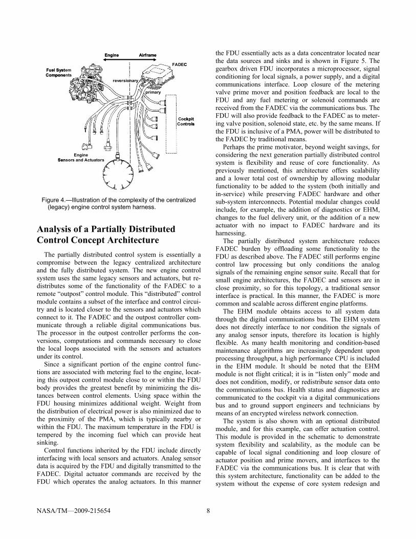
Numerous control system mechanical interfaces must be considered for their aerodynamic and structural affect and serviceability. The available volume on the engine for control system components is typically severely constrained by the engine components and the cowling. This complicates packaging which must accommodate accessibility of connectors and removal of components. The electrical harness assembly, shown in Figure 4, is a substantial mechanical component as all the individual wires for each sensor/actuator, protective shielding and over-braid to minimize lightning and EMI effects, and connector backshells are bulky. The effect of control component weight and mounting on the engine structure must be evaluated under normal and severe load conditions, including impact.
NASA/TM—2009-215654 8
Analysis of a Partially Distributed Control Concept Architecture
The partially distributed control system is essentially a compromise between the legacy centralized architecture and the fully distributed system. The new engine control system uses the same legacy sensors and actuators, but re-distributes some of the functionality of the FADEC to a remote “outpost” control module. This “distributed” control module contains a subset of the interface and control circui-try and is located closer to the sensors and actuators which connect to it. The FADEC and the outpost controller com-municate through a reliable digital communications bus. The processor in the outpost controller performs the con-versions, computations and commands necessary to close the local loops associated with the sensors and actuators under its control.
Since a significant portion of the engine control func-tions are associated with metering fuel to the engine, locat-ing this outpost control module close to or within the FDU body provides the greatest benefit by minimizing the dis-tances between control elements. Using space within the FDU housing minimizes additional weight. Weight from the distribution of electrical power is also minimized due to the proximity of the PMA, which is typically nearby or within the FDU. The maximum temperature in the FDU is tempered by the incoming fuel which can provide heat sinking.
Control functions inherited by the FDU include directly interfacing with local sensors and actuators. Analog sensor data is acquired by the FDU and digitally transmitted to the FADEC. Digital actuator commands are received by the FDU which operates the analog actuators. In this manner
the FDU essentially acts as a data concentrator located near the data sources and sinks and is shown in Figure 5. The gearbox driven FDU incorporates a microprocessor, signal conditioning for local signals, a power supply, and a digital communications interface. Loop closure of the metering valve prime mover and position feedback are local to the FDU and any fuel metering or solenoid commands are received from the FADEC via the communications bus. The FDU will also provide feedback to the FADEC as to meter-ing valve position, solenoid state, etc. by the same means. If the FDU is inclusive of a PMA, power will be distributed to the FADEC by traditional means.
Perhaps the prime motivator, beyond weight savings, for considering the next generation partially distributed control system is flexibility and reuse of core functionality. As previously mentioned, this architecture offers scalability and a lower total cost of ownership by allowing modular functionality to be added to the system (both initially and in-service) while preserving FADEC hardware and other sub-system interconnects. Potential modular changes could include, for example, the addition of diagnostics or EHM, changes to the fuel delivery unit, or the addition of a new actuator with no impact to FADEC hardware and its harnessing.
The partially distributed system architecture reduces FADEC burden by offloading some functionality to the FDU as described above. The FADEC still performs engine control law processing but only conditions the analog signals of the remaining engine sensor suite. Recall that for small engine architectures, the FADEC and sensors are in close proximity, so for this topology, a traditional sensor interface is practical. In this manner, the FADEC is more common and scalable across different engine platforms.
The EHM module obtains access to all system data through the digital communications bus. The EHM system does not directly interface to nor condition the signals of any analog sensor inputs, therefore its location is highly flexible. As many health monitoring and condition-based maintenance algorithms are increasingly dependent upon processing throughput, a high performance CPU is included in the EHM module. It should be noted that the EHM module is not flight critical; it is in “listen only” mode and does not condition, modify, or redistribute sensor data onto the communications bus. Health status and diagnostics are communicated to the cockpit via a digital communications bus and to ground support engineers and technicians by means of an encrypted wireless network connection.
The system is also shown with an optional distributed module, and for this example, can offer actuation control. This module is provided in the schematic to demonstrate system flexibility and scalability, as the module can be capable of local signal conditioning and loop closure of actuator position and prime movers, and interfaces to the FADEC via the communications bus. It is clear that with this system architecture, functionality can be added to the system without the expense of core system redesign and
Figure 4.—Illustration of the complexity of the centralized
(legacy) engine control system harness.
FADECFuel System Components
CockpitControls
Engine Airframe
Engine Sensors and Actuators
primary
reversionary
FADECFuel System Components
CockpitControls
Engine Airframe
Engine Sensors and Actuators
primary
reversionary

NASA/TM—2009-215654 9
Figure 5.—Partially distributed engine control architecture example—gearbox driven FDU. complete requalification. It should also be noted that it is critical to this architecture concept that spare data bus and power access is available on the FADEC, and optional distributed modules. Furthermore, the FDU and optional modules can also include spare analog I/O in addition to the digital data bus. This will enable system scalability and flexibility to accept the addition of local sensors, actuators, or distributed modules without hardware changes to the base system.
A variant of this distributed control configuration is shown in Figure 6. Here the mechanically powered fuel pumps are replaced with an electric drive system. The PMA remains mechanically coupled to the gearbox, but is exter-nal to the FDU and is substantially increased in capacity to power the pump motors. It is estimated that the PMA would be required to supply a maximum of 5 kW to drive the pump at 1250 pump horse power and 1250 psi for this size engine. In the previous configuration it only supplied about 100 W. A fuel control module, integral to the FDU, adjusts pump volumetric flow to eliminate the loss of efficiency developed in the mechanically driven system due to bypass flow. The entire FDU is packaged as an integral unit but is no longer required to be mechanically coupled to the gear-box. The increased pump efficiency is traded for the addi-tional weight in the PMA.
The distributed FDU and the EHM unit are also shown to be communicating digitally in a “daisy chain” fashion. This implies additional flexibility in distributed system configu-ration as the communication structure is in a bus or ring configuration. The implication is a further reduction of impact to the FADEC which would otherwise require
additional connectors for each distributed module con-nected in a star communication topology.
The FADEC architecture for the partially distributed control would likely appear as a dual system with each FADEC channel having a main and remote segment. Each segment would interface with the sensors and actuators which are local to it. Redundancy for the partially distri-buted architecture would not differ appreciably from the baseline. The standard I/O signals for the partially distri-buted system remain nearly identical to the conventional centralized architecture. Control law function and depen-dence on the numerous sensor signals that measure funda-mental engine parameters remain the same. The few exceptions to this are those sensors that are integral to optional distributed modules (e.g., actuator) and those that may vary with regard to gearbox driven or more-electric fuel metering technologies.
Safety, survivability, reliability, software criticality, and performance requirements of the hybrid architecture, at a minimum, must remain equal to the conventional centra-lized architecture. By virtue of the inclusion of state-of-the-art electronics and designs, it is reasonable to expect that the next generation distributed architecture will enable improved performance.
The communications bus selection will ultimately be dri-ven by fault tolerance and reliability, and by what is sup-ported by commercially available processors and electronics. Ideally, the chosen protocol will be widely accepted and adopted by industry. This communication bus may leverage existing airframe busses but will more likely utilize a dedicated engine control bus.
Engine
FDU
Comm
Power
Comm
ARINC Comm
Comm
Power
Optional Dist.Module
Comm
Power
Airframe Power
Wi-FiGSE
DUAL CHANNEL COMM BUS
MEM
DUAL CORECPU
SensorActuator
CPU
DUAL CHANNEL COMM BUS DUAL CHANNEL COMM BUS
MEM CPU
MEM CPU
DUAL CHANNELCOMM BUS
I/O & CommScalable FADEC
Engine HealthManagement
Module
CockpitFlight
Controls

NASA/TM—2009-215654 10
Figure 6.—Partially distributed engine control architecture example—electric fuel control.
Weight and Cost
A study comparing the legacy centralized control system and the partially distributed control system of Figure 5 was performed. Each system required an equivalent FADEC for control law processing. Cockpit and fuel system interfaces were specific to each system while the remaining engine sensor and actuator suite I/O remained connected to the FADEC in the traditional manner. The cockpit and FDU interfaces in the partially distributed system employed MIL-Std-1553 or ARINC bus in lieu of individual I/O. Power distribution and communications bus redundancy were taken into account for the partially distributed system. The notional traditional centralized architecture requires a pin count of 153 per channel, while the hybrid system requires a pin count of 74 per channel. The computed weight savings for the hybrid system is approximately 2.6 lb. The results are tabulated in Table IV. While the overall FADEC, wire harness, and connector weights for the partially distributed were reduced, the fuel pump and control unit increased in weight. This is due to the addition and accommodation of electronics required for signal conditioning of sensors and position feedback, local loop closure of the metered fuel command by the FADEC, and the data bus interface. It should be noted that this study was conducted considering a gearbox mounted and driven FDU and that a further weight decrease can be expected with an electric motor driven fuel metering pump.
In addition to the weight savings, estimates indicate an as yet unquantified cost reduction by replacing the traditional gearbox driven hydromechanical unit with an electric fuel metering unit. A reduction in component count, and thereby cost, is achieved by means of eliminating costly precision
valves and electro-mechanical interface devices such as step motors and metering valve position feedback. A direct metering system by means of an electric motor driven positive displacement pump also offers unparalleled fuel metering accuracy when closing the loop on pressure or flow feedback and by incorporating temperature and pump degradation effects into the control laws.
TABLE IV.—WEIGHT COMPARISON FOR CENTRALIZED AND PARTIALL DISTRIBUTED
SYSTEM ARCHITECTURES Centralized architecture weight
FADEC 7.60 lb FDU 13.88 lb Harnesses 6.03 lb Total 27.51 lb Partially distributed architecture weight FADEC 6.40 lb FDU 15.62 lb Harnesses 2.92 lb Total 24.94 lb Difference 2.57 lb
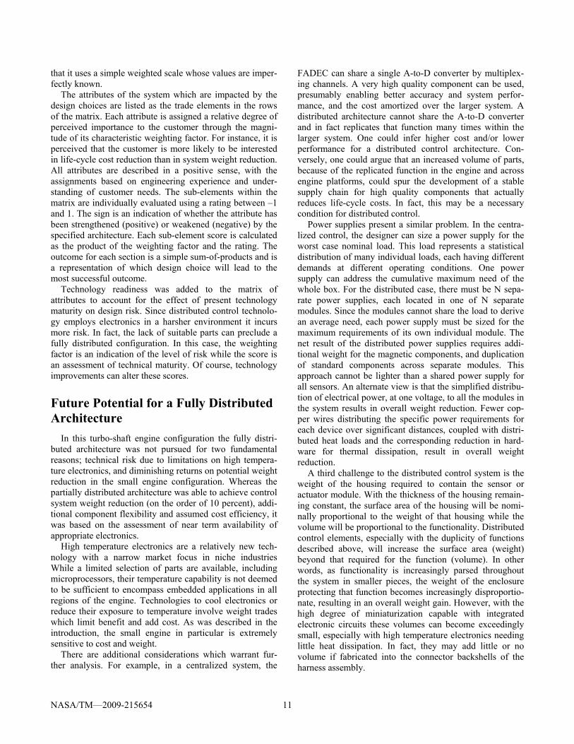
Control Architecture Comparison Matrix—(Pugh Matrix)
The following spreadsheet, shown in Table IV, describes the result of an assessment of control system architecture with respect to the system characteristics of performance, weight, reliability, safety, life cycle cost, and technology readiness. The technique is known as a Pugh Matrix and is used by engineers as a means to make a relative comparison of design choices and their impact on overall customer value. The technique is a qualitative tool based on the fact
CockpitFlight
Controls
EngineScalable FADEC
Engine HealthManagement
Module
Comm Power
Comm
ARINC Comm
I/O &Comm
PMAPower
Fuel ControlModule
Comm Power
Airframe Power
ElectricFuel
Control
Wi-Fi
GSE
Metered Fuel
270 VDC Power
DUAL CHANNEL COMM BUS
MEM
Optional Dist.Module
Comm Power
DUAL CORECPU
SensorActuator
CPU
DUAL CHANNEL COMM BUS
DUAL CHANNEL COMM BUS
MEM CPU
DUAL CHANNEL COMM BUS
MEM CPU
FDU
NASA/TM—2009-215654 11
that it uses a simple weighted scale whose values are imper-fectly known.
The attributes of the system which are impacted by the design choices are listed as the trade elements in the rows of the matrix. Each attribute is assigned a relative degree of perceived importance to the customer through the magni-tude of its characteristic weighting factor. For instance, it is perceived that the customer is more likely to be interested in life-cycle cost reduction than in system weight reduction. All attributes are described in a positive sense, with the assignments based on engineering experience and under-standing of customer needs. The sub-elements within the matrix are individually evaluated using a rating between –1 and 1. The sign is an indication of whether the attribute has been strengthened (positive) or weakened (negative) by the specified architecture. Each sub-element score is calculated as the product of the weighting factor and the rating. The outcome for each section is a simple sum-of-products and is a representation of which design choice will lead to the most successful outcome.
Technology readiness was added to the matrix of attributes to account for the effect of present technology maturity on design risk. Since distributed control technolo-gy employs electronics in a harsher environment it incurs more risk. In fact, the lack of suitable parts can preclude a fully distributed configuration. In this case, the weighting factor is an indication of the level of risk while the score is an assessment of technical maturity. Of course, technology improvements can alter these scores.
Future Potential for a Fully Distributed Architecture
In this turbo-shaft engine configuration the fully distri-buted architecture was not pursued for two fundamental reasons; technical risk due to limitations on high tempera-ture electronics, and diminishing returns on potential weight reduction in the small engine configuration. Whereas the partially distributed architecture was able to achieve control system weight reduction (on the order of 10 percent), addi-tional component flexibility and assumed cost efficiency, it was based on the assessment of near term availability of appropriate electronics.
High temperature electronics are a relatively new tech-nology with a narrow market focus in niche industries While a limited selection of parts are available, including microprocessors, their temperature capability is not deemed to be sufficient to encompass embedded applications in all regions of the engine. Technologies to cool electronics or reduce their exposure to temperature involve weight trades which limit benefit and add cost. As was described in the introduction, the small engine in particular is extremely sensitive to cost and weight.
There are additional considerations which warrant fur-ther analysis. For example, in a centralized system, the
FADEC can share a single A-to-D converter by multiplex-ing channels. A very high quality component can be used, presumably enabling better accuracy and system perfor-mance, and the cost amortized over the larger system. A distributed architecture cannot share the A-to-D converter and in fact replicates that function many times within the larger system. One could infer higher cost and/or lower performance for a distributed control architecture. Con-versely, one could argue that an increased volume of parts, because of the replicated function in the engine and across engine platforms, could spur the development of a stable supply chain for high quality components that actually reduces life-cycle costs. In fact, this may be a necessary condition for distributed control.
Power supplies present a similar problem. In the centra-lized control, the designer can size a power supply for the worst case nominal load. This load represents a statistical distribution of many individual loads, each having different demands at different operating conditions. One power supply can address the cumulative maximum need of the whole box. For the distributed case, there must be N sepa-rate power supplies, each located in one of N separate modules. Since the modules cannot share the load to derive an average need, each power supply must be sized for the maximum requirements of its own individual module. The net result of the distributed power supplies requires addi-tional weight for the magnetic components, and duplication of standard components across separate modules. This approach cannot be lighter than a shared power supply for all sensors. An alternate view is that the simplified distribu-tion of electrical power, at one voltage, to all the modules in the system results in overall weight reduction. Fewer cop-per wires distributing the specific power requirements for each device over significant distances, coupled with distri-buted heat loads and the corresponding reduction in hard-ware for thermal dissipation, result in overall weight reduction.
A third challenge to the distributed control system is the weight of the housing required to contain the sensor or actuator module. With the thickness of the housing remain-ing constant, the surface area of the housing will be nomi-nally proportional to the weight of that housing while the volume will be proportional to the functionality. Distributed control elements, especially with the duplicity of functions described above, will increase the surface area (weight) beyond that required for the function (volume). In other words, as functionality is increasingly parsed throughout the system in smaller pieces, the weight of the enclosure protecting that function becomes increasingly disproportio-nate, resulting in an overall weight gain. However, with the high degree of miniaturization capable with integrated electronic circuits these volumes can become exceedingly small, especially with high temperature electronics needing little heat dissipation. In fact, they may add little or no volume if fabricated into the connector backshells of the harness assembly.

NASA/TM—2009-215654 12
While the software criticality level of both architectures remains the same, the implicit physical partitioning built into distributed system architecture minimizes the ability for software in one component to induce faults in another com-ponent, reducing software complexity. Maintaining software integrity at the defined interface should provide sufficient evidence to the certification authority to accept replacement at a component level; however, the current interpretation of the certification rules may need to be adjusted. Once the benefits of distributed software have been demonstrated, and accepted by the certification authorities, software certifica-tion costs should decrease.
Perhaps the greatest benefit of the fully distributed en-gine control system is the potential for increased cost shar-ing and visibility into the engine system. Distributed control brings the capability to embed tremendous functionality into system components. While this added technology may increase acquisition cost, the likelihood of increased cus-tomer value through lower life cycle costs is quite high. In fact every phase of the life cycle could experience reduced cost through modularity which decreases nonrecurring engineering cost, commonality across various engine sys-tems which increases volume and economy of scale, and system availability through increased fault isolation which reduces operating costs.
The ability to achieve this vision of fully distributed engine control systems seems to be contingent on the user community to cooperatively invest in technology develop-ment in order to share costs and increase the potential for stable supplier markets in critical high temperature compo-nents. This cooperation is being pursued through the Distri-buted Engine Control Working Group (DEWG), a consortium of government and industry stakeholders vested in turbine propulsion systems. The interaction of this group provides a forum for the discussion of precompetetive technologies which can be co-developed and shared. One such area is the identification and requirement definition of integrated electronic functions which are the building blocks of modular systems. Contingent upon the electronics capability is the potential for common digital communica-tion protocol to connect modular components into flexible and scalable systems.
Conclusion Turbo-shaft engine systems are an important class of
engines which are often used for helicopter propulsion. While similar to other turbine engines used in aircraft, they are characterized by a very compact topology and an un-usually high degree of dynamic coupling with the airframe which complicates engine control. Engine system weight and cost are major factors in turbo-shaft engine design.
Two control system architectures, centralized and distributed, were presented and their major attributes were described. The legacy, centralized architecture was
provided as a detailed description of a strawman design based on the turbo-shaft engine in the 1000 to 2000 hp range. Turbo-shaft engine control systems currently in use are of this architecture, where engine control electronics are predominantly housed in a common location within an enclosure protected from heat and other environmental conditions. All system control elements interface directly to this electronics package through a complex wire harness assembly. Any changes to this control system architecture require significant redesign throughout the system with a great investment in time and cost.
The distributed engine control architecture is characte-rized by a de-centralized design where electronics are embedded very near to each control element function. The integral electronics offload the burden from a central con-troller and communicate system data through a digital communication network. The architecture offers a high degree of system modularity and flexibility in the design of scalable engine control systems. New electronics technolo-gies, such as high temperature electronics, are required for implementation which increases design risk.
A compromise, the partially distributed control architec-ture was deemed to offer the greatest balance between technology risk and improved system benefits. The results of a comprehensive analysis of a strawman, partially distri-buted, turbo-shaft engine control system were presented. Significant details of the system were described, including a Fuel Delivery Unit (FDU) which offloaded the Full Author-ity Digital Engine Controller (FADEC) burden with integral processing capability. Legacy fuel system sensors and actuators interface directly to this unit instead of the FA-DEC. System modularity is enhanced by digital communi-cations between the FADEC and FDU and between the FADEC and cockpit flight controls. This modularity ap-pears to save control system weight, on the order of 10 percent. In addition, the potential for cost reduction exists by isolating the effect of changes within the given control system and offering the reuse of modular elements in other engine control systems.
In the turbo-shaft engine system, the partially distributed control system configuration is deemed to be a viable alternative for near-term system development because of the availability of a viable, although limited, pool of high temperature electronic components which provide the capability to embed sufficient processing capability on-engine. Fully distributed engine control was not as tho-roughly analyzed due to perceived limitations in these electronic components. Additional electronics capability at higher temperatures, and with increased levels of integra-tion and miniaturization of control functions, are seen as near-term deficiencies in need of further development. Some of the technical questions and future needs of a fully distributed engine control system and the potential system benefits were explored.
NA
SA/T
M—
2009
-215
654
13
TAB
LE V
.—TH
E PU
GH
MA
TRIX
. [A
n as
sess
men
t of t
he m
erits
of c
ontro
l arc
hite
ctur
e w
ith re
spec
t to
cust
omer
val
ue.]
ratin
gsc
ore
ratin
gsc
ore
ratin
gsc
ore
Perf
orm
ance
(2)
tota
l val
ue o
f per
form
ance
enh
ance
men
t tec
hnol
ogy
Sup
ports
Adv
ance
d C
ontro
l Alg
orith
ms
0.70
00
0.80
0.56
0.50
0.35
valu
e of
eas
ily u
pdat
ed c
ontro
l alg
orith
ms
Sup
ports
Inco
rpor
atio
n of
Lat
est T
echn
olog
ies
0.30
00
0.70
0.21
0.50
0.15
valu
e of
inse
rting
new
con
trol t
echn
olog
y1.
000
0.77
0.50
Perf
orm
ance
Sco
re
Syst
em W
eigh
t (2)
tota
l val
ue o
f wei
ght r
educ
tion
FAD
EC
Wei
ght
0.40
00
0.50
0.20
0.25
0.10
valu
e of
FA
DE
C w
eigh
t red
uctio
nFu
el S
yste
m C
ompo
nent
Wei
ght
0.80
00
-0.2
0-0
.16
-0.1
0-0
.08
valu
e of
FD
U w
eigh
t red
uctio
nH
arne
ss W
eigh
t0.
400
00.
500.
200.
250.
10va
lue
of s
yste
m in
terc
onne
ct w
eigh
t red
uctio
nS
enso
r/ A
ctua
tor W
eigh
t0.
400
0-0
.20
-0.0
80.
000.
00va
lue
of s
enso
r/act
uato
r wei
ght r
educ
tion
2.00
00.
160.
12Sy
stem
Wei
ght S
core
Rel
iabi
lity
(2)
tota
l val
ue o
f rel
iabi
lity
impr
ovem
ents
FAD
EC
Rel
iabi
lity
0.10
00
0.50
0.05
0.25
0.03
valu
e of
impr
oved
FAD
EC
relia
bilit
yFu
el S
yste
m R
elia
bilit
y0.
200
0-0
.20
-0.0
4-0
.10
-0.0
2va
lue
of im
prov
ed F
DU
relia
bilit
y
Har
ness
Rel
iabi
lity
0.50
00
1.00
0.50
0.50
0.25
valu
e of
sys
tem
inte
rcon
nect
ion
relia
bilit
y im
prov
emen
tS
enso
r/Act
uato
r Rel
iabi
lity
0.20
00
-0.1
0-0
.02
0.00
0.00
valu
e of
sen
sor/a
ctua
tor r
elia
bilit
y im
prov
emen
t1.
000
0.49
0.26
Rel
iabi
lity
Scor
e
Syst
em S
afet
y (2
)to
tal v
alue
of s
afet
y im
prov
emen
tsS
elf-D
iagn
ostic
Cap
abilit
y0.
330
00.
300.
100.
100.
03va
lue
of im
prov
ed fa
ult d
iagn
ostic
sFa
ult T
oler
ance
0.67
00
0.30
0.20
0.10
0.07
valu
e of
impr
oved
faul
t rec
over
y/to
lera
nce
1.00
00.
300.
10Sy
stem
Saf
ety
Scor
e
Life
cycl
e C
ost (
2)to
tal v
alue
of c
ost r
educ
tions
Sys
tem
Dev
elop
men
t Cos
t0.
800
00.
500.
400.
100.
08va
lue
of re
duci
ng d
evel
opm
ent c
ost
Sys
tem
Pro
duct
ion/
acqu
isiti
on C
ost
1.60
00
-0.2
0-0
.32
-0.1
0-0
.16
valu
e of
redu
cing
the
syst
em a
cqui
sitio
n co
stS
yste
m S
usta
inm
ent C
ost
1.60
00
0.00
valu
e of
redu
cing
sys
tem
sus
tain
men
t cos
ts
Mai
nten
ance
Cos
t1.
120
00.
00va
lue
of re
duci
ng m
aint
enan
ce c
osts
in e
xist
ing
conf
igur
atio
nFa
ult D
iagn
osis
0.90
00
1.00
0.90
0.10
0.09
valu
e of
redu
cing
tim
e to
find
faul
tsFa
ult C
orre
ctio
n0.
220
01.
000.
220.
100.
02va
lue
of re
duci
ng ti
me/
cost
to c
orre
ct fa
ults
Upg
rade
Cos
t0.
480
01.
000.
480.
300.
14va
lue
of re
duci
ng th
e co
st o
f upg
rade
s4.
000
1.68
0.18
Life
cycl
e C
ost S
core
Tech
nolo
gy R
eadi
ness
(3)
tota
l sen
sitiv
ity to
tech
nolo
gy im
pact
on
sche
dule
and
co
st ri
skH
igh
Tem
pera
ture
Ele
ctro
nics
Tec
hnol
ogy
4.00
00
-0.9
0-3
.60
-0.1
0-0
.40
avai
labi
lity
of h
igh
tem
p el
ectro
nics
Con
trol C
omm
unic
atio
ns T
echn
olog
y1.
000
0-0
.80
-0.8
0-0
.10
-0.1
0av
aila
bilit
y of
real
-tim
e co
mm
unic
atio
nsS
oftw
are
Tech
nolo
gy2.
000
0-0
.80
-1.6
00.
000.
00av
aila
bilit
y of
SW
par
titio
ning
& d
evel
opm
ent t
ools
Sys
tem
Inte
grat
ion
Tech
nolo
gy1.
000
0-0
.40
-0.4
00.
000.
00av
aila
bilit
y of
man
ufac
turin
g pr
oces
ses
Flig
ht C
ertif
icat
ion
2.00
00
-0.8
0-1
.60
-0.1
0-0
.20
regu
lato
ry a
genc
y bu
y-in
10.0
00
-4.4
0-0
.30
Tech
nolo
gy R
eadi
ness
Sco
re
Com
posi
te R
esul
t19
.00
0.00
-1.0
00.
85C
ompo
site
Sco
re0.
00%
-5.2
6%4.
48%
Nor
mal
ized
Com
posi
te S
core
Not
es:
Cen
tral
ized
(1)
Fully
Dis
trib
uted
Part
ially
Dis
trib
uted
2. A
ssum
es s
yste
m is
suc
cess
fully
impl
emen
ted
with
read
ily a
vaila
ble
tech
nolo
gy; T
echn
olog
y re
adin
ess
is a
sses
sed
inde
pend
ently
.3.
Ass
umes
tech
nolo
gy re
adin
ess
is a
sig
nific
ant b
arrie
r to
prod
uctio
n
1. L
egac
y C
entra
lized
arc
hite
ctur
e is
bas
elin
e, c
urre
nt s
tate
of t
he a
rt.
Con
trol
Arc
hite
ctur
eC
hara
cter
istic
W
eigh
ting
Trad
e El
emen
tD
escr
iptio
n
NASA/TM—2009-215654 14
References 1. Porter, L., “NASA’s New Aeronautics Research Pro-
gram,” presentation to the 45th AIAA Aerospace Sciences Meeting & Exhibit, January 2007, Reno, NV.
2. The Versatile Affordable Advanced Turbine Engines (VAATE) Initiative, AIAA Position Paper, January 2006.
3. Lewis, T.J., “Distributed Architectures for Advanced Engine Control Systems,” AGARD/PEP 86th Sympo-sium on Advanced Aero-Engine Concepts and Con-trols, Seattle, 1995.
4. Culley, D.E., Thomas, R., Saus, J., “Concepts for Distributed Engine Control,” 43rd AIAA/ASME/ SAE/ASEE Joint Propulsion Conference and Exhibit, Cincinnati, OH, July 8–11, 2007, AIAA–2007–5709.
5. Behbahani, A.R., Culley, D., Smith, B.J., et al., “Sta-tus, Vision, and Challenges of an Intelligent Distri-buted Engine Control Architecture,” 2007–01–3859, SAE AeroTech Congress & Exhibition, September 2007, Los Angeles, CA.
6. Painter, M.K., Erraguntla, M., Hogg, G.L. Jr., Beach-kofski, B., “Using Simulation, Data Mining, and Knowledge Discovery Techniques for Optimized Air-craft Engine Fleet Management,” Proceeding of the 2006 Winter Simulation Conference, IEEE 2006.
7. Jaw, L.C., Garg, S., “Propulsion Control Technology Development in the United States A Historical Pers-pective,” NASA/TM—2005-213978.
8. DO-254, Design Assurance Guidance for Airborne Electronic Hardware, www.rtca.org.
9. DO-178B, Software Considerations in Airborne Sys-tems and Equipment Certification, www.rtca.org.
10. DO-160A-F, Environmental Conditions and Test Procedures for Airborne Equipment, www.rtca.org.
REPORT DOCUMENTATION PAGE Form Approved OMB No. 0704-0188
The public reporting burden for this collection of information is estimated to average 1 hour per response, including the time for reviewing instructions, searching existing data sources, gathering and maintaining the data needed, and completing and reviewing the collection of information. Send comments regarding this burden estimate or any other aspect of this collection of information, including suggestions for reducing this burden, to Department of Defense, Washington Headquarters Services, Directorate for Information Operations and Reports (0704-0188), 1215 Jefferson Davis Highway, Suite 1204, Arlington, VA 22202-4302. Respondents should be aware that notwithstanding any other provision of law, no person shall be subject to any penalty for failing to comply with a collection of information if it does not display a currently valid OMB control number. PLEASE DO NOT RETURN YOUR FORM TO THE ABOVE ADDRESS. 1. REPORT DATE (DD-MM-YYYY) 01-09-2009
2. REPORT TYPE Technical Memorandum
3. DATES COVERED (From - To)
4. TITLE AND SUBTITLE The Case for Distributed Engine Control in Turbo-Shaft Engine Systems
5a. CONTRACT NUMBER
5b. GRANT NUMBER
5c. PROGRAM ELEMENT NUMBER
6. AUTHOR(S) Culley, Dennis, E.; Paluszewski, Paul, J.; Storey, William; Smith, Bert, J.
5d. PROJECT NUMBER
5e. TASK NUMBER
5f. WORK UNIT NUMBER WBS 561581.02.08.03.17.03
7. PERFORMING ORGANIZATION NAME(S) AND ADDRESS(ES) National Aeronautics and Space Administration John H. Glenn Research Center at Lewis Field Cleveland, Ohio 44135-3191
8. PERFORMING ORGANIZATION REPORT NUMBER E-16966
9. SPONSORING/MONITORING AGENCY NAME(S) AND ADDRESS(ES) National Aeronautics and Space Administration Washington, DC 20546-0001
10. SPONSORING/MONITOR'S ACRONYM(S) NASA
11. SPONSORING/MONITORING REPORT NUMBER NASA/TM-2009-215654
12. DISTRIBUTION/AVAILABILITY STATEMENT Unclassified-Unlimited Subject Category: 07 Available electronically at http://gltrs.grc.nasa.gov This publication is available from the NASA Center for AeroSpace Information, 443-757-5802
13. SUPPLEMENTARY NOTES
14. ABSTRACT The turbo-shaft engine is an important propulsion system used to power vehicles on land, sea, and in the air. As the power plant for many high performance helicopters, the characteristics of the engine and control are critical to proper vehicle operation as well as being the main determinant to overall vehicle performance. When applied to vertical flight, important distinctions exist in the turbo-shaft engine control system due to the high degree of dynamic coupling between the engine and airframe and the affect on vehicle handling characteristics. In this study, the impact of engine control system architecture is explored relative to engine performance, weight, reliability, safety, and overall cost. Comparison of the impact of architecture on these metrics is investigated as the control system is modified from a legacy centralized structure to a more distributed configuration. A composite strawman system which is typical of turbo-shaft engines in the 1000 to 2000 hp class is described and used for comparison. The overall benefits of these changes to control system architecture are assessed. The availability of supporting technologies to achieve this evolution is also discussed.15. SUBJECT TERMS Control; Turbine; Propulsion; Distributed control
16. SECURITY CLASSIFICATION OF: 17. LIMITATION OF ABSTRACT UU
18. NUMBER OF PAGES
20
19a. NAME OF RESPONSIBLE PERSON STI Help Desk (email:[email protected])
a. REPORT U
b. ABSTRACT U
c. THIS PAGE U
19b. TELEPHONE NUMBER (include area code) 44.3-757-5802
Standard Form 298 (Rev. 8-98)Prescribed by ANSI Std. Z39-18

