group 11c engine mechanical - lil … turbo engine overhaul manual... · sealants engine...
TRANSCRIPT

11C-1
GROUP 11C
ENGINE MECHANICAL <4G63-Turbo>
CONTENTS
GENERAL INFORMATION . . . . . . . . 11C-2
SERVICE SPECIFICATIONS. . . . . . . 11C-2
SEALANTS . . . . . . . . . . . . . . . . . . . . 11C-3
SPECIAL TOOLS. . . . . . . . . . . . . . . . 11C-4
ON-VEHICLE SERVICE. . . . . . . . . . . 11C-8DRIVE BELT TENSION CHECK. . . . . . . . . 11C-8AUTO-TENSIONER CHECK . . . . . . . . . . . 11C-8IGNITION TIMING CHECK. . . . . . . . . . . . . 11C-10IDLE SPEED CHECK . . . . . . . . . . . . . . . . . 11C-11IDLE MIXTURE CHECK . . . . . . . . . . . . . . . 11C-12COMPRESSION PRESSURE CHECK. . . . 11C-12MANIFOLD VACUUM CHECK . . . . . . . . . . 11C-13LASH ADJUSTER CHECK . . . . . . . . . . . . . 11C-14
CRANKSHAFT PULLEY . . . . . . . . . . 11C-16REMOVAL AND INSTALLATION . . . . . . . . 11C-16
CAMSHAFT AND VALVE STEM SEAL. . . . . . . . . . . . . . . . . . . . . . . . . . 11C-17
REMOVAL AND INSTALLATION . . . . . . . . 11C-17
OIL PAN . . . . . . . . . . . . . . . . . . . . . . . 11C-25REMOVAL AND INSTALLATION . . . . . . . . 11C-25INSPECTION. . . . . . . . . . . . . . . . . . . . . . . . 11C-27
CRANKSHAFT OIL SEAL . . . . . . . . . 11C-28REMOVAL AND INSTALLATION . . . . . . . . 11C-28
CYLINDER HEAD GASKET . . . . . . . . 11C-30REMOVAL AND INSTALLATION . . . . . . . . 11C-30
TIMING BELT . . . . . . . . . . . . . . . . . . . 11C-34REMOVAL AND INSTALLATION . . . . . . . . 11C-34INSPECTION. . . . . . . . . . . . . . . . . . . . . . . . 11C-42
ENGINE ASSEMBLY . . . . . . . . . . . . . 11C-43REMOVAL AND INSTALLATION . . . . . . . . 11C-43
GENERAL INFORMATIONENGINE MECHANICAL <4G63-Turbo>11C-2
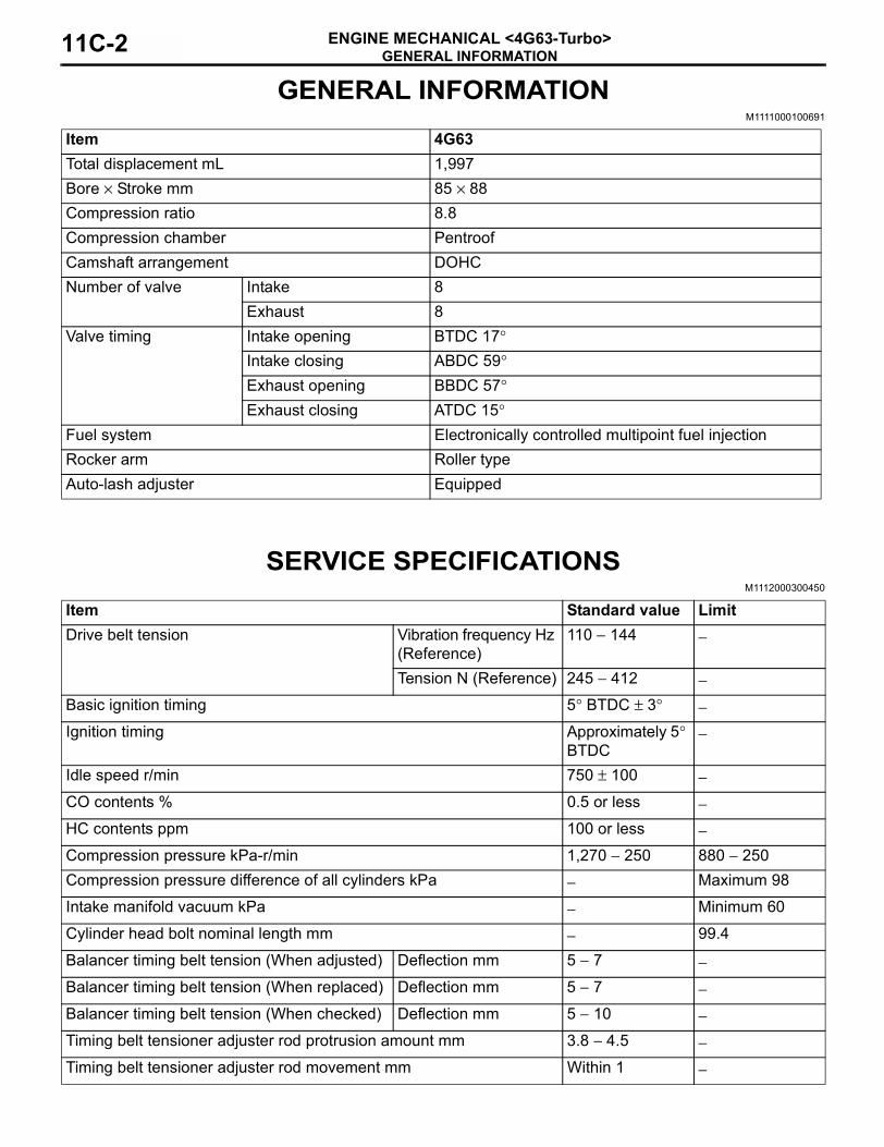
GENERAL INFORMATIONM1111000100691
SERVICE SPECIFICATIONSM1112000300450
Item 4G63Total displacement mL 1,997Bore × Stroke mm 85 × 88Compression ratio 8.8Compression chamber PentroofCamshaft arrangement DOHCNumber of valve Intake 8
Exhaust 8Valve timing Intake opening BTDC 17°
Intake closing ABDC 59°Exhaust opening BBDC 57°Exhaust closing ATDC 15°
Fuel system Electronically controlled multipoint fuel injectionRocker arm Roller typeAuto-lash adjuster Equipped
Item Standard value LimitDrive belt tension Vibration frequency Hz
(Reference)110 − 144 −
Tension N (Reference) 245 − 412 −Basic ignition timing 5° BTDC ± 3° −Ignition timing Approximately 5°
BTDC−
Idle speed r/min 750 ± 100 −CO contents % 0.5 or less −HC contents ppm 100 or less −Compression pressure kPa-r/min 1,270 − 250 880 − 250Compression pressure difference of all cylinders kPa − Maximum 98
Intake manifold vacuum kPa − Minimum 60
Cylinder head bolt nominal length mm − 99.4
Balancer timing belt tension (When adjusted) Deflection mm 5 − 7 −Balancer timing belt tension (When replaced) Deflection mm 5 − 7 −Balancer timing belt tension (When checked) Deflection mm 5 − 10 −Timing belt tensioner adjuster rod protrusion amount mm 3.8 − 4.5 −Timing belt tensioner adjuster rod movement mm Within 1 −

SEALANTSENGINE MECHANICAL <4G63-Turbo> 11C-3
SEALANTSM1112000500410
Item Specified Sealant RemarkCylinder head MITSUBISHI GENUINE PART MD970389 or
equivalentSemi-drying sealantCamshaft position sensor support
Rocker coverCamshaft end seal 3M ATD Part No. 8660 or equivalentRocker cover gasket MITSUBISHI GENUINE PART MD970389 or
equivalentEngine upper oil panEngine lower oil pan

SPECIAL TOOLSENGINE MECHANICAL <4G63-Turbo>11C-4
SPECIAL TOOLSM1112000600570
Tool Number Name UseMB991502 MUT-II sub assembly • Drive belt tension check
• Checking the ignition timing• Checking the idle speed
MB991955A: MB991824B: MB991827C: MB991910D: MB991911E: MB991825F: MB991826
MUT-III sub assemblyA: Vehicle communication
interface (V.C.I.)B: MUT-III USB cableC: MUT-III main harness A
(Vehicles with CAN communication system)
D: MUT-III main harness B (Vehicles without CAN communication system)
E: MUT-III measurement adapter
F: MUT-III trigger harness
Drive belt tension checkCAUTION
If you connect MUT-III main harness A to a vehicle without CAN communication system to use the MUT-III, a pulse signal may interfere with the simulated vehicle speed lines, thus causing the MUT-III inoperative. Therefore, use the MUT-III main harness B (MB991911) instead.
MB991668 Belt tension meter set Drive belt tension check (used together with MUT-II or MUT-III)
B991502
MB991910
MB991826
MB991955
MB991911
MB991824
MB991827
MB991825
A
B
C
D
E
F
DO NOT USED
B991668

SPECIAL TOOLSENGINE MECHANICAL <4G63-Turbo> 11C-5
MD998772 Valve spring compressor Compressing valve spring
MD998737 Valve stem seal installer Valve stem seal installation
MD998713 Camshaft oil seal installer Camshaft oil seal installation
MD998781 Flywheel stopper Supporting the flywheel
MB990938 Installer bar Crankshaft rear oil seal installation
MD998776 Crankshaft rear oil seal installer
MD998285 Crankshaft front oil seal guide
Crankshaft front oil seal installation
MD998375 Crankshaft front oil seal installer
Tool Number Name Use
MD998772
D998713
D998781
D998776
D998285

SPECIAL TOOLSENGINE MECHANICAL <4G63-Turbo>11C-6
MB991654 Cylinder head bolt wrench (12)
Removal and installation of cylinder head bolt
MD998738 Adjusting bolt Supporting the timing belt tensioner arm and timing belt tensioner adjuster
MB991367 Special spanner Holding the crankshaft camshaft drive sprocket
MB991385 Pin
MD998767 Tensioner wrench Valve timing belt tension adjustment
Tool Number Name Use
B991654
D998738
B991367
B991385
D998767

SPECIAL TOOLSENGINE MECHANICAL <4G63-Turbo> 11C-7
MB991454 Engine hanger balancer When the engine hanger is used: Supporting the engine assembly during removal and installation of the transmission assemblyNOTE: Special tool MB991454 is a part of engine hanger attachment set MB991453.
MB991527 Hanger
MB991895 Engine hanger
MB991928A: MB991929B: MB991930C: MB991931D: MB991932E: MB991933F: MB991934
Engine hangerA: Joint (50) × 2B: Joint (90) × 2C: Joint (140) × 2D: Foot (standard) × 4E: Foot (short) × 2F: Chain and hook assembly
Tool Number Name Use
B991454
B991527
Z203830
B991928
A
BC
D
E
F
Slide bracket (HI)

ON-VEHICLE SERVICEENGINE MECHANICAL <4G63-Turbo>11C-8
ON-VEHICLE SERVICEDRIVE BELT TENSION CHECK
M1111003100805
CAUTIONCheck the drive belt tension after turning the crankshaft clockwise one turn or more.
1. Make sure that the indicator mark is within the area marked with A in the illustration.
2. If the mark is out of the area, replace the drive belt. (Refer to P.11C-16).NOTE: The drive belt tension check is not necessary as auto-tensioner is adopted.
AUTO-TENSIONER CHECKM1111003000240
OPERATION CHECK1. Turn OFF the engine from the idle state then
check to see that the drive belt is not protruding from the pulley width of the auto-tensioner.
2. Remove the drive belt.(Refer to P.11C-16).
3. Securely insert the spindle handle or ratchet handle with a 12.7 mm insertion angle into the jig hole of the auto tensioner. Turn the auto-tensioner to the left and right to check and see that there is no threading.
4. If there are any problems in the procedure 1 or 3, replace the auto-tensioner.(Refer to P.11C-34).
5. Install the drive belt.(Refer to P.11C-16).
FUNCTION CHECKYou can verify if the auto-tensioner is defective or not by checking the drive belt tension.When using MUT-II1. Check the drive belt tension. (Refer to P.11A-8).2. Measure the drive belt tension vibration frequency
by the following procedures:CAUTION
To prevent damage to MUT-II, always turn the ignition switch to the "LOCK" (OFF) position before connecting or disconnecting MUT-II.
(1) Connect special tool belt tension meter set (MB991668) to the MUT-II.
(2) Connect the MUT-II to the diagnosis connector.
(3) Turn the ignition switch to "ON" position, and select "BELT TENSION" on the menu screen.
AC301702AB
A
Indicator mark
AC301703
AC211862
16-pin
AB
MUT-II
MB991668

ON-VEHICLE SERVICEENGINE MECHANICAL <4G63-Turbo> 11C-9
CAUTION• The temperature of the surface of the belt
should be as close to normal temperature as possible.
• Do not allow any contaminants such as water or oil to get onto the microphone.
• If strong gusts of wind blow against the microphone or if there are any loud sources of noise nearby, the values measured by the microphone may not correspond to actual values.
• If the microphone is touching the belt while the measurement is being made, the values measured by the microphone may not corre-spond to actual values.
• Do not take the measurement while the vehi-cle's engine is running.
(4) Hold special tool belt tension meter set (MB991668) to the middle of the drive belt between the pulleys (at the place indicated by arrow), approximately 10 − 20 mm away from the rear surface of the belt so that it is perpendicular to the belt (within an angle of ± 15 degree).
(5) Gently tap the middle of the belt between the pulleys (the place indicated by the arrow) with your finger as shown in the illustration, and measure that the vibration frequency of the belt is within the standard value.
Standard value: 110 − 144 Hz
3. If not within the standard value, replace the auto-tensioner. (Refer to P.11C-34).
When using V.C.I.1. Check the drive belt tension. (Refer to P.11A-8).2. Measure the drive belt tension vibration frequency
by the following procedures:CAUTION
To prevent damage to special tool V.C.I. (MB991824), always turn the ignition switch to the "LOCK" (OFF) position before connecting or disconnecting special tool V.C.I. (MB991824).
(1) Connect special tool belt tension meter set (MB991668) to special tool V.C.I. (MB991824).
(2) Connect special tool MUT-III main harness B (MB991911) to special tool V.C.I. (MB991824).
(3) Connect special tool MUT-III main harness B (MB991911) to the diagnosis connector.
(4) Turn the ignition switch to "ON" position, and select "Belt Tension" on the menu screen.
AC102806AB
MB991668
15˚
15˚
Gentry tap withyour finger
Water pumppulley
Power steering oil pump pulley 10 – 20 mm
AC211863AB
MB991824
MB991911
16-pin
MB991668

ON-VEHICLE SERVICEENGINE MECHANICAL <4G63-Turbo>11C-10
CAUTION• The temperature of the surface of the belt
should be as close to normal temperature as possible.
• Do not allow any contaminants such as water or oil to get onto the microphone.
• If strong gusts of wind blow against the microphone or if there are any loud sources of noise nearby, the values measured by the microphone may not correspond to actual values.
• If the microphone is touching the belt while the measurement is being made, the values measured by the microphone may not corre-spond to actual values.
• Do not take the measurement while the vehi-cle's engine is running.
(5) Hold special tool belt tension meter set (MB991668) to the middle of the drive belt between the pulleys (at the place indicated by arrow), approximately 10 − 20 mm away from the rear surface of the belt so that it is perpendicular to the belt (within an angle of ± 15 degree).
(6) Gently tap the middle of the belt between the pulleys (the place indicated by the arrow) with your finger as shown in the illustration, and measure that the vibration frequency of the belt is within the standard value.
Standard value: 110 − 144 Hz3. If not within the standard value, replace the
alternator drive belt auto tensioner. (Refer to P.11C-34).
When using a tension gauge1. Check the drive belt tension. (Refer to P.11A-8).
2. Use a belt tension gauge in the middle of the belt between the pulleys (at the place indicated by the arrow) to measure that the belt tension is within the standard value.
Standard value: 245 − 412 N3. If not within the standard value, replace the
auto-tensioner. (Refer to P.11C-34).
IGNITION TIMING CHECKM1111001700986
AC102806AB
MB991668
15˚
15˚
Gentry tap withyour finger
Water pumppulley
Power steering oil pump pulley 10 – 20 mm
AC102807AB
Belt tension gauge
Water pumppulley
Power steeringoil pump pulley
AK303691AF
MB99150216 PIN
AK303690AB
MB991911
16-PIN
MB991827
MB991824

ON-VEHICLE SERVICEENGINE MECHANICAL <4G63-Turbo> 11C-11
1. Before inspection, set the vehicle to the pre-inspection condition.
2. Turn the ignition switch to the "LOCK" (OFF) position and then connect the MUT-II/III to the diagnosis connector.
3. Connect a timing light.4. Start the engine and let it run at idle.5. Use the MUT-II/III to measure engine idle speed
and check that it is within the standard value.Standard value: 750 ± 100 r/min
6. Select No. 17 of the MUT-II/III Actuator test.7. Check that basic ignition timing is within the
standard value.Standard value: 5° BTDC ± 3°
8. If the basic ignition timing is outside the standard value, inspect the MPI system. (Refer to P.13B-19, GROUP 13B − Troubleshooting − Inspection chart for diagnosis code.)CAUTION
If the test is not cancelled, a forced driving will continue for 27 minutes. Driving under this con-dition may damage the engine.9. Press the MUT-II/III clear key (Select a forced
driving cancel mode) to release the Actuator test.10.Check that ignition timing is at the standard value.
Standard value:approximately 5° BTDCNOTE: .
• The ignition timing may fluctuate within ± 7° BTDC. This is normal.
• In higher altitude, the ignition timing is more advanced than the standard value by approxi-mately 5°.
11.Remove the timing light.12.Turn off the ignition switch to the "LOCK" (OFF)
position and then remove the MUT-II/III.
IDLE SPEED CHECK M1111003500900
1. Before inspection, set the vehicle to the pre-inspection condition.
2. Turn the ignition switch to the "LOCK" (OFF) position and then connect the MUT-II/III to the diagnosis connector.
3. Connect a timing light.4. Start the engine and let it run at idle.5. Check that ignition timing is at the standard value.
Standard value:approximately 5° BTDC
6. Check the idle speed.Standard value: 750 ± 100 r/min
NOTE: .• The idle speed is controlled automatically by
the idle speed control system.• When using the MUT-II/III, select item No. 22
and take a reading of the idle speed.
AK303691AF
MB99150216 PIN
AK303690AB
MB991911
16-PIN
MB991827
MB991824

ON-VEHICLE SERVICEENGINE MECHANICAL <4G63-Turbo>11C-12
7. If the idle speed is outside the standard value, inspect the MPI system.(Refer to P.13B-19, GROUP 13B − Troubleshooting − Inspection chart for diagnosis code.)
8. Turn the ignition switch to the "LOCK" (OFF) position and then remove the MUT-II/III.
IDLE MIXTURE CHECKM1111002100675
1. Before inspection, set the vehicle to the pre-inspection condition.
2. Turn the ignition switch to the "LOCK" (OFF) position and then connect the MUT-II/III to the diagnosis connector.
3. Connect a timing light.4. Start the engine and let it run at idle.
5. Check that ignition timing is at the standard value.Standard value:
approximately 5° BTDC6. Run the engine at 2,500 r/min for 2 minutes.7. Set the CO, HC tester.8. Check the CO contents and the HC contents at
idle.Standard value
CO contents: 0.5% or lessHC contents: 100 ppm or less
9. If there is a deviation from the standard value, check the following items:
• Diagnosis output• Fuel pressure• Injector• Ignition coil, spark plug cable, spark plug• EGR control system• Evaporative emission control system• Compression pressure
NOTE: Replace the three way catalyst when the CO and HC contents are not within the standard value, even though the result of the inspection is normal on all items.
10.Turn the ignition switch to the "LOCK" (OFF) position and then remove the MUT-II/III.
COMPRESSION PRESSURE CHECKM1111002601026
1. Before inspection, set the vehicle to the pre-inspection condition.
2. Disconnect the spark plug cables.3. Remove all of the spark plugs.4. Disconnect the crank angle sensor connector.
NOTE: Doing this will prevent the engine-ECU from carrying out ignition and fuel injection.
AK303691AF
MB99150216 PIN
AK303690AB
MB991911
16-PIN
MB991827
MB991824
AK201364AC
Crank anglesensorconnector
ON-VEHICLE SERVICEENGINE MECHANICAL <4G63-Turbo> 11C-13
CAUTION• Keep away from the spark plug hole when
cranking.• If compression is measured with water, oil,
fuel, etc., that has come from cracks inside the cylinder, these materials will become heated and will gush out from the spark plug hole, which is dangerous.
5. Cover the spark plug hole with a shop towel etc., and after the engine has been cranked, check that no foreign material is adhering to the shop towel.
6. Set compression gauge to one of the spark plug holes.
7. Crank the engine with the throttle valve fully open and measure the compression pressure.
Standard value (at engine speed of 250 r/min):
1,270 kPa
Limit (at engine speed of 250 r/min):Minimum 880 kPa
8. Measure the compression pressure for all the cylinders, and check that the pressure differences of the cylinders are below the limit.
Limit: Maximum 98 kPa9. If there is a cylinder with compression or a
compression difference that is outside the limit, pour a small amount of engine oil through the spark plug hole, and repeat the operations in steps from (6) to (8).(1) If the compression increases after oil is added,
the cause of the malfunction is a worn or damaged piston ring and/or cylinder inner surface.
(2) If the compression dose not rise after oil is added, the cause is a burnt or defective valve seat, or pressure is leaking from the gasket.
10.Connect the crank angle sensor connector.11.Install the spark plugs and spark plug cables.12.Use the MUT-II/III to erase the diagnosis codes.
NOTE: This will erase the diagnosis code resulting from the crank angle sensor connector being disconnected.
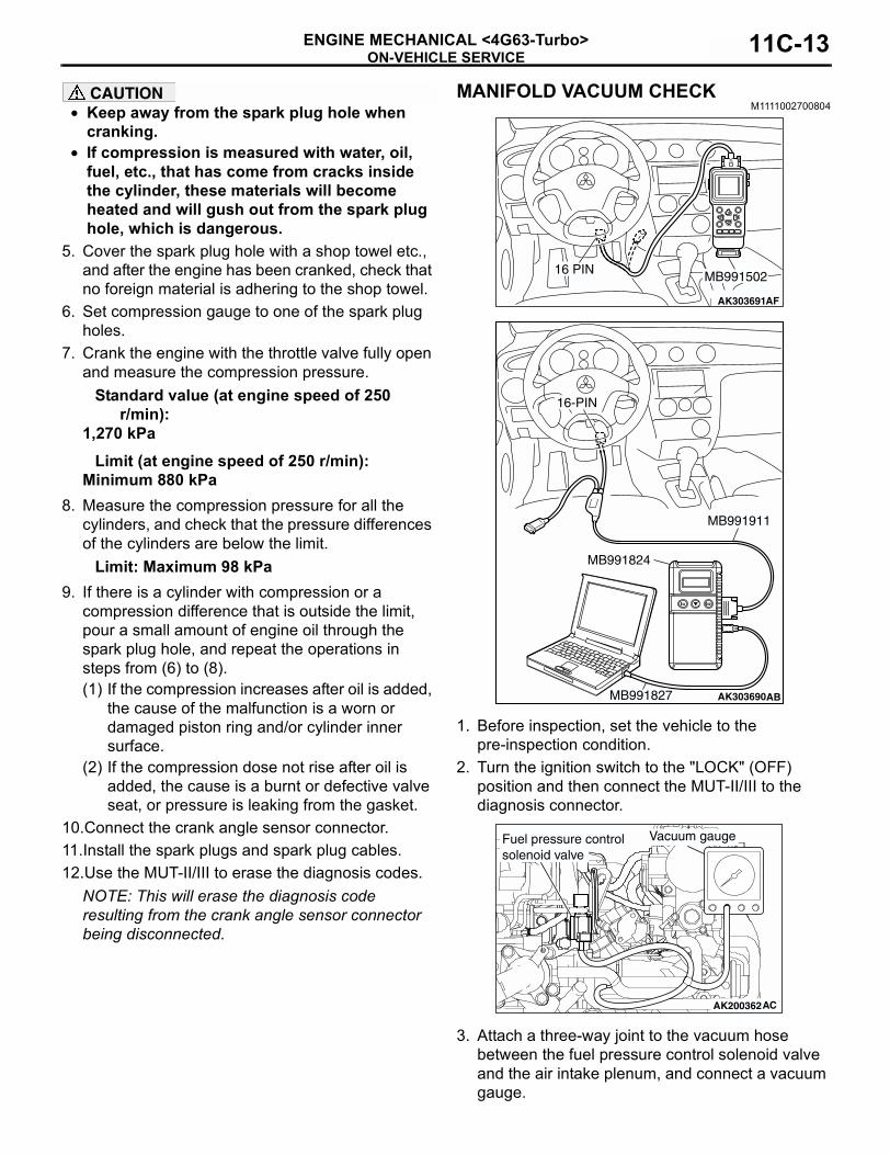
MANIFOLD VACUUM CHECKM1111002700804
1. Before inspection, set the vehicle to the pre-inspection condition.
2. Turn the ignition switch to the "LOCK" (OFF) position and then connect the MUT-II/III to the diagnosis connector.
3. Attach a three-way joint to the vacuum hose between the fuel pressure control solenoid valve and the air intake plenum, and connect a vacuum gauge.
AK303691AF
MB99150216 PIN
AK303690AB
MB991911
16-PIN
MB991827
MB991824
AK200362AC
Vacuum gaugeFuel pressure controlsolenoid valve

ON-VEHICLE SERVICEENGINE MECHANICAL <4G63-Turbo>11C-14
4. Start the engine and check that idle speed is within the standard valve.
Standard value: 750 ± 100 r/min5. Check the intake manifold vacuum.
Limit: Minimum 60 kPa6. Turn off the ignition switch.7. Remove the vacuum gauge and the three-way
joint, and then connect the vacuum hose.8. Turn the ignition switch to the "LOCK" (OFF)
position and then remove the MUT-II/III.
LASH ADJUSTER CHECKM1111002900563
If an abnormal noise (knocking) that seems to be coming from the lash adjuster is heard after starting the engine and dose not stop, carry out the following check.NOTE: .
• The abnormal noise which is caused by a prob-lem with the lash adjusters is generated after the engine is started, and will vary according to the engine speed. However, this noise is not related to the actual engine load.
Because of this, if the noise dose not occur immedi-ately after the engine is started, if it dose not change in accordance with the engine speed, or if it changes in accordance with the engine load, the source of the noise is not the lash adjusters.
• If there is a problem with the lash adjusters, the noise will almost never disappear, even if the engine has been run at idle to let it warm up.
The only case where the noise might disappear is if the oil in the engine has not been looked after properly and oil sludge has caused the lash adjusters to stick.
1. Start the engine.2. Check that the noise occurs immediately after the
engine is started, and that the noise changes in accordance with changes in the engine speed.If the noise dose not occur immediately after the engine is started, or if it dose not change in accordance with the engine speed, the problem is not being caused by the lash adjusters, so check for some other cause of the problem. Moreover, if the noise dose not change in accordance with the engine speed, the cause of the problem is probably not with the engine (In these cases, the lash adjusters are normal).
3. While the engine is idling, check that the noise level does not change when the engine load is varied.If the noise level changes, the cause of the noise is probably parts striking because of worn crankshaft bearings or connecting rod bearings (In such cases, the lash adjusters are normal).
4. After the engine has warmed up, run it at idle and check if any noise can be heard.If the noise has become smaller or disappeared, oil sludge could make the lash adjusters stick. Clean the lash adjusters (Refer to GROUP 11D − Rocker Arms and Camshaft − Inspection P.11D-37). If not improved, go to step 5.
5. Bleed air from the lash adjusters (Refer to P.11C-14).
6. If the noise has not disappeared even after the air bleeding, clean the lash adjusters (Refer to GROUP 11D − Rocker Arms and Camshaft − Inspection P.11D-37).
<LASH ADJUSTER AIR BLEEDING>NOTE: .
• If the vehicle is parked on a slope fir a long period of time, the amount of oil inside the lash adjuster will decrease, and air may get into the high pres-sure chamber when starting the engine.
• After parking the vehicle for long periods, the oil drains out of the oil passage, and it takes time for the oil to be supplied to the lash adjuster, so air can get into the high-pressure chamber.
• If either of the above situations occur, the abnor-mal noise can be eliminated by bleeding the air from inside the lash adjusters.
1. Check the engine oil and replenish or replace the oil if necessary.
AKX00328
Good
Min.
Max
AE

ON-VEHICLE SERVICEENGINE MECHANICAL <4G63-Turbo> 11C-15
NOTE: .• If there is an only small amount of oil, air will
be drawn in through the oil screen and will get into the oil passage.
• If the amount of oil is greater than normal, then the oil will being mixed by the crankshaft and a large amount of air may get mixed into the oil.
• If the oil is degenerated, air and oil will not separate easily in oil, and the amount of air mixed into the oil will increase.
• If the air which has been mixed in with the oil due to any of the above reasons gets into the high pressure chamber of the lash adjuster, the air inside the high pressure chamber will be compressed when the valve is open and the lash adjuster will over-compress, resulting in abnormal noise when the valve close. This is the same effect as if the valve clearance is adjusted to be too large by mistake. If the air inside the lash adjusters is then released, the operation of the lash adjusters will return to normal.
2. Run the engine at idle for 1 − 3 minutes to let it warm up.
3. With no load on the engine, repeat the drive pattern shown in the illustration above and check if the abnormal noise disappears (The noise should normally disappear after 10 − 30 repetitions, but if there is no change in the noise level after 30 repetitions or more, the problem is probably not due to air inside the lash adjusters).
4. After the noise has disappeared, repeat the drive pattern shown in the illustration above a further 5 times.
5. Run the engine at idle for 1 − 3 minutes and check that the noise has disappeared.
AK100001High-pressure chamber
AC
AKX00330
Gradually openthe throttle valve Close the throttle valve
Approximately3,000 r/min
Idle speed
Once
15 s 15 s
Drive pattern for air breeding
AE

CRANKSHAFT PULLEYENGINE MECHANICAL <4G63-Turbo>11C-16
CRANKSHAFT PULLEYREMOVAL AND INSTALLATION
M1112001600670
REMOVAL SERVICE POINT<<A>> DRIVE BELT REMOVALThe following operations will be needed due to the introduction of the serpentine drive system with the drive belt auto-tensioner.
1. Securely insert the spindle handle or ratchet handle with a 12.7 mm insertion angle into the jig hole of the auto-tensioner.
2. Rotate the auto-tensioner anti-clockwise and align hole A with hole B.CAUTION
To reuse the drive belt, draw an arrow indicating the rotating direction (clockwise) on the back of the belt using chalk, etc.
3. Insert an L-shaped hexagon wrench, etc. into the hole to fix and then remove the drive belt.
Pre-removal Operation• Under Cover Removal (Refer to GROUP 51, Under Cover
P.51-29).
Post-installation Operation• Drive Belt Tension Check (Refer to P.11A-8).• Under Cover Installation (Refer to GROUP 51, Under
Cover P.51-29).
AC401176AB
25 ± 4 N·m
1
2
Removal steps<<A>> 1. Drive belt
2. Crank shaft damper pulley
AC301703
AC301704AB
Hole A
Auto-tensioner
Hole B
AC301705AB
L-shapedhexagonwrench
Auto-tensioner

CAMSHAFT AND VALVE STEM SEALENGINE MECHANICAL <4G63-Turbo> 11C-17
CAMSHAFT AND VALVE STEM SEALREMOVAL AND INSTALLATION
M1112006600482
CAUTION*Remove and assemble the marked parts in each cylinder unit.
Pre-removal Operation• Engine Coolant Draining (Refer to GROUP 14, On-vehicle
Service − Engine Coolant Replacement P.14-17).• Intercooler Removal (Refer to GROUP 15, Intercooler
P.15-9).• Air Cleaner Removal (Refer to GROUP 15, Air Cleaner
P.15-7).• Accelerator Cable Removal (Refer to GROUP 17, Accel-
erator Cable and Pedal P.17-8).• Battery Removal• Valve Timing Belt Removal (Refer to P.11C-34).
Post-installation Operation• Valve Timing Belt Installation (Refer to P.11C-34).• Battery Installation• Accelerator Cable Installation (Refer to GROUP 17,
Accelerator Cable and Pedal P.17-8).• Air Cleaner Installation (Refer to GROUP 15, Air Cleaner
P.15-7).• Intercooler Installation (Refer to GROUP 15, Intercooler
P.15-9).• Engine Coolant Refilling (Refer to GROUP 14, On-vehicle
Service − Engine Coolant Replacement P.14-17).• Accelerator Cable Adjustment (Refer to GROUP 17,
On-vehicle Service − Accelerator Cable Check and Adjustment P.17-6).
• Drive Belt Tension Check (Refer to P.11A-8).
AC401177
1
1412
11
10
9
87
13
6
5
N
AB
4
N
3.0 ± 0.5 N·m11 ± 1 N·m
11 ± 1 N·m
3.5 ± 0.5 N·m
3.5 ± 0.5 N·m
11 ± 1 N·m
11 ± 1 N·m
11 ± 1 N·m
2
3
10.5 ± 0.5 N·m
4

CAMSHAFT AND VALVE STEM SEALENGINE MECHANICAL <4G63-Turbo>11C-18
Removal steps1. Rocker cover centre cover• Spark plug cables and ignition coils
(Refer to GROUP 16, Ignition Coil P.16-44.)
2. Oxygen sensor (front) connector3. Crank angle sensor connector4. Control wiring harness connection5. Camshaft position sensor
connector6. Capacitor connector
7. Rocker cover breather hose8. Rocker cover PCV hose9. Vacuum hose and pipe assembly
>>N<< 10. Rocker cover>>M<< 11. Camshaft end seal
12. Spark plug hole gaskets>>L<< 13. Rocker cover gasket
<<A>> >>K<< 14. Radiator upper hose connection
Removal steps (Continued)
AC401570
19
1817
1531
3029
28
27
32
AB
16 N
20N
35*34*
33*
36*N
35*34*33*
37* N
Apply engine oil to all moving parts beforeinstallation.
11 ± 1 N·m
21
2625
24 22
2320 ± 1 N·m
89 ± 9 N·m
14 ± 1 N·m
22 ± 4 N·m
10 ± 2 N·m
25 ± 4 N·m
38*
38*
Removal steps15. Camshaft position sensor support
cover16. Camshaft position sensor support
cover gasket>>J<< 17. Camshaft position sensing cylinder>>I<< 18. Camshaft position sensor support
<<B>> >>H<< 19. Camshaft sprockets>>G<< 20. Camshaft oil seals>>F<< 21. Camshaft bearing caps, front>>F<< 22. Camshaft bearing caps, rear>>F<< 23. Camshaft bearing caps, No.2>>F<< 24. Camshaft bearing caps, No.5>>F<< 25. Camshaft bearing caps, No.3
>>F<< 26. Camshaft bearing caps, No.4>>E<< 27. Inlet camshaft>>E<< 28. Exhaust camshaft
29. Rocker arms>>D<< 30. Rocker arm lash adjusters
31. Oil delivery body32. Spark plugs
<<C>> >>C<< 33. Valve spring retainer locks34. Valve spring retainers
>>B<< 35. Valve springs>>A<< 36. Inlet valve stem seals>>A<< 37. Exhaust valve stem seals
38. Valve spring seats
Removal steps (Continued)

CAMSHAFT AND VALVE STEM SEALENGINE MECHANICAL <4G63-Turbo> 11C-19
LUBRICATION AND SEALING POINTS
<The bottom view of the rocker cover>
Sealant: MITSUBISHI GENUINE PART MD970389 or equivalent
Engine oil
(Lip section)
10 mm
10 mm10 mm
<View A>
Sealant: 3M ATD Part No.8660 or equivalent
10 mm10 mm
Rockercover
Cylinderhead
φ 3 mm
AC211726
AA
A
Sealant: MITSUBISHI GENUINE PART MD970389 or equivalent
Sealant: MITSUBISHI GENUINE PART MD970389 or equivalent
Sealant: MITSUBISHI GENUINE PART MD970389 or equivalent
<Top view of cylinder head>

CAMSHAFT AND VALVE STEM SEALENGINE MECHANICAL <4G63-Turbo>11C-20
REMOVAL SERVICE POINTS<<A>> RADIATOR UPPER HOSE DISCON-NECTION
Make mating marks on the radiator hose and the hose clamp. Disconnect the radiator hose.
<<B>> CAMSHAFT SPROCKETS REMOVAL
1. Hold the hexagon part of the camshaft with a wrench.
2. Loosen the camshaft sprocket mounting bolts and remove the camshaft sprocket.
<<C>> VALVE SPRING RETAINER LOCKS REMOVAL
CAUTIONWhen removing valve spring retainer locks, leave the piston of each cylinder in the TDC (Top Dead Centre) position. The valve may fall into the cylin-der if the piston is not properly in the TDC posi-tion.
Use special tool valve spring compressor (MD998772) to compress the valve spring, remove the valve spring retainer locks.
INSTALLATION SERVICE POINTS>>A<< EXHAUST VALVE STEM SEALS/INLET VALVE STEM SEALS INSTALLATION
1. Check the valve stem seal colour to identify the inlet side or exhaust side.
2. Apply a small amount of engine oil to the valve stem seals.
AC200641AC
Mating marks
AC201457AB
AC201799
MD998772
AB
AC201542ABExhaust sideInlet side
Grey Grey green

CAMSHAFT AND VALVE STEM SEALENGINE MECHANICAL <4G63-Turbo> 11C-21
CAUTION• Valve stem seals cannot be reused.• The special tool valve stem seal installer
(MD998737) must be used to install the valve stem seal. Improper installation could result in oil leaking past the valve guide.
3. Use special tool to fill a new valve stem seal in the valve guide using the valve stem area as a guide.
>>B<< VALVE SPRINGS INSTALLATION
Install the valve springs with its identification colour painted end facing the locker arm.
>>C<< VALVE SPRING RETAINER LOCKS INSTALLATION
Use special tool valve spring compressor (MD998772) to compress the valve spring in the same manner as removal.
>>D<< ROCKER ARM LASH ADJUSTERS INSTALLATION
CAUTIONIf the rocker arm lash adjuster is reused, always clean and check it before installation. (Refer to GROUP 11D, Rocker Arms and Camshaft − Inspection P.11D-37).
>>E<< EXHAUST CAMSHAFT/INLET CAMSHAFT INSTALLATION1. Remove sealant remained on the cylinder head.2. Apply engine oil to the cam and the journal of the
camshaft.CAUTION
Do not install wrong camshaft at the side of inlet or exhaust. The exhaust camshaft has a slit at the rear surface.3. Install the camshaft to the cylinder head.
>>F<< CAMSHAFT BEARING CAPS, NO. 4/CAMSHAFT BEARING CAPS, NO. 3/CAMSHAFT BEARING CAPS, NO. 5/CAMSHAFT BEARING CAPS, NO. 2/CAMSHAFT BEARING CAPS, REAR/CAMSHAFT BEARING CAPS, FRONT INSTALLATION
1. Set the dowel pin of the camshaft to the position as shown in the illustration.
AC308920AB
MD998737
Valve
Valve stemseal
Valve guide
AC201453AB
Rocker arm side
Identificationcolour
AC201799
MD998772
AB
AC201458AB
Engine front
Slit
Exhaust camshaft
AC201459AB
Dowel pin
Exhaust sideInlet side
Approximately 3˚

CAMSHAFT AND VALVE STEM SEALENGINE MECHANICAL <4G63-Turbo>11C-22
2. Since the shape of camshaft bearing caps No.2 − 5 is identical, check the identification marks so that the bearing cap No., inlet side, or exhaust side cannot be mistaken to install to the direction as shown in the illustration.
Identification mark (engraved on the front and bearing caps No.2 − 5)
I: Inlet sideE: Exhaust side
3. Apply sealant to the positions (6 areas) of the upper side of the cylinder head as shown in the illustration.
Specified sealant: MITSUBISHI GENUINE PART MD970389 or equivalent
NOTE: Install the camshaft bearing caps, rear and camshaft bearing caps, front within 15 minutes after applying liquid gasket.
4. Position the camshaft bearing caps, rear in the direction as shown in the illustration for installation.
5. Check the identification marks on the camshaft bearing caps, front so that inlet side and exhaust side cannot be mistaken in the same way as that of bearing caps No.2 − 5.CAUTION
Then wait at least one hour. Never start the engine or let engine oil or coolant touch the adhesion surface during that time.6. Tighten the bearing cap mounting bolts increasing
the pressure in 2 to 3 times and finally tighten to the specified torque.
Tightening torque: 20 ± 1 N⋅m7. Ensure that the rocker arms are installed properly.
NOTE: Remove an excess of sealant completely.
>>G<< CAMSHAFT OIL SEALS INSTALLATION
1. Apply engine oil to the entire inner diameter of the oil seal lip.
2. Use special tool camshaft oil seal installer (MD998713) to press-fit the oil seals.
>>H<< CAMSHAFT SPROCKETS INSTALLATION
1. Hold the hexagon part of the camshaft with a wrench in the same manner as removal.
AC201460
E 4
AB
Bearing cap No.
Identification ofinlet side and exhaust side
Engine front
AC201461AB
Engine front
AC201462AB
Front markingEngine front
AC102323ABMD998713
AC201457AB
CAMSHAFT AND VALVE STEM SEALENGINE MECHANICAL <4G63-Turbo> 11C-23
2. Tighten the camshaft sprocket mounting bolts to the specified torque.
Tightening torque: 89 ± 9 N⋅m
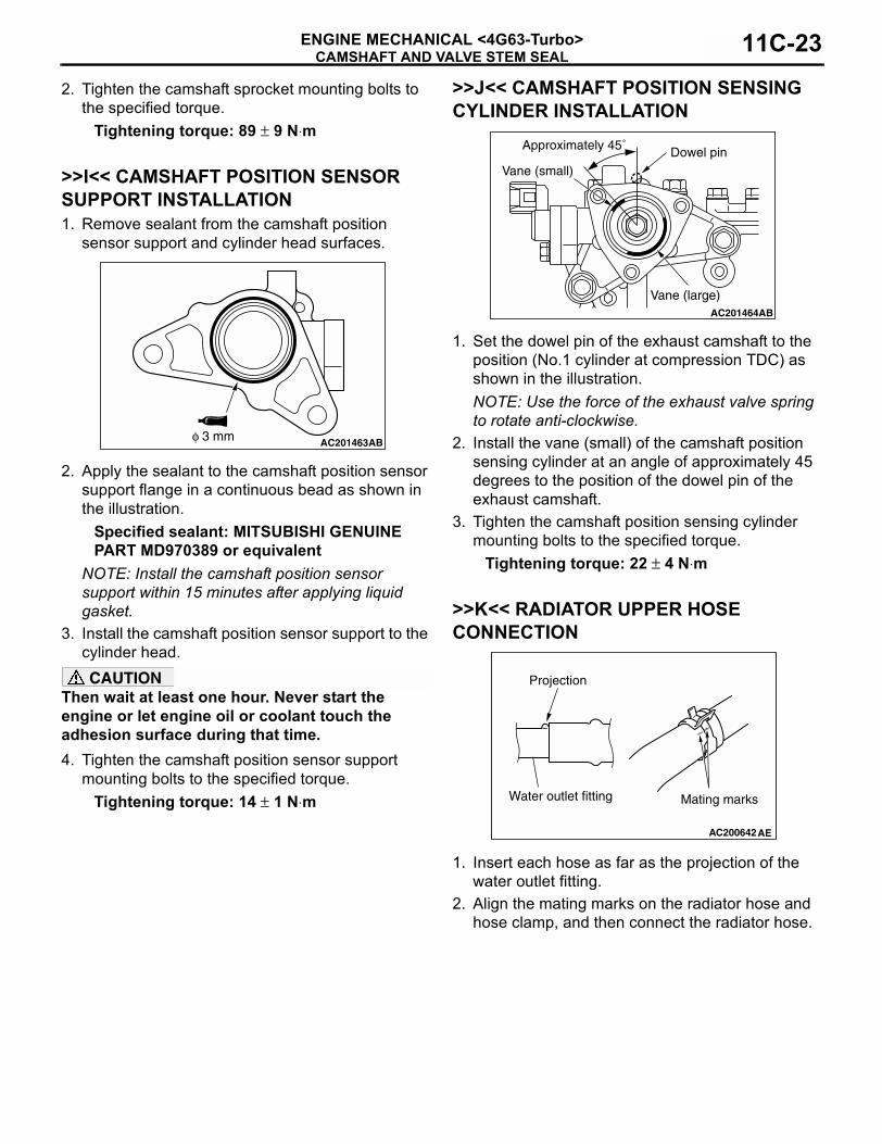
>>I<< CAMSHAFT POSITION SENSOR SUPPORT INSTALLATION1. Remove sealant from the camshaft position
sensor support and cylinder head surfaces.
2. Apply the sealant to the camshaft position sensor support flange in a continuous bead as shown in the illustration.
Specified sealant: MITSUBISHI GENUINE PART MD970389 or equivalent
NOTE: Install the camshaft position sensor support within 15 minutes after applying liquid gasket.
3. Install the camshaft position sensor support to the cylinder head.CAUTION
Then wait at least one hour. Never start the engine or let engine oil or coolant touch the adhesion surface during that time.4. Tighten the camshaft position sensor support
mounting bolts to the specified torque.Tightening torque: 14 ± 1 N⋅m
>>J<< CAMSHAFT POSITION SENSING CYLINDER INSTALLATION
1. Set the dowel pin of the exhaust camshaft to the position (No.1 cylinder at compression TDC) as shown in the illustration.NOTE: Use the force of the exhaust valve spring to rotate anti-clockwise.
2. Install the vane (small) of the camshaft position sensing cylinder at an angle of approximately 45 degrees to the position of the dowel pin of the exhaust camshaft.
3. Tighten the camshaft position sensing cylinder mounting bolts to the specified torque.
Tightening torque: 22 ± 4 N⋅m
>>K<< RADIATOR UPPER HOSE CONNECTION
1. Insert each hose as far as the projection of the water outlet fitting.
2. Align the mating marks on the radiator hose and hose clamp, and then connect the radiator hose.
AC201463φ 3 mm AB
AC201464AB
Dowel pin
Vane (large)
Vane (small)
Approximately 45˚
AC200642
Mating marks
Projection
Water outlet fitting
AE
CAMSHAFT AND VALVE STEM SEALENGINE MECHANICAL <4G63-Turbo>11C-24
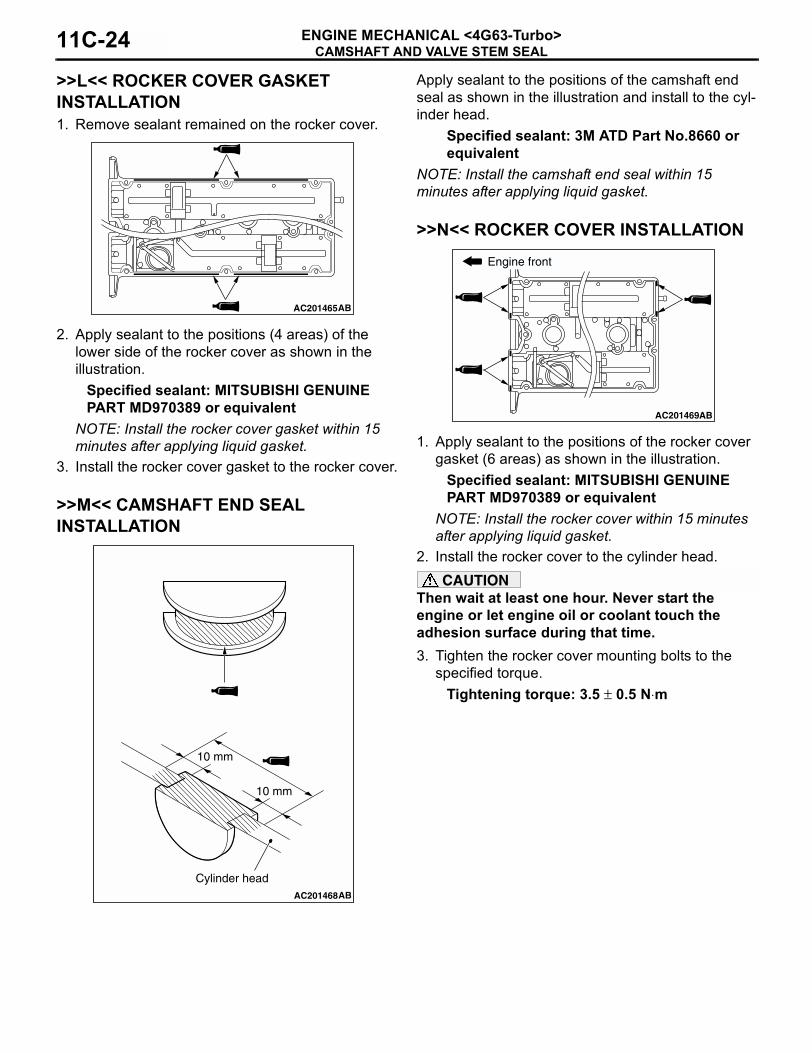
>>L<< ROCKER COVER GASKET INSTALLATION1. Remove sealant remained on the rocker cover.
2. Apply sealant to the positions (4 areas) of the lower side of the rocker cover as shown in the illustration.
Specified sealant: MITSUBISHI GENUINE PART MD970389 or equivalent
NOTE: Install the rocker cover gasket within 15 minutes after applying liquid gasket.
3. Install the rocker cover gasket to the rocker cover.
>>M<< CAMSHAFT END SEAL INSTALLATION
Apply sealant to the positions of the camshaft end seal as shown in the illustration and install to the cyl-inder head.
Specified sealant: 3M ATD Part No.8660 or equivalent
NOTE: Install the camshaft end seal within 15 minutes after applying liquid gasket.
>>N<< ROCKER COVER INSTALLATION
1. Apply sealant to the positions of the rocker cover gasket (6 areas) as shown in the illustration.
Specified sealant: MITSUBISHI GENUINE PART MD970389 or equivalent
NOTE: Install the rocker cover within 15 minutes after applying liquid gasket.
2. Install the rocker cover to the cylinder head.CAUTION
Then wait at least one hour. Never start the engine or let engine oil or coolant touch the adhesion surface during that time.3. Tighten the rocker cover mounting bolts to the
specified torque.Tightening torque: 3.5 ± 0.5 N⋅m
AC201465AB
AC201468
Cylinder head
10 mm
10 mm
AB
AC201469
Engine front
AB

OIL PANENGINE MECHANICAL <4G63-Turbo> 11C-25
OIL PANREMOVAL AND INSTALLATION
M1112002800989
Pre-removal Operation• Under Cover Removal (Refer to GROUP 51, Under Cover
P.51-29).• Engine Oil Draining (Refer to GROUP 12, On-vehicle
Service − Engine Oil Replacement P.12-3).• Front Exhaust Pipe Removal (Refer to GROUP 15,
Exhaust Pipe and Main Muffler P.15-29).• Centre Member Removal (Refer to GROUP 32, Engine
Roll Stopper and Centre Member P.32-11).• Starter Assembly Removal (Refer to GROUP 16, Starter
Motor Assembly P.16-26).
Post-installation Operation• Starter Assembly Installation (Refer to GROUP 16, Starter
Motor Assembly P.16-26).• Centre Member Installation (Refer to GROUP 32, Engine
Roll Stopper and Centre Member P.32-11).• Front Exhaust Pipe Installation (Refer to GROUP 15,
Exhaust Pipe and Main Muffler P.15-29).• Engine Oil Refilling (Refer to GROUP 12, On-vehicle
Service − Engine Oil Replacement P.12-3).• Under Cover Installation (Refer to GROUP 51, Under
Cover P.51-29).
AC401138
8
N 9
11
103
4
AB
9.0 ± 3.0 N·m
9.0 ± 1.0 N·m
9.0 ± 3.0 N·m39 ± 5 N·m
2
1N
1N
48 ± 7 N·m
48 ± 7 N·m
12 ± 2 N·m
22 ± 4 N·m
9.0 ± 3.0 N·m
44 ± 10 N·m
6 N
14 ± 1 N·m
9.0 ± 1.0 N·m
7N
5
Removal steps1. Engine oil cooler tube gaskets2. Engine oil cooler hose and bracket
assembly>>D<< 3. Transmission housing front lower
cover stay4. Flywheel housing front lower cover5. Oil return tube6. Oil return tube gasket
7. Oil return tube gasket8. Engine oil pan drain plug
>>C<< 9. Engine oil pan drain plug gasket<<A>> >>B<< 10. Engine lower oil pan<<B>> >>A<< 11. Engine upper oil pan
Removal steps (Continued)

OIL PANENGINE MECHANICAL <4G63-Turbo>11C-26
REMOVAL SERVICE POINTS<<A>> ENGINE LOWER OIL PAN REMOVAL1. Remove the engine lower oil pan mounting bolts.
CAUTIONDo not use special tool oil pan FIPG cutter (MD998727). The engine upper oil pan is made of aluminium and this tool will damage it.
2. Apply a piece of wood to the lower oil pan and strike it with a hammer to remove the engine lower oil pan.
<<B>> ENGINE UPPER OIL PAN REMOVAL1. Remove the engine upper oil pan mounting bolts.
CAUTIONDo not use special tool oil pan FIPGcutter (MD998727). The engine upper oil pan is made of aluminium and this tool will damage it.
2. Screw in the bolt into bolt hole A in the location shown. Then lift the upper oil pan and remove it.
INSTALLATION SERVICE POINTS>>A<< ENGINE UPPER OIL PAN INSTAL-LATION1. Remove sealant from the engine upper oil pan
and cylinder block surfaces.
2. Apply a bead of the sealant to the mating surface of the engine upper oil pan as shown.
Specified sealant: MITSUBISHI GENUINE PART MD970389 or equivalent
NOTE: Install the engine upper oil pan within 15 minutes after applying sealant.
3. Assemble the engine upper oil pan to the cylinder block.CAUTION
Then wait at least one hour. Never start the engine or let engine oil or coolant touch the seal-ant surface during that time.
AC102931ABEngine lower oil pan
AC401139 AB
AA
AC401140AB
φ 4 mm
Bolt hole portionGroove portion
AC401141AB
B
B
B
B
B
B
BBB
B
B
B
B
B
B
B
AA

OIL PANENGINE MECHANICAL <4G63-Turbo> 11C-27
4. Insert the bolts to the engine upper oil pan as shown, and tighten them to the specified torque.
NOTE: D: Nominal diameter, L: Nominal lengthTightening torque: 9.0 ± 3.0 N⋅m
>>B<< ENGINE LOWER OIL PAN INSTALLATION1. Remove sealant from the engine lower oil pan and
engine upper oil pan.
2. Apply a bead of the sealant to the mating surface of the engine lower oil pan as shown.
Specified sealant: MITSUBISHI GENUINE PART MD970389 or equivalent
NOTE: Install the engine lower oil pan within 15 minutes after applying sealant.
3. Assemble the engine lower oil pan to the engine upper oil pan.CAUTION
Then wait at least one hour. Never start the engine or let engine oil or coolant touch the seal-ant surface during that time.
4. Insert the bolts to the engine lower oil pan as shown, and tighten them to the specified torque in the order shown.
NOTE: D: Nominal diameter, L: Nominal lengthTightening torque: 9.0 ± 3.0 N⋅m
>>C<< ENGINE OIL PAN DRAIN PLUG GASKET INSTALLATION
Replace the gasket with a new one. Install the new gasket in the direction shown in the illustration.
>>D<< TRANSMISSION HOUSING FRONT LOWER COVER STAY INSTALLATIONInstall the transmission housing front lower cover stay in the following order.1. Tighten the engine side four mounting bolts to the
specified torque.Tightening torque: 22 ± 4 N⋅m
2. Tighten the transmission side two mounting bolts to the specified torque.
Tightening torque: 44 ± 10 N⋅m
INSPECTIONM1112002900210
• Check the oil pan for cracks.• Check the oil pan sealant-coated surface for
damage and deformation.
Name Symbol Quantity Size mm (D × L)
Flange bolt A 2 M6 × 16B 16 M6 × 18
AC401142AB
φ 4 mm
Bolt hole portionGroove portion
AC401143AB
A-3
B-6
B-7
B-10B-11B-1
B-4
B-5
B-12 B-2
B-8
B-9
Name Symbol Quantity Size mm (D × L)
Flange bolt A 1 M6 × 75B 11 M6 × 10
AC102325AF
Engine lower oil pan side

CRANKSHAFT OIL SEALENGINE MECHANICAL <4G63-Turbo>11C-28
CRANKSHAFT OIL SEALREMOVAL AND INSTALLATION
M1112003100552
REMOVAL SERVICE POINT<<A>> FLYWHEEL BOLTS REMOVAL
1. Use special tool flywheel stopper (MD998781) to secure the flywheel.
2. Remove the flywheel mounting bolts.
AC401178 AB
1
2
Engine oil
3 6
5
4
(Lip section)
6 N
3N
132 ± 5 N·m
(Lip section)
Crankshaft front oil seal removal steps
• Valve timing belt, balancer timing belt (Refer to P.11C-34).
>>D<< 1. Crankshaft balancer shaft drive sprocket
2. Crankshaft key>>C<< 3. Crankshaft front oil seal
Crankshaft front oil seal removal steps
• Transfer assembly (Refer to GROUP 22A, Transfer Assembly P.22A-11).
• Transmission assembly (Refer to GROUP 22A, Transmission Assembly P.22A-13).
<<A>> >>B<< 4. Flywheel bolts5. Flywheel assembly
>>A<< 6. Crankshaft rear oil seal
AC211171AB
MD998781

CRANKSHAFT OIL SEALENGINE MECHANICAL <4G63-Turbo> 11C-29
INSTALLATION SERVICE POINTS>>A<< CRANKSHAFT REAR OIL SEAL INSTALLATION
1. Apply a small amount of engine oil to the entire inner diameter of the oil seal lip.
2. Use the following special tools to press-fit the oil seal.
• Installer bar (MB990938)• Crankshaft rear oil seal installer (MD998776)
>>B<< FLYWHEEL BOLTS INSTALLATION
1. Use special tool flywheel stopper (MD998781) to secure the flywheel in the same manner as removal.
2. Tighten the flywheel mounting bolts to the specified torque.
Tightening torque: 132 ± 5 N⋅m
>>C<< CRANKSHAFT FRONT OIL SEAL INSTALLATION
1. Apply a small amount of engine oil to the entire inner diameter of the oil seal lip.
2. Apply a small amount of engine oil to the outer diameter of special tool crankshaft front oil seal guide (MD998285) and install it to the crankshaft.
3. Use special tool crankshaft front oil seal installer (MD998375) to press-fit the oil seal.
>>D<< CRANKSHAFT BALANCER SHAFT DRIVE SPROCKET INSTALLATION
1. Clean or degrease the front case, the crankshaft and the crankshaft balancer shaft drive sprocket as shown.NOTE: Also clean the degreased surfaces.
2. Install the crankshaft balancer shaft drive sprocket in the direction shown in the illustration.
AC102328AB
Oil seal
MB990938
MD998776 Crankshaft
(Engine oil)
AC211171AB
MD998781
AC102329AC
MD998285
(Engine oil)
(Oil applied to thecircumference)
Oil seal
Crankshaft MD998375
AC211222
Crankshaftbalancershaftdrive sprocket
Engine front
Front case
Crankshaft
AB
: Clean: Clean and degrease

CYLINDER HEAD GASKETENGINE MECHANICAL <4G63-Turbo>11C-30
CYLINDER HEAD GASKETREMOVAL AND INSTALLATION
M1112004001205
Pre-removal Operation• Fuel Line Pressure Reduction [Refer to GROUP 13B,
On-vehicle Service − Fuel Pump Connector Disconnec-tion (How to Reduce Pressurized Fuel Lines) P.13B-381].
• Under Cover Removal (Refer to GROUP 51, Under Cover P.51-29).
• Engine Oil Draining (Refer to GROUP 12, On-vehicle Service − Engine Oil Replacement P.12-3).
• Engine Coolant Draining (Refer to GROUP 14, On-vehicle Service − Engine Coolant Replacement P.14-17).
• Intercooler Removal (Refer to GROUP 15, Intercooler P.15-9).
• Air Cleaner Removal (Refer to GROUP 15, Air Cleaner P.15-7).
• Accelerator Cable Removal (Refer to GROUP 17, Accel-erator Cable and Pedal P.17-8).
• Battery Removal• Rocker Cover Center Cover Removal (Refer to
P.11C-17).• Valve Timing Belt Removal (Refer to P.11C-34).
Post-installation Operation• Valve Timing Belt Installation (Refer to P.11C-34).• Rocker Cover Center Cover Installation (Refer to
P.11C-17).• Battery Installation• Accelerator Cable Installation (Refer to GROUP 17,
Accelerator Cable and Pedal P.17-8).• Air Cleaner Installation (Refer to GROUP 15, Air Cleaner
P.15-7).• Intercooler Installation (Refer to GROUP 15, Intercooler
P.15-9).• Engine Coolant Refilling (Refer to GROUP 14, On-vehicle
Service − Engine Coolant Replacement P.14-17).• Engine Oil Refilling (Refer to GROUP 12, On-vehicle
Service − Engine Oil Replacement P.12-3).• Accelerator Cable Adjustment (Refer to GROUP 17,
On-vehicle Service − Accelerator Cable Check and Adjustment P.17-6).
• Drive Belt Tension Check (Refer to P.11A-8).• Under Cover Installation (Refer to GROUP 51, Under
Cover P.51-29).• Fuel Leak Check
AC401179
3
8
76
4
6
13 ± 1 N·m
AB
5N(Engine oil)
29.0 ± 2.0 N·m
9.0 ± 2.0 N·m 1

CYLINDER HEAD GASKETENGINE MECHANICAL <4G63-Turbo> 11C-31
Removal steps1. Control wiring harness connection2. Earth cable connection3. Brake booster vacuum hose
connection
4. Engine oil level gauge and guide assembly
5 O-ring6. Canister vacuum hose connection
Removal steps (Continued)
AC401180
5.0 ± 1.0 N·m
(Engine oil)
13
1211
10
9
8
7
16
14 N (Engine oil)
31 ± 3 N·m
11 ± 1 N·m
17 N
AB
15
22 ± 4 N·m
<Cold engine>78 ± 2 N·m → 0 N·m → 20 ± 2 N·m → +90˚ → +90˚
Removal steps7. Alternator brace bolt8. Detonation sensor connection9. Battery wiring harness connection10. Inlet manifold stay• Water outlet fitting and thermostat
case assembly (Refer to GROUP 14, Water Hose and Water Pipe P.14-29).
• Turbocharger assembly (Refer to GROUP 15, Exhaust Manifold and Turbocharger P.15-21).
• Rocker cover (Refer to P.11C-17).11. Heater water hose connection12. Fuel return line hose connection
>>C<< 13. Fuel high-pressure hose connection
>>C<< 14. O-ring<<A>> >>B<< 15. Cylinder head bolts
16. Cylinder head assembly>>A<< 17. Cylinder head gasket
Removal steps (Continued)

CYLINDER HEAD GASKETENGINE MECHANICAL <4G63-Turbo>11C-32
REMOVAL SERVICE POINT<<A>> CYLINDER HEAD BOLTS REMOVAL
Using special tool cylinder head bolt wrench (MB991654), loosen the cylinder head bolts in two or three steps in the order of the numbers shown in the illustration.NOTE: If the cylinder head bolts cannot be pulled out due to the washer being trapped in the valve spring, raise the bolt slightly, then remove it while holding it by using a magnet.
INSTALLATION SERVICE POINTS>>A<< CYLINDER HEAD GASKET INSTALLATION
CAUTIONDo not allow any foreign materials to get into the coolant passages, oil passages and cylinder.1. Remove the gasket from the cylinder head and
cylinder block.
2. Assemble to the cylinder block so the cylinder head gasket identification mark "63" is at the top surface and on the exhaust side.
>>B<< CYLINDER HEAD BOLTS INSTALLATION
1. Check that the nominal length of each cylinder head bolt meets the limit. If it exceeds the limit, replace the bolt with a new one.
Limit (A): 99.4 mm2. Apply a small amount of engine oil to the thread of
the bolts and to the washers.
AC201623
MB991654
Engine front
1
2
4697
3 5 10 8
AB
AC107217AC
Identificationmark "63"
Exhaust side
AC102537
A
AB
(Engine oil)
CYLINDER HEAD GASKETENGINE MECHANICAL <4G63-Turbo> 11C-33
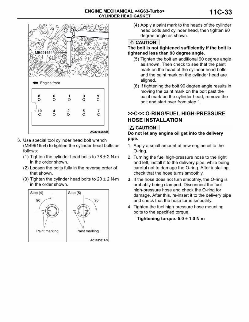
3. Use special tool cylinder head bolt wrench (MB991654) to tighten the cylinder head bolts as follows:(1) Tighten the cylinder head bolts to 78 ± 2 N⋅m
in the order shown.(2) Loosen the bolts fully in the reverse order of
that shown.(3) Tighten the cylinder head bolts to 20 ± 2 N⋅m
in the order shown.
(4) Apply a paint mark to the heads of the cylinder head bolts and cylinder head, then tighten 90 degree angle as shown.
CAUTIONThe bolt is not tightened sufficiently if the bolt is tightened less than 90 degree angle.
(5) Tighten the bolt an additional 90 degree angle as shown. Then check to see that the paint mark on the head of the cylinder head bolts and the paint mark on the cylinder head are aligned.
(6) If tightening the bolt 90 degree angle results in moving the paint mark on the bolt past the paint mark on the cylinder head, remove the bolt and start over from step 1.
>>C<< O-RING/FUEL HIGH-PRESSURE HOSE INSTALLATION
CAUTIONDo not let any engine oil get into the delivery pipe.1. Apply a small amount of new engine oil to the
O-ring.2. Turning the fuel high-pressure hose to the right
and left, install it to the delivery pipe, while being careful not to damage the O-ring. After installing, check that the hose turns smoothly.
3. If the hose does not turn smoothly, the O-ring is probably being clamped. Disconnect the fuel high-pressure hose and check the O-ring for damage. After this, re-insert it to the delivery pipe and check that the hose turns smoothly.
4. Tighten the fuel high-pressure hose mounting bolts to the specified torque.
Tightening torque: 5.0 ± 1.0 N⋅m
AC201625
MB991654
10
9
7524
8 6 1 3
Engine front
AB
AC102331AB
Paint marking
90˚ 90˚
Step (4) Step (5)
Paint marking

TIMING BELTENGINE MECHANICAL <4G63-Turbo>11C-34
TIMING BELTREMOVAL AND INSTALLATION
M1112004301002
Pre-removal Operation• Under Cover Removal (Refer to GROUP 51, Under Cover
P.51-29.)• Crankshaft Shaft Damper Pulley Removal (Refer to
P.11C-16.)• Front Exhaust Pipe Removal (Refer to GROUP 15,
Exhaust Pipe and Main Muffler P.15-29.)• Starter Assembly Removal (Refer to GROUP 16, Starter
Motor Assembly P.16-26.)• Accelerator Cable Removal (Refer to GROUP 17, Accel-
erator Cable and Pedal P.17-8).
Post-installation Operation• Accelerator Cable Installation (Refer to GROUP 17,
Accelerator Cable and Pedal P.17-8).• Starter Assembly Installation (Refer to GROUP 16, Starter
Motor Assembly P.16-26.)• Front Exhaust Pipe Installation (Refer to GROUP 15,
Exhaust Pipe and Main Muffler P.15-29.)• Crankshaft Shaft Damper Pulley Installation (Refer to
P.11C-16.)• Drive Belt Tension Check (Refer to P.11A-8.)• Under Cover Installation (Refer to GROUP 51, Under
Cover P.51-29.)• Accelerator Cable Adjustment (Refer to GROUP 17,
On-vehicle Service − Accelerator Cable Check and Adjustment P.17-6).
AC401181
98
7
6
5
3
2
11 ± 1 N·m
8.8 ± 1.0 N·m
11 ± 1 N·m
23 ± 3 N·m
48 ± 5 N·m
79 ± 5 N·m
21 ± 4 N·m
9.0 ± 1.0 N·m
22 ± 4 N·m
44 ± 10 N·m
4
10
AB
1
Removal steps1. Control wiring harness connection2. Timing belt upper cover3. Water pump pulley4. Idler pulley5. Auto-tensioner6. Timing belt lower cover
• Engine mounting insulator (Refer to GROUP 32, Engine Mount P.32-7).
>>G<< • Valve timing belt tension adjustment
<<A>> >>F<< 7. Valve timing belt>>E<< 8. Timing belt tensioner pulley
Removal steps (Continued)
TIMING BELTENGINE MECHANICAL <4G63-Turbo> 11C-35
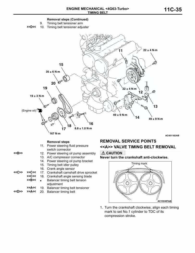
REMOVAL SERVICE POINTS<<A>> VALVE TIMING BELT REMOVAL
CAUTIONNever turn the crankshaft anti-clockwise.
1. Turn the crankshaft clockwise, align each timing mark to set No.1 cylinder to TDC of its compression stroke.
9. Timing belt tensioner arm>>D<< 10. Timing belt tensioner adjuster
Removal steps (Continued)
AC401182
2019
1817
16
15
14
12
13
35 ± 6 N·m
49 ± 9 N·m
22 ± 4 N·m
8.8 ± 1.0 N·m
167 N·m
19 ± 3 N·m
49 ± 9 N·m
22 ± 4 N·m
AB
(Engine oil)
11
Removal steps11. Power steering fluid pressure
switch connector<<B>> 12. Power steering oil pump assembly
13. A/C compressor connector14. Power steering oil pump bracket15. Timing belt idler pulley16. Crank angle sensor
<<C>> >>C<< 17. Crankshaft camshaft drive sprocket>>C<< 18. Crankshaft angle sensing blade>>B<< • Balancer timing belt tension
adjustment>>A<< 19. Balancer timing belt tensioner
<<D>> >>A<< 20. Balancer timing belt
AC102487
Timing mark

TIMING BELTENGINE MECHANICAL <4G63-Turbo>11C-36
2. Remove the timing belt under cover rubber plug and then set the special tool adjusting bolt (MD998738).CAUTION
The special tool can be gradually installed at a rate of a 30 degree turn per second. If it is screwed in all at once, the timing belt tensioner adjuster rod will not easily retract and the special tool may bend.
3. Screw in the special tool until it comes in contact with the timing belt tensioner arm.
4. Gradually screw in the special tool. Then align the timing belt tensioner adjuster rod set hole A with the timing belt tensioner adjustor cylinder set hole B.
5. Insert a wire or pin in the set hole.CAUTION
To reuse the valve timing belt, draw an arrow indicating the rotating direction (clockwise) on the back of the belt using chalk.6. After removal of adjusting bolt special tool, loosen
the timing belt tensioner pulley mounting bolt and remove the valve timing belt.
<<B>> POWER STEERING OIL PUMP ASSEMBLY REMOVALWith the hose installed, remove the power steering oil pump assembly from the bracket.NOTE: Secure the removed power steering oil pump assembly with cord or rope at a position where they will not interfere with the removal of the balancer tim-ing belt.
<<C>> CRANKSHAFT CAMSHAFT DRIVE SPROCKET REMOVAL
1. Use the following special tools to support the crankshaft camshaft drive sprocket.
• Special spanner (MB991367)• Pin (MB991385)
2. Loosen the crankshaft pulley centre bolt and remove the crankshaft camshaft drive sprocket.
AC102492AB
Timing belt under cover
MD998738
AC107289
MD998738
Timing belttensioner arm
AB
AC102775AB
AB
AC107185AC
Wire or pin
Timing belt tensioner pulleymounting bolt
AC102332AB
MB991385
MB991367
Crankshaftcamshaftdrive sprocket

TIMING BELTENGINE MECHANICAL <4G63-Turbo> 11C-37
<<D>> BALANCER TIMING BELT REMOVAL
CAUTIONTo reuse the balancer timing belt, draw an arrow indicating the rotating direction (clockwise) on the back of the belt using chalk.
INSTALLATION SERVICE POINTS>>A<< BALANCER TIMING BELT/BAL-ANCER TIMING BELT TENSIONER INSTALLATION
1. Ensure that the crankshaft balancershaft drive sprocket timing marks and balancershaft sprocket timing marks are aligned.
2. Install the balancer timing belt on the crankshaft balancershaft drive sprocket and balancershaft sprocket. There should be no slack on the tension side.
3. Assemble and temporarily fix the centre of the pulley of the balancer timing belt tensioner so that it is at the top left from the centre of the mounting bolt, and the pulley flange is at the front-side of the engine.
4. Adjust the balancer timing belt tension.
>>B<< BALANCER TIMING BELT TENSION ADJUSTMENT
CAUTIONWhen tightening the mounting bolt, ensure that the tensioner does not rotate with the bolt. Allow-ing it to rotate with the bolt can cause excessive tension of the belt.
1. With your fingers, lift the balancer timing belt tensioner in the direction of the arrow. Apply pressure of 3.0 ± 0.4 N⋅m to the balancer timing belt. Tighten the assembling bolt to the specified torque. Then, fix the balancer timing belt tensioner.
Tightening torque: 19 ± 3 N⋅m
2. Turn the crankshaft clockwise two turns to set No.1 cylinder to TDC of its compression stroke and check that the sprocket timing marks are aligned.
AC102689AB
Balancershaft sprocket
Belt tension side
Timing markTiming mark
Crankshaftbalancershaftdrive sprocket
AC102690AB
Centre ofthe pulley
Centre of the mounting bolt
AC102691
AC102689AC
Balancershaft sprocket
Timing markTiming mark
Crankshaftbalancershaftdrive sprocket
AC102693AB
Deflection
Approximately 100 N

TIMING BELTENGINE MECHANICAL <4G63-Turbo>11C-38
3. Apply a pressure of approximately 100N at the centre (arrow area) between the sprocket as shown, then inspect whether the belt deflection is within the standard value.
Standard value:At adjustment: 5 − 7 mmAt replacement: 5 − 7 mm
4. If not within the standard value, adjust the belt tension again.
>>C<< CRANKSHAFT ANGLE SENSING BLADE/CRANKSHAFT CAMSHAFT DRIVE SPROCKET INSTALLATION
1. Clean or degrease the crankshaft, the crankshaft angle sensing blade, the crankshaft camshaft drive sprocket and crankshaft pulley washer as shown.NOTE: Also clean the degreased surfaces.
2. Install the crankshaft angle sensing blade and crankshaft camshaft drive sprocket in the direction shown.
3. Place the larger chamfer side of the crank shaft pulley washer in the direction shown and then assemble on the crankshaft pulley centre bolt.
4. Apply some engine oil to the crankshaft pulley centre bolt bearing surface and screw.
5. Use the following special tool as during removal to support the crankshaft camshaft drive sprocket.
• Special spanner (MB991367)• Pin (MB991385)
6. Tighten the crankshaft pulley centre bolts to the specified torque.
Tightening torque: 167 N⋅m
>>D<< TIMING BELT TENSIONER ADJUSTER INSTALLATION1. Install according to the following procedures when
the timing belt tensioner adjuster rod is fully extended.CAUTION
If the compression is too fast, the procedure may damage the rod.
(1) Slowly compress the timing belt tensioner adjuster rod using a press or vice, then align the set hole A of the rod with set hole B of the timing belt tensioner adjuster cylinder.
AC211535AC
Crankshaft camshaft drive sprocket
Crankshaft pulley centre bolt
Crankshaft
Crankshaft angle sensing blade
Crankshaft pulley washer
Engine front
: Clean: Clean and degrease: Apply engine oil
AC102332AB
MB991385
MB991367
Crankshaftcamshaftdrive sprocket
AC102334AB
A B

TIMING BELTENGINE MECHANICAL <4G63-Turbo> 11C-39
(2) Insert a wire or pin into the aligned set hole.NOTE: When replacing the timing belt tensioner adjuster with new parts, the timing belt tensioner adjuster is set with a pin.
2. Assemble the timing belt tensioner adjuster to the engine, then tighten the assembling bolt to the specified torque. Do not remove the wire or pin until the tension of the valve timing belt is adjusted.
Tightening torque: 23 ± 3 N⋅m
>>E<< TIMING BELT TENSIONER PULLEY INSTALLATION
Temporarily tighten the timing belt tensioner pulley as shown.
>>F<< VALVE TIMING BELT INSTALLATION
1. Align the timing marks on the camshaft sprocket, crankshaft camshaft drive sprocket and engine oil pump sprocket.
2. Adjust the timing mark of the engine oil pump sprocket. Unplug the cylinder block plug. Insert a bolt (M6 sectional width 10 mm, minor diameter 45 mm) from the plug hole and then check. If the bolt comes in contact with the balancer shaft turn the sprocket one rotation. Re-adjust the timing mark and then check to see that the bolt fits. Do not remove the bolt until the valve timing belt is assembled.
3. Install the valve timing belt as follows:
AC102335AC
Wire or pin
AC102336AB
Timing belt tensionerpulley hole
AC102486
Crankshaft camshaftdrive sprocket Engine oil
pump sprocket
AC
Timing mark
Camshaft sprocket
Timing mark
Timing mark
AC201800 AB
Bolt
Cylinder block
Plug
Balancershaft
TIMING BELTENGINE MECHANICAL <4G63-Turbo>11C-40
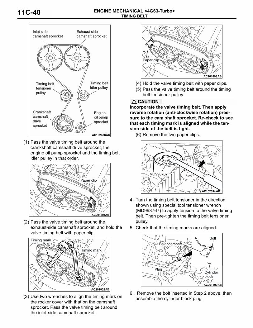
(1) Pass the valve timing belt around the crankshaft camshaft drive sprocket, the engine oil pump sprocket and the timing belt idler pulley in that order.
(2) Pass the valve timing belt around the exhaust-side camshaft sprocket, and hold the valve timing belt with paper clip.
(3) Use two wrenches to align the timing mark on the rocker cover with that on the camshaft sprocket. Pass the valve timing belt around the inlet-side camshaft sprocket.
(4) Hold the valve timing belt with paper clips.(5) Pass the valve timing belt around the timing
belt tensioner pulley.CAUTION
Incorporate the valve timing belt. Then apply reverse rotation (anti-clockwise rotation) pres-sure to the cam shaft sprocket. Re-check to see that each timing mark is aligned while the ten-sion side of the belt is tight.
(6) Remove the two paper clips.
4. Turn the timing belt tensioner in the direction shown using special tool tensioner wrench (MD998767) to apply tension to the valve timing belt. Then pre-tighten the timing belt tensioner pulley.
5. Check that the timing marks are aligned.
6. Remove the bolt inserted in Step 2 above, then assemble the cylinder block plug.
AC102488
Inlet sidecamshaft sprocket
Exhaust sidecamshaft sprocket
Timing belttensionerpulley
Timing beltidler pulley
Crankshaftcamshaftdrivesprocket
Engineoil pumpsprocket
AC
AC201801
Paper clip
AB
AC201802AB
Timing mark
Timing mark
AC201803AB
Paper clip
AC102694AB
MD998767
AC201800 AB
Bolt
Cylinder block
Plug
Balancershaft

TIMING BELTENGINE MECHANICAL <4G63-Turbo> 11C-41
7. Tighten the cylinder block plug to the specified torque.
Tightening torque: 30 ± 3 N⋅m8. Adjust the valve timing belt tension.
>>G<< VALVE TIMING BELT TENSION ADJUSTMENT
1. Set special tool adjusting bolt (MD998738) when removing the valve timing belt.CAUTION
Always screw in special tool by hand, since use of a spanner or other tools may damage the wire or pin inserted in the timing belt tensioner adjuster. 2. Gradually screw in special tool until the wire or pin
inserted in the timing belt tensioner adjuster lightly moves.
3. Turn the crankshaft 1/4 turn anti-clockwise.4. Turn the crankshaft in the clockwise direction until
you align each timing mark to set No.1 cylinder to TDC of its compression stroke.
5. Loosen the timing belt tensioner pulley mounting bolt.CAUTION
When tightening the mounting bolt, ensure that the timing belt tensioner pulley does not rotate with the bolt. Allowing it to rotate with the bolt can cause deficient tension of the belt.
6. With special tool tensioner wrench (MD998767) and torque wrench, apply tension torque 3.5 N⋅m, and tighten the timing belt tensioner pulley mounting bolt to the specified torque.
Tightening torque: 48 ± 5 N⋅m
7. Remove wire or pin inserted to timing belt tensioner.
8. Remove the special tool adjusting bolt (MD998738), and install the rubber plug to the timing belt under cover.
9. Rotate the crankshaft clockwise two turns, and leave it for about 15 minutes.
10.Insert wire or pin removed in Step 7 again, and ensure that it can be pulled out easily. When wire or pin can be easily removed, appropriate tension is applied on timing belt. In this case, remove wire or pin.
AC102492AB
Timing belt under cover
MD998738
AC102695AB
MD998767
AC102776AD
Wire or pin
AC102492AB
Timing belt under cover
MD998738
AC102776AD
Wire or pin

TIMING BELTENGINE MECHANICAL <4G63-Turbo>11C-42
If the projection of timing belt tensioner adjuster rod is within the standard value, appropriate tension is applied.
Standard value (A): 3.8 − 4.5 mm11.If wire or pin cannot be easily pulled out, repeat
Step 1 through Step 9 to reach proper valve timing belt tension.CAUTION
Always check the tightening torque of the crank shaft pulley centre bolt when turning the crack shaft pulley centre bolt anti-clockwise. Re-tighten if it is loose.
12.Check again that the timing marks on sprockets are aligned.
INSPECTIONM1112004400352
TIMING BELT TENSIONER ADJUSTER CHECK1. Check for oil leak from seal, and replace it if leak
is detected.2. Check for wear or damage at the top of the rod.
Replace it, if required.
3. Hold the timing belt tensioner adjuster by hand, and press the top end of the rod onto the metal (e.g. cylinder block) under a pressure of 98 − 196 N to measure the movement of the rod.
Standard value: Within 1 mmA: Length when it is free (not pressed)B: Length when it is pressedA − B: Movement
4. If the measured value is out of the standard value, replace the timing belt tensioner adjuster.
BALANCER TIMING BELT TENSION CHECK Check the balancer timing belt tension as follows:
1. Apply a pressure of approximately 100 N at the centre (arrow area) between the sprocket as shown then inspect whether the deflection is within the standard value.
Standard value: 5 − 10 mm2. If not within the standard value, adjust the belt
tension. (Refer to P.11C-34).
AC102338AB
Timing belt tensioneradjuster
A
AC201411
Timing mark
ABTiming mark
Timing mark
Camshaftsprocket
Crankshaft camshaft drive sprocket
Engineoil pumpsprocket
AC102339AB
98 – 196 N
RodTiming belt tensioneradjuster
Movement
BA
AC102693AB
Deflection
Approximately 100 N
ENGINE ASSEMBLYENGINE MECHANICAL <4G63-Turbo> 11C-43
ENGINE ASSEMBLYREMOVAL AND INSTALLATION
M1112001001358
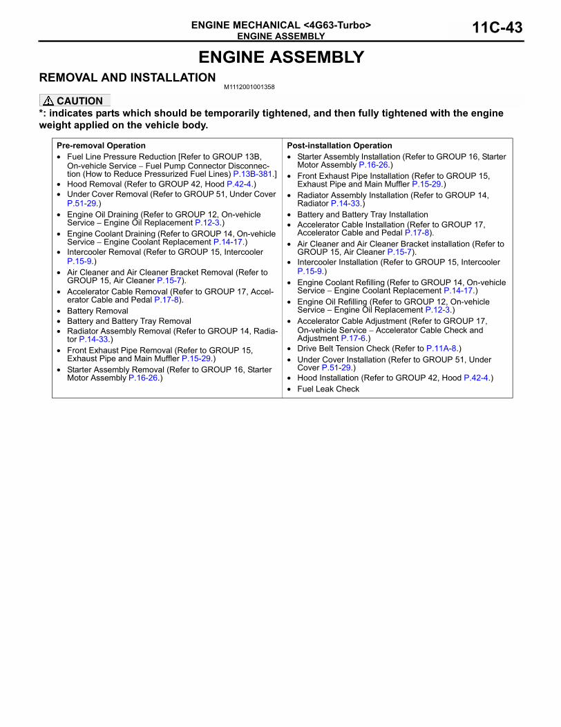
CAUTION*: indicates parts which should be temporarily tightened, and then fully tightened with the engine weight applied on the vehicle body.
Pre-removal Operation• Fuel Line Pressure Reduction [Refer to GROUP 13B,
On-vehicle Service − Fuel Pump Connector Disconnec-tion (How to Reduce Pressurized Fuel Lines) P.13B-381.]
• Hood Removal (Refer to GROUP 42, Hood P.42-4.)• Under Cover Removal (Refer to GROUP 51, Under Cover
P.51-29.)• Engine Oil Draining (Refer to GROUP 12, On-vehicle
Service − Engine Oil Replacement P.12-3.)• Engine Coolant Draining (Refer to GROUP 14, On-vehicle
Service − Engine Coolant Replacement P.14-17.)• Intercooler Removal (Refer to GROUP 15, Intercooler
P.15-9.)• Air Cleaner and Air Cleaner Bracket Removal (Refer to
GROUP 15, Air Cleaner P.15-7).• Accelerator Cable Removal (Refer to GROUP 17, Accel-
erator Cable and Pedal P.17-8).• Battery Removal• Battery and Battery Tray Removal• Radiator Assembly Removal (Refer to GROUP 14, Radia-
tor P.14-33.)• Front Exhaust Pipe Removal (Refer to GROUP 15,
Exhaust Pipe and Main Muffler P.15-29.)• Starter Assembly Removal (Refer to GROUP 16, Starter
Motor Assembly P.16-26.)
Post-installation Operation• Starter Assembly Installation (Refer to GROUP 16, Starter
Motor Assembly P.16-26.)• Front Exhaust Pipe Installation (Refer to GROUP 15,
Exhaust Pipe and Main Muffler P.15-29.)• Radiator Assembly Installation (Refer to GROUP 14,
Radiator P.14-33.)• Battery and Battery Tray Installation• Accelerator Cable Installation (Refer to GROUP 17,
Accelerator Cable and Pedal P.17-8).• Air Cleaner and Air Cleaner Bracket installation (Refer to
GROUP 15, Air Cleaner P.15-7).• Intercooler Installation (Refer to GROUP 15, Intercooler
P.15-9.)• Engine Coolant Refilling (Refer to GROUP 14, On-vehicle
Service − Engine Coolant Replacement P.14-17.)• Engine Oil Refilling (Refer to GROUP 12, On-vehicle
Service − Engine Oil Replacement P.12-3.)• Accelerator Cable Adjustment (Refer to GROUP 17,
On-vehicle Service − Accelerator Cable Check and Adjustment P.17-6.)
• Drive Belt Tension Check (Refer to P.11A-8.)• Under Cover Installation (Refer to GROUP 51, Under
Cover P.51-29.)• Hood Installation (Refer to GROUP 42, Hood P.42-4.)• Fuel Leak Check

ENGINE ASSEMBLYENGINE MECHANICAL <4G63-Turbo>11C-44
AC401183
3
45.0 ± 1.0 N·m 9.0 ± 2.0 N·m
9.0 ± 2.0 N·m
AB
5.0 ± 1.0 N·m
9.0 ± 2.0 N·m 2
9.0 ± 2.0 N·m1
N 5 N5
6
12 ± 2 N·m48 ± 7 N·m
N 5
48 ± 7 N·m
Removal steps1. Control wiring harness connection2. Earth cable connection3. Battery wiring harness connection
<<A>> 4. Drive belt
5. Engine oil cooler tube gaskets6. Engine oil cooler hose and bracket
assembly
Removal steps (Continued)
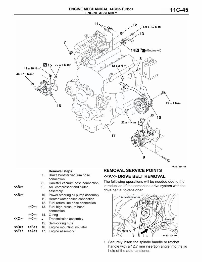
ENGINE ASSEMBLYENGINE MECHANICAL <4G63-Turbo> 11C-45
REMOVAL SERVICE POINTS<<A>> DRIVE BELT REMOVALThe following operations will be needed due to the introduction of the serpentine drive system with the drive belt auto-tensioner.
1. Securely insert the spindle handle or ratchet handle with a 12.7 mm insertion angle into the jig hole of the auto-tensioner.
AC401184
5.0 ± 1.0 N·m
44 ± 10 N·m*
70 ± 4 N·m*15
N (Engine oil)14
13
1211
10
9
8
7
17
N
22 ± 4 N·m
22 ± 4 N·m
AB
12 ± 2 N·m44 ± 10 N·m*
16
Removal steps7. Brake booster vacuum hose
connection8. Canister vacuum hose connection
<<B>> 9. A/C compressor and clutch assembly
<<B>> 10. Power steering oil pump assembly11. Heater water hoses connection12. Fuel return line hose connection
>>D<< 13. Fuel high-pressure hose connection
>>D<< 14. O-ring<<C>> >>C<< • Transmission assembly
15. Self-locking nuts<<D>> >>B<< 16. Engine mounting insulator<<E>> >>A<< 17. Engine assembly
AC301703
AC301704AB
Hole A
Auto-tensioner
Hole B

ENGINE ASSEMBLYENGINE MECHANICAL <4G63-Turbo>11C-46
2. Rotate the auto-tensioner anti-clockwise and align hole A with hole B.CAUTION
To reuse the drive belt, draw an arrow indicating the rotating direction (clockwise) on the back of the belt using chalk, etc.
3. Insert an L-shaped hexagon wrench, etc. into the hole to fix and then remove the drive belt.
<<B>> A/C COMPRESSOR AND CLUTCH ASSEMBLY/POWER STEERING OIL PUMP ASSEMBLY REMOVALWith the hose installed, remove the A/C compressor and clutch assembly, and power steering oil pump assembly from the bracket.NOTE: Secure the removed A/C compressor and clutch assembly, and power steering oil pump assembly with cord or rope at a position where they will not interfere with the removal of the engine assembly.
<<C>> TRANSMISSION ASSEMBLY REMOVAL
1. Pre-tighten the 2 bolts on the car to assemble the radiator support upper insulator to set the special tools engine hanger MB991895 or engine hanger MB991928.
2. Remove the transmission assembly (Refer to GROUP 22A, Transmission Assembly P.22A-13).
<<D>> ENGINE MOUNTING INSULATOR REMOVAL1. Support the engine with a garage jack.2. Remove the following special tool.
(1) <Special tool engine hanger (MB991895) is used>
Remove special tool MB991895.
(2) <Special tool engine hanger (MB991928) is used>
Remove special tool MB991928.
3. Hold the engine assembly with a chain block, etc.4. Place a garage jack against the engine oil pan
with a piece of wood in between so that the weight of the engine assembly is no longer being applied to the engine mounting insulator.
5. Loosen the engine mounting insulator mounting nuts and bolt, and remove the engine mounting insulator.
AC301705AB
L-shapedhexagonwrench
Auto-tensioner
AC300950AB
AC107631AB
MB991527
MB991454
MB991895
AC211405AB
MB991527
MB991454
MB991928
AC107632 AB
MB991527
MB991454

ENGINE ASSEMBLYENGINE MECHANICAL <4G63-Turbo> 11C-47
<<E>> ENGINE ASSEMBLY REMOVALAfter checking that all cables, hoses and wiring har-ness connectors and so on are disconnected from the engine, lift the chain block slowly to remove the engine assembly upward from the engine compart-ment.
INSTALLATION SERVICE POINTS>>A<< ENGINE ASSEMBLY INSTALLA-TION
Install the engine assembly, being careful not to pinch the cables, hoses or wiring harness connec-tors.
>>B<< ENGINE MOUNTING INSULATOR INSTALLATION1. Place a garage jack against the engine oil pan
with a piece of wood in between, and install the engine mounting insulator while adjusting the position of the engine.
2. Support the engine assembly with a garage jack.3. Remove the chain block.4. Use the following special tool as during removal to
support the engine.
(1) <Special tool engine hanger (MB991895) is used>
Set special tool MB991895. (Refer to GROUP 22A, Transmission Assembly P.22A-13).
(2) <Special tool engine hanger (MB991928) is used>
Set special tool MB991928 (Refer to GROUP 22A, Transmission Assembly P.22A-13).
>>C<< TRANSMISSION ASSEMBLY INSTALLATION1. Install the transmission assembly (Refer to
GROUP 22A, Transmission Assembly P.22A-13).
2. Remove from the car the 2 bolts, to assemble the radiator support upper insulator.
AC107632 AB
MB991527
MB991454
AC107631AB
MB991527
MB991454
MB991895
AC211405AB
MB991527
MB991454
MB991928
AC300950AB

ENGINE ASSEMBLYENGINE MECHANICAL <4G63-Turbo>11C-48
>>D<< O-RING/FUEL HIGH-PRESSURE HOSE INSTALLATION
CAUTIONDo not let any engine oil get into the delivery pipe.1. Apply a small amount of new engine oil to the
O-ring.2. Turning the fuel high-pressure hose to the right
and left, install it to the delivery pipe, while being careful not to damage the O-ring. After installing, check that the hose turns smoothly.
3. If the hose does not turn smoothly, the O-ring is probably being clamped. Disconnect the fuel high-pressure hose and check the O-ring for damage. After this, re-insert it to the delivery pipe and check that the hose turns smoothly.
4. Tighten the fuel high-pressure hose mounting bolts to the specified torque.
Tightening torque: 5.0 ± 1.0 N⋅m