the c in fmc - cdn.ttgtmedia.comcdn.ttgtmedia.com/.../fixed_1_mobile_convergence... · the c in fmc...
TRANSCRIPT
MH Technical title / Fixed Mobile Convergence / Shneyderman / 8606-2 /Chapter 5
Chapter
5The C in FMC
Thus they confronted: water and stone, prose and poetry, ice and flame differ less from each other.1
—Alexander Sergeevich Pushkin, Evgeni Onegin
The last step in our journey into FMC, after the review of its relevant fixed and mobile aspects in Chapters 3 and 4, respectively, is to provide a consolidated view on how fixed and mobile networks come together in the delivery of converged
telecommunication services. This will include discussing the background of modern techniques enabling convergence and their application in real-life deployments.
We start with the discussion of the FMC systems based IMS and UMA/GAN. We then consider the converged solutions based on VoIP service delivered over multi-access fixed and mobile systems, including both Wi-Fi and cellular. Finally we will take a look at femtocell technologies, which lately gained prominence as a major FMC enabler.
The section that follows opens the chapter with an overview of convergence tech-nology fundamentals.
Convergence Technology Fundamentals
The delivery of converged services implies the involvement of both the end-user device and the network in creating the converged communication experience, allowing the user, either transparently or with explicit actions (depending on each service definition), to access a service through a variety of access networks. Essentially service is always avail-able wherever there is coverage via one of the converged access technologies. Such avail-ability is achieved potentially via different levels of fixed and mobile access integration.
A converged service and applications also benefit from information stored in user profiles and some context information such as user location and real-time availability
133
1 Они сошлись: вода и камень, Стихи и проза, лед и пламень. Не столь различны меж собой.
ch05.indd 133 12/12/07 4:31:31 PM

134 Chapter 5
MH Technical title / Fixed Mobile Convergence / Shneyderman / 8606-2 /Chapter 5
status (also known as presence—see Chapter 6). The combination of user context and user profile allows an operator (and the subscriber, if the user profile is user-customizable) to define a number of converged access policies and reachability profiles, depending on location, time of day, user preferences, and the access network type the user is camped on at a given moment.
Various technologies have been proposed in the industry to enable fixed-mobile con-vergence. Most of them are more oriented to converged services delivered by a mobile network operator (like UMA/GAN), since the level of integration there is higher and implies the use of the existing mobile network standard interfaces such as the GSM A interface and the GPRS Gb interface.
Other technologies—such as the IMS-based approaches—are more neutral to the type of operator delivering the service and can be adopted more widely across the in-dustry, as the level of integration with the underlying fixed or mobile networks is looser, because the converged service experience is realized at the Service/Application layer.
Let’s then delve into the analysis of service availability and details of specific levels of integration and their impact on the user experience (which we are going to explore in detail in the following chapter).
Levels of Integration
The success of a given FMC solution is a matter not only of making sure subscribers can access a service via particular access methods, but also of making network selec-tion and switchover seamless and unnoticeable unless explicit notification is desired as part of the service definition (“you are now in the home zone where calling is free”). The seamless mobile experience users are accustomed to in a cellular environment should therefore be preserved and replicated as closely as possible in other access networks and application domains.
Of course, this broad requirement presents significant technical and usability chal-lenges. Solutions to address them have been found and keep being identified as the industry successfully deals with the intricacies of delivering the converged network service experience.
From the integration point of view, convergence solutions can be broadly classified as “application-level” solutions (where an application on the terminal and application serv-ers in the network cooperate in delivering the converged service experience), or “verti-cally integrated,” that is, based on the user terminal cooperating with the network below the Application layer. In this model applications are not really required to support the delivery of the converged service experience, as the underlying infrastructure creates the appearance of a seamless connectivity via heterogeneous access networks. The former case is supported by technologies such as Voice Call Continuity (VCC), and the latter case is supported by UMA/GAN and femtocell approaches described later in the chapter.
Vertically integrated approaches can be then seen as ways to interface to the existing core infrastructure without the need for fundamental changes in network operation. This leaves the service delivery paradigm virtually unchanged and keeps it independent of the method of access. In other words, the investment necessary to bring vertically in-tegrated solutions to life is concentrated in the access, terminals, and business models.
ch05.indd 134 12/12/07 4:31:31 PM
The C in FMC 135
MH Technical title / Fixed Mobile Convergence / Shneyderman / 8606-2 /Chapter 5
The application-level solutions, conversely, tend to leave the access network invari-ant to the deployment of converged services (no need of special access controllers or devices other than classic wireless routers with DSL or LAN interfaces in the premises where service is accessed through noncellular transport). These solutions, however, require terminals to have special software clients, and the core network to cooperate with these devices at the application level. The core network also must make sure that service delivery is uniform and service settings remain synchronized in the converged networks’ domains.
VoIP-Based Convergence
The transition of traditional PSTN telephony to VoIP is contagious. The rise of inter-est in Voice over Wi-Fi is the latest evidence of this trend. The cellular industry is not far behind with a slew of new radio interfaces focused on the support of multimedia services such as CDMA EV-DO revA (also known as DOrA, to be used by the operators relying on 3GPP2 standards) and HSPA (to be adopted by 3GPP-bound operators) be-ing rolled out around the world. The practical deployments of the VoIP-based solutions in cellular environments, however, have to deal with many issues, both technical and nontechnical, mostly absent in the fixed environment.
For one thing, cellular operators tend to maintain more stringent control over the access to the radio resources necessary to provide cellular services than wireline opera-tors do over local loop or cable. The reason for that is quite simple, in that expensive licensed spectrum is shared among subscribers, and operators seek to maximize the return on their investment.
Second, the currently deployed cellular networks cannot fully support the VoIP ser-vice. For instance, they are lacking mechanisms to support guaranteed QoS for packet data services. On the other hand, although the new technologies capable of supporting VoIP in cellular environments2 are already available, they are still months if not years away from widespread deployment, thus making cellular VoIP service support very lim-ited, and only available in some vertical segments of the market, in the short term.
Finally, cellular VoIP requires new devices or new clients in the existing devices, which in turn calls for significant investment and long-term effort to be put in place by device manufacturers and their suppliers or independent software vendors.
For these reasons it can be argued that VoIP in a wireless environment, at least in the coming years, will be less likely to experience the level of freedom and growth we are witnessing today in wireline broadband. Despite that, the long-term future of cellular wireless VoIP is bright. We are convinced that competitive forces and econo-mies of scale will eventually lead to parity between VoIP services over fixed and wire-less networks and even the potential of uniform treatment of non-operator-controlled VoIP applications.3
2 DOrA technology, for example, supports QoS standards necessary for differentiated VoIP traffic treatment.
3 Imagine a commercial cellular VoIP offering from Skype.
ch05.indd 135 12/12/07 4:31:32 PM
136 Chapter 5
MH Technical title / Fixed Mobile Convergence / Shneyderman / 8606-2 /Chapter 5
Unlike non-operator-controlled VoIP, the operator-controlled VoIP services4 require the deployment of specific telephony applications and the necessary interworking in-frastructure needed to interface to the legacy circuit-switched voice subscribers both on cellular networks and in the PSTN. It is also necessary to ensure voice call continuity in areas with mixed VoIP and circuit coverage, or in other words, seamless handover of active calls between VoIP and legacy circuit TDM.
However, once IMS-based VoIP is uniformly deployed in the converged cellular and fixed networks, the resulting access independence of the converged core will ensure the right user experience. The mechanisms to ensure service continuity and active call handover between cellular and noncellular can at that point in time be implemented at the IP layer, using mature technologies such as Mobile IP (see RFC 3220 [22]) or other IP mobility support protocols.
Until that happens, the industry will have to deal with a difficult task of building FMC solutions combining dissimilar packet and circuit voice services implemented over heterogeneous access networks. The rest of this section is devoted to the discussion of such solutions.
The Dual Nature of Dual Mode
The contemporary voice FMC solutions supporting operation over Wi-Fi and cellular access networks are most often called dual-mode solutions. Such dual-mode FMC solutions can be based on a variety of technologies. The most prominent are the two standards-based approaches: One is built around IMS; the other is based on UMA/GAN, defined for the GSM cellular systems. Both approaches effectively converge cir-cuit cellular voice and VoIP over Wi-Fi/broadband by “hiding” the Wi-Fi access media and signaling from the cellular core network.
However, that’s where the similarity ends. While UMA/GAN attempts to tackle the problem of delivering converged services from the lower layers of the protocol stack, the IMS enables convergence at the higher layers. The IMS VoIP approach places the han-dling of the voice call in the IMS core network and allows for a significant part of the voice traffic to be offloaded from the cellular network core. Unlike IMS, the UMA/GAN standard enables the support of a Wi-Fi infrastructure by making it look like a set of GSM base station controllers, thus making Wi-Fi appear as just another 3GPP radio interface and requiring all traffic to traverse the 3GPP core network.
To better understand these aspects and more, in the following sections we discuss the fundamentals of both IMS and UMA/GAN FMC methods.
IMS and MMD Fundamentals
The IP Multimedia Subsystem (IMS) and the Multimedia Domain (MMD) are the 3GPP and 3GPP2 versions of the same thing, that is, an IP- and SIP-based system
4 IMS is on target to become the de facto platform for delivery of cellular VoIP services (along with a variety of other multimedia services).
ch05.indd 136 12/12/07 4:31:32 PM

The C in FMC 137
MH Technical title / Fixed Mobile Convergence / Shneyderman / 8606-2 /Chapter 5
defined to handle multimedia signaling in the wireless domain. This system supports communications among SIP user agents accessing an IP network and various SIP servers within the network, using the 3GPP and 3GPP2 systems’ packet data net-works’ access services.
Standardization There are only minor differences between the 3GPP and 3GPP2 ver-sions of IMS, and from almost every practical angle these versions can be considered similar, if not identical. There is in fact a cooperation agreement in place between 3GPP and 3GPP2 organizations, whereby 3GPP2 adopts the 3GPP IMS specifications, only with minor modifications to suit the unique 3GPP2 market needs.
Over time, the intrinsic access-independence of IMS (albeit IMS still has some access-specific details surfacing mostly at the Protocol layer) has prompted its adoption as a core enabler for other wireless access technologies such as WiMax and even for wireline networks.
It is important to point out that the proliferation and applicability of IMS to mul-tiple access technologies has been its goal from the beginning. IMS was originally de-fined by 3GPP around the year 2000, following intense activity by the 3G.IP industry focus group, initially driven by AT&T, at that time interested in both wireless and cable networks. Therefore, the driver behind the standardization effort was to define a solution that, while delivering an IP-based platform for wireless multimedia services, as required by the wireless arm of AT&T, could also be used for other access technolo-gies, especially cable.
It is no surprise, then, that as of late the wireline operators’ community is increas-ingly considering IMS as the platform for their VoIP services. For instance, the BT 21st Century network, the first major-scale IP transformation project in the world carried out by an incumbent wireline operator, will migrate over time to IMS after an initial de-ployment based on an architecture closer to the server model (introduced in Chapter 3). Cable operators are also embracing IMS (as it was meant to be from day one, now we can say!), through their CableLabs industry forum.
But why are all these different branches of the telecom industry embracing the IMS and not its alternatives? There are two main reasons:
■ The IMS is not only a standardized architecture for delivery of VoIP service, but also a general platform supporting all kinds of IP-based multimedia applications (text, images, instant messaging, conferencing, presence, and video telephony).
■ The IMS core network can be shared by multiple access technologies, so it can be deployed by operators intending to pursue the convergence path, seeking to enter triple or quadruple plays, or just looking for more flexibility in the “last mile.”
In the following sections we provide a technical overview of the IMS architecture, point out its differences from MMD, and discuss the IMS-based FMC solutions.
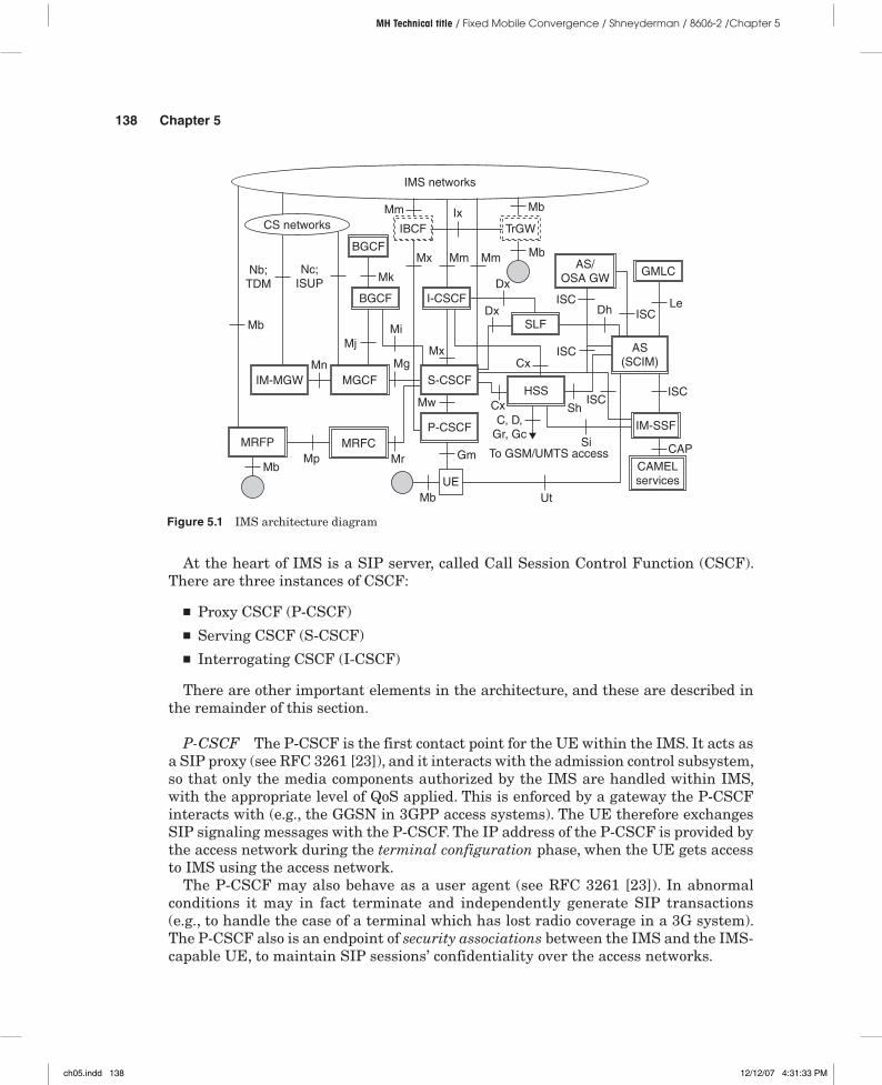
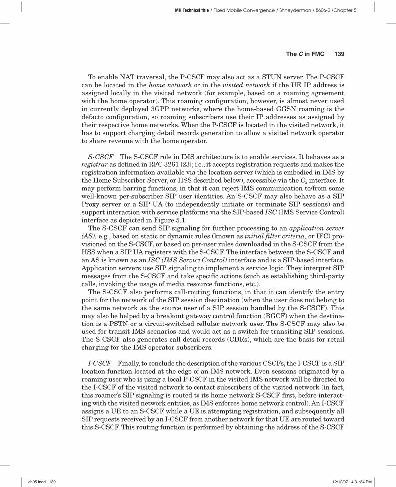
Architecture and Components As evident from Figure 5.1, the IMS architecture is quite complex.
ch05.indd 137 12/12/07 4:31:32 PM
138 Chapter 5
MH Technical title / Fixed Mobile Convergence / Shneyderman / 8606-2 /Chapter 5
At the heart of IMS is a SIP server, called Call Session Control Function (CSCF). There are three instances of CSCF:
■ Proxy CSCF (P-CSCF)■ Serving CSCF (S-CSCF)■ Interrogating CSCF (I-CSCF)
There are other important elements in the architecture, and these are described in the remainder of this section.
P-CSCF The P-CSCF is the first contact point for the UE within the IMS. It acts as a SIP proxy (see RFC 3261 [23]), and it interacts with the admission control subsystem, so that only the media components authorized by the IMS are handled within IMS, with the appropriate level of QoS applied. This is enforced by a gateway the P-CSCF interacts with (e.g., the GGSN in 3GPP access systems). The UE therefore exchanges SIP signaling messages with the P-CSCF. The IP address of the P-CSCF is provided by the access network during the terminal configuration phase, when the UE gets access to IMS using the access network.
The P-CSCF may also behave as a user agent (see RFC 3261 [23]). In abnormal conditions it may in fact terminate and independently generate SIP transactions (e.g., to handle the case of a terminal which has lost radio coverage in a 3G system). The P-CSCF also is an endpoint of security associations between the IMS and the IMS-capable UE, to maintain SIP sessions’ confidentiality over the access networks.
Figure 5.1 IMS architecture diagram
IMS networks
Mm Ix Mb
Mm MmMx
MkNc;
ISUP
Mb
Nb;TDM
Mb
Mn
MjMi
Dx
DxISC
Dh ISCLe
ISCCx
MxMg
Mw Cx ShISC
ISC
SiTo GSM/UMTS access
Ut
Gm
Mb
MrCAP
C, D,Gr, Gc
MpMb
BGCF
IBCF TrGW
AS/OSA GW
GMLC
AS(SCIM)
IM-SSF
CAMELservices
P-CSCFMRFCMRFP
IM-MGW MGCF S-CSCFHSS
SLF
I-CSCFBGCF
UE
CS networks
ch05.indd 138 12/12/07 4:31:33 PM
The C in FMC 139
MH Technical title / Fixed Mobile Convergence / Shneyderman / 8606-2 /Chapter 5
To enable NAT traversal, the P-CSCF may also act as a STUN server. The P-CSCF can be located in the home network or in the visited network if the UE IP address is assigned locally in the visited network (for example, based on a roaming agreement with the home operator). This roaming configuration, however, is almost never used in currently deployed 3GPP networks, where the home-based GGSN roaming is the defacto configuration, so roaming subscribers use their IP addresses as assigned by their respective home networks. When the P-CSCF is located in the visited network, it has to support charging detail records generation to allow a visited network operator to share revenue with the home operator.
S-CSCF The S-CSCF role in IMS architecture is to enable services. It behaves as a registrar as defined in RFC 3261 [23]; i.e., it accepts registration requests and makes the registration information available via the location server (which is embodied in IMS by the Home Subscriber Server, or HSS described below), accessible via the Cx interface. It may perform barring functions, in that it can reject IMS communication to/from some well-known per-subscriber SIP user identities. An S-CSCF may also behave as a SIP Proxy server or a SIP UA (to independently initiate or terminate SIP sessions) and support interaction with service platforms via the SIP-based ISC (IMS Service Control) interface as depicted in Figure 5.1.
The S-CSCF can send SIP signaling for further processing to an application server (AS), e.g., based on static or dynamic rules (known as initial filter criteria, or IFC) pro-visioned on the S-CSCF, or based on per-user rules downloaded in the S-CSCF from the HSS when a SIP UA registers with the S-CSCF. The interface between the S-CSCF and an AS is known as an ISC (IMS Service Control) interface and is a SIP-based interface. Application servers use SIP signaling to implement a service logic. They interpret SIP messages from the S-CSCF and take specific actions (such as establishing third-party calls, invoking the usage of media resource functions, etc.).
The S-CSCF also performs call-routing functions, in that it can identify the entry point for the network of the SIP session destination (when the user does not belong to the same network as the source user of a SIP session handled by the S-CSCF). This may also be helped by a breakout gateway control function (BGCF) when the destina-tion is a PSTN or a circuit-switched cellular network user. The S-CSCF may also be used for transit IMS scenarios and would act as a switch for transiting SIP sessions. The S-CSCF also generates call detail records (CDRs), which are the basis for retail charging for the IMS operator subscribers.
I-CSCF Finally, to conclude the description of the various CSCFs, the I-CSCF is a SIP location function located at the edge of an IMS network. Even sessions originated by a roaming user who is using a local P-CSCF in the visited IMS network will be directed to the I-CSCF of the visited network to contact subscribers of the visited network (in fact, this roamer’s SIP signaling is routed to its home network S-CSCF first, before interact-ing with the visited network entities, as IMS enforces home network control). An I-CSCF assigns a UE to an S-CSCF while a UE is attempting registration, and subsequently all SIP requests received by an I-CSCF from another network for that UE are routed toward this S-CSCF. This routing function is performed by obtaining the address of the S-CSCF
ch05.indd 139 12/12/07 4:31:34 PM
140 Chapter 5
MH Technical title / Fixed Mobile Convergence / Shneyderman / 8606-2 /Chapter 5
from the HSS via the Cx interface. The I-CSCF also generates CDRs, which are useful for billing reconciliation and peering charges settlement between operators.
IBCF To capture the role of session border controllers (SBCs), which are used (be-tween operators or between the IMS operator and its subscribers), the IMS standards identify an additional function named the Interconnection Border Control Function (IBCF). This function is collocated with (or represents) the entry point to the IMS net-work. The interfaces Mx toward the CSCFs and the BGCF are represented in the IMS architecture to underscore the logical separation from the CSCF. In physical imple-mentations, however, both the BGCF and the CSCF are often supported by the same physical platform as the IBCF.
The IBCF provides functions necessary to perform interconnection between two operator domains, such as two IMS operators or an IMS operator and an ISP using SIP signaling to support VoIP applications. For instance, it can enable communication between IPv6 and IPv4 SIP endpoints, hide network topology by performing NAT functions such as IP address and (or) port translation, or act as a SIP firewall and generate CDRs related to peering between operators.
An IBCF interfaces to a transition gateway (TrGW) via the Ix interface. The TrGW handles media and is controlled by the IBCF. The TrGW also provides functions like net-work address/port translation and IPv4/IPv6 protocol translation. It may also implement and enforce firewalling rules (e.g., opening and closing pinholes on the media path, based on IBCF decisions). To date, since Ix is not yet specified down to the protocol level in the standards, all physical implementations of IBCF and TrGW are supported on the same physical platform, just as with BGCF and CSCF.
AS, SCIM, and IM-SSF An application server is a SIP B2BUA that can process incoming SIP messages and, based on the information in a SIP message, generate new SIP messages and take actions based on the service logic it implements. It can also of-fer open interfaces toward third-party applications in the form of an API (application programming interface). In this sense it can act as a broker toward other servers. The importance of the AS function in FMC will be clarified in the section “VCC.”
An S-CSCF may interact via the ISC interface with multiple application servers directly, or via an application server acting as a broker. An application server acting as a broker is considered, in standards parlance, to implement the Service Capability Interaction Manager (SCIM) feature. An AS implementing the SCIM feature can interact with a variety of application servers over ISC interfaces to deliver the desired service.
In the same way as an S-CSCF, a SCIM may interact with SIP application serv-ers, Open Service Architecture (OSA) gateways, or IM-SSFs (IMS Service Switching Functions). The IM-SSF offers an ISC interface toward an S-CSCF or a SCIM, and a CAMEL Application Part (CAP, an SS7–based Intelligent Network signaling) in-terface toward the CAMEL Service Environment.5 The IM-SSF downloads from the
5 CAMEL (standing for Customized Applications for Mobile Network Enhanced Logic) services are Intelligent Network services in a 3GPP mobile environment. Their equivalents in 3GPP2-based systems are governed by WIN2 standards.
ch05.indd 140 12/12/07 4:31:34 PM
The C in FMC 141
MH Technical title / Fixed Mobile Convergence / Shneyderman / 8606-2 /Chapter 5
HSS the CAMEL triggers for a specific user and then arms them via the Si interface. Similarly, an AS can retrieve application data for a subscriber from the HSS via the Sh interface and access user location information available in the Gateway Mobile Location Center (GMLC) via the Le interface.
MRFC and MRFP While conferencing capabilities can be implemented in IMS by means of a dedicated AS, with the terminal setting up the conference via the Ut interface with the application server, there is a function in the IMS that is specifi-cally defined for that very purpose, the Multimedia Resources Function Controller (MRFC) combined with the Multimedia Resources Function Processor (MRFP). The MRFC and MRFP can also be used to deliver tones and announcements and to gen-erate multimedia content necessary for a specific IMS session. Unfortunately, the specification of the Mp interface between the MRFP and MRFC has been developing quite slowly, and to date it is still a bit undefined, so in most cases the market has gone in the direction of proprietary solutions based on application servers hosting media-processing capabilities.
MGW and IM-MGW In IMS, the interworking with CS networks, whether toward classic GSM and CDMA networks and the PSTN based on TDM and ISUP, or a BICC-based bearer-independent, circuit-switched core network (based on the Rel-4 specifica-tions of 3GPP, namely 3GPP TS 23.205 [184]), is made possible by the Media Gateway Control Function (MGCF) and the IMS Media Gateway (IM-MGW). Many sources also refer to MGCF as a softswitch, as it performs functions equivalent to that of a class 5 TDM switch in the PSTN.6
Media gateways are controlled by MGCF and perform transcoding between different speech formats used in the CS and IMS networks. They may be put in the path also when different IMS networks adopt different voice encoding formats (e.g., a 3GPP2 net-work may use EVRC [65] encoding for speech while a 3GPP network may use AMR [63] or WB-AMR [64]).
Since IMS-based FMC scenarios in the immediate future involve interworking between CS networks and IMS-based VoIP, the media gateways play a fundamental role in FMC.
HSS and SLF The HSS—also referred to as User Profile Server Function, or UPSF, by TISPAN—is a subscriber database providing subscriber data to the IMS elements that require this information while handling calls and sessions. In addition, the HSS performs authentication and authorization functions and can act as a SIP location server.
The HSS was originally conceived as an evolution of the traditional HLR and AUC, and as a consequence, it is also capable of supporting the legacy MAP signaling interfaces toward MSCs (C and D interfaces, where D is used toward gateway MSCs), SGSN (via the Gr interface), and the GGSN (the Gc interface) in GPRS.
6 Softswitches and media gateways create their own complex field. If you are willing to probe further, you can refer to an excellent book by Frank Ohrtman, Softswitch: Architecture for VoIP (McGraw-Hill, 2002).
ch05.indd 141 12/12/07 4:31:35 PM
142 Chapter 5
MH Technical title / Fixed Mobile Convergence / Shneyderman / 8606-2 /Chapter 5
It should be noted that the Home Subscriber Server (HSS) in Figure 5.1 is also accompanied by a Subscriber Locator Function (SLF). An SLF is used in IMS deploy-ments with more than one addressable HSS. In this case, network entities that require access to HSS subscriber data need to access the SLF to identify the HSS in which a specific subscriber’s data is actually stored. The Dx interface is used to access the SLF from I and S CSCFs. The Dh interface is used to access the SLF from an AS.
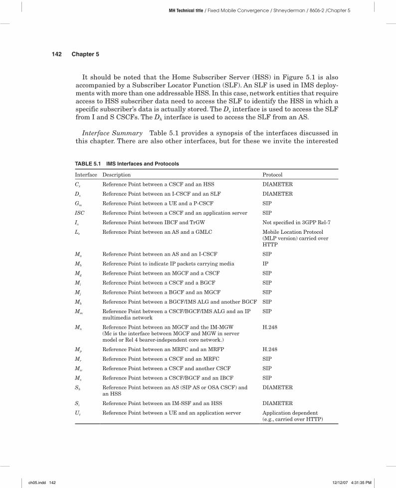
Interface Summary Table 5.1 provides a synopsis of the interfaces discussed in this chapter. There are also other interfaces, but for these we invite the interested
TABLE 5.1 IMS Interfaces and Protocols
Interface Description Protocol
Cx Reference Point between a CSCF and an HSS DIAMETER
Dx Reference Point between an I-CSCF and an SLF DIAMETER
Gm Reference Point between a UE and a P-CSCF SIP
ISC Reference Point between a CSCF and an application server SIP
Ix Reference Point between IBCF and TrGW Not specified in 3GPP Rel-7
Le Reference Point between an AS and a GMLC Mobile Location Protocol (MLP version) carried over HTTP
Ma Reference Point between an AS and an I-CSCF SIP
Mb Reference Point to indicate IP packets carrying media IP
Mg Reference Point between an MGCF and a CSCF SIP
Mi Reference Point between a CSCF and a BGCF SIP
Mj Reference Point between a BGCF and an MGCF SIP
Mk Reference Point between a BGCF/IMS ALG and another BGCF SIP
Mm Reference Point between a CSCF/BGCF/IMS ALG and an IP multimedia network
SIP
Mn Reference Point between an MGCF and the IM-MGW (Mc is the interface between MGCF and MGW in server model or Rel 4 bearer-independent core network.)
H.248
Mp Reference Point between an MRFC and an MRFP H.248
Mr Reference Point between a CSCF and an MRFC SIP
Mw Reference Point between a CSCF and another CSCF SIP
Mx Reference Point between a CSCF/BGCF and an IBCF SIP
Sh Reference Point between an AS (SIP AS or OSA CSCF) and an HSS
DIAMETER
Si Reference Point between an IM-SSF and an HSS DIAMETER
Ut Reference Point between a UE and an application server Application dependent (e.g., carried over HTTP)
ch05.indd 142 12/12/07 4:31:35 PM
The C in FMC 143
MH Technical title / Fixed Mobile Convergence / Shneyderman / 8606-2 /Chapter 5
readers to probe further in the IMS literature, such as, but not limited to, 3GPP TS 23.228 [66], 3GPP TS 24.228 [67], and books such as [68] and [69].
Subscriber Identity Within an AS, a CSCF, an HSS, or a UE a particular user is uniquely identified by means of a user identity. A user identity can be in the format of a SIP URI–RFC 3261 [23] or a Tel URI–RFC3966 [30] defined in Chapter 3. A SIP URI has the following format:
SIP URI = sip:x@y:Portnumber Where x=Username and y=hostname¦domain
Examples of SIP URIs are
sip:[email protected]:1218 sip:[email protected] sip: sip:[email protected]
IMS supports both private and public user identities. Public identities are advertised externally to the IMS, are in the SIP URI format, and are public to other users, much in the same way as e-mail addresses and telephone numbers are public. Private user identi-ties take the format of an NAI–RFC4282 [70], i.e., “username@realm.” They are associated with the user subscription and used by the UE to register with the network. They are also used for authentication of the user and to access the HSS data for the subscriber.
The private user identity is stored in the I-SIM application (IMS – SIM), provided with the UICC (User Identity Chip Card—a smart card provided to 3GPP and some 3GPP2 operators’ customers, commonly known as SIM—Subscriber Identity Module—by most GSM networks users) given to the user as part of the IMS service subscription. Users may be contacted through a variety of public user identities that they give out to other users. These identities can be associated with the same service or with different IMS services. At least one public identity needs to be stored on the I-SIM application. The network then translates these to a single private user identity for its internal operation (e.g., charging, database access, etc.). Note that private user identities are not used in SIP messages.
Some IMS services also require the capability to interact with a group of users that is dynamically or statically defined. An example is a chat list, where a number of users can post messages to the list and receive messages from the list. This is also necessary for multimedia conferencing applications and in general for group services. For this purpose, the concept of Public Service Identity (PSI) has been defined in IMS. A PSI is in the form of a SIP URI; it could be, for instance:
Messages addressed to a PSI apply to a group of users or a particular service hosted on a SIP AS. The IMS can support addressing in SIP messages using Public User Identities or Public Service Identities.
Access-Specific Procedures While IMS is generally defined as an access-independent architecture, it was necessary to identify some access-specific procedures needed to cover
ch05.indd 143 12/12/07 4:31:36 PM
144 Chapter 5
MH Technical title / Fixed Mobile Convergence / Shneyderman / 8606-2 /Chapter 5
access-specific security mechanisms, access-specific information, and P-CSCF discovery. The 3GPP IMS specifications also define the use of a P-Access-Network-Info header, part of the Private Header (P-Header) Extensions to the SIP for 3GPP (RFC 3455 [71]).
This access network–specific information element can identify the cell ID the user is in, the specific technology being used, and other access-specific parameters. The infor-mation about the type of access technology can be utilized by the network to customize service operation to the capabilities of the access network. The information to be in-serted by a UE in the P-Access-Network-Info is specified in 3GPP TS 24.229 [72]. The syntax of this header, as described in 3GPP TS 24.229, is the following:
access-type = "IEEE-802.11" / "IEEE-802.11a" / "IEEE-802.11b" / "IEEE-802.11g" / "3GPP-GERAN" / "3GPP-UTRAN-FDD" / "3GPP-UTRAN-TDD" / "ADSL" / "ADSL2" / "ADSL2+" / "RADSL" / "SDSL" / "HDSL" / "HDSL2" / "G.SHDSL" / "VDSL" / "IDSL" / "3GPP2-1X" / "3GPP2-1X-HRPD" / "DOCSIS" / token access-info = cgi-3gpp / utran-cell-id-3gpp / dsl-location / i-wlan-node-id / ci-3gpp2 / extension-access-info extension-access-info = gen-value cgi-3gpp = "cgi-3gpp" EQUAL (token / quoted-string) utran-cell-id-3gpp = "utran-cell-id-3gpp" EQUAL (token / quoted-string) i-wlan-node-id = "i-wlan-node-id" EQUAL (token / quoted-string) dsl-location = "dsl-location" EQUAL (token / quoted-string) ci-3gpp2 = "ci-3gpp2" EQUAL (token / quoted-string)
This header specifies the access technology type using the access-type parameter, and some access-specific information using the access-info parameter. The parameters can take any of the alternate values described already. The “gen-value” parameter can be an arbitrary defined value, which inevitably can only be used intradomain or within a federation of operators who agree on its meaning.
IMS vs. MMD As we discussed at the beginning of this section, the IMS has been initially defined within wireless standards bodies defining cellular systems. Since today there are two main standards bodies for cellular systems specifications definition, 3GPP and 3GPP2, there are consequentially two flavors of IMS, which are almost identical with the exception of specific deployment-related aspects. These differences, however, do not affect interoperability between the 3GPP and 3GPP2 versions of IMS.
Of course, one such difference is in the name: IMS in 3GPP and MMD in 3GPP2; but certainly this has nothing technical to it! Other differences are more substantial. For instance, 3GPP IMS mandates IPsec to be used between the UE and P-CSCF to secure IMS signaling, while 3GPP2 allows for P-CSCF and UE to negotiate other se-curity mechanisms using RFC 3329 [73] (an IETF recommendation on how to set up security mechanisms for SIP). Also, 3GPP IMS terminals have UICCs, whereas MMD does not require a smart card, as 3GPP2 UEs may not be equipped with a Removable User Identity Module (R-UIM). So, as a consequence, in MMD, subscriber identity information can be stored in the terminal itself or in the R-UIM; albeit 3GPP2 sup-ports UICC + I-SIM for operators that choose that method.
In 3GPP, it is also possible for a UE to access the IMS without an I-SIM. For this pur-pose, the 3GPP IMS creates temporary Public/Private IDs to support terminals without
ch05.indd 144 12/12/07 4:31:36 PM
The C in FMC 145
MH Technical title / Fixed Mobile Convergence / Shneyderman / 8606-2 /Chapter 5
I-SIM applications. This was not a feature of MMD Rev 0 (the first release of MMD), but it is now supported in MMD Rev A. However, the way MMD generates these identities is different from 3GPP IMS because 3GPP and 3GPP2 accesses use very different ways to identify a subscriber. 3GPP systems use ITU-T recommendation E.212 [74]–based International Mobile Subscriber Identity (IMSI), while 3GPP2 systems use a Mobile Identity Number (MIN)–based Mobile Subscriber Identifier (MSID). It should be noted that 3GPP2 specifications support IMSI-based operations based on IS-751 [75], but the adoption of this has been quite limited.
The HSS in 3GPP also offers legacy interfaces, as it behaves as a classic HLR toward the CS and PS domains of the 3GPP access system. In 3GPP2, however, the HSS acts as a AAA server and subscriber database only for IMS and the 3GPP2 PS domain, thus representing a totally new function in the network, dedicated to PS services.
The UE in 3GPP2 also supports some 3GPP2-specific parameters in the SIP P-Access Network-Info header information provided in registration messages to the P-CSCF. There are also differences in the P-CSCF discovery procedures, in that 3GPP2 sup-ports static configuration and DHCP, while 3GPP can use the 3GPP access signaling to discover the P-CSCF (the P-CSCF IP address can be provided in the signaling involved in PDP context activation).
Finally, in 3GPP, the P-CSCF can be in the visited network or in the home network, while in 3GPP2, the P-CSCF can only be in the home network when Mobile IP is used, and in the visited network when Simple IP is used. So, in 3GPP2, the roaming model includes a PCC interface between the visited network and the home network to enable the enforcement of PCC for roaming users using the Simple IP service.
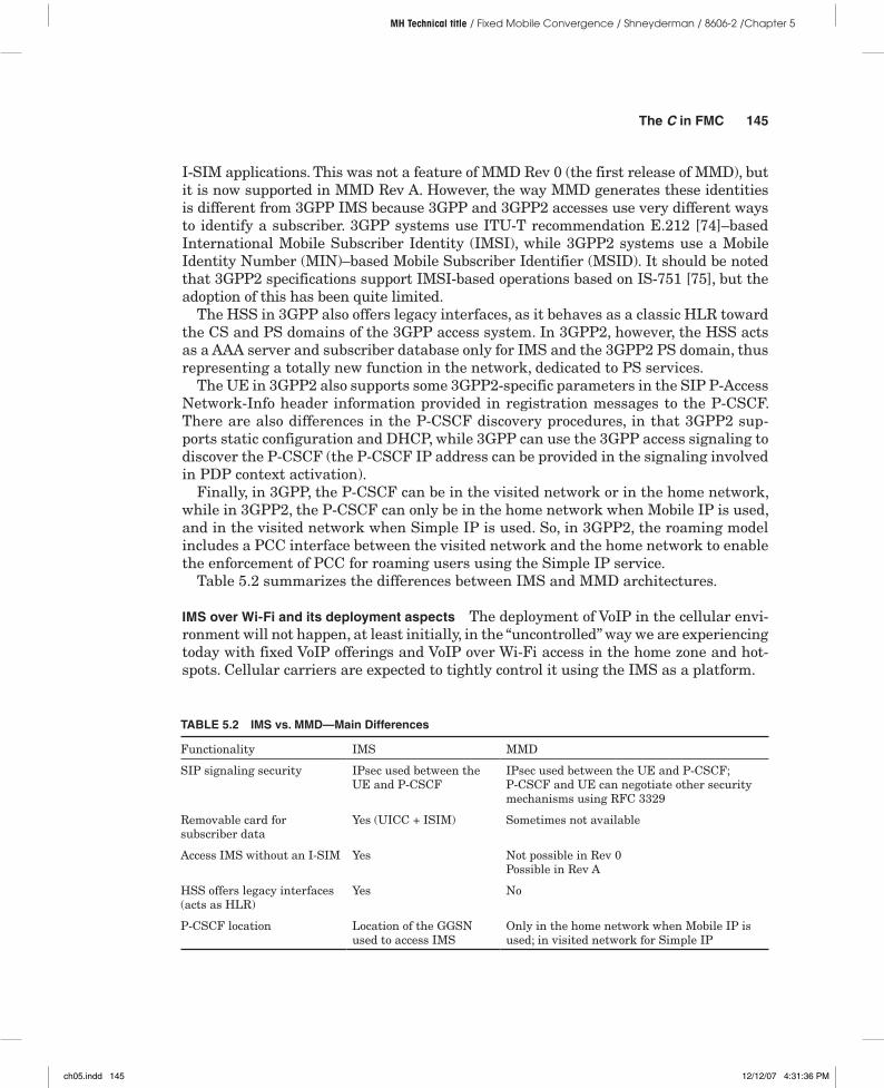
Table 5.2 summarizes the differences between IMS and MMD architectures.
IMS over Wi-Fi and its deployment aspects The deployment of VoIP in the cellular envi-ronment will not happen, at least initially, in the “uncontrolled” way we are experiencing today with fixed VoIP offerings and VoIP over Wi-Fi access in the home zone and hot-spots. Cellular carriers are expected to tightly control it using the IMS as a platform.
TABLE 5.2 IMS vs. MMD—Main Differences
Functionality IMS MMD
SIP signaling security IPsec used between the UE and P-CSCF
IPsec used between the UE and P-CSCF; P-CSCF and UE can negotiate other security mechanisms using RFC 3329
Removable card for subscriber data
Yes (UICC + ISIM) Sometimes not available
Access IMS without an I-SIM Yes Not possible in Rev 0 Possible in Rev A
HSS offers legacy interfaces (acts as HLR)
Yes No
P-CSCF location Location of the GGSN used to access IMS
Only in the home network when Mobile IP is used; in visited network for Simple IP
ch05.indd 145 12/12/07 4:31:36 PM
146 Chapter 5
MH Technical title / Fixed Mobile Convergence / Shneyderman / 8606-2 /Chapter 5
Rolling out VoIP using IMS (whether in a wireline, Wi-Fi, or cellular environment) requires the deployment of some specific telephony application servers and other elements of the interworking infrastructure needed to interface to both cellular and PSTN circuit-switched voice subscribers. This per se would not allow for a converged service experience, as the various types of access would not be blended transparently to the user of a dual mode Wi-Fi and cellular access-capable UE.
To ensure successful fixed mobile convergence while delivering voice services in a mixed cellular and Wi-Fi environment to users of dual mode UE’s, it is therefore necessary to create a mechanism to ensure continuity of voice calls across technologies. Over cellular access it may in fact be possible that IMS-based voice service is not yet supported, while it is over Wi-Fi, when Wi-Fi is used to access the IMS over, for instance, a DSL access. As an aside, this same mechanism would also be required within a cellular access technology, between areas where the network has been upgraded to support VoIP and areas where service has to fall back to circuit-switched telephony, as no upgrade has taken place.
In addition, operator-controlled VoIP support in cellular or Wi-Fi environments re-quires the operators to comply with regulatory requirements for the provision of emer-gency services over packet accesses.
Focusing on Wi-Fi access, there exist three main deployment scenarios:
■ Enterprise■ Hotspot■ Residential broadband or home zone
In an enterprise environment, the deployment of VoIP and FMC is normally not based on a commercial service unless outsourced to a third party, such as a VoIP opera-tor or integrator, which may also offer other voice and data services to the organization, and comes under the CIO jurisdiction. A potential commercial service in an enterprise environment using the Wi-Fi access could be a wireless IP Centrex, whereby the PBX service is virtually hosted in the operator’s network combined with in-house network of interconnected Wi-Fi access points.
In hotspot areas, the Wi-Fi operator could offer IMS FMC service, accomplishing two major goals. On the retail side, the offer of VoIP can provide access to voice services at a discount versus cellular access (and perhaps allow for very advantageous propositions for users frequently roaming abroad, when hotspots are operated internationally or when fed-erations of hotspot providers come together to offer VoIP services also for roaming users). On the wholesale side, the hotspot provider may offer cellular network offload services, for those subscribers using dual-mode cellular/Wi-Fi terminals. This may also take advantage of Voice Call Continuity (VCC)7 capabilities offered by the home cellular network.8
In a residential environment, VoWi-Fi is normally used as a cordless-like alterna-tive to fixed VoIP service, when a wireless DSL router or cable modem is deployed, or as part of a converged solution offered and controlled by a cellular network operator,
7 The voice call continuity feature is described later in the chapter.
8 Chapter 6 provides further discussion on business aspects of VoIP deployment and convergence.
ch05.indd 146 12/12/07 4:31:37 PM
The C in FMC 147
MH Technical title / Fixed Mobile Convergence / Shneyderman / 8606-2 /Chapter 5
like IMS-based or GAN/UMA solutions. To exemplify the usage of the P-Access net-work when using Wi-Fi access networks, the P-Access-Network–Header used in a Wi-Fi/ WLAN environment is normally set to
access-type = "IEEE-802.11" / "IEEE-802.11a" / "IEEE-802.11b" / "IEEE-802.11g" access-info = i-wlan-node-id i-wlan-node-id = "i-wlan-node-id"
It should be noted that in the case where Wi-Fi is simply a connectivity medium to a Wi-Fi-capable DSL router or cable modem, the P-Access-Network-Info will be set to a value that reflects the use of DSL or cable to access the IMS. So, from a system perspec-tive, the fact that a subscriber is using Wi-Fi in some residential environment as a way to connect user devices to the fixed access is transparent to the IMS.
These observations point to the fact that the handling of Wi-Fi as a distinct access technology will normally apply when the Wi-Fi access is offered directly to customers as a service by itself, as in the hotspot Wi-Fi service model. It should also be noted that 3GPP has defined a specification for the interworking of these commercial WLAN ac-cess networks with 3GPP systems’ packet core networks. These interworked WLAN access networks are commonly identified as I-WLAN (defined in 3GPP TS 23.234 [76]). I-WLAN is therefore the way a 3GPP IMS system would classify the access to a 3GPP IMS via 3GPP TS 23.234 compliant Wi-Fi access.
IMS-Based Convergence
As we established in the preceding section, the IMS offers a unique capability to act as a single service delivery environment to IP endpoints. These endpoints could be client devices accessing the IMS core via IP-based access networks or termination points of SIP signaling with RTP media streams at a media gateway for interworking with the PSTN or cellular core networks. Since the IMS can be used to provide service to both packet do-main users (IP endpoints) and circuit-switched users via media gateways, it offers certain intrinsic capabilities to converge the circuit- and packet-based services. It is therefore no surprise that the IMS is increasingly used as a foundation of converged networks.
A well-implemented FMC solution should be transparent to the end user, and the resulting converged communication experience should appear uniform with no need for the subscriber to be aware that two or more different domains are being used when placing a phone call or starting a data application. Switching between different access technologies or between circuit and packet domains should be seamless even during an active call handover (e.g., because of the change in coverage, or due to certain condi-tional switchover triggers such as time of day or changing location to a home zone).
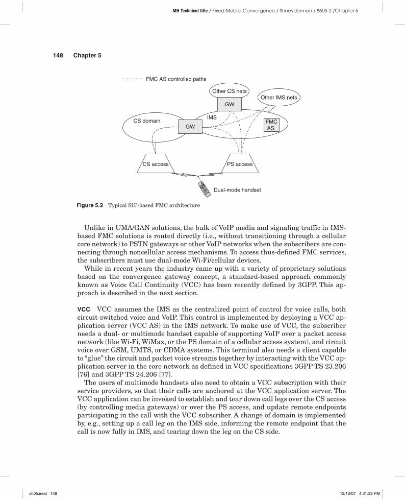
Today’s typical IMS and SIP VoIP FMC solutions are based on the combination of VoWi-Fi access and IMS core with cellular infrastructure tied together by means of a certain Convergence Gateway function and an FMC application server, anchoring calls across the domains (see Figure 5.2). Such an AS and gateway serve as a hub for both SS7 and SIP signaling, allowing for call establishment between different types of terminals and handling of services and calls placed to VoWi-Fi clients through the cellular infrastructure.
ch05.indd 147 12/12/07 4:31:37 PM
148 Chapter 5
MH Technical title / Fixed Mobile Convergence / Shneyderman / 8606-2 /Chapter 5
Unlike in UMA/GAN solutions, the bulk of VoIP media and signaling traffic in IMS-based FMC solutions is routed directly (i.e., without transitioning through a cellular core network) to PSTN gateways or other VoIP networks when the subscribers are con-necting through noncellular access mechanisms. To access thus-defined FMC services, the subscribers must use dual-mode Wi-Fi/cellular devices.
While in recent years the industry came up with a variety of proprietary solutions based on the convergence gateway concept, a standard-based approach commonly known as Voice Call Continuity (VCC) has been recently defined by 3GPP. This ap-proach is described in the next section.
VCC VCC assumes the IMS as the centralized point of control for voice calls, both circuit-switched voice and VoIP. This control is implemented by deploying a VCC ap-plication server (VCC AS) in the IMS network. To make use of VCC, the subscriber needs a dual- or multimode handset capable of supporting VoIP over a packet access network (like Wi-Fi, WiMax, or the PS domain of a cellular access system), and circuit voice over GSM, UMTS, or CDMA systems. This terminal also needs a client capable to “glue” the circuit and packet voice streams together by interacting with the VCC ap-plication server in the core network as defined in VCC specifications 3GPP TS 23.206 [76] and 3GPP TS 24.206 [77].
The users of multimode handsets also need to obtain a VCC subscription with their service providers, so that their calls are anchored at the VCC application server. The VCC application can be invoked to establish and tear down call legs over the CS access (by controlling media gateways) or over the PS access, and update remote endpoints participating in the call with the VCC subscriber. A change of domain is implemented by, e.g., setting up a call leg on the IMS side, informing the remote endpoint that the call is now fully in IMS, and tearing down the leg on the CS side.
Figure 5.2 Typical SIP-based FMC architecture
FMCAS
CS domainIMS
CS access PS access
GW
GWOther IMS nets
Other CS nets
Dual-mode handset
FMC AS controlled paths
ch05.indd 148 12/12/07 4:31:38 PM
The C in FMC 149
MH Technical title / Fixed Mobile Convergence / Shneyderman / 8606-2 /Chapter 5
Voice calls can be both originated and terminated by a VCC subscriber camped on one or both of the CS networks or the IMS at any time. Therefore special procedures are needed to anchor the calls originated from the VCC subscriber and to terminate calls destined to a VCC subscriber. Call termination implies selecting onto which do-main to try and deliver the call first, so a domain selection process is required while terminating calls. Call origination also requires the VCC UE to determine onto which domain to place the call (if more than one is available). In both termination and origi-nation, operator policies and user preferences come into play and become part of the VCC service definition offered by the operator.
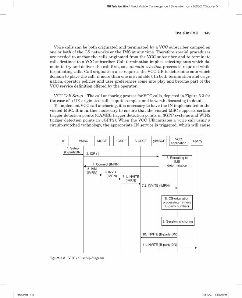
VCC Call Setup The call anchoring process for VCC calls, depicted in Figure 5.3 for the case of a UE originated call, is quite complex and is worth discussing in detail.
To implement VCC call anchoring, it is necessary to have the IN implemented in the visited MSC. It is further necessary to ensure that the visited MSC supports certain trigger detection points (CAMEL trigger detection points in 3GPP systems and WIN2 trigger detection points in 3GPP2). When the VCC UE initiates a voice call using a circuit-switched technology, the appropriate IN service is triggered, which will cause
Figure 5.3 VCC call setup diagram
S-CSCF VCCapplication
1. Setup(B-partyDN)
I-CSCFMGCFVMSCUE gsmSCF
2. IDP ( )
4. Connect (IMRN)5. IAM(IMRN) 6. INVITE
(IMRN) 7.1. INVITE(IMRN)
7.2. INVITE (IMRN)
10. INVITE (B-party DN)
9. Session anchoring
8. CS-originationprocessing (retrieve
B-party number)
3. Rerouting toIMS
determination
11. INVITE (B-party DN)
B-party
ch05.indd 149 12/12/07 4:31:39 PM
150 Chapter 5
MH Technical title / Fixed Mobile Convergence / Shneyderman / 8606-2 /Chapter 5
the MSC to query the gsm-SCF (in 3GPP systems, or the equivalent IN Service Control Point in 3GPP2 systems) to obtain the address to route the call to an MGCF, for an-choring and subsequent handling by the IMS. The address used to route the call to the correct MGCF provided by the gsm-SCF is called the IMS routing number (IMRN). This number is conceptually similar to the MSRN used in GSM to route incoming calls to the correct serving MSC for a mobile subscriber.
The MGCF then starts a conventional SIP call setup over the IMS core by sending a SIP INVITE toward an I-CSCF using the IMRN as the called party address. The I-CSCF or the S-CSCF (based on initial filter criteria) then invokes the VCC application by forwarding this SIP INVITE to it. Upon reception of the INVITE, the VCC applica-tion concludes the anchoring by forwarding the SIP invite back to the S-CSCF with the address of the called party instead of the IMRN. The S-CSCF forwards this SIP message in the direction of the called party.
This approach requires the allocation of the IMRN to the VCC subscriber at call setup, and a mapping of IMRN to the called party number to be available at the VCC applica-tion server. At the end of this transaction, IMS stores a state corresponding to this call.
It should be noted that the called party for such a call may be a PSTN or circuit cel-lular handset, so another MGCF needs to be involved in the call on the called party side or perhaps in some VoIP peering location. For calls initiated in IMS, the anchoring is simple and implies involving the VCC application in the handling of SIP sessions initiated by dual-mode UE. Note that not all SIP sessions traversing a CSCF and originated by a SIP endpoint are anchored at the VCC application, only those that are related to a voice call, which S-CSCF can discover by analyzing the SDP carried in SIP invite messages.
Once the call state is anchored in the VCC application, its Domain Transfer Function (see the next section) begins acting as a SIP B2BUA and assumes control of the access leg of the call (toward the VCC UE) and of the remote leg of the call (toward the peer of the VCC UE in the voice call). Voice calls bound for VCC subscribers in IMS can also be anchored following similar procedures.9
Domain Selection When a call is inbound for a VCC subscriber, the VCC applica-tion must select whether to try to reach the UE via a CS or PS technology. The act of making this decision is known as domain selection in 3GPP jargon. The incom-ing calls themselves can be originated either from another IMS network or from a CS network. In the latter case an MGCF in IMS core would always be involved in the call path toward the VCC subscriber. The specific way a gateway MSC (GMSC) routes the call toward the MGCF and the criteria that could drive the selection are not mandated in the standards. For example, it could be based on assigning blocks of numbers to VCC subscribers.
The selected domain may not be the one the UE is currently camped on, as in fact, the decision is taken in the home network. Nor is it possible to accurately keep track
9 Interested readers are invited to explore the details available in the 3GPP specifications [76] [77].
ch05.indd 150 12/12/07 4:31:39 PM
The C in FMC 151
MH Technical title / Fixed Mobile Convergence / Shneyderman / 8606-2 /Chapter 5
of location and access technology attachment status and reachability. If the attempt to contact the VCC UE fails in the selected domain, the UE is contacted in the other domain. If failure occurs in both domains, the call attempt fails.
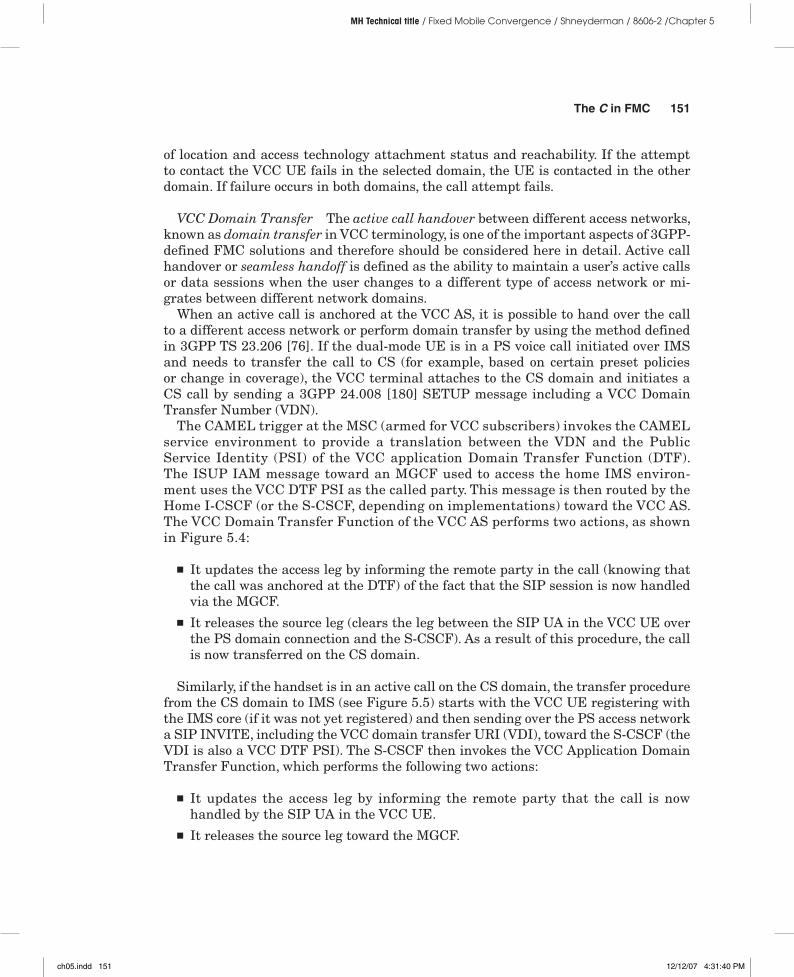
VCC Domain Transfer The active call handover between different access networks, known as domain transfer in VCC terminology, is one of the important aspects of 3GPP-defined FMC solutions and therefore should be considered here in detail. Active call handover or seamless handoff is defined as the ability to maintain a user’s active calls or data sessions when the user changes to a different type of access network or mi-grates between different network domains.
When an active call is anchored at the VCC AS, it is possible to hand over the call to a different access network or perform domain transfer by using the method defined in 3GPP TS 23.206 [76]. If the dual-mode UE is in a PS voice call initiated over IMS and needs to transfer the call to CS (for example, based on certain preset policies or change in coverage), the VCC terminal attaches to the CS domain and initiates a CS call by sending a 3GPP 24.008 [180] SETUP message including a VCC Domain Transfer Number (VDN).
The CAMEL trigger at the MSC (armed for VCC subscribers) invokes the CAMEL service environment to provide a translation between the VDN and the Public Service Identity (PSI) of the VCC application Domain Transfer Function (DTF). The ISUP IAM message toward an MGCF used to access the home IMS environ-ment uses the VCC DTF PSI as the called party. This message is then routed by the Home I-CSCF (or the S-CSCF, depending on implementations) toward the VCC AS. The VCC Domain Transfer Function of the VCC AS performs two actions, as shown in Figure 5.4:
■ It updates the access leg by informing the remote party in the call (knowing that the call was anchored at the DTF) of the fact that the SIP session is now handled via the MGCF.
■ It releases the source leg (clears the leg between the SIP UA in the VCC UE over the PS domain connection and the S-CSCF). As a result of this procedure, the call is now transferred on the CS domain.
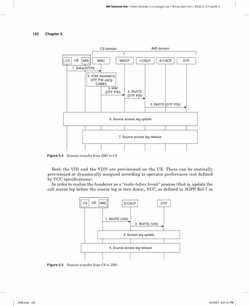
Similarly, if the handset is in an active call on the CS domain, the transfer procedure from the CS domain to IMS (see Figure 5.5) starts with the VCC UE registering with the IMS core (if it was not yet registered) and then sending over the PS access network a SIP INVITE, including the VCC domain transfer URI (VDI), toward the S-CSCF (the VDI is also a VCC DTF PSI). The S-CSCF then invokes the VCC Application Domain Transfer Function, which performs the following two actions:
■ It updates the access leg by informing the remote party that the call is now handled by the SIP UA in the VCC UE.
■ It releases the source leg toward the MGCF.
ch05.indd 151 12/12/07 4:31:40 PM
152 Chapter 5
MH Technical title / Fixed Mobile Convergence / Shneyderman / 8606-2 /Chapter 5
Both the VDI and the VDN are provisioned on the UE. These can be statically provisioned or dynamically assigned according to operator preferences (not defined by VCC specifications).
In order to realize the handover as a “make before break” process (that is, update the call access leg before the source leg is torn down), VCC, as defined in 3GPP Rel-7 in
Figure 5.4 Domain transfer from IMS to CS
UE MSC
1. Setup (VDN)
MGCFCS IMS DTFS-CSCF
5. INVITE (DTF PSI)
CS domain
3. IAM(DTF PSI)
I-CSCF
4. INVITE(DTF PSI)
2. VDN resolved toDTF PSI using
CAMEL
IMS domain
6. Source access leg update
7. Source access leg release
Figure 5.5 Domain transfer from CS to IMS
DTFS-CSCF
1. INVITE (VDI)
2. INVITE (VDI)
4. Source access leg release
UECS IMS
3. Access leg update
ch05.indd 152 12/12/07 4:31:41 PM
The C in FMC 153
MH Technical title / Fixed Mobile Convergence / Shneyderman / 8606-2 /Chapter 5
3GPP TS 23.206 [76] and 3GPP TS 24.206 [77], assumes that dual-mode terminals are capable of supporting concurrent access to the CS and PS technologies. If a sudden loss of coverage occurs in the access network supporting an active call, or if the terminal can only be active on one technology at a time, then the domain transfer will be based on “break before make,” and therefore will be less seamless.
Both the “make before break” and the “break before make” approaches assume that the alternative access network is available and therefore it is possible to hand over the active call by performing domain transfer. Needless to say, in the “break before make” case there could be perceptible interruption in the voice conversation.
VCC Applications Beyond FMC In addition to converging cellular and VoWi-Fi tele-phony, VCC can also be used to transfer calls between the CS and PS cellular domains when an operator decides to migrate parts of its network to cellular VoIP using tech-nologies such as UMTS HSPA, CDMA 1X EV-DO rev A (also known also as DOrA, or HRPD—high-rate packet data—specified in TIA IS-856 [78]), or LTE.
A UMTS terminal can maintain a CS call and the PS domain bearer needed to ac-cess the IMS concurrently active, thus meeting the applicability conditions of VCC Rel-7. A different discussion applies for the 3GPP2 VoIP deployment over DorA.10 Since DOrA is a PS-only system, not unlike Wi-Fi networks, Voice over IP is the only way to support telephony service in this technology. Dual-mode DOrA/CDMA 1x ter-minals can only have one of the CDMA 1x CS or DOrA PS bearers active at a time. Therefore, in this case, the 3GPP Rel-7 VCC specification cannot be directly applied in 3GPP2 environments.
The VCC operation for 3GPP2 1x/HRPD dual-mode terminals (as well as for 1x/Wi-Fi) is therefore different than 3GPP VCC and is defined in a separate document [79]. The problem of supporting continuity of a voice call with dual-mode terminals supporting a single transmitter/receiver (also known as “Single Radio” dual-mode terminals, not allowing the simultaneous transmission/reception over the two technologies) is a gen-eral problem that the industry will need to face in the course of transition toward PS-only cellular systems. So it can be expected that a generic, standard way to support single-radio, dual-mode terminals will be defined.
The support of VoIP in cellular environments is a broad new direction for the indus-try as a whole, helping it to converge toward a single IP-based network to provide all services. That’s why VCC received so much attention during its standardization process as a critical technology, not only enabling the short- and long-term objectives of FMC, but also providing building blocks for the technologies that follow on its footsteps.
Using elements such as VCC as a means to overcome the technical challenges of rolling out VoIP in a cellular environment, in a strict sense, does not represent an FMC application. Nevertheless, in our opinion, VCC has far-reaching impacts in its important role as a stepping stone in the evolution to fully converged seamless com-munications over a single IP-based network.
10 Note that many aspects of CS and PS call interaction in CDMA DOrevA are still not fully defined in 3GPP2 at the time of the book writing.
ch05.indd 153 12/12/07 4:31:41 PM
154 Chapter 5
MH Technical title / Fixed Mobile Convergence / Shneyderman / 8606-2 /Chapter 5
Practical Deployment Considerations Fixed operators that do not own and operate a cellular network, but still wish to provide their customers cellular services seamlessly converged with their fixed offerings, in most cases must rely on mobile virtual network operator (MVNO) relationships with a mobile operator. Their goal is to offer mobile ser-vices without owning the cellular access network and without giving up the ownership of subscribers to the cellular carriers. This can be achieved by establishing a wholesale agreement with a cellular operator, allowing the fixed operator to retain subscriber control. The FMC services enabled by such a relationship must therefore permit fixed operators to control HSS/HLR and back-end systems, allowing them to “own”:
■ All aspects of wireless account management and provisioning■ The ability to assign cellular subscriber numbers and identities■ Subscriber authorization and authentication■ Wireless applications and content hosting
The IMS and VCC architectures provide sufficient flexibility to satisfy these require-ments. In the case of MVNO, mobile networks, as seen by the FMC fixed-line operator, become simply roaming partners.
The issue of synchronization or “centralized service control” is a very important one when the IMS-based VCC FMC solution is deployed, as the CS domain’s supplementary services are working separately from the IMS-based simulation of the same services when the UE is on the IMS side, unless they are synchronized in a proprietary man-ner, or the service control is fully provided by the IMS. The latter option is still being standardized in 3GPP, and it represents a very important building block for the deliv-ery of an FMC service fully compliant with the IMS framework and providing enough flexibility for fixed and mobile operators to enter in creative partnerships.
In contrast to IMS, solutions such as UMA/GAN do not allow a wireline carrier to ex-ert control over cellular subscribers, essentially keeping the cellular operator in charge at all times. Furthermore, the UMA/GAN solution only addresses the GSM operator’s markets, effectively making IMS VCC the only standards-based technology for FMC application by 3GPP2 operators. Having said that, we must recognize that such a nar-row focus of the UMA/GAN standard made it extremely attractive for a specific target segment, that is, GSM operators, and caused it to become the foundation for the first commercially successful FMC deployments.
The following section considers the UMA/GAN technology in detail.
UMA/GAN
The idea of connecting to the GSM/GPRS core network via wireless access technologies using an unlicensed spectrum, such as Bluetooth or Wi-Fi combined with broadband, to deliver the same services as in the licensed spectrum always looked quite attractive to cellular network operators. These operators were willing to combine or extend their tra-ditional service offerings over GSM cellular access with the inexpensive coverage that can be achieved by other technologies such as those provided by Bluetooth or Wi-Fi.
ch05.indd 154 12/12/07 4:31:41 PM

The C in FMC 155
MH Technical title / Fixed Mobile Convergence / Shneyderman / 8606-2 /Chapter 5
This approach was particularly appealing to operators who can offer both cellular access and wireline access based on DSL or cable to their customers, so that their sub-scribers could potentially access their fixed and mobile services with the same dual-mode device. It then comes as no surprise that British Telecom, at the time when it still owned its cellular operations arm, BT Cellnet, now branded as O2, part of Telefonica (the Spanish operator, with fixed and mobile operations across Europe and Latin America), was the first company that started to actively investigate possible solutions and drive standardization of this technology.
Some time later, a consortium of companies, under the leadership of BT and other industry players, developed the Unlicensed Mobile Access (UMA) technology. This con-sortium was initiated in January 2004. The result of this work was the publication of an open set of technical specifications for extending mobile voice and data GSM/GPRS services over unlicensed spectrum technologies (including both Bluetooth and Wi-Fi). When this result was achieved, this alliance of companies encouraged these specifica-tions to be adopted by 3GPP. In 2005, when the UMA technology was finally adopted by the 3GPP, it was renamed to Generic Access Network, or GAN. The terms UMA and GAN are now used interchangeably to refer to the same technology, and undoubtedly UMA will remain in the technical dictionary of many in the industry for quite some time, although the standard only speaks of GAN.
Overview The UMA/GAN essentially extends the GSM/GPRS services over the Bluetooth or Wi-Fi radio interfaces, and in general over any IP network handled ac-cording to GAN specifications, through a blend of VoIP technology and UMA/GAN-defined tunneling and signaling protocols. As we already mentioned, UMA/GAN is a GSM-specific technology and therefore can be used only in conjunction with the GSM/GPRS core network, in the profile defined by 3GPP to serve the GSM/EDGE Radio Access Network (GERAN), i.e., via the A and Gb interfaces. By supporting GSM voice and data services over Wi-Fi- or Bluetooth-based IP access, UMA/GAN provides a logical extension to the existing 3GPP systems, allowing operators to re-alize all the benefits of FMC. UMA/GAN technology aims also at allowing seamless handover between wireless local area networks running in an unlicensed spectrum, such as Wi-Fi or Bluetooth, and wide area cellular networks using dual-mode, GAN/UMA-capable mobile phones. Again, the wireless local area component of GAN/UMA may be based on any technology supporting IP connectivity, as specified in 3GPP TS 43.318 [80].
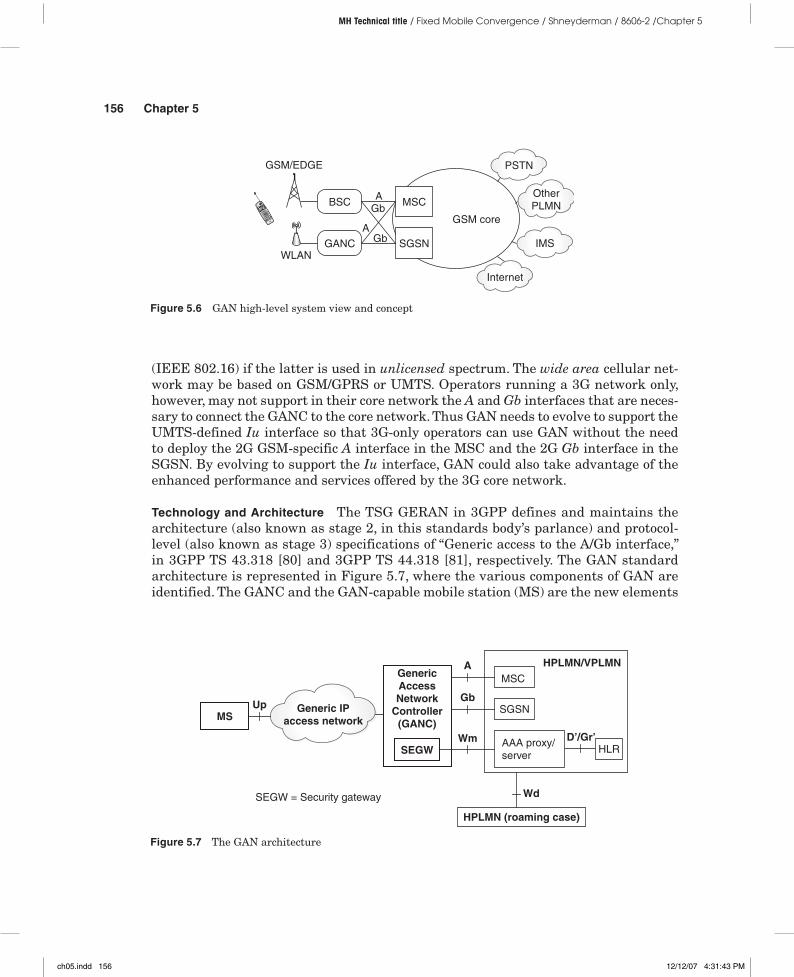
The traffic to and from a GAN/UMA terminal is routed over a GAN/UMA-defined interface to a GAN controller (GANC) (or a UMA network controller [UNC], in the legacy terminology), which appears to the GSM packet core as an ordinary base sta-tion controller (BSC). The GANC main function is to convert GAN signaling and media to a regular GSM voice call made over the GSM A interface. The GANC also converts the GAN data channel into a regular Gb interface–based GPRS packet data bearer service routed to the SGSN. Figure 5.6 clarifies the way GAN operates at a high level.
Under the GAN definition, the local area wireless network may be based on un- licensed spectrum technologies such as Bluetooth or Wi-Fi (IEEE 802.11)—or WiMAX
ch05.indd 155 12/12/07 4:31:42 PM
156 Chapter 5
MH Technical title / Fixed Mobile Convergence / Shneyderman / 8606-2 /Chapter 5
(IEEE 802.16) if the latter is used in unlicensed spectrum. The wide area cellular net-work may be based on GSM/GPRS or UMTS. Operators running a 3G network only, however, may not support in their core network the A and Gb interfaces that are neces-sary to connect the GANC to the core network. Thus GAN needs to evolve to support the UMTS-defined Iu interface so that 3G-only operators can use GAN without the need to deploy the 2G GSM-specific A interface in the MSC and the 2G Gb interface in the SGSN. By evolving to support the Iu interface, GAN could also take advantage of the enhanced performance and services offered by the 3G core network.
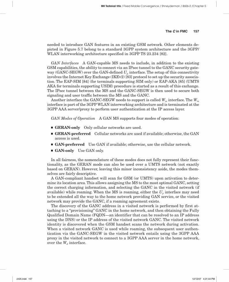
Technology and Architecture The TSG GERAN in 3GPP defines and maintains the architecture (also known as stage 2, in this standards body’s parlance) and protocol-level (also known as stage 3) specifications of “Generic access to the A/Gb interface,” in 3GPP TS 43.318 [80] and 3GPP TS 44.318 [81], respectively. The GAN standard architecture is represented in Figure 5.7, where the various components of GAN are identified. The GANC and the GAN-capable mobile station (MS) are the new elements
Figure 5.6 GAN high-level system view and concept
GSM/EDGE
BSC
GANCWLAN
AGb
GbA
MSC
SGSN
GSM core
Internet
IMS
OtherPLMN
PSTN
Figure 5.7 The GAN architecture
Generic IPaccess networkMS
Up
GenericAccessNetwork
Controller(GANC)
SEGW
HPLMN (roaming case)
SEGW = Security gateway
HPLMN/VPLMN
MSC
SGSN
AAA proxy/server
HLR
A
Gb
Wm D’/Gr’
Wd
ch05.indd 156 12/12/07 4:31:43 PM
The C in FMC 157
MH Technical title / Fixed Mobile Convergence / Shneyderman / 8606-2 /Chapter 5
needed to introduce GAN features in an existing GSM network. Other elements de-picted in Figure 5.7 belong to a standard 3GPP system architecture and the 3GPP/WLAN interworking architecture specified in 3GPP TS 23.234 [82].
GAN Interfaces A GAN-capable MS needs to include, in addition to the existing GSM capabilities, the ability to connect via an IPsec tunnel to the GANC security gate-way (GANC-SEGW) over the GAN-defined Up interface. The setup of this connectivity involves the Internet Key Exchange (IKEv2) [83] protocol to set up the security associa-tion. The EAP-SIM [84] (for terminals supporting SIM only) or EAP-AKA [85] (UMTS AKA for terminals supporting USIM) procedure is started as a result of this exchange. The IPsec tunnel between the MS and the GANC-SEGW is then used to secure both signaling and user traffic between the MS and the GANC.
Another interface the GANC-SEGW needs to support is called Wm interface. The Wm interface is part of the 3GPP WLAN interworking architecture and is terminated at the 3GPP AAA server/proxy to perform user authentication at the IP access layer.
GAN Modes of Operation A GAN MS supports four modes of operation:
■ GERAN-only Only cellular networks are used.■ GERAN-preferred Cellular networks are used if available; otherwise, the GAN
access is used.■ GAN-preferred Use GAN if available; otherwise, use the cellular network.■ GAN-only Use GAN only.
In all fairness, the nomenclature of these modes does not fully represent their func-tionality, as the GERAN mode can also be used over a UMTS network (not exactly based on GERAN). However, leaving this minor inconsistency aside, the modes them-selves are fairly descriptive.
A GAN-compliant handset will scan for GSM (or UMTS) upon activation to deter-mine its location area. This allows assigning the MS to the most optimal GANC, setting the correct charging information, and selecting the GANC in the visited network (if available) while roaming. When the MS is roaming, either the Up interface may need to be extended all the way to the home network providing GAN service, or the visited network may provide the GANC, if a roaming agreement exists.
The discovery of the GANC address in a visited network is performed by first at-taching to a “provisioning” GANC in the home network, and then obtaining the Fully Qualified Domain Name (FQDN—an identifier that can be resolved to an IP address using the DNS) or the IP address of the visited network GANC. The visited network identity is discovered when the GSM handset scans the network during activation. When a visited network GANC is used while roaming, the subsequent user authen-tication via the GANC-SEGW in the visited network entails using the 3GPP AAA proxy in the visited network to connect to a 3GPP AAA server in the home network, over the Wd interface.
ch05.indd 157 12/12/07 4:31:44 PM

158 Chapter 5
MH Technical title / Fixed Mobile Convergence / Shneyderman / 8606-2 /Chapter 5
Circuit and Packet Services User Plane For circuit-switched services, the GANC per-forms the following user plane (Up) functions, depicted in Figure 5.8, which represent the GAN CS user plane protocol stacks:
■ Termination of the Up IPsec tunnels, which carry the AMR/RTP/UDP/IP VoIP packets from the MS. In the protocol stack in Figure 5.8, these VoIP packets are using the “remote IP layer,” which is the IP stack logically associated to the inner IP packets of the IPsec tunnel’s virtual network interface.
■ Termination of AMR/RTP/UDP/IP and framing into AMR before sending voice frames over the A interface using the necessary encoding:■ If Transcoder-Free Operation (TrFO, specified in 3GPP TS 23.153 [185]) is not
supported, then transcoding between the AMR and PCM needs to be performed for correct operation over the A interface.
■ If TrFO is supported, no transcoding is necessary at GANC, unless a common codec cannot be negotiated with the remote MS or transcoder.
For Packet Domain services, the GANC terminates the IPsec tunnels over the Up interface and relays packets over the bearers of the Gb interface toward the SGSN.
Circuit and Packet Services Control Plane On the control plane, the GANC (and SEGW) provides:
■ Termination of the Up IPsec tunnels■ MS/GANC mutual authentication, via IKEv2+EAP-SIM/AKA, and the support of
the authentication procedures subset of the Wm interface specified in 3GPP TS 29.234 [186]
Figure 5.8 GAN CS user plane protocol stacks
Up
Speechbearer
Accesslayers
Generic IPnetwork
IPsec ESP
GANCMS
Speechbearer
Physicallayers
MSC
A
Physicallayers
Codec/rateadaptation
Transcoding(if necessary)
Codec/rateadaptation
Accesslayers
Transport IP Transport IPTransport IP
RTP/UDP RTP/UDP
Accesslayers
Remote IP
IPsec ESP
Remote IP
IWF(if necessary)
ch05.indd 158 12/12/07 4:31:45 PM
The C in FMC 159
MH Technical title / Fixed Mobile Convergence / Shneyderman / 8606-2 /Chapter 5
■ Transparent transfer of GSM/GPRS Layer 3 signaling messages between the MS and GSM/GPRS core network
■ Registration for GAN access■ Providing GAN system information■ Establishment, administration, and release of control and user plane bearers
between the MS and the GANC■ Support for paging, handover, and PS handover procedures
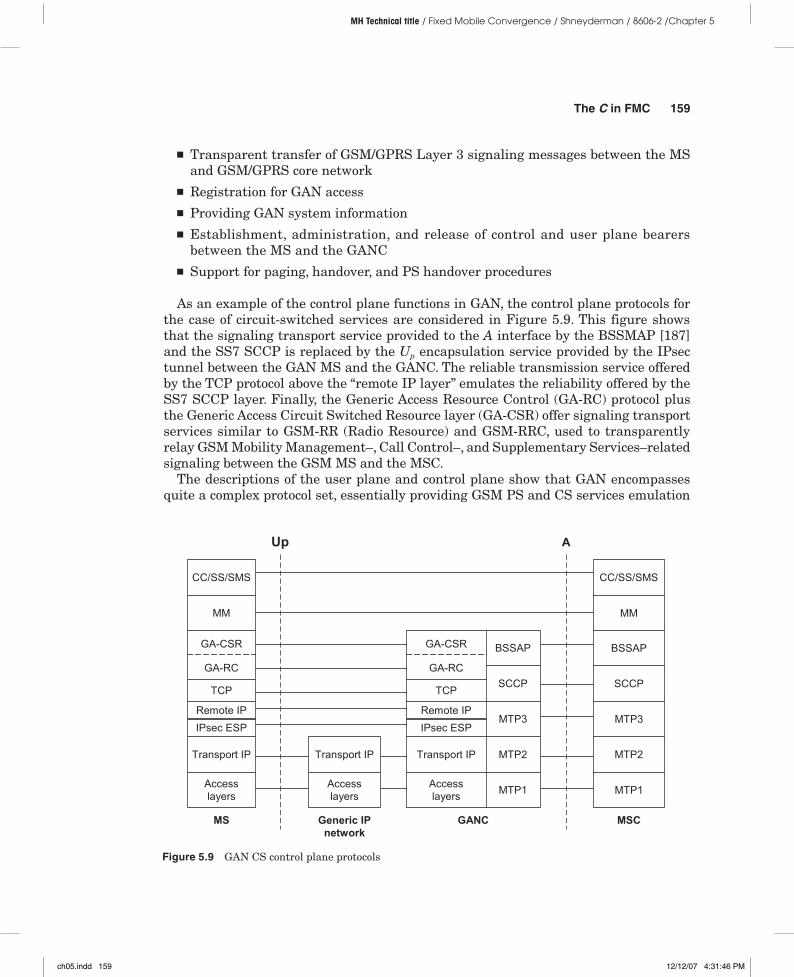
As an example of the control plane functions in GAN, the control plane protocols for the case of circuit-switched services are considered in Figure 5.9. This figure shows that the signaling transport service provided to the A interface by the BSSMAP [187] and the SS7 SCCP is replaced by the Up encapsulation service provided by the IPsec tunnel between the GAN MS and the GANC. The reliable transmission service offered by the TCP protocol above the “remote IP layer” emulates the reliability offered by the SS7 SCCP layer. Finally, the Generic Access Resource Control (GA-RC) protocol plus the Generic Access Circuit Switched Resource layer (GA-CSR) offer signaling transport services similar to GSM-RR (Radio Resource) and GSM-RRC, used to transparently relay GSM Mobility Management–, Call Control–, and Supplementary Services–related signaling between the GSM MS and the MSC.
The descriptions of the user plane and control plane show that GAN encompasses quite a complex protocol set, essentially providing GSM PS and CS services emulation
Figure 5.9 GAN CS control plane protocols
GANCMS
SCCPSCCP
MTP3
MM MM
Transport IP MTP2
MTP1
MTP3
MTP1
Up
Accesslayers
Transport IP
CC/SS/SMS
Generic IPnetwork
BSSAP
Remote IP
MSC
A
BSSAP
Accesslayers
MTP2
CC/SS/SMS
Remote IPIPsec ESP IPsec ESP
TCP
GA-RC
GA-CSR
TCP
GA-CSR
GA-RC
Transport IP
Accesslayers
ch05.indd 159 12/12/07 4:31:46 PM
160 Chapter 5
MH Technical title / Fixed Mobile Convergence / Shneyderman / 8606-2 /Chapter 5
over a packet transport. Needless to say, the reliance on the GSM core has represented both the strength and the weakness of this solution. The following section evaluates the pros and cons of UMA/GAN, thus providing an insight on the GAN applicability to real-life deployments.
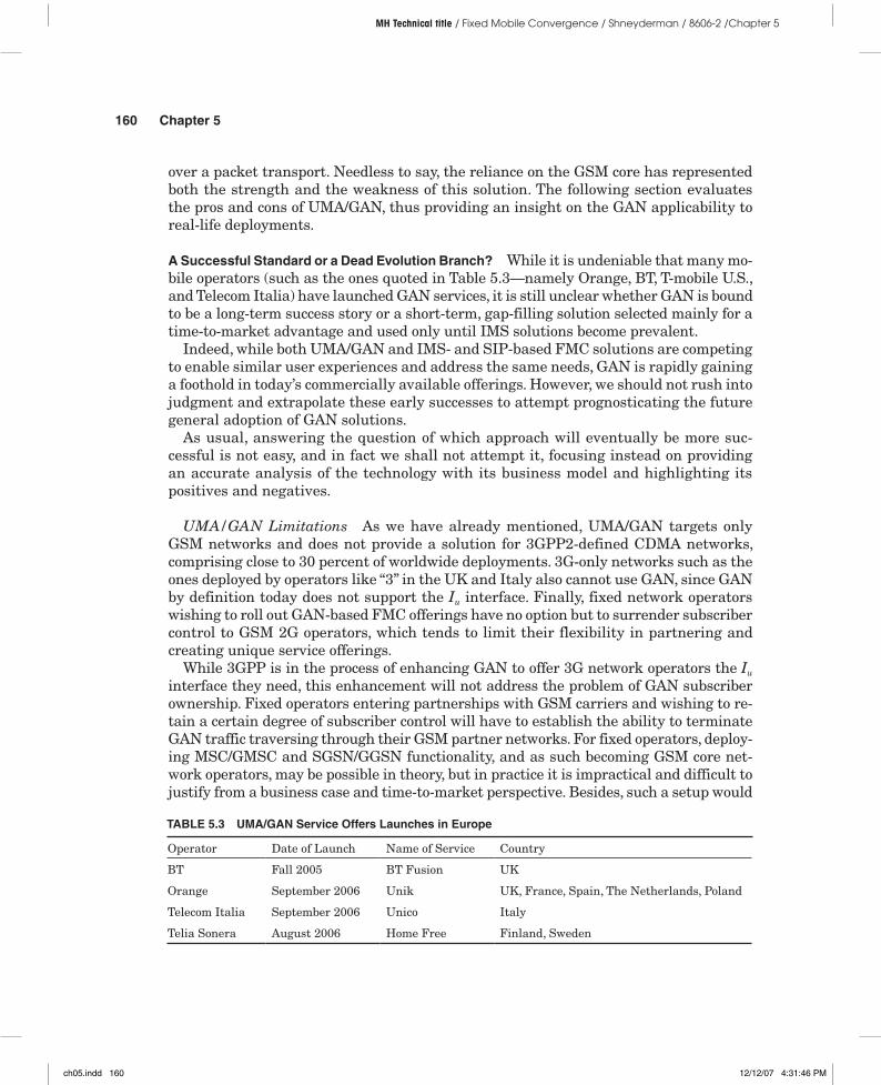
A Successful Standard or a Dead Evolution Branch? While it is undeniable that many mo-bile operators (such as the ones quoted in Table 5.3—namely Orange, BT, T-mobile U.S., and Telecom Italia) have launched GAN services, it is still unclear whether GAN is bound to be a long-term success story or a short-term, gap-filling solution selected mainly for a time-to-market advantage and used only until IMS solutions become prevalent.
Indeed, while both UMA/GAN and IMS- and SIP-based FMC solutions are competing to enable similar user experiences and address the same needs, GAN is rapidly gaining a foothold in today’s commercially available offerings. However, we should not rush into judgment and extrapolate these early successes to attempt prognosticating the future general adoption of GAN solutions.
As usual, answering the question of which approach will eventually be more suc-cessful is not easy, and in fact we shall not attempt it, focusing instead on providing an accurate analysis of the technology with its business model and highlighting its positives and negatives.
UMA/GAN Limitations As we have already mentioned, UMA/GAN targets only GSM networks and does not provide a solution for 3GPP2-defined CDMA networks, comprising close to 30 percent of worldwide deployments. 3G-only networks such as the ones deployed by operators like “3” in the UK and Italy also cannot use GAN, since GAN by definition today does not support the Iu interface. Finally, fixed network operators wishing to roll out GAN-based FMC offerings have no option but to surrender subscriber control to GSM 2G operators, which tends to limit their flexibility in partnering and creating unique service offerings.
While 3GPP is in the process of enhancing GAN to offer 3G network operators the Iu interface they need, this enhancement will not address the problem of GAN subscriber ownership. Fixed operators entering partnerships with GSM carriers and wishing to re-tain a certain degree of subscriber control will have to establish the ability to terminate GAN traffic traversing through their GSM partner networks. For fixed operators, deploy-ing MSC/GMSC and SGSN/GGSN functionality, and as such becoming GSM core net-work operators, may be possible in theory, but in practice it is impractical and difficult to justify from a business case and time-to-market perspective. Besides, such a setup would
Operator Date of Launch Name of Service Country
BT Fall 2005 BT Fusion UK
Orange September 2006 Unik UK, France, Spain, The Netherlands, Poland
Telecom Italia September 2006 Unico Italy
Telia Sonera August 2006 Home Free Finland, Sweden
TABLE 5.3 UMA/GAN Service Offers Launches in Europe
ch05.indd 160 12/12/07 4:31:46 PM
The C in FMC 161
MH Technical title / Fixed Mobile Convergence / Shneyderman / 8606-2 /Chapter 5
require the establishment of new roaming arrangements with other 3GPP operators, which per se is a significant effort. In most cases this leaves wireline operators no choice but to fully outsource GAN-based FMC solutions to the cellular operator they partner with, and be content with back-end (for example, billing, Web services) ownership.
GAN limitations do not stop here. Fixed operators who have deployed GAN in partner-ship with a GSM operator that operates the GAN need in any case to route their fixed-line calls through a partner’s GSM network core, a less-than-desirable scenario, especially in view of the deployment of an IMS core, which was designed to enable complete offload of the voice traffic from the cellular CS core. In general, the necessity to always route GAN traffic over the GSM core, even to or from the user in the home zone connecting through un-licensed non-GSM access, results in limiting cost benefits for operators (at least on the core-network-side utilization)—one of the main drivers behind FMC solutions deployment.
Furthermore, the lack of support for many PBX features (such as IP Centrex) has ruled out the adoption of GAN in enterprise environments, prompting the introduction of other types of FMC solutions not described in detail in this book, but mostly based on extending PBX capabilities in a proprietary manner.
Finally, the GAN-defined VoIP traffic generated by subscribers in the home zone is turned into a circuit-switched TDM voice by the GANC. The resulting possible “double”11 encoding conversion, however wasteful, is necessary to offer the A interface to an MSC to support seamless handover, one of the main properties of a well-implemented FMC solution. Note that in principle it is possible to offer a true end-to-end cellular VoIP ser-vice over the GPRS domain of the GAN (assuming that QoS and bandwidth issues were somehow addressed), but then it would be impossible to hand over calls to the cellular network, as VoIP today is not commonly offered in 3GPP systems PS domain.
UMA/GAN Benefits Our discussion in this section so far has focused on the poten-tial limitations of GAN. In fact you might justly wonder how GAN could have been so successful with such a vast number of shortcomings. The answers become evident if one understands GAN focus and analyzes significant benefits this technology has to offer to 3GPP operators.
First and foremost, GAN looks like a logically straightforward extension of GSM ser-vice offerings, supporting all GSM supplementary services and providing comparable voice quality, which makes for a truly seamless user experience. GAN is also easy to deploy, especially for wireless operators, as the GSM core infrastructure would treat it as just another access method along with UTRAN and GERAN (that is, aside from the need to manage the GAN network and collect additional charging information that needs to be handled by the billing subsystem).
Finally, commercial implementation of a GAN-based FMC solution, which essentially requires the installation of only one new network element, GANC, is far less risky and quicker to the market than a full-blown IMS infrastructure (yet to be fully defined, integrated, and tested in most operators’ networks).
11 AMR to PCM and then back to AMR, if the remote end in the call is a GSM or GAN MS, or even to analog if the remote end is a traditional analog phone.
ch05.indd 161 12/12/07 4:31:47 PM
162 Chapter 5
MH Technical title / Fixed Mobile Convergence / Shneyderman / 8606-2 /Chapter 5
GAN-based Convergence In this section we will consider practical aspects of the imple-mentation of GAN-based convergence solutions.
Wi-Fi Access With a GAN-based GSM/Wi-Fi dual-mode handset, it is possible to place and receive calls over the cellular network or over the broadband access network supporting the GAN access. As there are no specific requirements on the Wi-Fi access point or type of broadband service used by the GAN subscriber, the Wi-Fi access options may include a residential or small office DSL, cable, or fiber broadband connection with the appropriate CPE, a Wi-Fi hotspot, or a college campus WLAN deployment. Upon entering a Wi-Fi hotspot, or a home zone Wi-Fi coverage area at home or at a small office, the handset gains wireless access over the Wi-Fi network. This may require configuring the GAN terminal with the appropriate SSID of the Wi-Fi networks and possibly other parameters as described in the preceding chapter.
For example, in some cases, the Wi-Fi access points may implement 802.1x security and require authentication for wireless access, and in this case support for an EAP ex-change using EAP-SIM or EAP-AKA may be needed to provide access control. The opera-tor may also use a AAA server to implement a set of policies governing the access over nonlicensed networks based on location, time of day, presence, or other parameters.
Once the dual-mode GAN terminal is connected to the Wi-Fi network, an IPsec tun-nel is established between the GAN UE and the GANC. The GANC includes a security gateway authenticating the terminal and providing access control. This authentication also allows the AAA server to check the location of the user based on the correlation with information derived from the network access authentication and the IP address. This information is useful for charging purposes and also for allowing location-based and user-profile-based access control. Note that this level of authentication is different from authentication used to gain Wi-Fi access.
The peculiarities of Wi-Fi-based GAN are generally limited to the ones described already, as the GAN architecture in principle varies little between different unlicensed wireless access technologies used to obtain IP connectivity. Similar considerations also apply to Bluetooth access, the second most popular GAN mode of operation in the home environment after Wi-Fi, which is described in the next section. One significant difference in Wi-Fi and Bluetooth in practical GAN solution implementation is that Wi-Fi proves to be quite uniquely positioned for public hotspot deployments, whereas Bluetooth is not really applicable in that environment.
Bluetooth Access Despite proliferation of Wi-Fi, the initial deployments of GAN have taken place with the GSM/Bluetooth dual-mode terminals, as the availability of GSM/Wi-Fi terminals until recently has been quite limited especially in mid-tier con-sumer price segments, making positioning GAN solutions with mainstream subscrib-ers difficult. Another issue with dual-mode GSM/Wi-Fi handsets has been (and still is) their poor battery life while in Wi-Fi access mode, sometimes measuring at 50 percent that of GSM, especially in standby, where constant AP handshaking is necessary.
In these early deployments, Bluetooth GAN terminals based on the regular Bluetooth-equipped cellular phones, needing little or no modification to support UMA/GAN clients, were logically selected to fill the gap. An example of such early launches
ch05.indd 162 12/12/07 4:31:47 PM
The C in FMC 163
MH Technical title / Fixed Mobile Convergence / Shneyderman / 8606-2 /Chapter 5
was the BT Fusion service, initially named “Bluephone,” which started with Bluetooth GAN handsets and only recently expanded to Wi-Fi.
While offering these and a few other advantages, the deployment of Bluetooth so-lutions still requires a Bluetooth hub in the home zone, grooming the GAN traffic toward the broadband access network. Bluetooth hubs have a nasty habit of “seizing” the handset, often without regard for subscriber preferences, as the support for spe-cific Bluetooth profiles in handsets varies significantly between manufacturers. Thus GAN Bluetooth hubs were frequently found “dueling” with Bluetooth headsets, or in the opposite extreme case the service required the subscribers to manually switch over the handset to and from headsets and hubs. The situation got so bad that in some cases the only available solution for operators was to provide the GAN users with a corded headset and restrict them from using Bluetooth headsets and other devices while in the home zone.
Let’s now continue with an overview of another vertically integrated convergence solution, based on the femtocell concept.
Femtocells
A femtocell is a modern, smaller scale, reincarnation of a nano- and picocell technology first introduced in the previous decade. Specifically, nanocells and picocells were initially brought to market in the late 1990s by companies like Nokia, Motorola, and Ericsson. Unfortunately these products were not well received. Among the reasons at the time were limited backhaul bandwidth, high equipment cost, and poorly chosen deployment strategy—a typical combination of factors for a technology ahead of its time.12
Femtocell solutions nowadays are used to convert traffic to and from standard cel-lular handsets in close proximity (typically up to 100 meters) and carry it over IP, reducing to a bare minimum the air portion of the cellular traffic and relieving opera-tors from the necessity to deploy expensive wide area cellular sites.
Essentially a femtocell is a miniaturized base station with the following characteristics:
■ Radiated power in the single-digit milliwatt range■ Capacity between four and ten simultaneous active calls■ Backhaul based on IP over broadband links■ Range around a hundred meters
Femtocells are typically designed to be installed in residential home zones or small offices. They are designed to provide the same service as any other base station to subscribers using standard cellular handsets.
12 Limited acceptance of IP at the time as a common Network layer communication technology for voice and data, and also for wireless access backhaul, may have also had its influence. The introduction of mass-market IP broadband access contributes to making deployment of femtocells quite practical and economical these days.
ch05.indd 163 12/12/07 4:31:48 PM

164 Chapter 5
MH Technical title / Fixed Mobile Convergence / Shneyderman / 8606-2 /Chapter 5
The value proposition behind femtocells is similar to that of the dual-mode solutions, addressing cost, capacity, and coverage issues for the operator—allowing the reduction of both CAPEX and OPEX—and in some ways convenience issues for the subscribers. Thus, at least in theory, this technology lends itself well to enabling many elements of the converged communication experience. We must note, however, that femtocell technology is difficult to apply to enable truly converged FMC solutions, as it does not support13 multimode (cellular plus some alternative access technology) terminals and access-independent communication, principally addressing the issues of limited indoor area coverage, and of the offload of traffic from congested licensed spectrum, using the same technology as wide area cellular networks.
Architecture A typical femtocell solution consists of two main component classes: the actual CPE femtocell and a backhaul component, usually a gateway or concentrator, converting femtocell output to media and signaling understood by the rest of the infra-structure. The functionality of such elements is somewhat similar to that of GANC.
Figure 5.10 provides a high-level view of a typical femtocell solution.Today’s femtocell backhaul architecture options include
■ A Modified RNC approach constituting tunneling an Iub interface to a modified cellular radio network controller (M-RNC)
■ A concentrator or controller approach supporting connectivity to a gateway rather than a direct RNC connection
■ A collapsed stack femtocell
13 At least at the time of this book’s writing.
Figure 5.10 High-level femtocell solution architecture
Broadbandnetwork
Cellularbackhaul
IP
PSTNCellularcore
Basestation
Cellularphone
BSC/RNC
BSC/RNC
Home zone
Cellularphone
Femtocell
Wide area
ch05.indd 164 12/12/07 4:31:49 PM
The C in FMC 165
MH Technical title / Fixed Mobile Convergence / Shneyderman / 8606-2 /Chapter 5
■ A UMA/GAN femtocell■ An IMS femtocell
Next we analyze and compare these approaches.
Modified RNC The Modified RNC14 option simply provides a way for a femtocell to connect directly to the operator’s UMTS RNC (or BSC in CDMA and GSM networks). The standard Iub transport protocol is emulated15 in this architecture to encapsulate voice traffic media and signaling in IP, tunnel it over a broadband connection, and ter-minate it at an Iub-compliant Modified RNC.
The femtocell traffic is different from that of a regular base station, in that the RNC may terminate E1/T1s from the Node-Bs and may not support the IP transport option; therefore, the RNC must be modified to accept IP–based Iub (defined in [86] [87] [88] [89] [90] [91] [92] [93]), hence the name: Modified RNC (M-RNC). Even with this necessary modification, this solution is the one introducing the fewest changes in the existing cellular infrastructure and, in many cases, is the easiest to deploy.
Note that one of the potential drawbacks of this solution is the RNC infrastructure scalability, as the existing RNCs are designed to support a limited number of base sta-tions and may not be able to accommodate the conceivably millions of femtocell connec-tions that could result from the “one femtocell in every home” campaign. So, different options are required to support these femtocells, also to take into account the fact that IPsec termination may be required to secure the path between the femtocell and the RNC. This is provided by the RNC concentrator.
Iub Concentrator The Iub concentrator approach was invented to address the draw-backs of Modified RNC solutions, specifically low scalability and the need to modify many RNCs in the existing infrastructure. As the name implies, the femtocells in this option connect to a highly scalable Iub concentrator terminating individual Iub tunnels (potentially protected by IPsec), converting it to the format friendly to the standard RNCs, as in Figure 5.11.
Some femtocell concentrator vendors even go as far as building controller function-ality into their products, allowing to connect them directly to the core. That approach enables them to offload RNCs when subscribers are using femtocells en mass, poten-tially at data rates and for durations and applications not common in the wide area, which would make the traditional traffic model used to size RNCs no longer valid and so congest existing RNCs’ capacity.
14 In this section we will refer to the interface used in UMTS to connect a UMTS Node-B to the RNC, but the equivalent interface used to connect base stations to their controllers in other technologies can be assumed mutatis mutandis (that is, applying the appropriate terminology applicable for the different technologies). In 3GPP technologies, we have chosen to focus on UMTS, as operators will focus on this technology, while not discounting 2G technologies, in the future evolution of their network.
15 The Iub interface is used in today’s cellular networks to connect UMTS base stations (Node-Bs) to UMTS RNCs.
ch05.indd 165 12/12/07 4:31:50 PM
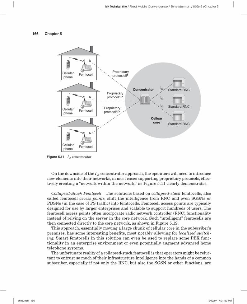
166 Chapter 5
MH Technical title / Fixed Mobile Convergence / Shneyderman / 8606-2 /Chapter 5
On the downside of the Iub concentrator approach, the operators will need to introduce new elements into their networks, in most cases supporting proprietary protocols, effec-tively creating a “network within the network,” as Figure 5.11 clearly demonstrates.
Collapsed-Stack Femtocell The solutions based on collapsed-stack femtocells, also called femtocell access points, shift the intelligence from RNC and even SGSNs or PDSNs (in the case of PS traffic) into femtocells. Femtocell access points are typically designed for use by larger enterprises and scalable to support hundreds of users. The femtocell access points often incorporate radio network controller (RNC) functionality instead of relying on the server in the core network. Such “intelligent” femtocells are then connected directly to the core network, as shown in Figure 5.12.
This approach, essentially moving a large chunk of cellular core in the subscriber’s premises, has some interesting benefits, most notably allowing for localized switch-ing. Smart femtocells in this solution can even be used to replace some PBX func-tionality in an enterprise environment or even potentially augment advanced home telephone systems.
The unfortunate reality of a collapsed-stack femtocell is that operators might be reluc-tant to entrust so much of their infrastructure intelligence into the hands of a common subscriber, especially if not only the RNC, but also the SGSN or other functions, are
Figure 5.11 Iub concentrator
Celluarcore
ConcentratorIub
Iub
Iub
Proprietaryprotocol/IP
Proprietaryprotocol/IP
Proprietaryprotocol/IP
Cellularphone
Femtocell
Cellularphone
Femtocell
Cellularphone
Femtocell
Standard RNC
Standard RNC
Standard RNC
ch05.indd 166 12/12/07 4:31:52 PM
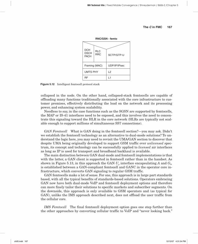
The C in FMC 167
MH Technical title / Fixed Mobile Convergence / Shneyderman / 8606-2 /Chapter 5
collapsed in the node. On the other hand, collapsed-stack femtocells are capable of offloading many functions traditionally associated with the core infrastructure to cus-tomer premises, effectively distributing the load on the network and its processing power, and enhancing system scalability.
Needless to say, in the case functions such as the SGSN are supported by femtocells, the MAP or IS-41 interfaces need to be exposed, and this involves the need to concen-trate this signaling toward the HLR in the core network (HLRs are typically not scal-able enough to support millions of simultaneous SS7 connections).
GAN Femtocell What is GAN doing in the femtocell section?—you may ask. Didn’t we establish the femtocell technology as an alternative to dual-mode solutions? To un-derstand the logic here, you may need to revisit the UMA/GAN section to discover that despite UMA being originally developed to support GSM traffic over unlicensed spec-trum, its concept and technology can be successfully applied to licensed air interfaces as long as IP is used for transport and broadband backhaul is available.
The main distinction between GAN dual-mode and femtocell implementations is that with the latter, a GAN client is supported in femtocell rather than in the handset. As shown in Figure 5.13, in this approach the GAN Up interface encapsulating A and Gb, is established between a GAN-compliant femtocell and GANC in the operator core in-frastructure, which converts GAN signaling to regular GSM traffic.
GAN femtocells make a lot of sense. For one, this approach is in large part standards based, with all the typical benefits of standards-based solutions. Operators embracing GAN now have both dual-mode VoIP and femtocell deployment options and therefore can more finely tailor their solutions to specific markets and subscriber segments. On the downside, this approach is only available to GSM operators and (as typical for GAN), unlike the IMS approach described next, does not offload the user traffic from the cellular core.
IMS Femtocell The final femtocell deployment option goes one step further than the other approaches by converting cellular traffic to VoIP and “never looking back.”
Figure 5.12 Intelligent femtocell protocol stack
RF
UMTS PHY
Framing (MAC)
DCHDSCHFACH
RNC/GSN - femto
RLCRRC
L1
L2
UDP/IP/IPsec
SCTP/GTP-U
ch05.indd 167 12/12/07 4:31:54 PM
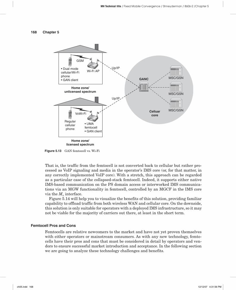
168 Chapter 5
MH Technical title / Fixed Mobile Convergence / Shneyderman / 8606-2 /Chapter 5
That is, the traffic from the femtocell is not converted back to cellular but rather pro-cessed as VoIP signaling and media in the operator’s IMS core (or, for that matter, in any correctly implemented VoIP core). With a stretch, this approach can be regarded as a particular case of the collapsed-stack femtocell. Indeed, it supports either native IMS-based communication on the PS domain access or interworked IMS communica-tions via an MGW functionality in femtocell, controlled by an MGCF in the IMS core via the Mn interface.
Figure 5.14 will help you to visualize the benefits of this solution, providing familiar capability to offload traffic from both wireless WAN and cellular core. On the downside, this solution is only suitable for operators with a deployed IMS infrastructure, so it may not be viable for the majority of carriers out there, at least in the short term.
Femtocell Pros and Cons
Femtocells are relative newcomers to the market and have not yet proven themselves with either operators or mainstream consumers. As with any new technology, femto-cells have their pros and cons that must be considered in detail by operators and ven-dors to ensure successful market introduction and acceptance. In the following section we are going to analyze these technology challenges and benefits.
Figure 5.13 GAN femtocell vs. Wi-Fi
Celluarcore
GANC
Up/IP
GSM
VoWi-Fi
Up/IP
• Dual modecellular/Wi-Fiphone• GAN client
Wi-Fi AP
Regularcellularphone
• UMAfemtocell• GAN client
MSC/GSN
MSC/GSN
MSC/GSN
Home zone/unlicensed spectrum
Home zone/licensed spectrum
ch05.indd 168 12/12/07 4:31:56 PM

The C in FMC 169
MH Technical title / Fixed Mobile Convergence / Shneyderman / 8606-2 /Chapter 5
Femtocell Limitations Let’s first consider femtocell challenges.
Standardization Despite the long history behind the whole mini–base station para-digm, as of today there are still no real standards associated with femtocells. The fem-tocell commercial offerings are therefore evolving as proprietary solutions, sometimes partially compliant to the existing 3GPP and 3GPP2 standards governing traditional cellular architectures.
As with any proprietary solutions, operators and consumers alike stand to benefit from their quicker time to market and more diverse sets of functionality. On the other hand, the femtocell manufacturers and suppliers will not be able to realize the econo-mies of scale associated with standardized solutions, a situation that is in turn bound to affect the femtocell costs already identified as one of the potential roadblocks to widespread deployment.
Spectrum Unlike Wi-Fi access points, femtocells by definition operate in licensed spectrums using standard cellular air interfaces and protocol technologies such as GSM, UMTS, or CDMA 1xEV-DO. As such, femtocells may only be deployed in areas where operators obtain spectrum licenses. That may make femtocell deployment prob-lematic, especially in the geographical border areas.
Also the subscribers will need to be educated on the difference between solutions operating in licensed versus unlicensed spectrums (e.g., femtocell vs. Wi-Fi hotspot), and be prohibited from operating their femtocell-handset combinations in areas where no licensed spectrum is available or where their operation is undesirable to carriers,
Figure 5.14 IMS femtocell
IMS core
P/S/I-CSCF
SIP/RTP/IP
SIP/RTP/IP
Cellularphone IMS
femtocell
Cellularphone IMS
femtocell
MG
MR
AS
HSS
ch05.indd 169 12/12/07 4:31:58 PM
170 Chapter 5
MH Technical title / Fixed Mobile Convergence / Shneyderman / 8606-2 /Chapter 5
such as in a different country or continent. To enforce such restrictions and prevent subscribers from turning femtocells into portable base stations, manufacturers often equip their products with GPS receivers and appropriate software capable of manag-ing16 femtocell operation according to location.
Other issues that need to be addressed for a typical device operating in a licensed spectrum include coexistence, interference, and communication with the rest of the cel-lular WAN, and automatic power control on par with regular cells.
Cost Cost had been one of the most serious hurdles the industry was unable to overcome with earlier miniaturized base-station forays. Operators naturally expect to distribute femtocells—correctly viewed as cellular infrastructure extensions—to the end users with poor home-zone coverage, in many cases essentially addressing the deficiencies in their service. In such environments many operators identified the top price before subsidies as no higher than around $300 or €200, in the Americas and Europe, respectively.
It’s worth noting that the impact of femtocell cost on carriers’ pricing decisions changes widely with a given operator’s distribution model. When femtocells are dis-tributed by a carrier as a remedy for coverage gaps, the costs are naturally expected to be absorbed by the carrier itself. In some cases, however, carriers may require (or allow) residential or enterprise subscribers to acquire or lease the equipment—similar to the current cable TV model. Finally, carriers perhaps may rent femtocells to organizations or individuals or share them to provide service in public locations—as with current tower-sharing arrangements.
Integration Issues Femtocells may certainly help fixed-to-mobile substitution, making it easier (and cheaper) for the subscribers to start using only their mobile phone (and service) for all of their communication needs. However, when it comes to FMC, femtocells may be difficult to integrate with the existing fixed services in use by subscribers, such as office PBX-based systems in enterprise environments or resi-dential multi-handset analog cordless systems or VoIP phones. Therefore, femtocell-based solutions are often likely to stay a step behind other FMC approaches such as dual-mode cellular/Wi-Fi methods, in terms of convenience and usability for many market segments (for example, for subscribers interested in using multiple types of devices in FMC family plans).17
To overcome these limitations, femtocell solutions will have to incorporate Wi-Fi access points and other functionalities that may make them more complex and drive their costs even higher, which in turn affects subscriber acceptance.
Benefits After reading the preceding section, you might think that femtocells are doomed even before being born. The reality, though, proves this conclusion premature,
16 Read: restricting.
17 See examples in the next chapter.
ch05.indd 170 12/12/07 4:32:00 PM
The C in FMC 171
MH Technical title / Fixed Mobile Convergence / Shneyderman / 8606-2 /Chapter 5
especially when applied to specific subscriber segments and markets. Operators looking for ways to deploy femtocells must therefore carefully select the deployment strategy and consider femtocells as an integral part of their existing infrastructure.
Femtocell technology benefits for equipment manufacturers, operators, and subscrib-ers are significant and diverse. By comparison with other FMC approaches, femtocells allow subscribers to use their existing devices to achieve many of the advantages prom-ised by FMC, such as excellent indoor coverage and home-zone pricing without the typi-cal limitations of dual-mode solutions. Such limitations might, for example, include the need for the users to upgrade to new, potentially more expensive dual-mode terminals, coupled with limited terminal selection.
Femtocells’ positive impact further increases as 3G solutions proliferate. This is mainly due to 3G systems’ higher frequencies, subsequently higher indoor signal ob-stacle path loss, and ensuing signal degradation with the increased number of indoor users of 3G service—an all-too-common scenario in urban areas.
Other benefits of femtocells include improved handset battery life compared to Wi-Fi or even the regular wide area cellular coverage in the home zone (due to lower required transmission power), improved ability to conditionally throttle the network load (both backhaul and radio interface), and last but not least, cheap on-demand capacity during certain times and events (such as trade shows, or mass en-tertainment and political events) where femtocells can be used to set up temporary “cellular hotspots.”
Expanding the Femtocell Definition Femtocells enable only partial FMC by using wire-line broadband access as a backhaul solution, but do not alter the fixed and mobile services experience or user terminals. On the other hand, a femtocell may incorporate other residential and small business telephony and wireless functions such as
■ Wi-Fi AP (to enable users in the home zone to continue using 802.11 devices18)■ Terminal adapter (to act as a base for cordless phones)■ Broadband modem (enabling wireline connectivity)■ Cable TV set-top box (or rather the set-top box may support femtocell functions,
depending on the point of view)
Such an integrated class of devices would allow operators both to offer indoor cellular connectivity and to support its subscriber landline and broadband services, helping to enable the coveted quadruple-play service offerings.
These devices can be used to enable simultaneous ringing on multiple handsets and numbers, conditional forwarding, and other FMC functionality traditionally associated with dual-mode solutions.
18 Alternatively, femtocells may connect to an Ethernet port of an existing DSL/cable mode wireless router in the customer premises. In this case femtocell’s support of 802.11 would be unnecessary.
ch05.indd 171 12/12/07 4:32:01 PM
172 Chapter 5
MH Technical title / Fixed Mobile Convergence / Shneyderman / 8606-2 /Chapter 5
Summary
In this chapter we have walked through the analysis of the various convergence meth-ods available in the industry today to enable practical FMC service offerings. These methods have so far been presented mainly in the domain of the converged voice and data services applications. Along the way we analyzed main enablers such as IMS VoIP, GAN/UMA, and femtocells.
The following chapter takes the discussion one step further by analyzing practical aspects of FMC as a whole and paying special attention to the subscriber experience it enables. We will also explore new applications that are only possible in FMC systems as well as find new uses for the existing applications extended over converged networks.
ch05.indd 172 12/12/07 4:32:01 PM