the audi 4.0l v8 tfsi engine with twin turbochargers · introduction 1 607_006 the audi family of v...
TRANSCRIPT
The Audi 4.0L V8 TFSI Enginewith Twin Turbochargers
Self-Study Program 920223
Audi of America, LLC
Service Training
Printed in U.S.A.
Printed 5/2012
Course Number 920223
©2012 Audi of America, LLC
All rights reserved. Information contained in this manual is
based on the latest information available at the time of printing
and is subject to the copyright and other intellectual property
rights of Audi of America, LLC., its affi liated companies and its
licensors. All rights are reserved to make changes at any time
without notice. No part of this document may be reproduced,
stored in a retrieval system, or transmitted in any form or by
any means, electronic, mechanical, photocopying, recording or
otherwise, nor may these materials be modifi ed or reposted to
other sites without the prior expressed written permission of
the publisher.
All requests for permission to copy and redistribute
information should be referred to Audi of America, LLC.
Always check Technical Bulletins and the latest electronic
service repair literature for information that may supersede any
information included in this booklet.
Reference Note
!
The Self-Study Program provides introductory information regarding the design
and function of new models, automotive components, or technologies.
The Self-Study Program is not a Repair Manual!All values given are intended as a guideline only.
For maintenance and repair work, always refer to current technical literature.
Table of Contents
Introduction . . . . . . . . . . . . . . . . . . . . . . . . . . . . . . . . . . . . . . . . . . . . . . . . . . . . . . . . . . . 1 Eight Cylinder Engines at Audi . . . . . . . . . . . . . . . . . . . . . . . . . . . . . . . . . . . . . . . . . . . . . . . . . . . . . . . . . . .2 Brief Technical Description . . . . . . . . . . . . . . . . . . . . . . . . . . . . . . . . . . . . . . . . . . . . . . . . . . . . . . . . . . . . . .4 Variants . . . . . . . . . . . . . . . . . . . . . . . . . . . . . . . . . . . . . . . . . . . . . . . . . . . . . . . . . . . . . . . . . . . . . . . . . . . . . . .5 Audi S6 and S7 (C7 series) . . . . . . . . . . . . . . . . . . . . . . . . . . . . . . . . . . . . . . . . . . . . . . . . . . . . . . . . . . . . . . .6
Audi A8 and S8 (D4 series) . . . . . . . . . . . . . . . . . . . . . . . . . . . . . . . . . . . . . . . . . . . . . . . . . . . . . . . . . . . . . .8
Engine Mechanical . . . . . . . . . . . . . . . . . . . . . . . . . . . . . . . . . . . . . . . . . . . . . . . . . . . . 10 Cylinder Block . . . . . . . . . . . . . . . . . . . . . . . . . . . . . . . . . . . . . . . . . . . . . . . . . . . . . . . . . . . . . . . . . . . . . . . . 10 Bed Plate . . . . . . . . . . . . . . . . . . . . . . . . . . . . . . . . . . . . . . . . . . . . . . . . . . . . . . . . . . . . . . . . . . . . . . . . . . . . 11 Oil Module in the Inner V . . . . . . . . . . . . . . . . . . . . . . . . . . . . . . . . . . . . . . . . . . . . . . . . . . . . . . . . . . . . . . 12 Crankshaft Assembly . . . . . . . . . . . . . . . . . . . . . . . . . . . . . . . . . . . . . . . . . . . . . . . . . . . . . . . . . . . . . . . . . 14 Crankcase Breather and Ventilation . . . . . . . . . . . . . . . . . . . . . . . . . . . . . . . . . . . . . . . . . . . . . . . . . . . . 16 Coarse Oil Separation . . . . . . . . . . . . . . . . . . . . . . . . . . . . . . . . . . . . . . . . . . . . . . . . . . . . . . . . . . . . . . . . . 17 Fine Oil Separation . . . . . . . . . . . . . . . . . . . . . . . . . . . . . . . . . . . . . . . . . . . . . . . . . . . . . . . . . . . . . . . . . . . 18 Introduction of Cleaned Blow-By Gases. . . . . . . . . . . . . . . . . . . . . . . . . . . . . . . . . . . . . . . . . . . . . . . . . 19 Crankcase Ventilation (PCV) . . . . . . . . . . . . . . . . . . . . . . . . . . . . . . . . . . . . . . . . . . . . . . . . . . . . . . . . . . . 20 Evaporative Emission System . . . . . . . . . . . . . . . . . . . . . . . . . . . . . . . . . . . . . . . . . . . . . . . . . . . . . . . . . . 21 Cylinder Heads . . . . . . . . . . . . . . . . . . . . . . . . . . . . . . . . . . . . . . . . . . . . . . . . . . . . . . . . . . . . . . . . . . . . . . . 22 Chain Drive . . . . . . . . . . . . . . . . . . . . . . . . . . . . . . . . . . . . . . . . . . . . . . . . . . . . . . . . . . . . . . . . . . . . . . . . . . 24
Accessory Drive . . . . . . . . . . . . . . . . . . . . . . . . . . . . . . . . . . . . . . . . . . . . . . . . . . . . . . . . . . . . . . . . . . . . . . 25
Oil Supply . . . . . . . . . . . . . . . . . . . . . . . . . . . . . . . . . . . . . . . . . . . . . . . . . . . . . . . . . . . . 26 Oil Pump . . . . . . . . . . . . . . . . . . . . . . . . . . . . . . . . . . . . . . . . . . . . . . . . . . . . . . . . . . . . . . . . . . . . . . . . . . . . 28 Operation of Volumetric Flow Control . . . . . . . . . . . . . . . . . . . . . . . . . . . . . . . . . . . . . . . . . . . . . . . . . . 29 Oil Pressure Regulation . . . . . . . . . . . . . . . . . . . . . . . . . . . . . . . . . . . . . . . . . . . . . . . . . . . . . . . . . . . . . . . 30 Oil Cooling . . . . . . . . . . . . . . . . . . . . . . . . . . . . . . . . . . . . . . . . . . . . . . . . . . . . . . . . . . . . . . . . . . . . . . . . . . . 31 Oil Filter . . . . . . . . . . . . . . . . . . . . . . . . . . . . . . . . . . . . . . . . . . . . . . . . . . . . . . . . . . . . . . . . . . . . . . . . . . . . . 32 Oil Consumers . . . . . . . . . . . . . . . . . . . . . . . . . . . . . . . . . . . . . . . . . . . . . . . . . . . . . . . . . . . . . . . . . . . . . . . 33 Oil Pressure Monitoring . . . . . . . . . . . . . . . . . . . . . . . . . . . . . . . . . . . . . . . . . . . . . . . . . . . . . . . . . . . . . . . 34
Switchable Piston Cooling Jets . . . . . . . . . . . . . . . . . . . . . . . . . . . . . . . . . . . . . . . . . . . . . . . . . . . . . . . . 36
Cooling System . . . . . . . . . . . . . . . . . . . . . . . . . . . . . . . . . . . . . . . . . . . . . . . . . . . . . . . 42 Engine Cooling Circuit and Cooling Module . . . . . . . . . . . . . . . . . . . . . . . . . . . . . . . . . . . . . . . . . . . . . 46 Map Controlled Engine Cooling Thermostat F265 . . . . . . . . . . . . . . . . . . . . . . . . . . . . . . . . . . . . . . . . 47 Transmission Fluid Heating/Cooling . . . . . . . . . . . . . . . . . . . . . . . . . . . . . . . . . . . . . . . . . . . . . . . . . . . . 48 System 2 in Audi A8 . . . . . . . . . . . . . . . . . . . . . . . . . . . . . . . . . . . . . . . . . . . . . . . . . . . . . . . . . . . . . . . . . . 49 Turbocharger Cooling and Lubrication . . . . . . . . . . . . . . . . . . . . . . . . . . . . . . . . . . . . . . . . . . . . . . . . . . 50 Charge Air Cooling . . . . . . . . . . . . . . . . . . . . . . . . . . . . . . . . . . . . . . . . . . . . . . . . . . . . . . . . . . . . . . . . . . . 51
Heater Circuit . . . . . . . . . . . . . . . . . . . . . . . . . . . . . . . . . . . . . . . . . . . . . . . . . . . . . . . . . . . . . . . . . . . . . . . . 52
Air Supply and Charging . . . . . . . . . . . . . . . . . . . . . . . . . . . . . . . . . . . . . . . . . . . . . . . 54 Twin-Scroll Turbocharger . . . . . . . . . . . . . . . . . . . . . . . . . . . . . . . . . . . . . . . . . . . . . . . . . . . . . . . . . . . . . . 56 Twin-Scroll Design . . . . . . . . . . . . . . . . . . . . . . . . . . . . . . . . . . . . . . . . . . . . . . . . . . . . . . . . . . . . . . . . . . . . 57 Air Supply Schematic . . . . . . . . . . . . . . . . . . . . . . . . . . . . . . . . . . . . . . . . . . . . . . . . . . . . . . . . . . . . . . . . . 58
Charge Pressure Regulation . . . . . . . . . . . . . . . . . . . . . . . . . . . . . . . . . . . . . . . . . . . . . . . . . . . . . . . . . . . 59
Cylinder Deactivation (Cylinder on Demand) . . . . . . . . . . . . . . . . . . . . . . . . . . . . . 60 Allocation of Camshaft Actuators (AVS) . . . . . . . . . . . . . . . . . . . . . . . . . . . . . . . . . . . . . . . . . . . . . . . . 64 Active Engine Mounts . . . . . . . . . . . . . . . . . . . . . . . . . . . . . . . . . . . . . . . . . . . . . . . . . . . . . . . . . . . . . . . . . 66 Purpose of the Engine Mount . . . . . . . . . . . . . . . . . . . . . . . . . . . . . . . . . . . . . . . . . . . . . . . . . . . . . . . . . . 67 Active Noise Cancelation (ANC) . . . . . . . . . . . . . . . . . . . . . . . . . . . . . . . . . . . . . . . . . . . . . . . . . . . . . . . . 70 ANC Deactivation . . . . . . . . . . . . . . . . . . . . . . . . . . . . . . . . . . . . . . . . . . . . . . . . . . . . . . . . . . . . . . . . . . . . 73
Fuel System . . . . . . . . . . . . . . . . . . . . . . . . . . . . . . . . . . . . . . . . . . . . . . . . . . . . . . . . . . 74Exhaust System . . . . . . . . . . . . . . . . . . . . . . . . . . . . . . . . . . . . . . . . . . . . . . . . . . . . . . . 76 Exhaust Flaps . . . . . . . . . . . . . . . . . . . . . . . . . . . . . . . . . . . . . . . . . . . . . . . . . . . . . . . . . . . . . . . . . . . . . . . . 78 Secondary Air System . . . . . . . . . . . . . . . . . . . . . . . . . . . . . . . . . . . . . . . . . . . . . . . . . . . . . . . . . . . . . . . . 80
Engine Management . . . . . . . . . . . . . . . . . . . . . . . . . . . . . . . . . . . . . . . . . . . . . . . . . . . 82 Engine Management MED 17.1.1 . . . . . . . . . . . . . . . . . . . . . . . . . . . . . . . . . . . . . . . . . . . . . . . . . . . . . . . 84 Engine Compartment Temperature Management . . . . . . . . . . . . . . . . . . . . . . . . . . . . . . . . . . . . . . . . 85
Special Tools and Fixtures . . . . . . . . . . . . . . . . . . . . . . . . . . . . . . . . . . . . . . . . . . . . . . 86Knowledge Assessment . . . . . . . . . . . . . . . . . . . . . . . . . . . . . . . . . . . . . . . . . . . . . . . 89
i

Notes
ii
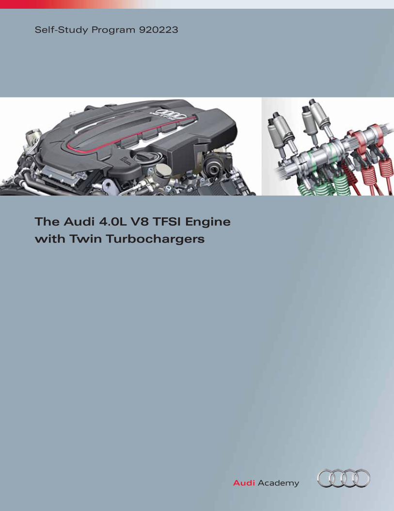
Introduction
1
607_006
The Audi family of V engines has been expanded.
The new 4.0-liter V8 TFSI engine is the fi rst 8-cylinder
gasoline engine with twin turbocharging and FSI
technology. Based on the 4.2L V8 FSI normally
aspirated engine of the 2012 Audi A8, capacity was
modifi ed to further enhance fuel effi ciency.
Additional fuel savings have been realized through
cylinder deactivation. By deactivating four cylinders
in various load and operating conditions, the engine
uses less fuel.
Limited space in the engine compartment was
overcome by mounting both turbochargers and the
charge air cooler in the inner V of the engine. Referred
to as an HSI (Hot Side In) arrangement, special
monitoring ensures that under hood temperatures are
kept within a safe and effi cient range.
The broad performance spectrum of this engine is
intended for use in other Audi models and other
brands in the VW Group.
The 4.0L V8 TFSI engine uses Audi modular effi ciency
technologies, for example, in the design of the
recuperation system and in friction reduction. High-
end technologies, such as plate honing, are employed
during manufacturing at the Audi factory in Györ,
Hungary.
In this Self-Study Program you will become familiar
with the technology of the 4.0L V8 TFSI. When
completed, you will be able to answer the following
questions:
• What are the basic design features of the engine?
• How do various engine systems operate, such as,
air supply, oil supply, cooling?
• What is the effect of cylinder deactivation and
how is it implemented?
• What are the special features of the second
generation ITM system?
• What has changed in the engine management
system when compared with the 4.2L V8 FSI
engine?
• What are some of the special procedures that must
be followed during service and repair work?
2
Eight Cylinder Engines at Audi
Powerful eight-cylinder engines have long been a part
of Audi’s product portfolio. They refl ect the brand’s
premium status in the high performance and luxury
sport sedan marketplace. V8 engines are optional
equipment in Audi sports cars and SUVs as well.
The origins of eight-cylinder engines under the
Four Rings logo go back to the Horch nameplate, an
early brand within the Auto Union which would later
become Audi AG.
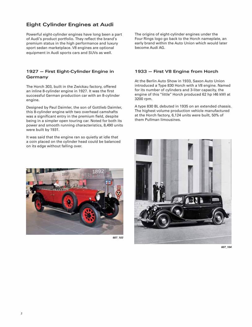
1927 — First Eight-Cylinder Engine in Germany
The Horch 303, built in the Zwickau factory, offered
an inline 8-cylinder engine in 1927. It was the fi rst
successful German production car with an 8-cylinder
engine.
Designed by Paul Daimler, the son of Gottlieb Daimler,
this 8-cylinder engine with two overhead camshafts
was a signifi cant entry in the premium fi eld, despite
being in a simpler open touring car. Noted for both its
power and smooth running characteristics, 8,490 units
were built by 1931.
It was said that the engine ran so quietly at idle that
a coin placed on the cylinder head could be balanced
on its edge without falling over.
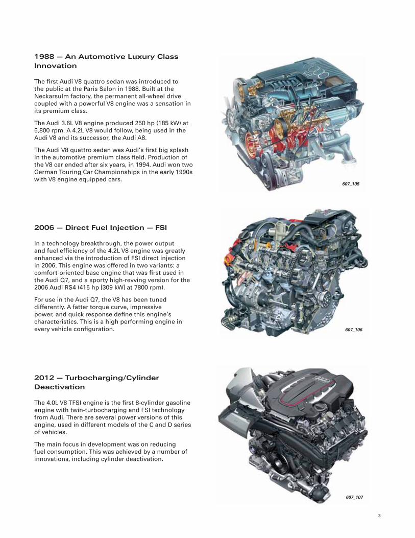
1933 — First V8 Engine from Horch
At the Berlin Auto Show in 1933, Saxon Auto Union
introduced a Type 830 Horch with a V8 engine. Named
for its number of cylinders and 3-liter capacity, the
engine of this “little” Horch produced 62 hp (46 kW) at
3200 rpm.
A type 830 BL debuted in 1935 on an extended chassis.
The highest volume production vehicle manufactured
at the Horch factory, 6,124 units were built, 50% of
them Pullman limousines.
607_104
607_103
3
1988 — An Automotive Luxury Class Innovation
The fi rst Audi V8 quattro sedan was introduced to
the public at the Paris Salon in 1988. Built at the
Neckarsulm factory, the permanent all-wheel drive
coupled with a powerful V8 engine was a sensation in
its premium class.
The Audi 3.6L V8 engine produced 250 hp (185 kW) at
5,800 rpm. A 4.2L V8 would follow, being used in the
Audi V8 and its successor, the Audi A8.
The Audi V8 quattro sedan was Audi’s fi rst big splash
in the automotive premium class fi eld. Production of
the V8 car ended after six years, in 1994. Audi won two
German Touring Car Championships in the early 1990s
with V8 engine equipped cars.
2006 — Direct Fuel Injection — FSI
In a technology breakthrough, the power output
and fuel effi ciency of the 4.2L V8 engine was greatly
enhanced via the introduction of FSI direct injection
in 2006. This engine was offered in two variants: a
comfort-oriented base engine that was fi rst used in
the Audi Q7, and a sporty high-revving version for the
2006 Audi RS4 (415 hp [309 kW] at 7800 rpm).
For use in the Audi Q7, the V8 has been tuned
differently. A fatter torque curve, impressive
power, and quick response defi ne this engine’s
characteristics. This is a high performing engine in
every vehicle confi guration.
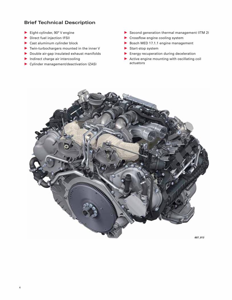
2012 — Turbocharging/Cylinder Deactivation
The 4.0L V8 TFSI engine is the fi rst 8-cylinder gasoline
engine with twin-turbocharging and FSI technology
from Audi. There are several power versions of this
engine, used in different models of the C and D series
of vehicles.
The main focus in development was on reducing
fuel consumption. This was achieved by a number of
innovations, including cylinder deactivation.
607_105
607_106
607_107
4
Brief Technical Description
• Eight-cylinder, 90° V engine
• Direct fuel injection (FSI)
• Cast aluminum cylinder block
• Twin-turbochargers mounted in the inner V
• Double air-gap insulated exhaust manifolds
• Indirect charge air intercooling
• Cylinder management/deactivation (ZAS)
• Second generation thermal management (ITM 2)
• Crossfl ow engine cooling system
• Bosch MED 17.1.1 engine management
• Start-stop system
• Energy recuperation during deceleration
• Active engine mounting with oscillating coil
actuators
607_013
5
Variants
The 4.0L V8 TFSI engine is used in various Audi
models. Depending on vehicle series and in which
markets the vehicles are available, the engines have
different features.
The table below contains information about variants
and versions or adaptations. You can fi nd additional
technical data on the following pages.
1 Illustration shows S6 engine2 Illustration shows S8 engine
NoteThe technical descriptions in this Self-Study Program are based on engines available in the Audi S6 and
Audi S7 (C7 series). Differences in other engine variants will be pointed out separately in the individual
component group descriptions. !
Series
Vehicle use Audi A8 Audi S8Audi S6
Audi S7
C71 D42
Engine code CEUA CGTACEUC
Power 420 hp (309 kW) 520 hp (382 kW)420 hp (309 kW)
Torque 443 lb ft (600 Nm) 479 lb ft (650 Nm)406 lb ft (550 Nm)
Engine weight 483 lb (219 kg) 494 lb (224 kg)483 lb (219 kg)
Transmission AL551-8Q AL551-8QDL511-7Q
6
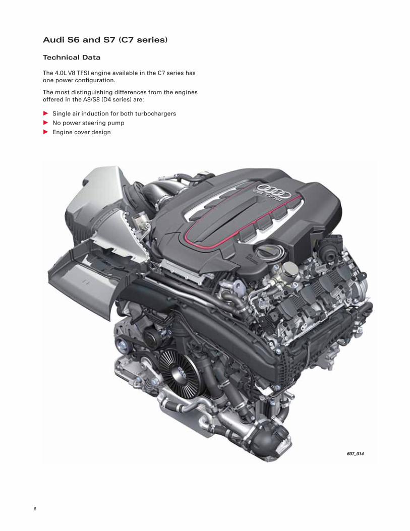
Audi S6 and S7 (C7 series)
Technical Data
The 4.0L V8 TFSI engine available in the C7 series has
one power confi guration.
The most distinguishing differences from the engines
offered in the A8/S8 (D4 series) are:
• Single air induction for both turbochargers
• No power steering pump
• Engine cover design
607_014
7
Power in hp (kW)
Torque in lb ft (Nm)
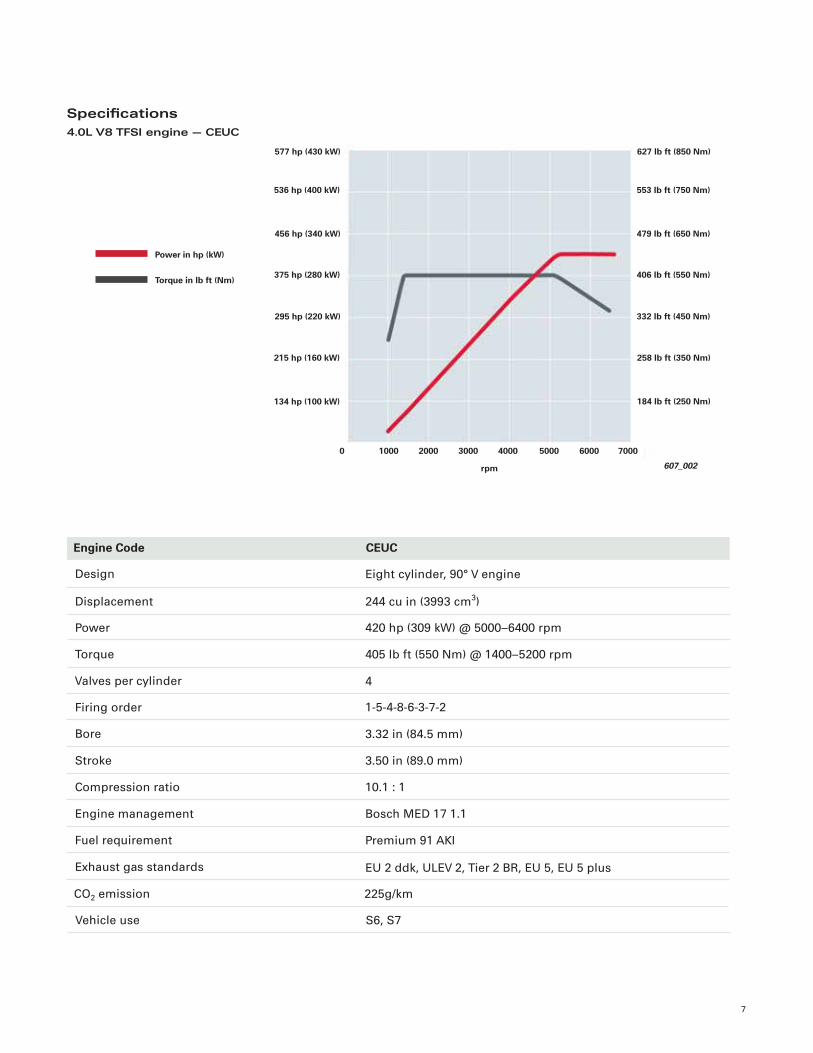
Specifi cations4.0L V8 TFSI engine — CEUC
Design
Displacement
Power
Torque
Valves per cylinder
Firing order
Bore
Stroke
Compression ratio
Eight cylinder, 90° V engine
244 cu in (3993 cm3)
420 hp (309 kW) @ 5000–6400 rpm
405 lb ft (550 Nm) @ 1400–5200 rpm
4
1-5-4-8-6-3-7-2
3.32 in (84.5 mm)
3.50 in (89.0 mm)
10.1 : 1
Engine Code CEUC
Engine management
Fuel requirement
Exhaust gas standards
Bosch MED 17 1.1
Premium 91 AKI
EU 2 ddk, ULEV 2, Tier 2 BR, EU 5, EU 5 plus
CO2 emission 225g/km
Vehicle use S6, S7
607_002
536 hp (400 kW)
456 hp (340 kW)
375 hp (280 kW)
295 hp (220 kW)
577 hp (430 kW)
215 hp (160 kW)
0
134 hp (100 kW)
553 lb ft (750 Nm)
479 lb ft (650 Nm)
406 lb ft (550 Nm)
332 lb ft (450 Nm)
627 lb ft (850 Nm)
258 lb ft (350 Nm)
184 lb ft (250 Nm)
2000 3000 4000 70001000 60005000
rpm
8
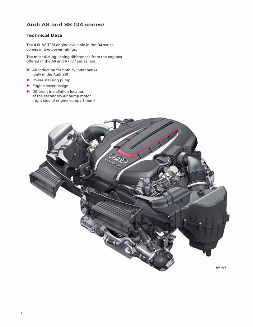
Audi A8 and S8 (D4 series)
Technical Data
The 4.0L V8 TFSI engine available in the D4 series
comes in two power ratings.
The most distinguishing differences from the engines
offered in the A6 and A7 (C7 series) are:
• Air induction for both cylinder banks
(only in the Audi S8)
• Power steering pump
• Engine cover design
• Different installation location
of the secondary air pump motor
(right side of engine compartment)
607_007
9
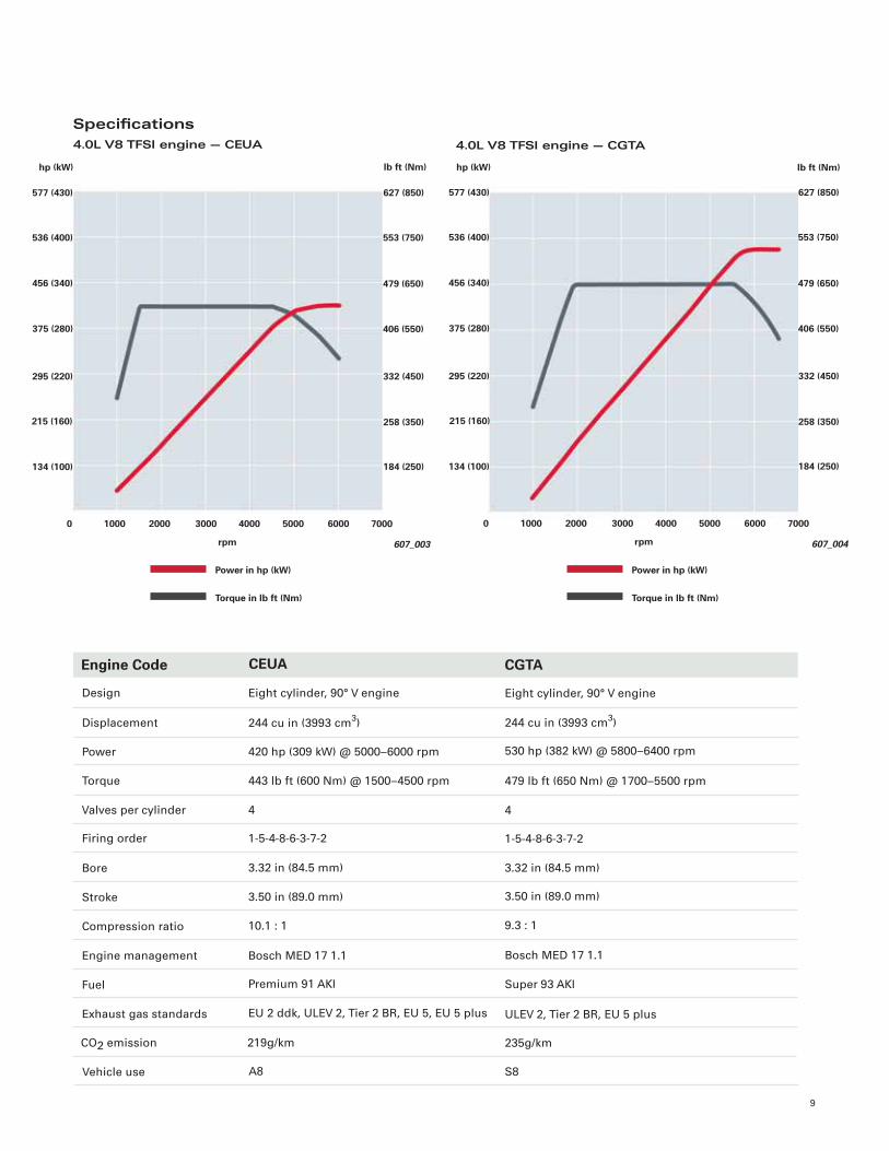
Specifi cations4.0L V8 TFSI engine — CEUA
Power in hp (kW)
Torque in lb ft (Nm)
Design
Displacement
Power
Torque
Valves per cylinder
Firing order
Bore
Stroke
Compression ratio
Eight cylinder, 90° V engine
244 cu in (3993 cm3)
420 hp (309 kW) @ 5000–6000 rpm
443 lb ft (600 Nm) @ 1500–4500 rpm
4
1-5-4-8-6-3-7-2
3.32 in (84.5 mm)
3.50 in (89.0 mm)
10.1 : 1
Engine Code
Engine management
Fuel
Exhaust gas standards
Bosch MED 17 1.1
Premium 91 AKI
EU 2 ddk, ULEV 2, Tier 2 BR, EU 5, EU 5 plus
CO2 emission 219g/km
Vehicle use A8
CEUA CGTA
Eight cylinder, 90° V engine
244 cu in (3993 cm3)
530 hp (382 kW) @ 5800–6400 rpm
479 lb ft (650 Nm) @ 1700–5500 rpm
4
1-5-4-8-6-3-7-2
3.32 in (84.5 mm)
3.50 in (89.0 mm)
9.3 : 1
Bosch MED 17 1.1
Super 93 AKI
ULEV 2, Tier 2 BR, EU 5 plus
235g/km
S8
4.0L V8 TFSI engine — CGTA
536 (400)
456 (340)
375 (280)
295 (220)
577 (430)
215 (160)
0
134 (100)
553 (750)
479 (650)
406 (550)
332 (450)
627 (850)
258 (350)
184 (250)
2000 3000 4000 60001000 5000 7000
rpm 607_003
Power in hp (kW)
Torque in lb ft (Nm)
536 (400)
456 (340)
375 (280)
295 (220)
577 (430)
215 (160)
0
134 (100)
553 (750)
479 (650)
406 (550)
332 (450)
627 (850)
258 (350)
184 (250)
2000 3000 4000 60001000 5000 7000
rpm 607_004
lb ft (Nm) hp (kW)hp (kW) lb ft (Nm)
Engine Mechanical
10
Switchable piston cooling jets
Cylinder block
Upper part of oil pan
Oil supply module cover with connections for the oil supply
Bed plate
Windage tray
607_024
Lower part of oil pan
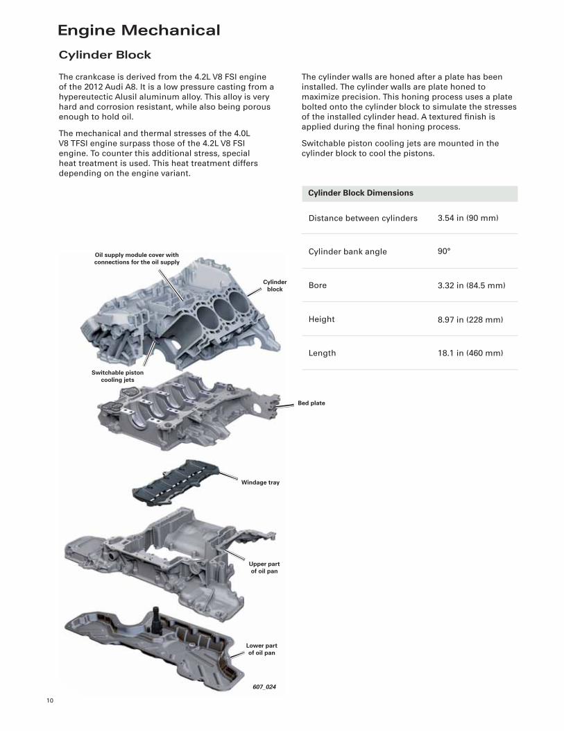
Cylinder Block
The crankcase is derived from the 4.2L V8 FSI engine
of the 2012 Audi A8. It is a low pressure casting from a
hypereutectic Alusil aluminum alloy. This alloy is very
hard and corrosion resistant, while also being porous
enough to hold oil.
The mechanical and thermal stresses of the 4.0L
V8 TFSI engine surpass those of the 4.2L V8 FSI
engine. To counter this additional stress, special
heat treatment is used. This heat treatment differs
depending on the engine variant.
Cylinder Block Dimensions
Distance between cylinders
Cylinder bank angle
Bore
Height
Length
3.54 in (90 mm)
90°
3.32 in (84.5 mm)
8.97 in (228 mm)
18.1 in (460 mm)
The cylinder walls are honed after a plate has been
installed. The cylinder walls are plate honed to
maximize precision. This honing process uses a plate
bolted onto the cylinder block to simulate the stresses
of the installed cylinder head. A textured fi nish is
applied during the fi nal honing process.
Switchable piston cooling jets are mounted in the
cylinder block to cool the pistons.
11
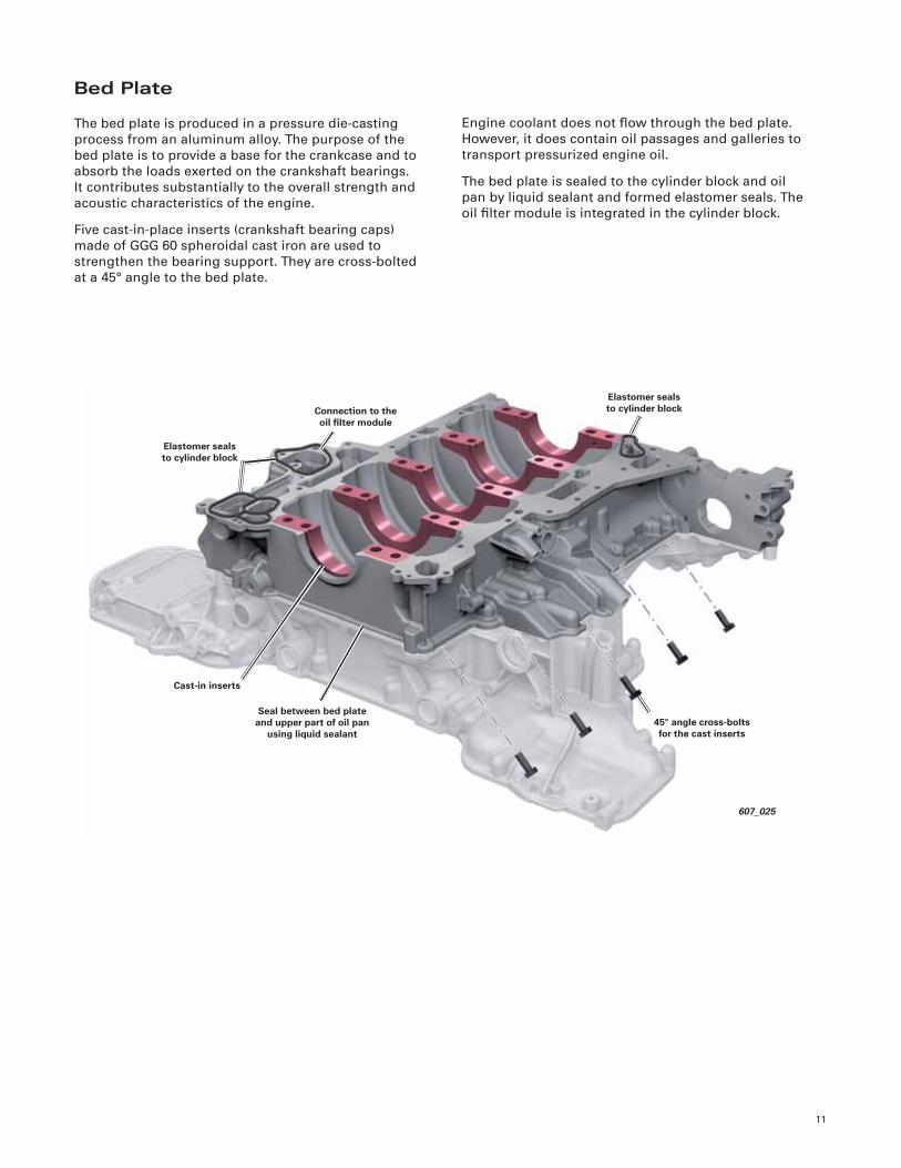
Bed Plate
The bed plate is produced in a pressure die-casting
process from an aluminum alloy. The purpose of the
bed plate is to provide a base for the crankcase and to
absorb the loads exerted on the crankshaft bearings.
It contributes substantially to the overall strength and
acoustic characteristics of the engine.
Five cast-in-place inserts (crankshaft bearing caps)
made of GGG 60 spheroidal cast iron are used to
strengthen the bearing support. They are cross-bolted
at a 45° angle to the bed plate.
Engine coolant does not fl ow through the bed plate.
However, it does contain oil passages and galleries to
transport pressurized engine oil.
The bed plate is sealed to the cylinder block and oil
pan by liquid sealant and formed elastomer seals. The
oil fi lter module is integrated in the cylinder block.
45° angle cross-bolts for the cast inserts
Elastomer seals to cylinder blockConnection to the
oil fi lter module
Elastomer seals to cylinder block
607_025
Cast-in inserts
Seal between bed plate and upper part of oil pan
using liquid sealant
12
607_027
Plastic windage tray
Return to the oil pan
607_026
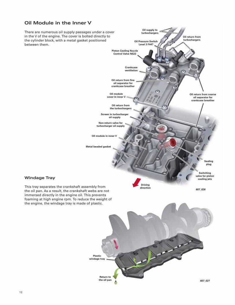
Oil return from the turbochargers
Piston Cooling Nozzle Control Valve N522
Screen in turbocharger oil supply
Oil supply to turbochargers
Crankcase ventilation
Oil return from turbochargers
Oil return from fi ne oil separator for
crankcase breather
Oil Pressure Switch Level 3 F447
Oil return from coarse oil separator for
crankcase breather
Oil module cover in inner V
Driving direction
Switching valve for piston
cooling jets
Sealing plug
Oil module in inner V
Non-return valve for turbocharger oil supply
Metal beaded gasket
Oil Module in the Inner V
There are numerous oil supply passages under a cover
in the V of the engine. The cover is bolted directly to
the cylinder block, with a metal gasket positioned
between them.
Windage Tray
This tray separates the crankshaft assembly from
the oil pan. As a result, the crankshaft webs are not
immersed directly in the engine oil. This prevents
foaming at high engine rpm. To reduce the weight of
the engine, the windage tray is made of plastic.
13
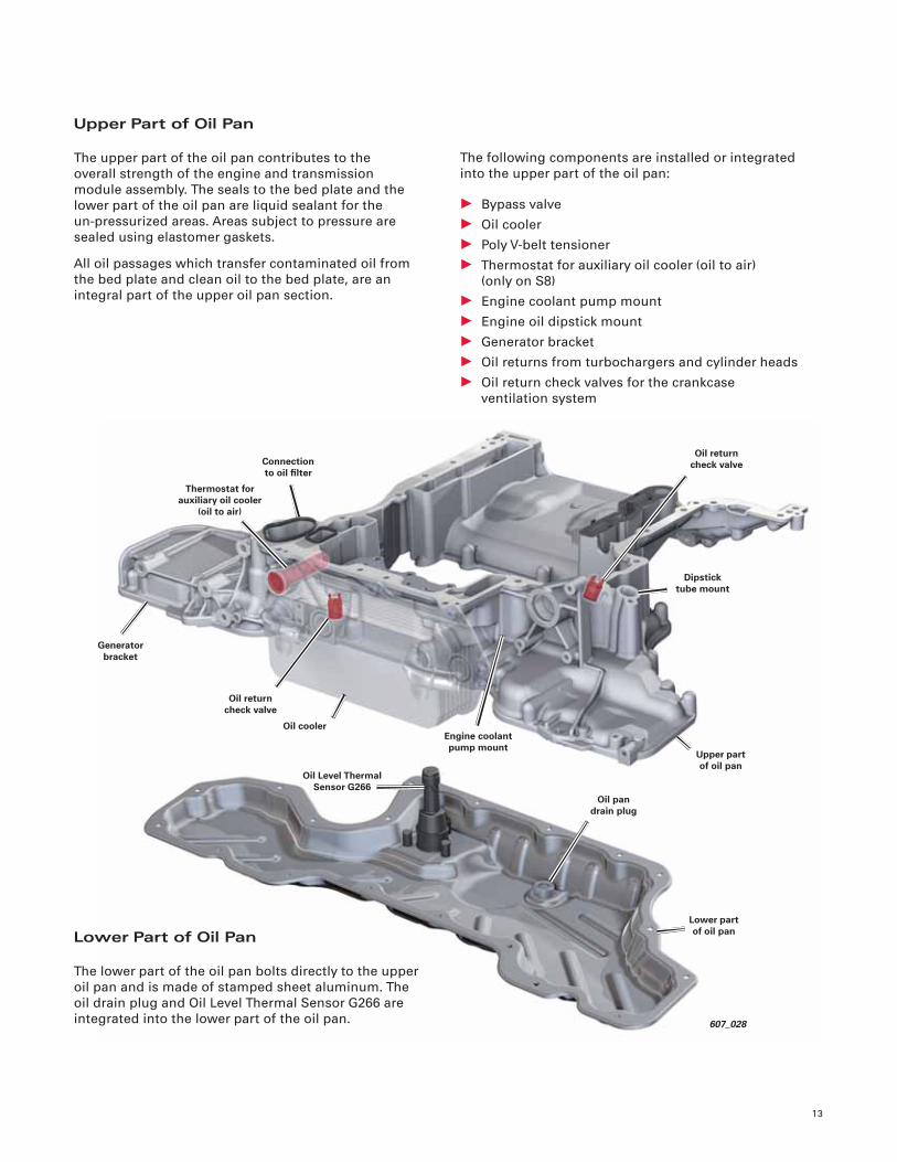
607_028
Upper part of oil pan
Oil return check valve
Oil Level Thermal Sensor G266
Thermostat for auxiliary oil cooler
(oil to air)
Dipstick tube mount
Connection to oil fi lter
Oil return check valve
Oil cooler
Oil pan drain plug
Lower part of oil pan
Upper Part of Oil Pan
The upper part of the oil pan contributes to the
overall strength of the engine and transmission
module assembly. The seals to the bed plate and the
lower part of the oil pan are liquid sealant for the
un-pressurized areas. Areas subject to pressure are
sealed using elastomer gaskets.
All oil passages which transfer contaminated oil from
the bed plate and clean oil to the bed plate, are an
integral part of the upper oil pan section.
Lower Part of Oil Pan
The lower part of the oil pan bolts directly to the upper
oil pan and is made of stamped sheet aluminum. The
oil drain plug and Oil Level Thermal Sensor G266 are
integrated into the lower part of the oil pan.
The following components are installed or integrated
into the upper part of the oil pan:
• Bypass valve
• Oil cooler
• Poly V-belt tensioner
• Thermostat for auxiliary oil cooler (oil to air)
(only on S8)
• Engine coolant pump mount
• Engine oil dipstick mount
• Generator bracket
• Oil returns from turbochargers and cylinder heads
• Oil return check valves for the crankcase
ventilation system
Generator bracket
Engine coolant pump mount
14
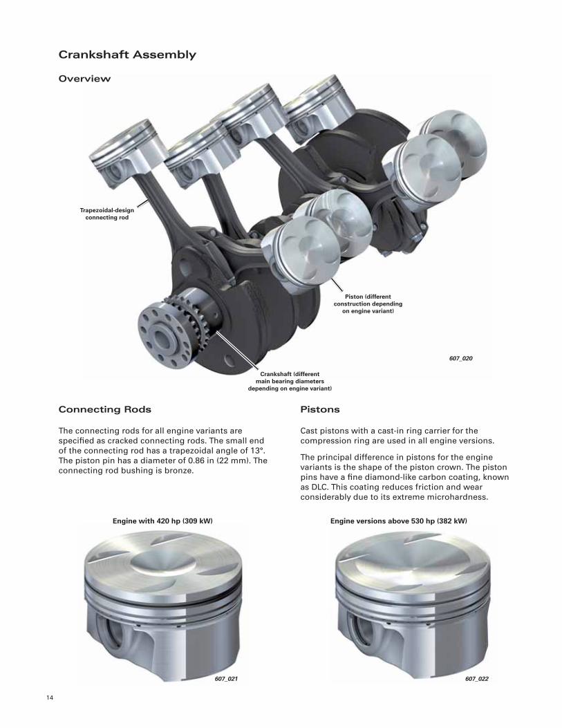
607_020
Piston (different construction depending
on engine variant)
Trapezoidal-design connecting rod
Crankshaft (different main bearing diameters
depending on engine variant)
Crankshaft Assembly
Overview
Connecting Rods
The connecting rods for all engine variants are
specifi ed as cracked connecting rods. The small end
of the connecting rod has a trapezoidal angle of 13°.
The piston pin has a diameter of 0.86 in (22 mm). The
connecting rod bushing is bronze.
Pistons
Cast pistons with a cast-in ring carrier for the
compression ring are used in all engine versions.
The principal difference in pistons for the engine
variants is the shape of the piston crown. The piston
pins have a fi ne diamond-like carbon coating, known
as DLC. This coating reduces friction and wear
considerably due to its extreme microhardness.
607_021
Engine with 420 hp (309 kW) Engine versions above 530 hp (382 kW)
607_022
15
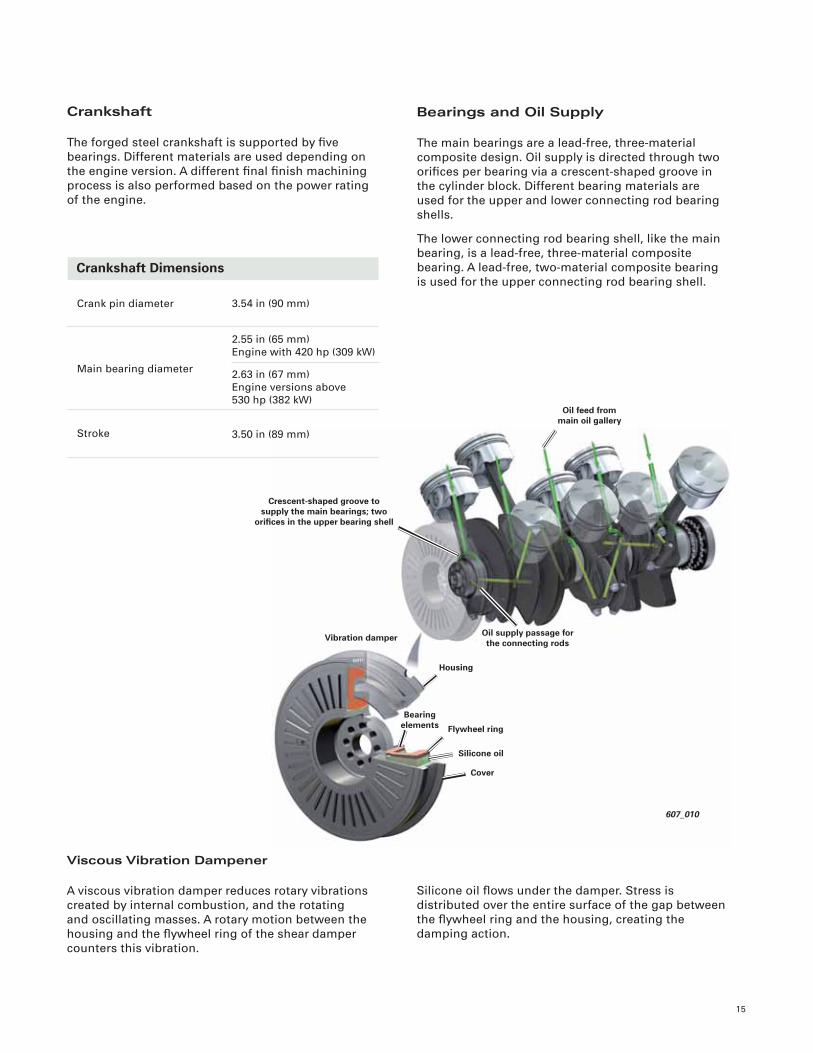
607_010
Housing
Oil feed from main oil gallery
Bearing elements
Oil supply passage for the connecting rods
Crescent-shaped groove to supply the main bearings; two
orifi ces in the upper bearing shell
Vibration damper
Flywheel ring
Silicone oil
Cover
Crankshaft
The forged steel crankshaft is supported by fi ve
bearings. Different materials are used depending on
the engine version. A different fi nal fi nish machining
process is also performed based on the power rating
of the engine.
Bearings and Oil Supply
The main bearings are a lead-free, three-material
composite design. Oil supply is directed through two
orifi ces per bearing via a crescent-shaped groove in
the cylinder block. Different bearing materials are
used for the upper and lower connecting rod bearing
shells.
The lower connecting rod bearing shell, like the main
bearing, is a lead-free, three-material composite
bearing. A lead-free, two-material composite bearing
is used for the upper connecting rod bearing shell. Crankshaft Dimensions
Crank pin diameter
Main bearing diameter
Stroke
3.54 in (90 mm)
2.55 in (65 mm)
Engine with 420 hp (309 kW)
3.50 in (89 mm)
2.63 in (67 mm)
Engine versions above
530 hp (382 kW)
Viscous Vibration Dampener
A viscous vibration damper reduces rotary vibrations
created by internal combustion, and the rotating
and oscillating masses. A rotary motion between the
housing and the fl ywheel ring of the shear damper
counters this vibration.
Silicone oil fl ows under the damper. Stress is
distributed over the entire surface of the gap between
the fl ywheel ring and the housing, creating the
damping action.
16
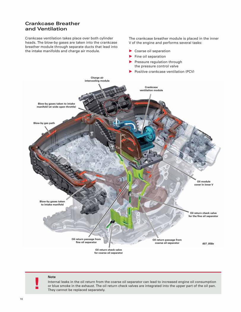
607_058a
Crankcase ventilation module
Blow-by gas path
Oil return passage from fi ne oil separator
Charge air intercooling module
Blow-by gases taken to intake manifold (at wide open throttle)
Blow-by gases taken to intake manifold
Oil return check valve for coarse oil separator
Oil return passage from coarse oil separator
Oil module cover in inner V
Oil return check valve for the fi ne oil separator
Crankcase Breatherand Ventilation
Crankcase ventilation takes place over both cylinder
heads. The blow-by gases are taken into the crankcase
breather module through separate ducts that lead into
the intake manifolds and charge air module.
The crankcase breather module is placed in the inner
V of the engine and performs several tasks:
• Coarse oil separation
• Fine oil separation
• Pressure regulation through
the pressure control valve
• Positive crankcase ventilation (PCV)
NoteInternal leaks in the oil return from the coarse oil separator can lead to increased engine oil consumption
or blue smoke in the exhaust. The oil return check valves are integrated into the upper part of the oil pan.
They cannot be replaced separately.!
17
607_120
Oil return into the oil pan
Oil return from the coarse or fi ne oil separator
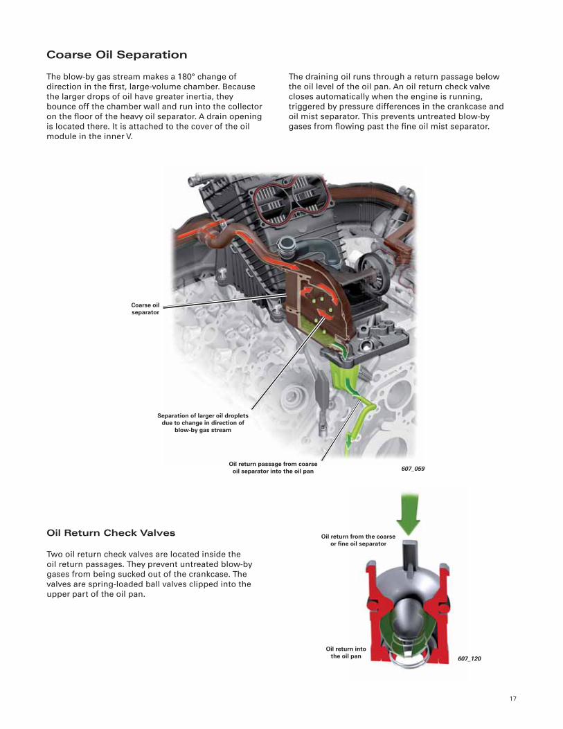
Coarse Oil Separation
The blow-by gas stream makes a 180° change of
direction in the fi rst, large-volume chamber. Because
the larger drops of oil have greater inertia, they
bounce off the chamber wall and run into the collector
on the fl oor of the heavy oil separator. A drain opening
is located there. It is attached to the cover of the oil
module in the inner V.
The draining oil runs through a return passage below
the oil level of the oil pan. An oil return check valve
closes automatically when the engine is running,
triggered by pressure differences in the crankcase and
oil mist separator. This prevents untreated blow-by
gases from fl owing past the fi ne oil mist separator.
Oil Return Check Valves
Two oil return check valves are located inside the
oil return passages. They prevent untreated blow-by
gases from being sucked out of the crankcase. The
valves are spring-loaded ball valves clipped into the
upper part of the oil pan.
607_059Oil return passage from coarse
oil separator into the oil pan
Coarse oil separator
Separation of larger oil droplets due to change in direction of
blow-by gas stream
18
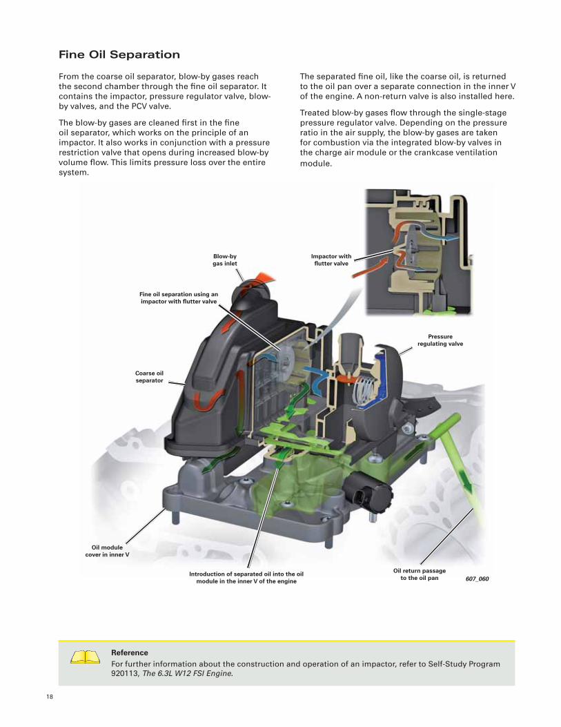
Fine Oil Separation
From the coarse oil separator, blow-by gases reach
the second chamber through the fi ne oil separator. It
contains the impactor, pressure regulator valve, blow-
by valves, and the PCV valve.
The blow-by gases are cleaned fi rst in the fi ne
oil separator, which works on the principle of an
impactor. It also works in conjunction with a pressure
restriction valve that opens during increased blow-by
volume fl ow. This limits pressure loss over the entire
system.
The separated fi ne oil, like the coarse oil, is returned
to the oil pan over a separate connection in the inner V
of the engine. A non-return valve is also installed here.
Treated blow-by gases fl ow through the single-stage
pressure regulator valve. Depending on the pressure
ratio in the air supply, the blow-by gases are taken
for combustion via the integrated blow-by valves in
the charge air module or the crankcase ventilation
module.
ReferenceFor further information about the construction and operation of an impactor, refer to Self-Study Program
920113, The 6.3L W12 FSI Engine.
607_060
Coarse oil separator
Impactor with fl utter valve
Pressure regulating valve
Blow-by gas inlet
Fine oil separation using an impactor with fl utter valve
Oil return passage to the oil pan
Introduction of separated oil into the oil module in the inner V of the engine
Oil module cover in inner V
19
607_062
Intake air to the turbochargersConnecting pipe to
introduce blow-by gases
Intake air from air fi lter
607_061
Charge air cooling module
Introduction of blow-by gases at
idle and part throttle
Blow-by valve (open)
Crankcase ventilation
modulePressure
regulation valve
Blow-by valve
(closed)
Cleansed blow-by gases from coarse and
fi ne oil separators
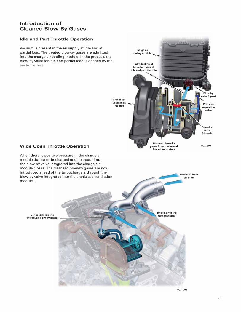
Introduction ofCleaned Blow-By Gases
Idle and Part Throttle Operation
Vacuum is present in the air supply at idle and at
partial load. The treated blow-by gases are admitted
into the charge air cooling module. In the process, the
blow-by valve for idle and partial load is opened by the
suction effect.
Wide Open Throttle Operation
When there is positive pressure in the charge air
module during turbocharged engine operation,
the blow-by valve integrated into the charge air
module closes. The cleansed blow-by gases are now
introduced ahead of the turbochargers through the
blow-by valve integrated into the crankcase ventilation
module.
20
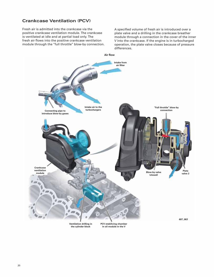
Crankcase Ventilation (PCV)
Fresh air is admitted into the crankcase via the
positive crankcase ventilation module. The crankcase
is ventilated at idle and at partial load only. The
fresh air fl ows into the positive crankcase ventilation
module through the “full throttle” blow-by connection.
A specifi ed volume of fresh air is introduced over a
plate valve and a drilling in the crankcase breather
module through a connection in the cover of the inner
V into the crankcase. If the engine is in turbocharged
operation, the plate valve closes because of pressure
differences.
607_063
PCV stabilizing chamber in oil module in the V
Intake from air fi lter
Crankcase ventilation
module
Intake air to the turbochargers
“Full throttle” blow-by connection
Air fl ow
Connecting pipe to introduce blow-by gases
Ventilation drilling in the cylinder block
Blow-by valve (closed)
Plate valve 2
21
607_121
Vacuum actuator for intake
manifold fl aps
Non-return valve
Introduction of fuel vapors into the charge air
intercooling module
Vacuum actuator for intake manifold fl aps
Intake Manifold Runner Control
Valve N316
EVAP Canister Purge Regulator
Valve 1 N80
Activated charcoal canister
on fuel tank
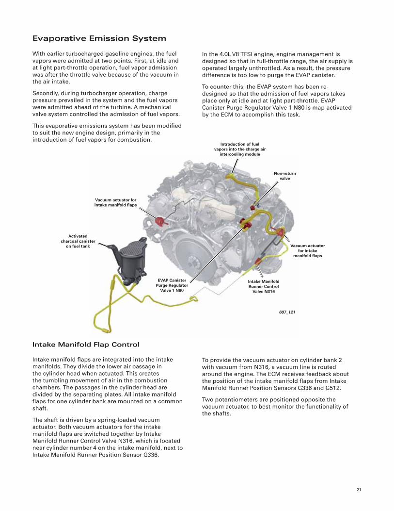
Evaporative Emission System
With earlier turbocharged gasoline engines, the fuel
vapors were admitted at two points. First, at idle and
at light part-throttle operation, fuel vapor admission
was after the throttle valve because of the vacuum in
the air intake.
Secondly, during turbocharger operation, charge
pressure prevailed in the system and the fuel vapors
were admitted ahead of the turbine. A mechanical
valve system controlled the admission of fuel vapors.
This evaporative emissions system has been modifi ed
to suit the new engine design, primarily in the
introduction of fuel vapors for combustion.
In the 4.0L V8 TFSI engine, engine management is
designed so that in full-throttle range, the air supply is
operated largely unthrottled. As a result, the pressure
difference is too low to purge the EVAP canister.
To counter this, the EVAP system has been re-
designed so that the admission of fuel vapors takes
place only at idle and at light part-throttle. EVAP
Canister Purge Regulator Valve 1 N80 is map-activated
by the ECM to accomplish this task.
Intake Manifold Flap Control
Intake manifold fl aps are integrated into the intake
manifolds. They divide the lower air passage in
the cylinder head when actuated. This creates
the tumbling movement of air in the combustion
chambers. The passages in the cylinder head are
divided by the separating plates. All intake manifold
fl aps for one cylinder bank are mounted on a common
shaft.
The shaft is driven by a spring-loaded vacuum
actuator. Both vacuum actuators for the intake
manifold fl aps are switched together by Intake
Manifold Runner Control Valve N316, which is located
near cylinder number 4 on the intake manifold, next to
Intake Manifold Runner Position Sensor G336.
To provide the vacuum actuator on cylinder bank 2
with vacuum from N316, a vacuum line is routed
around the engine. The ECM receives feedback about
the position of the intake manifold fl aps from Intake
Manifold Runner Position Sensors G336 and G512.
Two potentiometers are positioned opposite the
vacuum actuator, to best monitor the functionality of
the shafts.
22
• Intake passages with dividing plates
• Spark plugs centrally located (in the middle of the
four inclined valves)
• Fuel injectors located to the side
• High pressure fuel pumps driven by the exhaust
camshafts (triple lobes)
• Mechanical vacuum pump driven by the intake
camshaft
• Non-return valves prevent engine oil from running
back (running the pressure passages empty)
• Oil screen to protect against contamination
Cylinder Heads
The cylinder heads for the 4.0L V8 TFSI engine have
been redesigned. The design challenge was to remedy
the higher mechanical and thermal requirements
compared to the cylinder heads of the 4.2L V8 FSI
engines.
The cylinder heads for all performance versions of
the engine are laid out identically. The only difference
consists in different valve timing (lift event lengths for
the camshafts) in the engine variants with more than
420 hp (309 kW).
The most signifi cant design change is the reversed
arrangement of intake and exhaust sides, Hot Side
In (HSI) of the cylinder head. This layout enables
compact construction, improved thermodynamics,
and short gas fl ow paths with minimal fl ow losses.
The 4.0L V8 TFSI engine responds crisply to throttle
pedal inputs. Extensive insulation of hot components,
particularly the exhaust manifolds, keeps thermal
conditions in the inner V of the engine stable.
The fresh air intake system is placed on the outside of
the cylinder banks.
Switchable fl aps in the intake passages cause a rolling
rotation of incoming air. The intensive tumbling
action of the fuel-air mixture cools the combustion
chambers, which allows a high compression ratio
(even with turbocharging) with no tendency to knock.
Technical Features
• Aluminum cylinder head with two camshafts
• Four-valve technology
• Cylinder head covers with a ladder frame
• Camshaft phasing on the intake and exhaust side
• Hall sensors monitor the position of each
camshaft
• Crossfl ow cooling
• Coolant passage between intake and exhaust
valves cooled
• Cylinder deactivation through AVS
• Triple-layer cylinder head gasket
• Sealing of cylinder head covers using liquid
sealant
Valve Train
The valves are actuated by roller cam followers. They
have a different geometry to allow for cylinder on
demand. The roller cam followers with wide rollers are
assigned to the cylinders without cylinder on demand.
The roller cam followers with narrow rollers are
assigned to the cylinders with cylinder on demand.
Additional features:
• Hydraulic valve lash compensation
• Exhaust valves with hardened seats, sodium fi lled
for cooling
• Solid stem intake valves with hardened seats
• Sintered lead steel exhaust valve guides
• Bronze intake valve guides
• Single valve springs operating at relative low
tension
• Valve lift: 11 mm
Camshaft Adjustment
Both intake and exhaust camshafts are continuously
adjustable. The range of adjustment is 42° of
crankshaft angle for all. The position of each camshaft
is monitored by a Hall sensor. After the engine is
switched OFF, the oil pressure drops and the camshaft
adjusters are locked by a spring actuated locking pin.
Internal exhaust gas recirculation is accomplished
through camshaft timing adjustment (valve overlap).
Exhaust gases are recirculated during 8-cylinder and
4-cylinder mode operations.
23
479_005
607_029
1
2
3
4
5
6
7
9
8
10
111213
14
16
15
21
22
18
17
19
20
23
Driving direction
ConstructionLegend:
1 Camshaft adjustment actuator
2 Camshaft Position Sensor G40
3 High pressure fuel pump
4 Camshaft Adjustment Valve 1 N205
5 Exhaust Camshaft Adjustment Valve 1 N318
6 Camshaft Position Sensor 2 G163
7 Cylinder head cover
8 Inlet camshaft
9 Sliding cam section
10 Roller cam follower
11 Valve spring retainer
12 Valve guide seal
13 Valve keepers
14 Valve spring
15 Intake manifold
16 Non-return valve with connection to vacuum pump
17 Intake Manifold Runner Position Sensor G336
18 Air passage dividers in cylinder head
19 Fuel rail
20 Fuel injectors
21 Exhaust camshaft
22 Exhaust valve
23 Cylinder head 1
24
Chain drives B and C are driven by intermediate gears
and in turn drive the specifi c camshafts for each
cylinder head. Chain drive D provides power to the
accessories.
New special retaining tools T40264/1-3 are needed
to check and adjust camshaft timing. Cylinder head
covers do not need to be removed to locate the
camshafts in correct position.
607_008
Chain drive B
Cylinder bank 1
Spur gear
Chain drive A
Chain drive C
Cylinder bank 2
Chain drive D
Chain Drive
Engine timing is by a chain drive arranged in two
planes with four roller-type chains. The chain drive
assembly is located on the power output side of the
engine, and is hydraulically tensioned. Chain drive A
acts as the distributor drive from the crankshaft to the
intermediate gears.
NoteThe sprockets for the camshaft adjusters are tri-oval sprockets. Always refer to latest technical information
during engine assembly. !
Accessory Drive Gear Module
Chain drive D drives a gear module from which all
accessories are also driven. The only exception is the
generator.
25
Accessory Drive
Generator
The generator is driven is by a fi ve-rib poly-V belt. A
mechanical automatic belt tensioner with a damping
function ensures correct tension.
Additional Accessories
Power is delivered from the crankshaft over chain
drive D, a spur gear drive, a gear module, and drive
shafts.
Power Steering Pump
The power steering pump of the Audi A8 is driven by
the engine. Drive is delivered from the crankshaft over
chain drive D, a spur gear drive, and a gear module.
This drive arrangement for the power steering pump
is not needed in C7 series vehicles because electro-
mechanical steering is used.
Generator
607_009
Belt tensioner
Vibration damper
607_011
Chain drive D
Engine coolant pump
AC compressor
Gear module
Oil pump
Map Controlled Engine Cooling Thermostat F265
Power steering pump
Oil Supply
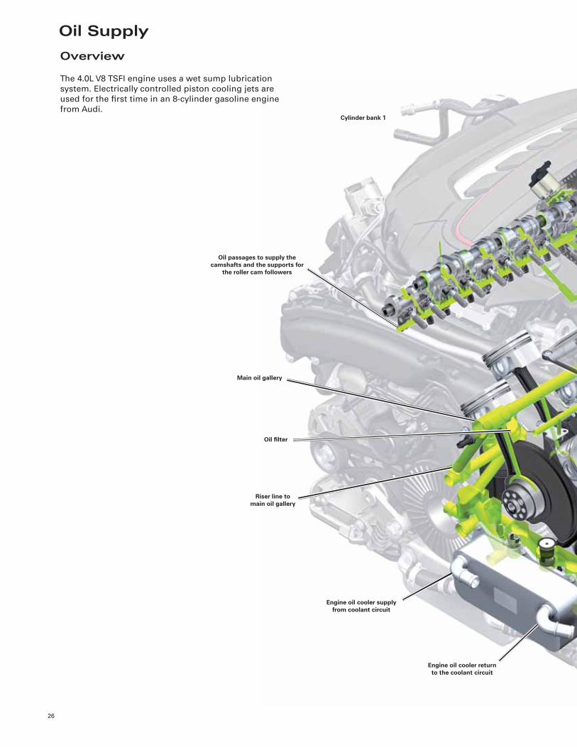
26
Main oil gallery
Oil fi lter
Cylinder bank 1
Oil passages to supply the camshafts and the supports for
the roller cam followers
Riser line to main oil gallery
Engine oil cooler supply from coolant circuit
Engine oil cooler return to the coolant circuit
Overview
The 4.0L V8 TSFI engine uses a wet sump lubrication
system. Electrically controlled piston cooling jets are
used for the fi rst time in an 8-cylinder gasoline engine
from Audi.
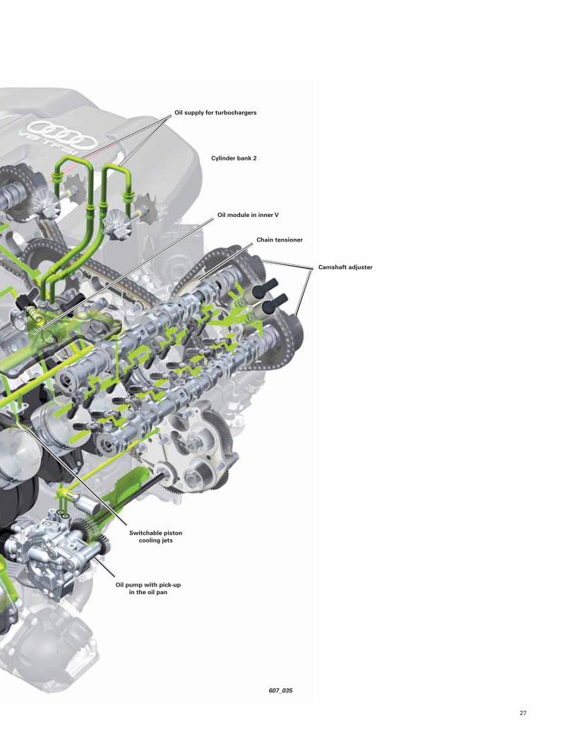
27
607_035
Oil module in inner V
Camshaft adjuster
Switchable piston cooling jets
Oil pump with pick-up in the oil pan
Chain tensioner
Oil supply for turbochargers
Cylinder bank 2
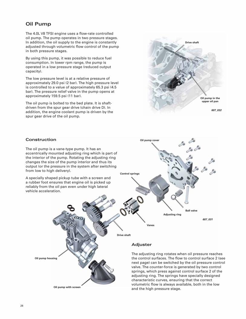
28
607_031
Control springs
Drive shaft
Oil pump cover
Ball valveAdjusting ring
Vanes
Oil pump housing
Oil pump with screen
Oil Pump
The 4.0L V8 TFSI engine uses a fl ow-rate controlled
oil pump. The pump operates in two pressure stages.
In addition, the oil supply to the engine is constantly
adjusted through volumetric fl ow control of the pump
in both pressure stages.
By using this pump, it was possible to reduce fuel
consumption. In lower rpm range, the pump is
operated in a low pressure stage (reduced output
capacity).
The low pressure level is at a relative pressure of
approximately 29.0 psi (2 bar). The high pressure level
is controlled to a value of approximately 65.3 psi (4.5
bar). The pressure relief valve in the pump opens at
approximately 159.5 psi (11 bar).
The oil pump is bolted to the bed plate. It is shaft-
driven from the spur gear drive (chain drive D). In
addition, the engine coolant pump is driven by the
spur gear drive of the oil pump.
Construction
The oil pump is a vane-type pump. It has an
eccentrically mounted adjusting ring which is part of
the interior of the pump. Rotating the adjusting ring
changes the size of the pump interior and thus its
output (or the pressure in the system after switching
from low to high delivery).
A specially shaped pickup tube with a screen and
a rubber foot ensures that engine oil is picked up
reliably from the oil pan even under high lateral
vehicle acceleration.
Adjuster
The adjusting ring rotates when oil pressure reaches
the control surfaces. The fl ow to control surface 2 (see
next page) can be switched by the oil pressure control
valve. The counter-force is generated by two control
springs, which press against control surface 2 of the
adjusting ring. The springs have specially designed
characteristic curves, ensuring that the correct
volumetric fl ow is always available, both in the low
and the high pressure stage.
Drive shaft
Oil pump in the upper oil pan
607_032
29
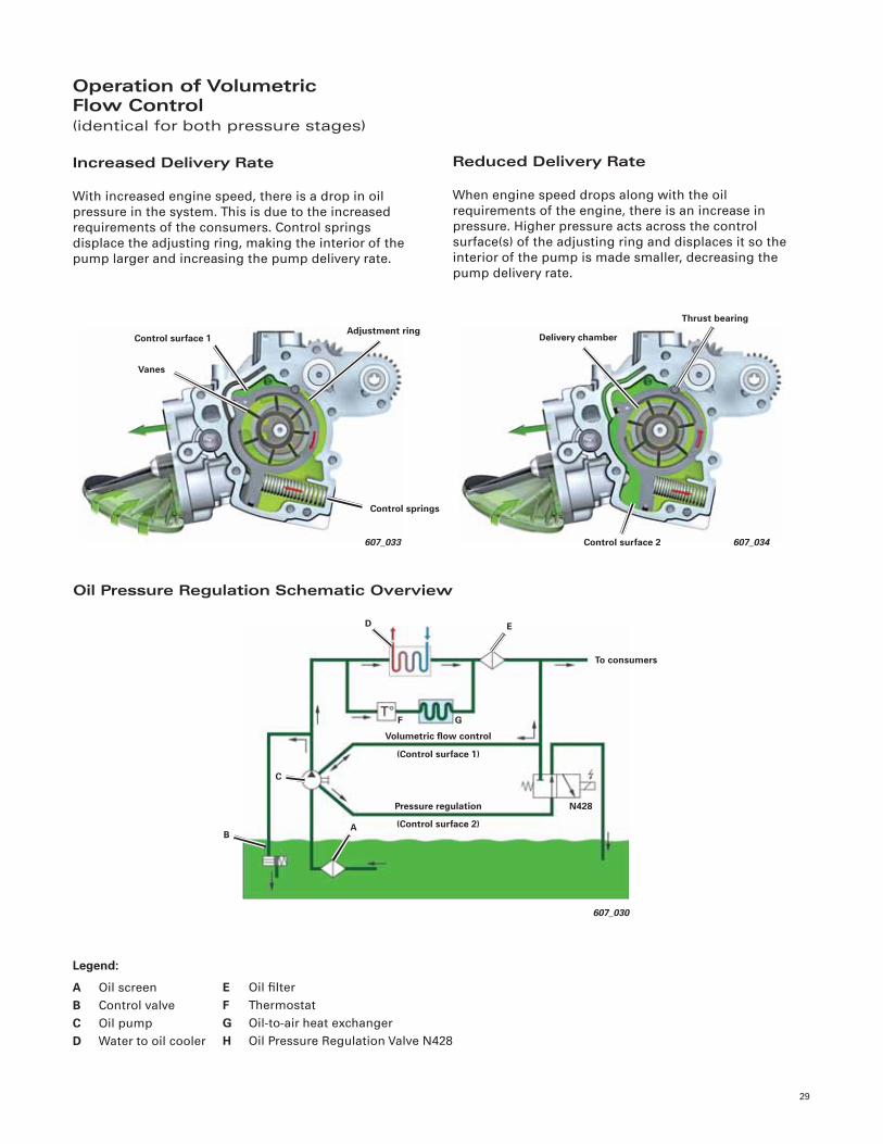
Operation of VolumetricFlow Control(identical for both pressure stages)
Increased Delivery Rate
With increased engine speed, there is a drop in oil
pressure in the system. This is due to the increased
requirements of the consumers. Control springs
displace the adjusting ring, making the interior of the
pump larger and increasing the pump delivery rate.
Reduced Delivery Rate
When engine speed drops along with the oil
requirements of the engine, there is an increase in
pressure. Higher pressure acts across the control
surface(s) of the adjusting ring and displaces it so the
interior of the pump is made smaller, decreasing the
pump delivery rate.
Oil Pressure Regulation Schematic Overview
Legend:
A Oil screen
B Control valve
C Oil pump
D Water to oil cooler
E Oil fi lter
F Thermostat
G Oil-to-air heat exchanger
H Oil Pressure Regulation Valve N428
Control surface 1
607_033
Adjustment ring
Vanes
Control springs
Delivery chamber
607_034
Thrust bearing
Control surface 2
607_030
To consumers
B
ED
Volumetric fl ow control
(Control surface 1)
Pressure regulation
(Control surface 2)
GF
N428
A
C
30
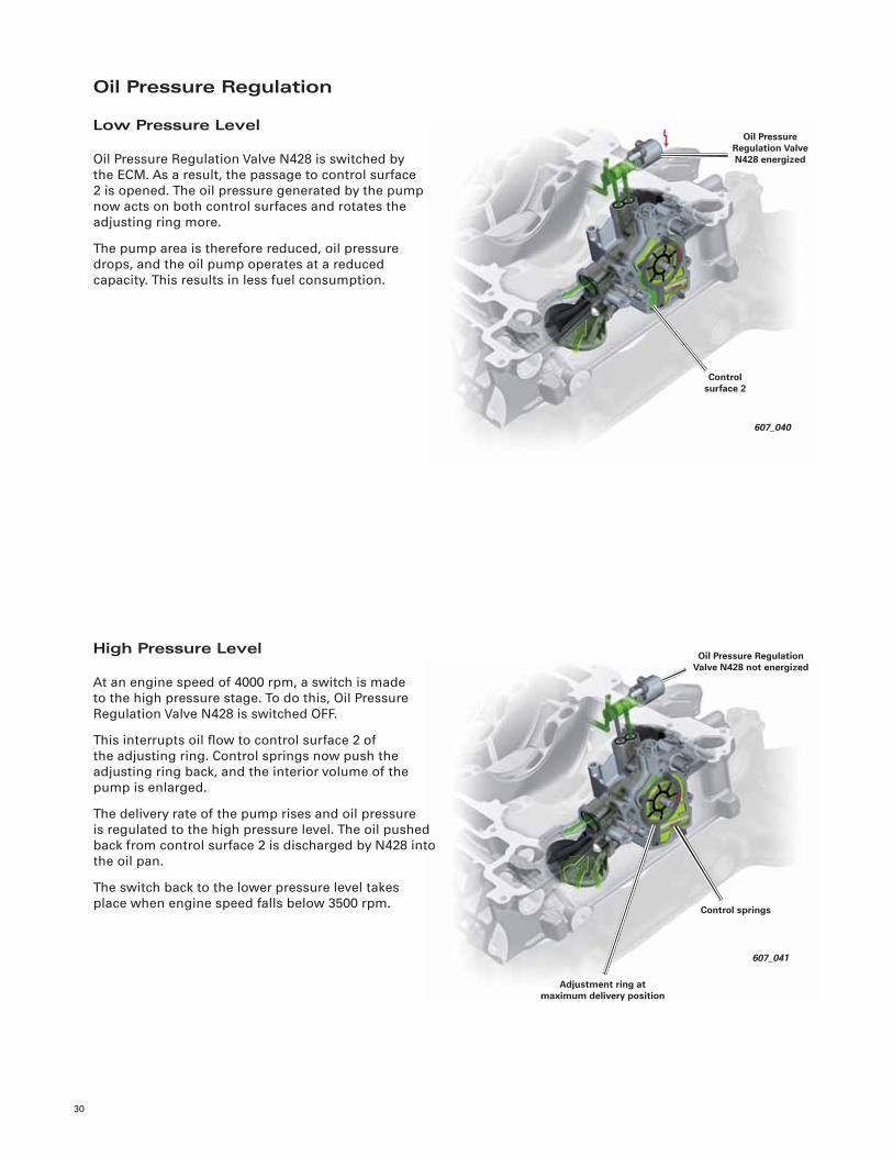
Oil Pressure Regulation
Low Pressure Level
Oil Pressure Regulation Valve N428 is switched by
the ECM. As a result, the passage to control surface
2 is opened. The oil pressure generated by the pump
now acts on both control surfaces and rotates the
adjusting ring more.
The pump area is therefore reduced, oil pressure
drops, and the oil pump operates at a reduced
capacity. This results in less fuel consumption.
607_041
Oil Pressure Regulation Valve N428 not energized
Control springs
Adjustment ring at maximum delivery position
Control surface 2
Oil Pressure Regulation Valve N428 energized
607_040
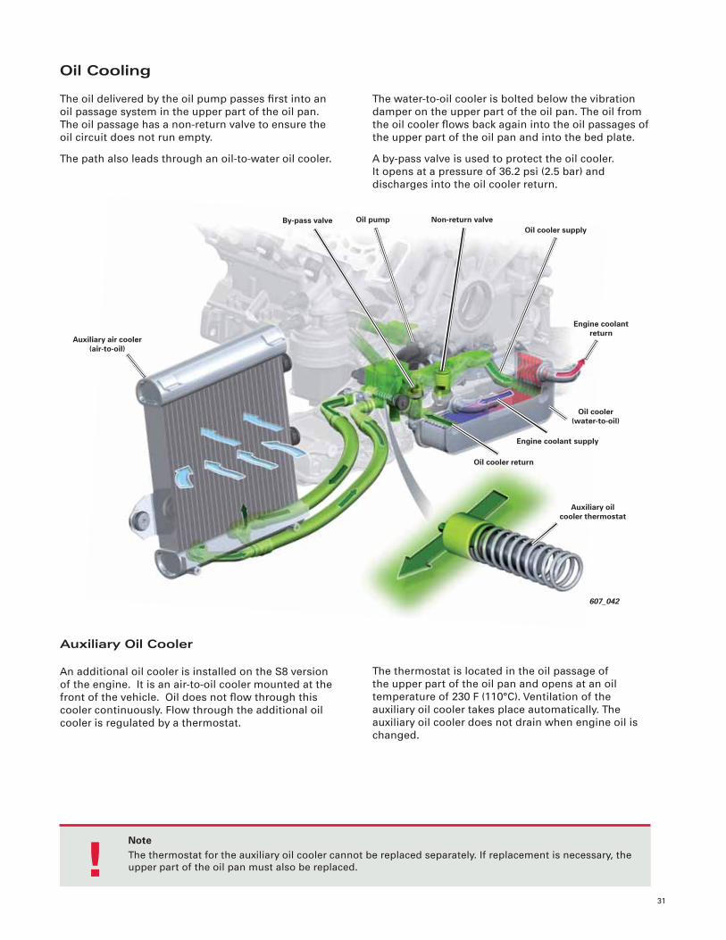
High Pressure Level
At an engine speed of 4000 rpm, a switch is made
to the high pressure stage. To do this, Oil Pressure
Regulation Valve N428 is switched OFF.
This interrupts oil fl ow to control surface 2 of
the adjusting ring. Control springs now push the
adjusting ring back, and the interior volume of the
pump is enlarged.
The delivery rate of the pump rises and oil pressure
is regulated to the high pressure level. The oil pushed
back from control surface 2 is discharged by N428 into
the oil pan.
The switch back to the lower pressure level takes
place when engine speed falls below 3500 rpm.
31
607_042
Non-return valveOil pumpBy-pass valve
Auxiliary air cooler (air-to-oil)
Engine coolant return
Oil cooler supply
Oil cooler return
Engine coolant supply
Oil cooler (water-to-oil)
Auxiliary oil cooler thermostat
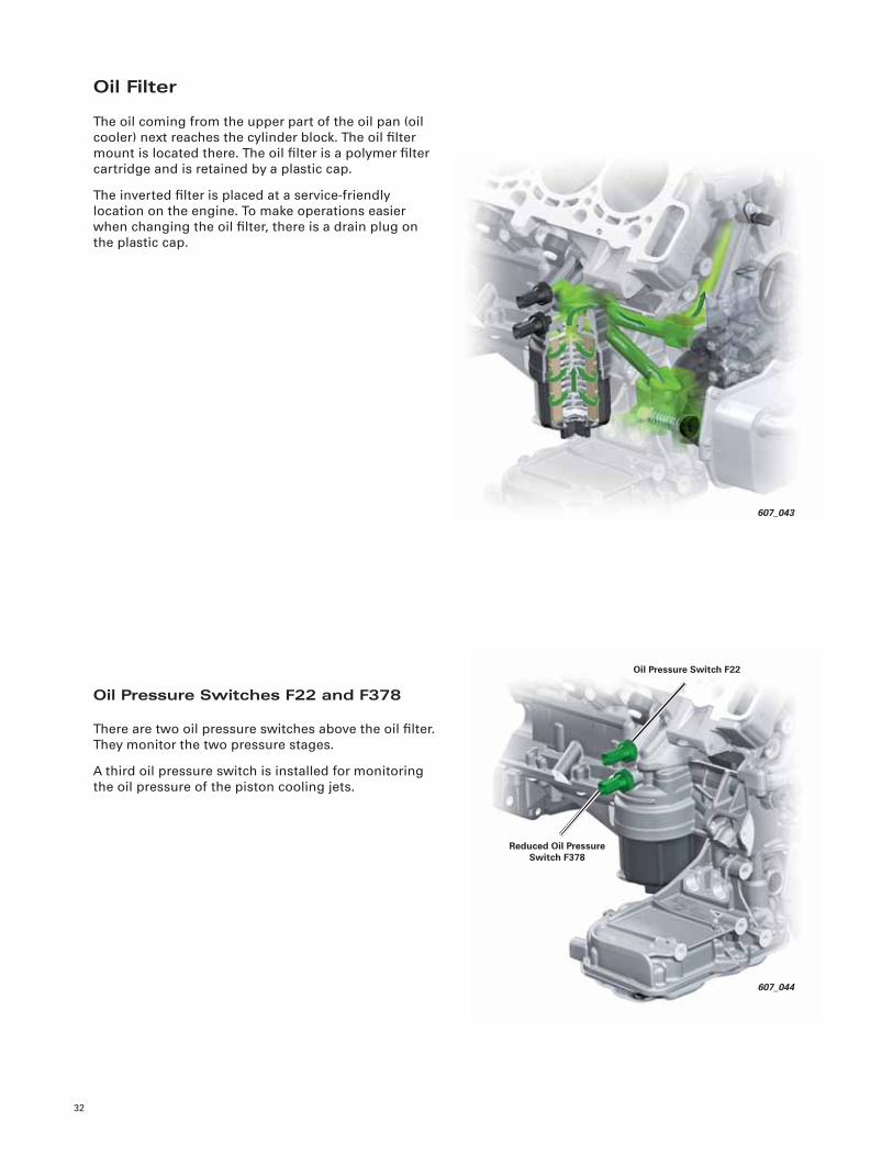
Oil Cooling
The oil delivered by the oil pump passes fi rst into an
oil passage system in the upper part of the oil pan.
The oil passage has a non-return valve to ensure the
oil circuit does not run empty.
The path also leads through an oil-to-water oil cooler.
Auxiliary Oil Cooler
An additional oil cooler is installed on the S8 version
of the engine. It is an air-to-oil cooler mounted at the
front of the vehicle. Oil does not fl ow through this
cooler continuously. Flow through the additional oil
cooler is regulated by a thermostat.
The water-to-oil cooler is bolted below the vibration
damper on the upper part of the oil pan. The oil from
the oil cooler fl ows back again into the oil passages of
the upper part of the oil pan and into the bed plate.
A by-pass valve is used to protect the oil cooler.
It opens at a pressure of 36.2 psi (2.5 bar) and
discharges into the oil cooler return.
The thermostat is located in the oil passage of
the upper part of the oil pan and opens at an oil
temperature of 230 F (110°C). Ventilation of the
auxiliary oil cooler takes place automatically. The
auxiliary oil cooler does not drain when engine oil is
changed.
NoteThe thermostat for the auxiliary oil cooler cannot be replaced separately. If replacement is necessary, the
upper part of the oil pan must also be replaced. !
32
607_043
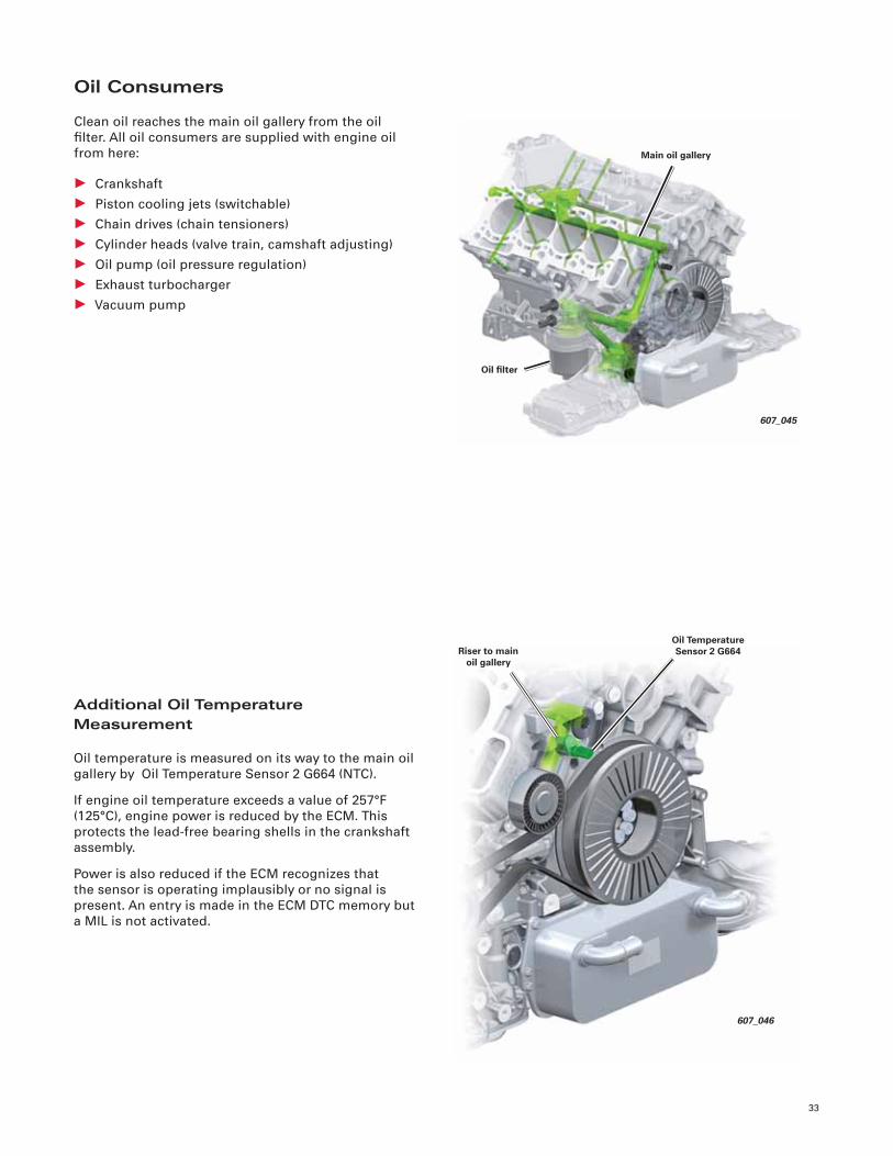
Oil Filter
The oil coming from the upper part of the oil pan (oil
cooler) next reaches the cylinder block. The oil fi lter
mount is located there. The oil fi lter is a polymer fi lter
cartridge and is retained by a plastic cap.
The inverted fi lter is placed at a service-friendly
location on the engine. To make operations easier
when changing the oil fi lter, there is a drain plug on
the plastic cap.
Oil Pressure Switches F22 and F378
There are two oil pressure switches above the oil fi lter.
They monitor the two pressure stages.
A third oil pressure switch is installed for monitoring
the oil pressure of the piston cooling jets.
607_044
Reduced Oil Pressure Switch F378
Oil Pressure Switch F22
33
Oil Consumers
Clean oil reaches the main oil gallery from the oil
fi lter. All oil consumers are supplied with engine oil
from here:
• Crankshaft
• Piston cooling jets (switchable)
• Chain drives (chain tensioners)
• Cylinder heads (valve train, camshaft adjusting)
• Oil pump (oil pressure regulation)
• Exhaust turbocharger
• Vacuum pump
Additional Oil Temperature Measurement
Oil temperature is measured on its way to the main oil
gallery by Oil Temperature Sensor 2 G664 (NTC).
If engine oil temperature exceeds a value of 257°F
(125°C), engine power is reduced by the ECM. This
protects the lead-free bearing shells in the crankshaft
assembly.
Power is also reduced if the ECM recognizes that
the sensor is operating implausibly or no signal is
present. An entry is made in the ECM DTC memory but
a MIL is not activated.
607_046
Oil Temperature Sensor 2 G664Riser to main
oil gallery
Oil fi lter
Main oil gallery
607_045
34
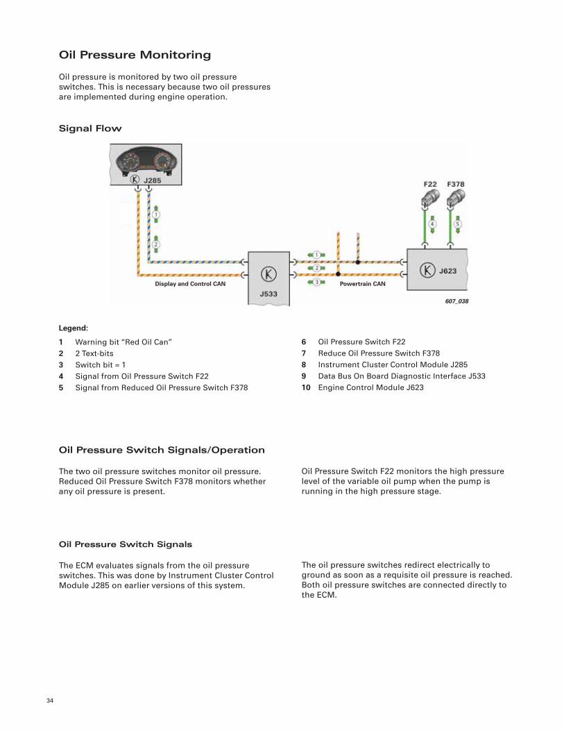
Oil Pressure Monitoring
Oil pressure is monitored by two oil pressure
switches. This is necessary because two oil pressures
are implemented during engine operation.
Signal Flow
Oil Pressure Switch Signals/Operation
The two oil pressure switches monitor oil pressure.
Reduced Oil Pressure Switch F378 monitors whether
any oil pressure is present.
Oil Pressure Switch Signals
The ECM evaluates signals from the oil pressure
switches. This was done by Instrument Cluster Control
Module J285 on earlier versions of this system.
Oil Pressure Switch F22 monitors the high pressure
level of the variable oil pump when the pump is
running in the high pressure stage.
The oil pressure switches redirect electrically to
ground as soon as a requisite oil pressure is reached.
Both oil pressure switches are connected directly to
the ECM.
Legend:
1 Warning bit “Red Oil Can”
2 2 Text-bits
3 Switch bit = 1
4 Signal from Oil Pressure Switch F22
5 Signal from Reduced Oil Pressure Switch F378
6 Oil Pressure Switch F22
7 Reduce Oil Pressure Switch F378
8 Instrument Cluster Control Module J285
9 Data Bus On Board Diagnostic Interface J533
10 Engine Control Module J623
607_038
Display and Control CAN Powertrain CAN
35
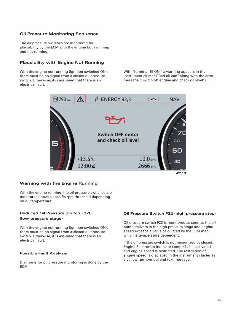
Oil Pressure Monitoring Sequence
The oil pressure switches are monitored for
plausibility by the ECM with the engine both running
and not running.
Plausibility with Engine Not Running
With the engine not running (ignition switched ON),
there must be no signal from a closed oil pressure
switch. Otherwise, it is assumed that there is an
electrical fault.
With “terminal 15 ON,” a warning appears in the
instrument cluster (“Red oil can” along with the error
message “Switch off engine and check oil level”).
Warning with the Engine Running
With the engine running, the oil pressure switches are
monitored above a specifi c rpm threshold depending
on oil temperature.
Reduced Oil Pressure Switch F378(low pressure stage)
With the engine not running (ignition switched ON),
there must be no signal from a closed oil pressure
switch. Otherwise, it is assumed that there is an
electrical fault.
Oil Pressure Switch F22 (high pressure step)
Oil pressure switch F22 is monitored as soon as the oil
pump delivers in the high pressure stage and engine
speed exceeds a value calculated by the ECM map,
which is temperature dependent.
If the oil pressure switch is not recognized as closed,
Engine Electronics Indicator Lamp K149 is activated
and engine speed is restricted. The restriction of
engine speed is displayed in the instrument cluster as
a yellow rpm symbol and text message.
Possible Fault Analysis
Diagnosis for oil pressure monitoring is done by the
ECM.
Switch OFF motorand check oil level
607_039
36
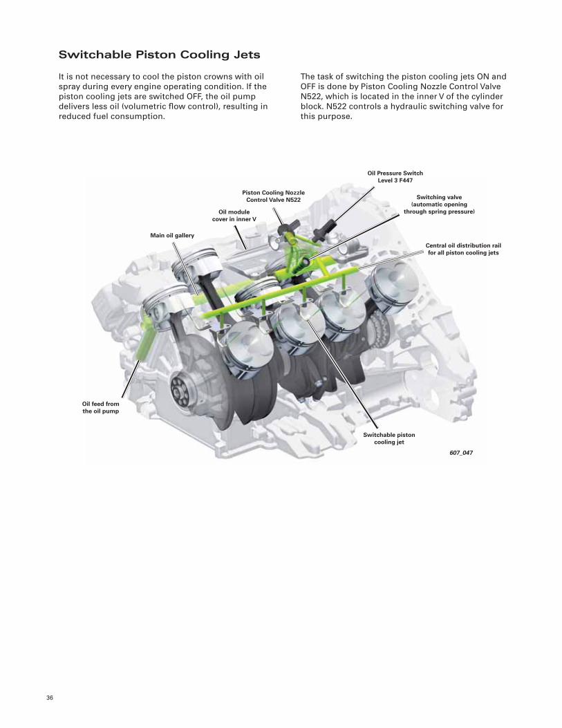
Switchable Piston Cooling Jets
It is not necessary to cool the piston crowns with oil
spray during every engine operating condition. If the
piston cooling jets are switched OFF, the oil pump
delivers less oil (volumetric fl ow control), resulting in
reduced fuel consumption.
The task of switching the piston cooling jets ON and
OFF is done by Piston Cooling Nozzle Control Valve
N522, which is located in the inner V of the cylinder
block. N522 controls a hydraulic switching valve for
this purpose.
607_047
Oil Pressure Switch Level 3 F447
Switching valve(automatic opening
through spring pressure)
Piston Cooling Nozzle Control Valve N522
Oil module cover in inner V
Main oil gallery
Switchable piston cooling jet
Central oil distribution rail for all piston cooling jets
Oil feed from the oil pump
37
Operation
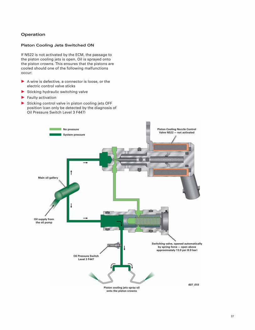
Piston Cooling Jets Switched ON
If N522 is not activated by the ECM, the passage to
the piston cooling jets is open. Oil is sprayed onto
the piston crowns. This ensures that the pistons are
cooled should one of the following malfunctions
occur:
• A wire is defective, a connector is loose, or the
electric control valve sticks
• Sticking hydraulic switching valve
• Faulty activation
• Sticking control valve in piston cooling jets OFF
position (can only be detected by the diagnosis of
Oil Pressure Switch Level 3 F447)
607_015
Oil Pressure Switch Level 3 F447
Oil supply from the oil pump
Piston cooling jets spray oil onto the piston crowns
Main oil gallery
Piston Cooling Nozzle Control Valve N522 — not activated
No pressure
System pressure
Switching valve, opened automatically by spring force — open above
approximately 13.0 psi (0.9 bar)
38
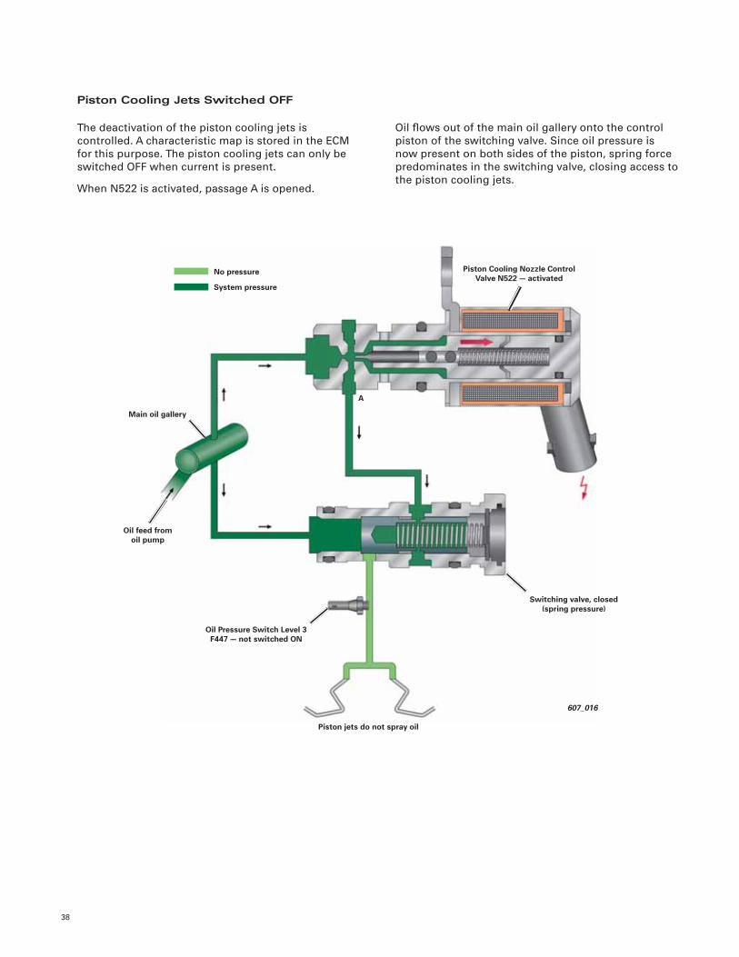
Piston Cooling Jets Switched OFF
The deactivation of the piston cooling jets is
controlled. A characteristic map is stored in the ECM
for this purpose. The piston cooling jets can only be
switched OFF when current is present.
When N522 is activated, passage A is opened.
Oil fl ows out of the main oil gallery onto the control
piston of the switching valve. Since oil pressure is
now present on both sides of the piston, spring force
predominates in the switching valve, closing access to
the piston cooling jets.
607_016
Oil Pressure Switch Level 3 F447 — not switched ON
Switching valve, closed (spring pressure)
Piston jets do not spray oil
Piston Cooling Nozzle Control Valve N522 — activated
A
No pressure
System pressure
Oil feed from oil pump
Main oil gallery
39
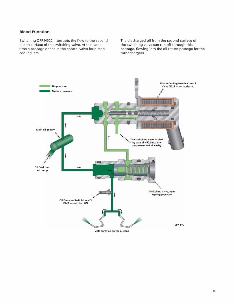
Bleed Function
Switching OFF N522 interrupts the fl ow to the second
piston surface of the switching valve. At the same
time a passage opens in the control valve for piston
cooling jets.
The discharged oil from the second surface of
the switching valve can run off through this
passage, fl owing into the oil return passage for the
turbochargers.
607_017
Oil Pressure Switch Level 3 F447 — switched ON
The switching valve is bled by way of N522 into theun-pressurized oil cavity
Piston Cooling Nozzle Control Valve N522 — not activated No pressure
System pressure
Main oil gallery
Oil feed from oil pump
Jets spray oil on the pistons
Switching valve, open (spring pressure)
40
607_049
Oil fl ow from energized control valve to the switching valve,
piston cooling jets OFF
Cover in inner V
Oil pressure from the main oil gallery
Oil Pressure Switch Level 3 F447
Oil fl ow from the switching valve by way of the de-energized control valve into the turbocharger oil return cavity (bleeding of
switching valve) piston cooling jets ON
Oil Pressure Switch Level 3 F447
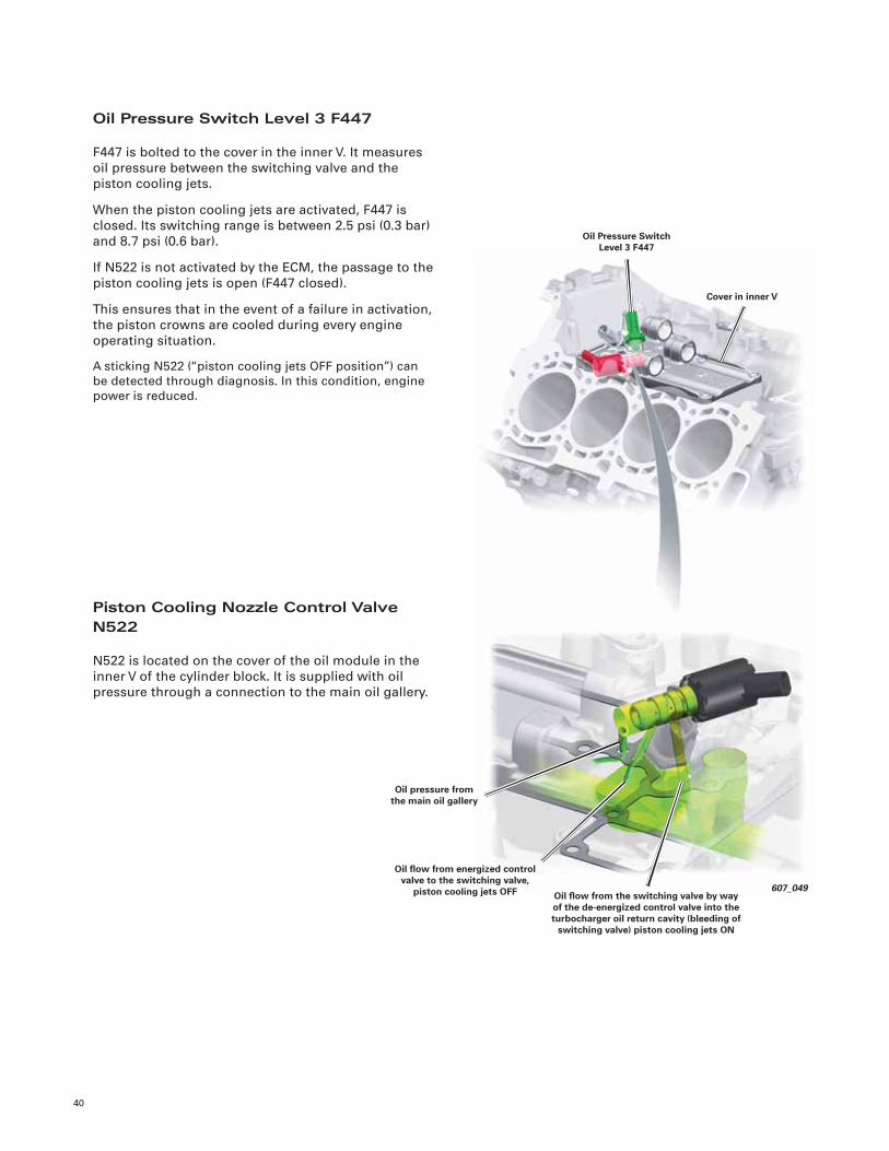
F447 is bolted to the cover in the inner V. It measures
oil pressure between the switching valve and the
piston cooling jets.
When the piston cooling jets are activated, F447 is
closed. Its switching range is between 2.5 psi (0.3 bar)
and 8.7 psi (0.6 bar).
If N522 is not activated by the ECM, the passage to the
piston cooling jets is open (F447 closed).
This ensures that in the event of a failure in activation,
the piston crowns are cooled during every engine
operating situation.
A sticking N522 (“piston cooling jets OFF position”) can
be detected through diagnosis. In this condition, engine
power is reduced.
Piston Cooling Nozzle Control Valve N522
N522 is located on the cover of the oil module in the
inner V of the cylinder block. It is supplied with oil
pressure through a connection to the main oil gallery.
41
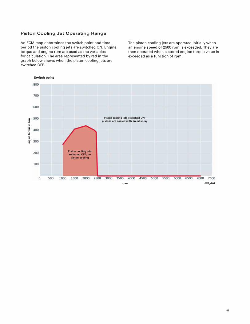
Piston Cooling Jet Operating Range
An ECM map determines the switch point and time
period the piston cooling jets are switched ON. Engine
torque and engine rpm are used as the variables
for calculation. The area represented by red in the
graph below shows when the piston cooling jets are
switched OFF.
The piston cooling jets are operated initially when
an engine speed of 2500 rpm is exceeded. They are
then operated when a stored engine torque value is
exceeded as a function of rpm.
607_048rpm
Piston cooling jets switched OFF; no
piston cooling
Eng
ine
torq
ue
in N
m
Piston cooling jets switched ON; pistons are cooled with an oil spray
Switch point
Cooling System
42
439_017
Engine coolant pump (mechanical)
Engine CoolantCirculation Pump 2 V178
(delayed shut-off for turbocharger cooling)
Switching valve for standing coolant (ITM)
Water cooled turbochargers
Water cooled generator
Map Controlled Engine Cooling Thermostat F265
Overview
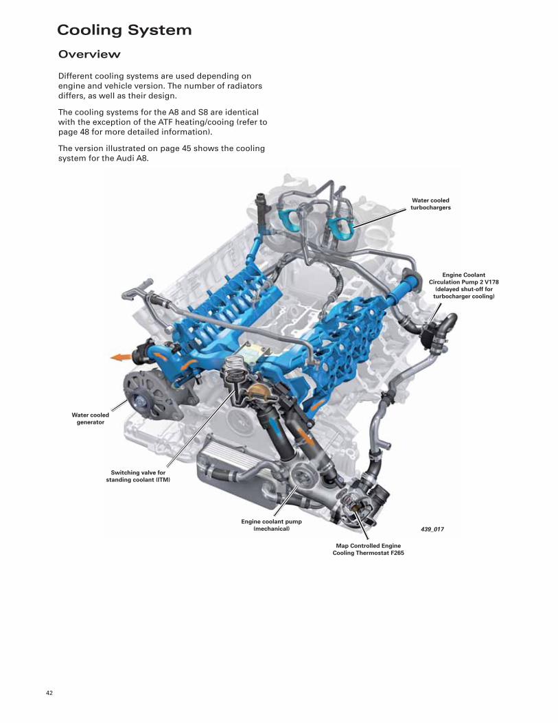
Different cooling systems are used depending on
engine and vehicle version. The number of radiators
differs, as well as their design.
The cooling systems for the A8 and S8 are identical
with the exception of the ATF heating/cooing (refer to
page 48 for more detailed information).
The version illustrated on page 45 shows the cooling
system for the Audi A8.
43
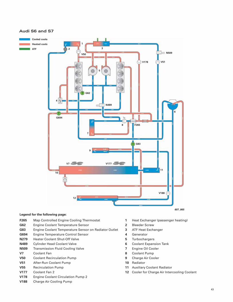
Legend for the following page:
F265 Map Controlled Engine Cooling Thermostat
G62 Engine Coolant Temperature Sensor
G83 Engine Coolant Temperature Sensor on Radiator Outlet
G694 Engine Temperature Control Sensor
N279 Heater Coolant Shut-Off Valve
N489 Cylinder Head Coolant Valve
N509 Transmission Fluid Cooling Valve
V7 Coolant Fan
V50 Coolant Recirculation Pump
V51 After-Run Coolant Pump
V55 Recirculation Pump
V177 Coolant Fan 2
V178 Engine Coolant Circulation Pump 2
V188 Charge Air Cooling Pump
1 Heat Exchanger (passenger heating)
2 Bleeder Screw
3 ATF Heat Exchanger
4 Generator
5 Turbochargers
6 Coolant Expansion Tank
7 Engine Oil Cooler
8 Coolant Pump
9 Charge Air Cooler
10 Radiator
11 Auxiliary Coolant Radiator
12 Cooler for Charge Air Intercooling Coolant
Audi S6 and S7
Cooled coolant
Heated coolant
ATF
607_065
V188
6
12
11
V177V7
9
G83
7
8
G694
F265
N489
G62
4
5
V178 V51
N509V50
3
1
2
10

Notes
44
45
607_066
V188
8
14
13
V177V7
10
G837
9
G694
F265
N489
G62
6
5
V178 V51
V50
3
1 2
1112
N509 N488
4
Legend:
F265 Map Controlled Engine Cooling Thermostat
G62 Engine Coolant Temperature Sensor
G83 Engine Coolant Temperature Sensor on Radiator Outlet
G694 Engine Temperature Control Sensor
N279 Heater Coolant Shut-Off Valve
N488 Transmission Coolant Valve
N489 Cylinder Head Coolant Valve
N509 Transmission Fluid Cooling Valve
V7 Coolant Fan
V50 Coolant Recirculation Pump
V51 After-Run Coolant Pump
V55 Recirculation Pump
V177 Coolant Fan 2
V178 Engine Coolant Circulation Pump 2
V188 Charge Air Cooling Pump
1 Heat Exchanger (front passenger compartment)
2 Heat Exchanger (rear passenger compartment)
3 Bleeder Screw
4 ATF Heat Exchanger
5 Turbochargers
6 Generator
7 Engine Oil Cooler
8 Coolant Expansion Tank
9 Coolant Pump
10 Charge Air Cooler
11 Auxiliary Radiator (A8 ‘12 only)
12 Radiator
13 Auxiliary Radiator 2
14 Radiator for Charge Air Cooling
Audi A8 and S8
Cooled coolant
Heated coolant
ATF
46
Engine Cooling Circuitand Cooling Module
Engine Coolant Pump (mechanical)
Engine coolant circulation is driven by the primary
coolant pump, which provides necessary volumetric
fl ow for:
• Cooling the engine and the turbochargers
• Flow through the engine oil cooler
The design is based on the coolant pump of the
normally aspirated 4.2L V8 FSI engine.
The pump is driven by a shaft connected by a rigid
reduction gear in the oil pump to the crankshaft. The
thermostat is fl anged to the coolant pump on the
suction side.
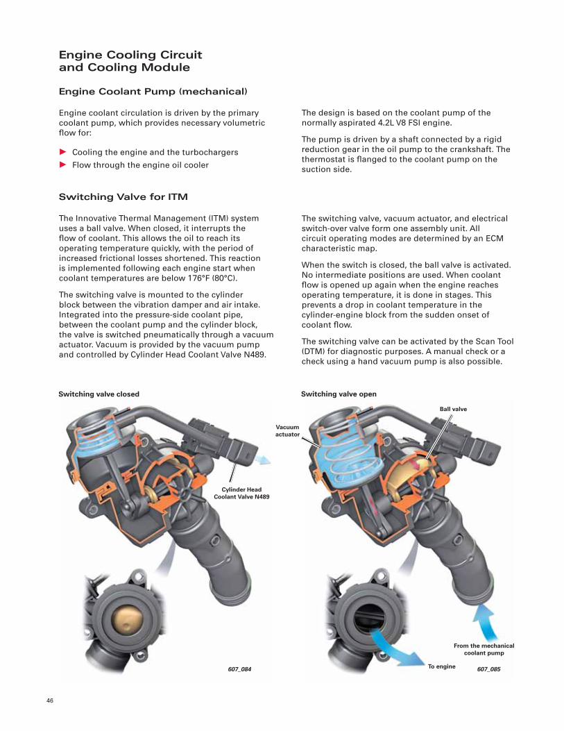
Switching Valve for ITM
The Innovative Thermal Management (ITM) system
uses a ball valve. When closed, it interrupts the
fl ow of coolant. This allows the oil to reach its
operating temperature quickly, with the period of
increased frictional losses shortened. This reaction
is implemented following each engine start when
coolant temperatures are below 176°F (80°C).
The switching valve is mounted to the cylinder
block between the vibration damper and air intake.
Integrated into the pressure-side coolant pipe,
between the coolant pump and the cylinder block,
the valve is switched pneumatically through a vacuum
actuator. Vacuum is provided by the vacuum pump
and controlled by Cylinder Head Coolant Valve N489.
The switching valve, vacuum actuator, and electrical
switch-over valve form one assembly unit. All
circuit operating modes are determined by an ECM
characteristic map.
When the switch is closed, the ball valve is activated.
No intermediate positions are used. When coolant
fl ow is opened up again when the engine reaches
operating temperature, it is done in stages. This
prevents a drop in coolant temperature in the
cylinder-engine block from the sudden onset of
coolant fl ow.
The switching valve can be activated by the Scan Tool
(DTM) for diagnostic purposes. A manual check or a
check using a hand vacuum pump is also possible.
Cylinder Head Coolant Valve N489
607_084
Switching valve closed
607_085
From the mechanical coolant pump
Vacuum actuator
To engine
Ball valve
Switching valve open
47
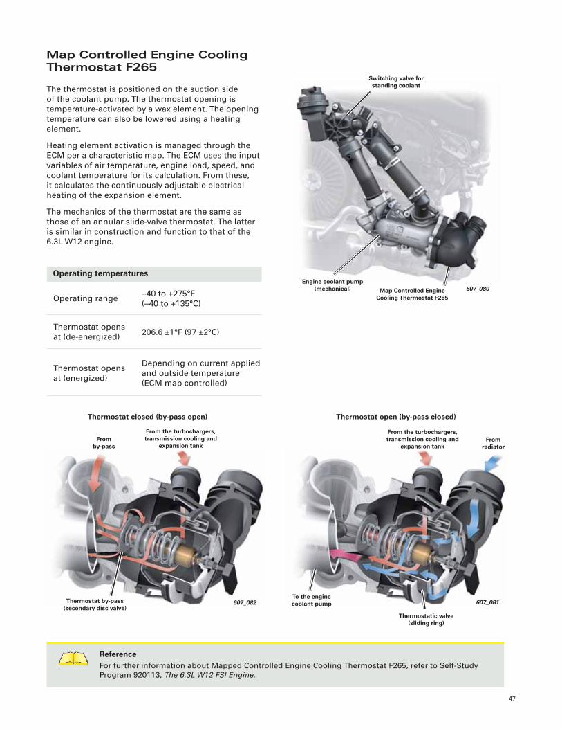
Map Controlled Engine Cooling Thermostat F265
The thermostat is positioned on the suction side
of the coolant pump. The thermostat opening is
temperature-activated by a wax element. The opening
temperature can also be lowered using a heating
element.
Heating element activation is managed through the
ECM per a characteristic map. The ECM uses the input
variables of air temperature, engine load, speed, and
coolant temperature for its calculation. From these,
it calculates the continuously adjustable electrical
heating of the expansion element.
The mechanics of the thermostat are the same as
those of an annular slide-valve thermostat. The latter
is similar in construction and function to that of the
6.3L W12 engine.
Operating temperatures
Operating range
Thermostat opens
at (de-energized)
Thermostat opens
at (energized)
–40 to +275°F
(–40 to +135°C)
206.6 ±1°F (97 ±2°C)
Depending on current applied
and outside temperature
(ECM map controlled)
ReferenceFor further information about Mapped Controlled Engine Cooling Thermostat F265, refer to Self-Study
Program 920113, The 6.3L W12 FSI Engine.
607_080
Switching valve for standing coolant
Map Controlled Engine Cooling Thermostat F265
Engine coolant pump(mechanical)
Thermostat by-pass (secondary disc valve)
From by-pass
From the turbochargers, transmission cooling and
expansion tank
607_082
Thermostat closed (by-pass open)
607_081To the engine coolant pump
From the turbochargers, transmission cooling and
expansion tankFrom
radiator
Thermostatic valve (sliding ring)
Thermostat open (by-pass closed)
48
607_068
V51
1
V178
N509
Cooled coolant
Heated coolant
ATF
Transmission FluidHeating/Cooling
An additional function of ITM is the cooling and
heating of the transmission fl uid (ATF). There are
differences in the system, depending on the engine
variant.
The two versions are:
• System 1: Audi S6, S7, and S8
• System 2: Audi A8 with 420 hp (309 kW) engine
System 1 in Audi S6, S7, and S8
Only the transmission cooling system is used.
Transmission Fluid Cooling Valve N509 and After-Run
Coolant Pump V51 are installed in the ATF cooling
circuit. N509 and V51 are activated by the ECM.
V51 is switched on by the ECM when the ATF
temperature is above 204.8°F (96°C). N509 is opened
at temperatures greater than 197.6°F (92°C) and closed
again at temperatures less than 176°F (80°C).
Legend:
1 ATF Heat Exchanger
N488 Transmission Coolant Valve
N509 Transmission Fluid Cooling Valve
V51 After-Run Coolant Pump
V178 Engine Coolant Circulation Pump 2
[Illustration shows Audi S8]
607_071
49
607_067
V51
1
V178
N488
Cooled coolant
Heated coolant
ATF
N509
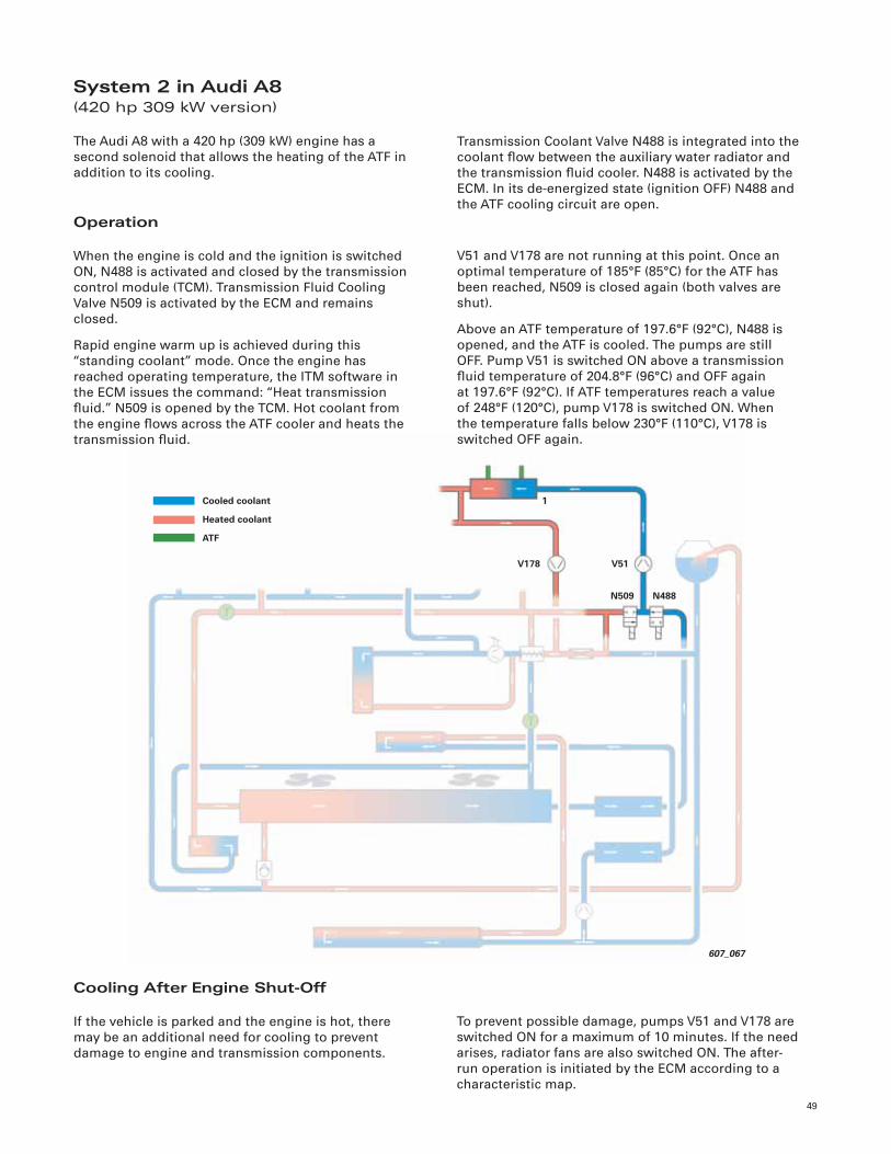
System 2 in Audi A8(420 hp 309 kW version)
The Audi A8 with a 420 hp (309 kW) engine has a
second solenoid that allows the heating of the ATF in
addition to its cooling.
Operation
When the engine is cold and the ignition is switched
ON, N488 is activated and closed by the transmission
control module (TCM). Transmission Fluid Cooling
Valve N509 is activated by the ECM and remains
closed.
Rapid engine warm up is achieved during this
“standing coolant” mode. Once the engine has
reached operating temperature, the ITM software in
the ECM issues the command: “Heat transmission
fl uid.” N509 is opened by the TCM. Hot coolant from
the engine fl ows across the ATF cooler and heats the
transmission fl uid.
Transmission Coolant Valve N488 is integrated into the
coolant fl ow between the auxiliary water radiator and
the transmission fl uid cooler. N488 is activated by the
ECM. In its de-energized state (ignition OFF) N488 and
the ATF cooling circuit are open.
V51 and V178 are not running at this point. Once an
optimal temperature of 185°F (85°C) for the ATF has
been reached, N509 is closed again (both valves are
shut).
Above an ATF temperature of 197.6°F (92°C), N488 is
opened, and the ATF is cooled. The pumps are still
OFF. Pump V51 is switched ON above a transmission
fl uid temperature of 204.8°F (96°C) and OFF again
at 197.6°F (92°C). If ATF temperatures reach a value
of 248°F (120°C), pump V178 is switched ON. When
the temperature falls below 230°F (110°C), V178 is
switched OFF again.
Cooling After Engine Shut-Off
If the vehicle is parked and the engine is hot, there
may be an additional need for cooling to prevent
damage to engine and transmission components.
To prevent possible damage, pumps V51 and V178 are
switched ON for a maximum of 10 minutes. If the need
arises, radiator fans are also switched ON. The after-
run operation is initiated by the ECM according to a
characteristic map.
50
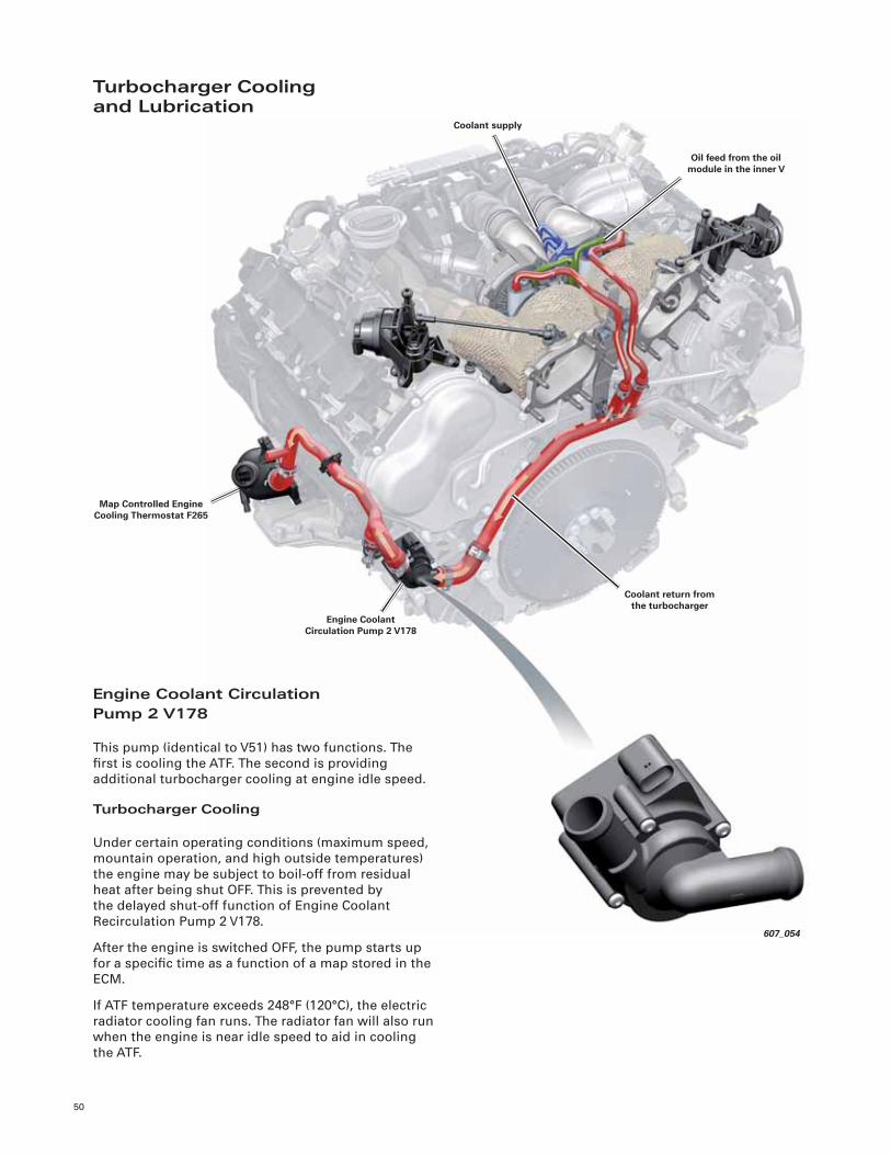
607_054
Engine Coolant Circulation Pump 2 V178
Oil feed from the oil module in the inner V
Map Controlled Engine Cooling Thermostat F265
Coolant supply
Coolant return from the turbocharger
Turbocharger Coolingand Lubrication
Engine Coolant CirculationPump 2 V178
This pump (identical to V51) has two functions. The
fi rst is cooling the ATF. The second is providing
additional turbocharger cooling at engine idle speed.
Turbocharger Cooling
Under certain operating conditions (maximum speed,
mountain operation, and high outside temperatures)
the engine may be subject to boil-off from residual
heat after being shut OFF. This is prevented by
the delayed shut-off function of Engine Coolant
Recirculation Pump 2 V178.
After the engine is switched OFF, the pump starts up
for a specifi c time as a function of a map stored in the
ECM.
If ATF temperature exceeds 248°F (120°C), the electric
radiator cooling fan runs. The radiator fan will also run
when the engine is near idle speed to aid in cooling
the ATF.
51
607_055
Charge Air Cooling Pump V188
Charge air cooler(S7 version)
Charge air cooler in inner V(air-to-water)
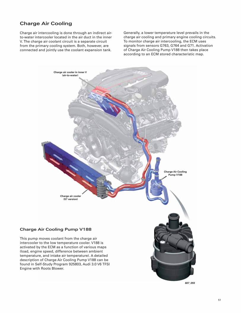
Charge Air Cooling
Charge air intercooling is done through an indirect air-
to-water intercooler located in the air duct in the inner
V. The charge air coolant circuit is a separate circuit
from the primary cooling system. Both, however, are
connected and jointly use the coolant expansion tank.
Generally, a lower temperature level prevails in the
charge air cooling and primary engine cooling circuits.
To monitor charge air intercooling, the ECM uses
signals from sensors G763, G764 and G71. Activation
of Charge Air Cooling Pump V188 then takes place
according to an ECM stored characteristic map.
Charge Air Cooling Pump V188
This pump moves coolant from the charge air
intercooler to the low temperature cooler. V188 is
activated by the ECM as a function of various maps
(load, engine speed, difference between ambient
temperature, and intake air temperature). A detailed
description of Charge Air Cooling Pump V188 can be
found in Self-Study Program 925803, Audi 3.0 V6 TFSI
Engine with Roots Blower.
52
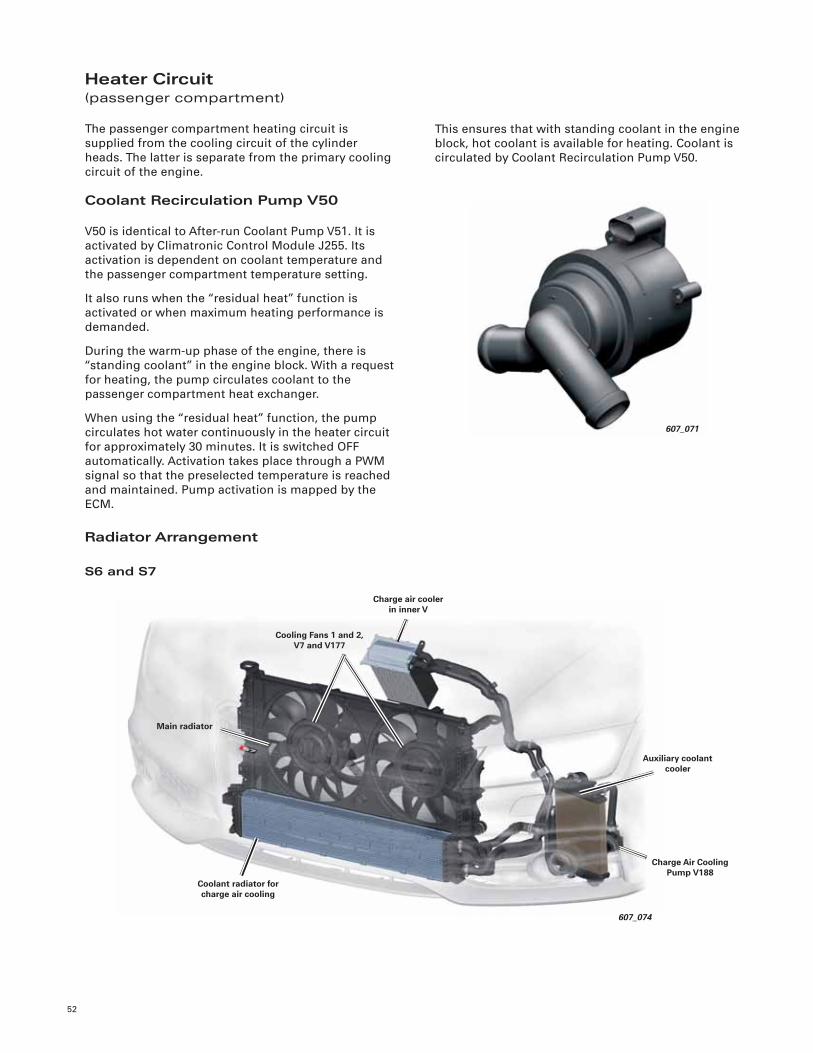
Heater Circuit(passenger compartment)
The passenger compartment heating circuit is
supplied from the cooling circuit of the cylinder
heads. The latter is separate from the primary cooling
circuit of the engine.
This ensures that with standing coolant in the engine
block, hot coolant is available for heating. Coolant is
circulated by Coolant Recirculation Pump V50.
Coolant Recirculation Pump V50
V50 is identical to After-run Coolant Pump V51. It is
activated by Climatronic Control Module J255. Its
activation is dependent on coolant temperature and
the passenger compartment temperature setting.
It also runs when the “residual heat” function is
activated or when maximum heating performance is
demanded.
During the warm-up phase of the engine, there is
“standing coolant” in the engine block. With a request
for heating, the pump circulates coolant to the
passenger compartment heat exchanger.
When using the “residual heat” function, the pump
circulates hot water continuously in the heater circuit
for approximately 30 minutes. It is switched OFF
automatically. Activation takes place through a PWM
signal so that the preselected temperature is reached
and maintained. Pump activation is mapped by the
ECM.
Radiator Arrangement
S6 and S7
607_071
607_074
Charge air cooler in inner V
Main radiator
Coolant radiator for charge air cooling
Auxiliary coolant cooler
Cooling Fans 1 and 2,V7 and V177
Charge Air Cooling Pump V188
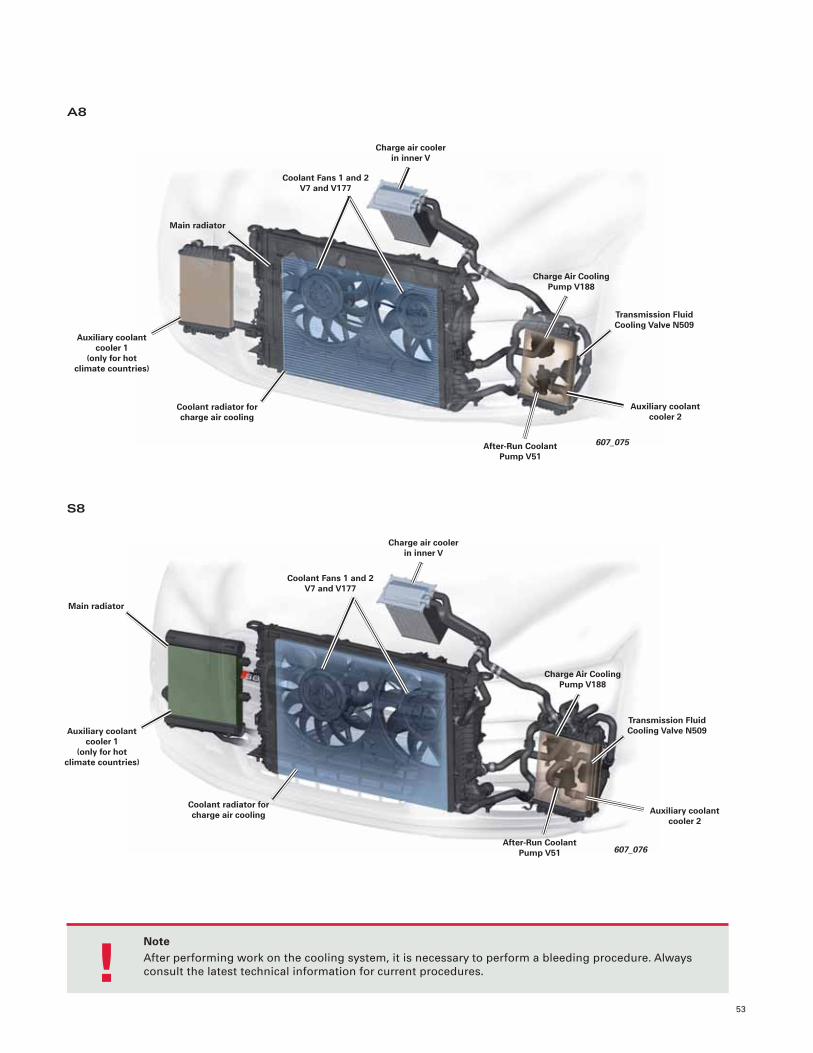
53
A8
S8
NoteAfter performing work on the cooling system, it is necessary to perform a bleeding procedure. Always
consult the latest technical information for current procedures. !
Auxiliary coolant cooler 1
(only for hot climate countries)
Coolant Fans 1 and 2 V7 and V177
Main radiator
Charge air cooler in inner V
607_075
Charge Air Cooling Pump V188
Transmission Fluid Cooling Valve N509
After-Run Coolant Pump V51
Coolant radiator for charge air cooling
Auxiliary coolant cooler 2
607_076
Auxiliary coolant cooler 1
(only for hot climate countries)
Coolant Fans 1 and 2 V7 and V177
Main radiator
Charge air cooler in inner V
Charge Air Cooling Pump V188
Transmission Fluid Cooling Valve N509
After-Run Coolant Pump V51
Coolant radiator for charge air cooling Auxiliary coolant
cooler 2
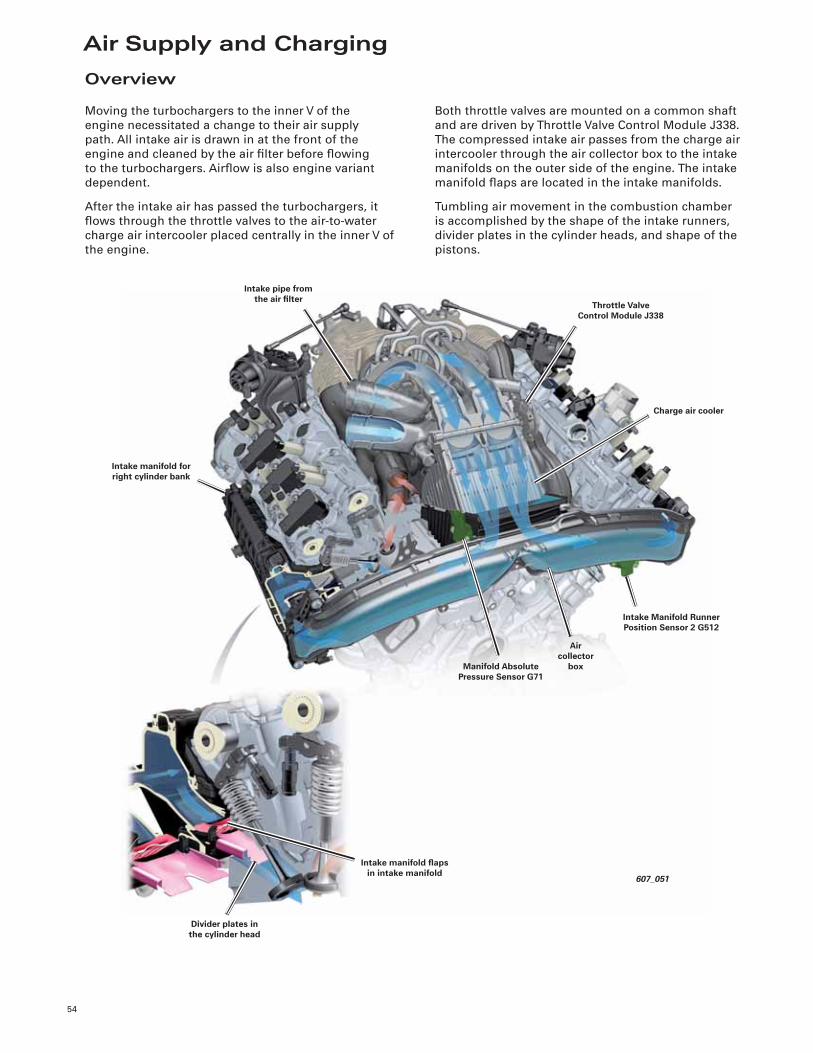
Air Supply and Charging
54
Overview
Moving the turbochargers to the inner V of the
engine necessitated a change to their air supply
path. All intake air is drawn in at the front of the
engine and cleaned by the air fi lter before fl owing
to the turbochargers. Airfl ow is also engine variant
dependent.
After the intake air has passed the turbochargers, it
fl ows through the throttle valves to the air-to-water
charge air intercooler placed centrally in the inner V of
the engine.
Both throttle valves are mounted on a common shaft
and are driven by Throttle Valve Control Module J338.
The compressed intake air passes from the charge air
intercooler through the air collector box to the intake
manifolds on the outer side of the engine. The intake
manifold fl aps are located in the intake manifolds.
Tumbling air movement in the combustion chamber
is accomplished by the shape of the intake runners,
divider plates in the cylinder heads, and shape of the
pistons.
607_051
Intake manifold fl aps in intake manifold
Air collector
box
Divider plates in the cylinder head
Intake Manifold Runner Position Sensor 2 G512
Manifold Absolute Pressure Sensor G71
Charge air cooler
Throttle Valve Control Module J338
Intake pipe from the air fi lter
Intake manifold for right cylinder bank
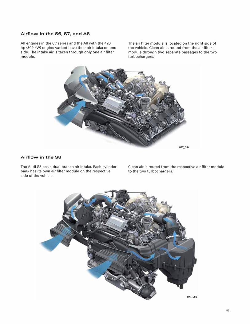
55
Airfl ow in the S6, S7, and A8
All engines in the C7 series and the A8 with the 420
hp (309 kW) engine variant have their air intake on one
side. The intake air is taken through only one air fi lter
module.
The air fi lter module is located on the right side of
the vehicle. Clean air is routed from the air fi lter
module through two separate passages to the two
turbochargers.
Airfl ow in the S8
The Audi S8 has a dual-branch air intake. Each cylinder
bank has its own air fi lter module on the respective
side of the vehicle.
Clean air is routed from the respective air fi lter module
to the two turbochargers.
607_052
607_094
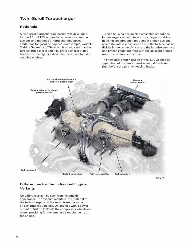
56
Twin-Scroll Turbocharger
Rationale
A twin-scroll turbocharging design was developed
for the 4.0L V8 TFSI engine because more common
designs and methods of turbocharging posed
limitations for gasoline engines. For example, Variable
Turbine Geometry (VTG), which is already standard in
turbocharged diesel engines, proved unacceptable
because of the higher exhaust temperatures found in
gasoline engines.
Turbine housing design also presented limitations.
In passenger cars with twin turbochargers, turbine
housings are predominantly single-branch designs,
where the intake cross-section into the turbine has no
divider in the center. As a result, the impulse energy of
one branch could interfere with the adjacent branch
over this common entry area.
The new dual branch design of the 4.0L V8 enabled
separation of the two exhaust manifold tracts until
right before the turbine housing intake.
Differences for the Individual Engine Variants
No differences can be seen from its outside
appearance. The exhaust manifold, the material of
the turbocharger, and the turbine are the same on
all performance versions. On engines with a power
output of 520 hp (382 kW) the compressor wheels are
larger, providing for the greater air requirements of
the engine.
607_012
Turbocharger 1
Dual branch exhaust fl ow until just before turbocharger
Coolant connections
Vacuum actuator for charge pressure control
Charge air cooler in inner V
Twin wastegate fl ap
Turbocharger 2
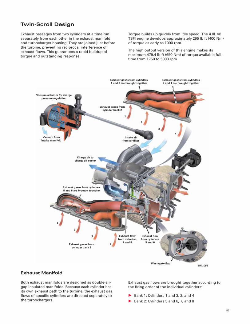
57
Twin-Scroll Design
Exhaust passages from two cylinders at a time run
separately from each other in the exhaust manifold
and turbocharger housing. They are joined just before
the turbine, preventing reciprocal interference of
exhaust fl ows. This guarantees a rapid buildup of
torque and outstanding response.
Torque builds up quickly from idle speed. The 4.0L V8
TSFI engine develops approximately 295 lb ft (400 Nm)
of torque as early as 1000 rpm.
The high output version of this engine makes its
maximum 479.4 lb ft (650 Nm) of torque available full-
time from 1750 to 5000 rpm.
Exhaust Manifold
Both exhaust manifolds are designed as double-air-
gap insulated manifolds. Because each cylinder has
its own exhaust path to the turbine, the exhaust gas
fl ows of specifi c cylinders are directed separately to
the turbochargers.
Exhaust gas fl ows are brought together according to
the fi ring order of the individual cylinders:
• Bank 1: Cylinders 1 and 3, 2, and 4
• Bank 2: Cylinders 5 and 6, 7, and 8
607_053
Exhaust gases from cylinders 2 and 4 are brought together
Exhaust gases from cylinder bank 2
Exhaust gases from cylinder bank 2
Exhaust gases from cylinders 1 and 3 are brought together
1
2
3
4
Vacuum actuator for charge pressure regulation
Vacuum from intake manifold
Intake air from air fi lter
Exhaust gases from cylinders 5 and 6 are brought together
Charge air to charge air cooler
5
6
7
8
Wastegate fl ap
Exhaust fl ow from cylinders
7 and 8
Exhaust fl ow from cylinders
5 and 6
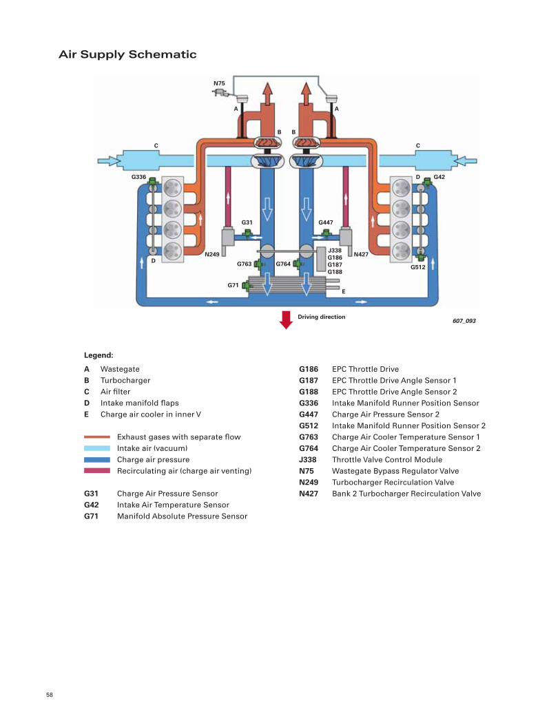
58
Air Supply Schematic
G186 EPC Throttle Drive
G187 EPC Throttle Drive Angle Sensor 1
G188 EPC Throttle Drive Angle Sensor 2
G336 Intake Manifold Runner Position Sensor
G447 Charge Air Pressure Sensor 2
G512 Intake Manifold Runner Position Sensor 2
G763 Charge Air Cooler Temperature Sensor 1
G764 Charge Air Cooler Temperature Sensor 2
J338 Throttle Valve Control Module
N75 Wastegate Bypass Regulator Valve
N249 Turbocharger Recirculation Valve
N427 Bank 2 Turbocharger Recirculation Valve
Legend:
A Wastegate
B Turbocharger
C Air fi lter
D Intake manifold fl aps
E Charge air cooler in inner V
Exhaust gases with separate fl ow
Intake air (vacuum)
Charge air pressure
Recirculating air (charge air venting)
G31 Charge Air Pressure Sensor
G42 Intake Air Temperature Sensor
G71 Manifold Absolute Pressure Sensor
607_093Driving direction
J338G186G187G188
G764
N75
N427
E
G763
G71
N249D
D
B B
C C
G512
G31 G447
G336 G42
AA
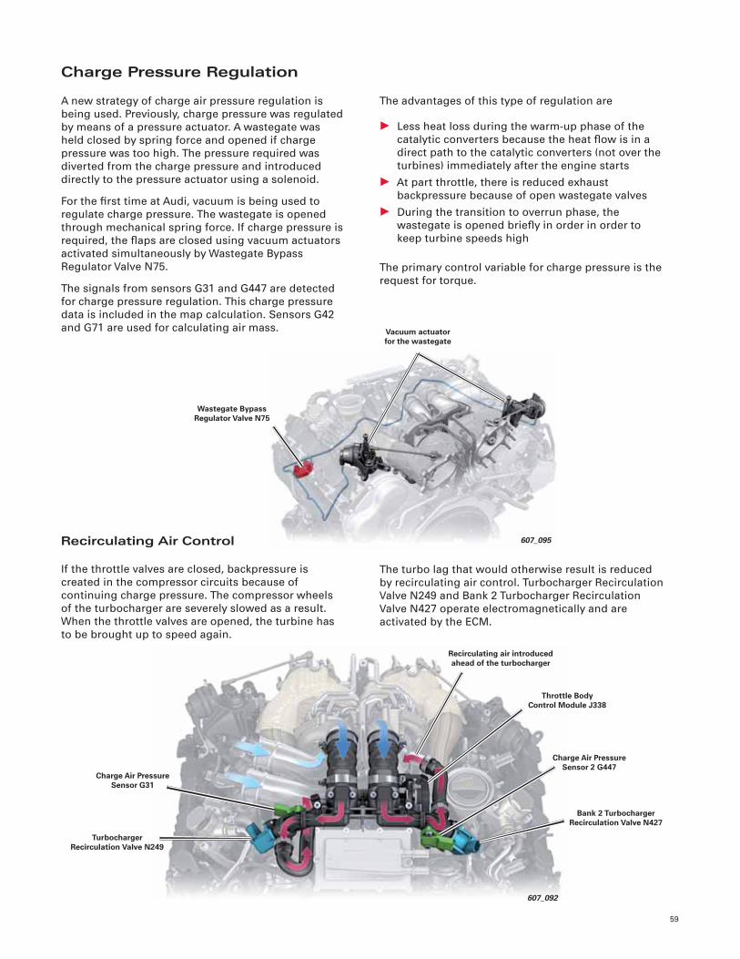
59
Vacuum actuator for the wastegate
Wastegate Bypass Regulator Valve N75
607_095
Charge Pressure Regulation
A new strategy of charge air pressure regulation is
being used. Previously, charge pressure was regulated
by means of a pressure actuator. A wastegate was
held closed by spring force and opened if charge
pressure was too high. The pressure required was
diverted from the charge pressure and introduced
directly to the pressure actuator using a solenoid.
For the fi rst time at Audi, vacuum is being used to
regulate charge pressure. The wastegate is opened
through mechanical spring force. If charge pressure is
required, the fl aps are closed using vacuum actuators
activated simultaneously by Wastegate Bypass
Regulator Valve N75.
The signals from sensors G31 and G447 are detected
for charge pressure regulation. This charge pressure
data is included in the map calculation. Sensors G42
and G71 are used for calculating air mass.
The advantages of this type of regulation are
• Less heat loss during the warm-up phase of the
catalytic converters because the heat fl ow is in a
direct path to the catalytic converters (not over the
turbines) immediately after the engine starts
• At part throttle, there is reduced exhaust
backpressure because of open wastegate valves
• During the transition to overrun phase, the
wastegate is opened briefl y in order in order to
keep turbine speeds high
The primary control variable for charge pressure is the
request for torque.
Recirculating Air Control
If the throttle valves are closed, backpressure is
created in the compressor circuits because of
continuing charge pressure. The compressor wheels
of the turbocharger are severely slowed as a result.
When the throttle valves are opened, the turbine has
to be brought up to speed again.
The turbo lag that would otherwise result is reduced
by recirculating air control. Turbocharger Recirculation
Valve N249 and Bank 2 Turbocharger Recirculation
Valve N427 operate electromagnetically and are
activated by the ECM.
607_092
Charge Air Pressure Sensor G31
Recirculating air introduced ahead of the turbocharger
Throttle Body Control Module J338
Turbocharger Recirculation Valve N249
Charge Air Pressure Sensor 2 G447
Bank 2 Turbocharger Recirculation Valve N427
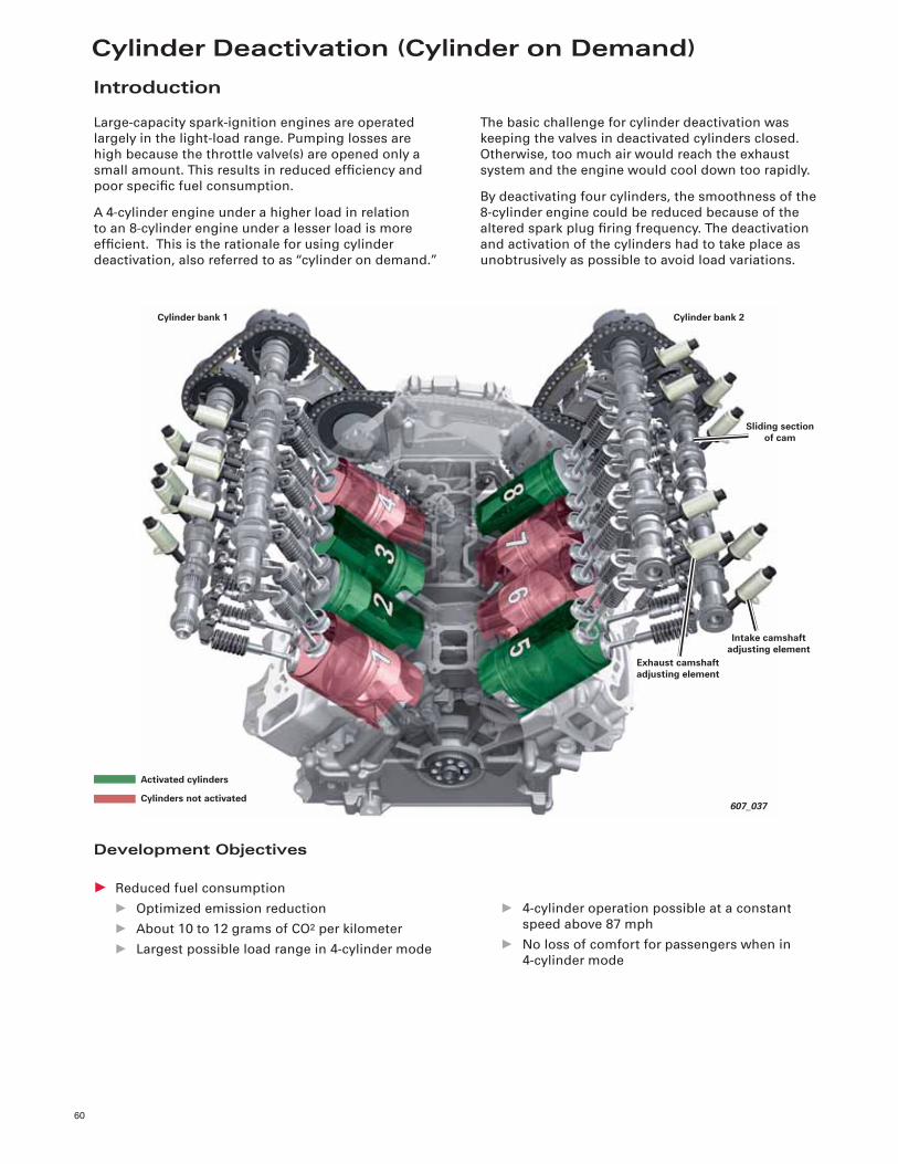
Cylinder Deactivation (Cylinder on Demand)
60
Introduction
Large-capacity spark-ignition engines are operated
largely in the light-load range. Pumping losses are
high because the throttle valve(s) are opened only a
small amount. This results in reduced effi ciency and
poor specifi c fuel consumption.
A 4-cylinder engine under a higher load in relation
to an 8-cylinder engine under a lesser load is more
effi cient. This is the rationale for using cylinder
deactivation, also referred to as “cylinder on demand.”
The basic challenge for cylinder deactivation was
keeping the valves in deactivated cylinders closed.
Otherwise, too much air would reach the exhaust
system and the engine would cool down too rapidly.
By deactivating four cylinders, the smoothness of the
8-cylinder engine could be reduced because of the
altered spark plug fi ring frequency. The deactivation
and activation of the cylinders had to take place as
unobtrusively as possible to avoid load variations.
Development Objectives
• Reduced fuel consumption
• Optimized emission reduction
• About 10 to 12 grams of CO2 per kilometer
• Largest possible load range in 4-cylinder mode
• 4-cylinder operation possible at a constant
speed above 87 mph
• No loss of comfort for passengers when in
4-cylinder mode
607_037
Intake camshaft adjusting element
Sliding section of cam
Cylinder bank 1
Exhaust camshaft adjusting element
Cylinder bank 2
Activated cylinders
Cylinders not activated
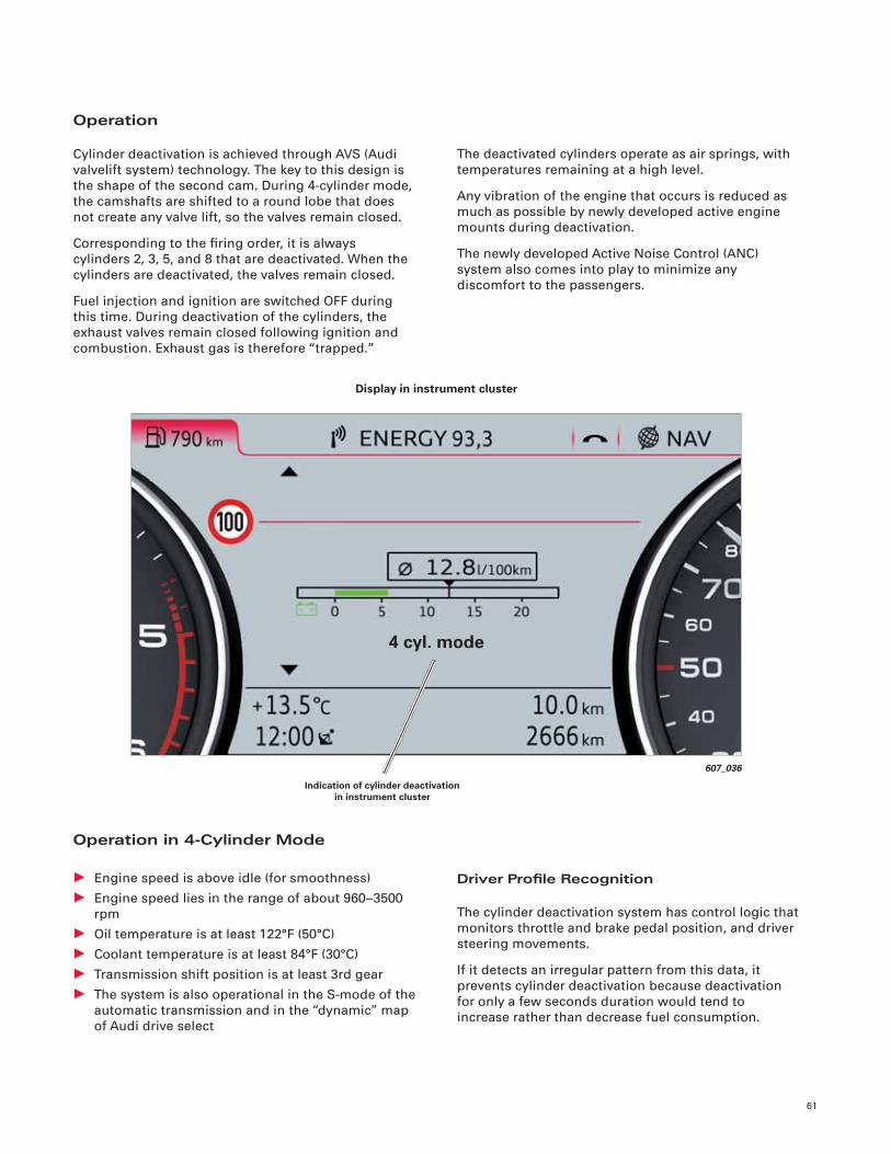
61
Operation
Cylinder deactivation is achieved through AVS (Audi
valvelift system) technology. The key to this design is
the shape of the second cam. During 4-cylinder mode,
the camshafts are shifted to a round lobe that does
not create any valve lift, so the valves remain closed.
Corresponding to the fi ring order, it is always
cylinders 2, 3, 5, and 8 that are deactivated. When the
cylinders are deactivated, the valves remain closed.
Fuel injection and ignition are switched OFF during
this time. During deactivation of the cylinders, the
exhaust valves remain closed following ignition and
combustion. Exhaust gas is therefore “trapped.”
The deactivated cylinders operate as air springs, with
temperatures remaining at a high level.
Any vibration of the engine that occurs is reduced as
much as possible by newly developed active engine
mounts during deactivation.
The newly developed Active Noise Control (ANC)
system also comes into play to minimize any
discomfort to the passengers.
Driver Profi le Recognition
The cylinder deactivation system has control logic that
monitors throttle and brake pedal position, and driver
steering movements.
If it detects an irregular pattern from this data, it
prevents cylinder deactivation because deactivation
for only a few seconds duration would tend to
increase rather than decrease fuel consumption.
Operation in 4-Cylinder Mode
• Engine speed is above idle (for smoothness)
• Engine speed lies in the range of about 960–3500
rpm
• Oil temperature is at least 122°F (50°C)
• Coolant temperature is at least 84°F (30°C)
• Transmission shift position is at least 3rd gear
• The system is also operational in the S-mode of the
automatic transmission and in the “dynamic” map
of Audi drive select
607_036
Indication of cylinder deactivation in instrument cluster
Display in instrument cluster
4 cyl. mode
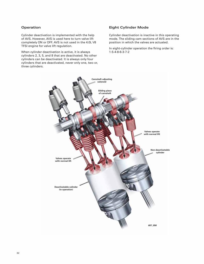
62
Operation
Cylinder deactivation is implemented with the help
of AVS. However, AVS is used here to turn valve lift
completely ON or OFF. AVS is not used in the 4.0L V8
TFSI engine for valve lift regulation.
When cylinder deactivation is active, it is always
cylinders 2, 3, 5, and 8 that are deactivated. No other
cylinders can be deactivated. It is always only four
cylinders that are deactivated, never only one, two or,
three cylinders.
Eight Cylinder Mode
Cylinder deactivation is inactive in this operating
mode. The sliding cam sections of AVS are in the
position in which the valves are actuated.
In eight-cylinder operation the fi ring order is:
1-5-4-8-6-3-7-2
607_056
Non-deactivatable cylinder
Sliding piece of camshaft
Deactivatable cylinder (in operation)
Camshaft adjusting solenoid
Valves operate with normal lift
Valves operate with normal lift
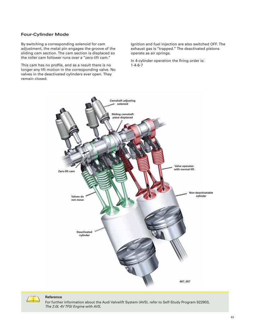
63
607_057
Non-deactivatable cylinder
Sliding camshaft piece displaced
Zero-lift cam
Camshaft adjusting solenoid
Valve operates with normal lift
Valves do not move
Deactivated cylinder
Four-Cylinder Mode
By switching a corresponding solenoid for cam
adjustment, the metal pin engages the groove of the
sliding cam section. The cam section is displaced so
the roller cam follower runs over a “zero-lift cam.”
This cam has no profi le, and as a result there is no
longer any lift motion in the corresponding valve. No
valves in the deactivated cylinders ever open. They
remain closed.
Ignition and fuel injection are also switched OFF. The
exhaust gas is “trapped.” The deactivated pistons
operate as air springs.
In 4-cylinder operation the fi ring order is:
1-4-6-7
ReferenceFor further information about the Audi Valvelift System (AVS), refer to Self-Study Program 922903,
The 2.0L 4V TFSI Engine with AVS.
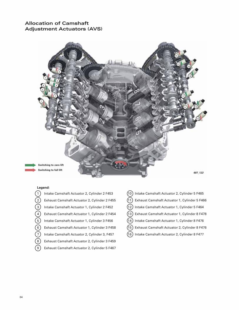
64
Allocation of Camshaft Adjustment Actuators (AVS)
Legend:
1 Intake Camshaft Actuator 2, Cylinder 2 F453
2 Exhaust Camshaft Actuator 2, Cylinder 2 F455
3 Intake Camshaft Actuator 1, Cylinder 2 F452
4 Exhaust Camshaft Actuator 1, Cylinder 2 F454
5 Intake Camshaft Actuator 1, Cylinder 3 F456
6 Exhaust Camshaft Actuator 1, Cylinder 3 F458
7 Intake Camshaft Actuator 2, Cylinder 3, F457
8 Exhaust Camshaft Actuator 2, Cylinder 3 F459
9 Exhaust Camshaft Actuator 2, Cylinder 5 F467
10 Intake Camshaft Actuator 2, Cylinder 5 F465
11 Exhaust Camshaft Actuator 1, Cylinder 5 F466
12 Intake Camshaft Actuator 1, Cylinder 5 F464
13 Exhaust Camshaft Actuator 1, Cylinder 8 F478
14 Intake Camshaft Actuator 1, Cylinder 8 F476
15 Exhaust Camshaft Actuator 2, Cylinder 8 F476
16 Intake Camshaft Actuator 2, Cylinder 8 F477
607_122
1
2
3
45
6
7
8
9
10
11
12
13
14
15
16
Switching to zero lift
Switching to full lift
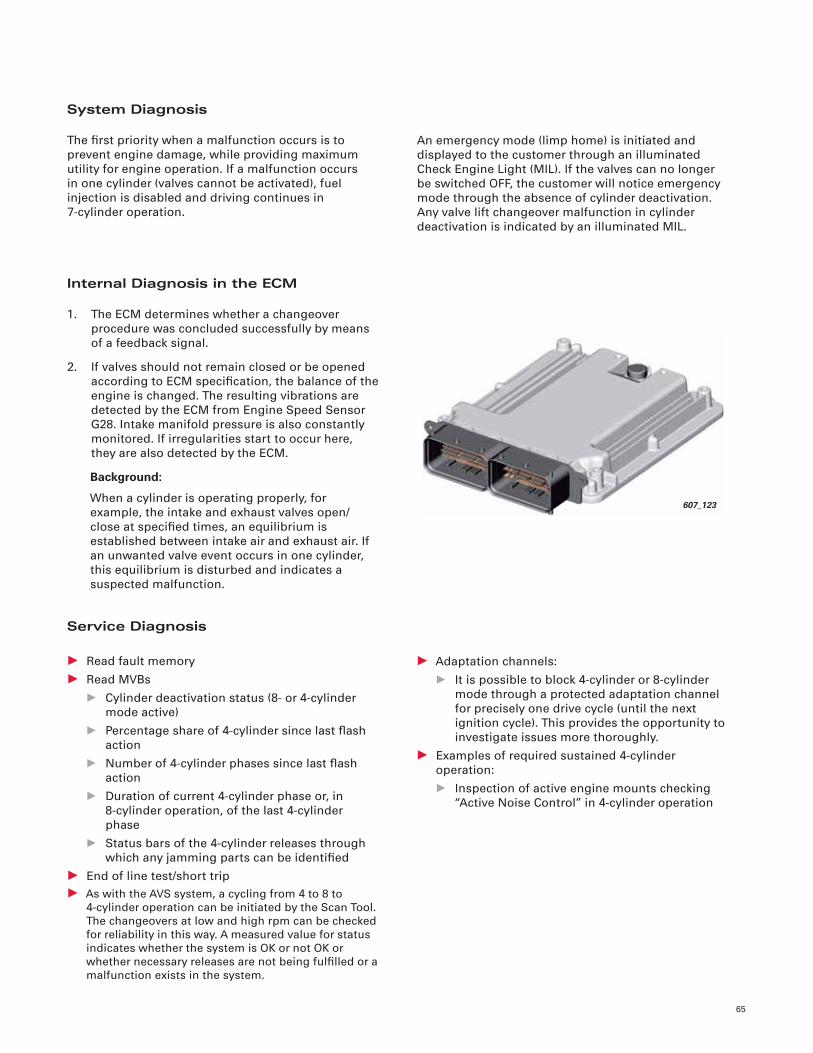
65
System Diagnosis
The fi rst priority when a malfunction occurs is to
prevent engine damage, while providing maximum
utility for engine operation. If a malfunction occurs
in one cylinder (valves cannot be activated), fuel
injection is disabled and driving continues in
7-cylinder operation.
An emergency mode (limp home) is initiated and
displayed to the customer through an illuminated
Check Engine Light (MIL). If the valves can no longer
be switched OFF, the customer will notice emergency
mode through the absence of cylinder deactivation.
Any valve lift changeover malfunction in cylinder
deactivation is indicated by an illuminated MIL.
Internal Diagnosis in the ECM
1. The ECM determines whether a changeover
procedure was concluded successfully by means
of a feedback signal.
2. If valves should not remain closed or be opened
according to ECM specifi cation, the balance of the
engine is changed. The resulting vibrations are
detected by the ECM from Engine Speed Sensor
G28. Intake manifold pressure is also constantly
monitored. If irregularities start to occur here,
they are also detected by the ECM.
Background:
When a cylinder is operating properly, for
example, the intake and exhaust valves open/
close at specifi ed times, an equilibrium is
established between intake air and exhaust air. If
an unwanted valve event occurs in one cylinder,
this equilibrium is disturbed and indicates a
suspected malfunction.
Service Diagnosis
• Read fault memory
• Read MVBs
• Cylinder deactivation status (8- or 4-cylinder
mode active)
• Percentage share of 4-cylinder since last fl ash
action
• Number of 4-cylinder phases since last fl ash
action
• Duration of current 4-cylinder phase or, in
8-cylinder operation, of the last 4-cylinder
phase
• Status bars of the 4-cylinder releases through
which any jamming parts can be identifi ed
• End of line test/short trip
• As with the AVS system, a cycling from 4 to 8 to
4-cylinder operation can be initiated by the Scan Tool.
The changeovers at low and high rpm can be checked
for reliability in this way. A measured value for status
indicates whether the system is OK or not OK or
whether necessary releases are not being fulfi lled or a
malfunction exists in the system.
• Adaptation channels:
• It is possible to block 4-cylinder or 8-cylinder
mode through a protected adaptation channel
for precisely one drive cycle (until the next
ignition cycle). This provides the opportunity to
investigate issues more thoroughly.
• Examples of required sustained 4-cylinder
operation:
• Inspection of active engine mounts checking
“Active Noise Control” in 4-cylinder operation
607_123
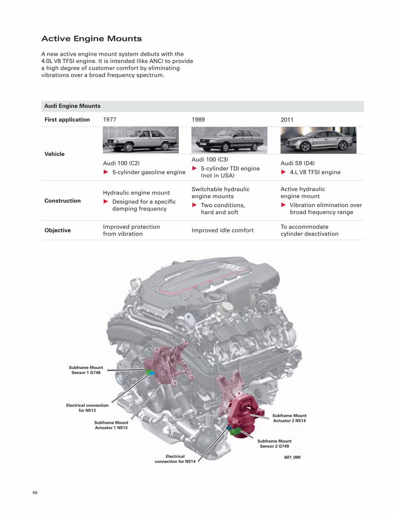
66
Active Engine Mounts
A new active engine mount system debuts with the
4.0L V8 TFSI engine. It is intended (like ANC) to provide
a high degree of customer comfort by eliminating
vibrations over a broad frequency spectrum.
Audi Engine Mounts
First application
Vehicle
Construction
1989
Audi 100 (C3)
• 5-cylinder TDI engine
(not in USA)
Switchable hydraulic
engine mounts
• Two conditions,
hard and soft
2011
Audi S9 (D4)
• 4.L V8 TFSI engine
Active hydraulic
engine mount
• Vibration elimination over
broad frequency range
Objective Improved idle comfortTo accommodate
cylinder deactivation
1977
Audi 100 (C2)
• 5-cylinder gasoline engine
Hydraulic engine mount
• Designed for a specifi c
damping frequency
Improved protection
from vibration
607_090
Subframe Mount Actuator 2 N514
Subframe Mount Sensor 2 G749
Subframe Mount Actuator 1 N513
Electrical connection for N514
Electrical connection for N513
Subframe Mount Sensor 1 G748
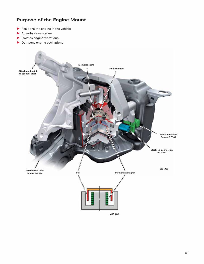
67
Purpose of the Engine Mount
• Positions the engine in the vehicle
• Absorbs drive torque
• Isolates engine vibrations
• Dampens engine oscillations
607_083
Electrical connection for N514
Attachment point to long member Coil
Membrane ring
Subframe Mount Sensor 2 G749
Permanent magnet
Fluid chamberAttachment point to cylinder block
607_124
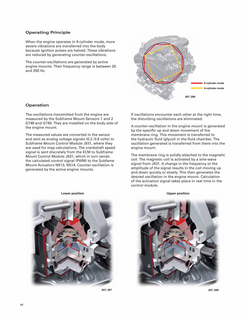
68
Operating Principle
When the engine operates in 4-cylinder mode, more
severe vibrations are transferred into the body
because ignition pulses are halved. These vibrations
are reduced by generating counter-oscillations.
The counter-oscillations are generated by active
engine mounts. Their frequency range is between 20
and 250 Hz.
Operation
The oscillations transmitted from the engine are
measured by the Subframe Mount Sensors 1 and 2
G748 and G749. They are installed on the body side of
the engine mount.
The measured values are converted in the sensor
and sent as analog voltage signals (0.2–0.8 volts) to
Subframe Mount Control Module J931, where they
are used for map calculations. The crankshaft speed
signal is sent discretely from the ECM to Subframe
Mount Control Module J931, which in turn sends
the calculated control signal (PWM) to the Subfame
Mount Actuators N513, N514. Counter-oscillation is
generated by the active engine mounts.
If oscillations encounter each other at the right time,
the disturbing oscillations are eliminated.
A counter-oscillation in the engine mount is generated
by the specifi c up and down movement of the
membrane ring. This movement is transferred to
the hydraulic fl uid (glycol) in the fl uid chamber. The
oscillation generated is transferred from there into the
engine mount.
The membrane ring is solidly attached to the magnetic
coil. The magnetic coil is activated by a sine-wave
signal from J931. A change in the frequency or the
amplitude of the signal results in the coil moving up
and down quickly or slowly. This then generates the
desired oscillation in the engine mount. Calculation
of the activation signal takes place in real time in the
control module.
607_096
8-cylinder mode
4-cylinder mode
607_098
Upper position
607_097
Lower position
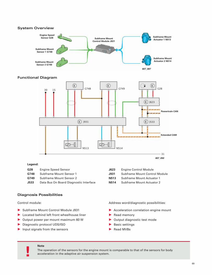
69
System Overview
Functional Diagram
Diagnosis Possibilities
Control module:
• Subframe Mount Control Module J931
• Located behind left front wheelhouse liner
• Output power per mount maximum 60 W
• Diagnostic protocol UDS/ISO
• Input signals from the sensors
Address word/diagnostic possibilities:
• Acceleration correlation engine mount
• Read memory
• Output diagnostic test mode
• Basic settings
• Read MVBs
NoteThe operation of the sensors for the engine mount is comparable to that of the sensors for body
acceleration in the adaptive air suspension system. !
607_050
Extended CAM
Powertrain CAN
Subframe Mount Sensor 1 G748
Subframe Mount Control Module J931
Engine Speed Sensor G28
Subframe Mount Sensor 2 G749
Subframe Mount Actuator 1 N513
Subframe Mount Actuator 2 N514
607_087
J623 Engine Control Module
J931 Subframe Mount Control Module
N513 Subframe Mount Actuator 1
N514 Subframe Mount Actuator 2
Legend:
G28 Engine Speed Sensor
G748 Subframe Mount Sensor 1
G749 Subframe Mount Sensor 2
J533 Data Bus On Board Diagnostic Interface
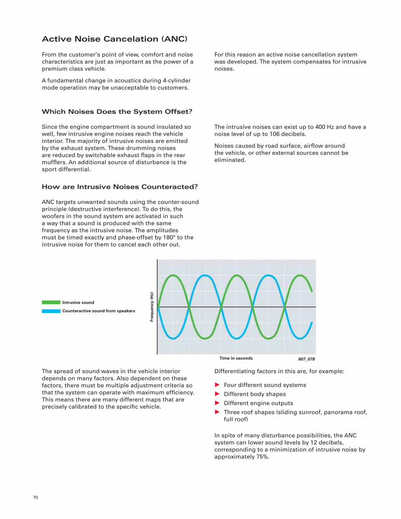
70
Active Noise Cancelation (ANC)
From the customer’s point of view, comfort and noise
characteristics are just as important as the power of a
premium class vehicle.
A fundamental change in acoustics during 4-cylinder
mode operation may be unacceptable to customers.
For this reason an active noise cancellation system
was developed. The system compensates for intrusive
noises.
Which Noises Does the System Offset?
Since the engine compartment is sound insulated so
well, few intrusive engine noises reach the vehicle
interior. The majority of intrusive noises are emitted
by the exhaust system. These drumming noises
are reduced by switchable exhaust fl aps in the rear
muffl ers. An additional source of disturbance is the
sport differential.
The intrusive noises can exist up to 400 Hz and have a
noise level of up to 106 decibels.
Noises caused by road surface, airfl ow around
the vehicle, or other external sources cannot be
eliminated.
How are Intrusive Noises Counteracted?
ANC targets unwanted sounds using the counter-sound
principle (destructive interference). To do this, the
woofers in the sound system are activated in such
a way that a sound is produced with the same
frequency as the intrusive noise. The amplitudes
must be timed exactly and phase-offset by 180° to the
intrusive noise for them to cancel each other out.
The spread of sound waves in the vehicle interior
depends on many factors. Also dependent on these
factors, there must be multiple adjustment criteria so
that the system can operate with maximum effi ciency.
This means there are many different maps that are
precisely calibrated to the specifi c vehicle.
Differentiating factors in this are, for example:
• Four different sound systems
• Different body shapes
• Different engine outputs
• Three roof shapes (sliding sunroof, panorama roof,
full roof)
In spite of many disturbance possibilities, the ANC
system can lower sound levels by 12 decibels,
corresponding to a minimization of intrusive noise by
approximately 75%.
Intrusive sound
Counteractive sound from speakers
607_078Time in seconds
Freq
uen
cy (H
z)
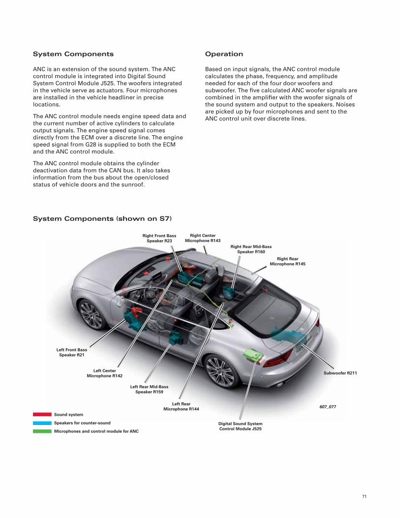
71
607_077
Left Rear Mid-Bass Speaker R159
Right Center Microphone R143
Left Rear Microphone R144
Right Front Bass Speaker R23
Right Rear Mid-Bass Speaker R160
Right Rear Microphone R145
Left Front Bass Speaker R21
Left Center Microphone R142
Digital Sound System Control Module J525
Subwoofer R211
System Components
ANC is an extension of the sound system. The ANC
control module is integrated into Digital Sound
System Control Module J525. The woofers integrated
in the vehicle serve as actuators. Four microphones
are installed in the vehicle headliner in precise
locations.
The ANC control module needs engine speed data and
the current number of active cylinders to calculate
output signals. The engine speed signal comes
directly from the ECM over a discrete line. The engine
speed signal from G28 is supplied to both the ECM
and the ANC control module.
The ANC control module obtains the cylinder
deactivation data from the CAN bus. It also takes
information from the bus about the open/closed
status of vehicle doors and the sunroof.
Operation
Based on input signals, the ANC control module
calculates the phase, frequency, and amplitude
needed for each of the four door woofers and
subwoofer. The fi ve calculated ANC woofer signals are
combined in the amplifi er with the woofer signals of
the sound system and output to the speakers. Noises
are picked up by four microphones and sent to the
ANC control unit over discrete lines.
System Components (shown on S7)
Sound system
Speakers for counter-sound
Microphones and control module for ANC
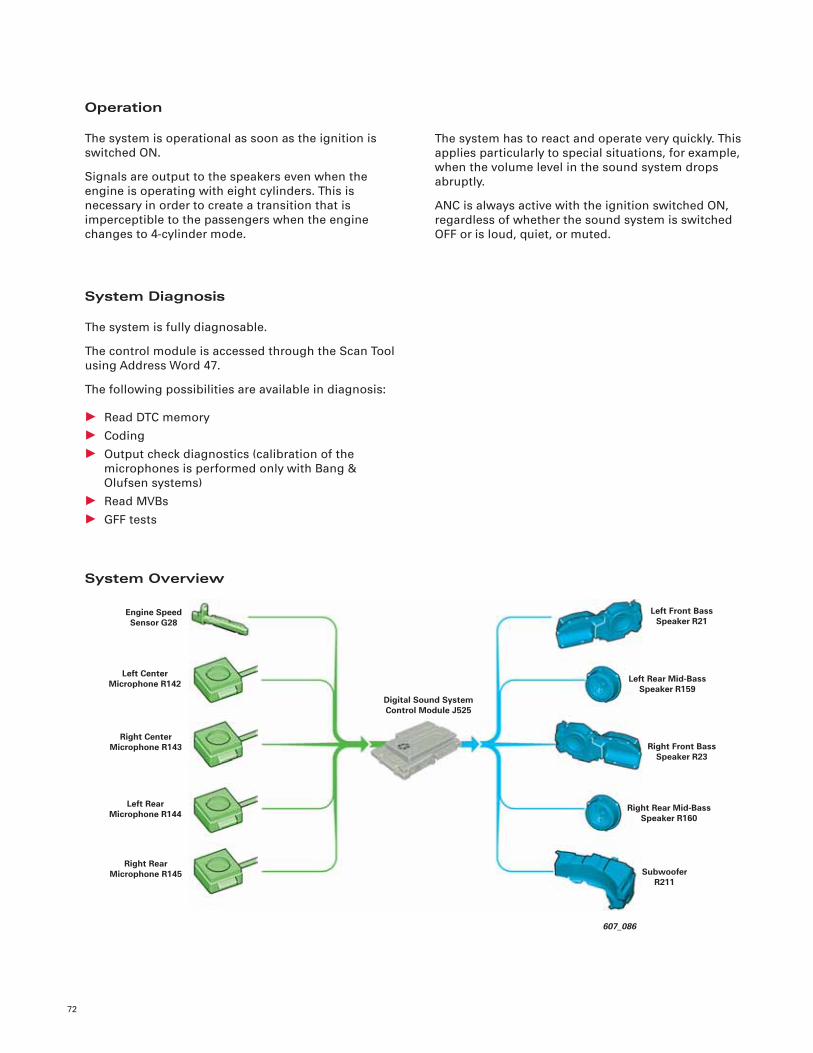
72
Operation
The system is operational as soon as the ignition is
switched ON.
Signals are output to the speakers even when the
engine is operating with eight cylinders. This is
necessary in order to create a transition that is
imperceptible to the passengers when the engine
changes to 4-cylinder mode.
System Diagnosis
The system is fully diagnosable.
The control module is accessed through the Scan Tool
using Address Word 47.
The following possibilities are available in diagnosis:
• Read DTC memory
• Coding
• Output check diagnostics (calibration of the
microphones is performed only with Bang &
Olufsen systems)
• Read MVBs
• GFF tests
The system has to react and operate very quickly. This
applies particularly to special situations, for example,
when the volume level in the sound system drops
abruptly.
ANC is always active with the ignition switched ON,
regardless of whether the sound system is switched
OFF or is loud, quiet, or muted.
System Overview
607_086
Left Rear Mid-Bass Speaker R159
Right Front Bass Speaker R23
Digital Sound System Control Module J525
Engine Speed Sensor G28
Left Front Bass Speaker R21
Left Center Microphone R142
Right Center Microphone R143
Left Rear Microphone R144
Right Rear Microphone R145
Right Rear Mid-Bass Speaker R160
Subwoofer R211
73
ANC Deactivation
ANC may be deactivated under the following
conditions:
• On Bang & Olufsen system, window open*
• On Bang & Olufsen system, sunroof open*
• Doors and rear hatch open
• Wind turbulence at one microphone
• Default operation to only three microphones
• Deactivation if multiple microphones are in use
• First 10–20 hours are for characteristics
adaptation
• ECM reports that the MIL is ON
• No switching between 4- and 8-cylinder modes
• Hall signal is implausible
• Speed signal not present
• Microphones defective
• Variability of interior
• Rear seat folded down
• Ambient temperature conditions
• Mixed installation of speakers. For example, if a
new speaker was installed. A new speaker may
have a different characteristic than the ones
remaining in the vehicle. It may also be possible
that a new speaker comes from a different
manufacturer
Service
When changes are made to the engine control module
software (fl ashing) the ANC software must also be
adapted. If modifi cations are made to the exhaust
system, there may be functional interference in the
ANC system. Only OEM replacement parts should be
used.
If a customer states that the engine in their vehicle is
suddenly louder, check the sound system for DTCs.
The ANC system may be switched OFF.
Similarly, the system can switch OFF (although all the
components are “electrically” free of defects) if a part
was installed incorrectly. An Output Check Diagnosis
can help determine the root cause of the issue.
*Does not apply to BOSE Sound Systems
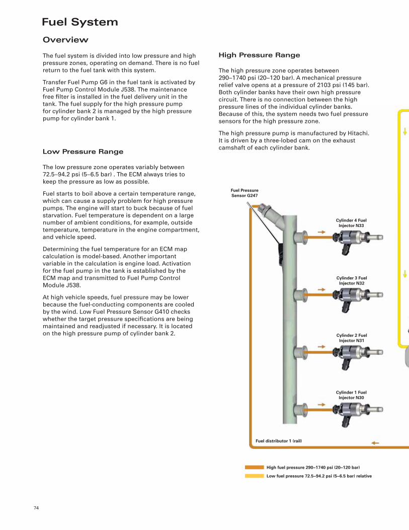
Fuel System
74
Cylinder 4 Fuel Injector N33
Fuel Pressure Sensor G247
Cylinder 3 Fuel Injector N32
Cylinder 2 Fuel Injector N31
Cylinder 1 Fuel Injector N30
Fuel distributor 1 (rail)
Overview
The fuel system is divided into low pressure and high
pressure zones, operating on demand. There is no fuel
return to the fuel tank with this system.
Transfer Fuel Pump G6 in the fuel tank is activated by
Fuel Pump Control Module J538. The maintenance
free fi lter is installed in the fuel delivery unit in the
tank. The fuel supply for the high pressure pump
for cylinder bank 2 is managed by the high pressure
pump for cylinder bank 1.
High Pressure Range
The high pressure zone operates between
290–1740 psi (20–120 bar). A mechanical pressure
relief valve opens at a pressure of 2103 psi (145 bar).
Both cylinder banks have their own high pressure
circuit. There is no connection between the high
pressure lines of the individual cylinder banks.
Because of this, the system needs two fuel pressure
sensors for the high pressure zone.
The high pressure pump is manufactured by Hitachi.
It is driven by a three-lobed cam on the exhaust
camshaft of each cylinder bank.Low Pressure Range
The low pressure zone operates variably between
72.5–94.2 psi (5–6.5 bar) . The ECM always tries to
keep the pressure as low as possible.
Fuel starts to boil above a certain temperature range,
which can cause a supply problem for high pressure
pumps. The engine will start to buck because of fuel
starvation. Fuel temperature is dependent on a large
number of ambient conditions, for example, outside
temperature, temperature in the engine compartment,
and vehicle speed.
Determining the fuel temperature for an ECM map
calculation is model-based. Another important
variable in the calculation is engine load. Activation
for the fuel pump in the tank is established by the
ECM map and transmitted to Fuel Pump Control
Module J538.
At high vehicle speeds, fuel pressure may be lower
because the fuel-conducting components are cooled
by the wind. Low Fuel Pressure Sensor G410 checks
whether the target pressure specifi cations are being
maintained and readjusted if necessary. It is located
on the high pressure pump of cylinder bank 2.
High fuel pressure 290–1740 psi (20–120 bar)
Low fuel pressure 72.5–94.2 psi (5–6.5 bar) relative
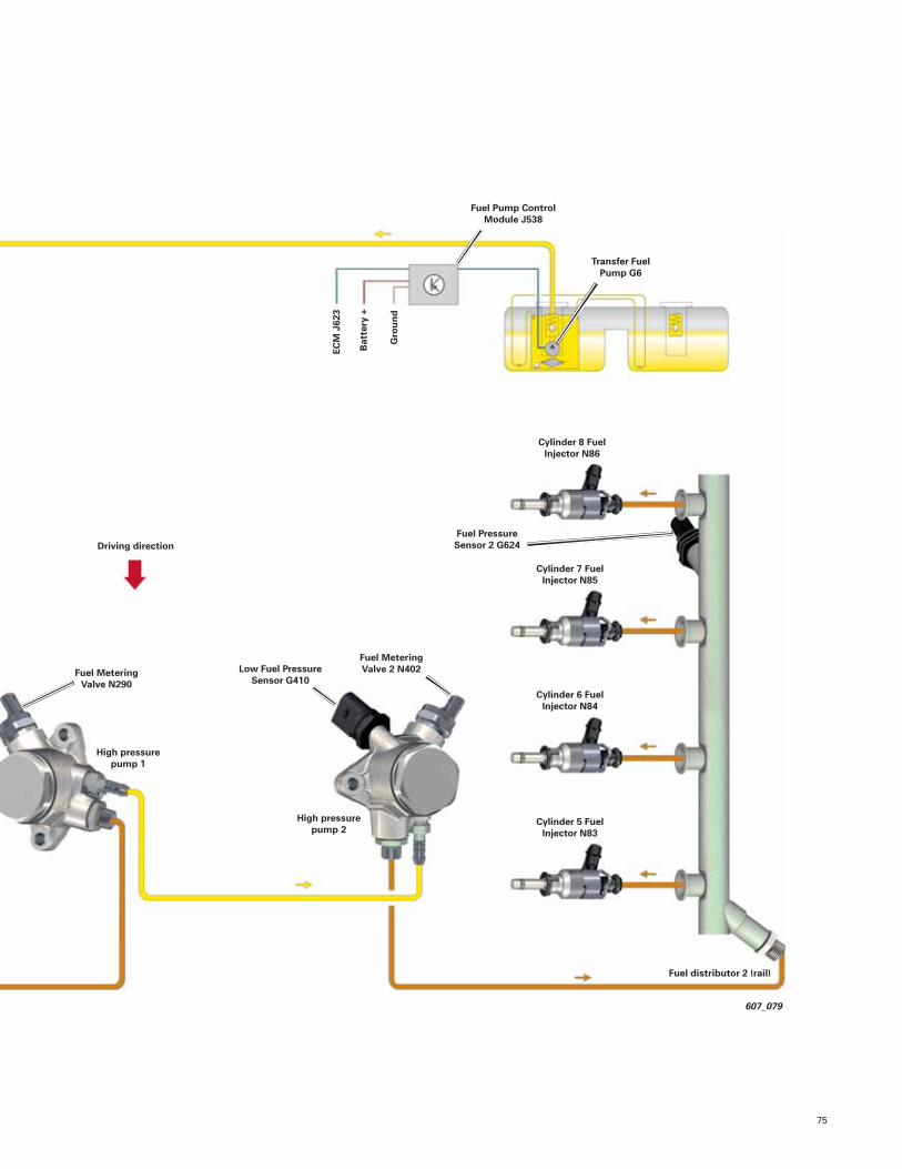
75
607_079
Low Fuel Pressure Sensor G410
High pressure pump 1
Driving direction
Fuel Pump Control Module J538
Gro
un
d
Cylinder 8 Fuel Injector N86
Transfer Fuel Pump G6
ECM
J62
3
Bat
tery
+
Cylinder 7 Fuel Injector N85
Cylinder 6 Fuel Injector N84
Cylinder 5 Fuel Injector N83
Fuel distributor 2 (rail)
High pressure pump 2
Fuel Metering Valve 2 N402
Fuel Pressure Sensor 2 G624
Fuel Metering Valve N290
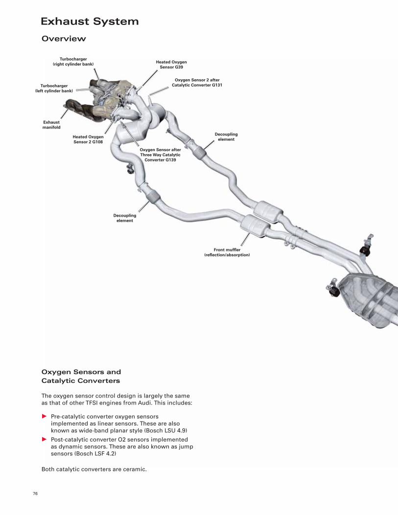
Exhaust System
76
Oxygen Sensor 2 after Catalytic Converter G131
Heated Oxygen Sensor G39
Oxygen Sensor after Three Way Catalytic
Converter G139
Turbocharger(left cylinder bank)
Exhaust manifold
Decoupling element
Decoupling elementHeated Oxygen
Sensor 2 G108
Front muffl er(refl ection/absorption)
Turbocharger(right cylinder bank)
Overview
Oxygen Sensors andCatalytic Converters
The oxygen sensor control design is largely the same
as that of other TFSI engines from Audi. This includes:
• Pre-catalytic converter oxygen sensors
implemented as linear sensors. These are also
known as wide-band planar style (Bosch LSU 4.9)
• Post-catalytic converter O2 sensors implemented
as dynamic sensors. These are also known as jump
sensors (Bosch LSF 4.2)
Both catalytic converters are ceramic.
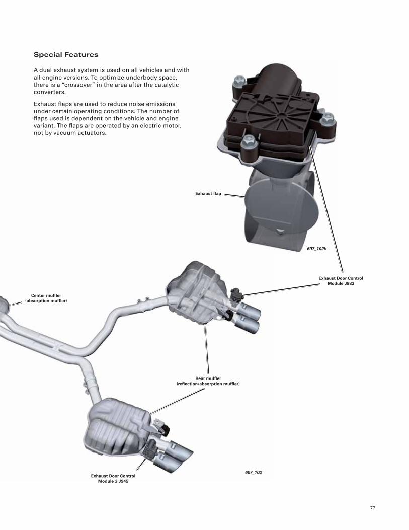
77
607_102
607_102b
Exhaust fl ap
Rear muffl er(refl ection/absorption muffl er)
Exhaust Door Control Module 2 J945
Exhaust Door Control Module J883
Center muffl er(absorption muffl er)
Special Features
A dual exhaust system is used on all vehicles and with
all engine versions. To optimize underbody space,
there is a “crossover” in the area after the catalytic
converters.
Exhaust fl aps are used to reduce noise emissions
under certain operating conditions. The number of
fl aps used is dependent on the vehicle and engine
variant. The fl aps are operated by an electric motor,
not by vacuum actuators.
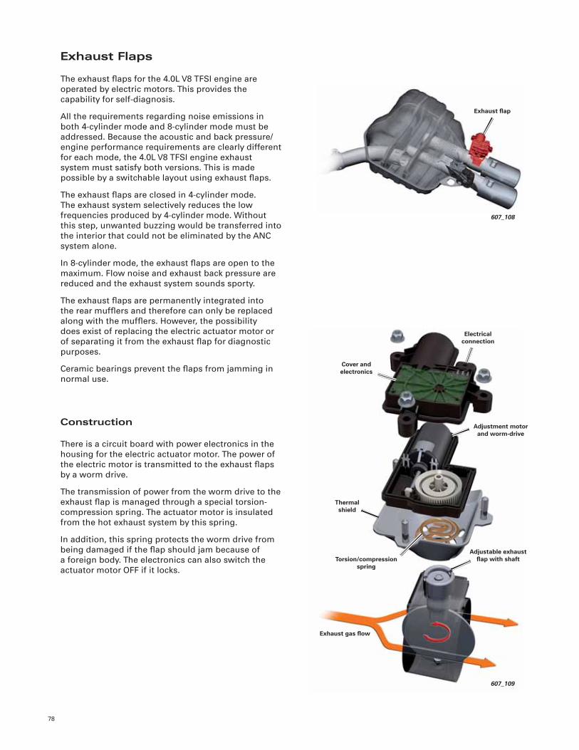
78
Exhaust Flaps
The exhaust fl aps for the 4.0L V8 TFSI engine are
operated by electric motors. This provides the
capability for self-diagnosis.
All the requirements regarding noise emissions in
both 4-cylinder mode and 8-cylinder mode must be
addressed. Because the acoustic and back pressure/
engine performance requirements are clearly different
for each mode, the 4.0L V8 TFSI engine exhaust
system must satisfy both versions. This is made
possible by a switchable layout using exhaust fl aps.
The exhaust fl aps are closed in 4-cylinder mode.
The exhaust system selectively reduces the low
frequencies produced by 4-cylinder mode. Without
this step, unwanted buzzing would be transferred into
the interior that could not be eliminated by the ANC
system alone.
In 8-cylinder mode, the exhaust fl aps are open to the
maximum. Flow noise and exhaust back pressure are
reduced and the exhaust system sounds sporty.
The exhaust fl aps are permanently integrated into
the rear muffl ers and therefore can only be replaced
along with the muffl ers. However, the possibility
does exist of replacing the electric actuator motor or
of separating it from the exhaust fl ap for diagnostic
purposes.
Ceramic bearings prevent the fl aps from jamming in
normal use.
Construction
There is a circuit board with power electronics in the
housing for the electric actuator motor. The power of
the electric motor is transmitted to the exhaust fl aps
by a worm drive.
The transmission of power from the worm drive to the
exhaust fl ap is managed through a special torsion-
compression spring. The actuator motor is insulated
from the hot exhaust system by this spring.
In addition, this spring protects the worm drive from
being damaged if the fl ap should jam because of
a foreign body. The electronics can also switch the
actuator motor OFF if it locks.
Exhaust fl ap
607_108
607_109
Adjustment motor and worm-drive
Cover and electronics
Thermal shield
Electrical connection
Torsion/compression spring
Adjustable exhaust fl ap with shaft
Exhaust gas fl ow
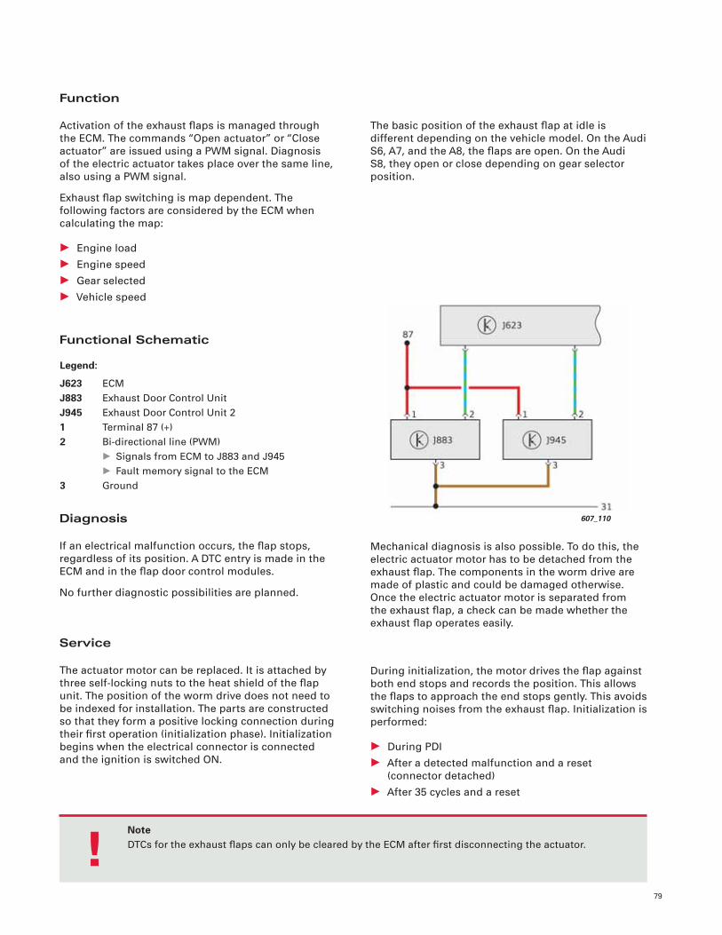
79
Function
Activation of the exhaust fl aps is managed through
the ECM. The commands “Open actuator” or “Close
actuator” are issued using a PWM signal. Diagnosis
of the electric actuator takes place over the same line,
also using a PWM signal.
Exhaust fl ap switching is map dependent. The
following factors are considered by the ECM when
calculating the map:
• Engine load
• Engine speed
• Gear selected
• Vehicle speed
Functional Schematic
The basic position of the exhaust fl ap at idle is
different depending on the vehicle model. On the Audi
S6, A7, and the A8, the fl aps are open. On the Audi
S8, they open or close depending on gear selector
position.
Diagnosis
If an electrical malfunction occurs, the fl ap stops,
regardless of its position. A DTC entry is made in the
ECM and in the fl ap door control modules.
No further diagnostic possibilities are planned.
Mechanical diagnosis is also possible. To do this, the
electric actuator motor has to be detached from the
exhaust fl ap. The components in the worm drive are
made of plastic and could be damaged otherwise.
Once the electric actuator motor is separated from
the exhaust fl ap, a check can be made whether the
exhaust fl ap operates easily.
Service
The actuator motor can be replaced. It is attached by
three self-locking nuts to the heat shield of the fl ap
unit. The position of the worm drive does not need to
be indexed for installation. The parts are constructed
so that they form a positive locking connection during
their fi rst operation (initialization phase). Initialization
begins when the electrical connector is connected
and the ignition is switched ON.
During initialization, the motor drives the fl ap against
both end stops and records the position. This allows
the fl aps to approach the end stops gently. This avoids
switching noises from the exhaust fl ap. Initialization is
performed:
• During PDI
• After a detected malfunction and a reset
(connector detached)
• After 35 cycles and a reset
NoteDTCs for the exhaust fl aps can only be cleared by the ECM after fi rst disconnecting the actuator.
!
Legend:
J623 ECM
J883 Exhaust Door Control Unit
J945 Exhaust Door Control Unit 2
1 Terminal 87 (+)
2 Bi-directional line (PWM)
• Signals from ECM to J883 and J945
• Fault memory signal to the ECM
3 Ground
607_110
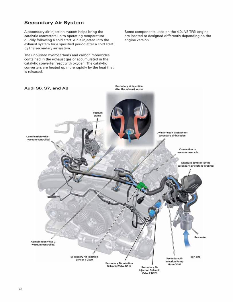
80
607_088
Separate air fi lter for the secondary air system (lifetime)
Cylinder head passage for secondary air injection
Combination valve 2 (vacuum controlled)
Secondary air injection after the exhaust valves
Connection to vacuum reservoir
Vacuum pump
Combination valve 1 (vacuum controlled)
Secondary Air Injection Sensor 1 G609
Secondary Air Injection Solenoid Valve N112 Secondary Air
Injection Solenoid Valve 2 N320
Resonator
Secondary Air Injection Pump
Motor V101
Secondary Air System
A secondary air injection system helps bring the
catalytic converters up to operating temperature
quickly following a cold start. Air is injected into the
exhaust system for a specifi ed period after a cold start
by the secondary air system.
The unburned hydrocarbons and carbon monoxides
contained in the exhaust gas or accumulated in the
catalytic converter react with oxygen. The catalytic
converters are heated up more rapidly by the heat that
is released.
Audi S6, S7, and A8
Some components used on the 4.0L V8 TFSI engine
are located or designed differently depending on the
engine version.
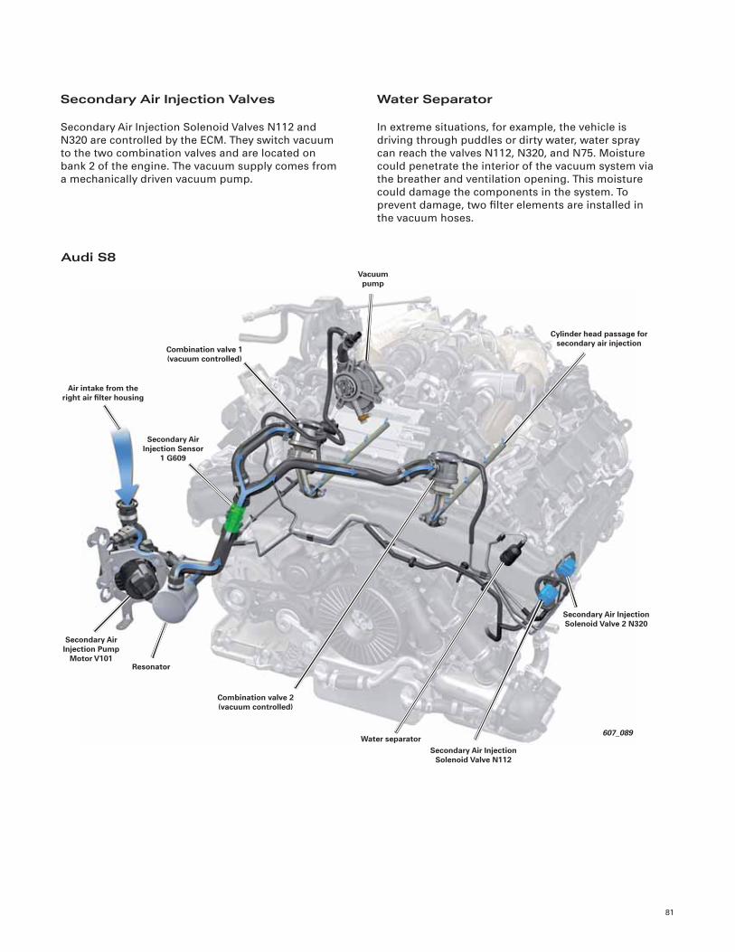
81
607_089
Combination valve 2 (vacuum controlled)
Vacuum pump
Secondary Air Injection Pump
Motor V101
Air intake from the right air fi lter housing
Cylinder head passage for secondary air injection
Secondary Air Injection Sensor
1 G609
Combination valve 1 (vacuum controlled)
Resonator
Water separator
Secondary Air Injection Solenoid Valve 2 N320
Secondary Air Injection Solenoid Valve N112
Secondary Air Injection Valves
Secondary Air Injection Solenoid Valves N112 and
N320 are controlled by the ECM. They switch vacuum
to the two combination valves and are located on
bank 2 of the engine. The vacuum supply comes from
a mechanically driven vacuum pump.
Water Separator
In extreme situations, for example, the vehicle is
driving through puddles or dirty water, water spray
can reach the valves N112, N320, and N75. Moisture
could penetrate the interior of the vacuum system via
the breather and ventilation opening. This moisture
could damage the components in the system. To
prevent damage, two fi lter elements are installed in
the vacuum hoses.
Audi S8
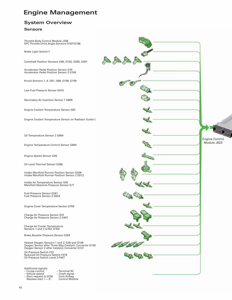
Engine Management
82
System OverviewSensors
Brake Light Switch F
Throttle Body Control Module J338EPC Throttle Drive Angle Sensors G187/G188
Camshaft Position Sensors G40, G163, G300, G301
Accelerator Pedal Position Sensor G79Accelerator Pedal Position Sensor 2 G185
Knock Sensors 1–4, G61, G66, G198, G199
Low Fuel Pressure Sensor G410
Secondary Air Injection Sensor 1 G609
Engine Coolant Temperature Sensor G62
Engine Coolant Temperature Sensor on Radiator Outlet G83
Oil Temperature Sensor 2 G664
Engine Temperature Control Sensor G694
Engine Speed Sensor G28
Oil Level Thermal Sensor G266
Intake Manifold Runner Position Sensor G336Intake Manifold Runner Position Sensor 2 G512
Intake Air Temperature Sensor G42Manifold Absolute Pressure Sensor G71
Fuel Pressure Sensor G247Fuel Pressure Sensor 2 G624
Engine Cover Temperature Sensor G765
Charge Air Pressure Sensor G31Charge Air Pressure Sensor 2 G447
Charge Air Cooler TemperatureSensors 1 and 2 G763, G764
Brake Booster Pressure Sensor G294
Heated Oxygen Sensors 1 and 2, G39 and G108Oxygen Sensor after Three-Way Catalytic Converter G130Oxygen Sensor 2 after Catalytic Converter G131
Oil Pressure Switch F22Reduced Oil Pressure Switch F378Oil Pressure Switch Level 3 F447
Additional signals:– Cruise control– Vehicle speed– Start request to ECM (Keyless start 1 + 2)
– Terminal 50– Crash signal from Airbag Control Module
Engine Control
Module J623
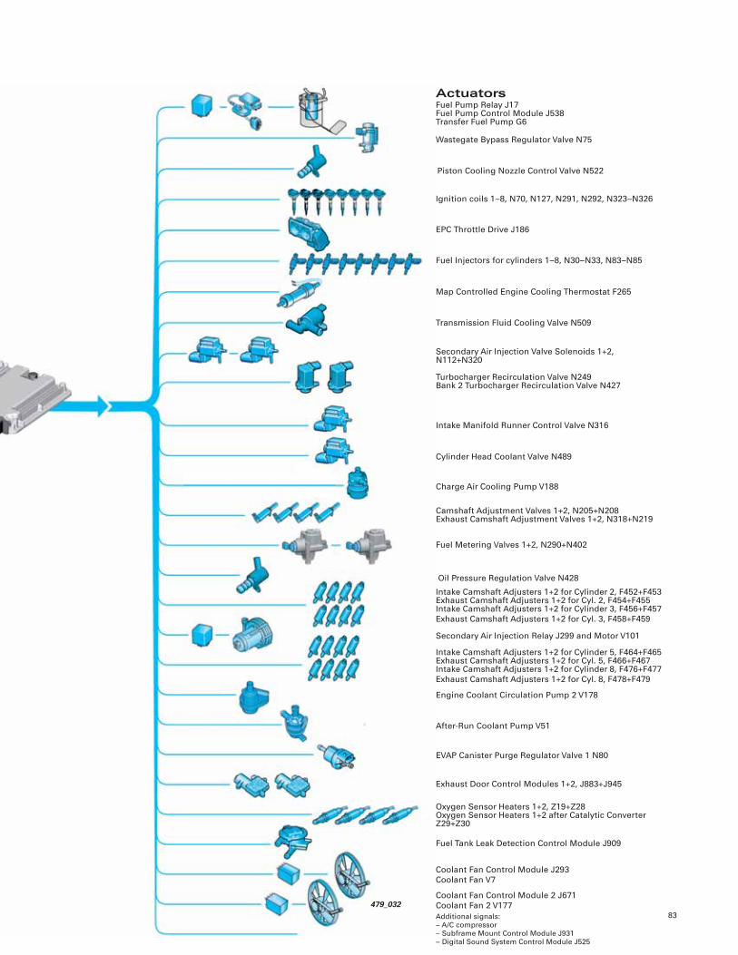
83
ActuatorsFuel Pump Relay J17Fuel Pump Control Module J538Transfer Fuel Pump G6
Wastegate Bypass Regulator Valve N75
Piston Cooling Nozzle Control Valve N522
Map Controlled Engine Cooling Thermostat F265
Transmission Fluid Cooling Valve N509
Secondary Air Injection Valve Solenoids 1+2, N112+N320
Turbocharger Recirculation Valve N249Bank 2 Turbocharger Recirculation Valve N427
Intake Manifold Runner Control Valve N316
Charge Air Cooling Pump V188
Camshaft Adjustment Valves 1+2, N205+N208Exhaust Camshaft Adjustment Valves 1+2, N318+N219
Fuel Metering Valves 1+2, N290+N402
Oil Pressure Regulation Valve N428
EVAP Canister Purge Regulator Valve 1 N80
Exhaust Door Control Modules 1+2, J883+J945
Oxygen Sensor Heaters 1+2, Z19+Z28Oxygen Sensor Heaters 1+2 after Catalytic Converter Z29+Z30
Fuel Tank Leak Detection Control Module J909
Coolant Fan Control Module J293
Coolant Fan V7
Additional signals:– A/C compressor– Subframe Mount Control Module J931– Digital Sound System Control Module J525
Ignition coils 1–8, N70, N127, N291, N292, N323–N326
EPC Throttle Drive J186
After-Run Coolant Pump V51
Engine Coolant Circulation Pump 2 V178
Secondary Air Injection Relay J299 and Motor V101
Intake Camshaft Adjusters 1+2 for Cylinder 2, F452+F453Exhaust Camshaft Adjusters 1+2 for Cyl. 2, F454+F455Intake Camshaft Adjusters 1+2 for Cylinder 3, F456+F457
Exhaust Camshaft Adjusters 1+2 for Cyl. 3, F458+F459
Cylinder Head Coolant Valve N489
Fuel Injectors for cylinders 1–8, N30–N33, N83–N85
Intake Camshaft Adjusters 1+2 for Cylinder 5, F464+F465Exhaust Camshaft Adjusters 1+2 for Cyl. 5, F466+F467Intake Camshaft Adjusters 1+2 for Cylinder 8, F476+F477
Exhaust Camshaft Adjusters 1+2 for Cyl. 8, F478+F479
Coolant Fan Control Module 2 J671
Coolant Fan 2 V177479_032
84
Engine Management MED 17.1.1
The 4.0L V8 TFSI engine uses Bosch engine
management system MED 17.1.1. Pressure and
temperature sensor signals are the principal control
variables used to register load.
Injection During Compression Stroke
A cold engine is started in “high pressure stratifi ed
start mode” using one injection event per stroke. The
injection is during the intake stroke.
There is also a sensor in the ECM to record ambient
air pressure. Its signal can be collated in the
corresponding measurement. The control module is a
UDS device and communicates over the CAN bus.
Operating Modes
As with all FSI and TFSI engines, the 4.0L V8 TFSI
engine operates in several modes. Fuel pressure and
opening times of the fuel injectors are determined by
characteristic maps.
The following descriptions refer to a cold start,
to the point when the engine reaches operating
temperature.
Warm Up
Then warm up begins. In this phase there are two
injection events until the coolant temperature has
reached 158°F (70°C).
Catalytic Converter Heating
Once the engine has started, the heating phase for
the catalytic converters begins immediately. There are
three injection events per stroke. The triple injection
lasts for a maximum of one minute (map regulated).
Catalytic converter heating is aided by secondary air
injection.
Homogeneous Operation
When coolant temperature exceeds 158°F (70°C), the
engine switches to homogenous operation. There is
one injection event on the intake stroke.
Sound Actuator System
The sound actuator system consists of the Structure
Borne Sound Control Module J869 and Structure
Borne Sound Actuator R214. Various sound fi les are
stored on J869 that are played as a function of vehicle
and operating data (load, engine speed, vehicle
speed) and forwarded to the actuator.
The actuator generates the structure-borne sound.
The sound is then introduced via the body and the
windshield to the vehicle interior. The actuator is
installed using a special bracket on the left at the base
of the windshield. The bracket is the “tuning fork” of
the system.
Different vehicles and engines require different
excitation for a balanced engine sound. Information
about the engine installed and the body are
communicated on the CAN bus and are evaluated.
J869 recognizes independently in which vehicle it
is installed. The driver can select different sound
settings through the MMI.
607_111
Structure Borne Sound Control Module J869
(under seat)
Structure-Borne Sound Actuator R214
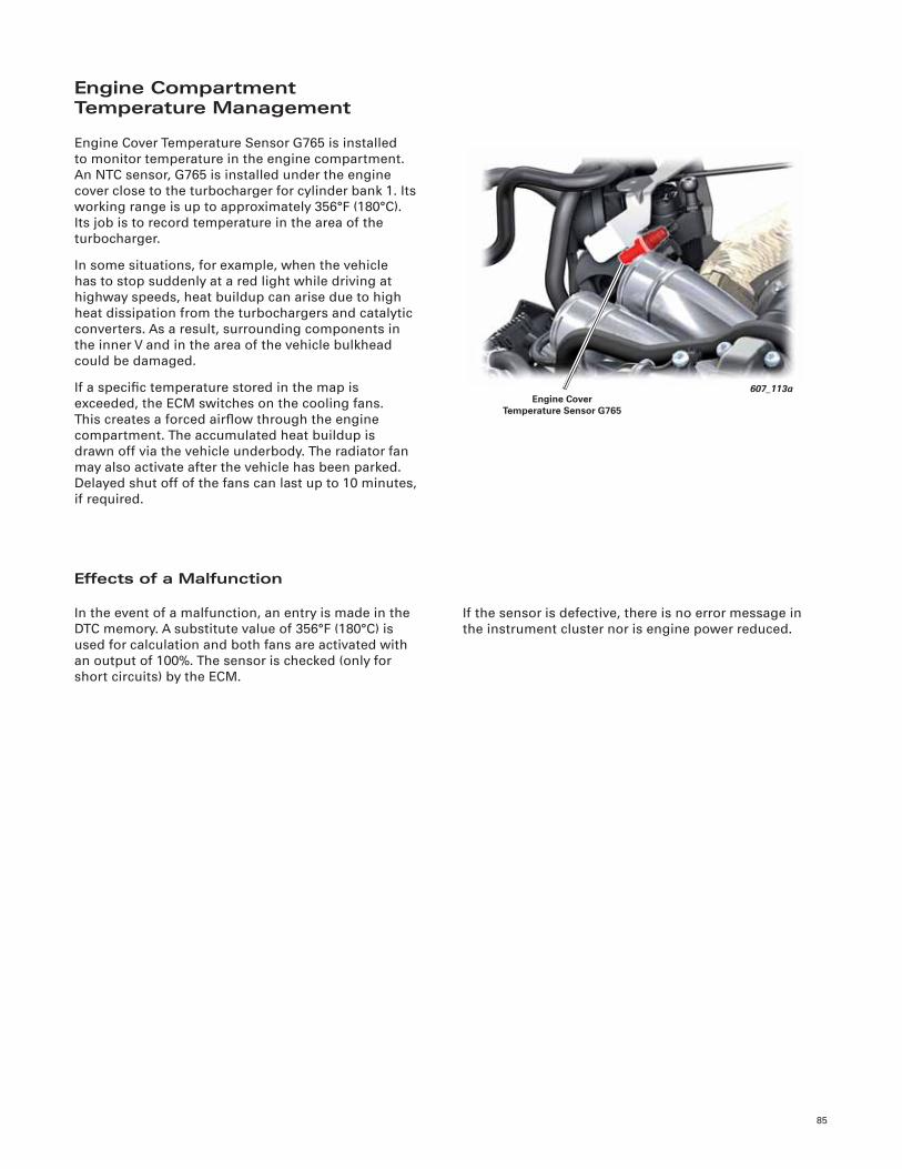
85
Engine Compartment Temperature Management
Engine Cover Temperature Sensor G765 is installed
to monitor temperature in the engine compartment.
An NTC sensor, G765 is installed under the engine
cover close to the turbocharger for cylinder bank 1. Its
working range is up to approximately 356°F (180°C).
Its job is to record temperature in the area of the
turbocharger.
In some situations, for example, when the vehicle
has to stop suddenly at a red light while driving at
highway speeds, heat buildup can arise due to high
heat dissipation from the turbochargers and catalytic
converters. As a result, surrounding components in
the inner V and in the area of the vehicle bulkhead
could be damaged.
If a specifi c temperature stored in the map is
exceeded, the ECM switches on the cooling fans.
This creates a forced airfl ow through the engine
compartment. The accumulated heat buildup is
drawn off via the vehicle underbody. The radiator fan
may also activate after the vehicle has been parked.
Delayed shut off of the fans can last up to 10 minutes,
if required.
Effects of a Malfunction
In the event of a malfunction, an entry is made in the
DTC memory. A substitute value of 356°F (180°C) is
used for calculation and both fans are activated with
an output of 100%. The sensor is checked (only for
short circuits) by the ECM.
If the sensor is defective, there is no error message in
the instrument cluster nor is engine power reduced.
607_113aEngine Cover
Temperature Sensor G765
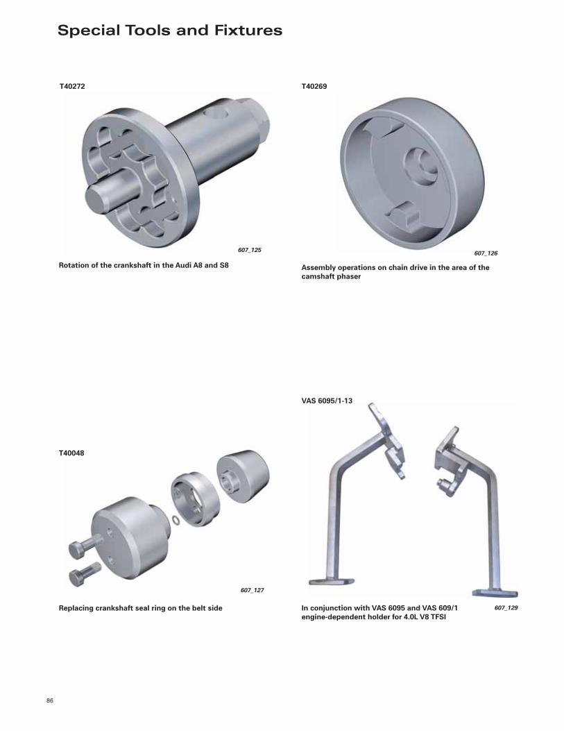
Special Tools and Fixtures
86
T40272
607_125
Rotation of the crankshaft in the Audi A8 and S8
607_126
T40269
Assembly operations on chain drive in the area of the camshaft phaser
Replacing crankshaft seal ring on the belt side
607_127
T40048
VAS 6095/1-13
607_129In conjunction with VAS 6095 and VAS 609/1engine-dependent holder for 4.0L V8 TFSI
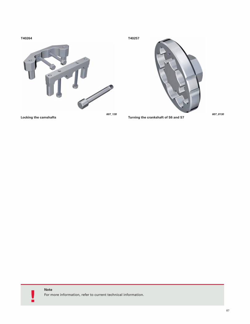
87
NoteFor more information, refer to current technical information.
!
607_0130
T40257
Turning the crankshaft of S6 and S7
T40264
607_128
Locking the camshafts

Notes
88
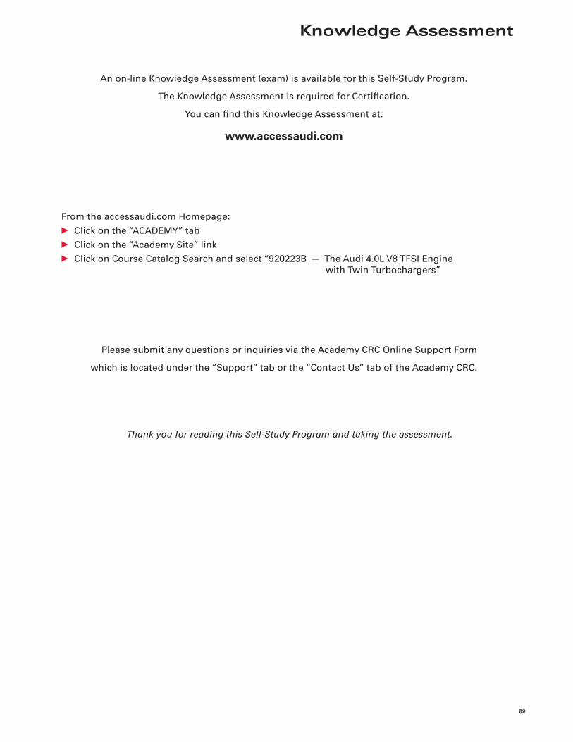
Knowledge Assessment
89
An on-line Knowledge Assessment (exam) is available for this Self-Study Program.
The Knowledge Assessment is required for Certifi cation.
You can fi nd this Knowledge Assessment at:
www.accessaudi.com
From the accessaudi.com Homepage:
• Click on the “ACADEMY” tab
• Click on the “Academy Site” link
• Click on Course Catalog Search and select “920223B — The Audi 4.0L V8 TFSI Engine
with Twin Turbochargers”
Please submit any questions or inquiries via the Academy CRC Online Support Form
which is located under the “Support” tab or the “Contact Us” tab of the Academy CRC.
Thank you for reading this Self-Study Program and taking the assessment.

Notes
90

920223
All rights reserved.Technical specifi cations subject to change without notice.
Audi of America, LLC2200 Ferdinand Porsche DriveHerndon, VA 20171